asa cluster - cisco.com ·...
TRANSCRIPT

ASA Cluster
Clustering lets you group multiple ASAs together as a single logical device. A cluster provides all theconvenience of a single device (management, integration into a network) while achieving the increasedthroughput and redundancy of multiple devices.
Some features are not supported when using clustering. See Unsupported Features with Clustering, onpage 11.
Note
• About ASA Clustering, page 1
• Licensing for ASA Clustering, page 18
• Prerequisites for ASA Clustering, page 19
• Guidelines for ASA Clustering, page 21
• Defaults for ASA Clustering, page 26
• Configure ASA Clustering, page 26
• Manage ASA Cluster Members, page 60
• Monitoring the ASA Cluster, page 64
• Examples for ASA Clustering, page 70
• History for ASA Clustering, page 90
About ASA ClusteringThis section describes the clustering architecture and how it works.
How the ASA Cluster Fits into Your NetworkThe cluster consists of multiple ASAs acting as a single unit. To act as a cluster, the ASAs need the followinginfrastructure:
CLI Book 1: Cisco ASA Series General Operations CLI Configuration Guide, 9.5 1

• Isolated, high-speed backplane network for intra-cluster communication, known as the cluster controllink.
• Management access to each ASA for configuration and monitoring.
When you place the cluster in your network, the upstream and downstream routers need to be able toload-balance the data coming to and from the cluster using one of the following methods:
• Spanned EtherChannel (Recommended)—Interfaces on multiple members of the cluster are groupedinto a single EtherChannel; the EtherChannel performs load balancing between units.
• Policy-Based Routing (Routed firewall mode only)—The upstream and downstream routers performload balancing between units using route maps and ACLs.
• Equal-Cost Multi-Path Routing (Routed firewall mode only)—The upstream and downstream routersperform load balancing between units using equal cost static or dynamic routes.
Performance Scaling FactorWhen you combine multiple units into a cluster, you can expect a performance of approximately:
• 70% of the combined throughput
• 60% of maximum connections
• 50% of connections per second
For example, for throughput, the ASA 5585-X with SSP-40 can handle approximately 10 Gbps of real worldfirewall traffic when running alone. For a cluster of 8 units, the maximum combined throughput will beapproximately 70% of 80 Gbps (8 units x 10 Gbps): 56 Gbps.
Cluster MembersCluster members work together to accomplish the sharing of the security policy and traffic flows. This sectiondescribes the nature of each member role.
Bootstrap ConfigurationOn each device, you configure a minimal bootstrap configuration including the cluster name, cluster controllink interface, and other cluster settings. The first unit on which you enable clustering typically becomes themaster unit. When you enable clustering on subsequent units, they join the cluster as slaves.
Master and Slave Unit RolesOne member of the cluster is the master unit. The master unit is determined by the priority setting in thebootstrap configuration; the priority is set between 1 and 100, where 1 is the highest priority. All other membersare slave units. Typically, when you first create a cluster, the first unit you add becomes the master unit simplybecause it is the only unit in the cluster so far.
You must perform all configuration (aside from the bootstrap configuration) on the master unit only; theconfiguration is then replicated to the slave units. In the case of physical assets, such as interfaces, the
CLI Book 1: Cisco ASA Series General Operations CLI Configuration Guide, 9.52
ASA ClusterPerformance Scaling Factor

configuration of the master unit is mirrored on all slave units. For example, if you configure GigabitEthernet0/1 as the inside interface and GigabitEthernet 0/0 as the outside interface, then these interfaces are also usedon the slave units as inside and outside interfaces.
Some features do not scale in a cluster, and the master unit handles all traffic for those features.
Master Unit ElectionMembers of the cluster communicate over the cluster control link to elect a master unit as follows:
1 When you enable clustering for a unit (or when it first starts up with clustering already enabled), it broadcastsan election request every 3 seconds.
2 Any other units with a higher priority respond to the election request; the priority is set between 1 and100, where 1 is the highest priority.
3 If after 45 seconds, a unit does not receive a response from another unit with a higher priority, then itbecomes master.
If multiple units tie for the highest priority, the cluster unit name and then the serial number is used todetermine the master.
Note
4 If a unit later joins the cluster with a higher priority, it does not automatically become the master unit; theexisting master unit always remains as the master unless it stops responding, at which point a new masterunit is elected.
You can manually force a unit to become the master. For centralized features, if you force a master unitchange, then all connections are dropped, and you have to re-establish the connections on the new masterunit.
Note
Cluster InterfacesYou can configure data interfaces as either Spanned EtherChannels or as Individual interfaces. All datainterfaces in the cluster must be one type only. See About Cluster Interfaces, on page 26 for more information.
Cluster Control LinkEach unit must dedicate at least one hardware interface as the cluster control link. See About the ClusterControl Link, on page 26 for more information.
High Availability Within the ASA ClusterASAClustering provides high availability bymonitoring unit and interface health and by replicating connectionstates between units.
CLI Book 1: Cisco ASA Series General Operations CLI Configuration Guide, 9.5 3
ASA ClusterCluster Interfaces

Unit Health MonitoringThe master unit monitors every slave unit by sending keepalive messages over the cluster control linkperiodically (the period is configurable). Each slave unit monitors the master unit using the same mechanism.If the unit health check fails, the unit is removed from the cluster.
Interface MonitoringEach unit monitors the link status of all named hardware interfaces in use, and reports status changes to themaster unit.
• Spanned EtherChannel—Uses cluster Link Aggregation Control Protocol (cLACP). Each unit monitorsthe link status and the cLACP protocol messages to determine if the port is still active in the EtherChannel.The status is reported to the master unit.
• Individual interfaces (Routed mode only)—Each unit self-monitors its interfaces and reports interfacestatus to the master unit.
When you enable health monitoring, all physical interfaces (including the main EtherChannel and redundantinterface types) are monitored by default; you can optionally disable monitoring per interface. Only namedinterfaces can be monitored. For example, the named EtherChannel must fail to be considered failed, whichmeans all member ports of an EtherChannel must fail to trigger cluster removal (depending on your minimumport bundling setting).
A unit is removed from the cluster if its monitored interfaces fail. The amount of time before the ASA removesa member from the cluster depends on the type of interface and whether the unit is an established member oris joining the cluster. For EtherChannels (spanned or not), if the interface is down on an established member,then the ASA removes the member after 9 seconds. The ASA does not monitor interfaces for the first 90seconds that a unit joins the cluster. Interface status changes during this time will not cause the ASA to beremoved from the cluster. For non-EtherChannels, the unit is removed after 500 ms, regardless of the memberstate.
Status After FailureWhen a unit in the cluster fails, the connections hosted by that unit are seamlessly transferred to other units;state information for traffic flows is shared over the control cluster link.
If the master unit fails, then another member of the cluster with the highest priority (lowest number) becomesthe master unit.
The ASA automatically tries to rejoin the cluster, depending on the failure event.
When the ASA becomes inactive and fails to automatically rejoin the cluster, all data interfaces are shutdown; only the management-only interface can send and receive traffic. Themanagement interface remainsup using the IP address the unit received from the cluster IP pool. However if you reload, and the unit isstill inactive in the cluster, the management interface is disabled. You must use the console port for anyfurther configuration.
Note
CLI Book 1: Cisco ASA Series General Operations CLI Configuration Guide, 9.54
ASA ClusterHigh Availability Within the ASA Cluster

Rejoining the ClusterAfter a cluster member is removed from the cluster, how it can rejoin the cluster depends on why it wasremoved:
• Failed cluster control link when initially joining—After you resolve the problem with the cluster controllink, you must manually rejoin the cluster by re-enabling clustering at the console port by entering clustergroup name, and then enable.
• Failed cluster control link after joining the cluster—The ASA automatically tries to rejoin every 5minutes, indefinitely. This behavior is configurable.
• Failed data interface—The ASA automatically tries to rejoin at 5 minutes, then at 10minutes, and finallyat 20 minutes. If the join is not successful after 20 minutes, then the ASA disables clustering. After youresolve the problem with the data interface, you have to manually enable clustering at the console portby entering cluster group name, and then enable. This behavior is configurable.
• Failed ASA FirePOWER module on the ASA 5585-X—The ASA automatically tries to rejoin at 5minutes.
• Failed ASA FirePOWER software module—After you resolve the problem with the module, you mustmanually enable clustering at the console port by entering cluster group name, and then enable.
• Failed unit—If the unit was removed from the cluster because of a unit health check failure, then rejoiningthe cluster depends on the source of the failure. For example, a temporary power failure means the unitwill rejoin the cluster when it starts up again as long as the cluster control link is up and clustering isstill enabled with the enable command. The ASA attempts to rejoin the cluster every 5 seconds.
• Internal error—Internal failures include: application sync timeout; inconsistent application statuses; andso on. After you resolve the problem, you must manually rejoin the cluster by re-enabling clustering atthe console port by entering cluster group name, and then enable.
See Configure the Master Unit Bootstrap Settings, on page 45.
Data Path Connection State ReplicationEvery connection has one owner and at least one backup owner in the cluster. The backup owner does nottake over the connection in the event of a failure; instead, it stores TCP/UDP state information, so that theconnection can be seamlessly transferred to a new owner in case of a failure. The backup owner is usuallyalso the director.
Some traffic requires state information above the TCP or UDP layer. See the following table for clusteringsupport or lack of support for this kind of traffic.
Table 1: Features Replicated Across the Cluster
NotesState SupportTraffic
Keeps track of the system up time.YesUp time
Transparent mode only.YesARP Table
Transparent mode only.YesMAC address table
CLI Book 1: Cisco ASA Series General Operations CLI Configuration Guide, 9.5 5
ASA ClusterHigh Availability Within the ASA Cluster

NotesState SupportTraffic
Includes AAA rules (uauth) and identity firewall.YesUser Identity
—YesIPv6 Neighbor database
—YesDynamic routing
—NoSNMP Engine ID
VPN sessions will be disconnected if the master unitfails.
NoCentralized VPN (Site-to-Site)
Configuration ReplicationAll units in the cluster share a single configuration. You can only make configuration changes on the masterunit, and changes are automatically synced to all other units in the cluster.
ASA Cluster ManagementOne of the benefits of using ASA clustering is the ease of management. This section describes how to managethe cluster.
Management NetworkWe recommend connecting all units to a single management network. This network is separate from the clustercontrol link.
Management InterfaceFor the management interface, we recommend using one of the dedicated management interfaces. You canconfigure the management interfaces as Individual interfaces (for both routed and transparent modes) or as aSpanned EtherChannel interface.
We recommend using Individual interfaces for management, even if you use Spanned EtherChannels for yourdata interfaces. Individual interfaces let you connect directly to each unit if necessary, while a SpannedEtherChannel interface only allows remote connection to the current master unit.
If you use Spanned EtherChannel interface mode, and configure the management interface as an Individualinterface, you cannot enable dynamic routing for the management interface. You must use a static route.
Note
For an Individual interface, the Main cluster IP address is a fixed address for the cluster that always belongsto the current master unit. For each interface, you also configure a range of addresses so that each unit, includingthe current master, can use a Local address from the range. The Main cluster IP address provides consistentmanagement access to an address; when a master unit changes, the Main cluster IP address moves to the new
CLI Book 1: Cisco ASA Series General Operations CLI Configuration Guide, 9.56
ASA ClusterConfiguration Replication

master unit, so management of the cluster continues seamlessly. The Local IP address is used for routing, andis also useful for troubleshooting.
For example, you can manage the cluster by connecting to the Main cluster IP address, which is alwaysattached to the current master unit. To manage an individual member, you can connect to the Local IP address.
For outbound management traffic such as TFTP or syslog, each unit, including the master unit, uses the LocalIP address to connect to the server.
For a Spanned EtherChannel interface, you can only configure one IP address, and that IP address is alwaysattached to the master unit. You cannot connect directly to a slave unit using the EtherChannel interface; werecommend configuring the management interface as an Individual interface so that you can connect to eachunit. Note that you can use a device-local EtherChannel for management.
Master Unit Management Vs. Slave Unit ManagementAll management and monitoring can take place on the master unit. From the master unit, you can checkruntime statistics, resource usage, or other monitoring information of all units. You can also issue a commandto all units in the cluster, and replicate the console messages from slave units to the master unit.
You can monitor slave units directly if desired. Although also available from the master unit, you can performfile management on slave units (including backing up the configuration and updating images). The followingfunctions are not available from the master unit:
• Monitoring per-unit cluster-specific statistics.
• Syslog monitoring per unit (except for syslogs sent to the console when console replication is enabled).
• SNMP
• NetFlow
RSA Key ReplicationWhen you create an RSA key on the master unit, the key is replicated to all slave units. If you have an SSHsession to the Main cluster IP address, you will be disconnected if the master unit fails. The new master unituses the same key for SSH connections, so that you do not need to update the cached SSH host key when youreconnect to the new master unit.
ASDM Connection Certificate IP Address MismatchBy default, a self-signed certificate is used for the ASDM connection based on the Local IP address. If youconnect to the Main cluster IP address using ASDM, then a warning message about a mismatched IP addressappears because the certificate uses the Local IP address, and not the Main cluster IP address. You can ignorethe message and establish the ASDM connection. However, to avoid this type of warning, you can enroll acertificate that contains the Main cluster IP address and all the Local IP addresses from the IP address pool.You can then use this certificate for each cluster member.
Inter-Site ClusteringFor inter-site installations, you can take advantage of ASA clustering as long as you follow the recommendedguidelines.
CLI Book 1: Cisco ASA Series General Operations CLI Configuration Guide, 9.5 7
ASA ClusterInter-Site Clustering

You can configure each cluster chassis to belong to a separate site ID.
Site IDs work with site-specific MAC addresses. Packets sourced from the cluster use a site-specific MACaddress, while packets received by the cluster use a global MAC address. This feature prevents the switchesfrom learning the same global MAC address from both sites on two different ports, which causes MACflapping; instead, they only learn the site MAC address. Site-specificMAC addresses are supported for routedmode using Spanned EtherChannels only.
Site IDs are also used to enable flow mobility using LISP inspection.
See the following sections for more information about inter-site clustering:
• Sizing the Data Center Interconnect—Prerequisites for ASA Clustering, on page 19
• Inter-Site Guidelines—Guidelines for ASA Clustering, on page 21
• Configure Cluster Flow Mobility—Configure Cluster Flow Mobility, on page 56
• Inter-Site Examples—Examples for Inter-Site Clustering, on page 85
How the ASA Cluster Manages ConnectionsConnections can be load-balanced to multiple members of the cluster. Connection roles determine howconnections are handled in both normal operation and in a high availability situation.
Connection RolesSee the following roles defined for each connection:
• Owner—Usually, the unit that initially receives the connection. The owner maintains the TCP state andprocesses packets. A connection has only one owner. If the original owner fails, then when new unitsreceive packets from the connection, the director chooses a new owner from those units.
• Backup owner—The unit that stores TCP/UDP state information received from the owner, so that theconnection can be seamlessly transferred to a new owner in case of a failure. The backup owner doesnot take over the connection in the event of a failure. If the owner becomes unavailable, then the firstunit to receive packets from the connection (based on load balancing) contacts the backup owner for therelevant state information so it can become the new owner.
As long as the director (see below) is not the same unit as the owner, then the director is also the backupowner. If the owner chooses itself as the director, then a separate backup owner is chosen.
For inter-chassis clustering on the Firepower 9300, which can include up to 3 cluster units in one chassis,if the backup owner is on the same chassis as the owner, then an additional backup owner will be chosenfrom another chassis to protect flows from a chassis failure.
• Director—The unit that handles owner lookup requests from forwarders. When the owner receives anew connection, it chooses a director based on a hash of the source/destination IP address and ports,and sends a message to the director to register the new connection. If packets arrive at any unit otherthan the owner, the unit queries the director about which unit is the owner so it can forward the packets.A connection has only one director. If a director fails, the owner chooses a new director.
As long as the director is not the same unit as the owner, then the director is also the backup owner (seeabove). If the owner chooses itself as the director, then a separate backup owner is chosen.
CLI Book 1: Cisco ASA Series General Operations CLI Configuration Guide, 9.58
ASA ClusterHow the ASA Cluster Manages Connections

• Forwarder—A unit that forwards packets to the owner. If a forwarder receives a packet for a connectionit does not own, it queries the director for the owner, and then establishes a flow to the owner for anyother packets it receives for this connection. The director can also be a forwarder. Note that if a forwarderreceives the SYN-ACK packet, it can derive the owner directly from a SYN cookie in the packet, so itdoes not need to query the director. (If you disable TCP sequence randomization, the SYN cookie is notused; a query to the director is required.) For short-lived flows such as DNS and ICMP, instead ofquerying, the forwarder immediately sends the packet to the director, which then sends them to theowner. A connection can have multiple forwarders; the most efficient throughput is achieved by a goodload-balancing method where there are no forwarders and all packets of a connection are received bythe owner.
When a connection uses Port Address Translation (PAT), then the PAT type (per-session or multi-session)influences which member of the cluster becomes the owner of a new connection:
• Per-session PAT—The owner is the unit that receives the initial packet in the connection.
By default, TCP and DNS UDP traffic use per-session PAT.
• Multi-session PAT—The owner is always the master unit. If a multi-session PAT connection is initiallyreceived by a slave unit, then the slave unit forwards the connection to the master unit.
By default, UDP (except for DNS UDP) and ICMP traffic use multi-session PAT, so these connectionsare always owned by the master unit.
You can change the per-session PAT defaults for TCP and UDP so connections for these protocols are handledper-session or multi-session depending on the configuration. For ICMP, you cannot change from the defaultmulti-session PAT. For more information about per-session PAT, see the firewall configuration guide.
New Connection OwnershipWhen a new connection is directed to a member of the cluster via load balancing, that unit owns both directionsof the connection. If any connection packets arrive at a different unit, they are forwarded to the owner unitover the cluster control link. For best performance, proper external load balancing is required for both directionsof a flow to arrive at the same unit, and for flows to be distributed evenly between units. If a reverse flowarrives at a different unit, it is redirected back to the original unit.
Sample Data FlowThe following example shows the establishment of a new connection.
CLI Book 1: Cisco ASA Series General Operations CLI Configuration Guide, 9.5 9
ASA ClusterHow the ASA Cluster Manages Connections

1 The SYN packet originates from the client and is delivered to one ASA (based on the load balancingmethod), which becomes the owner. The owner creates a flow, encodes owner information into a SYNcookie, and forwards the packet to the server.
2 The SYN-ACK packet originates from the server and is delivered to a different ASA (based on the loadbalancing method). This ASA is the forwarder.
3 Because the forwarder does not own the connection, it decodes owner information from the SYN cookie,creates a forwarding flow to the owner, and forwards the SYN-ACK to the owner.
4 The owner sends a state update to the director, and forwards the SYN-ACK to the client.
5 The director receives the state update from the owner, creates a flow to the owner, and records the TCPstate information as well as the owner. The director acts as the backup owner for the connection.
6 Any subsequent packets delivered to the forwarder will be forwarded to the owner.
7 If packets are delivered to any additional units, it will query the director for the owner and establish a flow.
8 Any state change for the flow results in a state update from the owner to the director.
Rebalancing New TCP Connections Across the ClusterIf the load balancing capabilities of the upstream or downstream routers result in unbalanced flow distribution,you can configure overloaded units to redirect new TCP flows to other units. No existing flows will be movedto other units.
ASA Features and ClusteringSome ASA features are not supported with ASA clustering, and some are only supported on the master unit.Other features might have caveats for proper usage.
CLI Book 1: Cisco ASA Series General Operations CLI Configuration Guide, 9.510
ASA ClusterASA Features and Clustering

Unsupported Features with ClusteringThese features cannot be configured with clustering enabled, and the commands will be rejected.
• Unified Communication features that rely on TLS Proxy
• Remote access VPN (SSL VPN and IPsec VPN)
• The following application inspections:
◦CTIQBE
◦H323, H225, and RAS
◦IPsec passthrough
◦MGCP
◦MMP
◦RTSP
◦SCCP (Skinny)
◦WAAS
◦WCCP
• Botnet Traffic Filter
• Auto Update Server
• DHCP client, server, and proxy. DHCP relay is supported.
• VPN load balancing
• Failover
• ASA CX module
Centralized Features for ClusteringThe following features are only supported on the master unit, and are not scaled for the cluster. For example,you have a cluster of eight units (5585-X with SSP-60). The Other VPN license allows a maximum of 10,000site-to-site IPsec tunnels for one ASA 5585-X with SSP-60. For the entire cluster of eight units, you can onlyuse 10,000 tunnels; the feature does not scale.
Traffic for centralized features is forwarded from member units to the master unit over the cluster controllink.
If you use the rebalancing feature, traffic for centralized features may be rebalanced to non-master unitsbefore the traffic is classified as a centralized feature; if this occurs, the traffic is then sent back to themaster unit.
For centralized features, if the master unit fails, all connections are dropped, and you have to re-establishthe connections on the new master unit.
Note
CLI Book 1: Cisco ASA Series General Operations CLI Configuration Guide, 9.5 11
ASA ClusterASA Features and Clustering

• Site-to-site VPN
• The following application inspections:
◦DCERPC
◦ESMTP
◦IM
◦NetBIOS
◦PPTP
◦RADIUS
◦RSH
◦SNMP
◦SQLNET
◦SUNRPC
◦TFTP
◦XDMCP
• Dynamic routing (Spanned EtherChannel mode only)
• Multicast routing (Individual interface mode only)
• Static route monitoring
• IGMPmulticast control plane protocol processing (data plane forwarding is distributed across the cluster)
• PIMmulticast control plane protocol processing (data plane forwarding is distributed across the cluster)
• Authentication and Authorization for network access. Accounting is decentralized.
• Filtering Services
Features Applied to Individual UnitsThese features are applied to each ASA unit, instead of the cluster as a whole or to the master unit.
• QoS—The QoS policy is synced across the cluster as part of configuration replication. However, thepolicy is enforced on each unit independently. For example, if you configure policing on output, thenthe conform rate and conform burst values are enforced on traffic exiting a particular ASA. In a clusterwith 3 units and with traffic evenly distributed, the conform rate actually becomes 3 times the rate forthe cluster.
• Threat detection—Threat detection works on each unit independently; for example, the top statistics isunit-specific. Port scanning detection, for example, does not work because scanning traffic will beload-balanced between all units, and one unit will not see all traffic.
• Resourcemanagement—Resourcemanagement in multiple context mode is enforced separately on eachunit based on local usage.
CLI Book 1: Cisco ASA Series General Operations CLI Configuration Guide, 9.512
ASA ClusterASA Features and Clustering

• LISP traffic—LISP traffic on UDP port 4342 is inspected by each receiving unit, but is not assigned adirector. Each unit adds to the EID table that is shared across the cluster, but the LISP traffic itself doesnot participate in cluster state sharing.
• ASA Firepower module—There is no configuration sync or state sharing between ASA Firepowermodules. You are responsible for maintaining consistent policies on the ASA Firepower modules in thecluster using FirepowerManagement Center. Do not use different ASA-interface-based zone definitionsfor devices in the cluster.
• ASA IPS module—There is no configuration sync or state sharing between IPS modules. Some IPSsignatures require IPS to keep the state across multiple connections. For example, the port scanningsignature is used when the IPS module detects that someone is opening many connections to one serverbut with different ports. In clustering, those connections will be balanced between multiple ASA devices,each of which has its own IPS module. Because these IPS modules do not share state information, thecluster may not be able to detect port scanning as a result.
AAA for Network Access and ClusteringAAA for network access consists of three components: authentication, authorization, and accounting.Authentication and authorization are implemented as centralized features on the clustering master withreplication of the data structures to the cluster slaves. If a master is elected, the new master will have all theinformation it needs to continue uninterrupted operation of the established authenticated users and theirassociated authorizations. Idle and absolute timeouts for user authentications are preserved when a masterunit change occurs.
Accounting is implemented as a distributed feature in a cluster. Accounting is done on a per-flow basis, sothe cluster unit owning a flowwill send accounting start and stop messages to the AAA server when accountingis configured for a flow.
FTP and Clustering• If FTP data channel and control channel flows are owned by different cluster members, then the datachannel owner will periodically send idle timeout updates to the control channel owner and update theidle timeout value. However, if the control flow owner is reloaded, and the control flow is re-hosted,the parent/child flow relationship will not longer be maintained; the control flow idle timeout will notbe updated.
• If you use AAA for FTP access, then the control channel flow is centralized on the master unit.
Identity Firewall and ClusteringOnly the master unit retrieves the user-group from the AD and the user-ip mapping from the AD agent. Themaster unit then populates the user information to slaves, and slaves can make a match decision for useridentity based on the security policy.
Multicast Routing and ClusteringMulticast routing behaves differently depending on the interface mode.
CLI Book 1: Cisco ASA Series General Operations CLI Configuration Guide, 9.5 13
ASA ClusterASA Features and Clustering

Multicast Routing in Spanned EtherChannel Mode
In Spanned EtherChannel mode, the master unit handles all multicast routing packets and data packets untilfast-path forwarding is established. After the connection is established, each slave can forward multicast datapackets.
Multicast Routing in Individual Interface Mode
In Individual interface mode, units do not act independently with multicast. All data and routing packets areprocessed and forwarded by the master unit, thus avoiding packet replication.
NAT and ClusteringNAT can affect the overall throughput of the cluster. Inbound and outbound NAT packets can be sent todifferent ASAs in the cluster because the load balancing algorithm relies on IP addresses and ports, and NATcauses inbound and outbound packets to have different IP addresses and/or ports. When a packet arrives atthe ASA that is not the connection owner, it is forwarded over the cluster control link to the owner, causinglarge amounts of traffic on the cluster control link.
If you still want to use NAT in clustering, then consider the following guidelines:
• No Proxy ARP—For Individual interfaces, a proxy ARP reply is never sent for mapped addresses. Thisprevents the adjacent router from maintaining a peer relationship with an ASA that may no longer be inthe cluster. The upstream router needs a static route or PBR with Object Tracking for the mappedaddresses that points to the Main cluster IP address. This is not an issue for a Spanned EtherChannel,because there is only one IP address associated with the cluster interface.
• No interface PAT on an Individual interface—Interface PAT is not supported for Individual interfaces.
• No PAT with Port Block Allocation—This feature is not supported for the cluster.
• PAT with Port Block Allocation—See the following guidelines for this feature:
◦Maximum-per-host limit is not a cluster-wide limit, and is enforced on each unit individually.Thus, in a 3-node cluster with the maximum-per-host limit configured as 1, if the traffic from ahost is load-balanced across all 3 units, then it can get allocated 3 blocks with 1 in each unit.
◦Port blocks created on the backup unit from the backup pools are not accounted for when enforcingthe maximum-per-host limit.
◦When a PAT IP address owner goes down, the backup unit will own the PAT IP address,corresponding port blocks, and xlates. But it will not use these blocks to service new requests. Asthe connections eventually time out, the blocks get freed.
◦On-the-fly PAT rule modifications, where the PAT pool is modified with a completely new rangeof IP addresses, will result in xlate backup creation failures for the xlate backup requests that werestill in transit while the new pool became effective. This behavior is not specific to the port blockallocation feature, and is a transient PAT pool issue seen only in cluster deployments where thepool is distributed and traffic is load-balanced across the cluster units.
• NAT pool address distribution for dynamic PAT—The master unit evenly pre-distributes addressesacross the cluster. If a member receives a connection and they have no addresses left, then the connectionis dropped even if other members still have addresses available. Make sure to include at least as many
CLI Book 1: Cisco ASA Series General Operations CLI Configuration Guide, 9.514
ASA ClusterASA Features and Clustering

NAT addresses as there are units in the cluster to ensure that each unit receives an address. Use the shownat pool cluster command to see the address allocations.
• No round-robin—Round-robin for a PAT pool is not supported with clustering.
• Dynamic NAT xlates managed by the master unit—The master unit maintains and replicates the xlatetable to slave units. When a slave unit receives a connection that requires dynamic NAT, and the xlateis not in the table, it requests the xlate from the master unit. The slave unit owns the connection.
• Per-session PAT feature—Although not exclusive to clustering, the per-session PAT feature improvesthe scalability of PAT and, for clustering, allows each slave unit to own PAT connections; by contrast,multi-session PAT connections have to be forwarded to and owned by the master unit. By default, allTCP traffic and UDP DNS traffic use a per-session PAT xlate, whereas ICMP and all other UDP trafficuses multi-session. You can configure per-session NAT rules to change these defaults for TCP and UDP,but you cannot configure per-session PAT for ICMP. For traffic that benefits from multi-session PAT,such as H.323, SIP, or Skinny, you can disable per-session PAT for the associated TCP ports (the UDPports for those H.323 and SIP are already multi-session by default). For more information aboutper-session PAT, see the firewall configuration guide.
• No static PAT for the following inspections—
◦FTP
◦PPTP
◦RSH
◦SQLNET
◦TFTP
◦XDMCP
◦SIP
Dynamic Routing and ClusteringThis section describes how to use dynamic routing with clustering.
CLI Book 1: Cisco ASA Series General Operations CLI Configuration Guide, 9.5 15
ASA ClusterASA Features and Clustering

Dynamic Routing in Spanned EtherChannel Mode
In Spanned EtherChannel mode: The routing process only runs on the master unit, and routes are learnedthrough the master unit and replicated to slaves. If a routing packet arrives at a slave, it is redirected to themaster unit.
Figure 1: Dynamic Routing in Spanned EtherChannel Mode
After the slave members learn the routes from the master unit, each unit makes forwarding decisionsindependently.
The OSPF LSA database is not synchronized from the master unit to slave units. If there is a master unitswitchover, the neighboring router will detect a restart; the switchover is not transparent. The OSPF processpicks an IP address as its router ID. Although not required, you can assign a static router ID to ensure aconsistent router ID is used across the cluster. See the OSPF Non-Stop Forwarding feature to address theinterruption.
CLI Book 1: Cisco ASA Series General Operations CLI Configuration Guide, 9.516
ASA ClusterASA Features and Clustering

Dynamic Routing in Individual Interface Mode
In Individual interface mode, each unit runs the routing protocol as a standalone router, and routes are learnedby each unit independently.
Figure 2: Dynamic Routing in Individual Interface Mode
In the above diagram, Router A learns that there are 4 equal-cost paths to Router B, each through an ASA.ECMP is used to load balance traffic between the 4 paths. Each ASA picks a different router ID when talkingto external routers.
You must configure a cluster pool for the router ID so that each unit has a separate router ID.
EIGRP does not form neighbor relationships with cluster peers in individual interface mode.
If the cluster has multiple adjacencies to the same router for redundancy purposes, asymmetric routingcan lead to unacceptable traffic loss. To avoid asymmetric routing, group all of these ASA interfaces intothe same traffic zone. See Configure a Traffic Zone.
Note
SCTP and ClusteringAn SCTP association can be created on any unit (due to load balancing); its multi-homing connections mustreside on the same unit.
SIP Inspection and ClusteringA control flow can be created on any unit (due to load balancing); its child data flows must reside on the sameunit.
TLS Proxy configuration is not supported.
CLI Book 1: Cisco ASA Series General Operations CLI Configuration Guide, 9.5 17
ASA ClusterASA Features and Clustering

SNMP and ClusteringAn SNMP agent polls each individual ASA by its Local IP address. You cannot poll consolidated data forthe cluster.
You should always use the Local address, and not the Main cluster IP address for SNMP polling. If the SNMPagent polls the Main cluster IP address, if a new master is elected, the poll to the new master unit will fail.
Syslog and NetFlow and Clustering• Syslog—Each unit in the cluster generates its own syslog messages. You can configure logging so thateach unit uses either the same or a different device ID in the syslog message header field. For example,the hostname configuration is replicated and shared by all units in the cluster. If you configure loggingto use the hostname as the device ID, syslog messages generated by all units look as if they come froma single unit. If you configure logging to use the local-unit name that is assigned in the cluster bootstrapconfiguration as the device ID, syslog messages look as if they come from different units.
• NetFlow—Each unit in the cluster generates its own NetFlow stream. The NetFlow collector can onlytreat each ASA as a separate NetFlow exporter.
Cisco TrustSec and ClusteringOnly the master unit learns security group tag (SGT) information. The master unit then populates the SGT toslaves, and slaves can make a match decision for SGT based on the security policy.
VPN and ClusteringSite-to-site VPN is a centralized feature; only the master unit supports VPN connections.
Remote access VPN is not supported with clustering.Note
VPN functionality is limited to the master unit and does not take advantage of the cluster high availabilitycapabilities. If the master unit fails, all existing VPN connections are lost, and VPN users will see a disruptionin service. When a new master is elected, you must reestablish the VPN connections.
When you connect a VPN tunnel to a Spanned EtherChannel address, connections are automatically forwardedto the master unit. For connections to an Individual interface when using PBR or ECMP, you must alwaysconnect to the Main cluster IP address, not a Local address.
VPN-related keys and certificates are replicated to all units.
Licensing for ASA ClusteringCluster units do not require the same license on each unit. Typically, you buy a license only for the masterunit; slave units inherit the master license. If you have licenses on multiple units, they combine into a singlerunning ASA cluster license.
There are exceptions to this rule. See the following table for precise licensing requirements for clustering.
CLI Book 1: Cisco ASA Series General Operations CLI Configuration Guide, 9.518
ASA ClusterLicensing for ASA Clustering

License RequirementModel
Cluster License, supports up to 16 units.
Each unit must have the same encryption license; each unit must have the same 10 GE I/O/SecurityPlus license (ASA 5585-X with SSP-10 and -20).
Note
ASA 5585-X
Base license, supports 2 units.
Each unit must have the same encryptionlicense.
Note
ASA 5516-X
Security Plus license, supports 2 units.
Each unit must have the same encryptionlicense.
Note
ASA 5512-X
Base License, supports 2 units.
Each unit must have the same encryptionlicense.
Note
ASA 5515-X,ASA 5525-X,ASA 5545-X,ASA 5555-X
See ASA Cluster Licenses for the ASA on the Firepower 9300 Chassis.ASA on the Firepower9300 Chassis
No support.All other models
Prerequisites for ASA ClusteringASA Hardware and Software Requirements
All units in a cluster:
• Must be the same model with the same DRAM. You do not have to have the same amount of flashmemory.
• Must run the identical software except at the time of an image upgrade. Hitless upgrade is supported.
• Must be in the same security context mode, single or multiple.
• (Single context mode) Must be in the same firewall mode, routed or transparent.
• New cluster members must use the same SSL encryption setting (the ssl encryption command) as themaster unit for initial cluster control link communication before configuration replication.
• Must have the same cluster, encryption and, for the ASA 5585-X, 10 GE I/O licenses.
Switch Prerequisites
• Be sure to complete the switch configuration before you configure clustering on the ASAs.
• For a list of supported switches, see Cisco ASA Compatibility.
CLI Book 1: Cisco ASA Series General Operations CLI Configuration Guide, 9.5 19
ASA ClusterPrerequisites for ASA Clustering

ASA Prerequisites
• Provide each unit with a unique IP address before you join them to the management network.
◦See the Getting Started chapter for more information about connecting to the ASA and setting themanagement IP address.
◦Except for the IP address used by the master unit (typically the first unit you add to the cluster),these management IP addresses are for temporary use only.
◦After a slave joins the cluster, its management interface configuration is replaced by the onereplicated from the master unit.
• To use jumbo frames on the cluster control link (recommended), you must enable Jumbo FrameReservation before you enable clustering.
Sizing the Data Center Interconnect for Inter-Site Clustering
You should reserve bandwidth on the data center interconnect (DCI) for cluster control link traffic equivalentto the following calculation:
If the number of members differs at each site, use the larger number for your calculation. The minimumbandwidth for the DCI should not be less than the size of the cluster control link for one member.
For example:
• For 4 members at 2 sites:
◦4 cluster members total
◦2 members at each site
◦5 Gbps cluster control link per member
Reserved DCI bandwidth = 5 Gbps (2/2 x 5 Gbps).
• For 6 members at 3 sites, the size increases:
◦6 cluster members total
◦3 members at site 1, 2 members at site 2, and 1 member at site 3
◦10 Gbps cluster control link per member
Reserved DCI bandwidth = 15 Gbps (3/2 x 10 Gbps).
• For 2 members at 2 sites:
◦2 cluster members total
◦1 member at each site
◦10 Gbps cluster control link per member
CLI Book 1: Cisco ASA Series General Operations CLI Configuration Guide, 9.520
ASA ClusterPrerequisites for ASA Clustering

Reserved DCI bandwidth = 10 Gbps (1/2 x 10 Gbps = 5 Gbps; but the minimum bandwidth should notbe less than the size of the cluster control link (10 Gbps)).
Other Prerequisites
We recommend using a terminal server to access all cluster member unit console ports. For initial setup, andongoingmanagement (for example, when a unit goes down), a terminal server is useful for remotemanagement.
Guidelines for ASA ClusteringContext Mode
The mode must match on each member unit.
Firewall Mode
For single mode, the firewall mode must match on all units.
Failover
Failover is not supported with clustering.
IPv6
The cluster control link is only supported using IPv4.
Models
Supported on:
• ASA 5585-X—For the ASA 5585-X with SSP-10 and SSP-20, which include two Ten Gigabit Ethernetinterfaces, we recommend using one interface for the cluster control link, and the other for data (youcan use subinterfaces for data). Although this setup does not accommodate redundancy for the clustercontrol link, it does satisfy the need to size the cluster control link to match the size of the data interfaces.
• ASA 5516-X
• ASA 5512-X, ASA 5515-X, ASA 5525-X, ASA 5545-X, and ASA 5555-X
Switches
• For the ASR 9006, if you want to set a non-default MTU, set the ASR interface MTU to be 14 byteshigher than the cluster device MTU. Otherwise, OSPF adjacency peering attempts may fail unless themtu-ignore option is used. Note that the cluster device MTU should match the ASR IPv4MTU.
• On the switch(es) for the cluster control link interfaces, you can optionally enable Spanning Tree PortFaston the switch ports connected to the cluster unit to speed up the join process for new units.
•When you see slow bundling of a Spanned EtherChannel on the switch, you can enable LACP rate fastfor an individual interface on the switch. Note that some switches, such as the Nexus series, do notsupport LACP rate fast when performing in-service software upgrades (ISSUs), so we do not recommendusing ISSUs with clustering.
CLI Book 1: Cisco ASA Series General Operations CLI Configuration Guide, 9.5 21
ASA ClusterGuidelines for ASA Clustering

• On the switch, we recommend that you use one of the following EtherChannel load-balancing algorithms:source-dest-ip or source-dest-ip-port (see the Cisco Nexus OS and Cisco IOS port-channelload-balance command). Do not use a vlan keyword in the load-balance algorithm because it can causeunevenly distributed traffic to the devices in a cluster.Do not change the load-balancing algorithm fromthe default on the cluster device.
• If you change the load-balancing algorithm of the EtherChannel on the switch, the EtherChannel interfaceon the switch temporarily stops forwarding traffic, and the Spanning Tree Protocol restarts. There willbe a delay before traffic starts flowing again.
• Some switches do not support dynamic port priority with LACP (active and standby links). You candisable dynamic port priority to provide better compatibility with spanned EtherChannels.
• Switches on the cluster control link path should not verify the L4 checksum. Redirected traffic over thecluster control link does not have a correct L4 checksum. Switches that verify the L4 checksum couldcause traffic to be dropped.
• Port-channel bundling downtime should not exceed the configured keepalive interval.
• On Supervisor 2T EtherChannels, the default hash distribution algorithm is adaptive. To avoid asymmetrictraffic in a VSS design, change the hash algorithm on the port-channel connected to the cluster deviceto fixed:
router(config)# port-channel id hash-distribution fixed
Do not change the algorithm globally; you may want to take advantage of the adaptive algorithm for theVSS peer link.
• You should disable the LACPGraceful Convergence feature on all cluster-facing EtherChannel interfacesfor Cisco Nexus switches.
EtherChannels
• In Catalyst 3750-X Cisco IOS software versions earlier than 15.1(1)S2, the cluster unit did not supportconnecting an EtherChannel to a switch stack.With default switch settings, if the cluster unit EtherChannelis connected cross stack, and if the master switch is powered down, then the EtherChannel connectedto the remaining switch will not come up. To improve compatibility, set the stack-mac persistent timercommand to a large enough value to account for reload time; for example, 8 minutes or 0 for indefinite.Or, you can upgrade to more a more stable switch software version, such as 15.1(1)S2.
• Spanned vs. Device-Local EtherChannel Configuration—Be sure to configure the switch appropriatelyfor Spanned EtherChannels vs. Device-local EtherChannels.
◦Spanned EtherChannels—For cluster unit SpannedEtherChannels, which span across all membersof the cluster, the interfaces are combined into a single EtherChannel on the switch. Make sureeach interface is in the same channel group on the switch.
CLI Book 1: Cisco ASA Series General Operations CLI Configuration Guide, 9.522
ASA ClusterGuidelines for ASA Clustering

◦Device-local EtherChannels—For cluster unit Device-local EtherChannels including anyEtherChannels configured for the cluster control link, be sure to configure discrete EtherChannelson the switch; do not combine multiple cluster unit EtherChannels into one EtherChannel on theswitch.
CLI Book 1: Cisco ASA Series General Operations CLI Configuration Guide, 9.5 23
ASA ClusterGuidelines for ASA Clustering

Inter-Site Guidelines
See the following guidelines for inter-site clustering:
• Supports inter-site clustering in the following interface and firewall modes:
Firewall ModeInterface Mode
TransparentRouted
N/AYesIndividual Interface
YesYesSpanned EtherChannel
• For individual interface mode, when using ECMP towards a multicast Rendezvous Point (RP), werecommend that you use a static route for the RP IP address using the Main cluster IP address as thenext hop. This static route prevents sending unicast PIM register packets to slave units. If a slave unitreceives a PIM register packet, then the packet is dropped, and the multicast stream cannot be registered.
• The cluster control link latency must be less than 20 ms round-trip time (RTT).
CLI Book 1: Cisco ASA Series General Operations CLI Configuration Guide, 9.524
ASA ClusterGuidelines for ASA Clustering

• The cluster control link must be reliable, with no out-of-order or dropped packets; for example, youshould use a dedicated link.
• Do not configure connection rebalancing; you do not want connections rebalanced to cluster membersat a different site.
• The cluster implementation does not differentiate between members at multiple sites for incomingconnections; therefore, connection roles for a given connection may span across sites. This is expectedbehavior.
• For transparent mode, if the cluster is placed between a pair of inside and outside routers (AKANorth-South insertion), you must ensure that both inside routers share a MAC address, and also thatboth outside routers share a MAC address. When a cluster member at site 1 forwards a connection to amember at site 2, the destination MAC address is preserved. The packet will only reach the router at site2 if the MAC address is the same as the router at site 1.
• For transparent mode, if the cluster is placed between data networks and the gateway router at each sitefor firewalling between internal networks (AKA East-West insertion), then each gateway router shoulduse a First Hop Redundancy Protocol (FHRP) such as HSRP to provide identical virtual IP and MACaddress destinations at each site. The data VLANs are extended across the sites using Overlay TransportVirtualization (OTV), or something similar. You need to create filters to prevent traffic that is destinedto the local gateway router from being sent over the DCI to the other site. If the gateway router becomesunreachable at one site, you need to remove any filters so traffic can successfully reach the other site’sgateway.
• For routed mode using Spanned EtherChannel, configure site-specific MAC addresses. Extend the dataVLANs across the sites using OTV, or something similar. You need to create filters to prevent trafficthat is destined to the global MAC address from being sent over the DCI to the other site. If the clusterbecomes unreachable at one site, you need to remove any filters so traffic can successfully reach theother site’s cluster units. Dynamic routing is not supported when an inter-site cluster acts as the first hoprouter for an extended segment.
Additional Guidelines
•When significant topology changes occur (such as adding or removing an EtherChannel interface,enabling or disabling an interface on the ASA or the switch, adding an additional switch to form a VSSor vPC) you should disable the health check feature and also disable interface monitoring for the disabledinterfaces. When the topology change is complete, and the configuration change is synced to all units,you can re-enable the interface health check feature.
•When adding a unit to an existing cluster, or when reloading a unit, there will be a temporary, limitedpacket/connection drop; this is expected behavior. In some cases, the dropped packets can hang yourconnection; for example, dropping a FIN/ACK packet for an FTP connection will make the FTP clienthang. In this case, you need to reestablish the FTP connection.
• If you use a Windows 2003 server connected to a Spanned EtherChannel, when the syslog server portis down and the server does not throttle ICMP error messages, then large numbers of ICMP messagesare sent back to the ASA cluster. These messages can result in some units of the ASA cluster experiencinghigh CPU, which can affect performance. We recommend that you throttle ICMP error messages.
•We do not support VXLAN in Individual Interface mode. Only Spanned EtherChannel mode supportsVXLAN.
CLI Book 1: Cisco ASA Series General Operations CLI Configuration Guide, 9.5 25
ASA ClusterGuidelines for ASA Clustering

Defaults for ASA Clustering•When using Spanned EtherChannels, the cLACP system ID is auto-generated and the system priorityis 1 by default.
• The cluster health check feature is enabled by default with the holdtime of 3 seconds. Interface healthmonitoring is enabled on all interfaces by default.
• The cluster auto-rejoin feature for a failed cluster control link is unlimited attempts every 5 minutes.
• The cluster auto-rejoin feature for a failed data interface is 3 attempts every 5 minutes, with the increasinginterval set to 2.
• Connection rebalancing is disabled by default. If you enable connection rebalancing, the default timebetween load information exchanges is 5 seconds.
• Connection replication delay of 5 seconds is enabled by default for HTTP traffic.
Configure ASA ClusteringTo configure clustering, perform the following tasks.
To enable or disable clustering, you must use a console connection (for CLI) or an ASDM connection.Note
Cable the Units and Configure InterfacesBefore configuring clustering, cable the cluster control link network, management network, and data networks.Then configure your interfaces.
About Cluster InterfacesYou can configure data interfaces as either Spanned EtherChannels or as Individual interfaces. All datainterfaces in the cluster must be one type only. Each unit must also dedicate at least one hardware interfaceas the cluster control link.
About the Cluster Control Link
Each unit must dedicate at least one hardware interface as the cluster control link.
Cluster Control Link Traffic OverviewCluster control link traffic includes both control and data traffic.
Control traffic includes:
• Master election.
• Configuration replication.
• Health monitoring.
CLI Book 1: Cisco ASA Series General Operations CLI Configuration Guide, 9.526
ASA ClusterDefaults for ASA Clustering

Data traffic includes:
• State replication.
• Connection ownership queries and data packet forwarding.
Cluster Control Link Interfaces and NetworkYou can use any data interface(s) for the cluster control link, with the following exceptions:
• You cannot use a VLAN subinterface as the cluster control link.
• You cannot use aManagement x/x interface as the cluster control link, either alone or as an EtherChannel.
• For the ASA 5585-Xwith anASAFirePOWERmodule, Cisco recommends that you use ASA interfacesfor the cluster control link, and not interfaces on the ASA FirePOWER module. Module interfaces candrop traffic for up to 30 seconds during a module reload, including reloads that occur during a softwareupgrade. However, if needed, you can use module interfaces and ASA interfaces in the same clustercontrol link EtherChannel.When themodule interfaces drop, the remaining interfaces in the EtherChannelare still up. The ASA 5585-X Network Module does not run a separate operating system, so it is notaffected by this issue.
Be aware that data interfaces on the module are also affected by reload drops. Cisco recommends alwaysusing ASA interfaces redundantly with module interfaces in an EtherChannel.
For the ASA 5585-X with SSP-10 and SSP-20, which include two Ten Gigabit Ethernet interfaces, werecommend using one interface for the cluster control link, and the other for data (you can usesubinterfaces for data). Although this setup does not accommodate redundancy for the cluster controllink, it does satisfy the need to size the cluster control link to match the size of the data interfaces.
You can use an EtherChannel or redundant interface.
Each cluster control link has an IP address on the same subnet. This subnet should be isolated from all othertraffic, and should include only the ASA cluster control link interfaces.
For a 2-member cluster, do not directly-connect the cluster control link from one ASA to the other ASA. Ifyou directly connect the interfaces, then when one unit fails, the cluster control link fails, and thus the remaininghealthy unit fails. If you connect the cluster control link through a switch, then the cluster control link remainsup for the healthy unit.
Size the Cluster Control LinkIf possible, you should size the cluster control link to match the expected throughput of each chassis so thecluster-control link can handle the worst-case scenarios. For example, if you have the ASA 5585-X withSSP-60, which can pass 14 Gbps per unit maximum in a cluster, then you should also assign interfaces to thecluster control link that can pass at least 14 Gbps. In this case, you could use 2 Ten Gigabit Ethernet interfacesin an EtherChannel for the cluster control link, and use the rest of the interfaces as desired for data links.
Cluster control link traffic is comprised mainly of state update and forwarded packets. The amount of trafficat any given time on the cluster control link varies. The amount of forwarded traffic depends on theload-balancing efficacy or whether there is a lot of traffic for centralized features. For example:
• NAT results in poor load balancing of connections, and the need to rebalance all returning traffic to thecorrect units.
• AAA for network access is a centralized feature, so all traffic is forwarded to the master unit.
•Whenmembership changes, the cluster needs to rebalance a large number of connections, thus temporarilyusing a large amount of cluster control link bandwidth.
CLI Book 1: Cisco ASA Series General Operations CLI Configuration Guide, 9.5 27
ASA ClusterCable the Units and Configure Interfaces

A higher-bandwidth cluster control link helps the cluster to converge faster when there are membership changesand prevents throughput bottlenecks.
If your cluster has large amounts of asymmetric (rebalanced) traffic, then you should increase the clustercontrol link size.
Note
Cluster Control Link RedundancyWe recommend using an EtherChannel for the cluster control link, so that you can pass traffic on multiplelinks in the EtherChannel while still achieving redundancy.
The following diagram shows how to use an EtherChannel as a cluster control link in a Virtual SwitchingSystem (VSS) or Virtual Port Channel (vPC) environment. All links in the EtherChannel are active. Whenthe switch is part of a VSS or vPC, then you can connect ASA interfaces within the same EtherChannel toseparate switches in the VSS or vPC. The switch interfaces are members of the same EtherChannel port-channelinterface, because the separate switches act like a single switch. Note that this EtherChannel is device-local,not a Spanned EtherChannel.
Cluster Control Link ReliabilityTo ensure cluster control link functionality, be sure the round-trip time (RTT) between units is less than 20ms. This maximum latency enhances compatibility with cluster members installed at different geographicalsites. To check your latency, perform a ping on the cluster control link between units.
The cluster control link must be reliable, with no out-of-order or dropped packets; for example, for inter-sitedeployment, you should use a dedicated link.
Cluster Control Link FailureIf the cluster control link line protocol goes down for a unit, then clustering is disabled; data interfaces areshut down. After you fix the cluster control link, you must manually rejoin the cluster by re-enabling clustering.
When the ASA becomes inactive, all data interfaces are shut down; only the management-only interfacecan send and receive traffic. The management interface remains up using the IP address the unit receivedfrom the cluster IP pool. However if you reload, and the unit is still inactive in the cluster, the managementinterface is not accessible (because it then uses the Main IP address, which is the same as the master unit).You must use the console port for any further configuration.
Note
Spanned EtherChannels (Recommended)
You can group one or more interfaces per chassis into an EtherChannel that spans all chassis in the cluster.The EtherChannel aggregates the traffic across all the available active interfaces in the channel. A Spanned
CLI Book 1: Cisco ASA Series General Operations CLI Configuration Guide, 9.528
ASA ClusterCable the Units and Configure Interfaces
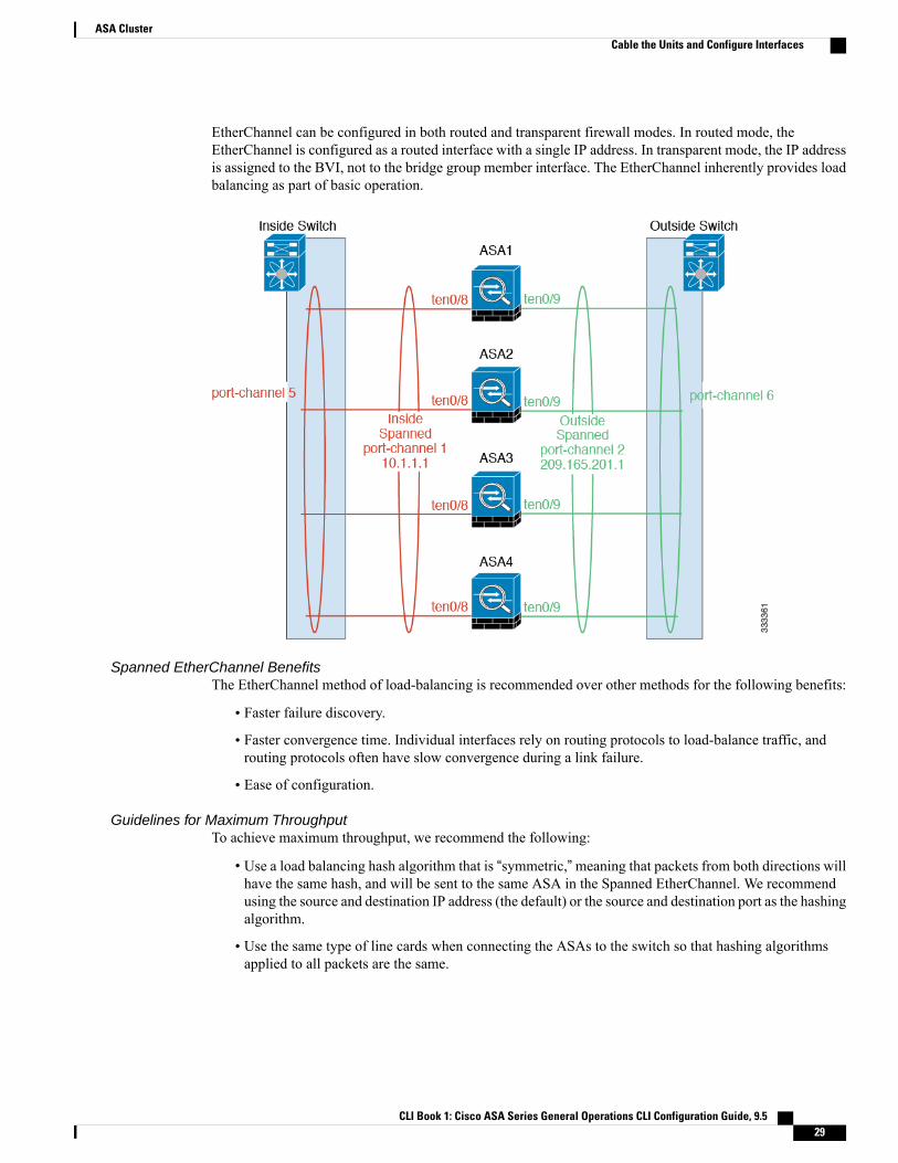
EtherChannel can be configured in both routed and transparent firewall modes. In routed mode, theEtherChannel is configured as a routed interface with a single IP address. In transparent mode, the IP addressis assigned to the BVI, not to the bridge group member interface. The EtherChannel inherently provides loadbalancing as part of basic operation.
Spanned EtherChannel BenefitsThe EtherChannel method of load-balancing is recommended over other methods for the following benefits:
• Faster failure discovery.
• Faster convergence time. Individual interfaces rely on routing protocols to load-balance traffic, androuting protocols often have slow convergence during a link failure.
• Ease of configuration.
Guidelines for Maximum ThroughputTo achieve maximum throughput, we recommend the following:
• Use a load balancing hash algorithm that is “symmetric,”meaning that packets from both directions willhave the same hash, and will be sent to the same ASA in the Spanned EtherChannel. We recommendusing the source and destination IP address (the default) or the source and destination port as the hashingalgorithm.
• Use the same type of line cards when connecting the ASAs to the switch so that hashing algorithmsapplied to all packets are the same.
CLI Book 1: Cisco ASA Series General Operations CLI Configuration Guide, 9.5 29
ASA ClusterCable the Units and Configure Interfaces

Load BalancingThe EtherChannel link is selected using a proprietary hash algorithm, based on source or destination IPaddresses and TCP and UDP port numbers.
On the ASA, do not change the load-balancing algorithm from the default. On the switch, we recommendthat you use one of the following algorithms: source-dest-ip or source-dest-ip-port (see the Cisco NexusOS or Cisco IOS port-channel load-balance command). Do not use a vlan keyword in the load-balancealgorithm because it can cause unevenly distributed traffic to the ASAs in a cluster.
Note
The number of links in the EtherChannel affects load balancing.
Symmetric load balancing is not always possible. If you configure NAT, then forward and return packets willhave different IP addresses and/or ports. Return traffic will be sent to a different unit based on the hash, andthe cluster will have to redirect most returning traffic to the correct unit.
EtherChannel RedundancyThe EtherChannel has built-in redundancy. It monitors the line protocol status of all links. If one link fails,traffic is re-balanced between remaining links. If all links in the EtherChannel fail on a particular unit, butother units are still active, then the unit is removed from the cluster.
Connecting to a VSS or vPCYou can include multiple interfaces per ASA in the Spanned EtherChannel. Multiple interfaces per ASA areespecially useful for connecting to both switches in a VSS or vPC.
Depending on your switches, you can configure up to 32 active links in the spanned EtherChannel. This featurerequires both switches in the vPC to support EtherChannels with 16 active links each (for example the CiscoNexus 7000 with F2-Series 10 Gigabit Ethernet Module).
For switches that support 8 active links in the EtherChannel, you can configure up to 16 active links in thespanned EtherChannel when connecting to two switches in a VSS/vPC.
If you want to use more than 8 active links in a spanned EtherChannel, you cannot also have standby links;the support for 9 to 32 active links requires you to disable cLACP dynamic port priority that allows the useof standby links. You can still use 8 active links and 8 standby links if desired, for example, when connectingto a single switch.
The following figure shows a 32 active link spanned EtherChannel in an 8-ASA cluster and a 16-ASA cluster.
CLI Book 1: Cisco ASA Series General Operations CLI Configuration Guide, 9.530
ASA ClusterCable the Units and Configure Interfaces

The following figure shows a 16 active link spanned EtherChannel in a 4-ASA cluster and an 8-ASA cluster.
CLI Book 1: Cisco ASA Series General Operations CLI Configuration Guide, 9.5 31
ASA ClusterCable the Units and Configure Interfaces

The following figure shows a traditional 8 active/8 standby link spanned EtherChannel in a 4-ASA clusterand an 8-ASA cluster. The active links are shown as solid lines, while the inactive links are dotted. cLACPload-balancing can automatically choose the best 8 links to be active in the EtherChannel. As shown, cLACPhelps achieve load balancing at the link level.
CLI Book 1: Cisco ASA Series General Operations CLI Configuration Guide, 9.532
ASA ClusterCable the Units and Configure Interfaces

Individual Interfaces (Routed Firewall Mode Only)
Individual interfaces are normal routed interfaces, each with their own Local IP address. Because interfaceconfiguration must be configured only on the master unit, the interface configuration lets you set a pool of IPaddresses to be used for a given interface on the cluster members, including one for the master. TheMaincluster IP address is a fixed address for the cluster that always belongs to the current master unit. The Maincluster IP address is a slave IP address for the master unit; the Local IP address is always the master addressfor routing. The Main cluster IP address provides consistent management access to an address; when a masterunit changes, theMain cluster IP address moves to the newmaster unit, so management of the cluster continuesseamlessly. Load balancing, however, must be configured separately on the upstream switch in this case.
We recommend Spanned EtherChannels instead of Individual interfaces because Individual interfacesrely on routing protocols to load-balance traffic, and routing protocols often have slow convergence duringa link failure.
Note
CLI Book 1: Cisco ASA Series General Operations CLI Configuration Guide, 9.5 33
ASA ClusterCable the Units and Configure Interfaces

Policy-Based Routing (Routed Firewall Mode Only)When using Individual interfaces, each ASA interface maintains its own IP address and MAC address. Onemethod of load balancing is Policy-Based Routing (PBR).
We recommend this method if you are already using PBR, and want to take advantage of your existinginfrastructure. This method might offer additional tuning options vs. Spanned EtherChannel as well.
PBR makes routing decisions based on a route map and ACL. You must manually divide traffic between allASAs in a cluster. Because PBR is static, it may not achieve the optimum load balancing result at all times.To achieve the best performance, we recommend that you configure the PBR policy so that forward and returnpackets of a connection are directed to the same physical ASA. For example, if you have a Cisco router,redundancy can be achieved by using Cisco IOS PBR with Object Tracking. Cisco IOS Object Trackingmonitors each ASA using ICMP ping. PBR can then enable or disable route maps based on reachability of aparticular ASA. See the following URLs for more details:
http://www.cisco.com/c/en/us/solutions/data-center-virtualization/intelligent-traffic-director/index.html
http://www.cisco.com/en/US/products/ps6599/products_white_paper09186a00800a4409.shtml
If you use this method of load-balancing, you can use a device-local EtherChannel as an Individualinterface.
Note
Equal-Cost Multi-Path Routing (Routed Firewall Mode Only)When using Individual interfaces, each ASA interface maintains its own IP address and MAC address. Onemethod of load balancing is Equal-Cost Multi-Path (ECMP) routing.
We recommend this method if you are already using ECMP, and want to take advantage of your existinginfrastructure. This method might offer additional tuning options vs. Spanned EtherChannel as well.
CLI Book 1: Cisco ASA Series General Operations CLI Configuration Guide, 9.534
ASA ClusterCable the Units and Configure Interfaces

ECMP routing can forward packets over multiple “best paths” that tie for top place in the routing metric. LikeEtherChannel, a hash of source and destination IP addresses and/or source and destination ports can be usedto send a packet to one of the next hops. If you use static routes for ECMP routing, then an ASA failure cancause problems; the route continues to be used, and traffic to the failed ASA will be lost. If you use staticroutes, be sure to use a static route monitoring feature such as Object Tracking.We recommend using dynamicrouting protocols to add and remove routes, in which case, you must configure each ASA to participate indynamic routing.
If you use this method of load-balancing, you can use a device-local EtherChannel as an Individualinterface.
Note
Nexus Intelligent Traffic Director (Routed Firewall Mode Only)When using Individual interfaces, each ASA interface maintains its own IP address and MAC address.Intelligent Traffic Director (ITD) is a high-speed hardware load-balancing solution for Nexus 5000, 6000,7000, and 9000 switch series. In addition to fully covering the functional capabilities of traditional PBR, itoffers a simplified configuration workflow andmultiple additional features for a more granular load distribution.
ITD supports IP stickiness, consistent hashing for bi-directional flow symmetry, virtual IP addressing, healthmonitoring, sophisticated failure handling policies with N+M redundancy, weighted load-balancing, andapplication IP SLA probes including DNS. Due to the dynamic nature of load-balancing, it achieves a moreeven traffic distribution across all cluster members as compared to PBR. In order to achieve bi-directionalflow symmetry, we recommend configuring ITD such that forward and return packets of a connection aredirected to the same physical ASA. See the following URL for more details:
http://www.cisco.com/c/en/us/solutions/data-center-virtualization/intelligent-traffic-director/index.html
Cable the Cluster Units and Configure Upstream and Downstream EquipmentBefore configuring clustering, cable the cluster control link network, management network, and data networks.
At a minimum, an active cluster control link network is required before you configure the units to jointhe cluster.
Note
You should also configure the upstream and downstream equipment. For example, if you use EtherChannels,then you should configure the upstream and downstream equipment for the EtherChannels.
Examples
This example uses EtherChannels for load-balancing. If you are using PBR or ECMP, your switchconfiguration will differ.
Note
For example on each of 4 ASA 5585-Xs, you want to use:
• 2 Ten Gigabit Ethernet interfaces in a device-local EtherChannel for the cluster control link.
• 2 Ten Gigabit Ethernet interfaces in a Spanned EtherChannel for the inside and outside network; eachinterface is a VLAN subinterface of the EtherChannel. Using subinterfaces lets both inside and outsideinterfaces take advantage of the benefits of an EtherChannel.
CLI Book 1: Cisco ASA Series General Operations CLI Configuration Guide, 9.5 35
ASA ClusterCable the Units and Configure Interfaces

• 1 Management interface.
You have one switch for both the inside and outside networks.
To Switch PortsConnect Interfaces on each of 4 ASAsPurpose
8 ports total
For each TenGigabitEthernet 0/6and TenGigabitEthernet 0/7 pair,configure 4 EtherChannels (1 ECfor each ASA).
These EtherChannels must all beon the same isolated cluster controlVLAN, for example VLAN 101.
TenGigabitEthernet 0/6 andTenGigabitEthernet 0/7
Cluster control link
CLI Book 1: Cisco ASA Series General Operations CLI Configuration Guide, 9.536
ASA ClusterCable the Units and Configure Interfaces

To Switch PortsConnect Interfaces on each of 4 ASAsPurpose
8 ports total
Configure a single EtherChannel(across all ASAs).
On the switch, configure theseVLANs and networks now; forexample, a trunk including VLAN200 for the inside and VLAN 201for the outside.
TenGigabitEthernet 0/8 andTenGigabitEthernet 0/9
Inside and outside interfaces
4 ports total
Place all interfaces on the sameisolated management VLAN, forexample VLAN 100.
Management 0/0Management interface
Configure the Cluster Interface Mode on Each UnitYou can only configure one type of interface for clustering: Spanned EtherChannels or Individual interfaces;you cannot mix interface types in a cluster.
Before You Begin
• You must set the mode separately on each ASA that you want to add to the cluster.
• You can always configure the management-only interface as an Individual interface (recommended),even in Spanned EtherChannel mode. The management interface can be an Individual interface even intransparent firewall mode.
• In Spanned EtherChannel mode, if you configure the management interface as an Individual interface,you cannot enable dynamic routing for the management interface. You must use a static route.
• In multiple context mode, you must choose one interface type for all contexts. For example, if you havea mix of transparent and routedmode contexts, youmust use Spanned EtherChannel mode for all contextsbecause that is the only interface type allowed for transparent mode.
Procedure
Step 1 Show any incompatible configuration so that you can force the interface mode and fix your configurationlater; the mode is not changed with this command:cluster interface-mode {individual | spanned} check-details
Example:
ciscoasa(config)# cluster interface-mode spanned check-details
Step 2 Set the interface mode for clustering:cluster interface-mode {individual | spanned} force
CLI Book 1: Cisco ASA Series General Operations CLI Configuration Guide, 9.5 37
ASA ClusterCable the Units and Configure Interfaces
Example:
ciscoasa(config)# cluster interface-mode spanned force
There is no default setting; you must explicitly choose the mode. If you have not set the mode, you cannotenable clustering.
The force option changes the mode without checking your configuration for incompatible settings. You needto manually fix any configuration issues after you change the mode. Because any interface configuration canonly be fixed after you set the mode, we recommend using the force option so that you can at least start fromthe existing configuration. You can re-run the check-details option after you set the mode for more guidance.
Without the force option, if there is any incompatible configuration, you are prompted to clear yourconfiguration and reload, thus requiring you to connect to the console port to reconfigure your managementaccess. If your configuration is compatible (rare), the mode is changed and the configuration is preserved. Ifyou do not want to clear your configuration, you can exit the command by typing n.
To remove the interface mode, enter the no cluster interface-mode command.
Configure Interfaces on the Master UnitYou must modify any interface that is currently configured with an IP address to be cluster-ready before youenable clustering. For other interfaces, you can configure them before or after you enable clustering; werecommend pre-configuring all of your interfaces so that the complete configuration is synced to new clustermembers.
This section describes how to configure interfaces to be compatible with clustering. You can configure datainterfaces as either Spanned EtherChannels or as Individual interfaces. Each method uses a differentload-balancing mechanism. You cannot configure both types in the same configuration, with the exceptionof the management interface, which can be an Individual interface even in Spanned EtherChannel mode.
Configure Individual Interfaces (Recommended for the Management Interface)
Individual interfaces are normal routed interfaces, each with their own IP address taken from a pool of IPaddresses. The Main cluster IP address is a fixed address for the cluster that always belongs to the currentprimary unit.
In Spanned EtherChannel mode, we recommend configuring the management interface as an Individualinterface. Individual management interfaces let you connect directly to each unit if necessary, while a SpannedEtherChannel interface only allows connection to the current primary unit.
Before You Begin
• Except for the management-only interface, you must be in Individual interface mode.
• For multiple context mode, perform this procedure in each context. If you are not already in the contextconfiguration mode, enter the changeto context name command.
• Individual interfaces require you to configure load balancing on neighbor devices. External load balancingis not required for the management interface.
• (Optional) Configure the interface as a device-local EtherChannel interface, a redundant interface, and/orconfigure subinterfaces.
CLI Book 1: Cisco ASA Series General Operations CLI Configuration Guide, 9.538
ASA ClusterCable the Units and Configure Interfaces

◦For an EtherChannel, this EtherChannel is local to the unit, and is not a Spanned EtherChannel.
◦Management-only interfaces cannot be redundant interfaces.
Procedure
Step 1 Configure a pool of Local IP addresses (IPv4 and/or IPv6), one of which will be assigned to each cluster unitfor the interface:(IPv4)
ip local pool poolname first-address— last-address [mask mask]
(IPv6)
ipv6 local pool poolname ipv6-address/prefix-length number_of_addresses
Example:
ciscoasa(config)# ip local pool ins 192.168.1.2-192.168.1.9ciscoasa(config-if)# ipv6 local pool insipv6 2001:DB8::1002/32 8
Include at least as many addresses as there are units in the cluster. If you plan to expand the cluster, includeadditional addresses. The Main cluster IP address that belongs to the current primary unit is not a part of thispool; be sure to reserve an IP address on the same network for the Main cluster IP address.
You cannot determine the exact Local address assigned to each unit in advance; to see the address used oneach unit, enter the show ip[v6] local pool poolname command. Each cluster member is assigned a memberID when it joins the cluster. The ID determines the Local IP used from the pool.
Step 2 Enter interface configuration mode:interface interface_id
Example:
ciscoasa(config)# interface tengigabitethernet 0/8
Step 3 (Management interface only) Set an interface to management-only mode so that it does not pass throughtraffic:management-only
By default, Management type interfaces are configured as management-only. In transparent mode, thiscommand is always enabled for a Management type interface.
This setting is required if the cluster interface mode is Spanned.
Step 4 Name the interface:nameif name
Example:
ciscoasa(config-if)# nameif inside
The name is a text string up to 48 characters, and is not case-sensitive. You can change the name by reenteringthis command with a new value.
CLI Book 1: Cisco ASA Series General Operations CLI Configuration Guide, 9.5 39
ASA ClusterCable the Units and Configure Interfaces

Step 5 Set the Main cluster IP address and identify the cluster pool:(IPv4)
ip address ip_address [mask] cluster-pool poolname
(IPv6)
ipv6 address ipv6-address/prefix-length cluster-pool poolname
Example:
ciscoasa(config-if)# ip address 192.168.1.1 255.255.255.0 cluster-pool insciscoasa(config-if)# ipv6 address 2001:DB8::1002/32 cluster-pool insipv6
This IP address must be on the same network as the cluster pool addresses, but not be part of the pool. Youcan configure an IPv4 and/or an IPv6 address.
DHCP, PPPoE, and IPv6 autoconfiguration are not supported; you must manually configure the IP addresses.
Step 6 Set the security level, where number is an integer between 0 (lowest) and 100 (highest):security-level number
Example:
ciscoasa(config-if)# security-level 100
Step 7 Enable the interface:no shutdown
Examples
The following example configures the Management 0/0 and Management 0/1 interfaces as a device-localEtherChannel, and then configures the EtherChannel as an Individual interface:
ip local pool mgmt 10.1.1.2-10.1.1.9ipv6 local pool mgmtipv6 2001:DB8:45:1002/64 8interface management 0/0
channel-group 1 mode activeno shutdown
interface management 0/1
channel-group 1 mode activeno shutdown
interface port-channel 1
nameif managementip address 10.1.1.1 255.255.255.0 cluster-pool mgmtipv6 address 2001:DB8:45:1001/64 cluster-pool mgmtipv6security-level 100management-only
CLI Book 1: Cisco ASA Series General Operations CLI Configuration Guide, 9.540
ASA ClusterCable the Units and Configure Interfaces

Configure Spanned EtherChannels
ASpanned EtherChannel spans all ASAs in the cluster, and provides load balancing as part of the EtherChanneloperation.
Before You Begin
• You must be in Spanned EtherChannel interface mode.
• For multiple context mode, start this procedure in the system execution space. If you are not already inthe System configuration mode, enter the changeto system command.
• For transparent mode, configure the bridge group.
• Do not specify the maximum and minimum links in the EtherChannel—We recommend that you do notspecify themaximum andminimum links in the EtherChannel (The lacpmax-bundle and port-channelmin-bundle commands) on either the ASA or the switch. If you need to use them, note the following:
◦The maximum links set on the ASA is the total number of active ports for the whole cluster. Besure the maximum links value configured on the switch is not larger than the ASA value.
◦Theminimum links set on the ASA is the minimum active ports to bring up a port-channel interfaceper unit. On the switch, the minimum links is the minimum links across the cluster, so this valuewill not match the ASA value.
• Do not change the load-balancing algorithm from the default (see the port-channel load-balancecommand). On the switch, we recommend that you use one of the following algorithms: source-dest-ipor source-dest-ip-port (see the Cisco Nexus OS and Cisco IOS port-channel load-balance command).Do not use a vlan keyword in the load-balance algorithm because it can cause unevenly distributedtraffic to the ASAs in a cluster.
• The lacp port-priority and lacp system-priority commands are not used for a Spanned EtherChannel.
•When using Spanned EtherChannels, the port-channel interface will not come up until clustering is fullyenabled. This requirement prevents traffic from being forwarded to a unit that is not an active unit inthe cluster.
Procedure
Step 1 Specify the interface you want to add to the channel group:interface physical_interface
Example:
ciscoasa(config)# interface gigabitethernet 0/0
The physical_interface ID includes the type, slot, and port number as type slot/port. This first interface in thechannel group determines the type and speed for all other interfaces in the group.
Step 2 Assign this interface to an EtherChannel:channel-group channel_id mode active [vss-id {1 | 2}]
CLI Book 1: Cisco ASA Series General Operations CLI Configuration Guide, 9.5 41
ASA ClusterCable the Units and Configure Interfaces

Example:
ciscoasa(config-if)# channel-group 1 mode active
The channel_id is between 1 and 48. If the port-channel interface for this channel ID does not yet exist in theconfiguration, one will be added automatically:
interface port-channel channel_id
Only active mode is supported for Spanned EtherChannels.
If you are connecting the ASA to two switches in a VSS or vPC, then configure the vss-id keyword to identifyto which switch this interface is connected (1 or 2). You must also use the port-channel span-clustervss-load-balance command for the port-channel interface in Step 6.
Step 3 Enable the interface:no shutdown
Step 4 (Optional) Add additional interfaces to the EtherChannel by repeating the process.
Example:
ciscoasa(config)# interface gigabitethernet 0/1ciscoasa(config-if)# channel-group 1 mode activeciscoasa(config-if)# no shutdown
Multiple interfaces in the EtherChannel per unit are useful for connecting to switches in a VSS or vPC. Keepin mind that by default, a spanned EtherChannel can have only 8 active interfaces out of 16 maximum acrossall members in the cluster; the remaining 8 interfaces are on standby in case of link failure. To use more than8 active interfaces (but no standby interfaces), disable dynamic port priority using the clacp static-port-prioritycommand. When you disable dynamic port priority, you can use up to 32 active links across the cluster. Forexample, for a cluster of 16 ASAs, you can use a maximum of 2 interfaces on each ASA, for a total of 32interfaces in the spanned EtherChannel.
Step 5 Specify the port-channel interface:interface port-channel channel_id
Example:
ciscoasa(config)# interface port-channel 1
This interface was created automatically when you added an interface to the channel group.
Step 6 Set this EtherChannel as a Spanned EtherChannel:port-channel span-cluster [vss-load-balance]
Example:
ciscoasa(config-if)# port-channel span-cluster
If you are connecting the ASA to two switches in a VSS or vPC, then you should enable VSS load balancingby using the vss-load-balance keyword. This feature ensures that the physical link connections between theASAs to the VSS (or vPC) pair are balanced. You must configure the vss-id keyword in the channel-groupcommand for each member interface before enabling load balancing (see Step 2).
CLI Book 1: Cisco ASA Series General Operations CLI Configuration Guide, 9.542
ASA ClusterCable the Units and Configure Interfaces

Step 7 (Optional) You can set the Ethernet properties for the port-channel interface to override the properties set onthe Individual interfaces.This method provides a shortcut to set these parameters because these parameters must match for all interfacesin the channel group.
Step 8 (Optional) If you are creating VLAN subinterfaces on this EtherChannel, do so now.
Example:
ciscoasa(config)# interface port-channel 1.10ciscoasa(config-if)# vlan 10
The rest of this procedure applies to the subinterfaces.
Step 9 (Multiple Context Mode) Allocate the interface to a context. Then enter:changeto context nameinterface port-channel channel_id
Example:
ciscoasa(config)# context adminciscoasa(config)# allocate-interface port-channel1ciscoasa(config)# changeto context adminciscoasa(config-if)# interface port-channel 1
For multiple context mode, the rest of the interface configuration occurs within each context.
Step 10 Name the interface:nameif name
Example:
ciscoasa(config-if)# nameif inside
The name is a text string up to 48 characters, and is not case-sensitive. You can change the name by reenteringthis command with a new value.
Step 11 Perform one of the following, depending on the firewall mode.
• Routed Mode—Set the IPv4 and/or IPv6 address:
(IPv4)
ip address ip_address [mask]
(IPv6)
ipv6 address ipv6-prefix/prefix-length
Example:
ciscoasa(config-if)# ip address 10.1.1.1 255.255.255.0ciscoasa(config-if)# ipv6 address 2001:DB8::1001/32
DHCP, PPPoE, and IPv6 autoconfig are not supported.
• Transparent Mode—Assign the interface to a bridge group:
CLI Book 1: Cisco ASA Series General Operations CLI Configuration Guide, 9.5 43
ASA ClusterCable the Units and Configure Interfaces

bridge-group number
Example:
ciscoasa(config-if)# bridge-group 1
Where number is an integer between 1 and 100. You can assign up to 4 interfaces to a bridge group.You cannot assign the same interface to more than one bridge group. Note that the BVI configurationincludes the IP address.
Step 12 Set the security level:security-level number
Example:
ciscoasa(config-if)# security-level 50
Where number is an integer between 0 (lowest) and 100 (highest).
Step 13 Configure a globalMAC address for a Spanned EtherChannel to avoid potential network connectivity problems:mac-address mac_address
Example:
ciscoasa(config-if)# mac-address 000C.F142.4CDE
With a manually-configured MAC address, the MAC address stays with the current primary unit. In multiplecontext mode, if you share an interface between contexts, you should enable auto-generation ofMAC addressesso that you only need to set the MAC address manually for a shared interface if you disable auto-generation.Note that you must manually configure the MAC address for non-shared interfaces.
The mac_address is in H.H.H format, where H is a 16-bit hexadecimal digit. For example, the MAC address00-0C-F1-42-4C-DE is entered as 000C.F142.4CDE.
The first two bytes of a manual MAC address cannot be A2 if you also want to use auto-generated MACaddresses.
Step 14 (Routed mode) For inter-site clustering, configure a site-specific MAC address for each site:mac-address mac_address site-id number
Example:
ciscoasa(config-if)# mac-address aaaa.1111.1234ciscoasa(config-if)# mac-address aaaa.1111.aaaa site-id 1ciscoasa(config-if)# mac-address aaaa.1111.bbbb site-id 2ciscoasa(config-if)# mac-address aaaa.1111.cccc site-id 3ciscoasa(config-if)# mac-address aaaa.1111.dddd site-id 4
The site-specific MAC address used by a unit depends on the site ID you specify in each unit’s bootstrapconfiguration.
CLI Book 1: Cisco ASA Series General Operations CLI Configuration Guide, 9.544
ASA ClusterCable the Units and Configure Interfaces

Create the Bootstrap ConfigurationEach unit in the cluster requires a bootstrap configuration to join the cluster.
Configure the Master Unit Bootstrap SettingsEach unit in the cluster requires a bootstrap configuration to join the cluster. Typically, the first unit youconfigure to join the cluster will be the master unit. After you enable clustering, after an election period, thecluster elects a master unit. With only one unit in the cluster initially, that unit will become the master unit.Subsequent units that you add to the cluster will be slave units.
Before You Begin
• Back up your configurations in case you later want to leave the cluster, and need to restore yourconfiguration.
• For multiple context mode, complete these procedures in the system execution space. To change fromthe context to the system execution space, enter the changeto system command.
•We recommend enabling jumbo frame reservation for use with the cluster control link.
• You must use the console port to enable or disable clustering. You cannot use Telnet or SSH.
•With the exception of the cluster control link, any interfaces in your configuration must be configuredwith a cluster IP pool or as a Spanned EtherChannel before you enable clustering, depending on yourinterface mode. If you have pre-existing interface configuration, you can either clear the interfaceconfiguration (clear configure interface), or convert your interfaces to cluster interfaces before youenable clustering.
•When you add a unit to a running cluster, you may see temporary, limited packet/connection drops; thisis expected behavior.
• Pre-determine the size of the cluster control link. See Size the Cluster Control Link, on page 27.
Procedure
Step 1 Enable the cluster control link interface before you join the cluster.You will later identify this interface as the cluster control link when you enable clustering.
We recommend that you combine multiple cluster control link interfaces into an EtherChannel if you haveenough interfaces. The EtherChannel is local to the ASA, and is not a Spanned EtherChannel.
The cluster control link interface configuration is not replicated from the master unit to slave units; however,you must use the same configuration on each unit. Because this configuration is not replicated, you mustconfigure the cluster control link interfaces separately on each unit.
• You cannot use a VLAN subinterface as the cluster control link.
• You cannot use aManagement x/x interface as the cluster control link, either alone or as an EtherChannel.
• For the ASA 5585-Xwith anASAFirePOWERmodule, Cisco recommends that you use ASA interfacesfor the cluster control link, and not interfaces on the ASA FirePOWER module. Module interfaces candrop traffic for up to 30 seconds during a module reload, including reloads that occur during a softwareupgrade. However, if needed, you can use module interfaces and ASA interfaces in the same cluster
CLI Book 1: Cisco ASA Series General Operations CLI Configuration Guide, 9.5 45
ASA ClusterCreate the Bootstrap Configuration

control link EtherChannel.When themodule interfaces drop, the remaining interfaces in the EtherChannelare still up. The ASA 5585-X Network Module does not run a separate operating system, so it is notaffected by this issue.
a) Enter interface configuration mode:interface interface_id
Example:
ciscoasa(config)# interface tengigabitethernet 0/6
b) (Optional, for an EtherChannel) Assign this physical interface to an EtherChannel:channel-group channel_id mode on
Example:
ciscoasa(config-if)# channel-group 1 mode on
The channel_id is between 1 and 48. If the port-channel interface for this channel ID does not yet exist inthe configuration, one will be added automatically:
interface port-channel channel_id
We recommend using the Onmode for cluster control link member interfaces to reduce unnecessary trafficon the cluster control link. The cluster control link does not need the overhead of LACP traffic because itis an isolated, stable network. Note:We recommend setting data EtherChannels to Active mode.
c) Enable the interface:no shutdown
You only need to enable the interface; do not configure a name for the interface, or any other parameters.
d) (For an EtherChannel) Repeat for each additional interface you want to add to the EtherChannel:
Example:
ciscoasa(config)# interface tengigabitethernet 0/7ciscoasa(config-if)# channel-group 1 mode onciscoasa(config-if)# no shutdown
Step 2 (Optional) Specify the maximum transmission unit for the cluster control link interface:mtu cluster bytes
Example:
ciscoasa(config)# mtu cluster 9000
Set the MTU between 1400 and 9198 bytes. The default MTU is 1500 bytes.
We suggest setting the MTU to 1600 bytes or greater, which requires you to enable jumbo frame reservationbefore continuing with this procedure. Jumbo frame reservation requires a reload of the ASA.
This command is a global configuration command, but is also part of the bootstrap configuration that is notreplicated between units.
Step 3 Name the cluster and enter cluster configuration mode:
CLI Book 1: Cisco ASA Series General Operations CLI Configuration Guide, 9.546
ASA ClusterCreate the Bootstrap Configuration

cluster group name
Example:
ciscoasa(config)# cluster group pod1
The name must be an ASCII string from 1 to 38 characters. You can only configure one cluster group perunit. All members of the cluster must use the same name.
Step 4 Name this member of the cluster:local-unit unit_name
Use a unique ASCII string from 1 to 38 characters. Each unit must have a unique name. A unit with a duplicatedname will be not be allowed in the cluster.
Example:
ciscoasa(cfg-cluster)# local-unit unit1
Step 5 Specify the cluster control link interface, preferably an EtherChannel:cluster-interface interface_id ip ip_address mask
Example:
ciscoasa(cfg-cluster)# cluster-interface port-channel2 ip 192.168.1.1 255.255.255.0INFO: Non-cluster interface config is cleared on Port-Channel2
Subinterfaces and Management interfaces are not allowed.
Specify an IPv4 address for the IP address; IPv6 is not supported for this interface. This interface cannot havea nameif configured.
For each unit, specify a different IP address on the same network.
Step 6 If you use inter-site clustering, set the site ID for this unit so it uses a site-specific MAC address:site-id number
Example:
ciscoasa(cfg-cluster)# site-id 1
The number is between 1 and 8.
Step 7 Set the priority of this unit for master unit elections:priority priority_number
Example:
ciscoasa(cfg-cluster)# priority 1
The priority is between 1 and 100, where 1 is the highest priority.
Step 8 (Optional) Set an authentication key for control traffic on the cluster control link:key shared_secret
CLI Book 1: Cisco ASA Series General Operations CLI Configuration Guide, 9.5 47
ASA ClusterCreate the Bootstrap Configuration

Example:
ciscoasa(cfg-cluster)# key chuntheunavoidable
The shared secret is an ASCII string from 1 to 63 characters. The shared secret is used to generate the key.This command does not affect datapath traffic, including connection state update and forwarded packets,which are always sent in the clear.
Step 9 (Optional) Disable dynamic port priority in LACP:clacp static-port-priority
Some switches do not support dynamic port priority, so this command improves switch compatibility.Moreover,it enables support of more than 8 active spanned EtherChannel members, up to 32 members. Without thiscommand, only 8 active members and 8 standby members are supported. If you enable this command, thenyou cannot use any standby members; all members are active.
Step 10 (Optional) Manually specify the cLACP system ID and system priority:clacp system-mac {mac_address | auto} [system-priority number]
Example:
ciscoasa(cfg-cluster)# clacp system-mac 000a.0000.aaaa
When using Spanned EtherChannels, the ASA uses cLACP to negotiate the EtherChannel with the neighborswitch. ASAs in a cluster collaborate in cLACP negotiation so that they appear as a single (virtual) device tothe switch. One parameter in cLACP negotiation is a system ID, which is in the format of a MAC address.All ASAs in the cluster use the same system ID: auto-generated by the master unit (the default) and replicatedto all secondaries; or manually specified in this command in the formH.H.H, where H is a 16-bit hexadecimaldigit. (For example, the MAC address 00-0A-00-00-AA-AA is entered as 000A.0000.AAAA.) You mightwant to manually configure the MAC address for troubleshooting purposes, for example, so that you can usean easily identified MAC address. Typically, you would use the auto-generated MAC address.
The system priority, between 1 and 65535, is used to decide which unit is in charge of making a bundlingdecision. By default, the ASA uses priority 1, which is the highest priority. The priority needs to be higherthan the priority on the switch.
This command is not part of the bootstrap configuration, and is replicated from the master unit to the slaveunits. However, you cannot change this value after you enable clustering.
Step 11 Enable clustering:enable [noconfirm]
Example:
ciscoasa(cfg-cluster)# enableINFO: Clustering is not compatible with following commands:policy-map global_policyclass inspection_defaultinspect skinnypolicy-map global_policyclass inspection_defaultinspect sipWould you like to remove these commands? [Y]es/[N]o:Y
INFO: Removing incompatible commands from running configuration...Cryptochecksum (changed): f16b7fc2 a742727e e40bc0b0 cd169999
CLI Book 1: Cisco ASA Series General Operations CLI Configuration Guide, 9.548
ASA ClusterCreate the Bootstrap Configuration

INFO: Done
When you enter the enable command, the ASA scans the running configuration for incompatible commandsfor features that are not supported with clustering, including commands that may be present in the defaultconfiguration. You are prompted to delete the incompatible commands. If you respond No, then clustering isnot enabled. Use the noconfirm keyword to bypass the confirmation and delete incompatible commandsautomatically.
For the first unit enabled, a master unit election occurs. Because the first unit should be the only member ofthe cluster so far, it will become the master unit. Do not perform any configuration changes during this period.
To disable clustering, enter the no enable command.
If you disable clustering, all data interfaces are shut down, and only the management-only interfaceis active.
Note
Examples
The following example configures a management interface, configures a device-local EtherChannel for thecluster control link, and then enables clustering for the ASA called “unit1,”which will become the master unitbecause it is added to the cluster first:
ip local pool mgmt 10.1.1.2-10.1.1.9ipv6 local pool mgmtipv6 2001:DB8::1002/32 8interface management 0/0
nameif managementip address 10.1.1.1 255.255.255.0 cluster-pool mgmtipv6 address 2001:DB8::1001/32 cluster-pool mgmtipv6security-level 100management-onlyno shutdown
interface tengigabitethernet 0/6channel-group 1 mode onno shutdown
interface tengigabitethernet 0/7channel-group 1 mode onno shutdown
cluster group pod1local-unit unit1cluster-interface port-channel1 ip 192.168.1.1 255.255.255.0priority 1key chuntheunavoidableenable noconfirm
Configure Slave Unit Bootstrap SettingsPerform the following procedure to configure the slave units.
Before You Begin
• You must use the console port to enable or disable clustering. You cannot use Telnet or SSH.
• Back up your configurations in case you later want to leave the cluster, and need to restore yourconfiguration.
CLI Book 1: Cisco ASA Series General Operations CLI Configuration Guide, 9.5 49
ASA ClusterCreate the Bootstrap Configuration

• For multiple context mode, complete this procedure in the system execution space. To change from thecontext to the system execution space, enter the changeto system command.
•We recommend enabling jumbo frame reservation for use with the cluster control link.
• If you have any interfaces in your configuration that have not been configured for clustering (for example,the default configuration Management 0/0 interface), you can join the cluster as a slave unit (with nopossibility of becoming the master in a current election).
•When you add a unit to a running cluster, you may see temporary, limited packet/connection drops; thisis expected behavior.
Procedure
Step 1 Configure the same cluster control link interface as you configured for the master unit.
Example:
ciscoasa(config)# interface tengigabitethernet 0/6ciscoasa(config-if)# channel-group 1 mode onciscoasa(config-if)# no shutdownciscoasa(config)# interface tengigabitethernet 0/7ciscoasa(config-if)# channel-group 1 mode onciscoasa(config-if)# no shutdown
Step 2 Specify the same MTU that you configured for the master unit:
Example:
ciscoasa(config)# mtu cluster 9000
Step 3 Identify the same cluster name that you configured for the master unit:
Example:
ciscoasa(config)# cluster group pod1
Step 4 Name this member of the cluster with a unique string:local-unit unit_name
Example:
ciscoasa(cfg-cluster)# local-unit unit2
Specify an ASCII string from 1 to 38 characters.
Each unit must have a unique name. A unit with a duplicated name will be not be allowed in the cluster.
Step 5 Specify the same cluster control link interface that you configured for the master unit, but specify a differentIP address on the same network for each unit:cluster-interface interface_id ip ip_address mask
Example:
ciscoasa(cfg-cluster)# cluster-interface port-channel2 ip 192.168.1.2 255.255.255.0
CLI Book 1: Cisco ASA Series General Operations CLI Configuration Guide, 9.550
ASA ClusterCreate the Bootstrap Configuration

INFO: Non-cluster interface config is cleared on Port-Channel2
Specify an IPv4 address for the IP address; IPv6 is not supported for this interface. This interface cannot havea nameif configured.
Each unit must have a unique name. A unit with a duplicated name will not be allowed in the cluster.
Step 6 If you use inter-site clustering, set the site ID for this unit so it uses a site-specific MAC address:site-id number
Example:
ciscoasa(cfg-cluster)# site-id 1
The number is between 1 and 8.
Step 7 Set the priority of this unit for master unit elections, typically to a higher value than the master unit:priority priority_number
Example:
ciscoasa(cfg-cluster)# priority 2
Set the priority between 1 and 100, where 1 is the highest priority.
Step 8 Set the same authentication key that you set for the master unit:
Example:
ciscoasa(cfg-cluster)# key chuntheunavoidable
Step 9 Enable clustering:enable as-slave
You can avoid any configuration incompatibilities (primarily the existence of any interfaces not yet configuredfor clustering) by using the enable as-slave command. This command ensures the slave joins the cluster withno possibility of becoming the master in any current election. Its configuration is overwritten with the onesynced from the master unit.
To disable clustering, enter the no enable command.
If you disable clustering, all data interfaces are shut down, and only the management interface isactive.
Note
Examples
The following example includes the configuration for a slave unit, unit2:
interface tengigabitethernet 0/6
channel-group 1 mode onno shutdown
interface tengigabitethernet 0/7
channel-group 1 mode onno shutdown
CLI Book 1: Cisco ASA Series General Operations CLI Configuration Guide, 9.5 51
ASA ClusterCreate the Bootstrap Configuration

cluster group pod1
local-unit unit2cluster-interface port-channel1 ip 192.168.1.2 255.255.255.0priority 2key chuntheunavoidableenable as-slave
Customize the Clustering OperationYou can customize clustering health monitoring, TCP connection replication delay, flow mobility and otheroptimizations.
Perform these procedures on the master unit.
Configure Basic ASA Cluster ParametersYou can customize cluster settings on the master unit.
Before You Begin
• For multiple context mode, complete this procedure in the system execution space on the master unit.To change from the context to the system execution space, enter the changeto system command.
Procedure
Step 1 Enter cluster configuration mode:cluster group name
Step 2 (Optional) Enable console replication from slave units to the master unit:console-replicate
This feature is disabled by default. The ASA prints out some messages directly to the console for certaincritical events. If you enable console replication, slave units send the console messages to the master unit sothat you only need to monitor one console port for the cluster.
Step 3 Set the minimum trace level for clustering events:trace-level level
Set the minimum level as desired:
• critical—Critical events (severity=1)
• warning—Warnings (severity=2)
• informational—Informational events (severity=3)
• debug—Debugging events (severity=4)
CLI Book 1: Cisco ASA Series General Operations CLI Configuration Guide, 9.552
ASA ClusterCustomize the Clustering Operation

Configure Health Monitoring and Auto-Rejoin SettingsThis procedure configures unit and interface health monitoring.
You might want to disable health monitoring of non-essential interfaces, for example, the managementinterface. You can monitor any port-channel ID, redundant ID, or single physical interface ID, or the softwareor hardware module, such as the ASA Firepower module. Health monitoring is not performed on VLANsubinterfaces or virtual interfaces such as VNIs or BVIs. You cannot configure monitoring for the clustercontrol link; it is always monitored.
Procedure
Step 1 Enter cluster configuration mode.cluster group name
Example:
ciscoasa(config)# cluster group testciscoasa(cfg-cluster)#
Step 2 Customize the cluster unit health check feature.health-check [holdtime timeout] [vss-enabled]
To determine unit health, the ASA cluster units send keepalive messages on the cluster control link to otherunits. If a unit does not receive any keepalive messages from a peer unit within the holdtime period, the peerunit is considered unresponsive or dead.
• holdtime timeout—Determines the amount of time between unit keepalive status messages, between .8and 45 seconds; The default is 3 seconds.
• vss-enabled—Floods the keepalive messages on all EtherChannel interfaces in the cluster control linkto ensure that at least one of the switches can receive them. If you configure the cluster control link asan EtherChannel (recommended), and it is connected to a VSS or vPC pair, then you might need toenable the vss-enabled option. For some switches, when one unit in the VSS/vPC is shutting down orbooting up, EtherChannel member interfaces connected to that switch may appear to be Up to the ASA,but they are not passing traffic on the switch side. The ASA can be erroneously removed from the clusterif you set the ASA holdtime timeout to a low value (such as .8 seconds), and the ASA sends keepalivemessages on one of these EtherChannel interfaces.
When any topology changes occur (such as adding or removing a data interface, enabling or disabling aninterface on the ASA or the switch, or adding an additional switch to form a VSS or vPC) you should disablethe health check feature and also disable interface monitoring for the disabled interfaces (no health-checkmonitor-interface). When the topology change is complete, and the configuration change is synced to allunits, you can re-enable the health check feature.
Example:
ciscoasa(cfg-cluster)# health-check holdtime 5
Step 3 Disable the interface health check on an interface.no health-check monitor-interface [interface_id | service-module]
CLI Book 1: Cisco ASA Series General Operations CLI Configuration Guide, 9.5 53
ASA ClusterCustomize the Clustering Operation

The interface health check monitors for link failures. If all physical ports for a given logical interface fail ona particular unit, but there are active ports under the same logical interface on other units, then the unit isremoved from the cluster. The amount of time before the ASA removes a member from the cluster dependson the type of interface and whether the unit is an established member or is joining the cluster. Health checkis enabled by default for all interfaces. You can disable it per interface using the no form of this command.You might want to disable health monitoring of non-essential interfaces, for example, the managementinterface.
• interface_id—Disables monitoring of any port-channel ID, redundant ID, or single physical interfaceID. Health monitoring is not performed on VLAN subinterfaces or virtual interfaces such as VNIs orBVIs. You cannot configure monitoring for the cluster control link; it is always monitored.
• service-module—Disablesmonitoring of a hardware or softwaremodule, such as the ASAFirePOWERmodule. Note that for the ASA 5585-X, if you disable monitoring of the service module, you may alsowant to disable monitoring of the interfaces on the module, which are monitored separately.
When any topology changes occur (such as adding or removing a data interface, enabling or disabling aninterface on the ASA or the switch, or adding an additional switch to form a VSS or vPC) you should disablethe health check feature (no health-check) and also disable interface monitoring for the disabled interfaces.When the topology change is complete, and the configuration change is synced to all units, you can re-enablethe health check feature.
Example:
ciscoasa(cfg-cluster)# no health-check monitor-interface management0/0
Step 4 Customize the auto-rejoin cluster settings after a health check failure.health-check {data-interface | cluster-interface} auto-rejoin {unlimited | auto_rejoin_max}[auto_rejoin_interval [auto_rejoin_interval_variation]]
• unlimited—(Default for the cluster-interface) Does not limit the number of rejoin attempts.
• auto-rejoin-max—Sets the number of rejoin attempts, between 0 and 65535. 0 disables auto-rejoining.The default for the data-interface is 3.
• auto_rejoin_interval—Defines the interval duration in minutes between rejoin attempts, between 2 and60. The default value is 5 minutes. The maximum total time that the unit attempts to rejoin the clusteris limited to 14400 minutes (10 days) from the time of last failure.
• auto_rejoin_interval_variation—Defines if the interval duration increases. Set the value between 1 and3: 1 (no change); 2 (2 x the previous duration), or 3 (3 x the previous duration). For example, if you setthe interval duration to 5 minutes, and set the variation to 2, then the first attempt is after 5 minutes; the2nd attempt is 10 minutes (2 x 5); the 3rd attempt 20 minutes (2 x 10), and so on. The default value is1 for the cluster-interface and 2 for the data-interface.
Example:
ciscoasa(cfg-cluster)# health-check data-interface auto-rejoin 10 3 3
CLI Book 1: Cisco ASA Series General Operations CLI Configuration Guide, 9.554
ASA ClusterCustomize the Clustering Operation

Example
The following example configures the health-check holdtime to .3 seconds; enables VSS; disables monitoringon the Ethernet 1/2 interface, which is used for management; sets the auto-rejoin for data interfaces to 4attempts starting at 2 minutes, increasing the duration by 3 x the previous interval; and sets the auto-rejoinfor the cluster control link to 6 attempts every 2 minutes.
ciscoasa(config)# cluster group testciscoasa(cfg-cluster)# health-check holdtime .3 vss-enabledciscoasa(cfg-cluster)# no health-check monitor-interface ethernet1/2ciscoasa(cfg-cluster)# health-check data-interface auto-rejoin 4 2 3ciscoasa(cfg-cluster)# health-check cluster-interface auto-rejoin 6 2 1
Configure Connection Rebalancing and the Cluster TCP Replication DelayYou can configure connection rebalancing. For more information, see Rebalancing New TCP ConnectionsAcross the Cluster, on page 10
Enable the cluster replication delay for TCP connections to help eliminate the “unnecessary work” related toshort-lived flows by delaying the director/backup flow creation. Note that if a unit fails before thedirector/backup flow is created, then those flows cannot be recovered. Similarly, if traffic is rebalanced to adifferent unit before the flow is created, then the flow cannot be recovered. You should not enable the TCPreplication delay for traffic on which you disable TCP randomization.
Procedure
Step 1 Enable the cluster replication delay for TCP connections:cluster replication delay seconds {http | match tcp {host ip_address | ip_address mask | any | any4 | any6}[{eq | lt | gt} port] {host ip_address | ip_address mask | any | any4 | any6} [{eq | lt | gt} port]}
Example:
ciscoasa(config)# cluster replication delay 15 match tcp any any eq ftpciscoasa(config)# cluster replication delay 15 http
Set the seconds between 1 and 15. The http delay is enabled by default for 5 seconds.
In multiple context mode, configure this setting within the context.
Step 2 Enter cluster configuration mode:cluster group name
Step 3 (Optional) Enable connection rebalancing for TCP traffic:conn-rebalance [frequency seconds]
Example:
ciscoasa(cfg-cluster)# conn-rebalance frequency 60
This command is disabled by default. If enabled, ASAs exchange load information periodically, and offloadnew connections frommore loaded devices to less loaded devices. The frequency, between 1 and 360 seconds,specifies how often the load information is exchanged. The default is 5 seconds.
CLI Book 1: Cisco ASA Series General Operations CLI Configuration Guide, 9.5 55
ASA ClusterCustomize the Clustering Operation

Do not configure connection rebalancing for inter-site topologies; you do not want connections rebalancedto cluster members at a different site.
Configure Cluster Flow MobilityYou can inspect LISP traffic to enable flow mobility when a server moves between sites.
About LISP Inspection
You can inspect LISP traffic to enable flow mobility between sites.
About LISPData center virtual machine mobility such as VMware VMotion enables servers to migrate between datacenters while maintaining connections to clients. To support such data center server mobility, routers need tobe able to update the ingress route towards the server when it moves. Cisco Locator/ID Separation Protocol(LISP) architecture separates the device identity, or endpoint identifier (EID), from its location, or routinglocator (RLOC), into two different numbering spaces, making server migration transparent to clients. Forexample, when a server moves to a new site and a client sends traffic to the server, the router redirects trafficto the new location.
LISP requires routers and servers in certain roles, such as the LISP egress tunnel router (ETR), ingress tunnelrouter (ITR), first hop routers, map resolver (MR), and map server (MS). When the first hop router for theserver senses that the server is connected to a different router, it updates all of the other routers and databasesso that the ITR connected to the client can intercept, encapsulate, and send traffic to the new server location.
ASA LISP SupportThe ASA does not run LISP itself; it can, however, inspect LISP traffic for location changes and then use thisinformation for seamless clustering operation. Without LISP integration, when a server moves to a new site,traffic comes to an ASA cluster member at the new site instead of to the original flow owner. The new ASAforwards traffic to the ASA at the old site, and then the old ASA has to send traffic back to the new site toreach the server. This traffic flow is sub-optimal and is known as “tromboning” or “hair-pinning.”With LISP integration, the ASA cluster members can inspect LISP traffic passing between the first hop routerand the ETR or ITR, and can then change the flow owner to be at the new site.
LISP Guidelines
• The ASA cluster members must reside between the first hop router and the ITR or ETR for the site. TheASA cluster itself cannot be the first hop router for an extended segment.
• Only fully-distributed flows are supported; centralized flows, semi-distributed flows, or flows belongingto individual units are not moved to new owners. Semi-distributed flows include applications, such asSIP, where all child flows are owned by the same ASA that owns the parent flow.
• The cluster only moves Layer 3 and 4 flow states; some application data might be lost.
• For short-lived flows or non-business-critical flows, moving the owner may not be worthwhile. Youcan control the types of traffic that are supported with this feature when you configure the inspectionpolicy, and should limit flow mobility to essential traffic.
ASA LISP ImplementationThis feature includes several inter-related configurations (all of which are described in this chapter):
CLI Book 1: Cisco ASA Series General Operations CLI Configuration Guide, 9.556
ASA ClusterCustomize the Clustering Operation

1 (Optional) Limit inspected EIDs based on the host or server IP address—The first hop router might sendEID-notify messages for hosts or networks the ASA cluster is not involved with, so you can limit the EIDsto only those servers or networks relevant to your cluster. For example, if the cluster is only involved with2 sites, but LISP is running on 3 sites, you should only include EIDs for the 2 sites involved with thecluster.
2 LISP traffic inspection—The ASA inspects LISP traffic on UDP port 4342 for the EID-notify messagesent between the first hop router and the ITR or ETR. The ASA maintains an EID table that correlates theEID and the site ID. For example, you should inspect LISP traffic with a source IP address of the first hoprouter and a destination address of the ITR or ETR. Note that LISP traffic is not assigned a director, andLISP traffic itself does not participate in cluster state sharing.
3 Service Policy to enable flow mobility on specified traffic—You should enable flow mobility onbusiness-critical traffic. For example, you can limit flow mobility to only HTTPS traffic, and/or to trafficto specific servers.
4 Site IDs—The ASA uses the site ID for each cluster unit to determine the new owner.
5 Cluster-level configuration to enable flow mobility—You must also enable flow mobility at the clusterlevel. This on/off toggle lets you easily enable or disable flow mobility for a particular class of traffic orapplications.
Configure LISP Inspection
You can inspect LISP traffic to enable flow mobility when a server moves between sites.
Before You Begin
• Assign each cluster unit to a site ID according to Configure the Master Unit Bootstrap Settings, on page45 and Configure Slave Unit Bootstrap Settings, on page 49.
• LISP traffic is not included in the default-inspection-traffic class, so you must configure a separate classfor LISP traffic as part of this procedure.
Procedure
Step 1 (Optional) Configure a LISP inspection map to limit inspected EIDs based on IP address, and to configurethe LISP pre-shared key:a) Create an extended ACL; only the destination IP address is matched to the EID embedded address:
access list eid_acl_name extended permit ip source_address mask destination_address mask
Both IPv4 and IPv6 ACLs are accepted. See the command reference for exact access-list extended syntax.
b) Create the LISP inspection map, and enter parameters mode:policy-map type inspect lisp inspect_map_name
parameters
c) Define the allowed EIDs by identifying the ACL you created:allowed-eid access-list eid_acl_name
The first hop router or ITR/ETR might send EID-notify messages for hosts or networks that the ASAcluster is not involved with, so you can limit the EIDs to only those servers or networks relevant to your
CLI Book 1: Cisco ASA Series General Operations CLI Configuration Guide, 9.5 57
ASA ClusterCustomize the Clustering Operation

cluster. For example, if the cluster is only involved with 2 sites, but LISP is running on 3 sites, you shouldonly include EIDs for the 2 sites involved with the cluster.
d) If necessary, enter the pre-shared key:validate-key key
Example:
ciscoasa(config)# access-list TRACKED_EID_LISP extended permit ip any 10.10.10.0 255.255.255.0ciscoasa(config)# policy-map type inspect lisp LISP_EID_INSPECTciscoasa(config-pmap)# parametersciscoasa(config-pmap-p)# allowed-eid access-list TRACKED_EID_LISPciscoasa(config-pmap-p)# validate-key MadMaxShinyandChrome
Step 2 Configure LISP inspection for UDP traffic between the first hop router and the ITR or ETR on port 4342:a) Configure the extended ACL to identify LISP traffic:
access list inspect_acl_name extended permit udp source_address mask destination_address mask eq4342
You must specify UDP port 4342. Both IPv4 and IPv6 ACLs are accepted. See the command referencefor exact access-list extended syntax.
b) Create a class map for the ACL:class-map inspect_class_name
match access-list inspect_acl_name
c) Specify the policy map, the class map, enable inspection using the optional LISP inspection map, andapply the service policy to an interface (if new):policy-map policy_map_name
class inspect_class_name
inspect lisp [inspect_map_name]
service-policy policy_map_name {global | interface ifc_name}
If you have an existing service policy, specify the existing policy map name. By default, the ASA includesa global policy called global_policy, so for a global policy, specify that name. You can also create oneservice policy per interface if you do not want to apply the policy globally. LISP inspection is applied totraffic bidirectionally so you do not need to apply the service policy on both the source and destinationinterfaces; all traffic that enters or exits the interface to which you apply the policy map is affected if thetraffic matches the class map for both directions.
Example:
ciscoasa(config)# access-list LISP_ACL extended permit udp host 192.168.50.89 host192.168.10.8 eq 4342ciscoasa(config)# class-map LISP_CLASSciscoasa(config-cmap)# match access-list LISP_ACLciscoasa(config-cmap)# policy-map INSIDE_POLICYciscoasa(config-pmap)# class LISP_CLASSciscoasa(config-pmap-c)# inspect lisp LISP_EID_INSPECTciscoasa(config)# service-policy INSIDE_POLICY interface inside
The ASA inspects LISP traffic for the EID-notify message sent between the first hop router and the ITR orETR. The ASA maintains an EID table that correlates the EID and the site ID.
Step 3 Enable Flow Mobility for a traffic class:
CLI Book 1: Cisco ASA Series General Operations CLI Configuration Guide, 9.558
ASA ClusterCustomize the Clustering Operation

a) Configure the extended ACL to identify business critical traffic that you want to re-assign to the mostoptimal site when servers change sites:access list flow_acl_name extended permit udp source_address mask destination_address mask eq port
Both IPv4 and IPv6 ACLs are accepted. See the command reference for exact access-list extended syntax.You should enable flow mobility on business-critical traffic. For example, you can limit flow mobility toonly HTTPS traffic, and/or to traffic to specific servers.
b) Create a class map for the ACL:class-map flow_map_name
match access-list flow_acl_name
c) Specify the same policy map on which you enabled LISP inspection, the flow class map, and enable flowmobility:policy-map policy_map_name
class flow_map_name
cluster flow-mobility lisp
Example:
ciscoasa(config)# access-list IMPORTANT-FLOWS extended permit tcp any 10.10.10.0 255.255.255.0eq httpsciscoasa(config)# class-map IMPORTANT-FLOWS-MAPciscoasa(config)# match access-list IMPORTANT-FLOWSciscoasa(config-cmap)# policy-map INSIDE_POLICYciscoasa(config-pmap)# class IMPORTANT-FLOWS-MAPciscoasa(config-pmap-c)# cluster flow-mobility lisp
Step 4 Enter cluster group configuration mode, and enable flow mobility for the cluster:cluster group name
flow-mobility lisp
This on/off toggle lets you easily enable or disable flow mobility.
Examples
The following example:
• Limits EIDs to those on the 10.10.10.0/24 network
• Inspects LISP traffic (UDP 4342) between a LISP router at 192.168.50.89 (on inside) and an ITR orETR router (on another ASA interface) at 192.168.10.8
• Enables flow mobility for all inside traffic going to a server on 10.10.10.0/24 using HTTPS.
• Enables flow mobility for the cluster.
access-list TRACKED_EID_LISP extended permit ip any 10.10.10.0 255.255.255.0policy-map type inspect lisp LISP_EID_INSPECT
parametersallowed-eid access-list TRACKED_EID_LISPvalidate-key MadMaxShinyandChrome
!access-list LISP_ACL extended permit udp host 192.168.50.89 host 192.168.10.8 eq 4342
CLI Book 1: Cisco ASA Series General Operations CLI Configuration Guide, 9.5 59
ASA ClusterCustomize the Clustering Operation

class-map LISP_CLASSmatch access-list LISP_ACL
policy-map INSIDE_POLICYclass LISP_CLASS
inspect lisp LISP_EID_INSPECTservice-policy INSIDE_POLICY interface inside!access-list IMPORTANT-FLOWS extended permit tcp any 10.10.10.0 255.255.255.0 eq httpsclass-map IMPORTANT-FLOWS-MAP
match access-list IMPORTANT-FLOWSpolicy-map INSIDE_POLICY
class IMPORTANT-FLOWS-MAPcluster flow-mobility lisp
!cluster group cluster1
flow-mobility lisp
Manage ASA Cluster MembersAfter you deploy the cluster, you can change the configuration and manage cluster members.
Become an Inactive MemberTo become an inactive member of the cluster, disable clustering on the unit while leaving the clusteringconfiguration intact.
When an ASA becomes inactive (either manually or through a health check failure), all data interfacesare shut down; only the management-only interface can send and receive traffic. To resume traffic flow,re-enable clustering; or you can remove the unit altogether from the cluster. The management interfaceremains up using the IP address the unit received from the cluster IP pool. However if you reload, and theunit is still inactive in the cluster (for example, you saved the configuration with clustering disabled), thenthe management interface is disabled. You must use the console port for any further configuration.
Note
Before You Begin
• You must use the console port; you cannot enable or disable clustering from a remote CLI connection.
• For multiple context mode, perform this procedure in the system execution space. If you are not alreadyin the System configuration mode, enter the changeto system command.
Procedure
Step 1 Enter cluster configuration mode:cluster group name
Example:
ciscoasa(config)# cluster group pod1
Step 2 Disable clustering:no enable
CLI Book 1: Cisco ASA Series General Operations CLI Configuration Guide, 9.560
ASA ClusterManage ASA Cluster Members

If this unit was the master unit, a new master election takes place, and a different member becomes the masterunit.
The cluster configuration is maintained, so that you can enable clustering again later.
Deactivate a MemberTo deactivate a member from any unit, perform the following steps.
When an ASA becomes inactive, all data interfaces are shut down; only the management-only interfacecan send and receive traffic. To resume traffic flow, re-enable clustering; or you can remove the unitaltogether from the cluster. The management interface remains up using the IP address the unit receivedfrom the cluster IP pool. However if you reload, and the unit is still inactive in the cluster (for example,if you saved the configuration with clustering disabled), the management interface is disabled. You mustuse the console port for any further configuration.
Note
Before You Begin
For multiple context mode, perform this procedure in the system execution space. If you are not already inthe System configuration mode, enter the changeto system command.
Procedure
Remove the unit from the cluster:cluster remove unit unit_name
Example:
ciscoasa(config)# cluster remove unit ?
Current active units in the cluster:asa2
ciscoasa(config)# cluster remove unit asa2WARNING: Clustering will be disabled on unit asa2. To bring it backto the cluster please logon to that unit and re-enable clustering
The bootstrap configuration remains intact, as well as the last configuration synched from the master unit, sothat you can later re-add the unit without losing your configuration. If you enter this command on a slave unitto remove the master unit, a new master unit is elected.
To view member names, enter cluster remove unit ?, or enter the show cluster info command.
Rejoin the ClusterIf a unit was removed from the cluster, for example for a failed interface or if you manually deactivated amember, you must manually rejoin the cluster.
CLI Book 1: Cisco ASA Series General Operations CLI Configuration Guide, 9.5 61
ASA ClusterDeactivate a Member

Before You Begin
• You must use the console port to reenable clustering. Other interfaces are shut down.
• For multiple context mode, perform this procedure in the system execution space. If you are not alreadyin the System configuration mode, enter the changeto system command.
• Make sure the failure is resolved before you try to rejoin the cluster.
Procedure
Step 1 At the console, enter cluster configuration mode:cluster group name
Example:
ciscoasa(config)# cluster group pod1
Step 2 Enable clustering.enable
Leave the ClusterIf you want to leave the cluster altogether, you need to remove the entire cluster bootstrap configuration.Because the current configuration on each member is the same (synced from the primary unit), leaving thecluster also means either restoring a pre-clustering configuration from backup, or clearing your configurationand starting over to avoid IP address conflicts.
Before You Begin
You must use the console port; when you remove the cluster configuration, all interfaces are shut down,including the management interface and cluster control link. Moreover, you cannot enable or disable clusteringfrom a remote CLI connection.
Procedure
Step 1 For a secondary unit, disable clustering:cluster group cluster_name no enable
Example:
ciscoasa(config)# cluster group cluster1ciscoasa(cfg-cluster)# no enable
You cannot make configuration changes while clustering is enabled on a secondary unit.
Step 2 Clear the cluster configuration:clear configure cluster
CLI Book 1: Cisco ASA Series General Operations CLI Configuration Guide, 9.562
ASA ClusterLeave the Cluster

The ASA shuts down all interfaces including the management interface and cluster control link.
Step 3 Disable cluster interface mode:no cluster interface-mode
The mode is not stored in the configuration and must be reset manually.
Step 4 If you have a backup configuration, copy the backup configuration to the running configuration:copy backup_cfg running-config
Example:
ciscoasa(config)# copy backup_cluster.cfg running-config
Source filename [backup_cluster.cfg]?
Destination filename [running-config]?ciscoasa(config)#
Step 5 Save the configuration to startup:write memory
Step 6 If you do not have a backup configuration, reconfigure management access. Be sure to change the interfaceIP addresses, and restore the correct hostname, for example.
Change the Primary Unit
The best method to change the master unit is to disable clustering on the master unit, waiting for a newmaster election, and then re-enabling clustering. If you must specify the exact unit you want to becomethe master, use the procedure in this section. Note, however, that for centralized features, if you force amaster unit change using this procedure, then all connections are dropped, and you have to re-establishthe connections on the new master unit.
Caution
To change the master unit, perform the following steps.
Before You Begin
For multiple context mode, perform this procedure in the system execution space. If you are not already inthe System configuration mode, enter the changeto system command.
Procedure
Set a new unit as the master unit:cluster master unit unit_name
Example:
ciscoasa(config)# cluster master unit asa2
You will need to reconnect to the Main cluster IP address.
CLI Book 1: Cisco ASA Series General Operations CLI Configuration Guide, 9.5 63
ASA ClusterChange the Primary Unit

To view member names, enter cluster master unit ? (to see all names except the current unit), or enter theshow cluster info command.
Execute a Command Cluster-WideTo send a command to all members in the cluster, or to a specific member, perform the following steps.Sending a show command to all members collects all output and displays it on the console of the current unit.Other commands, such as capture and copy, can also take advantage of cluster-wide execution.
Procedure
Send a command to all members, or if you specify the unit name, a specific member:cluster exec [unit unit_name] command
Example:
ciscoasa# cluster exec show xlate
To view member names, enter cluster exec unit ? (to see all names except the current unit), or enter the showcluster info command.
Examples
To copy the same capture file from all units in the cluster at the same time to a TFTP server, enter the followingcommand on the master unit:
ciscoasa# cluster exec copy /pcap capture: tftp://10.1.1.56/capture1.pcap
Multiple PCAP files, one from each unit, are copied to the TFTP server. The destination capture file name isautomatically attached with the unit name, such as capture1_asa1.pcap, capture1_asa2.pcap, and so on. Inthis example, asa1 and asa2 are cluster unit names.
The following sample output for the cluster exec show port-channel summary command shows EtherChannelinformation for each member in the cluster:
ciscoasa# cluster exec show port-channel summarymaster(LOCAL):***********************************************************Number of channel-groups in use: 2Group Port-channel Protocol Span-cluster Ports------+-------------+-----------+-----------------------------------------------1 Po1 LACP Yes Gi0/0(P)2 Po2 LACP Yes Gi0/1(P)slave:******************************************************************Number of channel-groups in use: 2Group Port-channel Protocol Span-cluster Ports------+-------------+-----------+-----------------------------------------------1 Po1 LACP Yes Gi0/0(P)2 Po2 LACP Yes Gi0/1(P)
Monitoring the ASA ClusterYou can monitor and troubleshoot cluster status and connections.
CLI Book 1: Cisco ASA Series General Operations CLI Configuration Guide, 9.564
ASA ClusterExecute a Command Cluster-Wide

Monitoring Cluster StatusSee the following commands for monitoring cluster status:
• show cluster info [health ]
With no keywords, the show cluster info command shows the status of all members of the cluster.
The show cluster info health command shows the current health of interfaces, units, and the clusteroverall.
See the following output for the show cluster info command:
ciscoasa# show cluster infoCluster stbu: OnThis is "C" in state SLAVE
ID : 0Site ID : 1
Version : 9.4(1)Serial No.: P3000000025CCL IP : 10.0.0.3CCL MAC : 000b.fcf8.c192Last join : 17:08:59 UTC Sep 26 2011Last leave: N/A
Other members in the cluster:Unit "D" in state SLAVE
ID : 1Site ID : 1
Version : 9.4(1)Serial No.: P3000000001CCL IP : 10.0.0.4CCL MAC : 000b.fcf8.c162Last join : 19:13:11 UTC Sep 23 2011Last leave: N/A
Unit "A" in state MASTERID : 2Site ID : 2
Version : 9.4(1)Serial No.: JAB0815R0JYCCL IP : 10.0.0.1CCL MAC : 000f.f775.541eLast join : 19:13:20 UTC Sep 23 2011Last leave: N/A
Unit "B" in state SLAVEID : 3Site ID : 2
Version : 9.4(1)Serial No.: P3000000191CCL IP : 10.0.0.2CCL MAC : 000b.fcf8.c61eLast join : 19:13:50 UTC Sep 23 2011Last leave: 19:13:36 UTC Sep 23 2011
• show cluster info transport {asp | cp}
Shows transport related statistics for the following:
◦asp—Data plane transport statistics.
◦cp—Control plane transport statistics.
• show cluster history
Shows the cluster history.
CLI Book 1: Cisco ASA Series General Operations CLI Configuration Guide, 9.5 65
ASA ClusterMonitoring Cluster Status
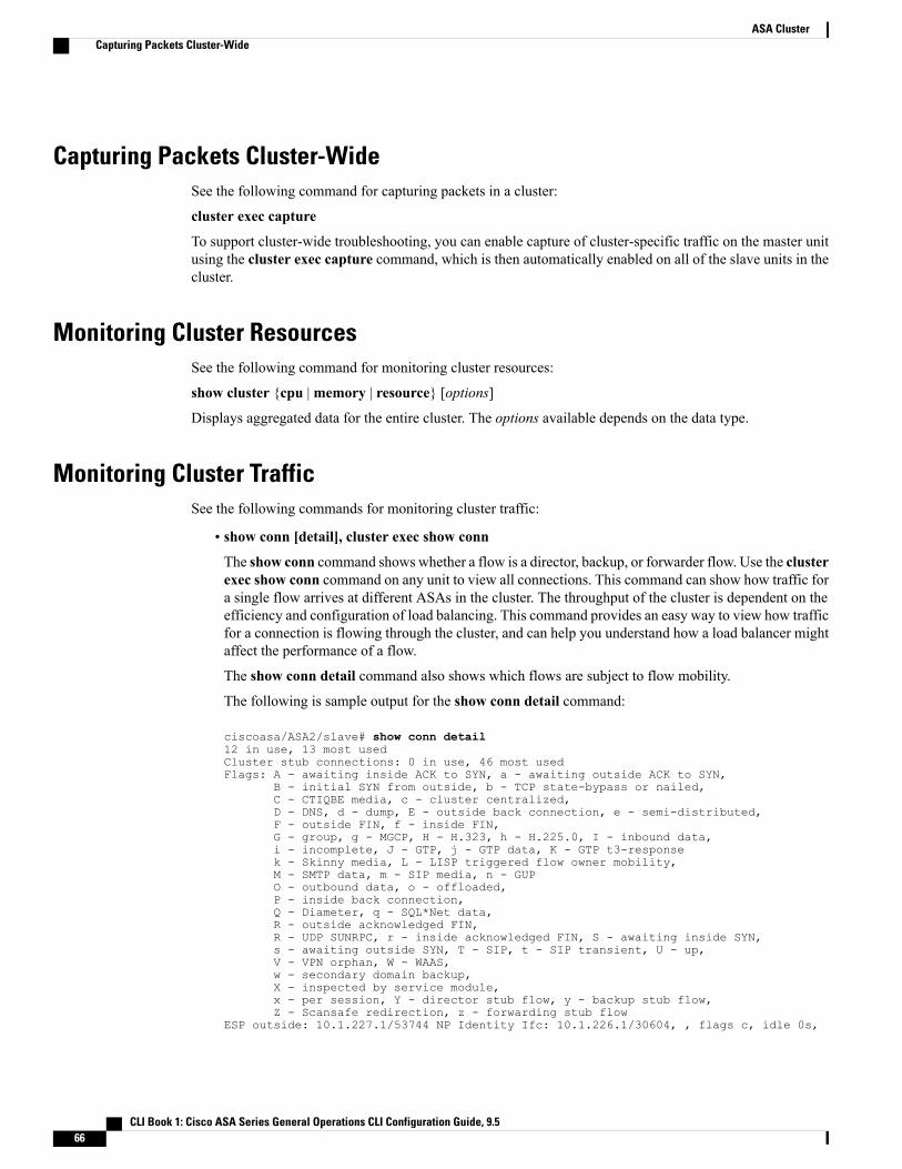
Capturing Packets Cluster-WideSee the following command for capturing packets in a cluster:
cluster exec capture
To support cluster-wide troubleshooting, you can enable capture of cluster-specific traffic on the master unitusing the cluster exec capture command, which is then automatically enabled on all of the slave units in thecluster.
Monitoring Cluster ResourcesSee the following command for monitoring cluster resources:
show cluster {cpu |memory | resource} [options]
Displays aggregated data for the entire cluster. The options available depends on the data type.
Monitoring Cluster TrafficSee the following commands for monitoring cluster traffic:
• show conn [detail], cluster exec show conn
The show conn command shows whether a flow is a director, backup, or forwarder flow. Use the clusterexec show conn command on any unit to view all connections. This command can show how traffic fora single flow arrives at different ASAs in the cluster. The throughput of the cluster is dependent on theefficiency and configuration of load balancing. This command provides an easy way to view how trafficfor a connection is flowing through the cluster, and can help you understand how a load balancer mightaffect the performance of a flow.
The show conn detail command also shows which flows are subject to flow mobility.
The following is sample output for the show conn detail command:
ciscoasa/ASA2/slave# show conn detail12 in use, 13 most usedCluster stub connections: 0 in use, 46 most usedFlags: A - awaiting inside ACK to SYN, a - awaiting outside ACK to SYN,
B - initial SYN from outside, b - TCP state-bypass or nailed,C - CTIQBE media, c - cluster centralized,D - DNS, d - dump, E - outside back connection, e - semi-distributed,F - outside FIN, f - inside FIN,G - group, g - MGCP, H - H.323, h - H.225.0, I - inbound data,i - incomplete, J - GTP, j - GTP data, K - GTP t3-responsek - Skinny media, L - LISP triggered flow owner mobility,M - SMTP data, m - SIP media, n - GUPO - outbound data, o - offloaded,P - inside back connection,Q - Diameter, q - SQL*Net data,R - outside acknowledged FIN,R - UDP SUNRPC, r - inside acknowledged FIN, S - awaiting inside SYN,s - awaiting outside SYN, T - SIP, t - SIP transient, U - up,V - VPN orphan, W - WAAS,w - secondary domain backup,X - inspected by service module,x - per session, Y - director stub flow, y - backup stub flow,Z - Scansafe redirection, z - forwarding stub flow
ESP outside: 10.1.227.1/53744 NP Identity Ifc: 10.1.226.1/30604, , flags c, idle 0s,
CLI Book 1: Cisco ASA Series General Operations CLI Configuration Guide, 9.566
ASA ClusterCapturing Packets Cluster-Wide

uptime1m21s, timeout 30s, bytes 7544, cluster sent/rcvd bytes 0/0, owners (0,255) Trafficreceivedat interface outside Locally received: 7544 (93 byte/s) Traffic received at interfaceNPIdentity Ifc Locally received: 0 (0 byte/s) UDP outside: 10.1.227.1/500 NP IdentityIfc:10.1.226.1/500, flags -c, idle 1m22s, uptime 1m22s, timeout 2m0s, bytes 1580, clustersent/rcvd bytes 0/0, cluster sent/rcvd total bytes 0/0, owners (0,255) Traffic receivedatinterface outside Locally received: 864 (10 byte/s) Traffic received at interface NPIdentityIfc Locally received: 716 (8 byte/s)
To troubleshoot the connection flow, first see connections on all units by entering the cluster exec showconn command on any unit. Look for flows that have the following flags: director (Y), backup (y), andforwarder (z). The following example shows an SSH connection from 172.18.124.187:22 to192.168.103.131:44727 on all three ASAs; ASA 1 has the z flag showing it is a forwarder for theconnection, ASA3 has the Y flag showing it is the director for the connection, and ASA2 has no specialflags showing it is the owner. In the outbound direction, the packets for this connection enter the insideinterface on ASA2 and exit the outside interface. In the inbound direction, the packets for this connectionenter the outside interface on ASA 1 and ASA3, are forwarded over the cluster control link to ASA2,and then exit the inside interface on ASA2.
ciscoasa/ASA1/master# cluster exec show connASA1(LOCAL):**********************************************************18 in use, 22 most usedCluster stub connections: 0 in use, 5 most usedTCP outside 172.18.124.187:22 inside 192.168.103.131:44727, idle 0:00:00, bytes37240828, flags z
ASA2:*****************************************************************12 in use, 13 most usedCluster stub connections: 0 in use, 46 most usedTCP outside 172.18.124.187:22 inside 192.168.103.131:44727, idle 0:00:00, bytes37240828, flags UIO
ASA3:*****************************************************************10 in use, 12 most usedCluster stub connections: 2 in use, 29 most usedTCP outside 172.18.124.187:22 inside 192.168.103.131:44727, idle 0:00:03, bytes 0,flags Y
• show cluster info [conn-distribution | packet-distribution | loadbalance | flow-mobility counters]
The show cluster info conn-distribution and show cluster info packet-distribution commands showtraffic distribution across all cluster units. These commands can help you to evaluate and adjust theexternal load balancer.
The show cluster info loadbalance command shows connection rebalance statistics.
The show cluster info flow-mobility counters command shows EID movement and flow ownermovement information. See the following output for show cluster info flow-mobility counters:
ciscoasa# show cluster info flow-mobility countersEID movement notification received : 4EID movement notification processed : 4Flow owner moving requested : 2
• show cluster {access-list | conn | traffic | user-identity | xlate} [options]
Displays aggregated data for the entire cluster. The options available depends on the data type.
CLI Book 1: Cisco ASA Series General Operations CLI Configuration Guide, 9.5 67
ASA ClusterMonitoring Cluster Traffic

See the following output for the show cluster access-list command:
ciscoasa# show cluster access-listhitcnt display order: cluster-wide aggregated result, unit-A, unit-B, unit-C, unit-Daccess-list cached ACL log flows: total 0, denied 0 (deny-flow-max 4096) alert-interval300access-list 101; 122 elements; name hash: 0xe7d586b5access-list 101 line 1 extended permit tcp 192.168.143.0 255.255.255.0 any eq www(hitcnt=0, 0, 0, 0, 0) 0x207a2b7daccess-list 101 line 2 extended permit tcp any 192.168.143.0 255.255.255.0 (hitcnt=0,0, 0, 0, 0) 0xfe4f4947access-list 101 line 3 extended permit tcp host 192.168.1.183 host 192.168.43.238(hitcnt=1, 0, 0, 0, 1) 0x7b521307access-list 101 line 4 extended permit tcp host 192.168.1.116 host 192.168.43.238(hitcnt=0, 0, 0, 0, 0) 0x5795c069access-list 101 line 5 extended permit tcp host 192.168.1.177 host 192.168.43.238(hitcnt=1, 0, 0, 1, 0) 0x51bde7eeaccess list 101 line 6 extended permit tcp host 192.168.1.177 host 192.168.43.13(hitcnt=0, 0, 0, 0, 0) 0x1e68697caccess-list 101 line 7 extended permit tcp host 192.168.1.177 host 192.168.43.132(hitcnt=2, 0, 0, 1, 1) 0xc1ce5c49access-list 101 line 8 extended permit tcp host 192.168.1.177 host 192.168.43.192(hitcnt=3, 0, 1, 1, 1) 0xb6f59512access-list 101 line 9 extended permit tcp host 192.168.1.177 host 192.168.43.44(hitcnt=0, 0, 0, 0, 0) 0xdc104200access-list 101 line 10 extended permit tcp host 192.168.1.112 host 192.168.43.44(hitcnt=429, 109, 107, 109, 104)0xce4f281daccess-list 101 line 11 extended permit tcp host 192.168.1.170 host 192.168.43.238(hitcnt=3, 1, 0, 0, 2) 0x4143a818access-list 101 line 12 extended permit tcp host 192.168.1.170 host 192.168.43.169(hitcnt=2, 0, 1, 0, 1) 0xb18dfea4access-list 101 line 13 extended permit tcp host 192.168.1.170 host 192.168.43.229(hitcnt=1, 1, 0, 0, 0) 0x21557d71access-list 101 line 14 extended permit tcp host 192.168.1.170 host 192.168.43.106(hitcnt=0, 0, 0, 0, 0) 0x7316e016access-list 101 line 15 extended permit tcp host 192.168.1.170 host 192.168.43.196(hitcnt=0, 0, 0, 0, 0) 0x013fd5b8access-list 101 line 16 extended permit tcp host 192.168.1.170 host 192.168.43.75(hitcnt=0, 0, 0, 0, 0) 0x2c7dba0d
To display the aggregated count of in-use connections for all units, enter:
ciscoasa# show cluster conn countUsage Summary In Cluster:*********************************************200 in use (cluster-wide aggregated)
cl2(LOCAL):***********************************************************100 in use, 100 most used
cl1:******************************************************************100 in use, 100 most used
• show asp cluster counter
This command is useful for datapath troubleshooting.
Monitoring Cluster RoutingSee the following commands for cluster routing:
• show route cluster
• debug route cluster
Shows cluster information for routing.
CLI Book 1: Cisco ASA Series General Operations CLI Configuration Guide, 9.568
ASA ClusterMonitoring Cluster Routing

• show lisp eid
Shows the ASA EID table showing EIDs and site IDs.
See the following output from the cluster exec show lisp eid command.
ciscoasa# cluster exec show lisp eidL1(LOCAL):************************************************************
LISP EID Site ID33.44.33.105 233.44.33.201 211.22.11.1 411.22.11.2 4
L2:*******************************************************************LISP EID Site ID33.44.33.105 233.44.33.201 211.22.11.1 411.22.11.2 4
• show asp table classify domain inspect-lisp
This command is useful for troubleshooting.
Configuring Logging for ClusteringSee the following command for configuring logging for clustering:
logging device-id
Each unit in the cluster generates syslog messages independently. You can use the logging device-id commandto generate syslog messages with identical or different device IDs to make messages appear to come from thesame or different units in the cluster.
Monitoring Cluster InterfacesSee the following commands for monitoring cluster interfaces:
• show cluster interface-mode
Shows the cluster interface mode.
• show port-channel
Includes information about whether a port-channel is spanned.
• show lacp cluster {system-mac | system-id}
Shows the cLACP system ID and priority.
• debug lacp cluster [all | ccp | misc | protocol]
Shows debug messages for cLACP.
• show interface
Shows the use of the site MAC address when in use:
ciscoasa# show interface port-channel1.3151Interface Port-channel1.3151 "inside", is up, line protocol is upHardware is EtherChannel/LACP, BW 1000 Mbps, DLY 10 usec
CLI Book 1: Cisco ASA Series General Operations CLI Configuration Guide, 9.5 69
ASA ClusterConfiguring Logging for Clustering

VLAN identifier 3151MAC address aaaa.1111.1234, MTU 1500Site Specific MAC address aaaa.1111.aaaaIP address 10.3.1.1, subnet mask 255.255.255.0Traffic Statistics for "inside":132269 packets input, 6483425 bytes1062 packets output, 110448 bytes98530 packets dropped
Debugging ClusteringSee the following commands for debugging clustering:
• debug cluster [ccp | datapath | fsm | general | hc | license | rpc | transport]
Shows debug messages for clustering.
• debug cluster flow-mobility
Shows events related to clustering flow mobility.
• debug lisp eid-notify-intercept
Shows events when the eid-notify message is intercepted.
• show cluster info trace
The show cluster info trace command shows the debug information for further troubleshooting.
See the following output for the show cluster info trace command:
ciscoasa# show cluster info traceFeb 02 14:19:47.456 [DBUG]Receive CCP message: CCP_MSG_LOAD_BALANCEFeb 02 14:19:47.456 [DBUG]Receive CCP message: CCP_MSG_LOAD_BALANCEFeb 02 14:19:47.456 [DBUG]Send CCP message to all: CCP_MSG_KEEPALIVE from 80-1 atMASTER
Examples for ASA ClusteringThese examples include all cluster-related ASA configuration for typical deployments.
Sample ASA and Switch ConfigurationThe following sample configurations connect the following interfaces between the ASA and the switch:
Switch InterfaceASA Interface
GigabitEthernet 1/0/15GigabitEthernet 0/2
GigabitEthernet 1/0/16GigabitEthernet 0/3
GigabitEthernet 1/0/17GigabitEthernet 0/4
GigabitEthernet 1/0/18GigabitEthernet 0/5
CLI Book 1: Cisco ASA Series General Operations CLI Configuration Guide, 9.570
ASA ClusterDebugging Clustering

ASA Configuration
Interface Mode on Each Unit
cluster interface-mode spanned force
ASA1 Master Bootstrap Configuration
interface GigabitEthernet0/0channel-group 1 mode onno shutdown!interface GigabitEthernet0/1channel-group 1 mode onno shutdown!interface Port-channel1description Clustering Interface!cluster group Moyalocal-unit Acluster-interface Port-channel1 ip 10.0.0.1 255.255.255.0priority 10key emphyri0enable noconfirm
ASA2 Slave Bootstrap Configuration
interface GigabitEthernet0/0channel-group 1 mode onno shutdown!interface GigabitEthernet0/1channel-group 1 mode onno shutdown!interface Port-channel1description Clustering Interface!cluster group Moyalocal-unit Bcluster-interface Port-channel1 ip 10.0.0.2 255.255.255.0priority 11key emphyri0enable as-slave
Master Interface Configuration
ip local pool mgmt-pool 10.53.195.231-10.53.195.232
interface GigabitEthernet0/2channel-group 10 mode activeno shutdown!interface GigabitEthernet0/3channel-group 10 mode activeno shutdown!
CLI Book 1: Cisco ASA Series General Operations CLI Configuration Guide, 9.5 71
ASA ClusterSample ASA and Switch Configuration

interface GigabitEthernet0/4channel-group 11 mode activeno shutdown!interface GigabitEthernet0/5channel-group 11 mode activeno shutdown!interface Management0/0management-onlynameif managementip address 10.53.195.230 cluster-pool mgmt-poolsecurity-level 100no shutdown!interface Port-channel10port-channel span-clustermac-address aaaa.bbbb.ccccnameif insidesecurity-level 100ip address 209.165.200.225 255.255.255.224!interface Port-channel11port-channel span-clustermac-address aaaa.dddd.ccccnameif outsidesecurity-level 0ip address 209.165.201.1 255.255.255.224
Cisco IOS Switch Configuration
interface GigabitEthernet1/0/15switchport access vlan 201switchport mode accessspanning-tree portfastchannel-group 10 mode active!interface GigabitEthernet1/0/16switchport access vlan 201switchport mode accessspanning-tree portfastchannel-group 10 mode active!interface GigabitEthernet1/0/17switchport access vlan 401switchport mode accessspanning-tree portfastchannel-group 11 mode active!interface GigabitEthernet1/0/18switchport access vlan 401switchport mode accessspanning-tree portfastchannel-group 11 mode active
interface Port-channel10switchport access vlan 201switchport mode access
interface Port-channel11switchport access vlan 401switchport mode access
CLI Book 1: Cisco ASA Series General Operations CLI Configuration Guide, 9.572
ASA ClusterSample ASA and Switch Configuration

Firewall on a Stick
Data traffic from different security domains are associated with different VLANs, for example, VLAN 10 forthe inside network and VLAN 20 for the outside network. Each ASA has a single physical port connected tothe external switch or router. Trunking is enabled so that all packets on the physical link are 802.1qencapsulated. The ASA is the firewall between VLAN 10 and VLAN 20.
When using Spanned EtherChannels, all data links are grouped into one EtherChannel on the switch side. Ifan ASA becomes unavailable, the switch will rebalance traffic between the remaining units.
Interface Mode on Each Unit
cluster interface-mode spanned force
ASA1 Master Bootstrap Configuration
interface tengigabitethernet 0/8
no shutdowndescription CCL
CLI Book 1: Cisco ASA Series General Operations CLI Configuration Guide, 9.5 73
ASA ClusterFirewall on a Stick

cluster group cluster1
local-unit asa1cluster-interface tengigabitethernet0/8 ip 192.168.1.1 255.255.255.0priority 1key chuntheunavoidableenable noconfirm
ASA2 Slave Bootstrap Configuration
interface tengigabitethernet 0/8
no shutdowndescription CCL
cluster group cluster1
local-unit asa2cluster-interface tengigabitethernet0/8 ip 192.168.1.2 255.255.255.0priority 2key chuntheunavoidableenable as-slave
ASA3 Slave Bootstrap Configuration
interface tengigabitethernet 0/8
no shutdowndescription CCL
cluster group cluster1
local-unit asa3cluster-interface tengigabitethernet0/8 ip 192.168.1.3 255.255.255.0priority 3key chuntheunavoidableenable as-slave
Master Interface Configuration
ip local pool mgmt 10.1.1.2-10.1.1.9ipv6 local pool mgmtipv6 2001:DB8::1002/64 8interface management 0/0
nameif managementip address 10.1.1.1 255.255.255.0 cluster-pool mgmtipv6 address 2001:DB8::1001/32 cluster-pool mgmtipv6security-level 100management-onlyno shutdown
interface tengigabitethernet 0/9
channel-group 2 mode activeno shutdowninterface port-channel 2port-channel span-clusterinterface port-channel 2.10vlan 10nameif insideip address 10.10.10.5 255.255.255.0ipv6 address 2001:DB8:1::5/64mac-address 000C.F142.4CDEinterface port-channel 2.20vlan 20
CLI Book 1: Cisco ASA Series General Operations CLI Configuration Guide, 9.574
ASA ClusterFirewall on a Stick

nameif outsideip address 209.165.201.1 255.255.255.224ipv6 address 2001:DB8:2::8/64mac-address 000C.F142.5CDE
Traffic Segregation
You may prefer physical separation of traffic between the inside and outside network.
As shown in the diagram above, there is one Spanned EtherChannel on the left side that connects to the insideswitch, and the other on the right side to outside switch. You can also create VLAN subinterfaces on eachEtherChannel if desired.
Interface Mode on Each Unit
cluster interface-mode spanned force
ASA1 Master Bootstrap Configuration
interface tengigabitethernet 0/6
channel-group 1 mode onno shutdown
interface tengigabitethernet 0/7
CLI Book 1: Cisco ASA Series General Operations CLI Configuration Guide, 9.5 75
ASA ClusterTraffic Segregation

channel-group 1 mode onno shutdowninterface port-channel 1description CCL
cluster group cluster1
local-unit asa1cluster-interface port-channel1 ip 192.168.1.1 255.255.255.0priority 1key chuntheunavoidableenable noconfirm
ASA2 Slave Bootstrap Configuration
interface tengigabitethernet 0/6
channel-group 1 mode onno shutdown
interface tengigabitethernet 0/7
channel-group 1 mode onno shutdowninterface port-channel 1description CCL
cluster group cluster1
local-unit asa2cluster-interface port-channel1 ip 192.168.1.2 255.255.255.0priority 2key chuntheunavoidableenable as-slave
ASA3 Slave Bootstrap Configuration
interface tengigabitethernet 0/6
channel-group 1 mode onno shutdown
interface tengigabitethernet 0/7
channel-group 1 mode onno shutdowninterface port-channel 1description CCL
cluster group cluster1
local-unit asa3cluster-interface port-channel1 ip 192.168.1.3 255.255.255.0priority 3key chuntheunavoidableenable as-slave
Master Interface Configuration
ip local pool mgmt 10.1.1.2-10.1.1.9ipv6 local pool mgmtipv6 2001:DB8::1002/64 8interface management 0/0
nameif management
CLI Book 1: Cisco ASA Series General Operations CLI Configuration Guide, 9.576
ASA ClusterTraffic Segregation

ip address 10.1.1.1 255.255.255.0 cluster-pool mgmtipv6 address 2001:DB8::1001/32 cluster-pool mgmtipv6security-level 100management-onlyno shutdown
interface tengigabitethernet 0/8
channel-group 2 mode activeno shutdowninterface port-channel 2port-channel span-clusternameif insideip address 10.10.10.5 255.255.255.0ipv6 address 2001:DB8:1::5/64mac-address 000C.F142.4CDE
interface tengigabitethernet 0/9
channel-group 3 mode activeno shutdowninterface port-channel 3port-channel span-clusternameif outsideip address 209.165.201.1 255.255.255.224ipv6 address 2001:DB8:2::8/64mac-address 000C.F142.5CDE
Spanned EtherChannel with Backup Links (Traditional 8 Active/8 Standby)The maximum number of active ports in a traditional EtherChannel is limited to 8 from the switch side. Ifyou have an 8-ASA cluster, and you allocate 2 ports per unit to the EtherChannel, for a total of 16 ports total,then 8 of them have to be in standby mode. The ASA uses LACP to negotiate which links should be activeor standby. If you enable multi-switch EtherChannel using VSS or vPC, you can achieve inter-switchredundancy. On the ASA, all physical ports are ordered first by the slot number then by the port number. Inthe following figure, the lower ordered port is the “master” port (for example, GigabitEthernet 0/0), and theother one is the “slave” port (for example, GigabitEthernet 0/1). Youmust guarantee symmetry in the hardwareconnection: all master links must terminate on one switch, and all slave links must terminate on another switchif VSS/vPC is used. The following diagram shows what happens when the total number of links grows asmore units join the cluster:
CLI Book 1: Cisco ASA Series General Operations CLI Configuration Guide, 9.5 77
ASA ClusterSpanned EtherChannel with Backup Links (Traditional 8 Active/8 Standby)

The principle is to first maximize the number of active ports in the channel, and secondly keep the numberof active master ports and the number of active slave ports in balance. Note that when a 5th unit joins thecluster, traffic is not balanced evenly between all units.
Link or device failure is handled with the same principle. You may end up with a less-than-perfect loadbalancing situation. The following figure shows a 4-unit cluster with a single link failure on one of the units.
CLI Book 1: Cisco ASA Series General Operations CLI Configuration Guide, 9.578
ASA ClusterSpanned EtherChannel with Backup Links (Traditional 8 Active/8 Standby)

There could be multiple EtherChannels configured in the network. The following diagram shows anEtherChannel on the inside and one on the outside. An ASA is removed from the cluster if both master andslave links in one EtherChannel fail. This prevents the ASA from receiving traffic from the outside networkwhen it has already lost connectivity to the inside network.
CLI Book 1: Cisco ASA Series General Operations CLI Configuration Guide, 9.5 79
ASA ClusterSpanned EtherChannel with Backup Links (Traditional 8 Active/8 Standby)

Interface Mode on Each Unit
cluster interface-mode spanned force
ASA1 Master Bootstrap Configuration
interface tengigabitethernet 0/6
channel-group 1 mode onno shutdown
interface tengigabitethernet 0/7
channel-group 1 mode onno shutdown
interface tengigabitethernet 0/8
channel-group 1 mode onno shutdown
interface tengigabitethernet 0/9
channel-group 1 mode onno shutdown
CLI Book 1: Cisco ASA Series General Operations CLI Configuration Guide, 9.580
ASA ClusterSpanned EtherChannel with Backup Links (Traditional 8 Active/8 Standby)

interface port-channel 1description CCL
cluster group cluster1
local-unit asa1cluster-interface port-channel1 ip 192.168.1.1 255.255.255.0priority 1key chuntheunavoidableenable noconfirm
ASA2 Slave Bootstrap Configuration
interface tengigabitethernet 0/6
channel-group 1 mode onno shutdown
interface tengigabitethernet 0/7
channel-group 1 mode onno shutdown
interface tengigabitethernet 0/8
channel-group 1 mode onno shutdown
interface tengigabitethernet 0/9
channel-group 1 mode onno shutdowninterface port-channel 1description CCL
cluster group cluster1
local-unit asa2cluster-interface port-channel1 ip 192.168.1.2 255.255.255.0priority 2key chuntheunavoidableenable as-slave
ASA3 Slave Bootstrap Configuration
interface tengigabitethernet 0/6
channel-group 1 mode onno shutdown
interface tengigabitethernet 0/7
channel-group 1 mode onno shutdown
interface tengigabitethernet 0/8
channel-group 1 mode onno shutdown
interface tengigabitethernet 0/9
channel-group 1 mode onno shutdowninterface port-channel 1description CCL
CLI Book 1: Cisco ASA Series General Operations CLI Configuration Guide, 9.5 81
ASA ClusterSpanned EtherChannel with Backup Links (Traditional 8 Active/8 Standby)

cluster group cluster1
local-unit asa3cluster-interface port-channel1 ip 192.168.1.3 255.255.255.0priority 3key chuntheunavoidableenable as-slave
ASA4 Slave Bootstrap Configuration
interface tengigabitethernet 0/6
channel-group 1 mode onno shutdown
interface tengigabitethernet 0/7
channel-group 1 mode onno shutdown
interface tengigabitethernet 0/8
channel-group 1 mode onno shutdown
interface tengigabitethernet 0/9
channel-group 1 mode onno shutdowninterface port-channel 1description CCL
cluster group cluster1
local-unit asa4cluster-interface port-channel1 ip 192.168.1.4 255.255.255.0priority 4key chuntheunavoidableenable as-slave
Master Interface Configuration
ip local pool mgmt 10.1.1.2-10.1.1.9interface management 0/0
channel-group 2 mode activeno shutdown
interface management 0/1
channel-group 2 mode activeno shutdowninterface port-channel 2nameif managementip address 10.1.1.1 255.255.255.0 cluster-pool mgmtsecurity-level 100management-only
interface tengigabitethernet 1/6
channel-group 3 mode active vss-id 1no shutdown
interface tengigabitethernet 1/7
channel-group 3 mode active vss-id 2no shutdown
CLI Book 1: Cisco ASA Series General Operations CLI Configuration Guide, 9.582
ASA ClusterSpanned EtherChannel with Backup Links (Traditional 8 Active/8 Standby)

interface port-channel 3port-channel span-cluster vss-load-balancenameif insideip address 10.10.10.5 255.255.255.0mac-address 000C.F142.4CDE
interface tengigabitethernet 1/8
channel-group 4 mode active vss-id 1no shutdown
interface tengigabitethernet 1/9
channel-group 4 mode active vss-id 2no shutdowninterface port-channel 4port-channel span-cluster vss-load-balancenameif outsideip address 209.165.201.1 255.255.255.224mac-address 000C.F142.5CDE
OTV Configuration for Routed Mode Inter-Site ClusteringThe success of inter-site clustering for routed mode with Spanned EtherChannels depends on the properconfiguration and monitoring of OTV. OTV plays a major role by forwarding the packets across the DCI.OTV forwards unicast packets across the DCI only when it learns the MAC address in its forwarding table.If the MAC address is not learned in the OTV forwarding table, it will drop the unicast packets.
Sample OTV Configuration
//Sample OTV config://3151 – Inside VLAN, 3152 – Outside VLAN, 202 – CCL VLAN//aaaa.1111.1234 – ASA inside interface global vMAC//0050.56A8.3D22 – Server MAC
feature ospffeature otv
mac access-list ALL_MACs10 permit any any
mac access-list HSRP_VMAC10 permit aaaa.1111.1234 0000.0000.0000 any20 permit aaaa.2222.1234 0000.0000.0000 any30 permit any aaaa.1111.1234 0000.0000.000040 permit any aaaa.2222.1234 0000.0000.0000
vlan access-map Local 10match mac address HSRP_VMACaction drop
vlan access-map Local 20match mac address ALL_MACsaction forward
vlan filter Local vlan-list 3151-3152
no ip igmp snooping optimise-multicast-floodvlan 1,202,1111,2222,3151-3152
otv site-vlan 2222mac-list GMAC_DENY seq 10 deny aaaa.aaaa.aaaa ffff.ffff.ffffmac-list GMAC_DENY seq 20 deny aaaa.bbbb.bbbb ffff.ffff.ffffmac-list GMAC_DENY seq 30 permit 0000.0000.0000 0000.0000.0000route-map stop-GMAC permit 10match mac-list GMAC_DENY
CLI Book 1: Cisco ASA Series General Operations CLI Configuration Guide, 9.5 83
ASA ClusterOTV Configuration for Routed Mode Inter-Site Clustering

interface Overlay1otv join-interface Ethernet8/1otv control-group 239.1.1.1otv data-group 232.1.1.0/28otv extend-vlan 202, 3151otv arp-nd timeout 60no shutdown
interface Ethernet8/1description uplink_to_OTV_cloudmtu 9198ip address 10.4.0.18/24ip igmp version 3no shutdown
interface Ethernet8/2
interface Ethernet8/3description back_to_default_vdc_e6/39switchportswitchport mode trunkswitchport trunk allowed vlan 202,2222,3151-3152
mac packet-classifyno shutdown
otv-isis defaultvpn Overlay1redistribute filter route-map stop-GMAC
otv site-identifier 0x2
otv flood mac 0050.56A8.3D22 vlan 3151
OTV Filter Modifications Required Because of Site Failure
If a site goes down, the filters need to be removed from OTV because you do not want to block the globalMAC address anymore. There are some additional configurations required.
You need to add a static entry for the ASA global MAC address on the OTV switch in the site that is functional.This entry will let the OTV at the other end add these entries on the overlay interface. This step is requiredbecause if the server and client already have the ARP entry for the ASA, which is the case for existingconnections, then they will not send the ARP again. Therefore, OTV will not get a chance to learn the ASAglobal MAC address in its forwarding table. Because OTV does not have the global MAC address in itsforwarding table, and per OTV design it will not flood unicast packets over the overlay interface, then it willdrop the unicast packets to the global MAC address from the server, and the existing connections will break.
//OTV filter configs when one of the sites is down
mac-list GMAC_A seq 10 permit 0000.0000.0000 0000.0000.0000route-map a-GMAC permit 10match mac-list GMAC_A
otv-isis defaultvpn Overlay1redistribute filter route-map a-GMAC
no vlan filter Local vlan-list 3151
mac address-table static aaaa.1111.1234 vlan 3151 interface Ethernet8/3//Static entry required only in the OTV in the functioning Site
When the other site is restored, you need to add the filters back again and remove this static entry on the OTV.It is very important to clear the dynamic MAC address table on both the OTVs to clear the overlay entry forthe global MAC address.
CLI Book 1: Cisco ASA Series General Operations CLI Configuration Guide, 9.584
ASA ClusterOTV Configuration for Routed Mode Inter-Site Clustering

MAC Address Table Clearing
When a site goes down, and a static entry for the global MAC address is added to OTV, you need to let theother OTV learn the global MAC address on the overlay interface. After the other site comes up, these entriesshould be cleared. Make sure to clear the mac address table to make sure OTV does not have these entries inits forwarding table.
cluster-N7k6-OTV# show mac address-tableLegend:* - primary entry, G - Gateway MAC, (R) - Routed MAC, O - Overlay MACage - seconds since last seen,+ - primary entry using vPC Peer-Link,(T) - True, (F) - FalseVLAN MAC Address Type age Secure NTFY Ports/SWID.SSID.LID---------+-----------------+--------+---------+------+----+------------------G - d867.d900.2e42 static - F F sup-eth1(R)O 202 885a.92f6.44a5 dynamic - F F Overlay1* 202 885a.92f6.4b8f dynamic 5 F F Eth8/3O 3151 0050.5660.9412 dynamic - F F Overlay1* 3151 aaaa.1111.1234 dynamic 50 F F Eth8/3
OTV ARP Cache Monitoring
OTV maintains an ARP cache to proxy ARP for IP addresses that it learned across the OTV interface.
cluster-N7k6-OTV# show otv arp-nd-cacheOTV ARP/ND L3->L2 Address Mapping Cache
Overlay Interface Overlay1VLAN MAC Address Layer-3 Address Age Expires In3151 0050.5660.9412 10.0.0.2 1w0d 00:00:31cluster-N7k6-OTV#
Examples for Inter-Site ClusteringThe following examples show supported cluster deployments.
Individual Interface Routed Mode North-South Inter-Site ExampleThe following example shows 2 ASA cluster members at each of 2 data centers placed between inside andoutside routers (North-South insertion). The cluster members are connected by the cluster control link overthe DCI. The inside and outside routers at each data center use OSPF and PBR or ECMP to load balance thetraffic between cluster members. By assigning a higher cost route across the DCI, traffic stays within eachdata center unless all ASA cluster members at a given site go down. In the event of a failure of all clustermembers at one site, traffic goes from each router over the DCI to the ASA cluster members at the other site.
CLI Book 1: Cisco ASA Series General Operations CLI Configuration Guide, 9.5 85
ASA ClusterExamples for Inter-Site Clustering

Spanned EtherChannel Routed Mode Example with Site-Specific MAC AddressesThe following example shows 2 cluster members at each of 2 data centers placed between the gateway routerand an inside network at each site (East-West insertion). The cluster members are connected by the clustercontrol link over the DCI. The cluster members at each site connect to the local switches using spannedEtherChannels for both the inside and outside networks. Each EtherChannel is spanned across all chassis inthe cluster.
The data VLANs are extended between the sites using Overlay Transport Virtualization (OTV) (or somethingsimilar). You must add filters blocking the global MAC address to prevent traffic from traversing the DCI tothe other site when the traffic is destined for the cluster. If the cluster units at one site become unreachable,you must remove the filters so traffic can be sent to the other site’s cluster units. You should use VACLs tofilter the global MAC address.Be sure to disable ARP inspection. See OTV Configuration for Routed ModeInter-Site Clustering, on page 83 for more information.
The cluster acts as the gateway for the inside networks. The global virtual MAC, which is shared across allcluster units, is used only to receive packets. Outgoing packets use a site-specific MAC address from eachDC cluster. This feature prevents the switches from learning the same global MAC address from both siteson two different ports, which causes MAC flapping; instead, they only learn the site MAC address.
In this scenario:
• All egress packets sent from the cluster use the site MAC address and are localized at the data center.
• All ingress packets to the cluster are sent using the global MAC address, so they can be received by anyof the units at both sites; filters at the OTV localize the traffic within the data center.
CLI Book 1: Cisco ASA Series General Operations CLI Configuration Guide, 9.586
ASA ClusterExamples for Inter-Site Clustering

For a sample OTV configuration and best practices, see OTV Configuration for Routed Mode Inter-SiteClustering, on page 83.
Spanned EtherChannel Transparent Mode North-South Inter-Site ExampleThe following example shows 2 cluster members at each of 2 data centers placed between inside and outsiderouters (North-South insertion). The cluster members are connected by the cluster control link over the DCI.The cluster members at each site connect to the local switches using spanned EtherChannels for the insideand outside. Each EtherChannel is spanned across all chassis in the cluster.
The inside and outside routers at each data center use OSPF, which is passed through the transparent ASAs.Unlike MACs, router IPs are unique on all routers. By assigning a higher cost route across the DCI, trafficstays within each data center unless all cluster members at a given site go down. The lower cost route throughthe ASAs must traverse the same bridge group at each site for the cluster to maintain asymmetric connections.In the event of a failure of all cluster members at one site, traffic goes from each router over the DCI to thecluster members at the other site.
CLI Book 1: Cisco ASA Series General Operations CLI Configuration Guide, 9.5 87
ASA ClusterExamples for Inter-Site Clustering

The implementation of the switches at each site can include:
• Inter-site VSS/vPC—In this scenario, you install one switch at Data Center 1, and the other at DataCenter 2. One option is for the cluster units at each Data Center to only connect to the local switch, whilethe VSS/vPC traffic goes across the DCI. In this case, connections are for the most part kept local toeach datacenter. You can optionally connect each unit to both switches across the DCI if the DCI canhandle the extra traffic. In this case, traffic is distributed across the data centers, so it is essential for theDCI to be very robust.
• Local VSS/vPC at each site—For better switch redundancy, you can install 2 separate VSS/vPC pairsat each site. In this case, although the cluster units still have a spanned EtherChannel with Data Center1 chassis connected only to both local switches, and Data Center 2 chassis connected to those localswitches, the spanned EtherChannel is essentially “split.” Each local VSS/vPC sees the spannedEtherChannel as a site-local EtherChannel.
Spanned EtherChannel Transparent Mode East-West Inter-Site ExampleThe following example shows 2 cluster members at each of 2 data centers placed between the gateway routerand two inside networks at each site, the App network and the DB network (East-West insertion). The clustermembers are connected by the cluster control link over the DCI. The cluster members at each site connect tothe local switches using spanned EtherChannels for both the App and DB networks on the inside and outside.Each EtherChannel is spanned across all chassis in the cluster.
The gateway router at each site uses an FHRP such as HSRP to provide the same destination virtual MACand IP addresses at each site. A good practice to avoid unintended MAC address flapping is to statically addthe gateway routers real MAC addresses to the ASA MAC address table using themac-address-table static
CLI Book 1: Cisco ASA Series General Operations CLI Configuration Guide, 9.588
ASA ClusterExamples for Inter-Site Clustering

outside_interface mac_address command. Without these entries, if the gateway at site 1 communicates withthe gateway at site 2, that traffic might pass through the ASA and attempt to reach site 2 from the insideinterface and cause problems. The data VLANs are extended between the sites using Overlay TransportVirtualization (OTV) (or something similar). You must add filters to prevent traffic from traversing the DCIto the other site when the traffic is destined for the gateway router. If the gateway router at one site becomesunreachable, you must remove the filters so traffic can be sent to the other site’s gateway router.
See Spanned EtherChannel Transparent Mode North-South Inter-Site Example, on page 87 for informationabout vPC/VSS options.
CLI Book 1: Cisco ASA Series General Operations CLI Configuration Guide, 9.5 89
ASA ClusterExamples for Inter-Site Clustering

History for ASA ClusteringFeature InformationPlatform
ReleasesFeature Name
ASA Clustering lets you group multiple ASAs together as a single logical device. A clusterprovides all the convenience of a single device (management, integration into a network) whileachieving the increased throughput and redundancy of multiple devices. ASA clustering issupported for the ASA 5580 and the ASA 5585-X; all units in a cluster must be the samemodelwith the same hardware specifications. See the configuration guide for a list of unsupportedfeatures when clustering is enabled.
We introduced or modified the following commands: channel-group, clacp system-mac,clear cluster info, clear configure cluster, cluster exec, cluster group, clusterinterface-mode, cluster-interface, conn-rebalance, console-replicate, cluster master unit,cluster remove unit, debug cluster, debug lacp cluster, enable (cluster group), health-check,ip address, ipv6 address, key (cluster group), local-unit, mac-address (interface),mac-address pool,mtu cluster, port-channel span-cluster, priority (cluster group), promptcluster-unit, show asp cluster counter, show asp table cluster chash-table, show cluster,show cluster info, show cluster user-identity, show lacp cluster, and show running-configcluster.
9.0(1)ASA Clustering for theASA 5580 and 5585-X
The ASA 5512-X, ASA 5515-X, ASA 5525-X, ASA 5545-X, and ASA 5555-X now support2-unit clusters. Clustering for 2 units is enabled by default in the base license; for the ASA5512-X, you need the Security Plus license.
We did not modify any commands.
9.1(4)ASA 5500-X support forclustering
If you configure the cluster control link as an EtherChannel (recommended), and it is connectedto a VSS or vPC pair, you can now increase stability with health check monitoring. For someswitches, such as the Cisco Nexus 5000, when one unit in the VSS/vPC is shutting down orbooting up, EtherChannel member interfaces connected to that switch may appear to be Up tothe ASA, but they are not passing traffic on the switch side. The ASA can be erroneouslyremoved from the cluster if you set the ASA holdtime timeout to a low value (such as .8seconds), and the ASA sends keepalive messages on one of these EtherChannel interfaces.When you enable the VSS/vPC health check feature, the ASA floods the keepalive messageson all EtherChannel interfaces in the cluster control link to ensure that at least one of theswitches can receive them.
We modified the following command: health-check [vss-enabled].
9.1(4)Improved VSS and vPCsupport for health checkmonitoring
You can now place cluster members at different geographical locations when using IndividualInterface mode.
We did not modify any commands.
9.1(4)Support for clustermembers at differentgeographical locations(inter-site); IndividualInterface mode only
CLI Book 1: Cisco ASA Series General Operations CLI Configuration Guide, 9.590
ASA ClusterHistory for ASA Clustering

Feature InformationPlatformReleases
Feature Name
You can now place cluster members at different geographical locations when using SpannedEtherChannel mode in transparent firewall mode. Inter-site clustering with spannedEtherChannels in routed firewall mode is not supported.
We did not modify any commands.
9.2(1)Support for clustermembers at differentgeographical locations(inter-site) fortransparent mode
Some switches do not support dynamic port priority with LACP (active and standby links).You can now disable dynamic port priority to provide better compatibility with spannedEtherChannels. You should also follow these guidelines:
• Network elements on the cluster control link path should not verify the L4 checksum.Redirected traffic over the cluster control link does not have a correct L4 checksum.Switches that verify the L4 checksum could cause traffic to be dropped.
• Port-channel bundling downtime should not exceed the configured keepalive interval.
We introduced the following command: clacp static-port-priority.
9.2(1)Static LACP portpriority support forclustering
ASA EtherChannels now support up to 16 active links. With spanned EtherChannels, thatfunctionality is extended to support up to 32 active links across the cluster when used withtwo switches in a vPC and when you disable dynamic port priority. The switches must supportEtherChannels with 16 active links, for example, the Cisco Nexus 7000 with F2-Series 10Gigabit Ethernet Module.
For switches in a VSS or vPC that support 8 active links, you can now configure 16 activelinks in the spanned EtherChannel (8 connected to each switch). Previously, the spannedEtherChannel only supported 8 active links and 8 standby links, even for use with a VSS/vPC.
If you want to use more than 8 active links in a spanned EtherChannel, you cannotalso have standby links; the support for 9 to 32 active links requires you to disablecLACP dynamic port priority that allows the use of standby links.
Note
We introduced the following command: clacp static-port-priority.
9.2(1)Support for 32 activelinks in a spannedEtherChannel
The ASA 5585-X now supports 16-unit clusters.
We did not modify any commands.
9.2(1)Support for 16 clustermembers for the ASA5585-X
We added support for BGP with ASA clustering.
We introduced the following command: bgp router-id clusterpool.
9.3(1)BGP support for ASAclustering
You can now deploy a cluster in transparent mode between inside networks and the gatewayrouter at each site (AKA East-West insertion), and extend the inside VLANs between sites.We recommend using Overlay Transport Virtualization (OTV), but you can use any methodthat ensures that the overlapping MAC Addresses and IP addresses of the gateway router donot leak between sites. Use a First Hop Redundancy Protocol (FHRP) such as HSRP to providethe same virtual MAC and IP addresses to the gateway routers.
9.3(2)Inter-site deployment intransparent mode withthe ASA clusterfirewalling betweeninside networks
CLI Book 1: Cisco ASA Series General Operations CLI Configuration Guide, 9.5 91
ASA ClusterHistory for ASA Clustering

Feature InformationPlatformReleases
Feature Name
You can now enable or disable health monitoring per interface. Health monitoring is enabledby default on all port-channel, redundant, and single physical interfaces. Health monitoring isnot performed on VLAN subinterfaces or virtual interfaces such as VNIs or BVIs. You cannotconfigure monitoring for the cluster control link; it is always monitored. You might want todisable health monitoring of non-essential interfaces, for example, the management interface.
We introduced the following command: health-check monitor-interface.
9.4(1)Enable and disable ASAcluster healthmonitoringper interface
You can now configure DHCP relay on the ASA cluster. Client DHCP requests areload-balanced to the cluster members using a hash of the client MAC address. DHCP clientand server functions are still not supported.
We did not modify any commands.
9.4(1)ASA clustering supportfor DHCP relay
You can now configure SIP inspection on the ASA cluster. A control flow can be created onany unit (due to load balancing), but its child data flows must reside on the same unit. TLSProxy configuration is not supported.
We introduced the following command: show cluster service-policy.
9.4(1)SIP inspection supportin ASA clustering
You can now use inter-site clustering for Spanned EtherChannels in routed mode. To avoidMAC address flapping, configure a site ID for each cluster member so that a site-specificMACaddress for each interface can be shared among a site’s units.We introduced or modified the following commands: site-id, mac-address site-id, showcluster info, show interface
9.5(1)Site-specific MACaddresses for inter-siteclustering support forSpanned EtherChannelin Routed firewall mode
You can now customize the auto-rejoin behavior when an interface or the cluster control linkfails.
We introduced the following command: health-check auto-rejoin
9.5(1)ASA clustercustomization of theauto-rejoin behaviorwhen an interface or thecluster control link fails
The ASA cluster now supports GTPv1 and GTPv2 inspection.
We did not modify any commands.
9.5(1)The ASA clustersupports GTPv1 andGTPv2
By default when using clustering, the ASAmonitors the health of an installed hardware modulesuch as the ASA FirePOWERmodule. If you do not want a hardware module failure to triggerfailover, you can disable module monitoring.
We modified the following command: health-check monitor-interface service-module
9.5(1)Disable healthmonitoring of ahardware module inASA clustering
This feature helps eliminate the “unnecessary work” related to short-lived flows by delayingthe director/backup flow creation.
We introduced the following command: cluster replication delay
9.5(1)Cluster replication delayfor TCP connections
The ASA 5516-X now supports 2-unit clusters. Clustering for 2 units is enabled by default inthe base license.
We did not modify any commands.
9.5(2)ASA 5516-X support forclustering
CLI Book 1: Cisco ASA Series General Operations CLI Configuration Guide, 9.592
ASA ClusterHistory for ASA Clustering

Feature InformationPlatformReleases
Feature Name
Cisco Locator/ID Separation Protocol (LISP) architecture separates the device identity fromits location into two different numbering spaces, making server migration transparent to clients.The ASA can inspect LISP traffic for location changes and then use this information forseamless clustering operation; the ASA cluster members inspect LISP traffic passing betweenthe first hop router and the egress tunnel router (ETR) or ingress tunnel router (ITR), and thenchange the flow owner to be at the new site.
We introduced or modified the following commands: allowed-eid, clear cluster infoflow-mobility counters, clear lisp eid, cluster flow-mobility lisp, debug clusterflow-mobility, debug lisp eid-notify-intercept, flow-mobility lisp, inspect lisp, policy-maptype inspect lisp, site-id, show asp table classify domain inspect-lisp, show cluster infoflow-mobility counters, show conn, show lisp eid, show service-policy, validate-key
9.5(2)LISP Inspection forInter-Site FlowMobility
For carrier-grade or large-scale PAT, you can allocate a block of ports for each host, ratherthan have NAT allocate one port translation at a time (see RFC 6888). This feature is nowsupported in failover and ASA cluster deployments.
We modified the following command: show local-host
9.5(2)Carrier Grade NATenhancements nowsupported in failover andASA clustering
By default, all levels of clustering events are included in the trace buffer, including many lowlevel events. To limit the trace to higher level events, you can set the minimum trace level forthe cluster.
We introduced the following command: trace-level
9.5(2)Configurable level forclustering trace entries
CLI Book 1: Cisco ASA Series General Operations CLI Configuration Guide, 9.5 93
ASA ClusterHistory for ASA Clustering

CLI Book 1: Cisco ASA Series General Operations CLI Configuration Guide, 9.594
ASA ClusterHistory for ASA Clustering