asabe pe reviewmachine design
TRANSCRIPT
7/27/2019 ASABE PE REVIEW�MACHINE DESIGN
http://slidepdf.com/reader/full/asabe-pe-reviewmachine-design 1/80
ASABE PE REVIEW
MACHINE DESIGNLarry F. Stikeleather, P.E.
Note: some problems patterned after problems in
―Mechanical Engineering Exam File‖ by Richard K.
Pefley, P.E., Engineering Press, Inc. 1986
Reference for fatigue and shaft sizing is mainly based
upon ―Machine Design, Theory and Practice‖ by
Deutschman, Michels, and Wilson (an old but great book)
Biological & Agric. Engr, NCSU
7/27/2019 ASABE PE REVIEW�MACHINE DESIGN
http://slidepdf.com/reader/full/asabe-pe-reviewmachine-design 2/80
Other references recommended
Any basic text on Machine Design should serve you well in
preparation for the PE exam. For example:
Design of Machine Elements, M.F. Spotts
Machine Elements in Mechanical Design, Robert L. MottMachine Design an integrated approach, Robert L. Norton
Mechanical Engineering Design, Shigley/Mischke/Budynas
7/27/2019 ASABE PE REVIEW�MACHINE DESIGN
http://slidepdf.com/reader/full/asabe-pe-reviewmachine-design 3/80
Machine design — what is it?
Subset of Mechanical design…which isSubset of Engineering design…which is
Subset of Design….which is
Subset of the topic of Problem Solving
What is a machine? …a combination of resistant bodies arranged so that by their
means the mechanical forces of nature can be
compelled to do work accompanied by certain
determinate motions.

7/27/2019 ASABE PE REVIEW�MACHINE DESIGN
http://slidepdf.com/reader/full/asabe-pe-reviewmachine-design 4/80
Big picture
Mechanics
Statics Dynamics
kinematics Kinetics
motionMotion and forces
Change
with timeTime not a
factor
7/27/2019 ASABE PE REVIEW�MACHINE DESIGN
http://slidepdf.com/reader/full/asabe-pe-reviewmachine-design 5/80
The Design Process
•Recognize need/define problem
•Create a solution/design
•Prepare model/prototype/solution
•
Test and evaluate•Communicate design
7/27/2019 ASABE PE REVIEW�MACHINE DESIGN
http://slidepdf.com/reader/full/asabe-pe-reviewmachine-design 6/80
Important to review the
fundamentals of…. •Statics
•Dynamics
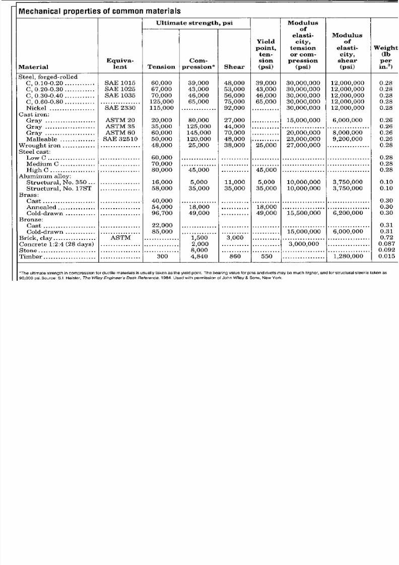
•Materials/material properties
•elasticity
•homogeneity
•isotropy
•mass and area parameters

7/27/2019 ASABE PE REVIEW�MACHINE DESIGN
http://slidepdf.com/reader/full/asabe-pe-reviewmachine-design 7/80
Lets begin our brief review
7/27/2019 ASABE PE REVIEW�MACHINE DESIGN
http://slidepdf.com/reader/full/asabe-pe-reviewmachine-design 8/80
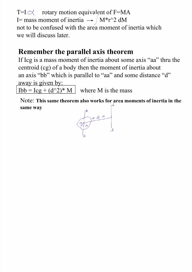
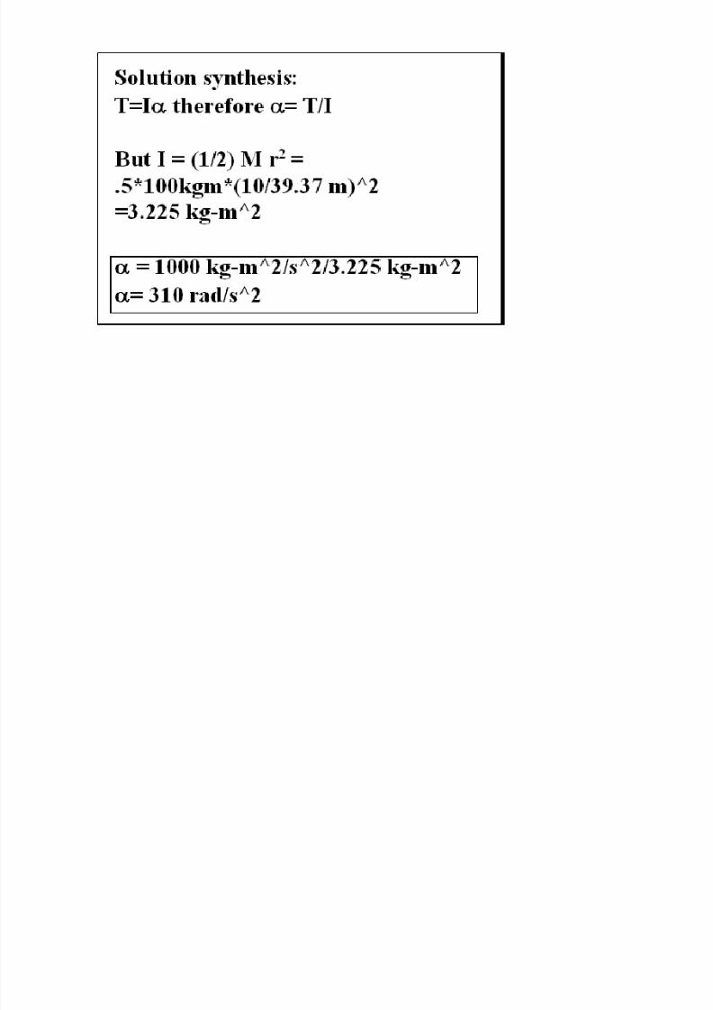
T=I rotary motion equivalent of F=MA
I= mass moment of inertia M*r^2 dM
not to be confused with the area moment of inertia which
we will discuss later.
Remember the parallel axis theorem
If Icg is a mass moment of inertia about some axis ―aa‖ thru the
centroid (cg) of a body then the moment of inertia aboutan axis ―bb‖ which is parallel to ―aa‖ and some distance ―d‖
away is given by:
Ibb = Icg + (d^2)* M where M is the mass
Note: This same theorem also works for area moments of inertia in thesame way
7/27/2019 ASABE PE REVIEW�MACHINE DESIGN
http://slidepdf.com/reader/full/asabe-pe-reviewmachine-design 9/80
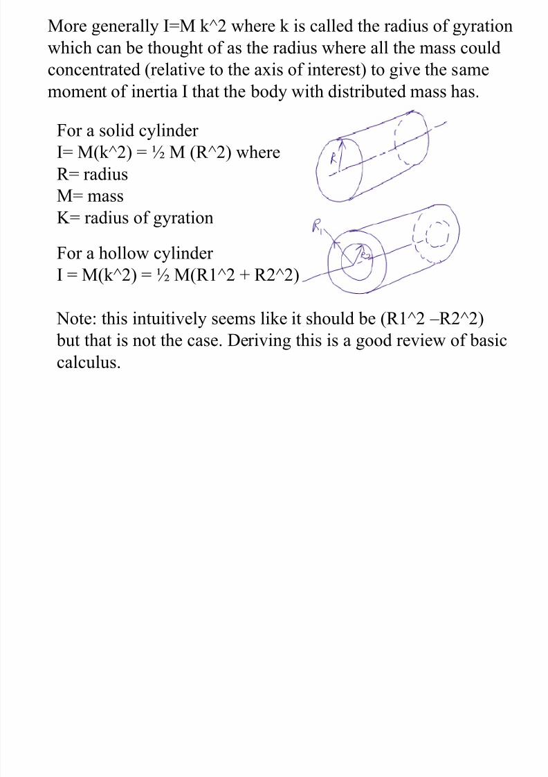
More generally I=M k^2 where k is called the radius of gyration
which can be thought of as the radius where all the mass could
concentrated (relative to the axis of interest) to give the same
moment of inertia I that the body with distributed mass has.
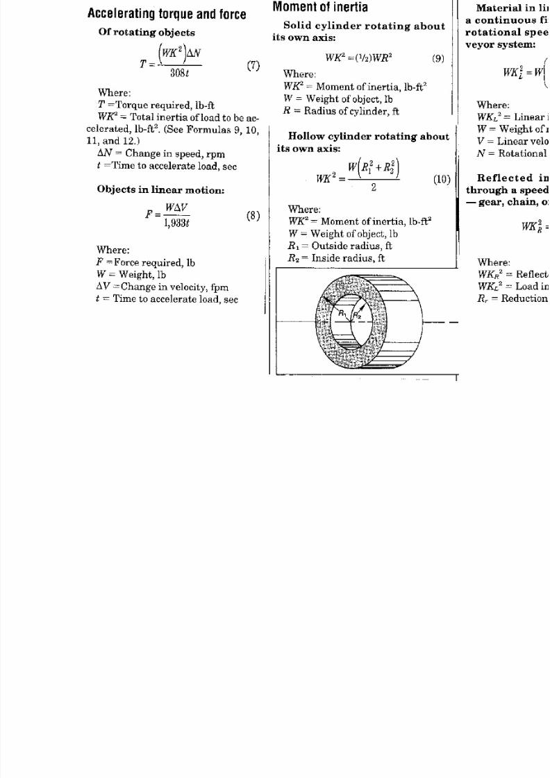
For a solid cylinder
I= M(k^2) = ½ M (R^2) where
R= radius
M= massK= radius of gyration
For a hollow cylinder
I = M(k^2) = ½ M(R1^2 + R2^2)
Note: this intuitively seems like it should be (R1^2 – R2^2)
but that is not the case. Deriving this is a good review of basic
calculus.
7/27/2019 ASABE PE REVIEW�MACHINE DESIGN
http://slidepdf.com/reader/full/asabe-pe-reviewmachine-design 10/80
7/27/2019 ASABE PE REVIEW�MACHINE DESIGN
http://slidepdf.com/reader/full/asabe-pe-reviewmachine-design 11/80
7/27/2019 ASABE PE REVIEW�MACHINE DESIGN
http://slidepdf.com/reader/full/asabe-pe-reviewmachine-design 12/80
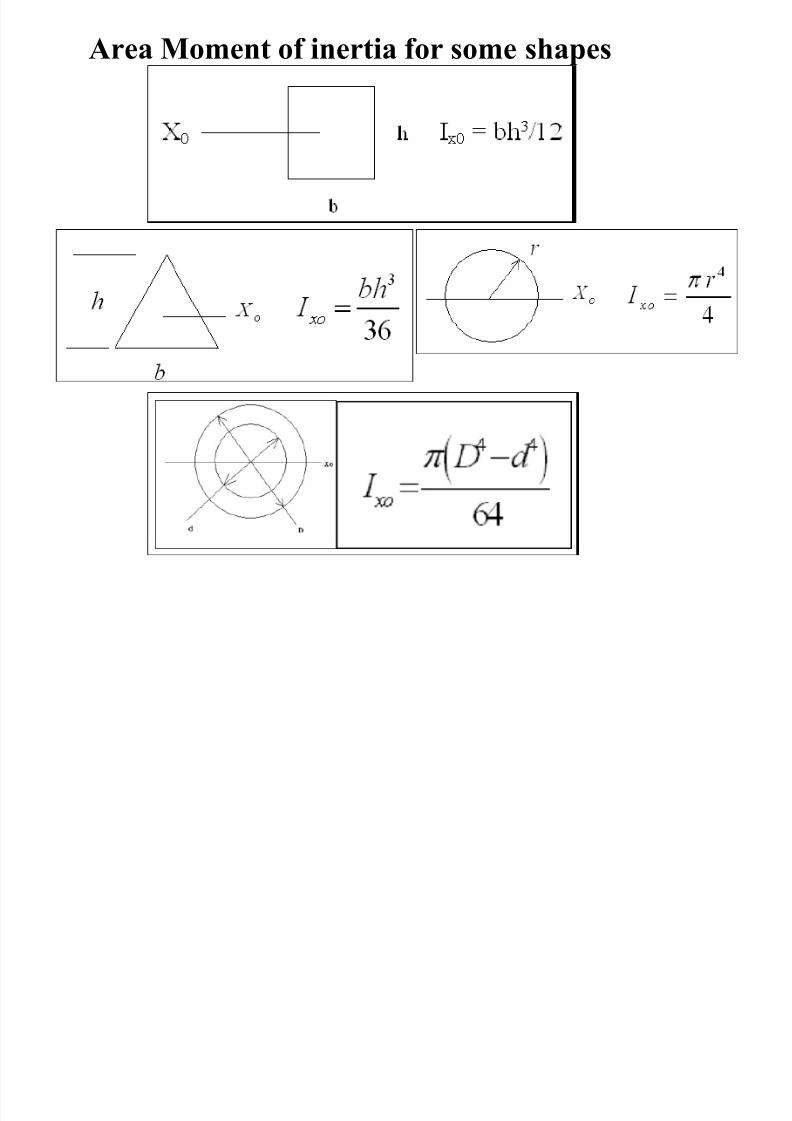
Area Moment of inertia for some shapes
7/27/2019 ASABE PE REVIEW�MACHINE DESIGN
http://slidepdf.com/reader/full/asabe-pe-reviewmachine-design 13/80
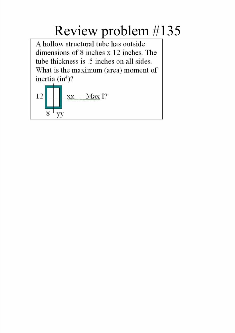
Review problem #135
7/27/2019 ASABE PE REVIEW�MACHINE DESIGN
http://slidepdf.com/reader/full/asabe-pe-reviewmachine-design 14/80
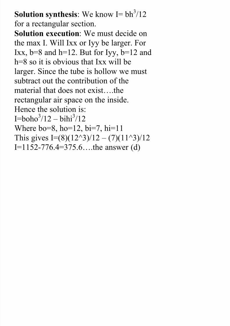
Solution synthesis: We know I= bh3/12
for a rectangular section.
Solution execution: We must decide on
the max I. Will Ixx or Iyy be larger. For Ixx, b=8 and h=12. But for Iyy, b=12 and
h=8 so it is obvious that Ixx will be
larger. Since the tube is hollow we must
subtract out the contribution of thematerial that does not exist….the
rectangular air space on the inside.
Hence the solution is:
I=boho3
/12 – bihi3
/12Where bo=8, ho=12, bi=7, hi=11
This gives I=(8)(12^3)/12 – (7)(11^3)/12
I=1152-776.4=375.6….the answer (d)
7/27/2019 ASABE PE REVIEW�MACHINE DESIGN
http://slidepdf.com/reader/full/asabe-pe-reviewmachine-design 15/80
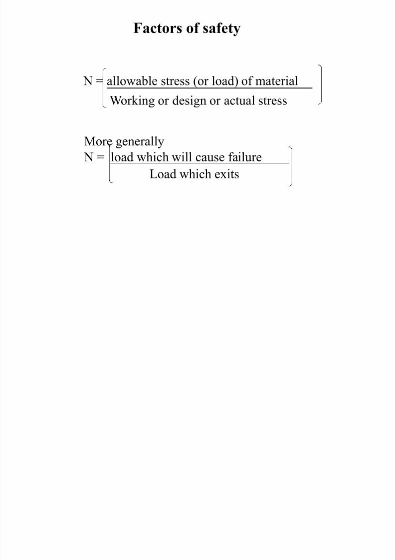
Factors of safety
N = allowable stress (or load) of material
Working or design or actual stress
More generally N = load which will cause failure
Load which exits
7/27/2019 ASABE PE REVIEW�MACHINE DESIGN
http://slidepdf.com/reader/full/asabe-pe-reviewmachine-design 16/80
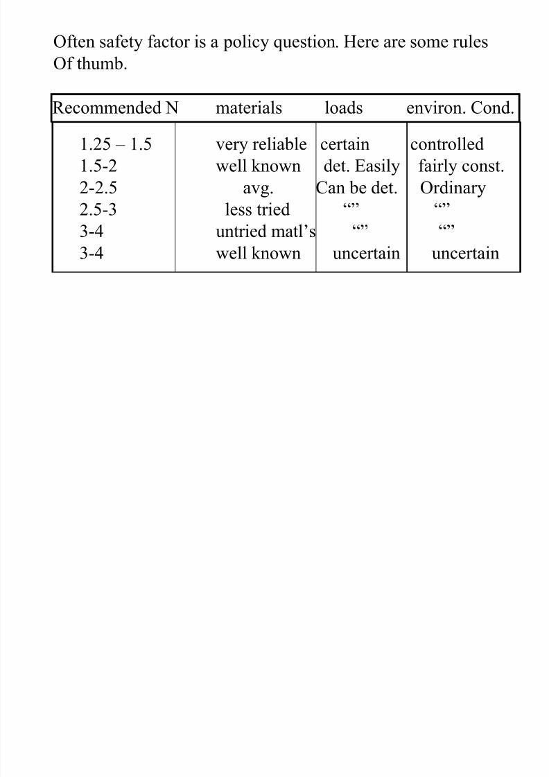
Often safety factor is a policy question. Here are some rules
Of thumb.
Recommended N materials loads environ. Cond.
1.25 – 1.5 very reliable certain controlled
1.5-2 well known det. Easily fairly const.
2-2.5 avg. Can be det. Ordinary2.5-3 less tried ―‖ ―‖
3-4 untried matl’s ―‖ ―‖
3-4 well known uncertain uncertain
7/27/2019 ASABE PE REVIEW�MACHINE DESIGN
http://slidepdf.com/reader/full/asabe-pe-reviewmachine-design 17/80
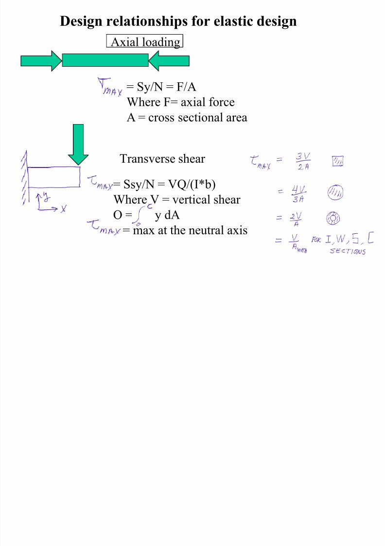
Design relationships for elastic design
Axial loading
= Sy/N = F/A
Where F= axial force
A = cross sectional area
Transverse shear
= Ssy/N = VQ/(I*b)
Where V = vertical shear Q = y dA
= max at the neutral axis
7/27/2019 ASABE PE REVIEW�MACHINE DESIGN
http://slidepdf.com/reader/full/asabe-pe-reviewmachine-design 18/80
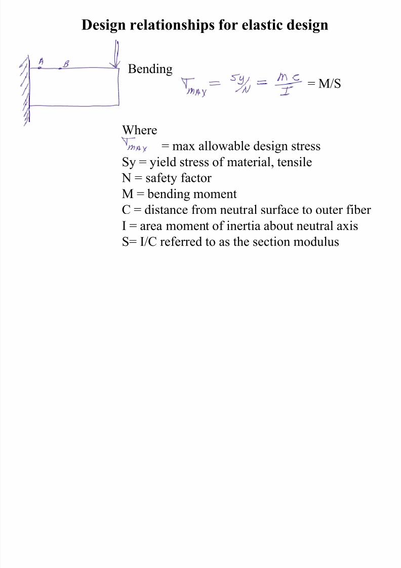
Design relationships for elastic design
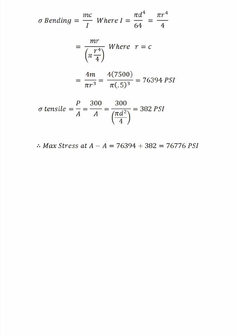
Bending
Where
= max allowable design stress
Sy = yield stress of material, tensile
N = safety factor
M = bending moment
C = distance from neutral surface to outer fiber I = area moment of inertia about neutral axis
S= I/C referred to as the section modulus
= M/S
7/27/2019 ASABE PE REVIEW�MACHINE DESIGN
http://slidepdf.com/reader/full/asabe-pe-reviewmachine-design 19/80
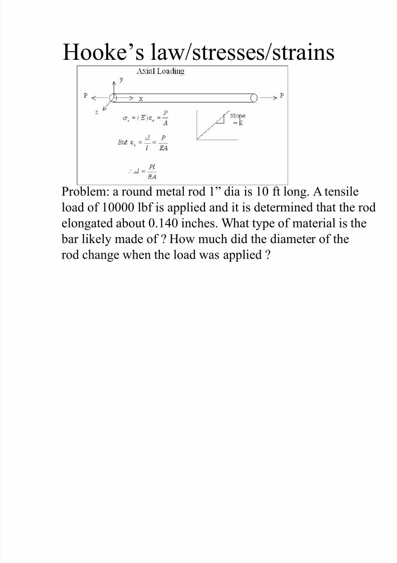
Hooke’s law/stresses/strains
Problem: a round metal rod 1‖ dia is 10 ft long. A tensile
load of 10000 lbf is applied and it is determined that the rodelongated about 0.140 inches. What type of material is the
bar likely made of ? How much did the diameter of the
rod change when the load was applied ?
7/27/2019 ASABE PE REVIEW�MACHINE DESIGN
http://slidepdf.com/reader/full/asabe-pe-reviewmachine-design 20/80
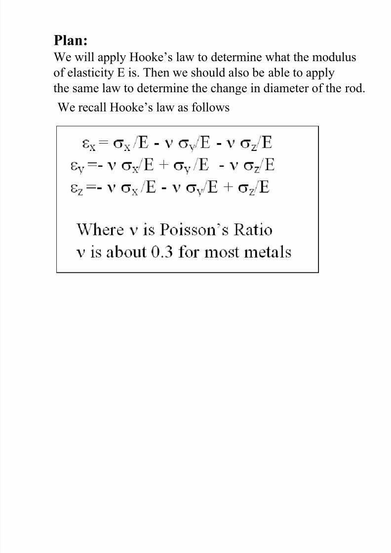
Plan:We will apply Hooke’s law to determine what the modulus
of elasticity E is. Then we should also be able to applythe same law to determine the change in diameter of the rod.
We recall Hooke’s law as follows
7/27/2019 ASABE PE REVIEW�MACHINE DESIGN
http://slidepdf.com/reader/full/asabe-pe-reviewmachine-design 21/80
7/27/2019 ASABE PE REVIEW�MACHINE DESIGN
http://slidepdf.com/reader/full/asabe-pe-reviewmachine-design 22/80
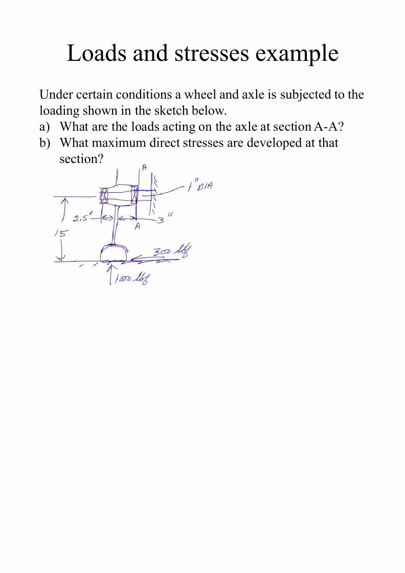
Loads and stresses example
Under certain conditions a wheel and axle is subjected to the
loading shown in the sketch below.
a) What are the loads acting on the axle at section A-A?
b) What maximum direct stresses are developed at thatsection?
7/27/2019 ASABE PE REVIEW�MACHINE DESIGN
http://slidepdf.com/reader/full/asabe-pe-reviewmachine-design 23/80
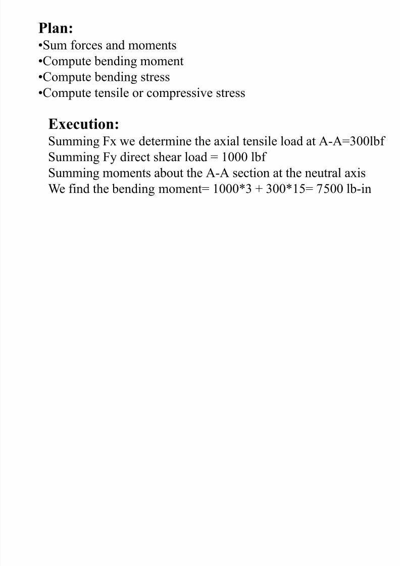
Plan:•Sum forces and moments
•Compute bending moment
•Compute bending stress
•Compute tensile or compressive stress
Execution:
Summing Fx we determine the axial tensile load at A-A=300lbf Summing Fy direct shear load = 1000 lbf
Summing moments about the A-A section at the neutral axis
We find the bending moment= 1000*3 + 300*15= 7500 lb-in
7/27/2019 ASABE PE REVIEW�MACHINE DESIGN
http://slidepdf.com/reader/full/asabe-pe-reviewmachine-design 24/80
7/27/2019 ASABE PE REVIEW�MACHINE DESIGN
http://slidepdf.com/reader/full/asabe-pe-reviewmachine-design 25/80
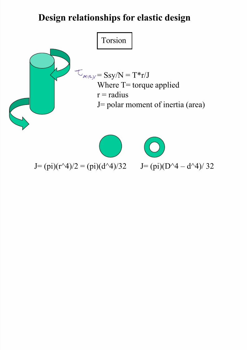
Design relationships for elastic design
Torsion
= Ssy/N = T*r/J
Where T= torque appliedr = radius
J= polar moment of inertia (area)
J= (pi)(r^4)/2 = (pi)(d^4)/32 J= (pi)(D^4 – d^4)/ 32
7/27/2019 ASABE PE REVIEW�MACHINE DESIGN
http://slidepdf.com/reader/full/asabe-pe-reviewmachine-design 26/80
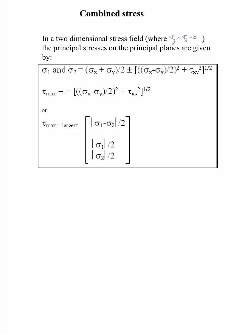
Combined stress
In a two dimensional stress field (where )the principal stresses on the principal planes are given
by:
7/27/2019 ASABE PE REVIEW�MACHINE DESIGN
http://slidepdf.com/reader/full/asabe-pe-reviewmachine-design 27/80
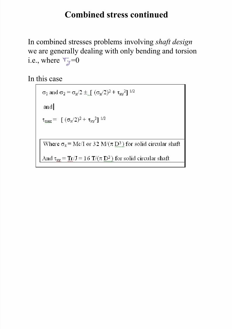
Combined stress continued
In combined stresses problems involving shaft designwe are generally dealing with only bending and torsion
i.e., where =0
In this case
7/27/2019 ASABE PE REVIEW�MACHINE DESIGN
http://slidepdf.com/reader/full/asabe-pe-reviewmachine-design 28/80
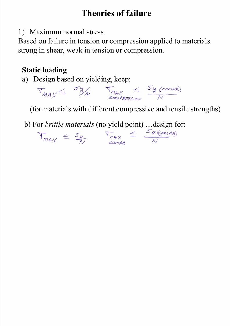
Theories of failure
1) Maximum normal stress
Based on failure in tension or compression applied to materialsstrong in shear, weak in tension or compression.
Static loading
a) Design based on yielding, keep:
(for materials with different compressive and tensile strengths)
b) For brittle materials (no yield point) …design for:
7/27/2019 ASABE PE REVIEW�MACHINE DESIGN
http://slidepdf.com/reader/full/asabe-pe-reviewmachine-design 29/80
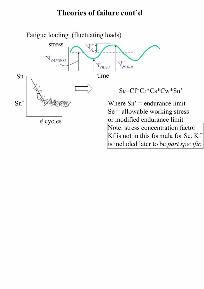
Theories of failure cont’d
Fatigue loading (fluctuating loads)
Se=Cf*Cr*Cs*Cw*Sn’
Where Sn’ = endurance limit
Se = allowable working stress
or modified endurance limit
Note: stress concentration factor
Kf is not in this formula for Se. Kf
is included later to be part specific
Sn
Sn’
# cycles
time
stress

7/27/2019 ASABE PE REVIEW�MACHINE DESIGN
http://slidepdf.com/reader/full/asabe-pe-reviewmachine-design 30/80
Soderberg failure line for fatigue
safe stress line
SeSe/N
axis
Syp/N Syp
State of stressKf* ,
Kf
7/27/2019 ASABE PE REVIEW�MACHINE DESIGN
http://slidepdf.com/reader/full/asabe-pe-reviewmachine-design 31/80
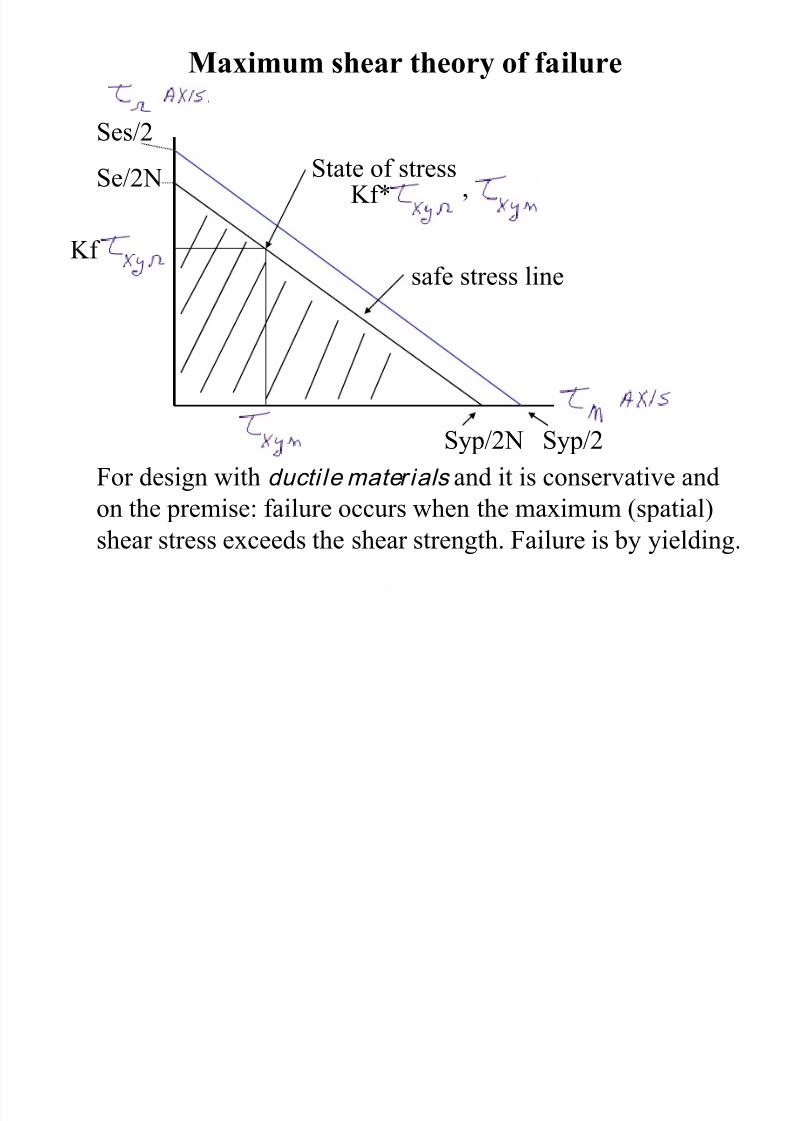
Maximum shear theory of failure
For design with ducti le mater ials and it is conservative and
on the premise: failure occurs when the maximum (spatial)
shear stress exceeds the shear strength. Failure is by yielding.
safe stress line
Ses/2Se/2N
axis
Syp/2N Syp/2
State of stressKf* ,
Kf

7/27/2019 ASABE PE REVIEW�MACHINE DESIGN
http://slidepdf.com/reader/full/asabe-pe-reviewmachine-design 32/80
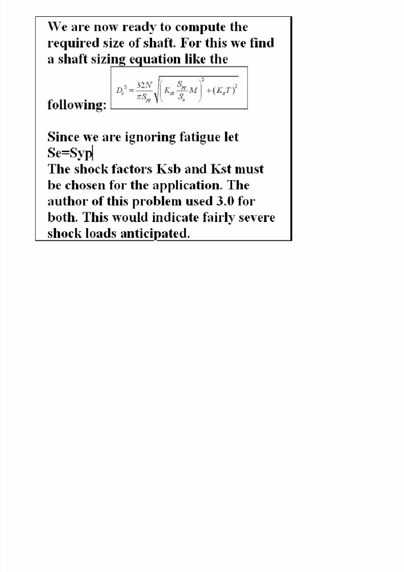
Formulae for sizing a shaft carrying bending
bending and torsion
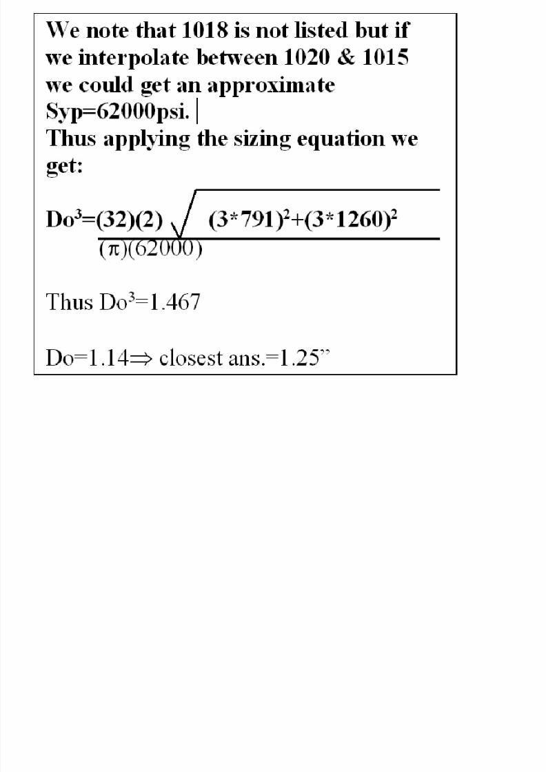
For a hollow shaft….‖Do‖=outside dia, ―Di‖ = inside dia
For a solid shaft Di=0 and the equation becomes:
Where ―Do‖ will be the smallest allowable diameter based on
max shear theory. M is the bending moment and T is the torsion
T is the mean torque assumed to be steady here…and M is the
Bending moment which becomes the fluctuating load as the shaft
Rotates.

7/27/2019 ASABE PE REVIEW�MACHINE DESIGN
http://slidepdf.com/reader/full/asabe-pe-reviewmachine-design 33/80
Other shaft sizing considerations
Other criterion of shaft design may be requirements on torsional
Rigidity (twist) and lateral rigidity (deflection)
Torsional rigidity
Where:
theta= angle of twist, degrees
L = length (carrying torque), in inches
T = torsional moment, lb-in
G = torsional (shear) modulus of elasticity
(11.5x10^6 psi, steels) ( 3.8x10^6 psi, Al alloys
D = shaft diameter, inches
Theta = 584* T*L/(G*(Do^4-Di^4)) for hollow circ. shaft
Theta = 584* T*L/(G*(Do^4)) for solid circ. shaft
7/27/2019 ASABE PE REVIEW�MACHINE DESIGN
http://slidepdf.com/reader/full/asabe-pe-reviewmachine-design 34/80
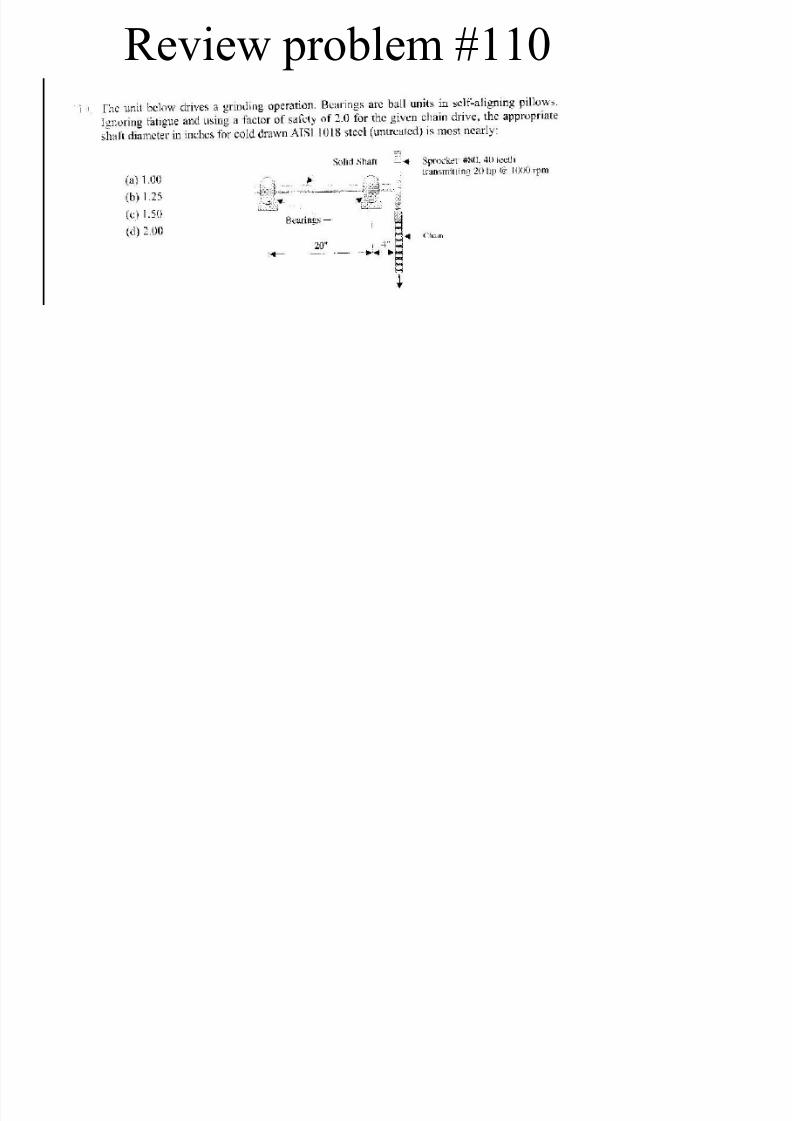
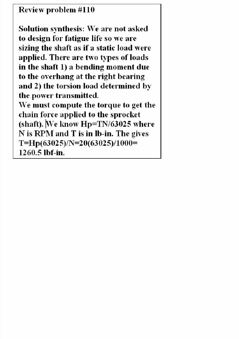
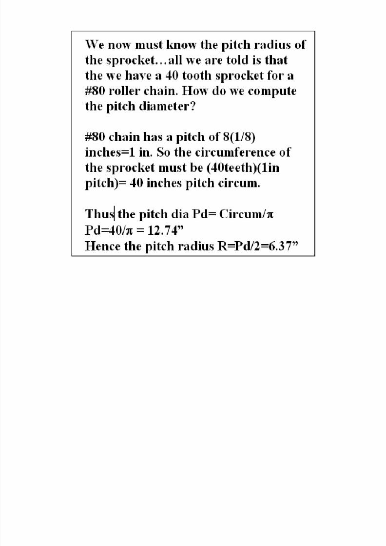
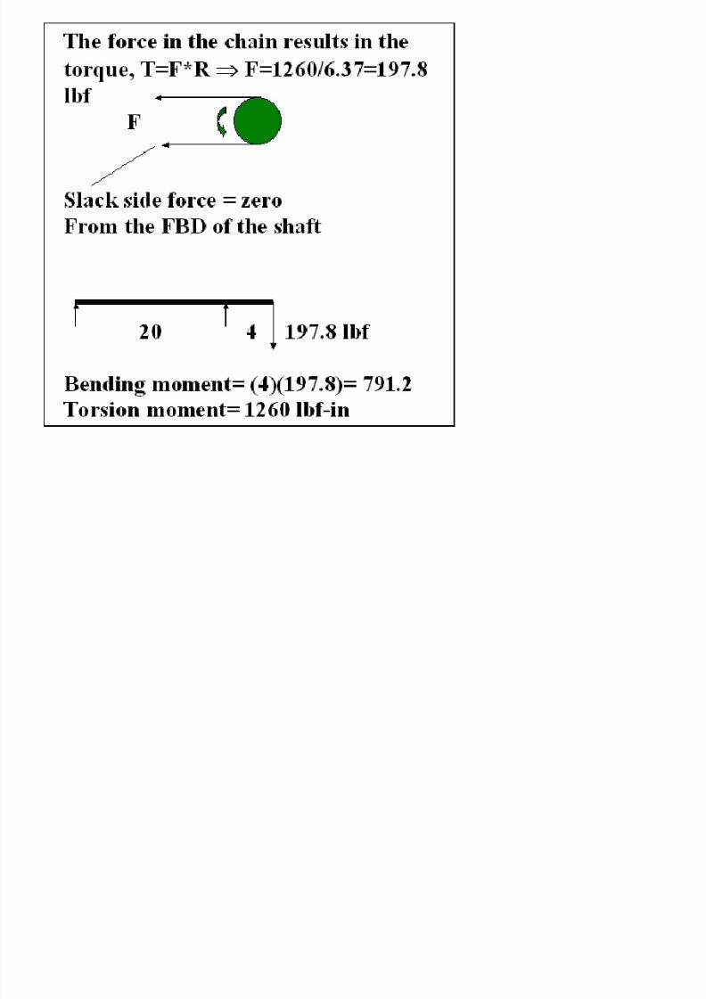
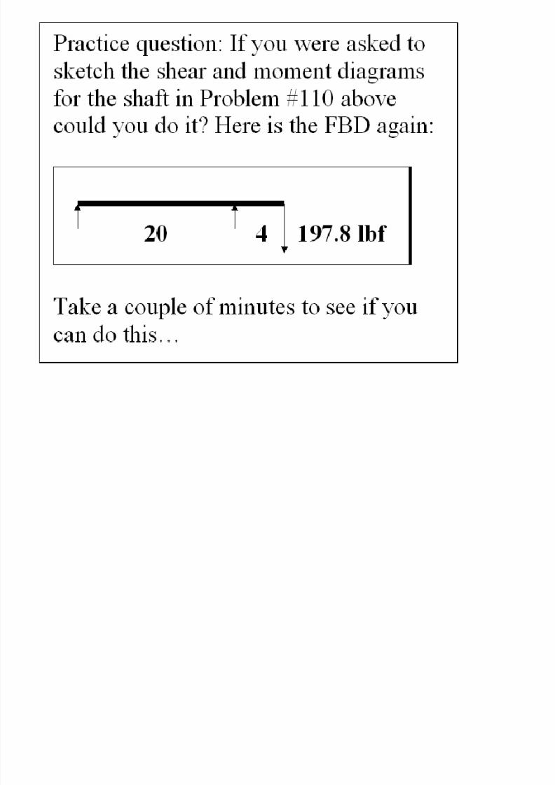
Review problem #110
7/27/2019 ASABE PE REVIEW�MACHINE DESIGN
http://slidepdf.com/reader/full/asabe-pe-reviewmachine-design 35/80
7/27/2019 ASABE PE REVIEW�MACHINE DESIGN
http://slidepdf.com/reader/full/asabe-pe-reviewmachine-design 36/80
7/27/2019 ASABE PE REVIEW�MACHINE DESIGN
http://slidepdf.com/reader/full/asabe-pe-reviewmachine-design 37/80
7/27/2019 ASABE PE REVIEW�MACHINE DESIGN
http://slidepdf.com/reader/full/asabe-pe-reviewmachine-design 38/80
7/27/2019 ASABE PE REVIEW�MACHINE DESIGN
http://slidepdf.com/reader/full/asabe-pe-reviewmachine-design 39/80
7/27/2019 ASABE PE REVIEW�MACHINE DESIGN
http://slidepdf.com/reader/full/asabe-pe-reviewmachine-design 40/80
7/27/2019 ASABE PE REVIEW�MACHINE DESIGN
http://slidepdf.com/reader/full/asabe-pe-reviewmachine-design 41/80
7/27/2019 ASABE PE REVIEW�MACHINE DESIGN
http://slidepdf.com/reader/full/asabe-pe-reviewmachine-design 42/80
7/27/2019 ASABE PE REVIEW�MACHINE DESIGN
http://slidepdf.com/reader/full/asabe-pe-reviewmachine-design 43/80
7/27/2019 ASABE PE REVIEW�MACHINE DESIGN
http://slidepdf.com/reader/full/asabe-pe-reviewmachine-design 44/80
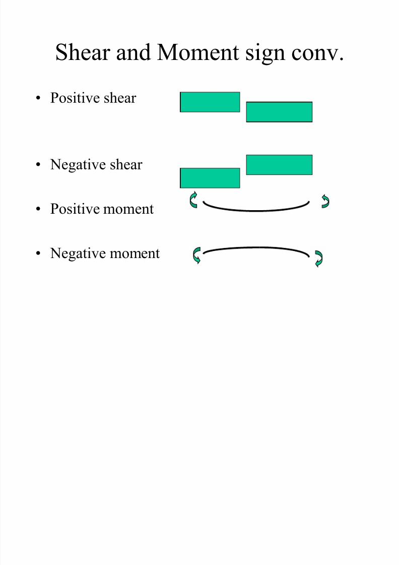
Shear and Moment sign conv.
• Positive shear
• Negative shear
• Positive moment
• Negative moment
7/27/2019 ASABE PE REVIEW�MACHINE DESIGN
http://slidepdf.com/reader/full/asabe-pe-reviewmachine-design 45/80
7/27/2019 ASABE PE REVIEW�MACHINE DESIGN
http://slidepdf.com/reader/full/asabe-pe-reviewmachine-design 46/80
7/27/2019 ASABE PE REVIEW�MACHINE DESIGN
http://slidepdf.com/reader/full/asabe-pe-reviewmachine-design 47/80
7/27/2019 ASABE PE REVIEW�MACHINE DESIGN
http://slidepdf.com/reader/full/asabe-pe-reviewmachine-design 48/80
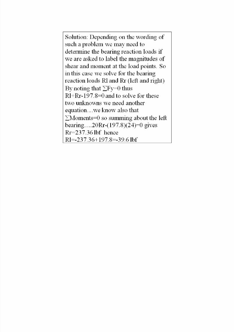
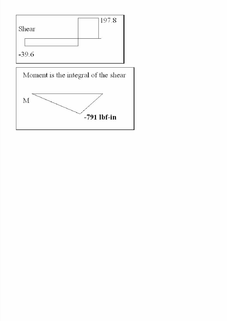
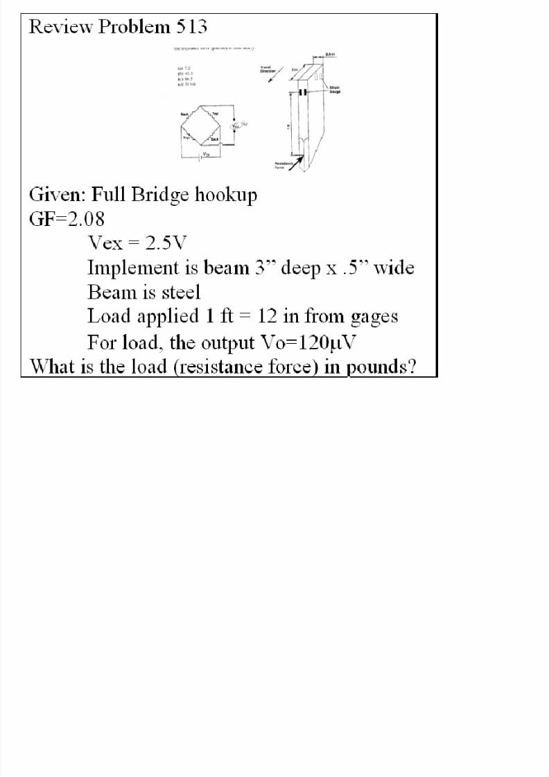
Problem: If the above implement problem had been given
this same Vo for a half-bridge circuit what would have been
the force acting on the implement?
7/27/2019 ASABE PE REVIEW�MACHINE DESIGN
http://slidepdf.com/reader/full/asabe-pe-reviewmachine-design 49/80
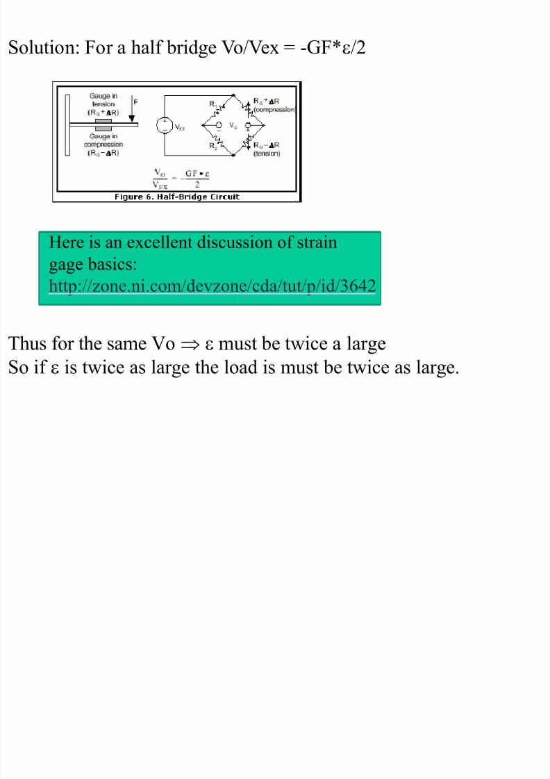
Solution: For a half bridge Vo/Vex = -GF*/2
Here is an excellent discussion of strain
gage basics:
http://zone.ni.com/devzone/cda/tut/p/id/3642
Thus for the same Vo must be twice a large
So if is twice as large the load is must be twice as large.
7/27/2019 ASABE PE REVIEW�MACHINE DESIGN
http://slidepdf.com/reader/full/asabe-pe-reviewmachine-design 50/80
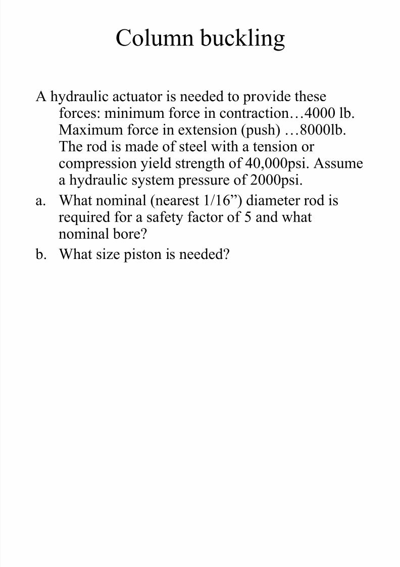
Column buckling
A hydraulic actuator is needed to provide theseforces: minimum force in contraction…4000 lb.Maximum force in extension (push) …8000lb.
The rod is made of steel with a tension or compression yield strength of 40,000psi. Assumea hydraulic system pressure of 2000psi.
a. What nominal (nearest 1/16‖) diameter rod is
required for a safety factor of 5 and whatnominal bore?
b. What size piston is needed?
7/27/2019 ASABE PE REVIEW�MACHINE DESIGN
http://slidepdf.com/reader/full/asabe-pe-reviewmachine-design 51/80
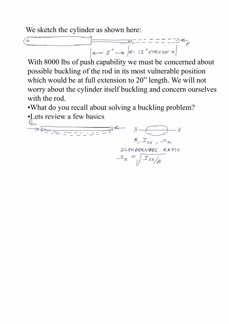
We sketch the cylinder as shown here:
With 8000 lbs of push capability we must be concerned about
possible buckling of the rod in its most vulnerable position
which would be at full extension to 20‖ length. We will notworry about the cylinder itself buckling and concern ourselves
with the rod.
•What do you recall about solving a buckling problem?
•Lets review a few basics
7/27/2019 ASABE PE REVIEW�MACHINE DESIGN
http://slidepdf.com/reader/full/asabe-pe-reviewmachine-design 52/80
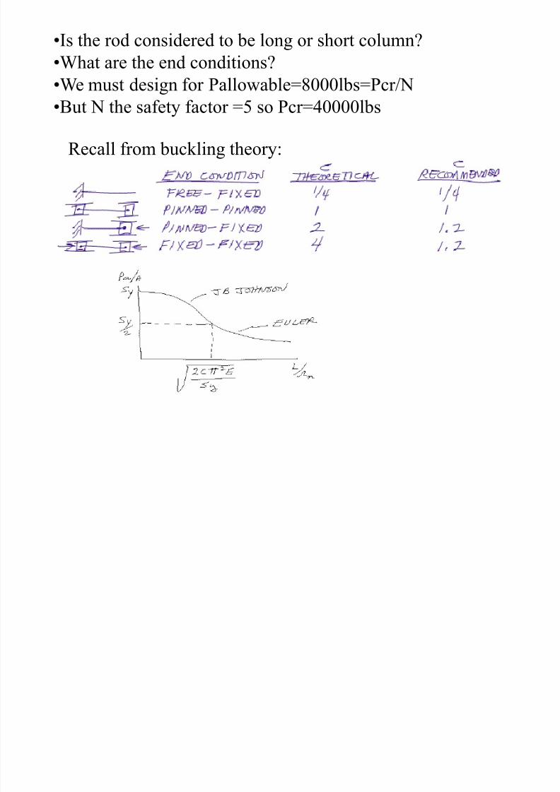
•Is the rod considered to be long or short column?
•What are the end conditions?
•We must design for Pallowable=8000lbs=Pcr/N
•But N the safety factor =5 so Pcr=40000lbs
Recall from buckling theory:
7/27/2019 ASABE PE REVIEW�MACHINE DESIGN
http://slidepdf.com/reader/full/asabe-pe-reviewmachine-design 53/80
7/27/2019 ASABE PE REVIEW�MACHINE DESIGN
http://slidepdf.com/reader/full/asabe-pe-reviewmachine-design 54/80
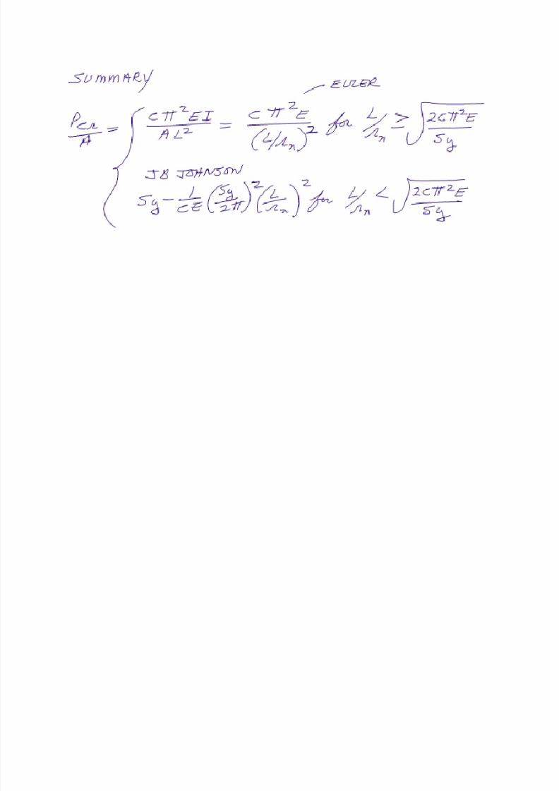
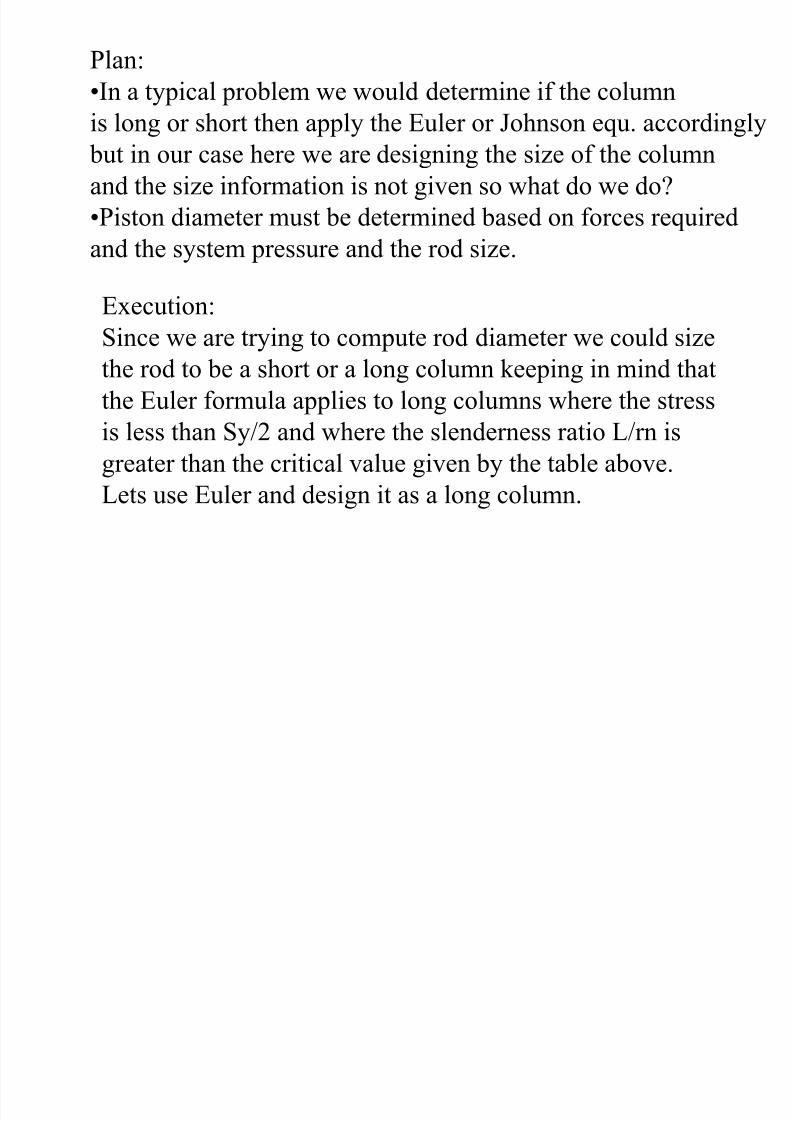
Plan:
•In a typical problem we would determine if the column
is long or short then apply the Euler or Johnson equ. accordingly
but in our case here we are designing the size of the columnand the size information is not given so what do we do?
•Piston diameter must be determined based on forces required
and the system pressure and the rod size.
Execution:
Since we are trying to compute rod diameter we could size
the rod to be a short or a long column keeping in mind that
the Euler formula applies to long columns where the stress
is less than Sy/2 and where the slenderness ratio L/rn is
greater than the critical value given by the table above.
Lets use Euler and design it as a long column.
7/27/2019 ASABE PE REVIEW�MACHINE DESIGN
http://slidepdf.com/reader/full/asabe-pe-reviewmachine-design 55/80
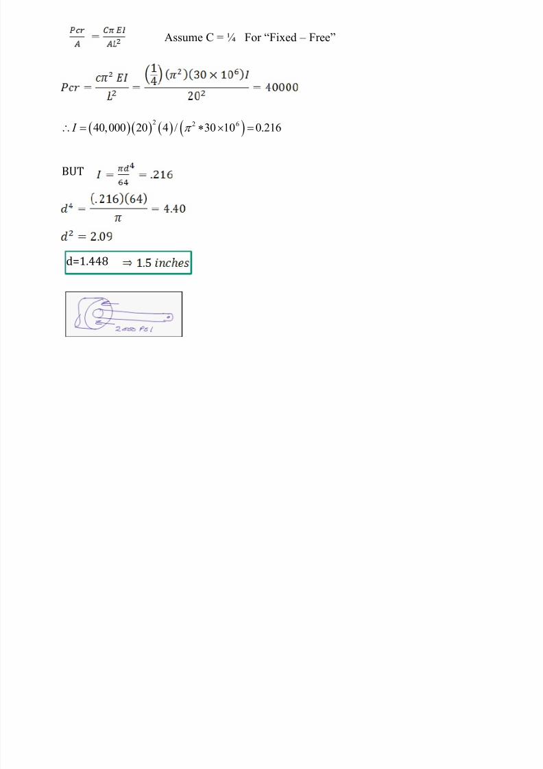
Assume C = ¼ For ―Fixed – Free‖
BUT
d=1.448
2 2 640,000 20 4 / 30 10 0.216 I
7/27/2019 ASABE PE REVIEW�MACHINE DESIGN
http://slidepdf.com/reader/full/asabe-pe-reviewmachine-design 56/80
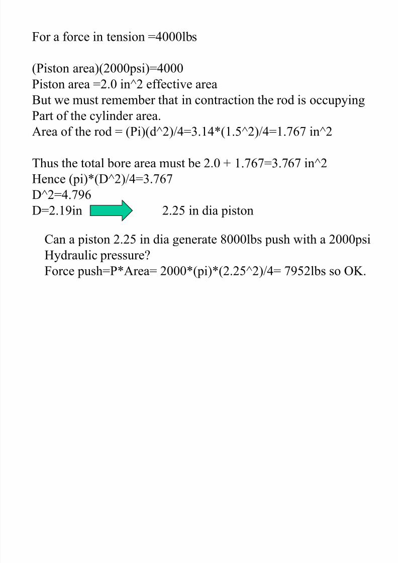
For a force in tension =4000lbs
(Piston area)(2000psi)=4000Piston area =2.0 in^2 effective area
But we must remember that in contraction the rod is occupying
Part of the cylinder area.
Area of the rod = (Pi)(d^2)/4=3.14*(1.5^2)/4=1.767 in^2
Thus the total bore area must be 2.0 + 1.767=3.767 in^2
Hence (pi)*(D^2)/4=3.767
D^2=4.796
D=2.19in ------- 2.25 in dia piston
Can a piston 2.25 in dia generate 8000lbs push with a 2000psi
Hydraulic pressure?
Force push=P*Area= 2000*(pi)*(2.25^2)/4= 7952lbs so OK.

7/27/2019 ASABE PE REVIEW�MACHINE DESIGN
http://slidepdf.com/reader/full/asabe-pe-reviewmachine-design 57/80
7/27/2019 ASABE PE REVIEW�MACHINE DESIGN
http://slidepdf.com/reader/full/asabe-pe-reviewmachine-design 58/80
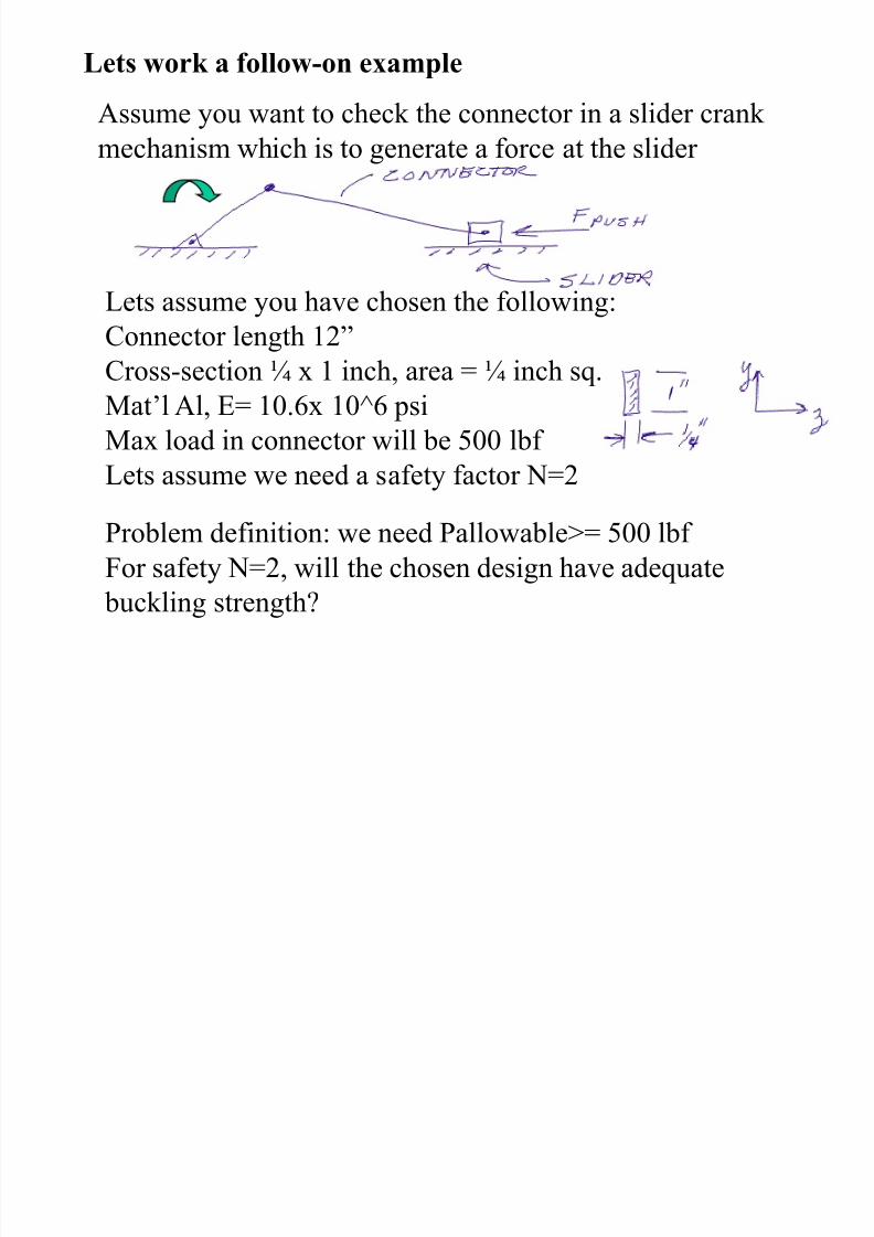
Lets work a follow-on example
Assume you want to check the connector in a slider crank
mechanism which is to generate a force at the slider
Lets assume you have chosen the following:Connector length 12‖
Cross-section ¼ x 1 inch, area = ¼ inch sq.
Mat’l Al, E= 10.6x 10^6 psi
Max load in connector will be 500 lbf
Lets assume we need a safety factor N=2
Problem definition: we need Pallowable>= 500 lbf
For safety N=2, will the chosen design have adequate
buckling strength?
Plan:
7/27/2019 ASABE PE REVIEW�MACHINE DESIGN
http://slidepdf.com/reader/full/asabe-pe-reviewmachine-design 59/80
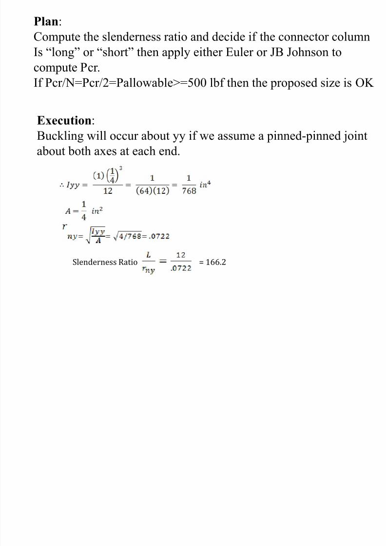
Plan:
Compute the slenderness ratio and decide if the connector column
Is ―long‖ or ―short‖ then apply either Euler or JB Johnson to
compute Pcr.If Pcr/N=Pcr/2=Pallowable>=500 lbf then the proposed size is OK
Execution:
Buckling will occur about yy if we assume a pinned-pinned jointabout both axes at each end.
Slenderness Ratio = 166.2
7/27/2019 ASABE PE REVIEW�MACHINE DESIGN
http://slidepdf.com/reader/full/asabe-pe-reviewmachine-design 60/80
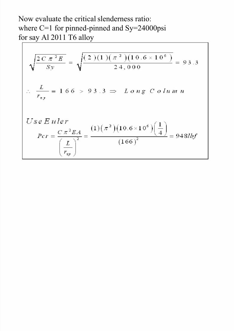
Now evaluate the critical slenderness ratio:
where C=1 for pinned-pinned and Sy=24000psi
for say Al 2011 T6 alloy
7/27/2019 ASABE PE REVIEW�MACHINE DESIGN
http://slidepdf.com/reader/full/asabe-pe-reviewmachine-design 61/80
If b k d it th l d ti i t f th
7/27/2019 ASABE PE REVIEW�MACHINE DESIGN
http://slidepdf.com/reader/full/asabe-pe-reviewmachine-design 62/80
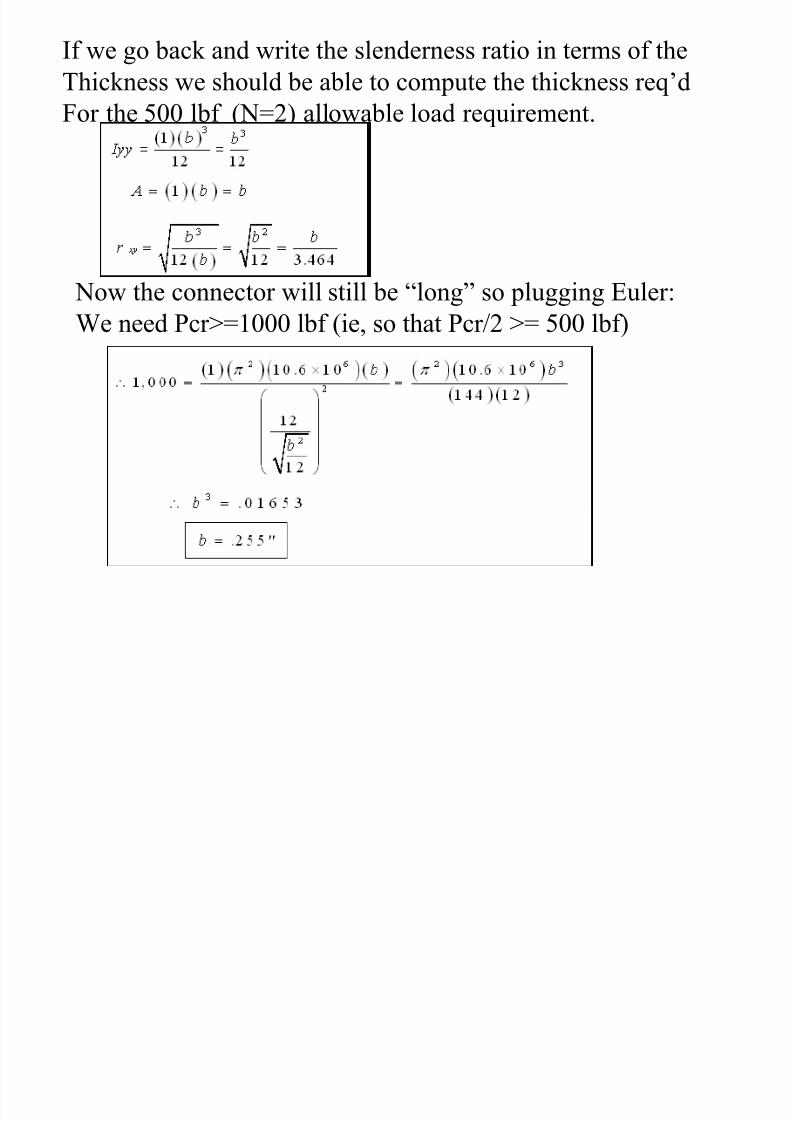
If we go back and write the slenderness ratio in terms of the
Thickness we should be able to compute the thickness req’d
For the 500 lbf (N=2) allowable load requirement.
Now the connector will still be ―long‖ so plugging Euler: We need Pcr>=1000 lbf (ie, so that Pcr/2 >= 500 lbf)
7/27/2019 ASABE PE REVIEW�MACHINE DESIGN
http://slidepdf.com/reader/full/asabe-pe-reviewmachine-design 63/80
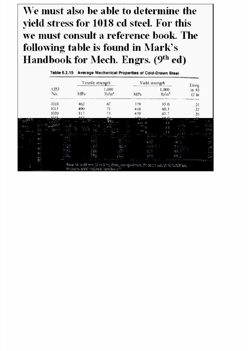
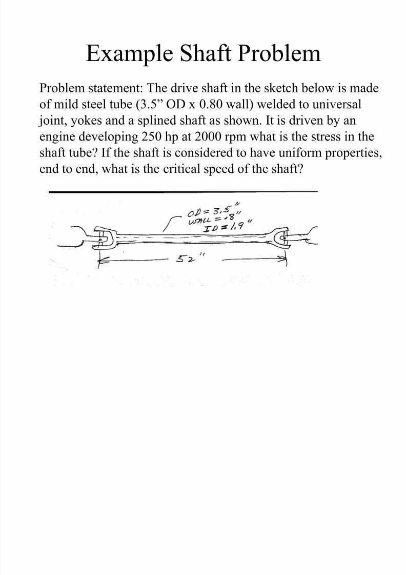
Example Shaft Problem
Problem statement: The drive shaft in the sketch below is made
of mild steel tube (3.5‖ OD x 0.80 wall) welded to universal
joint, yokes and a splined shaft as shown. It is driven by an
engine developing 250 hp at 2000 rpm what is the stress in the
shaft tube? If the shaft is considered to have uniform properties,
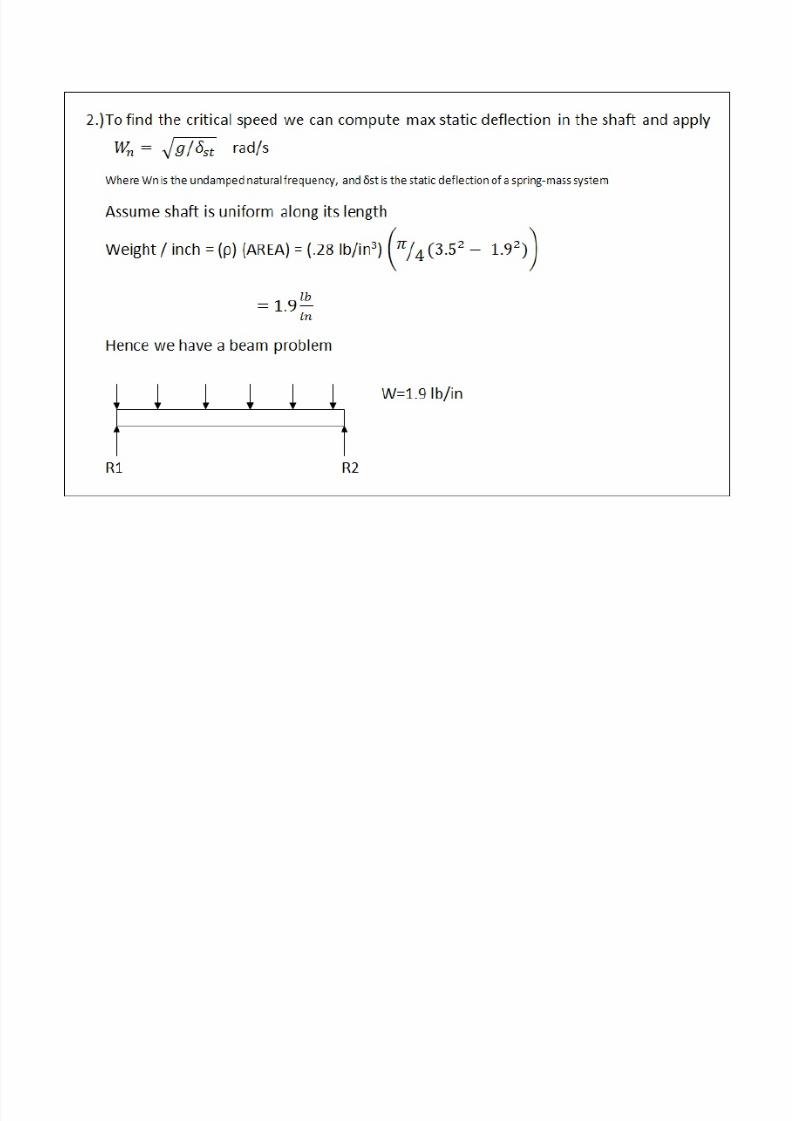
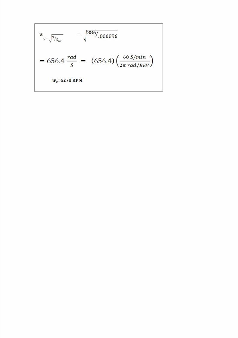
end to end, what is the critical speed of the shaft?
7/27/2019 ASABE PE REVIEW�MACHINE DESIGN
http://slidepdf.com/reader/full/asabe-pe-reviewmachine-design 64/80
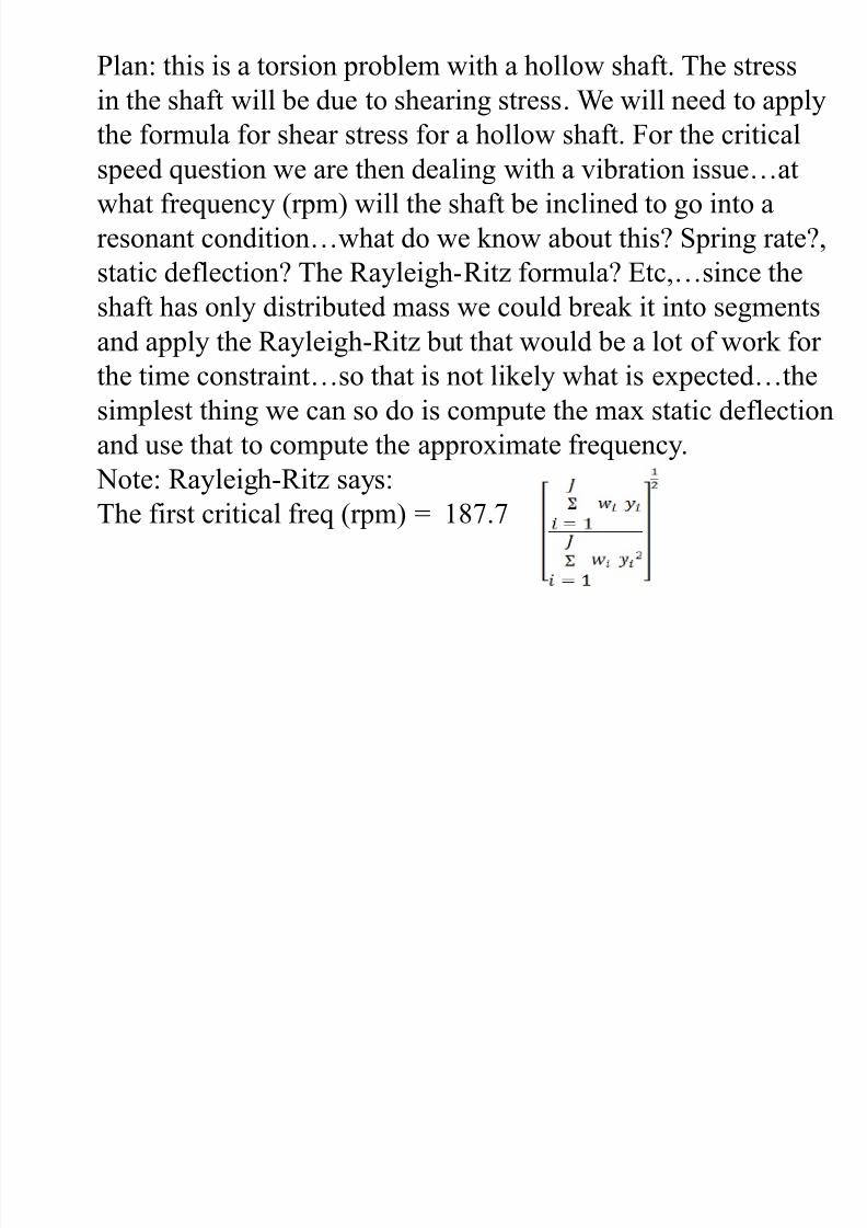
Plan: this is a torsion problem with a hollow shaft. The stress
in the shaft will be due to shearing stress. We will need to apply
the formula for shear stress for a hollow shaft. For the critical
speed question we are then dealing with a vibration issue…at what frequency (rpm) will the shaft be inclined to go into a
resonant condition…what do we know about this? Spring rate?,
static deflection? The Rayleigh-Ritz formula? Etc,…since the
shaft has only distributed mass we could break it into segmentsand apply the Rayleigh-Ritz but that would be a lot of work for
the time constraint…so that is not likely what is expected…the
simplest thing we can so do is compute the max static deflection
and use that to compute the approximate frequency.
Note: Rayleigh-Ritz says:
The first critical freq (rpm) = 187.7
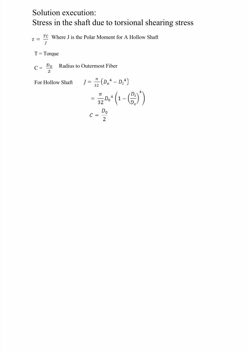
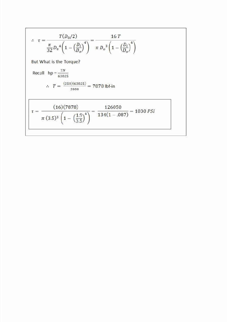
Solution execution:
7/27/2019 ASABE PE REVIEW�MACHINE DESIGN
http://slidepdf.com/reader/full/asabe-pe-reviewmachine-design 65/80
Where J is the Polar Moment for A Hollow Shaft
T = Torque
C = Radius to Outermost Fiber
For Hollow Shaft
Solution execution:
Stress in the shaft due to torsional shearing stress
7/27/2019 ASABE PE REVIEW�MACHINE DESIGN
http://slidepdf.com/reader/full/asabe-pe-reviewmachine-design 66/80
7/27/2019 ASABE PE REVIEW�MACHINE DESIGN
http://slidepdf.com/reader/full/asabe-pe-reviewmachine-design 67/80

7/27/2019 ASABE PE REVIEW�MACHINE DESIGN
http://slidepdf.com/reader/full/asabe-pe-reviewmachine-design 68/80
7/27/2019 ASABE PE REVIEW�MACHINE DESIGN
http://slidepdf.com/reader/full/asabe-pe-reviewmachine-design 69/80

7/27/2019 ASABE PE REVIEW�MACHINE DESIGN
http://slidepdf.com/reader/full/asabe-pe-reviewmachine-design 70/80
APPENDIX
7/27/2019 ASABE PE REVIEW�MACHINE DESIGN
http://slidepdf.com/reader/full/asabe-pe-reviewmachine-design 71/80
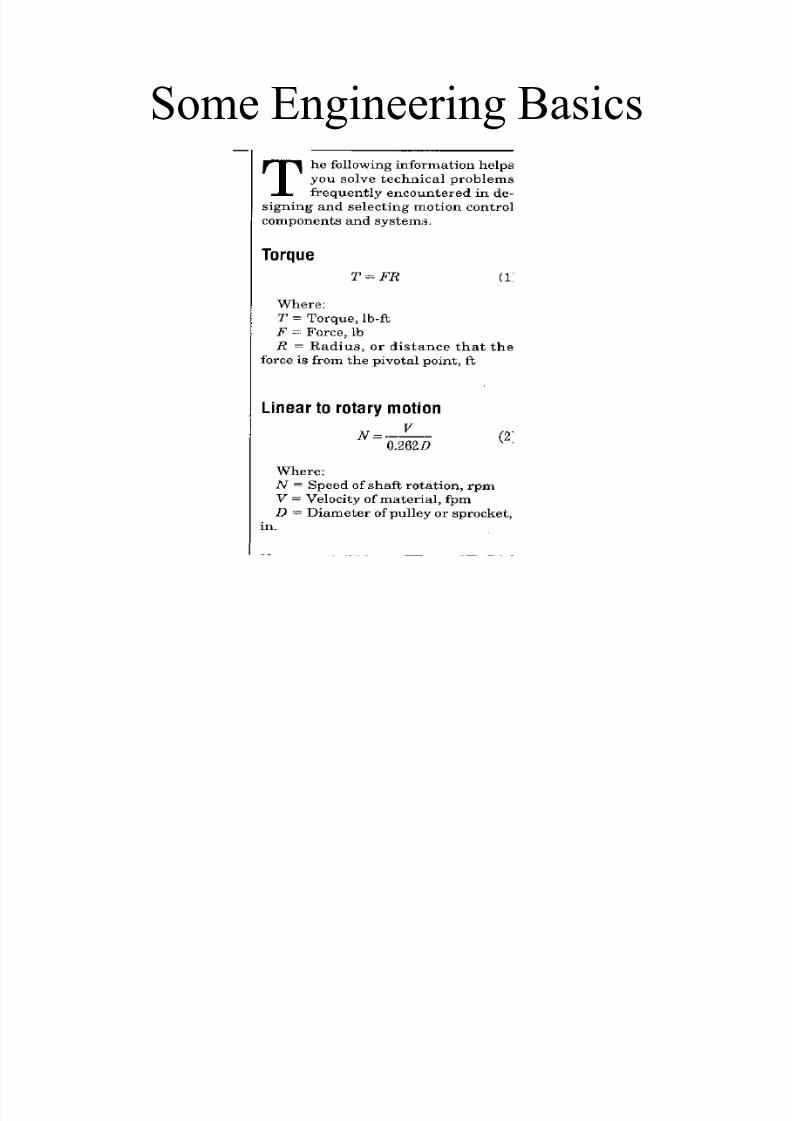
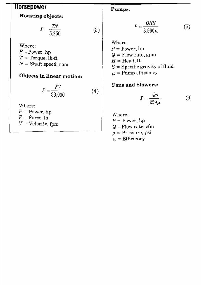
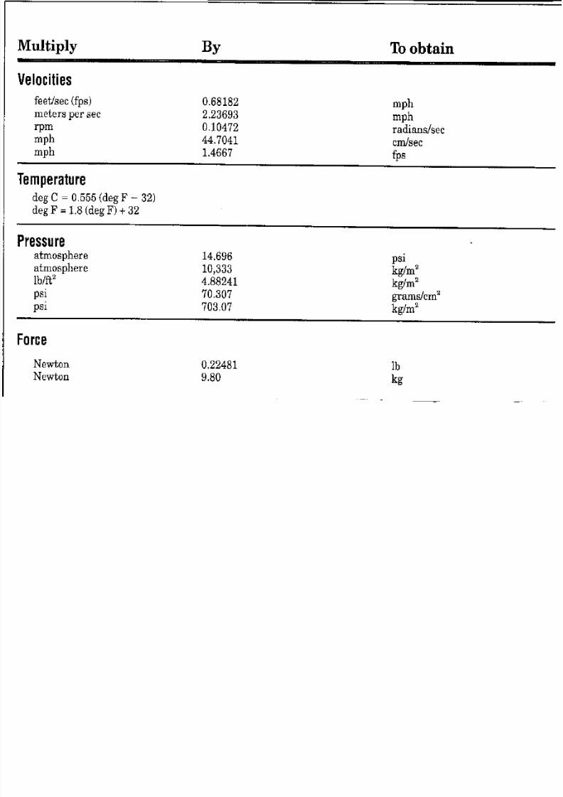
Some Engineering Basics
7/27/2019 ASABE PE REVIEW�MACHINE DESIGN
http://slidepdf.com/reader/full/asabe-pe-reviewmachine-design 72/80
7/27/2019 ASABE PE REVIEW�MACHINE DESIGN
http://slidepdf.com/reader/full/asabe-pe-reviewmachine-design 73/80

7/27/2019 ASABE PE REVIEW�MACHINE DESIGN
http://slidepdf.com/reader/full/asabe-pe-reviewmachine-design 74/80
7/27/2019 ASABE PE REVIEW�MACHINE DESIGN
http://slidepdf.com/reader/full/asabe-pe-reviewmachine-design 75/80
7/27/2019 ASABE PE REVIEW�MACHINE DESIGN
http://slidepdf.com/reader/full/asabe-pe-reviewmachine-design 76/80
7/27/2019 ASABE PE REVIEW�MACHINE DESIGN
http://slidepdf.com/reader/full/asabe-pe-reviewmachine-design 77/80

7/27/2019 ASABE PE REVIEW�MACHINE DESIGN
http://slidepdf.com/reader/full/asabe-pe-reviewmachine-design 78/80
7/27/2019 ASABE PE REVIEW�MACHINE DESIGN
http://slidepdf.com/reader/full/asabe-pe-reviewmachine-design 79/80

7/27/2019 ASABE PE REVIEW�MACHINE DESIGN
http://slidepdf.com/reader/full/asabe-pe-reviewmachine-design 80/80