asent fmeca - raytheon eagle of the fmeca manager . asent fmeca 4 the fmeca toolkit provides most of...
TRANSCRIPT

ASENT FMECA


iii
Table of Contents The FMECA Manager ........................................................................................................................................................................ 1
Using The FMECA Manager .......................................................................................................................................................... 1
FMECA Methodology .................................................................................................................................................................. 1
Starting a New FMECA ............................................................................................................................................................... 1
Overview of the FMECA Manager .............................................................................................................................................. 3
FMECA Manager Menus ............................................................................................................................................................ 6
FMECA Manager Icons and Toolbar ........................................................................................................................................... 7
Tailoring the Presentation ........................................................................................................................................................... 8
Defining the Active Function/Phase ............................................................................................................................................ 8
Finding Items on the Tree ........................................................................................................................................................... 8
Exiting the FMECA Manager .................................................................................................................................................... 10
The Library Editor......................................................................................................................................................................... 10
Overview of the FMECA Library Editor ..................................................................................................................................... 10
Importing Library Data .............................................................................................................................................................. 11
Editing a Record ....................................................................................................................................................................... 15
Finding a Record ...................................................................................................................................................................... 15
Finding Next Record ................................................................................................................................................................. 16
Editing the Component Mapping ............................................................................................................................................... 17
Editing the Detection Codes Library .......................................................................................................................................... 18
Editing the Detection/Isolation Groups Library .......................................................................................................................... 19
Editing the Failure Modes/Effects Library .................................................................................................................................. 19
Editing the Part Types/Failures Library ..................................................................................................................................... 20
Editing the Probability Groups Library ....................................................................................................................................... 21
Editing the RCM Tasks Library ................................................................................................................................................. 21
Editing the Severity Levels Library ............................................................................................................................................ 22
Editing the Signals Library ........................................................................................................................................................ 23
Working with the Product Tree ..................................................................................................................................................... 24
Working with the Project Tree ................................................................................................................................................... 24
FMECA Project Tree: The System Node................................................................................................................................... 24
FMECA Project Tree: Assembly Nodes .................................................................................................................................... 26
FMECA Project Tree: Parts & Signals ....................................................................................................................................... 29
FMECA Project Tree: Failure Mode Nodes ............................................................................................................................... 32
Adding an Assembly ................................................................................................................................................................. 35
Editing an Assembly ................................................................................................................................................................. 37
Assembly Graphics ................................................................................................................................................................... 37
Linking and Unlinking ................................................................................................................................................................ 37
Updating Links .......................................................................................................................................................................... 39
Copying an Assembly ............................................................................................................................................................... 39
Moving an Assembly ................................................................................................................................................................. 40
Deleting an Assembly ............................................................................................................................................................... 40
Importing Subtrees into FMECA ............................................................................................................................................... 41
Parts,Signal & Failure Mode Items ............................................................................................................................................... 45
Adding Parts, Signals, or Failure Modes ................................................................................................................................... 45
Deleting Parts, Signals, or Failure Modes ................................................................................................................................. 47
Deleting a Group of Parts ......................................................................................................................................................... 47
Working with Failure Modes ......................................................................................................................................................... 48

ASENT FMECA
iv
Working with End Effects .......................................................................................................................................................... 48
Editing Failure Mode Data ........................................................................................................................................................ 49
Copying Failure Modes ............................................................................................................................................................. 51
Defining Next Higher Effects ..................................................................................................................................................... 52
Viewing Causes ........................................................................................................................................................................ 54
Viewing the End Effects ............................................................................................................................................................ 55
Creating FMIs ........................................................................................................................................................................... 55
Calculating Criticality Numbers ................................................................................................................................................. 56
Editing Detection Method .......................................................................................................................................................... 57
Editing Remarks/Actions ........................................................................................................................................................... 57
Editing Maintainability Remarks ................................................................................................................................................ 60
Editing Compensating Provisions ............................................................................................................................................. 60
Performing Testability Analyses ................................................................................................................................................... 60
Recommended Methodology for Testability Analysis ................................................................................................................ 60
Defining Detection/Isolation Groups .......................................................................................................................................... 60
Initializing Testability ................................................................................................................................................................. 60
Editing Testability Data ............................................................................................................................................................. 61
To edit the Isolation List: ........................................................................................................................................................... 65
Editing Alternate Testability Data .............................................................................................................................................. 65
Copying Testability Data ........................................................................................................................................................... 66
Calculating Testability ............................................................................................................................................................... 69
Performing RCM Analyses ........................................................................................................................................................... 70
The RCM Data Tab................................................................................................................................................................... 70
Conducting the RCM Analysis .................................................................................................................................................. 71
Copying RCM Data ................................................................................................................................................................... 73
Maintaining the FMECA ............................................................................................................................................................... 74
Calculating Failure Mode Ratios ............................................................................................................................................... 74
Check FMECA .......................................................................................................................................................................... 75
Update Failure Rates ................................................................................................................................................................ 76
Check Testability ...................................................................................................................................................................... 78
Creating LCNs .......................................................................................................................................................................... 80
Generating Reports ...................................................................................................................................................................... 81
Generating the FMECA Reports ............................................................................................................................................... 81
Assy FM Test Report ................................................................................................................................................................ 84
BIT Design Impact Report ......................................................................................................................................................... 87
Check Part Links Report ........................................................................................................................................................... 89
Custom Crystal FMECA Report ................................................................................................................................................ 90
Custom Excel FMECA Report................................................................................................................................................... 90
False Alarm Analysis Report ..................................................................................................................................................... 91
FM Criticality Matrix Report ....................................................................................................................................................... 92
Failure Category Report............................................................................................................................................................ 93
FMEA Report ............................................................................................................................................................................ 94
Isolation List Overview .............................................................................................................................................................. 95
Item Criticality Matrix Report ..................................................................................................................................................... 96
Part Link List Report ................................................................................................................................................................. 96
Test Coverage Summary .......................................................................................................................................................... 97
Testability Spreadsheet Report ................................................................................................................................................. 99
RCM Reports .......................................................................................................................................................................... 101
Printing Reports ...................................................................................................................................................................... 103

Table of Contents
v
Printing Reports to Files.......................................................................................................................................................... 104
FMECA Safety Report ............................................................................................................................................................ 105
Exporting FMECA Data .............................................................................................................................................................. 105
Logan Fault Tree Analysis Interface ........................................................................................................................................ 105
The FMECA Export Report ..................................................................................................................................................... 106
Index ............................................................................................................................................................................................. 107


1
The FMECA Manager
Using The FMECA Manager
FMECA Methodology
The ASENT Failure Mode, Effects, and Criticality Analysis (FMECA) Tool provides you with the ability to perform most of the analyses commonly associated with a MIL-STD-1629A FMECA analysis. Among these is Task 102 (Criticality Analysis), Reliability Centered Maintenance analysis, Mishap Risk Analysis and TestabilityAnalysis. A number of methods can be used to conduct your FMECA, but project experience has indicated that the following series of steps typically results in the highest productivity and least rework:
1. The first time that you enter the FMECA Tool for the active project, select the project library that will be used for part types/failures, failure modes/effects, signals, etc. The COMMON_FMD91 project contains the part types/failures found in the Reliability Analysis Center FMD-91 list. The COMMON_M338 project contains the part types/failures found in the MIL-HDBK-338-1A list. If you plan on doing a piece part level FMECA, then the COMMON_FMD91 project is recommended as this is the more recent data for parts and part failure modes. You can also select libraries from other projects to provide you an immediate lift if there is a high degree of similarity between projects.
2. Enter the function and phase information and select the ‘Save’ button. Notice that the function and phase description appears in the Active Function/Phase field and the project node appears in the Function/Phase Tree section of the screen.
3. Define the End Effect severity levels along with their descriptions in the Library Editor.
4. Define the Failure Categories in the Library Editor.
5. Define the product tree for the active function/phase either from scratch by adding assemblies, parts, or signals, or by importing trees or subtrees from existing ASENT reliability project trees, FMECA project trees, or Excel spreadsheets. If you import a reliability tree that has parts and you select to import parts, then these parts will automatically be assigned the failure modes that are assigned to each part type in the Part Types/Failures Library. Reviewing and tailoring there part failure modes and their failure mode ratios prior to importing product trees with parts can save you a lot of time.
6. Enter failure modes and failure mode ratios for the lowest items in the tree (typically, this will be failure modes associated with parts, signals, or assemblies that do not have any children).
7. At this point you have sufficient data to begin the Mishap Risk Analysis. Select the Initialize Failure Mode MRIs menu item from the Utilities Menu. This will populate the Initial MRI for each failure mode to a default value you select.
8. Enter failure modes for each item in the tree all the way up to and including the project node. For failure modes at the project node level (system effects), assign appropriate end effect severity levels from the pick list.
9. From the bottom, work up the tree and assign the Next Higher Effects and Beta values for each failure mode. The tool will provide you with a list of the failure modes that belong to the next higher assembly. Pick your Next Higher Effects from this list.
10. Once failure modes and effects have been added, then this information can be leveraged when performing either Testability Analysis or Reliability Centered Maintenance (RCM) Analysis. Refer to the help topics on Performing Testability Analysis and Performing RCM Analysis for more information.
11. After all of the failure modes/effects have been entered, run the Roll-up Failure Mode Ratios option from the project node pulldown menu. Also, run the Calculate CriticalityTool from the project node pulldown menu.
12. The FMECA part of the analysis is complete when you run the Check FMECA tool from the Utilities menu and no errors are detected. If errors are detected, you still have areas where the analysis is incomplete. The Check FMECA tool will also set the status flags in the tree display to assist you in easily finding the problems identified in the diagnostics report.
13. As the reliability prediction evolves and changes, the FMECA can be easily updated with the new failure rates. By Linking / Unlinking the FMECA tree nodes with parts or assemblies in the Reliability Tree, you specify the source for the updates. Once the `Update Failure Rates' option (with either Op or Non-Op failure rates) is selected from the System or an Assembly Node, the FMECA will be updated (or the Assembly and it’s subtree in the case of an assembly node) will be updated with the new failure rates.
Starting a New FMECA
A number of new FMECAs can be created, allowing you to perform trade studies on analysis approaches or the use of different components or structures, or perhaps just providing detailed information on a critical mission phase. Each FMECA is defined by a separate function and phase.
To start a new FMECA:

ASENT FMECA
2
1. Select the project.
2. Invoke the FMECA Manager.
2. You will be presented with a selection list of the projects with FMECA library information.
Select the project whose failure mode library you will use as a starting point. The COMMON_FMD91 project contains the part types/failures found in the Reliability Analysis Center FMD-91 list. The COMMON_M338 project contains the part types/failures found in the MIL-HDBK-338-1A list. Pressing ‘Cancel from this selection list or the next will abort the FMECA creation process and return you to the Session Manager
3. Next, a list of the libraries is presented. Check the ones you want copied.
Removing he check from a library will start that library out empty. The two ‘Hazard’ library items are inactivated as the Safety portion of the FMECA is not yet implemented. Press the ‘OK’ button when you have your selections completed.
4. The Phase Tab of the FMECA Manager is presented.

The FMECA Manager
3
5. Enter the function, for example, “airborne radar - mach II.”
6. Enter the phase, for example, “daytime.”
7. In the Description field, enter a longer description of the project.
8. In the Mission Time field, enter the time in hours for the mission to complete.
9. Click on the ‘Save’ button.
After this information is saved, three more tabs display in the Phase Data area:
Assembly - Allows you to enter general information for the system node. For the system node, the Full RD defaults to 1, quantity defaults to 1, and duty cycle defaults to 1.
Equipment List - Allows you to list equipment that is not critical for mission success. Used for Logistical reports (LSAR).
Functional Description- Allows you to enter a more detailed description about this phase of the project.
Phase - Allows you to modify the function, phase, and mission time.
10. Click on the Assembly tab. Fill in the following optional information:
Name – the name of the assembly.
Description – The description of the assembly or function
Full RD – the fully qualified reference designator, like 1A1A6
Quantity – the number of assemblies.
Failure Rate – the failure rate of the assembly, in failures per million hours.
Duty Cycle – Value from Zero to 1.00. Is used to determine the failure rate contribution to the parent assembly.
Ref Drawing # - Part Number of the assembly
Min Equipment List – If checked, the assembly is on the list of minimum equipment that must be functional to perform the system function.
11. Click on the Equipment List. Enter the minimum equipment list information. This is where you would specify whether the mission could be performed without this item and provide an explanation.
12. Click on the Functional Description tab. Enter additional information about the item’s function.
Overview of the FMECA Manager

ASENT FMECA
4
The FMECA toolkit provides most of the analyses commonly associated with a FMECA analysis. It supports the accomplishment of Task 101 (FMEA) and Task 102 (Criticality Analysis). In addition, you can use the toolkit to perform Testability Analysis, Safety Analysis(Mishap Risk Analysis) and Reliability Centered Maintenance for each failure mode in the system.
You can easily build a product tree from scratch, or if one already exists for the project, the tree structure along with the failure rate data can easily be imported into the FMECA Tool. You can perform functional FMECAs, hardware FMECAs, or a combination of both. Assemblies, parts, and signals can be modeled by the tool along with the failure modes and effects that are associated with them.
The relationship between failure modes and effects and the tree structure are automatically tracked by the toolkit so that updates can easily be made at any time. After the updates have been completed, failure mode ratios and criticality numbers can be recalculated and new reports generated.
From the FMECA Manager screen, you can:
Select the FMECA function/phase for the analysis you will conduct. Create additional function/phases. Rename or delete function/phases.
Define the project tree for the selected function/phase.
Import Entire Product Trees, or portion of product trees from the Reliability Manager, other FMECA projects or an Excel template.
Enter failure modes, failure mode ratios, local effects, root causes, and next higher effects.
Enter system effects (end effects) and assign severity levels and failure categories for each effect..
Define severity levels for your project, as many as you feel appropriate. Define failure categories for 2 levels
Perform Reliability Centered Maintenance Analysis using any of 5 RCM analysis methods..
Perform Testability Analyses (Test Coverage, Fault Isolation Group Size, False Alarm Rate).
Automatically update failure rates, part numbers, names, and Logistics Control Numbers to reflect current data in the Reliability Manager.
Define Detection Groups, Detection Codes, Detection Categories and Isolation Groups.
Calculate criticality.
Automatically assign Logistics Control Numbers (LCNs) and Failure Mode Indicators (FMIs).
Automatically Roll-up failure mode ratios and testability metrics.
Generate Reports. There are menu items to provide you the capability to integrate your own developed custom reports. You can have any number of custom reports and they can be either in Crystal Reports format or in Excel format.
Store graphics (pictures, schematics, assembly drawings, sketches, etc) with an assembly. This includes Excel spreadsheets and Adobe PDF files as well as most common graphics formats. View stored graphics and export the stored graphics to a file.
Quickly find an Assembly in the product tree based on a text fragment in the LCN, Reference Designator, Part Number, name or description.
Perform Completeness check on the FMECA and Testability Analysis.
Import Failure Modes and Signals from an other ASENT projects or an Excel spreadsheet and add them to your library. You can also import Part Types & associated failure modes, RCM Tasks, Detection Codes and Detection/Isolation Groups from other ASENT projects
Export FMECA data to the Giordano Associates Diagnostician tool and the Logan Fault Tree Analysis Tool.
Export the FMECA product tree to an Excel Import Format for ease of transportion between servers or tools.
Define and Edit additional fields you might need for assemblies (User Defined Fields)
Automatically initialize the Mishap Risk Indices for all failure modes in the FMECA. Report the results of your MRI analysis on a color coded report based on severity and probability.

The FMECA Manager
5
The following figure shows the parts of the FMECA Manager screen.
Menu options are arranged along the top of the FMECA Manager window. The Exit icon is located on the row beneath them. On the left side of the window is the project you selected from the Session Manager. The right side of the window displays the corresponding project data for the selected project.
Invoke commands in the FMECA Manager either by:
Selecting the menu item.
Pressing the underlined letter (hot key) in the command name.
or
Selecting a toolbar icon.
To Select a Command from a Menu:
1. Click on the menu option.
2. Click or highlight the command you want to invoke.
To Select a Command Using an Underlined Letter:
To select a command with a letter, first click on the menu option to display the drop-down menu. Then press the letter that is underlined in the command you want to invoke.
To Select a Command Using a Toolbar Icon:

ASENT FMECA
6
Click on the toolbar icon for the command you want. If you are unsure about what the icon does, place your mouse cursor under the icon and a description of the icon displays.
FMECA Manager Menus
The following lists the menu options and the commands found under each. The list also shows the underlined letter that can be used as an alternative to selecting the menu item.
Menu Options Description
File New Start a new FMECA (Function/Phase).
Delete Delete the currently selected FMECA (Function/Phase).
Import Library Data Import Failure Modes or Signals to the Library.......
from ASENT from another ASENT FMECA project.
from Excel from an Excel format Template spreadsheet.
Export to Diagnostician – Create a file that Diagnostician or Diagnostic Profiler can
use to populate the test coverage matrix for an assembly.
to Logan FTA – Create an Access database which is used to update failure rate data in the Logan Fault Tree Analysis tool.
Exit Exit the FMECA Manager and return to the Session Manager.
Library Editor
Invoke the Library Editor to modify severity levels, testability information, isolation detection information, signals, failure modes, part types, detection codes, and component mapping.
Utilities Check FMECA Invoke the Check FMECA tool to report any problems that might inhibit the ability to generate reports or export data to the LSAR. This ensures that the FMECA is ready for reporting or review and sets the status flags in the tree display.
Check Testability Invoke the Check Testability Tool to report any problems and missing
testability data.
Roll Up Failure Mode Ratios
Roll the Failure Mode Ratios up the tree from the bottom.
Calculate Testability Invoke the Testability Calculator Tool.
Initialize Failure Mode MRI's
Populate the Initail MRI vaule for each failure mode with a user selected value.
View Tree Display Fields Specify the data displayed in the tree view.
Tree Sort Specify the field to be used to order assemblies within a parent or level.
User Fields Invoke the User Defined Field Editor to define or Edit User Defined Fields.
Assembly Define or Edit Assembly level User Defined Fields
Failure Mode Define or Edit Failure Mode level User Defined Fields
Find Assemblies Find an Assembly in the product tree based on a text fragment in the LCN, Reference Designator, Part Number, name or description.
Parts Find a part based on a text fragment in Part Name, Description, Parent Ref Des or drawing number.

The FMECA Manager
7
Signals Find a Signal based on a text fragment in the Signal Name, Description or Parent Ref Des.
Failure Modes Find a failure mode based on a text fragment in the FMI, failure mode or parent Ref Des.
Graphics Find all the graphics in the product tree.
Help Contents Display an alphabetical table of contents for online help.
About Displays ASENT release information.
FMECA Manager Icons and Toolbar
The Icons used in the Product Tree provide a quick indication of the type and linkage of the item you are viewing. The icons used are:
Unlinked System Node
Linked System Node
Unlinked Assembly
Linked Assembly
Failure Mode Bucket
Individual Failure Mode
Parts Bucket
Individual Part
Signals Bucket
Unlinked Signal
Linked Signal
‘Linked’ nodes are associated with an assembly or parts on the Reliability Product Tree of the project. The status icons help you rapidly identify the areas of the FMECA that require additional attention:
Item and all children items and failure modes are OK.
The item, or lower level item, has been edited since the last time the Check FMECA was run. (Undetermined)
There is a problem with this item or one of it’s children (expand the item to find our which)
The FMECA Manager Toolbar contains one icon, the Exit command. As you pass the cursor over the icon, a description displays below the icon. To invoke the command, click on the icon.
Exit the FMECA Manager and return to the Session Manager.

ASENT FMECA
8
Tailoring the Presentation
The tree view of the FMECA Manager is highly flexible in the amount of data it can show in the tree view. The presentation is tailored by selecting the ‘View’ option of the main menu. This displays the view options panel.
The checked options will display in the tree view. When the panel first comes up, the items currently selected are checked. Click on a check box to check it is if its empty, or to un-check it if it is checked. When you have the items you want checked, press the ‘OK’ button. The tree is collapsed, and when you expand it again, the items you selected will be displayed for each node, or ‘<Blank> will be dislayed if there is no data or the field is not applicable to the item in the tree (e.g. signals do not have LCNs or Full Reference Designators).
Defining the Active Function/Phase
To define the active function/phase:
1. From the File menu, select New.
The Phase tab displays in the right section of the screen:
2. Enter the function; for example, Operational Free Flight.
3. Enter the phase; for example, Daytime.
4. Enter the description. This is a longer description for the phase.
5. Enter the mission time in hours.
6. Click the ‘Save’ button to save the Function/Phase information.
After saving, three additional tabs become available: Assembly, Equipment List, and Functional Description.
These tabs allow you to enter additional information about your project.
Finding Items on the Tree
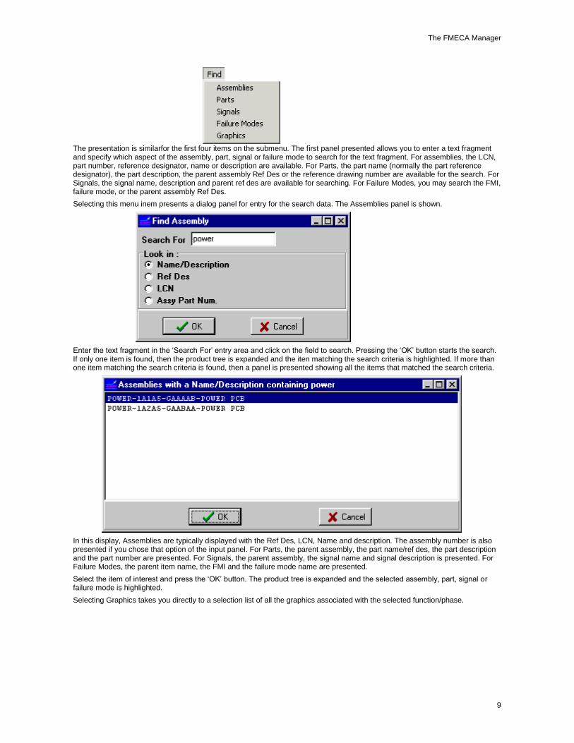
You can easily find any item on the product tree. The ‘Find’ selection of the main menu provides a submenu of the available search methods.
The FMECA Manager
9
The presentation is similarfor the first four items on the submenu. The first panel presented allows you to enter a text fragment and specify which aspect of the assembly, part, signal or failure mode to search for the text fragment. For assemblies, the LCN, part number, reference designator, name or description are available. For Parts, the part name (normally the part reference designator), the part description, the parent assembly Ref Des or the reference drawing number are available for the search. For Signals, the signal name, description and parent ref des are available for searching. For Failure Modes, you may search the FMI, failure mode, or the parent assembly Ref Des.
Selecting this menu inem presents a dialog panel for entry for the search data. The Assemblies panel is shown.
Enter the text fragment in the ‘Search For’ entry area and click on the field to search. Pressing the ‘OK’ button starts the search. If only one item is found, then the product tree is expanded and the iten matching the search criteria is highlighted. If more than one item matching the search criteria is found, then a panel is presented showing all the items that matched the search criteria.
In this display, Assemblies are typically displayed with the Ref Des, LCN, Name and description. The assembly number is also presented if you chose that option of the input panel. For Parts, the parent assembly, the part name/ref des, the part description and the part number are presented. For Signals, the parent assembly, the signal name and signal description is presented. For Failure Modes, the parent item name, the FMI and the failure mode name are presented.
Select the item of interest and press the ‘OK’ button. The product tree is expanded and the selected assembly, part, signal or failure mode is highlighted.
Selecting Graphics takes you directly to a selection list of all the graphics associated with the selected function/phase.

ASENT FMECA
10
You can now use the Find function to find the Assembly that has the graphic of interest attached.
Exiting the FMECA Manager
In addition to the traditional ways of closing a Windows application (using the close bar in the upper left corner or by pressing Alt-F4), ASENT provides two additional ways to exit the FMECA Manager:
Click the exit icon on the toolbar ( ).
or
From the File menu, select Exit.
You are returned to the Session Manager.
The Library Editor
Overview of the FMECA Library Editor
As you are working and find that an item is not in a library, you can add that item in the Library Editor and then have it available for your project.
From the Library Editor, you can add, edit, and delete items from these libraries:
Failure modes/effects
Signals
Severity levels
Probability groups
Detection Isolation Groups
Part types / failures
Detection categories, codes and default false alarm rates.
Component Mapping
Reliability Centered Maintenance (RCM) Tasks
Failure Categories are maintained from the data tab for any End Effect.
Once you bring up a library, it is active immediately. If you have created a new FMECA and use the common 1388 library, you will get defaults for severity levels.
The Library Editor also lets you:
The FMECA Manager
11
Use memos to add longer descriptions or other information.
Find specific records and each following occurrence with the ‘Find Record’ and ‘Find Next’ commands.
You can invoke commands by using the menu options, the toolbar icons, or by clicking with the right mouse to display a box of editing commands.
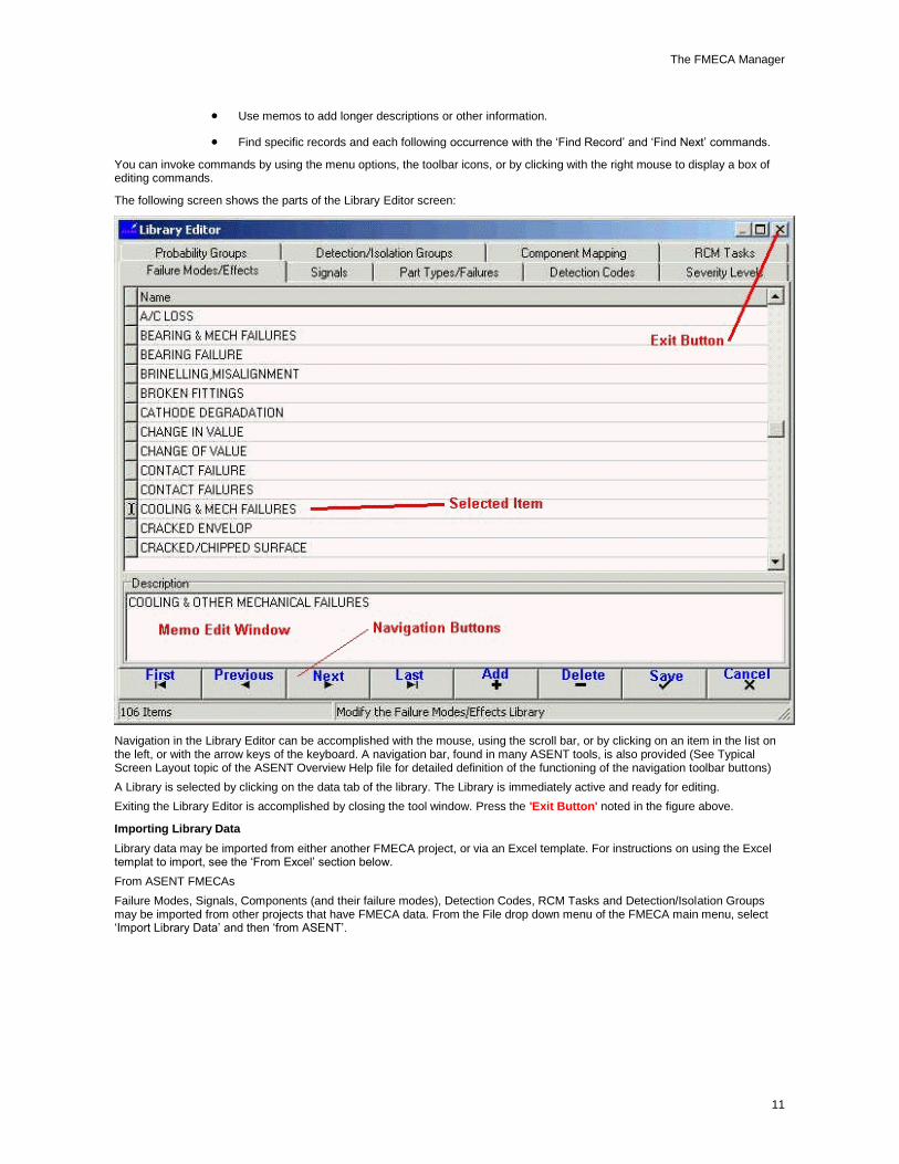
The following screen shows the parts of the Library Editor screen:
Navigation in the Library Editor can be accomplished with the mouse, using the scroll bar, or by clicking on an item in the list on the left, or with the arrow keys of the keyboard. A navigation bar, found in many ASENT tools, is also provided (See Typical Screen Layout topic of the ASENT Overview Help file for detailed definition of the functioning of the navigation toolbar buttons)
A Library is selected by clicking on the data tab of the library. The Library is immediately active and ready for editing.
Exiting the Library Editor is accomplished by closing the tool window. Press the 'Exit Button' noted in the figure above.
Importing Library Data
Library data may be imported from either another FMECA project, or via an Excel template. For instructions on using the Excel templat to import, see the ‘From Excel’ section below.
From ASENT FMECAs
Failure Modes, Signals, Components (and their failure modes), Detection Codes, RCM Tasks and Detection/Isolation Groups may be imported from other projects that have FMECA data. From the File drop down menu of the FMECA main menu, select ‘Import Library Data’ and then ‘from ASENT’.

ASENT FMECA
12
This brings up a panel to select the type of data want to import. Only one type of data may be imported at a time, but you can invoke the tool as many times as you want, picking and choosing different data from different projects.
Select the type of data you want to import and press the OK button. Next is presented a list of the FMECA projects on the server.
The project initially highlighted is the current project you are working on. Select the project you want to import data from and press the Ok button. The Cancel button aborts the import and takes you back to the FMECA Manager main screen.

The FMECA Manager
13
The list of the items on the selected project (in this case failure modes) is presented. This is a multiple selection grid, so CTRL+Click works, however Shift+Click does not (sorry!). To ease this shortcoming, a button is provided on the far right which toggles between ‘Select All’ and ‘Unselect All’ pressing the button selects all the items in the grid, then you just need to CTRL+Click on the items you DO NOT want to import.
Pressing the OK button imports the data and reports the progress on the diagnostics screen (which is where the list was before). If the import of an item is not performed, the reason is listed in the diagnostics window. The diagnostics window is a fully editable Rich Text window. The print button will sent the contents of this window to the default printer. The Save button will save the contents to a Rich Text (*.rtf) file which can be opened with most all word processors.
From Excel
Failure Modes and Signals may be imported from an Excel spreadsheet to populate the library. This could save a lot of time and effort, as many netlist tools offer Excel output, allowing the automated loading of signal names. The Import Tool is invoked from the File submenu of the FMECA Manager Main Menu. Select the ‘from Excel’ submenu item to invoke the tool.
Selecting the ‘Import Library Data’ menu item brings up the Library Import Tool.

ASENT FMECA
14
The tool will import the data from a single column of an Excel file. It will start on the line specified in the top input box and continue until it encounters an empty (or blank) cell in that column.
Select the type of data to import, fill in the data for the first data line and the column containing the data and press the ‘Start’ button. A ‘File Open’ dialog is presented.
Navigate to the directory containing the spreadsheet and select it. Press the Open button. The import begins.
During the import, a progress bar displays the progress of the import.
When the import is complete, the diagnostics from the import are displayed in the center of the panel.
The diagnostics will list any item that did not import, as well as the reason the item was not imported, most likely because already an item by the same name on the project (both signal names and failure mode names within a project must be unique).
From this screen you can Print or save the diagnostics to file, using the ‘Print’ and ‘Save’ button. You also have the option of modifying the font that the diagnostics report uses by selection the Options item of the main menu, ‘Font’ menu item and selecting the font, color and any style attributes you desire from the Font Dialog.

The FMECA Manager
15
When you are finished reviewing the report, return to the FMECA manager by Clicking the OK button or closing the Update tool (using either the ‘x’ in the upper right hand corner or the ‘File|Exit’ menu item.
Editing a Record
When you click on a library tab to display the contents of a library, that library is immediately active. For most fields, you merely click on a field and begin typing to make editing changes. You can also right-click with the mouse to display a menu of edit commands such as cut, copy, and paste. Some fields contain a selection button, that when clicked, displays a list of choices. The selection button does not display until you highlight the field and then click again. All memo fields are automatically displayed once the item is selected. To edit a memo, just click in the memo window and type or modify the existing text.
To edit a record:
1. Click on the field you want to change.
2. Type your changes.
3. Click on the icon before selecting another library or exiting the Library Editor.
To edit a record with a selection button:
1. Select the field and then click again to display the selection button (It is not always apparent if the field has a selection button).
2. Click on the selection button to display a list of choices.
3. Highlight your choice and it is placed in the field.
4. Click on the icon before selecting another library or exiting the Library Editor.
To edit a record using the Pop-Up Menu:
1. Highlight the text in the field and right-click with the mouse. Do not highlight the entire field.
2. Type your change or right-click with the mouse to display an edit menu.
3. Select the edit function. Note that cut and paste, and copy and paste are two-step functions and operate like all Windows edit functions.
4. Click on the icon before selecting another library or exiting the Library Editor.
If you select the entire field instead of only the text, a search menu displays instead of the edit menu when you right-click with the mouse. See Finding a Record.
Finding a Record
The Search command lets you find the first record with the defined criteria. You can also search the Memo field.
To find a record:
1 Highlight a field and right-click with the mouse.

ASENT FMECA
16
2. Click on the Search command.
3. Complete the Search screen:
Type the value you want to find.
Click in the Search Type box if you want the search to be case-sensitive.
Click the button for the type of match: Exact, Partial at beginning, or partial match anywhere.
Use the drop down box to select the search field.
4. Click on the ‘First’ button.
ASENT locates the record containing the search text and makes it the current record:
If you select only the text instead of highlighting the entire field, an edit menu displays instead of the search menu, when you right-click with the mouse. See Editing a Record in the Library Editor.
Finding Next Record
After defining a search using the Search command, you can keep searching to find the next occurrence of the search text. This assumes that you have already searched and found one match. See Finding a Record.
To find the next record:
1. With the previous search field highlighted, right-click with the mouse.
2. Click on the Search command.
3. On the Search screen, click on the ‘Next’ button.

The FMECA Manager
17
ASENT locates the next occurrence of the record and makes it the current record.
Editing the Component Mapping
The Component Mapping Library Tool lets you map components from the ASENT reliability tree to items in the 'Part Types/Failures' library, so that when the part is imported into a FMECA from a Reliability Manager product tree, the template failure modes are also added to the FMECA tree. The following capabilities are available after selecting the Component Mapping tab.
To Edit component maps:
1. Highlight the component type that you want to map to a different component. The first three fields are ASENT component types.
2. Click in the component field, and then click again to display the drop-down box.
3. Click on the drop down box to display a list of components.
4. Select the component that the part type will be mapped to.
5. Click on the icon to save your mapping.
To Delete component maps:
1. Click on a row in the in the mapping grid to select the row to be deleted. Click the right mouse button. The pop-up menu is presented:
2. Select ‘Delete’. A confirmation prompt will be presented.
3. Clicking the ‘Yes’ button on the confirmation prompt deletes the component map and the grid is refreshed.
To Add component maps:
1. Click the right mouse button. The pop-up menu is presented
2. Select ‘Add’ from the pop-up menu. A grid of part type/subtypes/styles without FMECA component maps is presented.

ASENT FMECA
18
3. Select the part type/subtypes/style from the left grid.
4. Select the FMECA component type from the right grid.
5. Press the ‘Ok’ button. The component map is added to the library editor grid and the grid is refreshed.
Editing the Detection Codes Library
The Detection Code Library Edit tool lets you edit, add, or delete detection categories and codes as well as add or edit the long description and default false alarm rate for a detection code. Only unused detection codes can be deleted.
To edit the Detection/Code library:
Click on the Detection/Codes tab. The Grids for the Category and Codes is displayed as well as the area to edit the long description.
Select a category and the Detection Code grid will display the Detection Codes of that category. You add a new Category by pressing the ‘+’ key while the highlight is in the Category grid. The Category names are limited to 255 characters.
Click on a detection code in the center grid to edit it or add a new detection code by pressing the ‘+’ key while the highlight is in the center grid. A name indicating whether the failure mode is detectable. It could be test code, or just a Yes/No to indicate whether you have detection. In some cases, it may not be applicable, and the code could be labeled N/A or TBD. Detection code names are limited to 255 characters. There is a column for each detection code for the entry of the default False Alarm Rate. Valid values for the False Alarm Rate are from 0 to 1, so something with a 15% false alarm rate would be entered as 0.15. The default false alarm rate is used to populate the False Alarm column in the testability grid when a new detection code is added. The user can then tailor the value as needed.
After changing the default false alarm rates, you can copy the new value to the existing testability data by selecting an item in the ‘Name’ column of the detection codes grid and clicking the right mouse button. A pop-up menu with a ‘Broadcast’ option is presented. This menu item has a submenu that will allow you select how many detection codes to update.

The FMECA Manager
19
Selecting a detection code displays the long description for the detection code. The detection code and long description data is saved when you press the save button or when you select another code or category.
The ‘Change Cat.’ button allows you to move a detection code from one category to another. If you move the last code out of a category, the category is also deleted and the data in the Category grid is refreshed.
Editing the Detection/Isolation Groups Library
The Detection/Isolation Groups Library Tool lets you add, modify, or delete Detection/Isolation groups. There is no limit to how many groups you can define. The titles show up on reports or spreadsheets when entering data.
To edit Detection/Isolation Groups:
1. Click on the Detection/Isolation Groups tab.
2. Complete the following fields:
Detectiion Group Enter a title to identify this detection group (for example, test) when it is displayed in edit screens and on reports. Some of the groups may be a visual inspection; for example, a LCD on the console. Or, the group could be identification of test points. The tests are designed to isolate down to a certain level. The title will appear in the FMECA tools and reports exactly as it appears in the list.
Isolation Group Enter a title to identify this isolation group when it is displayed in edit screens and on reports.
Isolation Type LRU or WRA, SRA, SRU, etc., depending on the services branch.
Iso Group Size1, 2, 3
Enter isolation group sizes (0-255) and their corresponding text (SRU, LRU, COMP) for all the levels you are isolating to. Up to three isolation group sizes can be defined for each detection/ isolation group. The size iso level may come from the customer in your specification.
Rel/FMECA Tree Specify whether the isolation list comes from the Reliability Manager product tree or the FMECA project tree by making a selection from the drop down menu.
Assy/Part
Specify whether the isolation group consists of assemblies or parts by making a selection from the drop down menu.
2. Click on the icon to save your edits.
Editing the Failure Modes/Effects Library
The Failure Modes Library Edit Tool lets you edit, add, or delete failure modes as well as adding or editing the memo that provides a long description for a failure mode. The memo may be output in the FMECA reports as well as in the LSAR export.

ASENT FMECA
20
Select the Failure Modes/Effects library by clicking on the Failure Modes/Effects tab.
This brings up a list of failure modes and effects.
An arrow indicates the current record.
To end the editing session, click on either the ‘Save’ or the ‘Cancel’ icon and then click on the ‘Close’ button to exit the Library Editor. You are returned to the FMECA Manager screen.
To edit a failure mode, highlight the field to be changed and type in the change. The definition for the fields in this library are:
Name Short description for the failure mode/effect that is limited to 255 characters.
Description The description is a memo, which has no size limitation, so this provides a means to enter detailed information or commentary concerning the failure mode or it’s application (or anything else, for that matter!).
Note: Only unused failure modes can be deleted. Also, changes will be posted when you move from one record to another, so if you accidentally change a failure mode name, click on the 'X' button to cancel the change before moving to another record.
Editing the Part Types/Failures Library
The Part Types/Failure Modes Library tool lets you edit, add or delete parts as well as add or edit the default failure modes associated with each part. The screen for this library is comprised of three panes. The upper left pane is for selecting the part.
The upper right pane displays the description for the selected part. Editing the part description is done by simply clicking in the right pane and typing in the new or changed text. The description will appear in the FMECA tools and reports exactly as it appears in the Part Library scroll box.
The third pane at the bottom of the screen displays the template (default) failure modes that will be added to the FMECA Manager product tree when the part is added. After adding a part, the part failure modes may be modified, deleted, or new failure modes added.
To edit the Part Types/Failures library:
1. Click on the Part Types/Failures tab.
2. Enter information for the following fields:
Name Short description for the Part Types/Failures. This is limited to 255 characters.
Description The description is a memo, and usually consists of a longer description for the name. No limit to the size of the memo. For example: If the part name is “RES-

The FMECA Manager
21
Composition”, the description might read, “Fixed Resistor, Metal Oxide, RN/RNC/RNR type, precision.”
FM In a split screen below the part type information, shows failure modes associated with the part type.
fm ratio In a split screen below the part type information, shows the percentage of the likelihood that the failure mode will be the cause of an actual failure of the part type.
3. The data is saved when you press the ‘Save’ button or when you select another part.
Editing the Probability Groups Library
The Probability Groups library lets you define or edit groups and the criticality numbers that make up the boundaries for each group. These groups are used in the Criticality Matrix report that plots probability of occurrence.
The FMECA Toolkit supports almost an unlimited amount of probability groups, but in most cases, you will only need about five. The boundaries must be in increasing probability from the bottom of the list to the top.
To edit Probability Groups:
1. Click on the Probability Groups tab.
2. Complete the following fields:
Rank The rank is in the form of 1, 2, 3 or A, B, C, etc., with the highest probability at the top of the list.
Description Describes the rank. For example, “Frequent,” “Reasonably Probable,” “Occasional,” or “Remote.” The description will appear in the FMECA tools and future reports exactly as it appears in the list.
Criticality Threshold Number
The minimum Criticality Number (in failures per million) of items which would fall in this rank.
3. The data is saved when you press the ‘Save’ button or when you select another rank.
Editing the RCM Tasks Library
The RCM Tasks Library Edit Tool lets you edit, add, or delete tasks used as part of Reliability Centered Maintenance as well as adding or editing the memo that provides you an opportunity to record a note or status statement that will be available whenever the task is referenced. The notes_status may be output in the FMECA RCM reports.
Select the RCM Tasks library by clicking on the RCM Tasks tab.

ASENT FMECA
22
This brings up a list of RCM Tasks.
An arrow indicates the current record.
To end the editing session, click on either the ‘Save’ or the ‘Cancel’ icon and then click on the ‘Close’ button to exit the Library Editor. You are returned to the FMECA Manager screen.
To edit a RCM task, highlight the field to be changed and type in the change. The definition for the fields in this library are:
Name Short description for the failure mode/effect that is limited to 255 characters.
Notes/Status This is a 255 character text field, so this provides a means to enter detailed information or commentary concerning the RCM Task or it’s status (or anything else, for that matter!).
Note: Only unused RCM Tasks can be deleted.
Editing the Severity Levels Library
The Severity Level Editor provides you with the capability to edit, add ,reorder or delete severity levels. Any level with a non-blank description is considered to be defined and available for use. Only severity levels that are not referenced in the FMECA can be deleted. Since severities are only associated with End Effects, checking usage is easily done by clicking on the Failure Modes bucket under the System node.
To Add Severity Levels
Severity Levels are added by placing the selector arrow at the location where you want the new severity level inserted and pressing the Insert( '+') button on the navigator bar at the bottom of the window. Then type in your severity level, up to 3 characters, like 1B or 1- or ABC the click on the description field and enter a name for the new severity.When you are satisfied with the presentation of the new severity, press the 'Save' button like
To edit severity levels:

The FMECA Manager
23
1. Click on the Severity Levels tab.
2. Complete the following fields:
Severity Level A combination of numbers and letters (up to 10 characters) indicating the priority of the severity. Example: 1 for catastrophic !2 for mission loss, 2B for possible mission loss, etc .
Name Name of the severity, such as Catastrophic, Mission Loss, etc
Description Provides a memo to describe any aspect of the severity level that you desire..
3. The data is saved when you press the ‘Save’ button or when you select another severity level.
4. The arrows on the right hand side will move the selected severity (the one with the arrow on the left) up or down in the secuence of priorities. The ASENT FMECA tools consider the first severity to be the most severe and decreasing severity as the list is traversed downward to the least at the bottom.
Editing the Signals Library
The Signals Library Edit Tool lets you edit, add, or delete signals as well as edit the description of a signal. The description provides an opportunity to provide a more detailed explanation of the signal and its function in the system. Only unused signals can be deleted.
To edit the signals library:
1. Click on the Signals tab.
2. Enter information for the following fields:

ASENT FMECA
24
Name Short description for the name of the signal. For example, 5V POWER, FILTER OFF, FILTER ON, POSITION ADJUST, or RESET. The name is limited to 255 characters.
Description The description is a memo, which has no size limitation, so this provides a means to enter detailed information or commentary concerning the signal.
3. Click on the icon to save your edits.
Working with the Product Tree
Working with the Project Tree
When you invoke the FMECA Manager, the system node for your current function/phase displays. Click on the plus sign to expand the product tree. To select a node, click on it to make it active. When a node is active, you can right-click with the mouse to bring up a menu of command options that can be performed on that node.
In the FMECA Manager, there are no boards. Boards are treated as assemblies. Each system and assembly node contains an ‘FMs’ node, a signals node, and a parts bucket. The parts bucket may have parts, and these parts each have an ‘FMs’ node. A FMECA can be run with empty parts and signals buckets on just an assembly.
Use the keypad to expand and close the project tree from a selected location. Highlight a system or assembly node and press the plus sign (+) to expand the tree or press the minus key (-) to close the tree.
If you click on the plus sign next to a node ( ), a list of the individual components for that node displays. You can then click on the individual component to view and edit specific component data.
The FMECA Product Tree functions are similar to those in the Reliability Manager. You can add, move, and copy failure modes, signals, and parts.
See:
FMECA Project Tree: The System Node
FMECA Project Tree: Assembly Nodes
FMECA Project Tree: Failure Mode Nodes
FMECA Project Tree: Failure Modes for Parts
FMECA Project Tree: The System Node
From the system node, you can add subassemblies, calculate criticality, initialize and calculate testability, import a subtree, invoke the LCN editor, refresh the product tree structure display, roll up failure mode ratios, generate reports for the entire FMECA structure, and update failure rates from the reliability side.
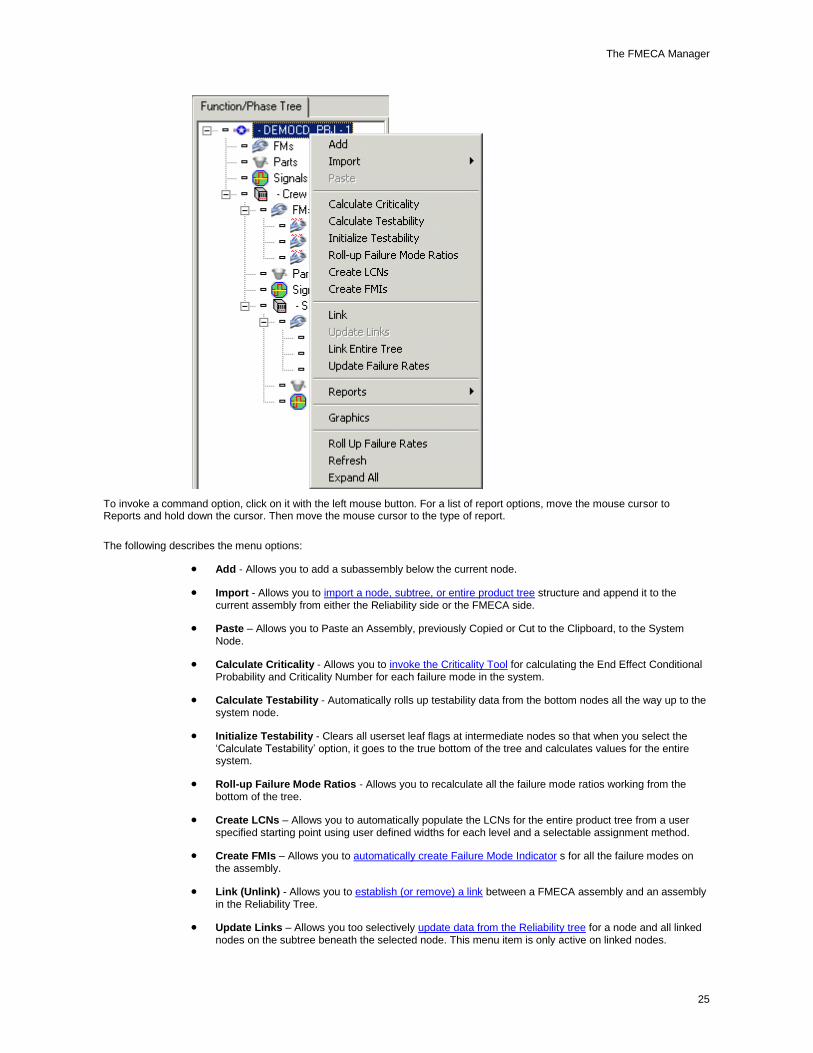
To invoke a command option, click on it with the left mouse button. For a list of report options, move the mouse cursor to Reports and hold down the cursor. Then move the mouse cursor to the type of report in the list that displays.
When you select the system node and right-click on the mouse, the following menu options display:
The FMECA Manager
25
To invoke a command option, click on it with the left mouse button. For a list of report options, move the mouse cursor to Reports and hold down the cursor. Then move the mouse cursor to the type of report.
The following describes the menu options:
Add - Allows you to add a subassembly below the current node.
Import - Allows you to import a node, subtree, or entire product tree structure and append it to the current assembly from either the Reliability side or the FMECA side.
Paste – Allows you to Paste an Assembly, previously Copied or Cut to the Clipboard, to the System Node.
Calculate Criticality - Allows you to invoke the Criticality Tool for calculating the End Effect Conditional Probability and Criticality Number for each failure mode in the system.
Calculate Testability - Automatically rolls up testability data from the bottom nodes all the way up to the system node.
Initialize Testability - Clears all userset leaf flags at intermediate nodes so that when you select the ‘Calculate Testability’ option, it goes to the true bottom of the tree and calculates values for the entire system.
Roll-up Failure Mode Ratios - Allows you to recalculate all the failure mode ratios working from the bottom of the tree.
Create LCNs – Allows you to automatically populate the LCNs for the entire product tree from a user specified starting point using user defined widths for each level and a selectable assignment method.
Create FMIs – Allows you to automatically create Failure Mode Indicator s for all the failure modes on the assembly.
Link (Unlink) - Allows you to establish (or remove) a link between a FMECA assembly and an assembly in the Reliability Tree.
Update Links – Allows you too selectively update data from the Reliability tree for a node and all linked nodes on the subtree beneath the selected node. This menu item is only active on linked nodes.

ASENT FMECA
26
Link Entire Tree – Allows you to rapidly re-establish links after major modifications of the Reilability Product Tree. Goes through the entire FMECA tree and links the FMECA assemblies to their counterparts in the reliability tree by matching the features of the assemblies (name, reference designator, part number, relative indenture). Also re-establishes part links based on a similar approach and including the reference designator of the linked parts.
Update Failure Rates - Invoke the Update Failure Rates Tool that allows you to update FMECA failure rates with the either the current ASENT operations failure rates, the storage & dormancy failure rates, or even specify a user defined to update the failure rates for the project. See Update Failure Rates.
Reports - Allows you to generate all the reports listed in the Generating Reports section.:
Graphics – Store graphics (pictures, schematics, assembly drawings, sketches, Excel Worksheets, PDF files, video, etc) with an assembly. View the stored graphics or export them to a file.
Roll Up Failure Rates – The failure rates in the product tree will normally automatically roll up and re-sum, but we have come across a couple of situations, such as after imports of subtrees, where the failure rate of a an assembly will be blank. Selecting the assembly and selecting this menu option will sum up the failure rate of all the children assemblies, parts and signals. If the failure rate remains blank, then one of the children items also has a blank failure rate, so expand the assembly and inspect the children.
Refresh - Redisplay the project tree with the latest changes.
Expand/Collapse All – Selecting this menu item will completely expand the tree with a single mouse click, exposing all the items down to the failure mode (lowest) level. If the tree is sizable, this can take a minute or two. After the tree is expanded the caption on the menu item is changed to ‘Collapse All’ and selecting this option will collapse the entire tree, displaying only the system node, in a signle mouse click.
The Assembly Data Tab
When you select the system node, Assembly Data displays on the right side of the screen. The following tabs become available, where you can further describe the current FMECA structure:
Assembly tab - Allows you to enter general information for the system node. For the system node, the Full RD defaults to 1, quantity defaults to 1, and duty cycle defaults to 1.
Equipment List tab - Allows you to list equipment that is not critical for mission success. Used for Logistics reports (LSAR).
Functional Description tab - Allows you to enter a more detailed description about this phase of the project.
Phase tab - Allows you to enter the function, phase, and mission time.
RCM tab – Summarizes Reliability Centered Maintenance performed to date. Allows you to conduct or modify the analysis. See the section on Performing RCM Analysis for details.
You can enter or modify the data in these fields. Just click on the tab and then in the field and enter the information you want. Click on ‘Save’ to save the new data.
FMECA Project Tree: Assembly Nodes
In the FMECA Manager, both subassemblies and boards are considered assemblies.
From an assembly, you can add other assemblies, calculate failure rates, import a subtree, invoke the LCN editor, and generate reports for the assembly.
When you select an assembly node and right-click on the mouse, the following menu options display:

The FMECA Manager
27
To select a command option, click on the option. For a list of report options, move the mouse cursor to Reports and hold down the cursor. Then move the mouse cursor to the type of report in the list that displays.
The following describes the menu options:
Add - Allows you to add an assembly below the current node.
Delete - Allows you to delete the current assembly. This option is not available on the system node. If you want to delete the system node, you must do this in the Session Manager.
Import - Allows you to import a subtree from another project and append it to the current assembly.
Copy – Copies an assembly and associated subtree to the Clipboard.
Paste – Pastes any assembly previously copied to the clipboard to the selected assembly.
Create LCNs - Allows you to automatically populate the LCNs for the selected assembly and branch of the tree below the selected assembly from a user specified starting point using user defined widths for each level and a selectable assignment method.
Create FMIs – Allows you to automatically create Failure Mode Indicators for all the failure modes on the assembly.
Link Node - Allows you to establish (or remove) a link between a FMECA assembly and an assembly or parts on an assembly in the Reliability Tree.
Update Links – Allows you too selectively update data from the Reliability tree for a node and all linked nodes on the subtree beneath the selected node. This menu item is only active on FMECA Assemblies that are linked to Assemblies in the Reliability Tree..
Link Subtree – Allows you to rapidly re-establish links after major modifications of the Reilability Product Tree. Goes through the subtree of the selected FMECA node and links the FMECA assemblies to their counterparts in the reliability tree by matching the features of the assemblies (name, reference designator, part number, relative indenture). Also re-establishes part links based on a similar approach and including the reference designator of the linked parts.
Update Failure Rates - Invokes the Update Failure Rates Tool that allows you to update FMECA failure rates with values from the current ASENT operationsal failure rates, the storage & dormancy failure rates or values from a user defined field for the project. See Update Failure Rates
Reports - Allows you to generate the following reports:
End Effect Criticality Numbers
End Effects to Causes (Trace Report)

ASENT FMECA
28
FMEA (1629) Report
FMECA Report
Custom Crystal FMECA Report – Presently populated by the last format requested by BAE systems, but immediately replaceable by a format that you can specify.
Custom Excel FMECA Report – Presently populated by the last format requested by Boeing, but immediately replaceable by a format that you can specify.
Item Criticality Matrix Report
Critical Failure Modes Report
Critical Items Report
Metric Reports (These consist of a Failure Mode Count Report and a Detection Code Count Report)
Testability Reports (These consist of the Test Coverage Summary, the Testability Spreadsheet, the Assy FM Test Report, the Isolation List Overview, the Part Link List Report and the BIT Design Impact Report.)
User Defined Report
Graphics – Store graphics (pictures, schematics, assembly drawings, sketches, etc) with an assembly. View the stored graphics or export them to a file.
Roll Up Failure Rates – The failure rates in the product tree will normally automatically roll up and re-sum, but we have come across a couple of situations, such as after imports of subtrees, where the failure rate of a an assembly will be blank. Selecting the assembly and selecting this menu option will sum up the failure rate of all the children assemblies, parts and signals. If the failure rate remains blank, then one of the children items also has a blank failure rate, so expand the assembly and inspect the children.
Refresh - Redisplay the project tree with the latest changes.
The Assembly Data Tab:
When you select an assembly node, the Assembly Data tab displays on the right side of the screen. The following tabs become available, where you can further describe the current assembly:
Assembly tab - Allows you to enter general information for the assembly node. This includes the ‘Assy Type’ which is used to build the Isolation Lists when conducting Testability Analysis. The ‘Assy Type’ drop down list is comprised of the types you have typed in on previous assemblies, so initially it will start out empty. Close the drop down and enter the assembly type in the display field. When you press ‘Save’, the assembly type you entered will be added to the drop down list.

The FMECA Manager
29
Equipment List tab - Allows you to list equipment that is not critical for mission success. Used for Logistical reports (LSAR).
Functional Description tab - Allows you to enter a more detailed description about the assembly.
RCM tab – Summarizes Reliability Centered Maintenance performed to date. Allows you to conduct or modify the analysis. See the section on Performing RCM Analysis for details.
You can enter or modify the data in these fields. Just click in the field and enter the information you want. Then click on Save to save the new information.
FMECA Project Tree: Parts & Signals
The Signals Node
From the Signals node, you can add signals to the system or assembly node. When you highlight a Signals node, you get a spreadsheet listing the name, description, quantity, failure rate, and duty cycle of the signal.
When you select a Signals node and right-click on the mouse, the following menu options display:
The following describes the menu options:
Add - Allows you to add a signal.
Delete Group - Allows you to select a number of signals and delete them in one operation. signals are selected using the standard windows Ctrl+Click to toggle the selection highlight. The Click/Shift-Click can also be used to identify a span of signals. Selecting 'OK' after selecting the signals, deletes the selected signals. Pressing 'Cancel' aborts the deletion process.
Refresh - Redisplay the project tree with the latest changes.
To invoke a command option, click on it with the left mouse button.
The Signals List Tab for the Signals Node
When you select a Signals node, the Signals List displays on the right side of the screen. The following tab becomes available to enter the information for the signal.
Signals tab - Allows you to enter signal information.
You can enter or modify the data in these fields. Just click on the tab and then in the field and enter the information you want. Click on ‘Save’ to save the new information. For this grid the Resize Hot Spot is very convenient. Click on the Resize Hot Spot and you have access to all the grid fields without horizontal scrolling.
An Individual Signal (the Signal Node)
When you select an individual signal and then right-click with the mouse, the following menu displays:

ASENT FMECA
30
You can Delete the signal, Link the Signal to parts on the parent assembly (provided the parent assembly is linked), Unlink the signal, produce reports for the selected signal or refresh the tree at this level, re-reading the failure modes and failure mode data.
Signal Data Tab
When you select an individual signal in the product tree, the Signal Data Tabs display on the right side of the screen.
The following is a brief desription of the information for a signal:
Name: this is the name of the signal, such as is shown on a netlist.
Description: this is the description of the signal, selected from the signal library.
Quantity: the quantity of signals that the item represents, typically 1, but for things like data buses, it might be easier for you to summarize all the bits of a parallel data bus on one signal with the quantity of 16 or 32.
Failure rate: the failure rate of One of the signals represented by the node.
Duty Cycle: Value from zero to one. Used to determine the contribution of the signal node to the parent assembly.
Example Calculation: A signal node, with failure rate set to 1.0, quantity set to 4 and duty cycle set to 0.75 will contribute a failure rate of 3 (1 * 4 * 0.75) to the parent assembly.
Parts Node (or Parts Bucket)
When you select a Parts bucket, (click on the word “Parts,”) you can add components to your part list for the node. If you click on the plus sign next to the Parts bucket, the parts list expands to show each component in the node.
Select the Parts bucket and right-click with the mouse. The following menu displays:
Select the option by clicking with the mouse.
The following describes the menu options:
Add - Allows you to add a part to the project structure. Here, you specify the part name (reference designator) and select the type of part by selecting one of the part description choices in the description

The FMECA Manager
31
field. This selection is used to populate the failure modes and failure mode ratios from the FMECA Part Type/Failures library.
Import Rel. Tree Parts - Brings in the parts from the Reliability Tree for the item it is linked to. Requires that the item in the FMECA is linked to an item in the Reliability tree. If parts already exist on the FMECA item they will be overwritten by the import process.
Delete Group - Allows you to delete many of the parts in the bucket with one command.
Reports | Part FM Data Template - Creates an Excel report template that is used by the Update Part FM Data option. This report uses the ASENT\Data\FMECA_Export_PartFMData_Template.xls and fills in any data that is available. At a minimum, this report normally outputs the part name (reference designator), along with the failure mode names, so that the user can fill in additional data in Excel and bulk load it.
Update Part FM Data - This utility takes the template created in the above report and bulk loads this data for part failure modes. This can be particularly useful when performing a piece-part level FMECA, as it allows the user to leverage copy/paste and other editing features in Excel and bulk load this information into ASENT.
Refresh - Redisplay the project tree with the latest changes.
Parts List Tab:
When you select a Parts bucket, a Parts List tab displays to the right.
Part tab - Allows you to display and edit information about the part structure. A spreadsheet displays with the fields for name, description, full-rd, quantity, failure rate, duty cycle, and ref drawing number. For this grid the Resize Hot Spot is very convenient.
An Individual Component (the Part Node)
When you select an individual component and then right-click with the mouse, the following menu displays:
You can delete the component or refresh the project tree.
Delete - Allows you to delete a component from the FMECA structure.
Refresh - Redisplay the project tree with the latest changes.
When you select a part, the part information displays to the right.
Part Data Tab - Allows you to display and edit information about the part structure.
Functional Description Tab - Allows you to add additional information about the part.
Part Data Tab
When you select an individual component in the product tree, the Parts Data Tabs display on the right side of the screen.

ASENT FMECA
32
The following is a brief desription of the information for a part:
Name: this is normally the abbreviated reference designator (or designators if the quantity is more than one) of the part/parts. Such as
‘Q1’ or perhaps ‘C1-15, 20,27-34’ for a group of bypass capacitors.
Description: this is the part type, selected from the part typers library.
Parent’s Full RD: this is the reference designato of the assembly on which the part is mounted. For physical FMECA’s this will be the same for all the parts on an assembly, but for functional FMECAs, where the FMECA assebmly is a function, it can vary from part to
part and will reflect the reference desigantor of the assembly of the individual part.
Quantity: the quantity of parts that the item represents, typically 1, but it might be easier with some parts (like decoupling capacitors
or pull up resistors) for you to summarize all parts of a group with one part with the quantity of the parts beign represented.
Failure rate: the failure rate of One of the parts represented by the node.
Duty Cycle: Value from zero to one. Used to determine the contribution of the part node to the parent assembly. The duty cycle is
applied to the failure rate as it is rolled up to the parent assembly. For example, if the failure rate of the part is 1.0 and the duty cycle is 0.5, then a failure rate of 0.5 will be rolled up to the parent assembly.
Ref Drawing Number: This is the part number of the part.
Isolatable:
LCN: The logistics control number of the part. Not typically used for piece parts, but for purchased assemblies, like EMI filters, it may
be useful. Should not be used if the quantity is greater than 1, as it will cause confusion in the LSAR.
Example Calculation: A part node, representing 18 decoupling capacitors, with failure rate set to 0.10, quantity set to 18 and duty cycle set to 0.75 will contribute a failure rate of 1.35 (0.10 * 18 * 0.75) to the parent assembly.
FMECA Project Tree: Failure Mode Nodes
Failure Modes at the System Level
From the Failure Mode (FM) bucket under the system node, you can add End Effects for the FMECA. When you highlight a failure mode node, you get a spreadsheet listing the failure mode, fm ratio, and severity level.
When you select the FM bucket of the system node and right-click on the mouse, the following menu options display:
To invoke a command option, click on it with the left mouse button.
Add - Allows you to add a failure mode that applies to the entire FMECA structure.
Delete Group - Allows you to select a number of failure modes and delete them in one operation. The failure modes are selected using the standard windows Ctrl+Click to toggle the selection highlight. The

The FMECA Manager
33
Click/Shift-Click can also be used to identify a span of failure modes. Selecting 'OK' after selecting the failure modes, deletes the selected failure modes. Pressing 'Cancel' aborts the deletion process.
Create FMIs – Allows you to automatically create Failure Mode Indicators for all the failure modes in the bucket.
Refresh - Redisplay the project tree with the latest changes.
The Data Tab for the FM Bucket at the System Level
When you select the FM bucket under the system node, one tab displays on the right side of the screen. The following tab becomes available to enter the End Effects for the FMECA.
End Effects tab - Allows you to enter end effects for the FMECA and assign severity levels. The Failure Mode Indicator (FMI) sorts the Failure Modes. After changing FMIs, to resort and redisplay the grid, click the right Mouse Button anywhere inside the grid. The ‘Refresh’ pop-up menu item is displayed.
Click on the ‘Refresh’ item and the grid is redisplayed in the new sort order. The Failure Mode items in the tree are also sorted by FMI and will shift as you change the data in the grid.
You can enter or modify the data in these fields. Just click on the tab and then in the field and enter the information you want. Click on ‘Save’ to save the new information.
Failure Modes at the Assembly Node Level
From the Failure Mode (FM) bucket under the assembly node, you can add failure modes for the assembly. When you highlight a failure mode bucket, you get a spreadsheet listing the failure mode, fm ratio, and local effect.
When you select the a FM bucket at the assembly node and right-click on the mouse, the following menu options display:
To invoke a command option, click on it with the left mouse button.
Add - Allows you to add a failure mode.

ASENT FMECA
34
Delete Group - Allows you to select a number of failure modes and delete them in one operation. The failure modes are selected using the standard windows Ctrl+Click to toggle the selection highlight. The Click/Shift-Click can also be used to identify a span of failure modes. Selecting 'OK' after selecting the failure modes, deletes the selected failure modes. Pressing 'Cancel' aborts the deletion process.
Create FMIs – Allows you to automatically create Failure Mode Indicators for all the failure modes in the bucket.
Refresh - Redisplay the project tree with the latest changes.
The Data Tab for the FM Bucket at the Assembly Node Level
When you select the FM bucket for an assembly, the Failure Modes List displays on the right side of the screen. The following tab becomes available:
FMs tab - Allows you to enter information about the failure modes. The Failure Mode Indicator (FMI) sorts the Failure Modes. After changing FMIs, to resort and redisplay the grid, click the right Mouse Button anywhere inside the grid. The ‘Refresh’ pop-up menu item is displayed.
Click on the ‘Refresh’ item and the grid is redisplayed in the new sort order. The Failure Mode items in the tree are also sorted by FMI and will shift as you change the data in the grid.
You can enter or modify the data in these fields. Just click on the tab and then in the field and enter the information you want. Click on ‘Save’ to save the new information.
An Individual Failure Mode
When you select an individual failure mode and then right-click with the mouse, the following menu displays:
The following describes the menu options:
Delete - Allows you to delete the failure mode from the FMECA structure.
Refresh - Redisplay the project tree with the latest changes.
Reports – Generate the Isolation List Overview for the selected failure mode (See Isolation List Overview Report).
Failure Mode Data Tabs
When you select an individual failure mode in the project tree, the Failure Mode Data tabs display on the right side of the screen.

The FMECA Manager
35
The following tabs display under Failure Mode Data:
FM - Modify the failure mode, local effect, and failure mode ratio for the current item. You can also add
new failure modes and effects to the library by pressing the ‘new’ ( ) button and typing in the name and description of the new library entry.
Next Effects - Allows you to display the parent failure modes and a list of the next effects. Parent failure modes are listed in the left window and the next effects on the right. This is where you define next effects for the given failure mode.
Causes - Allows you to display the opposite of the next effect - the cause. Lists the failure mode name and the part, signal, or assembly causing the failure. The source node is the part, signal, or assembly.
Detect Method - Allows you to enter text about the method used to detect the failure mode.
Remarks/Actions - Allows you to enter an additional remark for the failure mode as well as all the Mishap Risk Analysis data.
Maintenance Remarks - Allows you to enter additional maintenance remarks for the failure mode.
Provision - Allows you to enter compensating provisions, for example, redundancy in the case of a critical item.
Testability - Allows you to list the groups and the detection method you will use in your testability calculations.
End Effects - Allows you to quickly see all the end effects, severities and conditional probabilities for the selected failure mode. Simply display this tab and the information is there along with a note as to the currency of the end effect data.
Adding an Assembly
To add an assembly:
1. On the Function/Phase Tree, highlight the node where the assembly is to be added.
2. Click once with the right mouse button. The command menu displays:

ASENT FMECA
36
3. Click once on Add. The Assembly tab on the right displays with blank fields for entering information about the new assembly and the ‘Save’ and ‘Cancel’ buttons become active.
4. Type the name of the assembly. Press the tab key to move to each new field.
5. Enter a generic description and press tab.
6. Enter the full reference designator and press tab.
7. Enter the quantity. Only integers are allowed. Press tab.
8. Enter the failure rate if this assembly has a set failure rate. Otherwise, leave it blank. Press the tab key.
9. Enter the duty cycle. Typically, this will be a ratio between 0 and 1. This value is used determine the failure rate contribution to the parent assembly. Press the tab key.
10. Enter the assembly part number and press the tab key.
11. Enter the Logistics Control Number (LCN) and press the tab key.
12. If the assembly is part of the minimum equipment list, click in the check box.
13. The ‘Isolatable’ check box is checked by default, if the unit is not isolatable, uncheck the checkbox.

The FMECA Manager
37
14. The ‘Assy Type’ field is used in Testability Analysis to identify the assemblies which are isolation candidates for each detection group. This field is composed of a editable entry field and a drop down list of types previously entered in on the project. Either type in the assembly type (WRA, SRA, LUR, etc) or select it from the drop down list if is available. The data you type in will be added to the drop down list when you press ‘Save’.
15. Click on ‘Save’.
The assembly is added to the function phase tree.
Editing an Assembly
You can edit the information for an assembly.
To edit:
1. Select the assembly to edit.
The information for the Assembly displays under Assembly tab to the right.
2. Make your changes.
3. Click the ‘Save’ button.
Assembly Graphics
The ‘Graphics’ menu item provides you the capability to associate graphics, such as pictures, schematics, assembly drawings, sketches, etc with an assembly. Selecting this menu item invokes the ASENT Graphics Viewer. Links to this tool are provides from the Reliability Manager, FMECA Manage and the Maintainability Manager. The detailed operation of the viewer is presented in the Help File for the ASENT Graphics Viewer.
Linking and Unlinking
Linking assemblies and signals on the FMECA tree to the Reliability Tree can either be done individually, on a node by node basis, or where the trees and assemblies are very similar, ‘Link Tree’ and ‘Link Subtree’ options of the System and Assembly menus can provide a significant productivity boost by automatically linking the FMECA and Reliability assemblies based on matching features (name, relaitve indenture, name, assembly part number, reference designator and LCN). Selecting either of these options resulats in the mouse icon changing to the SQL hourglass while the matching is performed. When the process is complete, the selected node is collapsed and redrawn to show the icons for the linked assemblies where the matches were made.
To individually link a node, select the ‘Link Node’ from the pop up menu.On the System node, the Link Node is a simple option, but for lower level assemblies and signals on linked assemblies, the ‘Link Node’ menu item displays a submenu with 4 items:
Linking to parts is a two step process. The first step in the process is linking to the assembly on the Reliability Tree that has the parts of interest. Clicking on either ‘Assembly’ or ‘Parts’ brings up the Tree Panel with the Reliability Tree. Select the node in the Reliability Tree.

ASENT FMECA
38
Expand the tree unitl the assembly you want to link is displayed. Select that assembly and press the ‘OK’ button.
If Assembly was selected, the FMECA tree is redisplayed with the selected node collapsed (if it was previously expanded) now showing the symbol for a linked assembly (see the list of icons in the Icons & Toolbar topic). The Assembly tab will display a message indicating the linkage.
If ‘Parts’ were selected, a panel is presented listing the parts on the selected assembly in the reliability tree.
Select the parts on the left hand side and press the top arrow to add to the list of linked parts. Select a part in the right side and use the bottom arrow to remove a part from the list of linked parts. The traditional Windows Ctrl+Click and Shift+Click selection methods work in both windows allowing you to move several parts with one click of the arrow.
When a part is initially selected, the FR Ratio column will initially be blank. It will be filled in with the default value (1.00) when you press ‘OK’. You only need to put in a value if the ratio of the failure rate to use in this application is less than 1. This allows you to allocate the failure rate of a part (such as a microprocessor) to many different signals or functions and without having the failure rate of the part show up in your FMECA tree more than once. Press ‘OK’ when you are complete.
The FMECA will be checked and all the linked parts which have a failure rate ratio greater than one on the selected node will be identified.
If there are no parts exceeding 1, or you pressed ‘OK’ on the previous prompt, the FMECA tree collapses on the selected node and the new icon for a linked item is shown. A message indicating that the Assembly is linked to parts is displayed.
If you want to change the part linkage at a later time, selecting ‘Link Node|Parts’ will bring up the same panel with your current selections and you can change the parts or the FR Ratios of the linkage.
Linking Signals to parts is also a two step process. The fist step is linking the parent Assembly to either parts or an assembly in the Reliability Tree. The signal node ‘Link’ item will then become active, and when selected will have two items in the submenu.

The FMECA Manager
39
Selecting ‘Add/Edit’ brings up the part selection panel for the list of parts on the Reliability Tree Assembly that the parent of the Signal is linked to.
Unlinking is done by simply selecting the ‘Unlink’ item from the submenu. A confirmation prompt is presented. Pressing the ‘Yes’ button completes the unlink and the FMECA tree is collapsed to the selected node and the new ‘Unlinked’ icon is shown. When switching between being linked to an assembly or being linked to a part, it is necessary to first ‘Unlink’ to remove the old links.
Updating Links
Selecting this menu item of the Assembly or System menus displays a panel of check boxes of data which can be updated by linkage.
Check the items of data you want updated and press ‘OK’. The data for the linked assembly and any assemblies linked to assemblies on the Reliability Tree on the subtree below the selected assembly will be updated with data from the Reliability Tree. Assemblies that are linked to parts are not updated, as these are typically functional blocks, and the desriptive data input by the user would be overwritten by assembly information.
Copying an Assembly
An assembly can be copied to a new location using either of two methods. You can use the Drag & Drop method with the mouse or you can use the Copy/Paste menu items on the Assembly Node drop down menu.
To copy an assembly using Drag & Drop:
1. Select the assembly to be copied.
2. Hold down the Ctrl key and the left mouse button and drag the assembly to the new parent node where you want it to be copied.
The assembly is copied and displays under the new parent node.
The following figure shows the 'Sound' assembly in the process of being copied to the 'Keyboard' assembly.
To copy an Assembly Using Copy/Paste:
1. Select the assembly to be copied. Right click on the mouse to open the drop down menu.

ASENT FMECA
40
2. Select Copy. Notice that the right side of the button bar now has a green label identifying that the assembly clipboard is now populated, and what assembly is now in the clipboard
.
3. Select the Assembly you want to paste the copy on, that is the parent assembly for the new assembly. Right click on the new paren assembly to bring up the drop down menu. Notice now that the Paste option is available. It will be available whenever the Assembly Clipboard label is visible. Select Paste. The new assembly is added to the product tree with all of it's failure modes and/or children assemblies/signals and parts.
(Note: double clicking on the Assembly Clipboard label clears the clipboard and the label. Placing your mouse over the clipboard label for about 5 seconds will give you this same hint.)
Moving an Assembly
An assembly can be moved to a new location using either one of two methods, depending on which is more convenient at the time. The two methods are: Drag & Drop and Copy/Paste/Delete.
To move an assembly using Drag & Drop::
1. Select the assembly to be moved.
2. Hold down the left mouse button and drag the assembly to the new parent node.
You will be asked to confirm the move.
3. Click Yes to confirm.
The assembly displays under the parent node.
To move an assembly using Copy/Paste/Delete:
1. Select the assembly to be moved.
2. Right Click on the assembly to open the drop down menu.
3. Select 'Copy' from the dropdown menu. Notice that the Assembly Clipboard label now contains the name of the assembly you just selected.
4. Move to the assembly that will be the new parent to the new node.
5. Right click to open the drop down menu.
6. Select 'Paste'.
7. Return to the assembly to be moved and right click to open the drop down menu.
8. Select 'Delete' Do not delete the original assembly until after all the Pastes you desire are made, as deleting the assembly also clears out the assembly clipboard if it contains the selected node.
Deleting an Assembly
To delete an assembly:
1. Select the assembly to be deleted.

The FMECA Manager
41
2. Click once on the right mouse button.
3. Select Delete.
A window displays asking you to confirm the delete.
4. Click on Yes.
The assembly is deleted.
Importing Subtrees into FMECA
You can import subtrees, from a Reliability Manager product tree, another FMECA product tree or using an Excel template (FMECA Import.xls), furnished as part of the installation and placed in the Data subdirectory of your Asent installation. All projects on the workstation have reliability trees, but only projects which have FMECA data will have FMECA trees.
Importing a reliability product tree brings in a tree structure from the Reliability Manager. You may want to import a reliability subtree if you are just setting up the FMECA structure or you are only interested in performing a FMECA on your hardware.
Importing a FMECA tree has the advantage of copying in failure modes, next higher effects, and signals, and possibly functional blocks if they have been defined in the FMECA that you are importing.
Importing a product tree from Excel allows you to easily transition from another manufacturer’s FMECA toolkit, and creates library entries for the Failure Modes during the import. Severities and Criticalities should be defined prior to importing as these are used during the import.
Once you select the subtree, the tool begins to read the tree. If the reliability tree contains parts, you will be queried as to whether to import parts.
The import is only intended for the initial population of an assembly, subtree or product tree. Be very cautious if you are using it to update an existing FMECA Tree as any previously entered RCM, Safety, Graphics and Testability data associated with the assembly or failure modes updated by the import will be lost after the import.
Importing a Reliability Tree Structure
To import a subtree for a reliability tree product structure:
1. Highlight the assembly where the imported subtree is to be added.
1. Right click with the mouse and select the Import menu item, and the the ‘from Asent’ submenu item.

ASENT FMECA
42
3. Select the Reliability option:
4. Click OK. A list of projects displays.
5. Select the project that has the subtree you want to import.
6. Click on the plus signs to expand the project tree until you display the correct assembly or board.
7. Highlight the assembly or board and click OK.
8. Click Yes if you want to import parts.
9. Click ‘Yes’ if you want to create default failure modes for the parts. Selecting Yes brings in the failure modes from the part types/failures that this project uses.

The FMECA Manager
43
ASENT completes the import and displays the imported assembly below the node you selected. If the import was from the Reliability Tree of the parent project of the FMECA, then the assembly nodes will be imported as linked. Otherwise they will be Unlinked
Importing a Subtree from another FMECA Project
1. Highlight the assembly where the imported subtree is to be added.
2. Right click with the mouse and select the Import command, then the ‘from Asent’ submenu item.
3. Select the FMECA option:
2. Click OK. A list of projects displays.
3. Select the project that has the subtree you want to import and click OK.
4. Highlight the FMECA phase and click OK.
5. Click on the plus signs to expand the project tree until you display the correct assembly.

ASENT FMECA
44
Importing a Tree Structure from Excel
To import a subtree using the provided Excel Template:
1. Highlight the assembly where the imported subtree is to be added.
2. Right click with the mouse and select the Import menu item, and the the ‘from Excel’ submenu item.
3. There are two submenu items allowing you to specify whether the selected node will be replaced, or the data in the Excel file will be added as children to the selected assembly.
4. Selecting one of these option presents a standard Windows ‘Open File’ dialog to locate the Excel File for import.

The FMECA Manager
45
5. Navigate to the file with your data and press the ‘Open’ button. The Main Panel of the FMECA Excel Import tool is presented with your selections displayed, giving you a chance to double check all the settings before importing. If they are not correct, simply click Cancel, and you will be back in the FMECA product tree with no change in data.
6. Pressing the OK button starts the import, and progress messages are presented as the import procedes. When the import is completed, the center portion of the panel contains the diagnostics and an additional pair of buttons to Save or Print the diagnostics are presented.
7. The diagnostics panel in the center is fully editable, so you can annotate and questions or comments you have prior to printing or saving the diagnostics, if you so desire. If you select the Save button, the diagnostics will be saved as a Rich Text (*.rtf) file at a location and name of your choice, via a standard Windows Save File dialog. Clicking the Print button sends the diagnostics to your default printer. Clicking the OK or Cancel button at this time closes the Import tool and returns you to the FMECA product tree, which is collapsed and refreshed with all the newly imported data.
Parts,Signal & Failure Mode Items
Adding Parts, Signals, or Failure Modes
1. Highlight the failure mode bucket, parts bucket, or signal bucket and click on the right mouse button.
2. Select the Add command. The following example shows that add was selected for a failure mode bucket:
The appropriate tab displays on the right side of the screen; in this example, the FM tab:

ASENT FMECA
46
3 Enter the information in the fields that are displayed. In the failure mode example, you are asked to enter the failure mode, local effect, and failure mode ratio.
When adding parts, signals, or failure modes, you are selecting from a library. If you do not see the item you want in the list, you
can add it to the library by pressing the ‘new’ ( ) button. Also See the following topics under 'The Library Editor': For Signals and Parts, the duty cycle field will determine the portion of the failure rate which will be summed to the parent assembly. For example a part or signal with a failure rate of 5.00 and a duty signal of 0.5 will add 2.5 to the parent assembly failure rate.
Editing the Parts Types/Failures Library
Editing the Signals Library
Editing the Failure Modes/Effects Library
For existing failure modes or local effects there is an additional button that allows you to edit the failure mode or local effect
value without invoking the FMECA Library Editor. The 'edit' ) button allows the user to edit the corresponding failure mode or local effect. Keep in mind that this will change the wording for this failure mode or local effect here, and anywhere else that the mode or effect may be used, as it is changing the value in the FMECA library, so be a little careful how you use this feature. It's main intent is to assist a user who has just entered a new failure mode or local effect and notices a type-o, so that they can quickly fix the entry without navigating away from this spot.

The FMECA Manager
47
Deleting Parts, Signals, or Failure Modes
1. Highlight the part, signal, or failure mode to be deleted.
2. Click the right mouse button and select the Delete command.
3. Confirm that you want to delete.
ASENT deletes the item.
Deleting a Group of Parts
You can select a group of parts to be deleted and delete them all at once.
To delete a group of parts:
1. Highlight the parts bucket from which you want the parts to be deleted.
2. Click on the right mouse button and select Delete Group.

ASENT FMECA
48
The Delete Parts window displays with a list of the parts in the parts bucket.
3. Select the parts that you wish to delete with the left mouse button. You may also combine the mouse clicks with the Ctrl and Shift keys (The figure above shows C2, R2 and U1 selected for deletion). Click OK when done or click Cancel to quit.
Note: No confirmation for deletion will be displayed.
Working with Failure Modes
Working with End Effects
End Effects are failure modes at the system level. he have a couple of unique characteristics in that Severities and Failure Categories are only assigned at the End Effect level. The number of data tabs presented are reduced, as the Next Higher Effects and the End Effects tabs are not used at this level.
The Severity drop down will present all the severities, in their specified order, so that you can select the appropriate severity for this end effect. The list of severities are edited using the Library Editor (see that subject above).
The Failure Categories are pre populated with the default list. To modify the list press the 'new' button next to the Failure Category level (either #1 or #2) that you want to modify. This brings up the editor for the Failure Category list. The list is built with the most important category at the top decreasing in importance/impact to the bottom. The selector arrow on the left can be moved using the arrow keys on your keyboard, by clicking on a category with the mouse, or by using the buttons on the navigator bar at the bottom of the panel.

The FMECA Manager
49
The failure categories lists are initially populated with the same data, but they can be completely different lists is you so elect. To edit a category, simply select the category and type over the existing entry. This is saved to the database when you move to another category or select the 'Save; button on the navigator bar at the bottom of the window (the one with the check mark).
To add a category, press the '+' button on the navigator, type in the new category and press the Save button. The new category will be listed at the bottom of the list. Use the arrows on the right side of the display to move the new category to the appropriate place in the list.
To delete a category select the category to be deleted with the selector arrow and press the Delete (-) button on the Navigator bar. You will get a confirmation prompt and answering 'Yes' will delete the category.
When you have the list to your satisfaction, press the 'Ok' button. The drop down list now reflects your new edits.
Editing Failure Mode Data
The Failure Mode Editor is the reliability tool of the FMECA toolkit. In addition to providing the capability to add, edit, and delete failure modes, it is also the means by which failure modes are linked to their Next Effects, forming the causal chain on which the FMECA is built.
This tool also provides a capability to copy a failure mode from one assembly to another or from a part or signal to a number of others which can significantly reduce the effort required to populate a FMECA with data.
The Failure Mode Editor is accessed by selecting the FMs bucket, which brings up a data grid of all the failure modes in the bucket, or by expanding the bucket and selecting an individual failure mode. In that case, the information pertaining to that single failure mode displays.
To edit failure modes by selecting the FM bucket:
1. Highlight the FM bucket.
2. The FMs tab on the right displays a data grid showing all the failure modes in the bucket. You can edit these fields for any failure modes listed:
Failure Mode Indicator (fmi) – This is an optional field which can be individually filled in, or populated automatically using the ‘Create FMIs’ item from the pop up (right click) menu.
failure mode
fm ratio – normally only entered at the lowest level. The ‘Roll up FM Ratios’ function of the System pop up menu will calculate all intermediate values.
local effect
3. Click in the failure mode field. Click a second time and a drop-down list displays. You can then select a failure mode from the drop-down list.
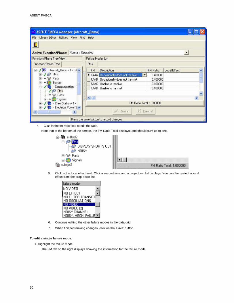
ASENT FMECA
50
4. Click in the fm ratio field to edit the ratio.
Note that at the bottom of the screen, the FM Ratio Total displays, and should sum up to one.
5. Click in the local effect field. Click a second time and a drop-down list displays. You can then select a local effect from the drop-down list.
6. Continue editing the other failure modes in the data grid.
7. When finished making changes, click on the ‘Save’ button.
To edit a single failure mode:
1. Highlight the failure mode.
The FM tab on the right displays showing the information for the failure mode.

The FMECA Manager
51
You can edit these fields:
FM Indicator
failure mode
fm ratio
local effect
1. Click in the Failure Mode field and select a new failure mode from the drop-down list. Alternatively click on the
‘new’ button ( ) to create a new failure mode library entry. When this button is clicked the entry form is presented.
Enter the name (and description if desired) and press the ‘OK’ button. The failure mode is added to the library and now appears in the Failure Mode window.
3. Click in the Local Effect field and select a new local effect from the drop-down list. Alternatively click on the ‘new’ button
( ) to create a new failure mode library entry which will be used as the localc effect. The same panel as above is presented with a different caption.
4. Click in the Failure Mode Ratio field to edit the ratio.
5. When finished making changes, click on the ‘Save’ button.
Copying Failure Modes
You can copy a group of failure modes from one assembly node to another assembly node. You can also copy a single failure mode to another FM bucket.
To copy a group of failure modes:
1. Highlight the FM bucket that has the failure modes you want to copy.

ASENT FMECA
52
2. Drag the failure mode bucket to the new assembly. The figure below shows the 'FMs bucket' of the 'Power' assembly being copied to the 'Monitor' assembly.
3. A panel is displayed with a list of all the Failure Modes in the 'FMs bucket'. Initially all of the Failure Modes are highlighted (selected for copying).
4. Select the Failure Modes to copy (or just hit 'OK' to copy all of them). Click on the failure modes to select them. You may also combine the mouse clicks with the Ctrl and Shift key. The figure below shows three Failure Modes highlighted for copy.
5. The failure modes are copied to the new assembly’s FMs bucket.
To copy a single failure mode:
1. Select the failure mode to be copied. Press the 'Ctrl' button.
2. Drag the failure mode to the new failure mode bucket and release both the 'Ctrl' button and the Left Mouse Button. This 'drops' the Failure Mode on the selected 'FMs' node. The following figure shows the '5 Volt B Undervoltage' Failure Mode being dropped on the 'CNTRLR' assembly.
The failure mode is copied to the new location.
If a confirmation panel is presented asking about Moving the Failure Mode, the 'Ctrl' button was not pressed (or was not all the way down) when the Failure Mode was selected. Respond 'No' and go back and try it again. Sometimes it takes a try or two to get the knack of it.
Defining Next Higher Effects
Defining next higher effects is the way you assign the link to the failure mode at the next higher level.
The Next Effects tab is where you link failure modes with their next higher effects. You may link or unlink next higher effects or edit the failure effects probability (beta). The Next Effects panel is scrollable.

The FMECA Manager
53
Next higher effects are simply failure modes at the parent or next higher level and editing next effects is similar to editing failure modes.
The Beta values represent a judgment of the percentage of the time that the identified failure mode will cause the indicated failure effect (NHE). The sum of the beta values cannot exceed 1.0. These beta entries are used to calculate the End Effect conditional probability numbers.
To link a failure mode as a next higher effect:
1. Highlight the failure mode under the Parent Failure Modes column.
2. Click the button.
The failure mode appears in the list under the Next Effects column and displays in the FMs bucket at the next higher assembly.
To unlink a next higher effect:
1. Highlight the failure mode to be removed from the list under the Next Effects tab.
2. Click the button.
The failure mode is deleted from the list of Next Effects and appears back under the Parent Failure Modes column.
To add a next higher effect from the FM library:

ASENT FMECA
54
1. Click on the button.
The Select New Effect window displays:
2. Select the new failure mode and then click OK.
The failure mode displays in the Next Effects column and is added to the FMs bucket at the Next Higher Assembly.
Viewing Causes
The Cause tab lets you look down the project tree to view the causes of failure modes. The list is view only.
The causes display for the highlighted failure mode.
The columns display failure modes that are the causes of the highlighted failure mode on the left. It also lists the source node of each cause and its contributing ratio to that failure.
To view causes:
Highlight a failure mode and click on the Causes tab.
The Causes tab shows the fail mode, the source node of that fail mode, and the contributing ratio.
If the item selected (assembly, part or signal) is on the lowest level of the tree (a ‘leaf’ node) then the ‘Causes’ tab provides the opportunity to input ‘root cause’ (or user defined cause) data.

The FMECA Manager
55
Enter the data, if desires and it will be reflected in the FMECA reports. The ‘OK’ and ‘Cancel’ buttons are initially inactive until one of the input windows is edited.
Viewing the End Effects
Selecting this tab allows you to quickly see all the end effects, severities, conditional probabilities and criticalities for the selected failure mode. Simply display this tab and the information is there along with a note as to the currency of the end effect data.
Creating FMIs
Failure Mode Indicatiors (FMIs) in conjunction to a Full Reference Designator or Logistics Control Number (LCN) can uniquely identify a failure mode within the procusto structure. The FMI is used I the LSAR as a key to many of the data records and often appears as part of the customed reporting requirements. FMIs are typically 4 letters and begin with the letter ‘F’ followed by three letters, sequencing from ‘AAA’ to ‘ZZZ’ for each assembly assembly or part, allowing over 17,000 failure modes for any given assembly, part or signal.
Failure Mode Indicators may be assigned directly, by typing in the FMI column in the Failure Mode Grid
, or by filling in the ‘FM Indicator’ field on the Failure Mode Tab.
A menu Item is also available on the System, Assembly and Failure Mode Bucket pop-up menus which will allow you to initially populate or re-assign. Selecting this option from the Failure Modes Bucket automatically repopulates the FMI for all the failure modes in the bucket.

ASENT FMECA
56
Selecting this option from an assembly node brings up a message panel allowing you to determine how far down the tree you want the assignment to proceed.
Calculating Criticality Numbers
The Criticality Calculation Tool performs two functions. The primary function is to calculate the End Effect Conditional Probability and Criticality Number for each failure mode in the system. In performing the calculations, however, a detailed examination of the failure mode / next effect relationships must be performed and all the primary information for the failure mode and next effect (such as failure rate, failure mode ratio, and end effect conditional probability) must be valid. Thus, the second function that the Criticality Calculation Tool provides is a detailed check of the reliability of the FMECA tree and FMECA data.
Before calculating criticality, perform these tasks:
Roll up failure mode ratios
Run the Check FMECA utility
To calculate criticality:
1. Highlight the system node and click on the right mouse button.
2. Select the Calculate Criticality option.
3. The FMECA Manager performs the calculations. You can stop the calculation at any time by pressing the Escape key.
4. After completing the calculations for the system, if there are problems with the calculation, the report option screen will display, otherwise the process is finished.
5. Enter a title for the Criticality Report and then click the Classification tab and enter a classification

The FMECA Manager
57
:
6. The Criticality Report displays. The format is similar to that used by the Check FMECA Tool and the Check Testability Tool.
Editing Detection Method
Clicking on the Detect Method tab brings up a free-form field to enter detection method information. This data is used in the FMECA reports and is provided to a LSAR Export.
To edit the detection method:
1. Click on the Detect Method tab.
2. Enter any pertinent information.
Editing Remarks/Actions
Clicking on the Remarks/Actions tab brings up a dual purpose data tab. The memo field at the top of the form provides the capability to enter additional reliability information. This data is used in the FMECA reports and is provided to a LSAR Export.
To edit reliability remarks:
1. Click on the Remarks tab.
2. Enter any pertinent information.

ASENT FMECA
58
3 Click on the 'Save' button.
The second function of this tab is to provide the capability to document the results of the Mishap Risk Analysis.
Drop down lists of the Mishap Risk Indexes from Mil-Std-882 are provided. You can either choose the Initial Mishap Risk
index from the drop down list, of the calculator button ( ) will calculate the Initial MRI based on the severity and probability shown in the End Effects tab for this failure mode. If you have a lot of failure modes that will be undergoing analysis, the 'Initialize Failure Mode MRIs will calculate the Initial MRI for every failure mode in the FMECA at a single stroke.
The Final MRI field is selected from the drop down list based on your judgement of the impact of the recommended action on the severity/impact of the risk.
Clicking the Target Completion Date drop down opens a calendar selector.

The FMECA Manager
59
This a very handy little item. Clicking on the arrows on the top will change the month forward or backward. The Month name can also be selected and a drop down of months is presented so you and go om November to February in 2 clicks. Likewise selecting the Year will provide a pick list of the month and year combinations. Selecting day from the calendar completes the selection and closes the drop down. The resulting date is then displayed.
You can also type directly in this field if you find it quicker.
Next to the calculator button is the 'information' ( ) button. Selecting this button brings up a display of the Mishap Risk Levels from Mil-Std-882 for your reference. .
ASENT FMECA
60
Editing Maintainability Remarks
Clicking on the Maintainability Remarks tab brings up a free-form field to enter maintainability information. This data is used in the FMECA reports and is provided to a LSAR Export.
To edit maintainability remarks:
1. Click on the Maintainability Remarks tab.
2. Enter any pertinent information.
Editing Compensating Provisions
Clicking on the Provision tab brings up a free-form field to enter provision information. This data is used in the FMECA reports and is provided to a LSAR Export.
To edit compensating provisions:
1. Click on the Provision tab.
2. Enter any pertinent information.
Performing Testability Analyses
Recommended Methodology for Testability Analysis
Prerequisites to performing testability include:
A completed FMECA analysis.
Define a Project tree.
Define Failure Modes/ Effects for all items.
Make sure Failure Mode Ratios and Failure Rates are defined at least for your lowest level (leaf) items.
Run Check FMECA (Utility menu) to ensure that all failure modes have next higher effects. You do not have to calculate criticality.
Roll-up Failure Mode Ratios.
Define detection/isolation groups (in the Library Editor).
Define detection codes.
At lowest level, enter Testability Data for all Failure Modes.
Enter detection name (code), excluded and detected ratios, and isolation lists for each group.
Run Check Testability (Utility menu) to see if any intermediate nodes have been user set.
If user sets exist, run Initialize Testability if the entire tree should be considered for calculation. If not, then do not run the utility. The Check Testability tool will also identify Failure Modes without Testability information as well as whether the Testability Calculations are current.
Calculate Testability.
Run Check Testability to assure that everything is complete.
Generate Reports.
Defining Detection/Isolation Groups
Detection/Isolation groups must be defined in the Library Editor before you can enter or edit testability data.
See Editing the Detection/Isolation Groups Library.
Initializing Testability
If you select initialize testability from the system node with a right click, you can reset userset leaf settings so you can perform testability all the way down the project tree.
To initialize testability:
1. Highlight the system node and click on the right mouse button.

The FMECA Manager
61
2. From the menu, select Initialize Testability.
The FMECA Manager resets all intermediate testability records and sets actual leaf nodes to true. Actual Leaf Nodes are the lowest nodes where testability data exists, not necessarily the bottom of the tree.
Editing Testability Data
The Testability tab provides the capability to edit the data for detection/isolation groups, including the isolation list and alternate BIT detail for each defined detection/isolation group. Before entering testability data, your groups should have been previously entered in the Detection/Isolation Groups Library using the Library Editor. The data entered on the testability tab appears in the Testability Analysis report.
If one of the detection/isolation groups is defined as being comprised of parts, the tool identifies the corresponding node in either the Reliability Manager or FMECA project tree and builds a list of the assemblies or parts. What is displayed depends on what
was selected when the group was defined the source was defined as either Reliability Manager or FMECA and source type was defined as either assembly or parts.
The testability tab is available from all failure modes in the FMECA tree. Testability data is entered for a given failure mode.
The following figure shows testability data for a selected failure mode:

ASENT FMECA
62
The Resize Hot Spot is highly convenient when working with the testability information. Clicking it once opens the grin to full panel, revealing more of the group data with minimal scrolling.
To edit testability data:
1. Highlight the failure mode whose testability data you want to edit.
2. Click on the Testability tab.
3. Click on the plus sign to add a new record.
4. Enter the testability data in the fields as described in the following table:
Field: Description:
Group Click once in the field to display a selection button. Click on the button to display a list of groups.

The FMECA Manager
63
The groups must have been previously defined in the Library Editor.
Category Click once in the field to display a selection button. Click on the button to display a list of Categories
Selecting a category will blank out the selection in the detection code column.
Detection Code Click once in the field to display a selection button. Click on the button to display a list of detection names in the selected category. This could be Yes or No to indicate whether the failure is detected by a particular group. Typically, this would be one or more test codes or test numbers that detect the failure.
Excluded Ratio Enter the ratio that represents the portion of the failure mode that is to be excluded from the selected detection group.
Detected Ratio Enter the ratio that represents the portion of the failure mode that is detected by the selected detection group and detection name.
False Alarm Enter the ratio that represents the portion of the failure rate that is characterized by incorrect BIT failure indications.
FR Applicable Amount of the failure rate that is applicable. Detection - excluded. Calculated field.
FR Detected Amount of the failure rate that is detected per group. Calculated field.
FR False Alarm Amount of failure rate attributable to incorrect BIT failure indications. Calculated field.
FR Analyzed Amount of the failure rate that has testability data entered. Indicates completeness of analysis. Calculated field.
FR Iso Level1 FR Iso Level2 FR Iso Level3
Previously defined when defining detection/isolation groups in the Library Editor. Calculated fields.

ASENT FMECA
64
Userset Leaf Item Click once in the field to display a selection button. Select True or False.
When set to True, the selected record is associated with the last child in the tree and is treated as the last leaf when calculating testability. It also appears as the last leaf in the testability report.
See Calculating Testability
Actual Leaf Item Set to true if this is actually a leaf item in the tree.
Comment Click in the field and type your comment. The comment will be saved when you save your editing changes or change selected Detection/Isolation Groups.
5. To add another record, click on the button or use the down arrow key.
6. When finished making editing changes, click on the Save button
Editing the Isolation List
You can define an isolation list that lets you identify the items to which you can isolate the cause of a failure mode. You can order the list to show the items in suggested order of troubleshooting or failure rate or any other driving rationale.
The isolation group is populated by adding the members of the group from a list of candidates. The testability record selected determines what is presented in the list of available nodes. A list of parts or assemblies display, depending on which was selected for the detection/isolation group in the Library Editor.
The ‘Source’ selection determines which tree is used to supply the list of parts or assemblies. When ‘Assembly’ is selected as the ‘Source Type’, the ‘Isolation Type’ is used to retrieve the list of candidates from the specified tree. For example, when ‘SRA’ is chosen as the Isolation Type, and the ‘Source‘ is ‘Reliability’, the isolation candidate list will be comprised of those assemblies in the Reliability Manager Product Tree which have their ‘Assy Type’ set to ‘SRA’.
If the currently selected part or assembly has the ‘Isolatable’ check box checked, it will automatically be added when the list is opened, otherwise the tree will be searched upward until a parent assembly is found with the ‘Isolatable’ check box checked, and that parent assembly will be automatically added to the isolation list. The following figure shows the parts of the Isolation List screen:

The FMECA Manager
65
To edit the Isolation List:
1. Highlight the failure mode whose isolation list you want to edit.
2. Click on the Testability tab.
3. Highlight the group whose isolation list you want to edit.
4. Click on the Edit Isolation button.
5. Under Available Nodes, select the node that you want to isolate to and click the Add button.
The selected node appears to the right under the Selected Nodes column. 6. Use the Up Arrow and Down arrow buttons to order the isolation list in the desired order.
7. Click on the ‘Save’ button to save the changes.
When you return to the testability data window, the name, full rd and failure rate from the isolation list displays for the currently selected item:
Editing Alternate Testability Data
You can add alternate testability data by clicking on the Edit Detail button. It is in the edit detail area that you record information about alternate tests or several tests grouped under a given name. This allows you to substitute tests in and out for “what-if” analysis. Adding alternate testability data is entirely optional.
In addition, each alternate test can have its own isolation list. To edit this isolation list, go into the BIT detail record and then edit the isolation list of the BIT detail record. See Editing the Isolation List.
After defining the record, you can select the Replace BIT detail button to use the data in your calculations.
In the example, a failure mode, Bad Memory, has two detection/isolation methods defined:
To edit BIT detail:
1. From the testability tab, select the testability record for which you want to edit BIT detail.
2. Click on the Edit Detail button.
3. On the BIT Detail screen, click the plus sign for a new record.
4. Enter the BIT detail data in the fields as described in the following table:
Field: Description:

ASENT FMECA
66
Detection Name Click once in the field to display a selection button. Click on the button to display a list of detection names. This could be Yes or No to indicate whether the failure is detected by a particular group. Typically, this would be one or more test codes or test numbers that detect the failure.
Excluded Ratio Enter the ratio that represents the portion of the failure mode that is to be excluded from the selected detection group.
Detected Ratio Enter the ratio that represents the portion of the failure mode that is detected by the selected detection group and detection name.
False Alarm Enter the ratio that represents the portion of the failure mode resulting in false bit indications.
Comment Any existing Comment is automatically displayed. Click in the window and enter your comment.
5. Click on the button to save your edits.
You can now create or edit an isolation list for your alternate testability data. See Editing an Isolation List.
To replace a group’s testability data with BIT detail data:
1. In the BIT Detail screen, select the record with the data you want to use in the testability calculation.
2. Click on the Replace BIT button.
The currently selected group’s data is replaced with the data in the record you selected.
Copying Testability Data
The capability to copy testability data from one failure mode to many others can provide a significant productivity lift for widely used test mechanisms, such as periodic or initiated BIT, where a large number of functions, hence potential failure modes, are tested. Data for many detection methods may be copied to either selected failure modes on one assembly, or all the failure modes on multiple assemblies in a single operation. Copying testability data is a straight forward process. To begin the process, select the Group/Detection Code data to copy in the upper portion of the Testability Tab and press the ‘Copy Data’ button (shown circled in the lower right hand corner of the figure below).

The FMECA Manager
67
A panel is theen presented to allow you to choose the Testability Data to copy.
Pressing the ‘OK’ button after selecting the type of data to copy proceeds to the next step in the process. If you selected to copy the BIT Records, the next step is which is selecting the BIT Records to copy. A panel is presented with all the BIT records of the currently selected failure mode.
All the available BIT records are initially selected (highlighted in Blue). use the traditional Windows Ctrl+Click and Shift+Click methods to select or unselect the various records until only the records you are interested in are highlighted and press the ‘OK’ button.

ASENT FMECA
68
This step is not needed if only the isolation list is selected. The isolation list for the selected BIT record will be the item copied. If the currently selected project has more than one FMECA (function/phase combination) a panel will be presented with a listing of all the FMECAs for the current project. Select the FMECA that will receive the testability data.
After selecting the FMECA (if necessary), a panel will be presented for you to select the type of destination (one assembly or multiple assembies) for the copy.
Selected Failure Modes on a Single Assembly
If this option is selected, after pressing the ‘Ok’ button, the system node of the product tree of the selected FMECA is presented in a Tree View panel. Expand the tree until you can select the assembly that will receive the copied testability data.

The FMECA Manager
69
When the selected assembly is highlighted and the ‘Ok’ button is pressed, the Failure Modes for the selected assembly are presented. As a default, all the failure modes are initially selected.
This is a standard multiple selection grid and the ‘Ctrl-Click’ and ‘Shift-Click’ keystrokes work in their normal fashion to select or deselect items or spans of items. After you get the failure modes of interest selected, press the ‘Ok’ button. The testability data, including the Isolation List, is copied to the selected failure modes and wil appear when the Testability Tab for those failure modes is selected.
All Failure Modes on Multiple Assemblies
If this option is selected, after pressing the ‘Ok’ button, a selection panel with the list of assemblies in the product tree, in a product tree like layout is presented.
This is a standard multiple selection grid and the ‘Ctrl-Click’ and ‘Shift-Click’ keystrokes work in their normal fashion to select or deselect items or spans of items. After you get the assemblies of interest selected, press the ‘Ok’ button. The testability data that you selected, either the BIT Records and the Isolation Lists or simply the Isolation List for the selected BIT record, is copied to all the failure modes of the selected assemblies and will appear when the Testability Tab for those failure modes is selected.
Calculating Testability
The Calculate Testability option lets you calculate fault detection, isolation and false alarm numbers, which are crucial for determining test coverage, isolation percentage, and false alarm rate metrics.
The tool works its way from the bottom of the tree and determines the significance (based on excluded ratio) of each group for each failure mode as well as the detectability for the selected node and all the children nodes. These determinations are based on the excluded and detectable ratios of all the causes of the failure mode.
For groups whose isolation groups are composed of assemblies, the isolation groups are built by combining the isolation groups for all the causes of the failure mode.
Selecting the Calculate Testability option from the system node with a right mouse click, or selecting the Calculate Testability option from the Utilities menu of the Main Menu, begins the calculation.
You may calculate testability for the entire project or a portion of it depending on whether you set items as leaf items.
If you set intermediate nodes to leaf items, then the calculator treats these items as the bottom of the tree and calculates from your user set bottom up to the project node. This may be done early on in the design. As more definition is available, these

ASENT FMECA
70
intermediate user sets can be cleared so that the calculator considers the entire tree. These user set flags are cleared by selecting the Initialize Testability option from the project node. See Initializing Testability.
To calculate testability:
The testability calculation may be invoked from either the System Node menu or the Utilities option of the Main menu. To select the calculation from the System Node, highlight the System Node and click with the right mouse button:
Select the Calculate Testability option.
When the System Node is not readily available, such as when you are far down in an extensive product tree, the calculation is still readily available. Select the Utilities option of the main menu:
Select the Calculate Testability option.
Performing RCM Analyses
The RCM Data Tab
The RCM Method for a project is set in the Project Data Tab of the Session Manager, as it will apply to all FMECAs for the project. The RCM Tab is available on the system node and all assembly nodes.

The FMECA Manager
71
The ‘Status’ and ‘RCM Results’ data display reflect the results for the selected failure mode, indicated by the arro on the left side of the failure mode grid. Moving the selection, by pressing the up or down arrow keys or clicking on another failure mode with the left mouse button will update the displayed results to reflect the newly selected failure mode.
The lower portion of the tab displays the RCM tasks for the selected failure mode, their preliminary and packed interval and locations for the Units (Hours, Days, Weeks, Months, Years) of the intervals, the level at which the task will be conducted, and the task type. The same task from the library can be identified as different task types depending on the needs of the analyst. The up and down buttons on the bottom toolbar allow you to arrange the tasks in the sequence you desire.
Each RCM Task has 3 text items associated with it:
1. The Library Notes/Status field which is available at all usages of the task.
2. The Description Field, also 255 characters, which provides an opportunity add a
description of the use of the task for this failure mode. The ‘Add Task Desc’ button
allows you to view and edit the description.
3. The Local Note, , also 255 characters, which provides an opportunity to specify
anything unique or applicable to the use of the task for this failure mode. The ‘Edit
Task Notes’ button allows you to view and edit the local note.
Conducting the RCM Analysis
RCM Analysis is conducted on a failure mode by failure mode basis. The first step in conducting the analysis is to select a failure mode on the RCM Tab. Then click on the ‘Conduct Analysis’ button. This displays the questionnaire panel.

ASENT FMECA
72
The top part of the panel displays the System Effects (End Effects) of the selected failure mode. If there is more than 1 effect,
then a button ( ) is presented which allows you to view the spectrum of end effects associated with the selected failure mode. Pressing this button presents the end effects and their severity.
The first potion of the RCM logic is to determime whether the failure mode results in identification as Structurally Significant Item, a Functionally Signficant Item or a NonSignificant(NonCritical) Item. The questions to make the determination are presented in the lower portion of the panel. Each answer prompts the next question until a determination is made.

The FMECA Manager
73
If you decide you want to change the answer to a previous button, press the ‘Back’ button. Once a determination has been made, if the determination is ‘NonSignificant Item’ then the analysis for the failure mode is complete and the RCM tab is displayed with the results in the top part of the tab. For SSIs and FSIs the title on the question box changes and the questions for the appropriate item type are presented.
When the logic series has ended, the results are updated and the RCM tab is displayed with the results in the top part of the tab. Pressing the ‘Abort’ button at any time the Decision Logic panel is displayed returns to the RCM tab without any data modification.
Copying RCM Data
Quite often many assemblies have a similar failure mode with the same RCM results and, in these cases the ‘Copy RCM Data’ button at the bottom of the RCM tab can provide a significant productivity lift, allowing you to copy the RCM results without going through the questionairre for each assembly.
Select the failure mode in the failure mode grid on the RCM tab that has the RCM results you want to copy. Click ob the ‘Copy RCM Data’ button. The Assembly Selection panel is presented.
Expand the tree until the assembly of interest is displayed . Select the assembly and press the ‘OK’ button. A selection panel of the failure modes on the selected assembly are presented. Initially all the failure modes are selected (highlighted).

ASENT FMECA
74
Use the standard Windows approach of holding the Control button (Ctrl) and clicking with the left mouse button to de-select individual failure modes. Select a single failure mode by simply clicking the left mouse button on the failure mode of interest. It will become the only selected failure mode. You may individually add others by Ctrl+Left Mouse button clicking. The Shift+Click method to mark a span of failure modes also works.
Press the ‘OK’ button and the RCM data is copied to the highlighted (blue) failure modes.
Maintaining the FMECA
Calculating Failure Mode Ratios
The Roll-up Failure Mode Ratios is available from the project node and the Utilities submenu of the Main Menu. The tool works its way from the bottom of the tree and recalculates all the failure mode ratios for the selected node and all its children nodes. This ensures that the ratios are consistent and correct throughout the tree, which is crucial for correct calculation of the criticality numbers. Prior to doing the FM Roll-up, you should verify that failure rates are defined at the lowest level and that failure mode ratios are defined for failure nodes at the lowest level. Also, next higher effects should be defined for all of the failure modes in your project.
To calculate failure mode ratios:
1. Highlight the project node and click on the right mouse button.
2. Select the Roll-up Failure Mode Ratios option.

The FMECA Manager
75
3. ASENT recalculates all the failure mode ratios for the project tree.
4. When the calculation is complete, the cursor in the project tree again becomes active.
Check FMECA
The Check FMECA tool is a general purpose check of the FMECA and will accurately report any problems which will inhibit the capability to generate reports or to export data to the LSAR and set the status flag in the FMECA tree to help you quicly find any problems in your FMECA. It provides an extensive check of the FMECA in a very rapid manner, typically taking a minute or less, even on FMECAs containing thousands of failure modes. One of the ways that it achieves this speed is by providing the data in usable sized ‘chunks’. When it finds a widespread problem, it only reports on the first 200 incidences found, rather than bury you in data that you probably have already figured out by reading the first 200 reports.
The items that the Check FMECA Tool will identify are:
Incomplete or outdated criticality numbers
Failure mode ratios not summed up the product tree
Undefined end effects
Failure modes without next effects
Failure Modes with Next Effects not on the parent assembly.
Failure modes without causes
Failure modes with conditional probabilities not equal to 1
Assemblies, parts, or signals with failure modes less than or equal to zero
Assemblies, parts, or signals without failure modes
Assemblies, parts, or signals without full reference designators
Assemblies and Parts with invalid links.
Linked parts with a total failure rate ratio not equal to 1.00
It is generally advisable to run this utility prior to generating a report to ensure that the analysis is ready for reporting or review.
As the FMECA is checked, the Check FMECA box displays the status.
When the check is complete, the Check FMECA Report displays only if there are errors.
To run the Check FMECA tool:
1. From the Utilities menu, select Check FMECA.
2. An Options panel is presented to allow you to tailor how the check is performed and how it reports the results

ASENT FMECA
76
3. You may limit the number of errors reported from each check, to prevent the report from becoming to overwhelming, or you may have the report contain all errors found. The second and third check boxes allow you to direct the tool to check the reference designators of assemblies, or you may leave it blank if you know that you are not using reference designators. The fourth check box allows you to report on any items linked to parts in the reliability tree which have total failure rate ratios (set in the linking) which are not equal to 1.
4. When errors are found, the tool will report the location of the error using a trace string of assemblies such as:
ThisSystem -> RECEIVER CONVERTER FM: NO VIDEO
The next two check boxes will allow you to include the LCN and / or reference designator to the string to aid in identifying the problem area. The example below shows the results from checking the LCN check box.
ThisSystem LCN:LPY -> RECEIVER CONVERTER FM: NO VIDEO
5. Status messages display such as “Starting Check FMECA,” “Performing Queries,” or “Generating Error File.” When the check is complete, if there are errors, the report is displayed using the Windows Notepad tool.
6. If the Check FMECA tool completes the analysis, that is it does not come to the limit of the number of problems for any given problem type, the status flags are rolled up the system to the top node. If the maximum number of problems are reached, the status flags are NOT rolled up, leaving the system node in the ‘undetermined’ status.
Update Failure Rates
The Update Failure Rates Tool updates the FMECA part failure rates with the current ASENT failure rate prediction values for the project. The correlation between ASENT and FMECA Assemblies is based on the linkage established using the ‘Link’ menu item of the System and Assembly menus. Importing new values will overwrite existing values.
Notes:
Failure rates will be updated for assembly nodes, linked Signal Nodes, and Part nodes on linked assemblies. Failure rates for intermediate assemblies (those with other assemblies, parts or linked Signals ) will be summed from the bottom up.
Failure rates will be updated for signals if the 'Signals' node is the ONLY child of the parent assembly. The 'Parts Bucket' and 'FMs' nodes must both be empty.
Failure rates will NOT be updated for signals and parts, or assemblies linked to parts if a User Defined Field is selected as the source for the update.

The FMECA Manager
77
To update failure:
1. From the Utilities menu, select Update Failure Rates.
The Update Failure Rate tool main panel is presented. To begin the update, select a field to use for the new data and press the ‘Start’ button.
If you have selected a user defined field (like the Alt MTBFs item in the pull down) you will be advised and asked if you want to proceed:
If you select ‘Yes’ then you will be asked if the data in the user defined field is in the form of an MTBF, if so answer yes, otherwise answer no.
2. The progress of the update process is indicated by a progress bar on the main panel. When the update is complete, the diagnostics from the update are displayed in the center of the panel.

ASENT FMECA
78
3. The report lists each updated node or reference designator and the old and new failure rates, and the status of each failure rate update. From this screen you can Print or save the diagnostics to file, using the ‘Print’ and ‘Save’ button. You also have the option of modifying the font that the diagnostics report uses by selection the Options item of the main menu, ‘Font’ menu item and selecting the font, color and any style attributes you desire from the Font Dialog.
4. When you are finished reviewing the report, return to the FMECA manager by Clicking the OK button or closing the Update tool (using either the ‘x’ in the upper right hand corner or the ‘File|Exit’ menu item.
Check Testability
The Check Testability tool generates a report of all the failure modes that have the userset leaf flag set to true.
To run the Check Testability tool:
1. From the Utilities menu, select Check Testability.
2. The Testability Checker tool is presented.

The FMECA Manager
79
3. The ‘Options’ menu item provides option of modifying the font that the diagnostics report uses by selection the Options item of the main menu, ‘Font’ menu item and selecting the font, color and any style attributes you desire from the Font Dialog. You may also select the maximum number of items reported from each check performed by selecting the ‘Limits’ menu item.
4. Selecting this option brings up a panel which will allow you specify whether you want the output limited, and the limit for each check. The default setting is to limit the output to 25 items for each check.
5. Press the ‘Start’ button to initiate the check. When the check is complete the diagnostics from the check are presented in the center of the panel.

ASENT FMECA
80
6. The diagnostics report identifies each check attempted and the result of the check. If you have selected to limit the number of findings for each check and the limit is exceeded, in a given check, the specified number of findings are listed and a note to the effect that the list was truncated is appended to the list. From this screen you can Print or save the diagnostics to file, using the ‘Print’ and ‘Save’ button.
7. When you are finished reviewing the report, return to the FMECA manager by Clicking the OK button or closing the Update tool (using either the ‘x’ in the upper right hand corner or the ‘File|Exit’ menu item.
Creating LCNs
Selecting this item of the Utilities menu begins a check for any assemblies which already have Logistic Control Numbers (LCNs) assigned. If any are found, it presents a warning panel.
Selecting the ‘No’ button terminates the process and returns you to the main menu with modification of any existing data. Clicking the Yes button displays the input panel for the next step of the process.

The FMECA Manager
81
The FMECA Manager determines the number of levels in the product tree from the selected assembly and provides an input box for each level. Type the Logistics Control Number for the selected assembly in the ‘This Assy LCN’ box. This will be used as the base for all the lower level LCNs. Then enter the Width (in number of letters) for the additional LCN for each level. These are defaulted to 2 letters when the panel is initially presented, as it is the most commonly used.
The panel immediately below the Levels window provides you the selection of the assignment method the tool will use. Selecting the first radio button will assign the first assembly below the currently selected assembly with the LCN ‘GAAA’ based on the selections shown in the panel. The same assembly will be assigned ‘GA00’ if the second radio button is selected and ‘GA01’ if the third radio button is selected.
Some customers may not allow an 'O' or an 'I' in the LCN since it may be confused for a 0 or 1, so the utility gives you the ability to skip these letters when creating LCNs.
The Increment options specify how the LCNs will transition after the number '9'. The first radio button will transition to 'A' and progress to 'Z' before advancing to '10'. the second will maintain pure numerics and skip the letters, but this will result in a much smaller number of possible items for a given indenture level for a given field length.
The Depth option box allows you to specify whether you want to assign LCNs for the entire subtree, or only the immediate next lower level.
Pressing the ‘Cancel’ button terminates the process and returns to the main menu without data modification. Pressing the ‘OK’ button starts a check which determines the length of the longest LCN that will be generated. If this longest LCN exceeds 18 characters (the maximum presently supported by most commonly available LSAR tools) then a warning menu is presented and you are returned to the input panel to pare down either the top level LCN or the selections you made for the levels. Once the LCN structure is compliant with this limitation, LCNs are generated and the Product tree collapsed. Upon expansion, the new LCNs are then visible.
Generating Reports
Generating the FMECA Reports
The Reports in the FMECA Manager are available from the 'Reports' option of the assembly, signal, or failure mode pop-up menu. Select one of these items, Right Click with the mouse and the pop-up menu displays. Selecting the 'Reports' menu item brings up the menu of available reports. The 'Failure Modes Library' and 'Signal Library' reports are only available from the project (system) node. The figure below shows the selections from the project (system) node.

ASENT FMECA
82
The Testability submenu contains an additional 7 reports, and the Metrics submenu contains an additional 2 reports to those presented on the Reports submenu.
There are four types of reports available from the FMECA Manager, those that generate an Excel spreadsheet output, those that generate a text file output (presented with NotePad), those that generate a Rich Text output, and those that use the Crystal Reports presentation. The reports that generate Excel spreadsheets include:
FMEA
BIT Design Impact Report
Custom Excel FMECA Report
Item Criticality Matrix Report
Testability Spreadsheet
Test Coverage Summary
Assy FM Test Report
Isolation List Overview
FMECA User Defined Report
Part Link List Report
False Alarm Analysis Report
FM Criticality Matrix Report
Failure Category Report
RCM Reports
FMECA Safety Report
FMECA Export
FMECA GJB1391 Report

The FMECA Manager
83
The generated spreadsheets are presented using Excel at the time the report is run. EXCEL (version 8 or later) MUST be installed on your computer (either locally or through the network) for these reports to create a spreadsheet. The Testability Reports are contained in a submenu that is displayed when the ‘Testability’ item is selected from the Reports submenu. For the Excel reports, if you want to save the report, select ' File|Save As' from the Excel main menu, navigate to the location where you want the report saves, give the report a name and click the Save button.
The FMECA Export report is covered in the Exporting FMECA Data help book.
The metrics reports are text files and are presented with Notepad at the time the report is run. Selecting the Metrics Reports item open a submenu with the following reports:
Count Failure Modes
Count Detection Codes
The only report that currently generates a Rich Text output is the Check Part Links report. This report is patterned after the Check FMECA and Check Testability utilities.
The following reports use the Crystal Reports presentation:
FMECA
End Effects Criticality Numbers
End Effects to Causes (Trace Report)
Failure Mode Library Listing
Signal Library Listing
Custom Crystal FMECA Report
Critical Failure Modes Report
Critical Items Reports
The reports that use the Crystal Reports presentation present a dialog panel to allow users to specify a title and a classification. In most cases, a default title is presented as a template
If a title and classification are not desired, merely blank these fields out when they appear on the report window.
Arrows at the top of each report let you page through the report and quickly get to the top or bottom of the report.
The following figure shows the labels for the icons at the top of the report screen:

ASENT FMECA
84
You may also resize the report window by grabbing the corners or edges with the mouse and dragging. The 'Page Down' and 'Page Up' keys may also be used to move in the currently displayed page. The 'Ctrl'+'Page Down' and 'Ctrl'+'Page Up' may be used to shift between pages in the report.
The Excel and Rich Text format reports have a more extensive user interface, allowing you to specify various options for data selection. These details of these reports are covered in separate sections of this Help file.
The FMECA User Defined Report has such extensive options that it has its own Help file.
Assy FM Test Report
Selecting the ‘Assy FM Test Report’ menu item from the Testability submenu of the ‘Reports’ menu invokes the report.
The initial panel is presented to provide you the option to specify a title an a classification for the report. Both items are optional. If a classification is entered, it will be added to the report as the first and last lines of the page, as is the common requirement for labeling of classified material.
There are optional data that the user may want to include in the report. Click on the check boxes of those desired.
The report is available from any assembly in the FMECA Tree, and can provide the report for only the selected node or the entire subtree of the selected node. Checking the ‘Include SubAssemblies’ item will generate the report for the entire subtree of the selected node.
You can change the pagination of the report to better suit your printer by changing the ‘Lines per page’ number. This is the number of rows of data per page and includes the report header and classification footer (if any). Excel rows can vary widely basically due to word wrapping in the descriptive columns of the report, so this control allows you to easily ‘fine tune’ your report for print.
Options are provided to allow you to specify what information you want displayed in the identification of the assembly being analyzed. The Assembly name will always be printed, the LCN, part number and Ref Des will be added to the assembly identification line based on the options you check.
Additional columns are available if you have data in the ‘Comment’ field of the Testability tab or in one of the ‘Provicsion’, Remarks, Detection Method or Maintenance Remarks tabs of the failure mode. The bottom two checkboxes allow you to select

The FMECA Manager
85
which (if either) column you want added to the report. Selecting the ‘Test Points’ column activates a Radio Button Group to allow you to select which of the tabs of the failure mode that the information is that you want presented in the ‘Test Points’ column.
The ‘Items Causing’ column of the report will identify all the items which cause the failure mode being listed on the line. Radio buttons are provided to allow you to specify how these causing items are identified.
After selecting the desired options, pressing the ‘OK’ button proceeds to the next step which is selection of the Detection Groups. A panel is presented with all the defined detection groups listed by their detection titles.
Select the detection group you want presented in the report. These are the same type check boxes as in the ‘Options’ menu previously presented. When you have selected the groups you want, press the ‘Ok’ button to continue. Pressing the ‘Abort’ button cnacles the report and returns you to the FMECA Manager. This is an excellent time to review your detection titles, and if they are not what you want, press ‘Abort’, go to the Library Editor and modify them to your liking.
Next the Isolation Groups are presented for selection. They are presented with the Isolation Titles, as they will appear in the report. Again if they are not what you want, press ‘Abort’, go to the Library Editor and modify them to your liking.

ASENT FMECA
86
Press the ‘Ok’ button when you have selected the isolation groups you want presented in the report. You will then be offered the opportunity to determine the order (left to right) that the selected detection columns will appear in the report.
A group is moved by highlighting the group and clicking on the up and down arrows until the groups are in the desired order. Press the ‘OK’ button when the groups are in the desired order. You will then be presented with a similar panel to order the selected isolation groups. Press the ‘OK’ button when the groups are in the desired order. Pressing the ‘Abort’ button on any of the previous panels aborts the report and returns you to the FMECA Manager.
If you selected to add the ‘Test #’ column to the report, the next panel is presented to allow you specify detection group where the comments are located, as you can enter comments for each group.

The FMECA Manager
87
The next panel presented provides you the option of specifying the order that the detection groups are presented in the report.
To move a group, select the group, so it is highlighted and press the up or down arrows on the right side of the panel. Press the ‘OK’ button when you have the groups in the order you desire.
A similar panel is presented for the isolation groups. Place these in the order you want them to appear in the report, Press the ‘OK’ button when you have the groups in the order you desire. A status panel is presented which details the progess of the report and the current report activity. When the report is complete, the Excel spreadsheet is presented.
BIT Design Impact Report
This Testability report provides a ‘Tree’ presentation of the testability analysis data with a line for each assembly, followed by a line for each failure mode (if selected) and a line for each set of detection codes (if selected) for each of the selected detection groups. The isolation percentages presented in the report at the failure mode level are the highest of any group in the the failure mode divided by the modal failure rate for the failure mode. The isolation percentages presented at the assembly level are the sum of the isolated failure rates for all the failure modes of the assembly, divided by the assembly failure rate.
Selecting the ‘Bit Design Impact Report’ menu item from the Testability submenu of the ‘Reports’ menu invokes the report.
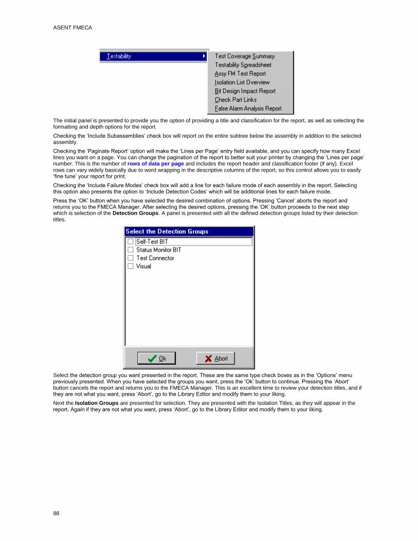
ASENT FMECA
88
The initial panel is presented to provide you the option of providing a title and classification for the report, as well as selecting the formatting and depth options for the report.
Checking the ‘Include Subassemblies’ check box will report on the entire subtree below the assembly in addition to the selected assembly.
Checking the ‘Paginate Report’ option will make the ‘Lines per Page’ entry field available, and you can specify how many Excel lines you want on a page. You can change the pagination of the report to better suit your printer by changing the ‘Lines per page’ number. This is the number of rows of data per page and includes the report header and classification footer (if any). Excel rows can vary widely basically due to word wrapping in the descriptive columns of the report, so this control allows you to easily ‘fine tune’ your report for print.
Checking the ‘Include Failure Modes’ check box will add a line for each failure mode of each assembly in the report. Selecting this option also presents the option to ‘Include Detection Codes’ which will be additional lines for each failure mode.
Press the ‘OK’ button when you have selected the desired combination of options. Pressing ‘Cancel’ aborts the report and returns you to the FMECA Manager. After selecting the desired options, pressing the ‘OK’ button proceeds to the next step which is selection of the Detection Groups. A panel is presented with all the defined detection groups listed by their detection titles.
Select the detection group you want presented in the report. These are the same type check boxes as in the ‘Options’ menu previously presented. When you have selected the groups you want, press the ‘Ok’ button to continue. Pressing the ‘Abort’ button cancels the report and returns you to the FMECA Manager. This is an excellent time to review your detection titles, and if they are not what you want, press ‘Abort’, go to the Library Editor and modify them to your liking.
Next the Isolation Groups are presented for selection. They are presented with the Isolation Titles, as they will appear in the report. Again if they are not what you want, press ‘Abort’, go to the Library Editor and modify them to your liking.

The FMECA Manager
89
Press the ‘Ok’ button when you have selected the isolation groups you want presented in the report. You will then be offered the opportunity to determine the order (left to right) that the selected detection columns will appear in the report.
A group is moved by highlighting the group and clicking on the up and down arrows until the groups are in the desired order. Press the ‘OK’ button when the groups are in the desired order. You will then be presented with a similar panel to order the selected isolation groups. Press the ‘OK’ button when the groups are in the desired order. Pressing the ‘Abort’ button on any of the previous panels aborts the report and returns you to the FMECA Manager.
A status panel is presented providing you with information as the report is generated. When the report is copleted, the Excel spreadsheet is presented. Use the ‘File’ menu of Excel to save the spreadsheet if desired.
Check Part Links Report
The Check Part Links Report provides a quick but comprehensive view of the links of an assembly or signal that is linked to parts in the Reliability Tree. Selecting this report brings up the main panel of the report.

ASENT FMECA
90
The main menu of this report provides two options: ‘File’ and ‘Options’. The only selection on the ‘File’ menui is ‘Exit’ which terminates the report and returns to the FMECA Manager. The options menu also has only one selection, ‘Font’. This selection brings upa dialog which allows you to specify the Font that you want used in the report.
Pressing the ‘Start’ button initiates the report and the center portion of the panel presents the body of the report.
The report identifies all the parts on the Reliability Tree Node. The report is divided into two parts. The first part of the report lists all parts on the reliability tree that are not linked. This will help resolve any differences in failure rate between the FMECA tree and the Reliability Tree. The second portion of the report will identify all parts on the Reliability Tree Assembly where the sum of the linkages is not equal to one. From this screen you can Print or save the diagnostics to file, using the ‘Print’ and ‘Save’ button.
When you are finished reviewing the report, return to the FMECA manager by Clicking the OK button or closing the Update tool (using either the ‘x’ in the upper right hand corner or the ‘File|Exit’ menu item.
Custom Crystal FMECA Report
This menu item is intended to be a place holder for a custom report for your company or project in Crystal Reports format. This menu item is currently populated by a report format requested by a customer, but is easily replaceable with a report customized for your application.
Custom Excel FMECA Report
The Custom Excel FMECA Report is a FMECA Report in Excel Format and is intended to be a placeholder for a customized report for your company or project in Excel Format. It is currently populated with a format requested by a customer, but can be easily replaced.
Selecting this menu item from the Reports submenu brings up the options panel of the report.

The FMECA Manager
91
Enter a title, if desired, for the report and a classification, if desired. Both of these items are optional and the report will work well with both fields blank.
Pressing the ‘OK’ button starts the report generation. The report will check the currency of the Criticality Calculations, and, if current, will run through the assemblies. At the conclusion the Excel spreadsheet will be presented.
False Alarm Analysis Report
The False Alarm Analysis Report is a worksheet that summarizes the False Alarm Rate and other selected testability information at a user selected level. The user has a number of options concerning both the data presented and the format of the presentation.
Selecting the ‘False Alarm Analysis Report’ item from the ‘Testability’ submenu of the Reports menu initiates a check to assure that the required data, such as detection and isolation groups, have been defined. When the check has been successful, a panel with the report options is displayed.
In addition to the standard Title and classification options the follow are available for the user to tailor the report:
Include Subassemblies – Selecting this option will add report rows for all the assemblies in the subtree below the selected assembly in addition to the row for the selected assembly.

ASENT FMECA
92
Print Failure Modes – Selecting this option changes the title of the ‘Description’ column to ‘Description/Det.Name’. It will also add lines for each failure mode to the report. Leaving this option blank will limit the report to 1 line per assembly, summarizing the data at the assembly level. (selecting both of the above options also give you the option to paginate the report between assemblies, as shown in the figure above).
Include FR Analyzed – Selecting this option adds a ‘FR Analyzed’ column to the spreadsheet.
Include FR Excluded - Selecting this option adds a ‘FR Excluded’ column to the spreadsheet.
The report can either present each group on a separate worksheet or will combine the results of the selected groups, reporting the best coverage of any selected group in a single worksheet.
Select the options desired by clicking on the check boxes to check or clear the check marks. Pressing the ‘OK’ button closes the options panel and opens a selection list of Detection Groups defned for the project. Click on the check box for each group to be included in the report.
Pressing the ‘OK’ button closes the group selection panel and displays a status panel which provides information on the assemblies being worked, and the process being completed on the assembly.
The Excel worksheet with the reported data is then presented. You will be asked if you want to save the worksheet when you close the spreadsheet. Excel will allow you to name the spreadsheet and specify the location where it will be stored.
FM Criticality Matrix Report
The Failure Mode Criticality Matrix Report provides a report with the format and content outlined in the CRTA-FMECA document published by the Reliability Analysis Center. The specifics of the report are found in paragraph 8.1.6 of the document with an example report on page 73 of that same document. Basically it provides an index of all the Failure Modes for the selected assembly or subtree with criticality for each severity level as well as total criticality for the failure mode, and plots the index numbers in a criticality matrix.
Selecting the ‘FM Criticality Matrix Report’ menu item from the Reports submenu brings up the options panel of the report.

The FMECA Manager
93
Two options are provided for formatting the index numbers in the matrix. For reports involving many hundred failure modes, it is suggested that the ‘Comma Separated’ option be selected, as there is a limit of approximately 200 text lines that can be displayed in an Excel data cell, possibly causing you problems when you try to print the report.
Enter a title, if desired, for the report and a classification, if desired. Both of these items are optional and the report will work well with both fields blank.
Pressing the ‘OK’ button starts the report generation. The report will check the currency of the Criticality Calulations, and, if current, will run through the assemblies and failure modes. At the conclusion the Excel spreadsheet will be presented.
Failure Category Report
The Failure Category Report reports on End Effecs, failure modes at the System Level, an provides a summary of Failure Rate and MTBF be Failure Category and SubCategory. These are available of assignment on the Failure Mode tab of the system failure modes, like the severity data, and are labeled ‘Failure Category #1, and ‘Failure Category #2’ respecively.
Selecting this item from the reports drop down menu initiates a check of the Failure Mode Roll Up flag. If this flag is not current, then the Failure Mode Ratios may be incorrect, which would lead to incorrect failure rates and MTBFs in the report. If the flag is not current you will be given the following notification:
Selecting ‘Yes’ will allow you to proceed with the generation of the report, but you should go back and get the Failure Mode Ratios correctly rolled up prior to delivering the report to a customer.
The report is available in two different formats. The first format (top radio button) treats the #2 failure category as a subcategory of the #1 failure category. The other format, identified as Standard Outputs, will output 3 category reports, and you get to select which categories go into which reports.
Press ‘Start’ to Generate the report, Cancel to return to the FMECA Manager. The report will first check to see if any Failure Categories have been assigned. If it does not find a Failure Category #1 assigned to any system failure modes, an error message is presented and you are returned to the FMECA Manager.
Generating The Subcategory Format:
This format of the report generates an Excel Workbook with 3 pages: a summary page, a failure mode detail page and a missing data page. The summary page presents the failure rate and MTBF by failure category. The failure mode detail page lists he individual failure modes by failure category, showing how the failure rates and MTBFs for each failure category in the summary page were derived. The missing data page provides a detailed list of failure modes that do not have a Failure Category #1 assigned.
Generating the Standard Format Report
Pressing the Start button after selecting this format brings up an input panel that allows you to specify which failure categories will be included in each of the standard titled reports.

ASENT FMECA
94
The list on the left is your list of failure categories from #1 or #2. Check the box under each of the 3 reports where you want failures of this Category (found in EITHER #1 or #2) to be included. When you have it to your liking, press the Start button. Like the subcategory report this report generates 3 worksheets, the first in the requested format, the second with the detail bcking up the report , and the third being a missing data report.
FMEA Report
The Failure Modes & Effects Analysis (FMEA) report provides a report with the general content outlined in Task 102 of Mil-Std-1629, essentially a qualitative analysis without the numerical requirements associated with criticality calulations. Selecting the ‘FMEA’ menu item from the Reports submenu brings up the options panel of the report.
The user is provided the option of entering a title and a classification for the report. If a classification is entered, a line containing the classification will be added to the top and bottom of each page, as is the typical requirement from security agencies.

The FMECA Manager
95
There are optional data that the user may want to include in the report. Clck on the check boxes of those desired.
You can change the pagination of the report to better suit your printer by changing the ‘Excel Rows per page’ number. This is the number of rows of data per page and is in addition to the report header and classification footer (if any). Excel rows can vary widely, depending on the amount of test data in the FMECA and the options selected, so this control allows you to easily ‘fine tune’ your report for print.
Sort options are provided to allow you to specify how you want the children assembly in the report ordered, and how the failure mode of each assembly should be ordered.
After selecting the desired options, pressing the ‘OK’ button proceeds to the next step.
The FMEA report provides the report from any assembly in the FMECA Tree, and can provide the report for only the selected node or the entire subtree of the selected node. If there are assemblies below the assembly where the report was initiated, a prompt is presented to determine which option the user desires:
Selecting ‘Yes’ will provide the report for the subtree of the selected assembly. If ‘Yes’ is selected, the user has the option of including parts and signals.
Click on the check boxes of the desired items and press the ‘OK’ button. Leaving both boxes unchecked will include only assemblies and assembly failure modes. Pressing the ‘OK’ button starts the generation of the report. A status panel is presented identifying the items being reported.
When the report is complete, the Excel Spreadsheet is presented. Saving the report is done with the ‘File|Save’ or ‘File|Save As’ menu items of Excel. Excel will prompt you to save when you exit Excel if you did not save the worksheet.
Isolation List Overview
The Isolation List Overview report was developed to provide you a simple summary of all the isolation lists for a given assembly or failure mode. This is the only report which is available from the Failure Mode Pop-Up menu. Selecting the ‘Isolation List Overview’ menu item from the Testability submenu of the ‘Reports’ menu invokes the report.
The initial panel is presented to provide you the option to entering a a tital and a classification for the report. If a classification is entered, a line containing the classification will be added to the top and bottom of each page, as is the typical requirement from security agencies.

ASENT FMECA
96
Pressing the ‘Ok’ button starts the generation of the report. The report produces an Excel spreadsheet with a table of the isolation lists for each group and detection code for the failure mode chosen, or for all the failure modes on the chosen assembly. The name, reference designator and failure rate is displayed for each item on the isolation list. The item in the list are presented in descending failure rate order.
Item Criticality Matrix Report
The Item Criticality Matrix Report provides a report with the format and content outlined in paragraph 4 of Task 102 of Mil-Std-1629A. An example report is presented on page 102-7 of that same document. Basically it plots the Reference Designator of each assembly in a criticality matrix.
Selecting the ‘Item Criticality Matrix Report’ menu item from the Reports submenu brings up the options panel of the report.
Two options are provided for formatting the index numbers in the matrix. For reports involving many hundred assemblies, it is suggested that the ‘Comma Separated’ option be selected, as there is a limit of approximately 200 text lines that can be displayed in an Excel data cell, possibly causing you problems when you try to print the report.
Enter a title, if desired, for the report and a classification, if desired. Both of these items are optional and the report will work well with both fields blank.
Pressing the ‘OK’ button starts the report generation. The report will check the currency of the Criticality Calculations, and, if current, will run through the assemblies. At the conclusion the Excel spreadsheet will be presented.
Part Link List Report
The Part Links List report provides a quick summary of the selected assembly (or subtree) and the parts in the Reliability Tree that they are linked to. Selecting this item from the Testability Reports submenu displays the initial options panel.

The FMECA Manager
97
From this panel you can select whether to limit the report to the currently selected assembly or signal or to select the entire tree below the selected assembly. When the report is invoked from an assembly, any signals on the selected assembly are automatically included in the report. Likewise selecting ‘Entire Subtree’ will report on the selected assembly and all assemblies, and signals in the subtree below the selected assembly.
Select the fields you want listed for the linked parts and press the ‘Start’ button. In a moment or two, an Excel spreadsheet is displayed with the report. Use the File menu of Excel to save the report to a file if you desire. If you forget, Excel will ask you if you want to save it when you close Excel.
Test Coverage Summary
The Test Coverage Summary Report is a worksheet that summarizes the testbility information at a user selected level. The user has a number of options concerning both the data presented format of the presentation.
Selecting the ‘Test Coverage Summary’ item from the ‘Testability’ submenu of the Reports menu initiates a check to assure that the required data, such as detection and isolation groups, have been defined. When the check has been successful, a panel with the report options is displayed.

ASENT FMECA
98
In addition to the standard Title and classification options the follow are available for the user to tailor the report:
Include Subassemblies – Selecting this option will add report rows for all the assemblies in the subtree below the selected assembly in addition to the row for the selected assembly.
Print Failure Modes – Selecting this option changes the title of the ‘Description’ column to ‘Description/Det.Name’. It will also add lines for each failure mode to the report. Leaving this option blank will limit the report to 1 line per assembly, summarizing the data at the assembly level. (selecting both of the above options also give you the option to paginate the report between assemblies, as shown in the figure above).
Include FR Analyzed – Selecting this option adds a ‘FR Analyzed’ column to the spreadsheet.
Include FR Excluded - Selecting this option adds a ‘FR Excluded’ column to the spreadsheet.
Include FR Isolated Columns – Selecting this option adds 3 columns to the spreadsheet with the failure rate for each detection level. Without this option only the percent isolation columns are generated.
The report can either present each group on a separate worksheet or will combine the results of the selected groups, reporting the best coverage of any selected group in a single worksheet.
Select the options desired by clicking on the check boxes to check or clear the check marks. Pressing the ‘OK’ button closes the options panel and opens a selection list of Detection Groups defned for the project. Click on the check box for each group to be included in the report.

The FMECA Manager
99
Pressing the ‘OK’ button closes the group selection panel and displays a status panel which provides information on the assemblies being worked, and the process being completed on the assembly.
The Excel worksheet with the reported data is then presented. You will be asked if you want to save the worksheet when you close the spreadsheet. Excel will allow you to name the spreadsheet and specify the location where it will be stored.
Testability Spreadsheet Report
The Testability Spreadsheet Report generates an Excel Workbook with one page. The report is initiated by selecting the 'Testability Spreadsheet ' option from the ‘Testability’ submenu of the ‘Reports’ menu.
When the report starts, a status panel opens and an option panel offering you the option to update the testability calculation is presented.
If you are confident that the present testability information is current, click on the ‘No’ button. Selecting ‘Yes’ starts the calculation and displays a progress bar as the program recalculates the project testability. This calculation can be lengthy, so give your machine a few minutes.

ASENT FMECA
100
After selecting ‘No’ to the recalculation query (or after the recalculation is complete, if you selected ‘Yes’) another query panel is presented to determine whether WRA level isolation is applicable for the selected assembly.
The response to this question determines what is placed in the WRA Detection/Isolation columns. Selecting ‘No’ (which is typical for assemblies below the WRA level) places the detection codes (if any) in the WRA detection column and places ‘N/A’ in the ‘Ambiguity Group’ and ‘Isolation Number’ columns for the WRA groups. Selecting ‘Yes’ places the WRA level isolation and detection data in these same columns. Next presented is a panel of the WRA/LRU testability groups, allowing you to select which groups to count for Bit Ambiguity.
A similar panel is then presented for SRA/Part fault Isolation. In both panels, all the applicable groups are initially selected. Clicking on the item with the mouse toggles the selected status of an item. Multiple items may be selected by using the standard Windows 'Ctrl'+Click and 'Shift'+Click techniques. Pressing the 'Cancel' button discontinues report generation. Clicking on the 'Ok' button continues the report generation.
The report has a ‘Test Points’ column. The column can be populated from the ‘Comment’ field of the Bit Record for a selected detection group. A panel is presented to allow the user to specify which group’s comments field should be used to populate the test point entries and determine the estimated ambiguity group size (which is the isolation list size for the bit records of the chosen group).

The FMECA Manager
101
Selecting the ‘Cancel’ button aborts the report. Selecting the ‘Skip’ button leaves the ‘Test Points’ column blank and sets the entries in the ‘Estimated Ambiguity Group Size’ column to ‘N/A’.
After responding to this panel, a status panel is then presented as the report is generated and the Excel worksheet is populated.
Following population of the spreadsheet, Excel is brought up with the report. The report may be reviewed or modified and saved. All the Excel functionality (for the version installed on your computer) is provided.
RCM Reports
There are actually 2 RCM Reports, one for Mil-Std-2173 analysis method, and one for the NAVAIR 00-25-403 method and the format and output of the reports vary slightly. The FMECA Manager will invoke the correct report for the RCM approach that you have selected. The RCM Reports provides an Excel Workbook with up to 7 worksheets with each worksheet being a tailored version of one of the report formats the selected approach document.
Selecting the ‘RCM Reports’ menu item from the Reports submenu brings up the options panel of the report.

ASENT FMECA
102
The names of the available reports varies a little based on the method you have selected for RCM analysis. You can run this report on a single assembly (by leaving the ‘Include All Assemblies’ checkbox blank) or have the reportlist all assemblies of the selected assembly type. You specify the assemblies by selecting the type of assembly from the ‘Assembly Types’ list at the bottom of the option panel. The assembly types list is built from the assembly types used in the FMECA. These are found at the bottom of the ‘Assembly’ Tab for each assembly in the tree.
The report will not report on any assembly where the Assembly Type is blank. This is by design to allow you the greatest ease in specifying the nodes on which to report. In selecting assembly types from the list at the bottom of the report Options panel, you can select more than one type by using the common Ctrl+Click and Shift+Click methods of Windows. The ‘All types’ button is also provided to quickly select all listed assembly types.
Select how you want the assembly ordered in the report by selecting either the Assy Ref. Des. or LCN check box.
Select what you want listed for ‘Consequences’ in the reports and check the check boxes of the reports you want in the workbook. The ‘All Reports’ button is provided to quickly select all the RCM Reports.
As is the case with almost all ASENT Reports, entering data in the ‘Classification’ input panel will add the appropriate classification markings to the bottom and top of each page. The report can be automatically paginated, and selecting the ‘Paginate Report’ check box will implement this option.
Pressing the ‘OK’ button starts the report generation. If you have selected the Summary Report (Report #1) a panel with some additional options are presented.

The FMECA Manager
103
You can choose to add the task notes to the report, which adds a column to the report. Selecting this option allows to to determine whether you want the library note (Notes/Status field from the Library Editor) or the Local Note (from the individual failure mode) listed first. The four input boxes on the bottom of this panel provide you an opportunity to specify the header information for the summary report and are prepopulated with the current date and the name you entered in the User Information tab of the Session Manager, but you can change these to fit your situation. Pressing the ‘OK’ button accepts your selections and completes the generation of the Excel Workbook containing the reports.
At the completion of the report generation, a summary panel is presented to affirm the reports you chose, and for the selected reports, how many lines of data were generated.
Buttons ar provided to print or save these diagnostics as a Rich Text File. The diagnostic window is fully editable so you can add notes or questions before printing or saving.
Pressing the ‘Close’ button will close the diagnostics window and the Excel workbook will be presented. There will be a worksheet in the workbook for each report you have selected. Use the File|Save As menu item of Excel to save the report, otherwise the report will be deleted when you close Excel.
Printing Reports
To print reports:
1. Click on the printer icon at the top of the report.

ASENT FMECA
104
2. The print screen displays:
3. Select 'All' as the Print Range. Click OK.
Printing Reports to Files
You can export reports to a file in a variety of formats (Excel, Lotus, dBASE, Access, Paradox, HTML, or Word, etc.). The formats available will reflect the applications available on your computer, and are read by the Crystal Reports Presentation Tool from the computer registry.
To print reports to a file:
1. Click on the envelope icon at the top of the report ( ).
Screens display prompting you to format the report.
2. Specify a format for the report and click OK.
The Export to Directory screen displays.

The FMECA Manager
105
4. Navigate to the directory where you want the report to be saved and name the file.
5. Click on OK.
The report is exported to the file you specified.
While the report is being exported, a window shows the status of the records as they are copied.
FMECA Safety Report
This report documents the findings of your Mishap Hazard Analysis. Selecting this option brings up an input panel where you can specify the optional data for this report.
You can report on either the selected assembly or all the assemblies in the subtree of the selected assembly. Running this from the system node and checking the Include Subassemblies box essentially provides a report on the entire tree. Your oher option is whether you want the failure mode causes listed with the failure mode. Since there can be several causes for a failure mode, especially as you get to the top of the product tree, this has a tendency to make the rows wider to the point where you may get only one failure mode per page, or have one failure mode span several pages with nothing in any columns except the cause column, so we give you the option to omit this column to slim down the report.
The output of this report is a workbook with 2 worksheets. This first is the format of the Mil-Std-882 report (plus or minus the cause column as noted above). The second is the matrix of Mil-Std-882 Mishap Risk Indices.
Exporting FMECA Data
Logan Fault Tree Analysis Interface
The End Effects from the FMECA can be used as the starting point for a Fault Tree analysis, and the Logan Faault Tree Analysis has a capability to import FMECA data to update the fault tree failure rate information. This interface is selected from the Export submenu of the File menu.
Selecting this option brings up a panel to allow you to start the export process.
Press the ‘Ok’ button to start the import. A standard Windows ‘Save File’ dialog is presented to allow you to specify where the file will be created as well as the name of the file. The file will be an Mircosoft Access database and will automatically be given a ‘mdb’ extension, so you only need to specify the location and the basic file name.

ASENT FMECA
106
Selecting a location and entering a name for the export file starts the process of creating the interface file (an Access database) and populating it with data. When this is complete, a message box is presented notifying you that the process completed normally.
The FMECA Export Report
This report provides an Excel workbook output in the format of the FMECA Product Tree import template. This allows you to export an assembly, subtree or entire FMECA tree, make changes and import it again. This can also be used as a neutral stable format to allow data exchange between tools and the ASENT FMECA. Selecting this report brings up an option panel where you can specify the desired configuration.
The 'Include Subtree' checkbox will export the data for the selected assembly and all children assemblies. Selecting this option when running the report from the System Node provides an export of the entire tree.
The second (Qty) check box will repeat the blocks of data for assemblies with quantities of greater than 1. The Reference Designator will be specially appended for each of the additional blocks.
The third check box allows you to make an export of a lower level assembly or subtree as if it were the system node.
If you are using the report to export data to the DSI Express testability tool, simply check the bottom check box and this will set all the options as expected by the DSI import.
Pressing the OK button starts the reporting process and will generate the 2 worksheet workbook that reflects the ASENT FMECA product tree import template.

107
Index
A
Adding an Assembly .......................................................... 35
Adding Parts ...................................................................... 46
Signals
or Failure Modes ......................................................... 46
Assembly Graphics ............................................................ 37
Assy FM Test Report ......................................................... 85
B
BIT Design Impact Report .................................................. 88
C
Calculating Criticality Numbers .......................................... 56
Calculating Failure Mode Ratios ........................................ 76
Calculating Testability ........................................................ 70
Check FMECA ................................................................... 76
Check Part Links Report .................................................... 90
Check Testability ............................................................... 79
Conducting the RCM Analysis ........................................... 72
Copying an Assembly ........................................................ 39
Copying Failure Modes ...................................................... 51
Copying RCM Data ............................................................ 74
Copying Testability Data .................................................... 66
Creating FMIs .................................................................... 55
Creating LCNs ................................................................... 81
Custom Crystal FMECA Report ......................................... 91
Custome Excel FMECA Report .......................................... 91
D
Defining Detection/Isolation Groups ................................... 60
Defining Next Higher Effects .............................................. 52
Defining the Active Function/Phase ..................................... 8
Deleting a Group of Parts .................................................. 47
Deleting an Assembly ........................................................ 40
Deleting Parts .................................................................... 47
Signals
or Failure Modes ......................................................... 47
E
Editing a Record ................................................................ 15
Editing Alternate Testability Data ....................................... 65
Editing an Assembly .......................................................... 37
Editing Compensating Provisions ...................................... 60
Editing Detection Method ................................................... 57
Editing Failure Mode Data ................................................. 49
Editing Maintainability Remarks ......................................... 60
Editing Reliability Remarks ................................................ 57
Editing Testability Data ...................................................... 61
Editing the Component Mapping ........................................ 17
Editing the Detection Codes Library ................................... 18
Editing the Detection/Isolation Groups Library ................... 19
Editing the Failure Modes/Effects Library .......................... 20
Editing the Isolation List .................................................... 64
Editing the Part Types/Failures Library .............................. 20
Editing the Probability Groups Library ............................... 21
Editing the RCM Tasks Library .......................................... 21
Editing the Severity Levels Library .................................... 22
Editing the Signals Library ................................................. 23
Exiting the FMECA Manager ............................................. 10
F
Failure Category Report .................................................... 94
False Alarm Analysis Report ............................................. 92
Finding a Record ............................................................... 15
Finding An Assembly .......................................................... 8
Finding Next Record ......................................................... 16
FM Criticality Matrix Report ............................................... 93
FMEA Report .................................................................... 95
FMECA Manager Menus ..................................................... 6
FMECA Manager Toolbar ................................................... 7
FMECA Methodology .......................................................... 1
FMECA Project Tree ......................................................... 26
Assembly Nodes ............................................................ 26
Failure Mode Nodes ...................................................... 32
Failure Modes for Parts ................................................. 29
The System Node .......................................................... 24
G
Generating the FMECA Reports ........................................ 82
I
Importing Library Data ....................................................... 11
Importing Subtrees in the FMECA ..................................... 41
Initializing Testability ......................................................... 60
Isolation List Overview ...................................................... 96
Item Criticality Matrix Report ............................................. 97
L
Linking and Unlinking Assemblies ..................................... 37
Logan Fault Tree Analysis Interface ................................ 106
M
Moving an Assembly ......................................................... 40
O
Overview of the FMECA Library Editor .............................. 10
Overview of the FMECA Manager ....................................... 3
P
Part Link List Report .......................................................... 97
Printing Reports .............................................................. 104
Printing Reports to Files .................................................. 105
R
RCM Reports .................................................................. 102
Recommended Methodology for Testability Analysis ......... 60

ASENT FMECA
108
S
Starting a New FMECA ........................................................ 1
T
Tailoring the Presentation .................................................... 8
Testability Report ............................................................... 98
Testability Spreadsheet Report ........................................ 100
The RCM Data Tab............................................................ 71
U
Update Failure Rates ........................................................ 78
Updating Links .................................................................. 39
V
Viewing Causes ................................................................ 54
W
Working with the Project Tree ........................................... 24