ashly xr1001 stereo 2way mono 3way crossover manual
TRANSCRIPT

All Rights Reserved
XR-1001XR-2001XR-4001
Electronic Crossovers
Operating Manual
Ashly Audio Inc.847 Holt Road, Webster, NY 14580-9103
Toll Free (800) 828-6308, Telephone (585) 872-0010, FAX (585) 872-0739www.ashly.com
All Trademarks referred to herein, are the property of their respective owners. R-042707

Page - 2 Operator Manual – XR Series Crossovers
Copyright© 2006 – Ashly Audio Inc.
This page intentionally left blank
Operator Manual –XR Series Crossovers Page - 3
All Rights Reserved
Important Safety InstructionsConsignes de sécurité à lire attentivement
1. Read these instructions.2. Keep these instructions.3. Heed all warnings.4. Follow all instructions.5. To reduce the risk of fire or electric shock, do not expose
this apparatus to rain or moisture.6. Do not use this apparatus near water.7. Clean only with dry cloth.8. Do not block any ventilation openings. Install in
accordance with the manufacturer’s instructions.9. Do not install near any heat sources such as radiators, heat
registers, stoves, or other apparatus (including amplifiers)that produce heat.
10. Do not defeat the safety purpose of the polarized or
grounding-type plug. A polarized plug has two bladeswith one wider than the other. A grounding type plug hastwo blades and a third grounding prong. The wide bladeor the third prong are provided for your safety. If theprovided plug does not fit into your outlet, consult anelectrician for replacement of the obsolete outlet.
11. Protect the power cord from being walked on or pinchedparticularly at plugs, convenience receptacles, and thepoint where they exit from the apparatus.
12. Only use attachments/accessories specified by themanufacturer.
13. Use only with the cart, stand, tripod, bracket, or tablespecified by the manufacturer, or sold with theapparatus. When a cart is used, use caution whenmoving the cart/apparatus combination to avoid injuryfrom tip-over.
14. Unplug this apparatus during lightning storms or whenunused for long periods of time.
15. Refer all servicing to qualified service personnel.Servicing is required when the apparatus has beendamaged in any way, such as power-supply cord or plugis damaged, liquid has been spilled or objects have falleninto the apparatus, the apparatus has been exposed torain or moisture, does not operate normally, or has beendropped.
1. Lisez ces instructions.2. Conservez ces instructions.3. Observez les avertissements.4. Suivez ces instructions.5. Pour réduire le risque de feu ou la décharge électrique,
ne pas exposer cet appareil pour pleuvoir ou l'humidité.6. Ne pas utiliser l’appareil près de l’eau.7. Le nettoyer à l’aide d’un tissus sec.8. Ne pas bloquer les ouvertures de ventilation, installer
selon les consignes du fabricant.9. Eloigner des sources de chaleur tel: radiateurs,
fourneaux ou autres appareils qui produisent de lachaleur.
10. Ne pas modifier ou amputer le système de la mise à
terre. Une prise avec mise à terre comprend deux lamesdont une plus large ainsi qu’une mise à terre: ne pas lacouper ou la modifier. Si la prise murale n’accepte pasla fiche, consulter un électricien pour qu’il remplace laprise désuète.
11. Protéger le cordon de secteur contre tous bris oupincement qui pourraient l’endommager, soit à la fichemurale ou à l’appareil.
12. N’employer que les accessoires recommandés par lefabricant.
13. N’utiliser qu’avec les systèmes de fixation,chariots,trépied ou autres, approuvés par le fabricant ou vendusavec l’appareil.
14. Débrancher l’appareil lors des orages électriques ou siinutilisé pendant une longue période de temps.
15. Un entretient effectué par un centre de service accréditéest exigé si l’appareil a été endommagé de quelquefaçon: si il a été exposé à la pluie,, l’humidité ou s’il nefonctionne pas normalement ou qu’il a été échappé.
Safety Instructions – 3
Introduction – 4
XR Crossovers – 5
Connectors & Cables – 5
Physical Description – 6
Installation – 7
Typical Applications - 8
Troubleshooting - 10
Dimensions - 10
Specifications - 11
Warranty - 12
This manual uses aPerpetual Table OfContents. Each pagehas a copy of themanual’s contents in agray box just like thisone. The section you arein will always be boldwith the other sections“grayed out.” The featureallows you to jumpdirectly to anothersection without having toreturn to a Table OfContents page..
Le symbole de la flèche dans un triangle équilateral symbolisant la foudre estprévu pour sensibiliser l’utilisateur à la présence de tension de voltage non isoléeà l’intérieur de l’appareil. Elle pourrait constituer un danger de risque dedécharge électrique pour les utilisateurs. Le point d’exclamation dans le triangleéquilatérale alerte l’utilisateur de la présence de consignes qu’il doit d’abordconsulter avant d’utiliser l’appareil.
The lightning flash with arrowhead symbol, within an equilateral triangle, isintended to alert the user to the presence of uninsulated "dangerous voltage"within the product's enclosure that may be of sufficient magnitude to constitute arisk of electric shock to persons. The exclamation point within an equilateraltriangle is intended to alert the user to the presence of important operating andmaintenance instructions in the literature accompanying the device.

Page - 4 Operator Manual – XR Series Crossovers
Copyright© 2006 – Ashly Audio Inc.
IntroductionCongratulations on your purchase of an Ashly XR Crossover. This crossover is the productof an intensive research effort which combined a reexamination of traditional crossovertheory with practical field use. Over the years, refinements and new models have beenadded to our crossover series, but the original design goals have remained the same: toproduce a crossover which is sonically accurate, is flexible enough to suit a wide variety ofsystems, and affords maximum protection for speakers and drivers. Due to the similarity ofthe operating controls on our various models, we have prepared this one manual to cover ourcomplete crossover line
We are confident that you will be pleased with the high performance, superb sound quality,and reliability that Ashly is known for.
About AshlyAshly Audio was founded in 1974 by a group of recording engineers, sound professionals,and electronics designers. The first products were custom consoles for friends andassociates, but business quickly grew. The philosophy established from the very beginningholds true today: to offer only the highest quality audio tools at an affordable cost to theprofessional user – ensuring reliability and long life. More than thirty years later, Ashlyremains committed to these principles.
Safety Instructions – 3
Introduction – 4About Ashly
XR Crossovers – 5
Connectors & Cables – 5
Physical Description - 6
Installation – 7
Typical Applications - 8
Troubleshooting - 10
Dimensions - 10
Specifications - 11
Warranty - 12
Operator Manual –XR Series Crossovers Page - 5
All Rights Reserved
XR CrossoversAshly crossovers are based upon a powerful state-variable filter circuit, which guaranteesthat two adjacent frequency band outputs always remain in phase. These crossovers offer anumber of useful and unusual features, including continuous tuning, a response control, anda unique output stage, which maintains low noise at any level setting. The models alsoinclude a 200:1 tuning range, output mute switches, and both TRS and XLR connectors.
Like other Ashly products, your crossover features low noise and distortion, active balancedinputs, a peak level indicator, a precision regulated power supply, protection againstabnormal input or output conditions, and rugged mechanical construction
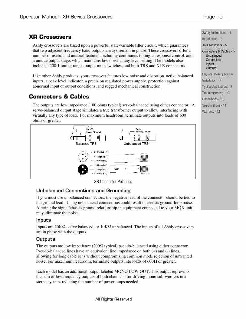
Connectors & CablesThe outputs are low impedance (100 ohms typical) servo-balanced using either connector. Aservo-balanced output stage simulates a true transformer output to allow interfacing withvirtually any type of load. For maximum headroom, terminate outputs into loads of 600ohms or greater.
XR Connector Polarities
Unbalanced Connections and GroundingIf you must use unbalanced connectors, the negative lead of the connector should be tied tothe ground lead. Using unbalanced connections could result in chassis ground-loop noise.Altering the signal/chassis ground relationship in equipment connected to your MQX unitmay eliminate the noise.
InputsInputs are 20K active balanced, or 10K unbalanced. The inputs of all Ashly crossoversare in phase with the outputs.
OutputsThe outputs are low impedance (200 typical) pseudo-balanced using either connector.Pseudo-balanced lines have an equivalent line impedance on both (+) and (-) lines,allowing for long cable runs without compromising common mode rejection of unwantednoise. For maximum headroom, terminate outputs into loads of 600 or greater.
Each model has an additional output labeled MONO LOW OUT. This output representsthe sum of low frequency outputs of both channels, for driving mono sub-woofers in astereo system, reducing the number of power amps needed.
Safety Instructions – 3
Introduction – 4
XR Crossovers – 5
Connectors & Cables – 5Unbalanced
ConnectorsInputsOutputs
Physical Description - 6
Installation – 7
Typical Applications - 8
Troubleshooting - 10
Dimensions - 10
Specifications - 11
Warranty - 12

Page - 6 Operator Manual – XR Series Crossovers
Copyright© 2006 – Ashly Audio Inc.
Physical DescriptionThe XR-1001 is 1RU, and weighs 8 pounds. The XR-2001 & XR-4001 are 2RU, and weigh 11 pounds.
XR-1001 & XR-4001 Front Panels
1. Power - There is a dedicated power LED on the front;the power switch is on the back of the unit.
2. Input Level - boosts incoming signal up to +8dBbefore it reaches the filters, or attenuates the signal tooff. Maximum input level is +23dBu. The “U” shown atthe 12:00 position indicates “unity gain.”
3. Crossover Frequency - This infinitely variable controlallows you to select an appropriate crossover point.Clockwise turning raises the crossover frequencywhile counterclockwise lowers it. Frequencies aremarked on standard ISO 1/3 octave centerfrequencies with each octave calibrated. Calibrationaccuracy is typically within 1/3 octave or better. Ifgreater accuracy is necessary, measure the actualcrossover frequency with an external device.
To allow a wider tuning range, the crossovers use arecessed range switch for each frequency control.LED indicators provide range status at power-on. Therange switch divides the frequency indicated on thefrequency control by 10 and gives a total range of200:1. Avoid damage to speakers by muting theoutputs before changing the range switch.
4. Response - adjusts the damping of the filter affectingthe response shape at the crossover point. The dialcalibrations refer to the amount of attenuation effectedby the filter at the crossover frequency, i.e., a settingof 3dB means that the filter’s high-pass and low-passoutputs are each “rolled off 3dB at the crossoverpoint”. This describes Butterworth filter response, or a
gentle 3dB peak at the crossover point where the twofilter output signals overlap. To obtain a flat signal, or“Linkwitz-Riley” response, set the Response control to“6”. To obtain a notch at the crossover point, turndown the response control past “6” to best suit yourneeds. The purpose of this control is to help offset theinaccuracies inherent in typical loudspeakers, helpingyou to achieve a flat system response. NOTE: TheResponse control is not a “slope” control. TheResponse control only affects filter response shape inthe immediate vicinity of the crossover frequency; theultimate crossover slope is a fixed parameter.
5. Output Level - The output stage operates at unity gain withthe output level controls set at “U”. Max gain of the outputstage is +15dB. In a typical setup, power amplifier inputlevel controls should be run “full-on”, with level control beingaccomplished at the crossover. Note that horn andcompression driver combinations are much more efficientthan cone speakers, often by 12 to 20dB. When usedtogether, you should expect a much lower level setting forthe horns to obtain proper balance. Output mute switchesallow you to isolate individual or grouped outputs forlistening tests without affecting the settings of any otheroutputs.
6. Clip Indicator - Ashly crossovers feature a peak detectionwhich monitors signal level at several critical points. TheLED will flash when signal levels of +20dBu are reachedanywhere in the crossover. Since our crossovers have anominal 23dB of headroom referenced to a standardoperating level of 0dBu (.77 Volts), a flashing LED warnsyou that you are only 3dB from clipping. Since peak levelsare monitored at several points, the clip LED can be used toisolate the source. If the LED flashes even though all inputand output levels are turned down, the signal feed isexcessive. If the LED flashes when you turn the Input levelcontrol up (with the outputs still turned down), the overloadis occurring in the filter sections, and you should back theInput level down a bit. If the LED first flashes when you turnthe output level controls up, then the overload is occurringin the output stage. In this case, if your power amplifiercontrols are at full gain, you are probably severelyoverdriving your amplifier.
Safety Instructions – 3
Introduction – 4
XR Crossovers – 5
Connectors & Cables–5
Physical Description – 6Front PanelsRear Panels
Installation – 7
Typical Applications - 8
Troubleshooting - 10
Dimensions - 10
Specifications - 11
Warranty - 12
CAUTION: High frequencycompression drivers may bedestroyed by the use of too lowa crossover frequency. Makesure the range switch isproperly set. You may want toinstall a security cover if theunit is accessible to untrainedpeople.
Operator Manual –XR Series Crossovers Page - 7
All Rights Reserved
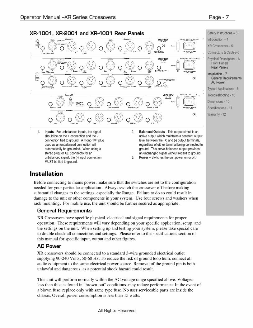
XR-1001, XR-2001 and XR-4001 Rear Panels
1. Inputs - For unbalanced inputs, the signalshould be on the + connection and the -connection tied to ground. A mono 1/4” plugused as an unbalanced connection willautomatically be grounded. When using astereo plug, or XLR connecto for anunbalanced signal, the (-) input connectionMUST be tied to ground.
2. Balanced Outputs - This output circuit is anactive output which maintains a constant outputlevel between the (+) and (-) output terminals,regardless of either terminal being connected toground. This servo-balanced output providesan unchanged signal without regard to ground.
3. Power – Switches the unit power on or off.
InstallationBefore connecting to mains power, make sure that the switches are set to the configurationneeded for your particular application. Always switch the crossover off before makingsubstantial changes to the settings, especially the Range. Failure to do so could result indamage to the unit or other components in your system. Use four screws and washers whenrack mounting. For mobile use, the unit should be further secured as appropriate.
General RequirementsXR Crossovers have specific physical, electrical and signal requirements for properoperation. These requirements will vary depending on your specific application, setup, andthe settings on the unit. When setting up and testing your system, please take special careto double check all connections and settings. Please refer to the specifications section ofthis manual for specific input, output and other figures.
AC PowerXR crossovers should be connected to a standard 3-wire grounded electrical outletsupplying 90-240 Volts, 50-60 Hz. To reduce the risk of ground loop hum, connect allaudio equipment to the same electrical power source. Removal of the ground pin is bothunlawful and dangerous, as a potential shock hazard could result.
This unit will perform normally within the AC voltage range specified above. Voltagesless than this, as found in “brown-out” conditions, may reduce performance. In the event ofa blown fuse, replace only with same type fuse. No user serviceable parts are inside thechassis. Overall power consumption is less than 15 watts.
Safety Instructions – 3
Introduction – 4
XR Crossovers – 5
Connectors & Cables–5
Physical Description – 6Front PanelsRear Panels
Installation – 7General RequirementsAC Power
Typical Applications - 8
Troubleshooting - 10
Dimensions - 10
Specifications - 11
Warranty - 12

Page - 8 Operator Manual – XR Series Crossovers
Copyright© 2006 – Ashly Audio Inc.
Typical ApplicationsThe following information will help you make the most of your new crossover:
Connecting to a Sound SystemUsually, the output signal from a final processing source such as a limiter or equalizer isfed to a crossover input and each crossover output feeds a power amplifier channel.Sometimes limiters are used on each crossover output to provide more accurate protection.
Speaker PlacementTo obtain maximum benefit from your crossover, a correctly assembled speaker array is anecessity. Low frequency speakers should be grouped as closely together as possible and midand high frequency drivers should be stacked vertically. This arrangement produces a tightvertical pattern, with wide horizontal dispersion free from high frequency lobing. If possible,speakers in the array should be arranged so the drivers are equal distance from the listener.
XR 1001 Stereo 2-Way or Mono 3-Way Operation
XR1001This product functions as either a stereo 2-way or mono 3-way crossover. Mono 3-way isselected by depressing the MODE switch and using the appropriate connectors andcontrols.
Safety Instructions – 3
Introduction – 4
XR Crossovers – 5
Connectors & Cables–5
Physical Description – 6
Installation – 7
Typical Applications – 8ConnectingSpeaker PlacementXR1001 OperationXR2001 OperationXR4001 Operation
Troubleshooting - 10
Dimensions - 10
Specifications - 11
Warranty - 12

Operator Manual –XR Series Crossovers Page - 9
All Rights Reserved
XR 2001 Mono 4-Way or Mono 5-Way Operation
XR2001The XR 2001 functions as a four channel 2-way, stereo 3-way, mono 4-way, or mono 5-way. For mono 4-way or mono 5-way operation, cascade a low output (set up as a mid in a4-way or 5-way) to the next channel's input, setting the matched output and input levelcontrols to unity gain.
XR4001The XR4001 is a stereo 4-way crossover. If desirable, you can cascade the low output ofone channel into the input of the other, similar to XR2001 in mono 5-way mode. Thisconfiguration results in a mono 5-way with tunable lowpass and hipass filters to protectagainst unwanted subsonic/ultrasonic signals. When using the mono low output, rememberthat both channels contribute to the signal, and should be set equally.
Safety Instructions – 3
Introduction – 4
XR Crossovers – 5
Connectors & Cables–5
Physical Description – 6
Installation – 7
Typical Applications – 8ConnectingSpeaker PlacementXR1001 OperationXR2001 OperationXR4001 Operation
Troubleshooting - 10
Dimensions - 10
Specifications - 11
Warranty - 12

Page - 10 Operator Manual – XR Series Crossovers
Copyright© 2006 – Ashly Audio Inc.
TroubleshootingSituation ActionNo Output Check AC power - is LED indicator on? Check in/out connections, are they reversed? Are
you sure you have input signal?
Peak light flashesfrequently
The level is too high somewhere in the crossover. Try turning down individual output levelsand then the input until the peak LED stays off. If the peak LED continues to flash when all ofthe crossover level controls are turned down, then the crossover is being fed excessivelyhigh levels from a previous piece of equipment. Turn down your driving source.
Distorted sound Is the peak light flashing? If it is, an overload is occurring within the crossover, and may alsobe occurring in other parts of the system. If the peak light is not flashing, the distortion isoccurring somewhere outside the crossover.
Excessive hum or noise Hum will usually be caused by a “ground loop” between components. Try using thesuggested balanced input and output hookups if the other pieces of equipment used inconjunction with your crossover have balanced inputs and outputs. Noise can be caused byinsufficient drive signal. Ashly crossovers provide the best noise and headroom performancewhen the input signal is 0 to +4dBu level and power amplifier sensitivity is higher than 1 volt.Unshielded cables, improperly wired connections, and cable with broken strands (shorts,etc.) are the most common problems. Please properly maintain and inspect your wiring first.
Note: Unshielded cables, improperly wired connections, and cable with broken strands(shorts, etc.) are the most common problems. Make sure you use good quality cable withconnectors soldered firmly on the correct pin. When in doubt, get in touch with your Ashlydealer.
Dimensions
Safety Instructions – 3
Introduction – 4
XR Crossovers – 5
Connectors & Cables–5
Physical Description – 6
Installation – 7
Typical Applications – 8
Troubleshooting - 10
Dimensions - 10
Specifications - 11
Warranty - 12

Operator Manual –XR Series Crossovers Page - 11
All Rights Reserved
SpecificationsSpecification XR 1001 XR 2001 XR 4001
Input Level Control - to +8.5 dB - to +8.5 dB - to +8.5 dB
Damping/Response 2dB – 12dB 2dB – 12dB 2dB – 12dB
Output Level Control - to +15 dB - to +15 dB - to +15 dB
Input Impedance 20K Balanced 20K Balanced 20K Balanced
Output Impedance 100 Servo Balanced 100 Servo Balanced 100 Servo Balanced
Maximum Input Level +23 dBu +23 dBu +23 dBu
Maximum Output Level +23 dBu +23 dBu +23 dBu
Frequency Response ±0.5dB 20Hz-20kHz ±0.5dB 20Hz-20kHz ±0.5dB 20Hz-20kHz
Distortion<0.05% THD (+10 dBu 20 Hz-
20kHz)<0.05% THD (+10 dBu 20 Hz-
20kHz)<0.05% THD (+10 dBu 20 Hz-
20kHz)
Slew Rate 6V/μS 6V/μS 6V/μS
Hum and Noise <-95dBu unweighted 20 Hz-20kHz <-95dBu unweighted 20 Hz-20kHz <-95dBu unweighted 20 Hz-20kHz
Power Requirements100-240 VAC 50-60 Hz
24 Watts100-240 VAC 50-60 Hz
24 Watts100-240 VAC 50-60 Hz
24 Watts
Shipping Weight 13 lbs 16 lbs 16 lbs
Dimensions 19”Lx1.75”Hx8”D 19”Lx3.5”Hx8”D 19”Lx3.5”Hx8”D
Safety Instructions – 3
Introduction – 4
XR Crossovers – 5
Connectors & Cables–5
Physical Description – 6
Installation – 7
Typical Applications – 8
Troubleshooting - 10
Dimensions - 10
Specifications - 11
Warranty - 12

Page - 12 Operator Manual – XR Series Crossovers
Copyright© 2006 – Ashly Audio Inc.
Limited WarrantyWarranty service for this unit will be provided by ASHLY AUDIO INC. in accordance withthe following warrant statement.
ASHLY AUDIO INC. warrants to the owner of this product that this product and thecomponents thereof, will be free from defects in workmanship and materials for a period ofFIVE years from the date of purchase. ASHLY AUDIO INC. (ASHLY AUDIO) will,without charge, repair or replace, at its option, defective product or component parts uponprepaid delivery to the factory service department or authorized service center, accompaniedby proof of purchase date in the form of a valid sales receipt. This warranty gives youspecific legal rights, and you may also have other rights which vary from state to state.
EXCLUSIONS: This warranty does not apply in the event of misuse, neglect or as a result ofunauthorized alterations or repairs. This warranty is void if the serial number is altered,defaced, or removed. ASHLY AUDIO reserves the right to make changes in design or makeadditions to or improvements upon this product without any obligation to install the same onproducts previously manufactured.
Any implied warranties which may arise under the operation of State law shall be effectiveonly for FIVE years from the date of purchase of the product. Ashly Audio shall be liable onlyto correct defects in the product itself, and not for any damage or injury which may result fromor be incidental to or a consequence of such defect. Some states do not allow either limitationson how long an implied warranty lasts, or the exclusion or limitation of incidental orconsequential damages, so the above limitations or exclusions may not apply to you.
Obtaining Warranty Service in the United StatesFor warranty service in the United States, please follow this procedure:
Return the product to Ashly, freight prepaid, with a written statement describing the defectand application the product is used in. Ashly Audio will examine the product and performany necessary service, including replacement of defective parts, at no further cost to you.
Ship your product to:Ashly Audio Inc.Attn: Service Department847 Holt RoadWebster, NY 14580-9103
For units purchased outside The United States of America, service will be provided by anauthorized distributor of ASHLY AUDIO INC.
Obtaining Warranty Service Outside the United States For units purchased outside TheUnited States of America, service will be provided by an authorized distributor of ASHLYAUDIO INC.
Safety Instructions – 3
Introduction – 4
XR Crossovers – 5
Connectors & Cables–5
Physical Description – 6
Installation – 7
Typical Applications – 8
Troubleshooting - 10
Dimensions - 10
Specifications - 11
Warranty - 12

Operator Manual –XR Series Crossovers Page - 13
All Rights Reserved