ashrae standards 62.1 and 90.1 and vav systems - trane · pdf filein this broadcast, the chair...
TRANSCRIPT

engineers newsletter live Course Outline
ASHRAE Standards 62.1 and 90.1 and VAV Systems These days many designers want to comply with both Standard 62.1 and Standard 90.1. Requirements from both standards have been incorporated into many building codes, and the minimum requirements of both standards must be met as prerequisites to LEED certification. In attempting to comply with the ventilation requirements of Standard 62.1 AND the energy-limiting requirements of Standard 90.1, some designers have concluded that it’s next to impossible to do so using traditional VAV systems. While in some specific cases these designers might be right, in most cases they are not right. In this broadcast, the Chair of SSPC 62.1 (Dennis Stanke), the Chair of SSPC 90.1 (Mick Schwedler), and the primary author of the HVAC sections in the User Manuals for both standards (Steve Taylor), discuss the potentially conflicting requirements and design choices. By attending this event you will learn: 1. Key VAV system requirements found in both standards 2. How to avoid the potential conflict between the central reheat restrictions of Standard 90.1 and
dehumidification requirements of Standard 62.1 3. How to choose VAV box minimum airflow settings to avoid the potential conflict between the
local reheat restrictions of and the minimum ventilation at all loads 4. How implement zone-level demand controlled ventilation to save energy while maintaining
minimum ventilation Program Outline: 1) Overview – Why are the standards important and why must they comply? 2) DCV
a) 62.1 b) 90.1 c) Conflicts? d) How do you comply?
3) Dehumidification a) 62.1 b) 90.1 c) Conflicts? d) How do you comply?
4) Simultaneous heating and cooling a) 90.1 (2004 and 2007) b) 62.1 (2004 and 2007) c) Conflicts? d) How do you comply?
© Trane, a business of Ingersoll Rand 1

engineers newsletter live Presenter Biographies
ASHRAE Standards 62.1 and 90.1 and VAV Systems
Steve Taylor | principal | Taylor Engineering
Steve Taylor is the principal of Taylor Engineering, Alameda, CA. He is a registered mechanical engineer specializing in HVAC system design, control system design, indoor air quality engineering, computerized building energy analysis, and HVAC system commissioning. Mr. Taylor graduated from Stanford University with a BS in Physics and a MS in Mechanical Engineering and has over 30 years of commercial HVAC system design and construction experience. He was the primary author of the HVAC sections of ASHRAE Standard 90.1-1989 and 1999 “Energy Conservation in New Non-residential Buildings” and California’s Title 24 Energy Standards and Ventilation Standards. Other ASHRAE project and technical committees Mr. Taylor has participated in include Standard 62.1 Indoor Air Quality (chair), ASHRAE Standard 55 Thermal Comfort (member), Guideline 13 Specifying DDC (chair), Guideline 16 Economizer Dampers (chair), TC 1.4 Controls (chair), and TC 4.3 Ventilation (vice-chair).
Dennis Stanke | staff applications engineer | Trane
With a BSME from the University of Wisconsin, Dennis joined Trane in 1973 as a controls development engineer. He is now a Staff Applications Engineer specializing in airside systems including controls, ventilation, indoor air quality, and dehumidification. He has written numerous applications manuals and newsletters, has published many technical articles and columns, and has appeared in many Trane Engineers Newsletter Live broadcasts. An ASHRAE Fellow, he is currently Chairman for SSPC62.1, the ASHRAE committee responsible for Standard 62.1, “Ventilation for Acceptable Indoor Air Quality,” and he serves on the USGBC LEED Technical Advisory Group for Indoor Environmental Quality (the LEED EQ TAG).
Mick Schwedler | manager, applications engineering | Trane
Mick has been involved in the development, training, and support of mechanical systems for Trane since 1982. With expertise in system optimization and control (in which he holds patents), and in chilled-water system design, Mick’s primary responsibility is to help designers properly apply Trane products and systems. To do so, he provides one-on-one support, writes technical publications, and presents seminars. To date, he has reached audiences throughout North America and in South America and the Far East.
A recipient of ASHRAE’s Distinguished Service Award, Mick is Chair of SSPC 90.1, which was responsible for writing ANSI/ASHRAE/IESNA 90.1-2007, a prerequisite for LEED. He also contributed to the ASHRAE GreenGuide and is a member of the LEED Energy and Atmospheric Technical Advisory Group (TAG). Mick earned his mechanical engineering degree from Northwestern University and holds a master’s degree from the University of Wisconsin Solar Energy Laboratory. He also is a registered professional engineer in the State of Wisconsin.
© Trane, a business of Ingersoll Rand 2

© 2008 Trane
ASHRAE Standards 62.1 and 90.1 and VAV Systems
anEngineers Newsletter Live telecast
© 2008 Trane
“Trane” is a Registered Provider with The American Instituteof Architects Continuing Education Systems. Credit earned on completion of this program will be reported to CES Records for AIA members. Certificates of Completion for non-AIA members available on request.
This program is registered with the AIA/CES for continuing professional education. As such, it does not include content that may be deemed or construed to be an approval or endorsement by the AIA of any material of construction or any method or manner of handling, using, distributing, ordealing in any material or product.Questions related to specific materials,methods, and services will be addressedat the conclusion of this presentation.
© Trane, a business of Ingersoll Rand 3

© 2008 Trane
ASHRAE Standards 62.1 and 90.1 and VAV Systems
Agenda Demand-controlled ventilation
Dehumidification
Simultaneous heating and cooling
Questions
Summary
© 2008 Trane
Today’s Presenters
Dennis Stankestaff applicationsengineer
Mick Schwedlermanager,applications engineering
Steve Taylorprincipal,Taylor Engineering
© Trane, a business of Ingersoll Rand 4

© 2008 Trane
DemandDemand--controlled controlled ventilationventilation
ASHRAE Standards 62.1 and 90.1 and VAV Systems
© 2008 Trane
Std 62.1-2007 Requirements
Areas of potential conflict with Standard 90.1 requirements Ventilation control or dynamic reset
options (DCV for zones, VRC for systems)
Dehumidification requirements (65% RH analytical limit)
Zone minimum airflow in VAV-reheat systems (intake airflow depends on zone airflow)
© Trane, a business of Ingersoll Rand 5

© 2008 Trane
std 62.1-2007 section 6.2.7Dynamic ResetOptional controls may reset zone or intake airflow in response to changing conditions, e.g.: Variations in zone occupancy, based on TOD
schedule, direct count of occupants, or outdoor air rate per person based on sensed CO2
Variations in system ventilation efficiency based on system airflow values
Variations in VAV box minimums due to changes in system outdoor air intake flow (when economizing)
© 2008 Trane
dynamic resetOperation As Conditions VaryFor this presentation,
“Demand controlled ventilation” (DCV) resets zone outdoor airflow (Voz) as zone population or effective OA per person varies (zone-levelcontrol)
“Ventilation reset control” (VRC) resets outdoor air intake flow (Vot) in multiple-zone systems as system ventilation efficiency (Ev) varies (system-level control)
“Ventilation optimization” combines DCV and VRC for multiple-zone (VAV) systems
© Trane, a business of Ingersoll Rand 6

© 2008 Trane
std 62.1-2007 section 6.2.2Zone Calculations1. Calculate breathing-zone outdoor airflow, using
Table 6-1 rates (cfm/per, cfm/ft2)Vbz = Rp × Pz + Ra × Az
2. Determine zone air distribution effectiveness, EzLook up Ez (typically 1.0) (Table 6-2)
3. Calculate zone outdoor airflowVoz = Vbz/Ez
© 2008 Trane
dynamic resetZone-Level DCV Approaches TOD: Determine Voz using effective population,
Pz’, based on time-of-day schedule
OCC: Determine Voz using Pz’ equal to design or zero population, based on occupancy sensors
COU: Determine Voz using Pz’ equal to actual population, based on direct count
Voz=(Rp*Pz’+Ra*Az)/Ez
Rp’ = N/(Cr – Co)where N = CO2 cfm/person
CO2: Maintain effective “people outdoor air rate”Rp’, in breathing zone, based on differential CO2
© Trane, a business of Ingersoll Rand 7

© 2008 Trane
dynamic resetOperation As Conditions Vary
For this presentation, “Demand controlled ventilation” (DCV) resets
zone outdoor airflow (Voz) as zone population or effective OA per person varies (zone-level control)
“Ventilation reset control” (VRC) resets outdoor air intake flow (Vot) in multiple-zone systems as system ventilation efficiency (Ev) varies (system-level control)
“Ventilation optimization” combines DCV and VRC for multiple-zone (VAV) systems
© 2008 Trane
std 62.1 section 6.2.5Multiple-Zone SystemsCan’t deliver OA with 100% efficiency because some excess OA exhausts
zone 1OVER-VENTILATED
zone 3OVER-VENTILATED
zone 2PROPERLYVENTILATED
VAV
Some excess(unused) OA
leaves building
PA
OAVAVair handler
RA
VAV
PA RA
VAV
PA RA
EA RA
© Trane, a business of Ingersoll Rand 8

© 2008 Trane
6.2.5 Multiple-Zone Recirculating SystemsWhen one air handler supplies mixed air to many zones (e.g., VAV systems), find outdoor air intake flow (Vot) using prescribed equations:
Vot = Vou/Ev
Vou = f(Vbz in all zones)
Ev = 1 + Xs – Zd
Xs = Vou/Vps
Zd = Voz/Vdz
1
32
4
std 62.1 section 6.2.5System Calculations
© 2008 Trane
system calculationsVentilation Reset Control Current zone requirements
Vbz = breathing zone OA flow = (entry)Ez = air distribution eff. = (entry)Voz = zone outdoor airflow = Vbz/EzVdz = current discharge airflow = (measured)Zd = discharge OA fraction = Voz/Vdz
Current system requirementsVou = uncorrected OA flow = VbzXs = average OA fraction = Vou/VdzEvz = zone vent. efficiency = 1 + Xs – ZdEv = system vent. efficiency = smallest (Evz)Vot = outdoor air intake flow = Vou/Ev
© Trane, a business of Ingersoll Rand 9

© 2008 Trane
ventilation reset controlSingle-Duct VAV System
100% system load
Ventilation Reset Control reduces Vot
8, 810
Votw/ventreset
disc airflow Vdz 4,000 4,100 4,200 4,300 300 1,300vent rate Vbz 1,880 1,880 2,190 2,190 85 760vent fraction Zdz 0.470 0.459 0.521 0. 509 0.283 0.585Vou = 6,500Xs = Vou/Vps = 6,500/18,200 = 0.357Ev = 1 + 0.357 – 0.585 = 0.772Vot = Vou/Ev = 6,500/0.772 = 8,410
90% system load8,810
Votreq’d
@ design
8,810
8,410
disc airflow Vdz 4,960 5,400 4,000 4,000 500 1,300vent rate Vbz 1,880 1,880 2,190 2,190 85 760vent fraction Zdz 0.379 0.348 0.548 0.548 0.170 0.585Vou = D*Rp*Pz + Ra*Az = 0.65*7,125 + 1860 = 6,500Xs = Vou/Vps = 6,500/20,160 = 0.322Ev = 1 + 0.322 – 0.585 = 0.738Vot = Vou/Ev = 6,500/0.738 = 8,808
w/
VR
C
w/
o V
RC
© 2008 Trane
dynamic resetOperation As Conditions Vary
For this presentation, “Demand controlled ventilation” (DCV) resets
zone outdoor airflow (Voz) as zone population or effective OA per person varies (zone-levelcontrol)
“Ventilation reset control” (VRC) resets outdoor air intake flow (Vot) in multiple-zone systems as system ventilation efficiency (Ev) varies (system-level control)
“Ventilation optimization” combines DCV and VRC for multiple-zone (VAV) systems
© Trane, a business of Ingersoll Rand 10
© 2008 Trane
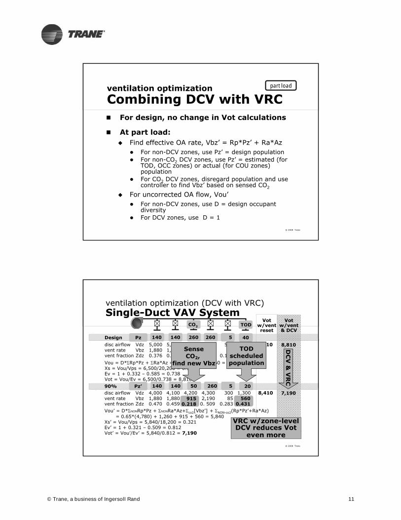
ventilation optimizationCombining DCV with VRC For design, no change in Vot calculations
At part load: Find effective OA rate, Vbz’ = Rp*Pz’ + Ra*Az
For non-DCV zones, use Pz’ = design population For non-CO2 DCV zones, use Pz’ = estimated (for
TOD, OCC zones) or actual (for COU zones) population
For CO2 DCV zones, disregard population and use controller to find Vbz’ based on sensed CO2
For uncorrected OA flow, Vou’ For non-DCV zones, use D = design occupant
diversity For DCV zones, use D = 1
part load
© 2008 Trane
ventilation optimization (DCV with VRC)Single-Duct VAV System
disc airflow Vdz 5,000 5,400 4,000 4,000 500 1,300vent rate Vbz 1,880 1,880 2,190 2,190 85 760vent fraction Zdz 0.376 0.351 0.548 0.548 0.170 0.585Vou = D*Rp*Pz + Ra*Az = 0.65*7,130 + 1860 = 6,500Xs = Vou/Vps = 6,500/20,200 = 0.332Ev = 1 + 0.332 – 0.585 = 0.738Vot = Vou/Ev = 6,500/0.738 = 8,810
Design8,810
8,410
CO2 TOD
260140 140 260 5 408,810
Votw/vent& DCV
7,190
Votw/ventreset
Pz
90% 260140 140 50 5 20Pz’disc airflow Vdz 4,000 4,100 4,200 4,300 300 1,300vent rate Vbz 1,880 1,880 2,190 2,190 85 680vent fraction Zdz 0.470 0.459 0.146 0. 509 0.283 0.431Vou’ = D*NONRp*Pz + NONRa*Az+co2[Vbz’] + NON-co2(Rp*Pz’+Ra*Az)
= 0.65*(4,780) + 1,260 + 915 + 560 = 5,840Xs’ = Vou/Vps = 5,840/18,200 = 0.321Ev’ = 1 + 0.321 – 0.509 = 0.812Vot’ = Vou’/Ev’ = 5,840/0.812 = 7,190
5600.431
9150.218
SenseCO2,
find new Vbz
TODscheduledpopulation
DC
V &
VR
C
VRC w/zone-level DCV reduces Vot
even more
© Trane, a business of Ingersoll Rand 11

© 2008 Trane
90.1 Requirements –Demand-Controlled ventilation
ASHRAE Standards 62.1 and 90.1 and VAV Systems
© 2008 Trane
ventilation optimization
Zone Level: DCV
lounge restroom
storage office
office conference rm computer roomreception area elev
ator
s
vestibule corridor
CO2
CO2
mechroom
OCC
OCCAHU
BAS
TOD TOD
© Trane, a business of Ingersoll Rand 12
© 2008 Trane
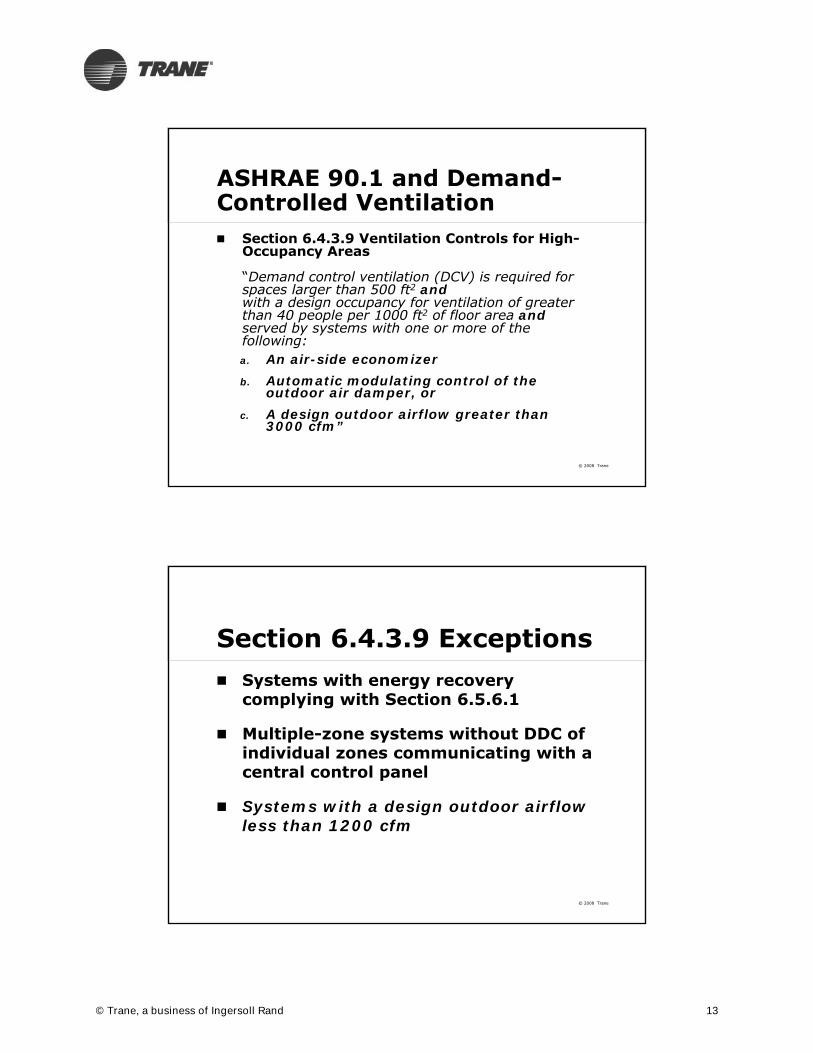
ASHRAE 90.1 and Demand-Controlled Ventilation Section 6.4.3.9 Ventilation Controls for High-
Occupancy Areas
“Demand control ventilation (DCV) is required for spaces larger than 500 ft2 andwith a design occupancy for ventilation of greater than 40 people per 1000 ft2 of floor area andserved by systems with one or more of the following:a. An air-side economizerb. Automatic modulating control of the
outdoor air damper, orc. A design outdoor airflow greater than
3000 cfm”
© 2008 Trane
Section 6.4.3.9 Exceptions Systems with energy recovery
complying with Section 6.5.6.1
Multiple-zone systems without DDC of individual zones communicating with a central control panel
Systems with a design outdoor airflow less than 1200 cfm
© Trane, a business of Ingersoll Rand 13

© 2008 Trane
To What Types of Spaces Might 6.4.3.9 Apply?
High Occupancy Lecture hall, assembly, cafeteria, lobbies
Most likely requirement to apply? >3,000 cfm of outdoor air or
outdoor air economizer
Most likely exception? < 1,200 cfm of system outdoor air
© 2008 Trane
Cooling capacity for which an economizer is required
climate and system size determinantsEconomizers
Climate zone
1a, 1b, 2a, 3a, 4a Economizer unnecessary(Miami, St. Louis, Charlotte)
2b, 5a, 6a, 7, 8 ≥ 135,000 Btu/h(Yuma, Chicago, Edmonton)
3b, 3c, 4b, 4c, 5b, 5c, 6b ≥ 65,000 Btu/h(Denver, Lubbock, Vancouver)
© Trane, a business of Ingersoll Rand 14

© 2008 Trane
Advanced Energy Design Guides
Climate Zone Map
Required for Systems > 5T
Required for Systems > 11T
Marine Dry Moist
EconomizerNot Required
© 2008 Trane
Does 6.4.3.9 Apply to a Middle School Classroom? 62.1 defaults
35 people / 1000 ft2
Combined outdoor air rate 13 cfm/person
Default is < 40 people/1000 ft2
Ventilation controls not required
© Trane, a business of Ingersoll Rand 15

© 2008 Trane
DCV – Conflicts between Standards 62.1 and 90.1? There are no conflicts in theory
90.1 requires DCV for certain applications
62.1 allows DCV for any application
But specifics are lacking in both standards so demonstrating compliance is difficult
© 2008 Trane
DCV Techniques Not Well Defined Standard 90.1
Demand control ventilation (DCV): a ventilation system capability that provides for the automatic reduction of outdoor air intake below design rates when the actual occupancy of spaces served by the system is less than design occupancy.
© Trane, a business of Ingersoll Rand 16

© 2008 Trane
Standard 62.1 6.2.7 Dynamic Reset: the system may be designed
to reset the design outdoor air intake flow (Vot) and/or space or zone airflow as operating conditions change.
These conditions include but are not limited to:1. Variations in occupancy or ventilation airflow in one
or more individual zones for which ventilation airflow requirements will be reset.
Note: Examples of measures for estimating such variations include: occupancy scheduled by time-of-day, a direct count of occupants, or an estimate of occupancy or ventilation rate per person using occupancy sensors such as those based on indoor CO2 concentrations.
DCV Techniques Not Well Defined
© 2008 Trane
Standard 62.1 User’s Manual Appendix A: CO2-Based DCV
Equation to correlate CO2setpoints to OA rate derived from basic principals
z
zap
zOAR
PARR
mECC
8400
outdoor air
VI
ot3 COA
(Vpz – VI
ot), CRA
N, v, CR
VpzI, Cs
VI
ot3 CR
VI
ot3 CR
© Trane, a business of Ingersoll Rand 17

© 2008 Trane
Standard 62.1 User’s Manual Appendix A: CO2-Based DCV
Key assumptions: CO2 generation rate Is proportional to bioeffluent generation
rate
Is proportional to activity level and activity level is predictable
© 2008 Trane
CO2 Concentration and Ventilation Rate
z
zap
zOAR
PARR
mECC
8400
CR = room CO2 concentrationCOA = outdoor air CO2 concentrationEz = zone ventilation effectivenessRp = people componentRa = area or building componentAz = zone floor areaPz = design number of people m = activity level (met)
© Trane, a business of Ingersoll Rand 18

© 2008 Trane
Steady State CO2Concentration
Based on 400 ppm CO2outdoor air concentration
© 2008 Trane
Constant Volume Single Zone CO2 DCV Procedure Calculate the Vot at design occupancy
Using the same equations, calculate the outdoor air rate with no occupants (Vat)
Determine the steady-state CO2 concentration (CO2max)
Provide a CO2 sensor/relay adjusted to send Maximum output signal when room CO2 is at CO2max
Minimum output signal when room CO2 is ambient (400 ppm)
Adjust outdoor air damper actuator so that At maximum output signal, outdoor air rate = Vot At minimum output signal, outdoor air rate = Vat
© Trane, a business of Ingersoll Rand 19
© 2008 Trane
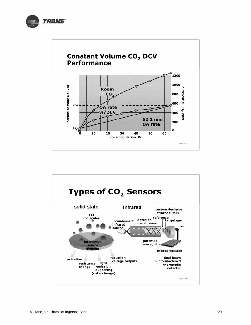
Constant Volume CO2 DCV Performance
10 20
Vat
Voz
zone population, Pz
bre
ath
ing
zo
ne
OA
, V
bz
30 40 50 60
diffe
ren
tial C
O2 , p
pm
200
400
600
800
1000
1200
00 0
62.1 min OA rate
Room CO2
OA rate w/DCV
© 2008 Trane
Types of CO2 Sensors
solid state infrared custom designedinfrared filters
incandescent infrared source
dual beam micro-machined
thermopile detector
patentedwaveguide
microprocessor
referencetarget gasdiffusion
membranes
oxidationresistance change
light emission quenching
(color change)
reduction(voltage output)
interactive sensor
element
gas molecules
© Trane, a business of Ingersoll Rand 20

© 2008 Trane
CO2 Sensor AccuracyNBCIP Product Test
CA Title 24 requirement
© 2008 Trane
Single Zone CO2 DCV Control Schematic
sensor in breathing
zone
zone CO2 sensor
signal converter
exhaust air
outdoorair
© Trane, a business of Ingersoll Rand 21

© 2008 Trane
CO2 DCV with Multiple Zone Systems
Exact technique for optimum energy usage and to ensure 62.1 compliance has not yet been determined
ASHRAE Research Project RP 1547 work statement being developed – results probably in late 2010
© 2008 Trane
CO2 DCV with Multiple Zone Systems
1) Increase zone airflow and reheat?
2) Increase minimum system OA and cooling (or heating) load?
On rise in space CO2what do you change? CO2
© Trane, a business of Ingersoll Rand 22

© 2008 Trane
Multiple Zone System CO2DCV One Approach (TBD by ASHRAE RP 1547)
Increase the zone damper up to 100% of zone maximum
Then stage the OA damper open from unoccupied minimum to design OA minimum
CO2 Signal
100%
0%
OA Minimum Setpoint
Zone Minimum Setpoint
© 2008 Trane
DehumidificationDehumidification
ASHRAE Standards 62.1 and 90.1 and VAV Systems
© Trane, a business of Ingersoll Rand 23

© 2008 Trane
Std 62.1-2007 Requirements
Areas of potential conflict with Standard 90.1 requirements Ventilation control or dynamic reset
options (DCV for zones, VRC for systems)
Dehumidification requirements (65% RH analytical limit)
Zone minimum airflow in VAV-reheat systems (intake airflow depends on zone airflow)
© 2008 Trane
std 62.1-2007 section 5.10Dehumidification Std 62.1-2007 limits space relative
humidity to 65% or less, analyzed at dew point design (design dew point, mean coincident dry bulb)
System type, configuration and controls impact ability to meet the Std 62.1 limit
© Trane, a business of Ingersoll Rand 24

© 2008 Trane
single-zone system
Basic Constant Volume
EA
RA
SAOA
space
MA
T
constant-speed fan
space temperature determines cooling capacityspace temperature determines cooling capacity
C
© 2008 Trane
180
160
140
120
100
80
60
40
20
0
hu
mid
ity ratio
, gra
ins/
lb o
f dry a
ir
11030 40 50 60 70 80 10090dry-bulb temperature, °F
85
80
75
70
65
60
5550
4540
3530
wet-b
ulb te
mper
ature
, °F
full loadOA 96°F DB,
76°F WB
MA 80.6°F DB
basic CV system
MA
full loadOASA 55.7°F DB
(1,500 cfm)
SARA
RA 74°F DB,52% RH
4.8 tons
colder warmer
drier
wetter
© Trane, a business of Ingersoll Rand 25

© 2008 Trane
180
160
140
120
100
80
60
40
20
0
hu
mid
ity ratio
, gra
ins/
lb o
f dry a
ir
11030 40 50 60 70 80 10090dry-bulb temperature, °F
85
80
75
70
65
60
5550
4540
3530
wet-b
ulb te
mper
ature
, °F
part loadOA 76°F DP,
84°F DB
part loadOA
MA 77°F DB
MA
SA 63°F DB(1,500 cfm)
SA
RA 74°F DB,52% RH
RA
RA'
full loadOA
basic CV system
65% RH
© 2008 Trane
180
160
140
120
100
80
60
40
20
0
hu
mid
ity ratio
, gra
ins/
lb o
f dry a
ir
11030 40 50 60 70 80 10090dry-bulb temperature, °F
85
80
75
70
65
60
5550
4540
3530
wet-b
ulb te
mper
ature
, °F
part loadOA
RA
MA
SA
RA
76°F DP,84°F DB
MA
77°F DB
SA
63°F DB(1,500 cfm)
compared compared to 52% at to 52% at full loadfull load
74°F DB,67% RH
full loadOA
part loadOA
basic CV system
3.7 tonscompared compared to 4.8 tons to 4.8 tons at full loadat full load
© Trane, a business of Ingersoll Rand 26

© 2008 Trane
100% outdoor air systemDedicated Outdoor Air
OA
direct tospaces
dedicatedOA unit
CA
CACA
RA RA
SA SA
© 2008 Trane
180
160
140
120
100
80
60
40
20
0
hu
mid
ity ratio
, gra
ins/
lb o
f dry a
ir
11030 40 50 60 70 80 10090dry-bulb temperature, °F
85
80
75
70
65
60
5550
4540
3530
wet-b
ulb te
mper
ature
, °F
100% OA system(“cold” air)76°F DP,
84°F DBOA
part load
part loadOA74°F DB,
50% RHRA
RA
CA
CA
52°F DB,52°F DP(450 cfm)
68°F DB(1,050 cfm)
SA
SA
RA'
© Trane, a business of Ingersoll Rand 27

© 2008 Trane
multiple-zone recirculating systemSingle-Path VAV
space
space
RA
OA SA
EA
MA T
T
T
variable-speed fan
© 2008 Trane
180
160
140
120
100
80
60
40
20
0
hu
mid
ity ratio
, gra
ins/
lb o
f dry a
ir
11030 40 50 60 70 80 10090dry-bulb temperature, °F
85
80
75
70
65
60
5550
4540
3530
compared tocompared to67% with 67% with basic CV systembasic CV system
part loadOA 76°F DP,
84°F DB
MA
RASA
multiple-zone VAV system
74°F DB,57% RH
RA
79°F DBMA55°F DB(900 cfm)
SA
part loadOA
© Trane, a business of Ingersoll Rand 28

© 2008 Trane
comparison of dehumidification in humid climate
Classroom Relative Humidity
basic CV system
+ total-energy recovery
+ mixed-air bypass
+ 2-speed fan
+ return-air bypass
+ reheat (direct)
100% OA (DOAS, direct)
VAV w/local reheat
52% 67% 73%
50% 65% 70%
52% 65% 68%
52% 60% 68%
52% 55% 60%
52% 55% 55%
50% 53% 55%
52% 57% 60%
watch out
not so good
not so good
works OK
works well
works well*
works well*
works well
commentpeak DB peak DP mild,rainysystem type
*Std 90.1 reheat rules applyStd 62.1 requires 65% RH or
less at peak DP
© 2008 Trane
6.5.2 Simultaneous Heating and Cooling Limitation
6.2.5.1 Zone Controls
6.2.5.3 Dehumidification
© Trane, a business of Ingersoll Rand 29

© 2008 Trane
section 6: HVACMandatory Provisions
SimplifiedApproach
Option (§6.3)
proposedHVAC design
90.1-compliantHVAC system
prescriptiverequirements
(§6.5)
Energy CostBudget Method
(ECB, §11)
(small buildings only)
mandatoryprovisions
(§6.4)
© 2008 Trane
prescriptive HVAC requirements90.1-2007 Section 6.5.2.3DehumidificationDehumidification
Prevent:
Reheating
Mixing of hot and cold airstreams
Heating and cooling the same airstream
© Trane, a business of Ingersoll Rand 30
© 2008 Trane
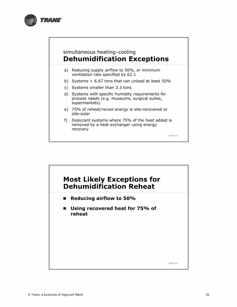
simultaneous heating–coolingDehumidification Exceptionsa) Reducing supply airflow to 50%, or minimum
ventilation rate specified by 62.1
b) Systems < 6.67 tons that can unload at least 50%
c) Systems smaller than 3.3 tons
d) Systems with specific humidity requirements for process needs (e.g. museums, surgical suites, supermarkets)
e) 75% of reheat/recool energy is site-recovered or site-solar
f) Desiccant systems where 75% of the heat added is removed by a heat exchanger using energy recovery
© 2008 Trane
Most Likely Exceptions for Dehumidification Reheat
Reducing airflow to 50%
Using recovered heat for 75% of reheat
© Trane, a business of Ingersoll Rand 31

© 2008 Trane
Dehumidification Conflicts between Standards 90.1 and 62.1?
No conflicts – compliance with both is possible
90.1 simply limits how dehumidification can be done to limit energy waste from simultaneous heating and cooling
© 2008 Trane
Compliance Techniques VAV Systems
Except in unusual applications with high space latent loads, humidity control is inherent
Limit supply air temperature reset upper limit
Dedicated OA Systems (DOAS) Any type of reheat is allowed by 90.1
Reheat using exhaust air sensible heat recovery or refrigerant hot gas
© Trane, a business of Ingersoll Rand 32

© 2008 Trane
Compliance Techniques Single zone systems
Reheat allowed for small units
Use variable speed or two-speed motors To be required for single zone systems ≥7.5 tons by Addendum 90.1n in 2012
Consider ECMs for small fan motors
Don’t oversize constant volume systems! Or: always use variable volume systems
© 2008 Trane
Single Zone VAVmaximum setpoint
supply air temperaturesetpoint
maximum speed
minimum speed
minimum setpoint
cooling loop signalheating loop signal
© Trane, a business of Ingersoll Rand 33

© 2008 Trane
Simultaneous Heating and Cooling
ASHRAE Standards 62.1 and 90.1 and VAV Systems
© 2008 Trane
prescriptive HVAC requirementsSection 6.2.5.1 Zone Controls
Zone controls No reheating
No recooling
No mixing or simultaneously supplying mechanically (or economizer) cooled and mechanically heated air
© Trane, a business of Ingersoll Rand 34

© 2008 Trane
simultaneous heating–coolingZone-Control Exceptionsa) Reduce zone airflow to
prescribed limit
b) Zones with special pressurization requirements or code-required minimum circulation rates
c) Site-recovered or site-solar energy provides ≥ 75% of reheat energy
© 2008 Trane
simultaneous heating–coolingZone-Control ExceptionsZone airflow does not exceed whichever
is largest:a) ASHRAE Standard 62’s zone
requirements for outdoor air
b) 0.4 cfm/ft²
© Trane, a business of Ingersoll Rand 35

© 2008 Trane
0
0.2
0.4
0.6
0.8
0 0.5 1 1.5 2 2.5
Room Airflow (cfm/ft2)
Reh
eat
Min
imu
m
Airflow at which Reheat is Allowed
© 2008 Trane
simultaneous heating–coolingZone-Control ExceptionsZone airflow does not exceed whichever is
largest:a) ASHRAE Standard 62’s zone
requirements for outdoor airb) 0.4 cfm/ft²c) 30% of supply aird) 300 cfme) ASHRAE Standard 62’s
multiple-space requirements,if approved by AHJ
© Trane, a business of Ingersoll Rand 36
© 2008 Trane
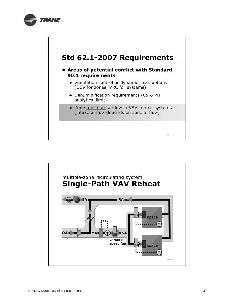
Std 62.1-2007 Requirements
Areas of potential conflict with Standard 90.1 requirements Ventilation control or dynamic reset options
(DCV for zones, VRC for systems)
Dehumidification requirements (65% RH analytical limit)
Zone minimum airflow in VAV-reheat systems (intake airflow depends on zone airflow)
© 2008 Trane
multiple-zone recirculating systemSingle-Path VAV Reheat
space
space
RA
OA SA
EA
MA T
T
T
variable-speed fan
© Trane, a business of Ingersoll Rand 37
© 2008 Trane
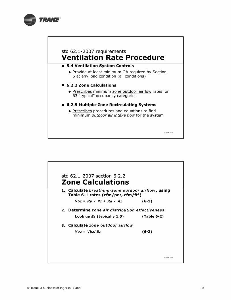
std 62.1-2007 requirementsVentilation Rate Procedure 5.4 Ventilation System Controls
Provide at least minimum OA required by Section 6 at any load condition (all conditions)
6.2.2 Zone Calculations Prescribes minimum zone outdoor airflow rates for
63 “typical” occupancy categories
6.2.5 Multiple-Zone Recirculating Systems Prescribes procedures and equations to find
minimum outdoor air intake flow for the system
© 2008 Trane
std 62.1-2007 section 6.2.2Zone Calculations1. Calculate breathing-zone outdoor airflow, using
Table 6-1 rates (cfm/per, cfm/ft2)Vbz = Rp × Pz + Ra × Az (6-1)
2. Determine zone air distribution effectivenessLook up Ez (typically 1.0) (Table 6-2)
3. Calculate zone outdoor airflowVoz = Vbz/Ez (6-2)
© Trane, a business of Ingersoll Rand 38

© 2008 Trane
std 62.1-2007 section 6.2.5Multiple-Zone Systems4. Find discharge outdoor air fraction (each zone)
Zd = Voz/Vdz (6-5)Vdz = Vdz-exp at condition analyzed
5. Find uncorrected outdoor airflowVou = D*(Rp×Pz) + (Ra×Az) (6-6)D = Ps/Pz
6. Find system ventilation efficiencyXs = Vou/Vps
Vps = Vps-exp at condition analyzed Evz = 1 + Xs – Zd (App A)Ev = lowest(Evz)
7. Find outdoor air intake flow:Vot = Vou/Ev (6-8)
© 2008 Trane
std 62.1-2007 section 6.2.5Multiple-Zone Systems Step 4 (find Zd = Voz/Vdz), use “minimum
expected” value (Vdz = Vdz-exp)
Potential conflict arises. Why? Designer must determine the minimum
primary airflow expected at the condition being analyzed for design purposes Is it the minimum zone outdoor airflow for
ventilation (Vdz-exp = Voz) per Std 62.1? Is it the “reheat-minimum” setting (Vdz-exp =
Vdz-rm) per Std 90.1, Exception a? Is it some other value (Vdz-exp ≥ Vdz-rm ≥Voz)?
© Trane, a business of Ingersoll Rand 39

© 2008 Trane
typical “single-supply” VAV-reheatPrimary* Airflow Minimums
cool primary airzone load design coolingdesign heating
dis
char
ge
airf
low
max clgairflow
deadband
max htgairflow
local reheatVoz
Vdz-clg
If Vdz-exp = Voz …Zd = Voz/Vdz-exp = 1.0Ev = 1 + Xs – Zd = XsVot = Vou/Xs = Vps
Questionabledesign:
100% OA
Vdz-rht
Vdz-exp
* Vpz = Vdz for single-supply systems
© 2008 Trane
cool primary air
dis
char
ge
airf
low
max clgairflow
deadband
max htgairflow
local reheatVoz
Vdz-rht
Vdz-clg
If Vdz-exp = Vdz-rm …Zd = Voz/Vdz-exp < 1.0Ev = 1 + Xs – Zd << 1.0Vot = Vou/Ev < Vps
Conservativedesign:
< 100% OA
Vdz-exp
zone load design coolingdesign heating* Vpz = Vdz for single-supply systems
typical “single-supply” VAV-reheatPrimary* Airflow Minimums
© Trane, a business of Ingersoll Rand 40

© 2008 Trane
cool primary air
dis
char
ge
airf
low
max clgairflow
deadband
max htgairflow
local reheatVoz
Vdz-rht
Vdz-exp
Vdz-clg
If Vdz-exp > Vdz-rm …Zd = Voz/Vdz-exp << 1.0Ev = 1 + Xs – Zd < 1.0Vot = Vou/Ev << Vps
Less conservative
design:<< 100% OA
zone load design coolingdesign heating* Vpz = Vdz for single-supply systems
typical “single-supply” VAV-reheatPrimary* Airflow Minimums
© 2008 Trane
Vdz-exp
cool primary air
dis
char
ge
airf
low
max clgairflow
deadband
max htgairflow
local reheatVoz
Vdz-clg
Vdz-rht
If Vdz-exp = Vdz-rm = Voz …Zd = Voz/Vdz-exp = 1.0Ev = 1 + Xs – Zd = XsVot = Vou/Xs = Vps
Using SFP box increases Vdz-exp:
< 100% OA
typical “single-supply” VAV-reheatPrimary* Airflow Minimums
zone load design coolingdesign heating* Vpz = Vdz for single-supply systems
© Trane, a business of Ingersoll Rand 41

© 2008 Trane
simultaneous heating and coolingConflicts between Standards 90.1 and 62.1? No conflicts – compliance with both is
possible
But some common VAV system design and control options will not work well Traditional single-duct VAV reheat systems
are limited
But VAV is still a viable option!
DOAS is not required and may not be the most efficient option!
© 2008 Trane
Compliance Techniques for VAV Systems
Use the Multiple Spaces Spreadsheet “62MZCalc” Model only realistic supply airflow scenarios
E.g. interior conference room will not be at minimum airflow if fully occupied
Include population diversity This can completely offset system inefficiency
compared to DOAS Provide transfer air (e.g. fan-powered boxes,
dual fan dual duct) to potentially critical zones Low or even zero VAV minimums are possible
© Trane, a business of Ingersoll Rand 42

© 2008 Trane
62MZCalc Spreadsheet
© 2008 Trane
62MZCalc Spreadsheet
© Trane, a business of Ingersoll Rand 43

© 2008 Trane
62MZCalc Spreadsheet
© 2008 Trane
62MZCalc Spreadsheet
© Trane, a business of Ingersoll Rand 44

© 2008 Trane
62MZCalc Spreadsheet
© 2008 Trane
VAV Reheat System – Heating Condition with 30% Minimums
© Trane, a business of Ingersoll Rand 45

© 2008 Trane
VAV Reheat System – Heating Condition with 30% Minimums
© 2008 Trane
VAV Reheat System – Heating Condition with 30%/0.4 cfm/ft2 Minimums
© Trane, a business of Ingersoll Rand 46

© 2008 Trane
VAV Reheat System – Heating Condition with 30%/0.4 cfm/ft2 Minimums
© 2008 Trane
Impact of Series Fan-Powered VAV Boxes
© Trane, a business of Ingersoll Rand 47

© 2008 Trane
Impact of Series Fan-Powered VAV Boxes
© 2008 Trane
Impact of Series Fan-Powered VAV Boxes
© Trane, a business of Ingersoll Rand 48

© 2008 Trane
Low Minimums Possible with Fan-Powered Boxes
© 2008 Trane
This concludes theAmerican Institute of Architects Continuing Education System Program
ASHRAE Standards 62.1 and 90.1 and VAV Systems
Answers toYour Questions
© Trane, a business of Ingersoll Rand 49
© 2008 Trane
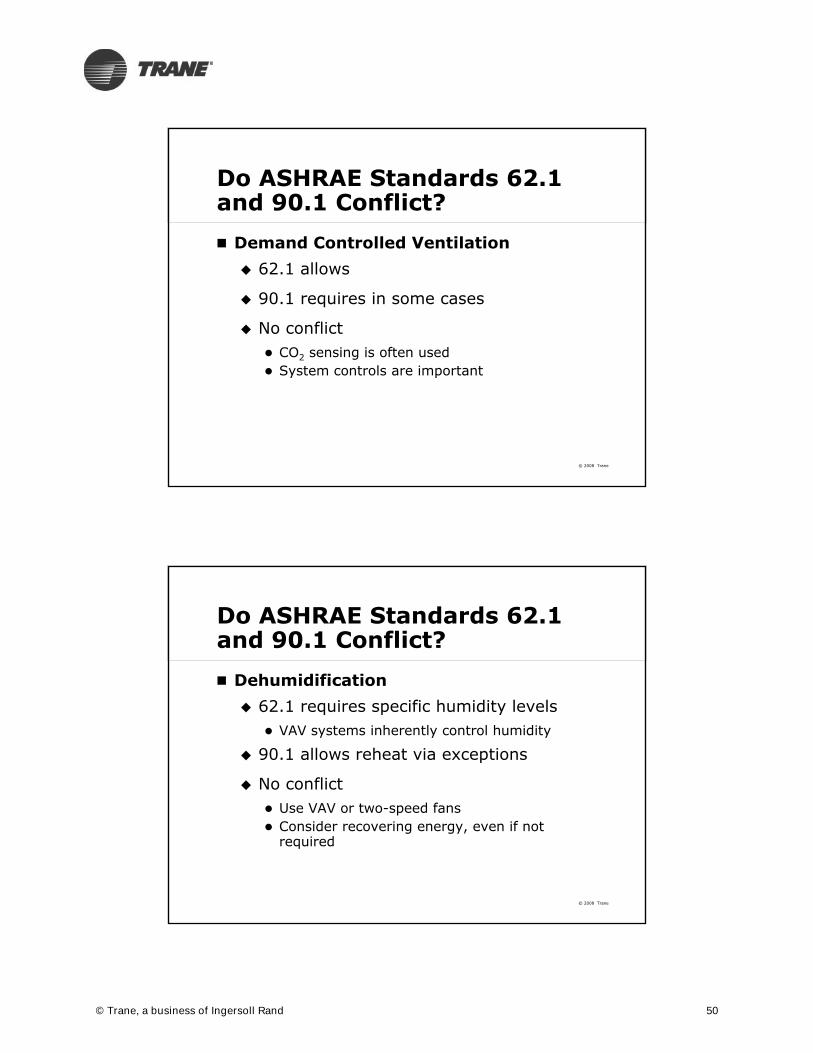
Do ASHRAE Standards 62.1 and 90.1 Conflict?
Demand Controlled Ventilation 62.1 allows
90.1 requires in some cases
No conflict CO2 sensing is often used System controls are important
© 2008 Trane
Do ASHRAE Standards 62.1 and 90.1 Conflict?
Dehumidification 62.1 requires specific humidity levels
VAV systems inherently control humidity
90.1 allows reheat via exceptions
No conflict Use VAV or two-speed fans Consider recovering energy, even if not
required
© Trane, a business of Ingersoll Rand 50

© 2008 Trane
Do ASHRAE Standards 62.1 and 90.1 Conflict?
Zone controls and reheat 90.1 requires reduction of zone airflows
prior to using new energy for reheat
62.1 requires specific ventilation airflows
No conflict, but… Challenges must be met through proper system
selection, design and operation
© 2008 Trane
references for this broadcast
Where to Learn More
www.trane.com/engineersnewsletterwww.trane.com/engineersnewsletter
© Trane, a business of Ingersoll Rand 51

© 2008 Trane
watch past broadcasts
ENL Archives
www.trane.com/bookstore
Insightful topics on HVAC system design:
Chilled-water plants
Air distribution
Refrigerant-to-air systems
Control strategies
Industry standards and LEED
Energy and the environment
Acoustics
Ventilation
Dehumidification
© 2008 Trane
2009 ENL Broadcasts March 11
LEED 2009 Modeling and Energy Savings
May 13Ice Storage System Design: Round-the-Clock Operation for Office Buildings and K-12 Schools
November 4 Air-Handling Systems, Energy, and IAQ
© Trane, a business of Ingersoll Rand 52

Trane Engineers Newsletter Live Program
Bibliography
Page 1 of 2
Industry Standards and Handbooks American Society of Heating, Refrigerating, and Air-Conditioning
Engineers (ASHRAE). ANSI/ASHRAE IESNA Standard 62.1-2007: Ventilation for Acceptable Indoor Air Quality. Available at www.ashrae.org/bookstore
American Society of Heating, Refrigerating, and Air-Conditioning Engineers (ASHRAE). ANSI/ASHRAE IESNA Standard 90.1-2004: Energy Standard for Buildings Except Low-Rise Residential Buildings. Available at Available at www.ashrae.org/bookstore
American Society of Heating, Refrigerating, and Air-Conditioning Engineers (ASHRAE). 62.1 User’s Manual: ANSI/ASHRAE IESNA Standard 62.1-2007. Available at Available at www.ashrae.org/bookstore
American Society of Heating, Refrigerating and Air Conditioning Engineers, Inc. (ASHRAE). Standard 90.1-2004 User’s Manual. Available at <http://www.ashrae.org>
Industry Trade Journal Articles Murphy, J., “Dehumidification Performance of HVAC Systems,”
ASHRAE Journal 44(3), March 2002, pp 23-31.
Murphy, J., “Smart Dedicated Outdoor-Air Systems,” ASHRAE Journal 48(7), July 2006, pp 30-37.
Stanke, D., “System Operation: Dynamic Reset Options,” ASHRAE Journal 48(12), December 2006, pp 18–32.
Stanke, D., “Designing dual-path multiple-zone systems.” ASHRAE Journal 47(5), May 2005, pp 20–30.
Stanke, D. “Single-Path Multiple-Zone System Design,” ASHRAE Journal 47(1), January 2005, pp 28-35.
Taylor, S, “CO2-based DCV Using 62.1-2004.” ASHRAE Journal 48(5), May 2006, pp 67–75.
ASHRAE, Research Project 1276-RP: A Study of Multiple Space Effects on Ventilation System Efficiency in Standard 62.1 – 2004 and Experimental Validation of the Multiple Spaces Equation, Yuill, D., Yuill, G., March 2007, ASHRAE, Atlanta, GA
Trane Publications Murphy, J., “Better Part-Load Dehumidification,”
Engineers Newsletter 33-2 (2004).
Murphy, J., “Advances in Desiccant-Based Dehumidification,” Engineers Newsletter 34-4 (2005).
Stanke, D., “Dehumidify with Constant-Volume Systems,” Engineers Newsletter 29-4 (2000).
ASHRAE Standard 62.1 and 90.1 and VAV Systems

Trane Engineers Newsletter Live Program
Bibliography
Page 2 of 2
Stanke, D., “Dedicated Ventilation Systems,” Engineers Newsletter 30-3 (2001).
Trane, “Air-to-Air Energy Recovery in HVAC Systems” Trane application manual SYS-APM003-EN (2002)
Trane, “Dehumidification in HVAC Systems” Trane application manual SYS-APM004-EN (2002)
Murphy, J., “CO2-based demand-controlled ventilation with ASHRAE Standard 62.1-2004,” Engineers Newsletter 34-5 (2005).
Stanke, D. “Addendum 62n,” Engineers Newsletter 33-1 (2004).
Trane Engineers Newsletters Live Broadcasts available to purchase from <www.trane.com/bookstore>
“Building Moisture and Humidity Management,” Engineers Newsletter Live broadcast, APP-APV005-EN (VHS), 2000
“CO2-Based Demand-Controlled Ventilation,” Engineers Newsletter Live broadcast, APP-CMC024-EN (DVD), 2005
“ASHRAE Standard 62.1-2004: Ventilation Requirements,” Engineers Newsletter Live broadcast, APP-CMC023-EN (DVD), 2005
“Improving Dehumidification in HVAC Systems,” Engineers Newsletter Live broadcast, APP-CMC030-EN (DVD), 2007
Analysis Software Trane Air-Conditioning and Economics (TRACE™ 700). Available at
<www.trane.com/Commercial/DNA/View.aspx?i=1136>
TRACE™ 700 User’s Manual, CDS-PRM001-EN, 2005.