aslam faqeer mohammad , marco faggella - i-asem.org · pdf fileaslam faqeer mohammad1), marco...
TRANSCRIPT

Incremental dynamic analysis of frame-infill Interaction for a non-ductile structure with nonlinear shear model
Aslam Faqeer Mohammad1), Marco Faggella2),
Rosario Gigliotti3) and *Enrico Spacone4)
1), 2), 3) Department of Structural and Geotechnical Engineering, Sapienza University of Rome, Rome, Italy
4) Department of Engineering and Geology, University of Chieti-Pescara, Pescara, Italy
ABSTRACT
Infills can have a significant influence on the stiffness, strength, ductility, and other key modelling parameters of non-ductile R/C frames, thus resulting in very different response evaluation. They are quite often neglected in linear or nonlinear models because of the modelling complexity and increase in computational effort. To investigate the infill effects on the response of a sample 2D frame, three different structural configurations are analyzed using the diagonal strut scheme proposed by ASCE41/FEMA356: a) bare frame, b) partially infilled frame (pilotis frame) and c) uniformly infilled frame. These configurations are analyzed through Static Pushover Analyses, and Incremental Dynamic Analyses spanning a wide range of hazard levels under a suite of 14 natural ground motions. Results from the nonlinear analyses provide information on the interaction of the concentric/eccentric infill strut modelling arrangements with the inelastic flexural and shear behavior of the frame elements, and their impact on the global and local responses. 1. INTRODUCTION Infilled frames are complex structural systems that exhibit a highly nonlinear behaviour. The difficulties in accurately modelling the interaction with the structural frame under earthquake loads complicates the analysis and lead structural engineers to consider the infill panels as "non-structural elements" as a conservative design option. The inelastic behaviour of Infilled frames is due to a number of effects, among which the cracking and crushing of the masonry panel (Mehrabi 1996), the cracking of the concrete in frame elements, the yielding of the reinforcing bars and local bond slip in frame elements (Filippou 1986 and D’Amato 2012) and of the variation of the contact length along the panel-frame interfaces (AL-Chaar 2001). Different modelling techniques have been used for the analysis of infilled frames, which can be divided into two main groups: 1) Local or Micro models 2) Simplified or Macro-models. Micro modelling techniques allow the interpretation of the behaviour at local level, a description of the cracking pattern, of the ultimate load and of the collapse mechanisms. However they require detailed modelling and high computational effort (Shing 1992 and Stavridis 2009). Macro modelling techniques are more simplified and
1534
easy to implement on larger structures than the micro modelling techniques (Crisafulli 1997). This approach is used to capture a more realistic global response of the building despite the inherent limitations at the local level (component or section level) response.
(e)(d)
(a) (b) (c)
(f)
lcolumnlcolumn
l
l
h
lbeam l
hha
a
a
a
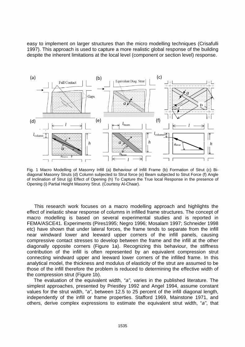
Fig. 1 Macro Modelling of Masonry Infill (a) Behaviour of Infill Frame (b) Formation of Strut (c) Bi-diagonal Masonry Struts (d) Column subjected to Strut force (e) Beam subjected to Strut Force (f) Angle of Inclination of Strut (g) Effect of Opening (h) To Capture the True local Response in the presence of Opening (i) Partial Height Masonry Strut. (Courtesy Al-Chaar).
This research work focuses on a macro modelling approach and highlights the effect of inelastic shear response of columns in infilled frame structures. The concept of macro modelling is based on several experimental studies and is reported in FEMA/ASCE41. Experiments (Pires1995; Negro 1996; Mosalam 1997; Schneider 1998 etc) have shown that under lateral forces, the frame tends to separate from the infill near windward lower and leeward upper corners of the infill panels, causing compressive contact stresses to develop between the frame and the infill at the other diagonally opposite corners (Figure 1a). Recognizing this behaviour, the stiffness contribution of the infill is often represented by an equivalent compression strut connecting windward upper and leeward lower corners of the infilled frame. In this analytical model, the thickness and modulus of elasticity of the strut are assumed to be those of the infill therefore the problem is reduced to determining the effective width of the compression strut (Figure 1b). The evaluation of the equivalent width, “a”, varies in the published literature. The simplest approaches, presented by Priestley 1992 and Angel 1994, assume constant values for the strut width, “a”, between 12.5 to 25 percent of the infill diagonal length, independently of the infill or frame properties. Stafford 1969, Mainstone 1971, and others, derive complex expressions to estimate the equivalent strut width, “a”, that
1535
consider parameters such as the length of contact between the column/beam and the infill, as well as the relative stiffness of the infill to the frame.
The expression used in this work was derived by Smith 1969 and Mainstone 1971, and have yielded consistently accurate predictions of the infilled frame in-plane behaviour when compared with experimental results (Smith 1969, Mainstone 1971, Klingner 1976, and Al-Chaar 1998). This expression for the strut width “a”, given in Eq. (1) and shown in Figure 1b, depends on the relative flexural stiffness of the infill and of the columns of the confining frame.
0.4
10.175a D H (1)
1/4
1
sin 2
4m
c col
E tH H
E I h
(2)
1 2red i i
a a R R (3)
where (R1)i is the reduction factor for in-plane evaluation due to the presence of openings, and (R2)i is the reduction factor for in-plane evaluation due to existing infill damage. As far as the global level response is concerned, the compression struts representing infill stiffness of solid infill panels may be placed concentrically across the diagonals of the frame, effectively forming a concentrically braced frame system (Figure 1c). In this arrangement, the forces imposed on columns and beams of the frame by the infill are not represented. To account for these local effects, compression struts may be placed eccentrically within the frames, as shown in Figure 1d and Figure 1e. If the analytical models incorporate eccentrically located compression struts, the result should yield infill effects on columns directly. The equivalent masonry strut is to be connected to the frame members as depicted in Figure 1f. The infill forces are assumed to be mainly resisted by the columns, and the struts are placed accordingly. The strut is pin-connected to the column at a distance lcolumn from the face of the beam. This distance is defined in Eq. (4) and Eq. (5) and is calculated using the strut width, “a”, without any reduction factors.
coscolumn
column
al
(4)
cos
tan columncolumn
ah
l
(5)
Several experimental studies and observations following earthquake events, showed that the failure of the surrounding columns takes place before the failure of the infill panel. This is usually observed at the top of the columns. In the case of weak
1536

frames, shear failure of columns is responsible for the development of fragile mechanism. In this type of mechanism, the resultant infilled frame structure’s ultimate capacity is significantly smaller than the sum of the single strengths of the infill and frame. Celarec 2013 observed that the strength of the structures and their deformation capacity are considerably overestimated if the column shear failure due to the effects of masonry infills is ignored, whereas the mean annual frequency of limit-state exceedance for the analyzed limit states is significantly higher than that estimated for the case if the shear failure of columns is neglected. Relatively few researchers have attempted to explicitly include inelastic shear response in assessment of R/C structures (Takayanagi et al. 1979; Thom 1983; D’Ambrisi and Filippou 1997; Ricles et al. 1998; Petrangeli et al. 1999; Pincheira et al. 1999; Lee and Elnashai 2001; Elwood and Moehle 2003; Cosenza et al. 2006; Marini and Spacone 2006). The limited number of such studies, compared to those dealing with predominantly flexural response, should be attributed to the fact that the determination of the shear strength of R/C members, and particularly of the shear deformation characteristics, are still controversial or unresolved issues. The price to be paid for the model simplicity (macro modelling technique) can be found in its limitation to simulate directly the internal forces acting on the columns, because the contact between the infill and the frame is neglected in the single-strut model. Thus, several attempts have been made to extend the applications of simple macro-models to improve their ability to simulate phenomena such as the interaction between infill panels and weak/strong frame response. This study is also an attempt to enhance the capability of macro models so to capture the true strength and deformation capacity of infilled frames structures. In order to achieve the objective, inelastic shear response of column proposed by Marine and Spacone 2006 is aggregated with nonlinear beam column element in OpenSees frame work. Seismic building codes such as Eurocode 8 (EC8) [DD ENV 1998-1 1996] contain provisions for the design of infilled RC frames. EC8 (section 2.9) specifies that the period of the structure used to evaluate the seismic base shear shall be the average of that for the bare frame and the elastic infilled frame. The demand on the frame members is then determined by modelling the frame without the infill struts. Recently, a number of works have addressed the issue of the behaviour, design, and analysis of infilled frames. Those making reference to EC8 generally conclude that Eurocode 8 is overly conservative by not modelling the infill panels when evaluating member demand. Fardis (2000) concludes that for infills with regular distribution, the overall effect of infills is found to be beneficial and designing the structure as bare is conservative. The only adverse effect for regular structures is a tendency for drift concentration in the bottom storey; however, deformation demands in that storey are well below those required for a soft storey mechanism. For structures with an open bottom storey, the concentration of drift and structural damage of the bottom columns become significant. In structures with infilled panels along two adjacent sides, the response can be quasi-torsional. As a result, the far corner columns may need to be designed for the simultaneous peaks for the two directional components. In all other respects, the RC frame may be designed as bare. Several efforts have been made to improve the method of nonlinear static analysis.
1537

The more realistic alternative to static pushover is represented by dynamic time-history analysis. The development of probabilistic ground shaking hazard and characterization, and the availability of ground motion databases, help to carry out time history analyses spanning a range of hazard levels with a suite of input ground motion records. This method is referred to as Incremental Dynamic Analysis (IDA), (Vamvatsikos 2002). Being computer-intensive, IDA can benefit from parallel processing to accelerate application on realistic structural models. The IDA approach can give a clear indication of the relationship between the seismic capacity and the demand in terms of IDA plots. These IDA plots mainly represent the relationship between seismological intensity measures (IM), such as spectral acceleration at a reference structural period and engineering demand parameters (EDP), such as peak floor acceleration, interstory drift ratio etc. Furthermore, to review the results, IDA plots converted into 16, 50 and 84 percentiles summarized curves on such curves the desired limit-states can be defined by setting appropriate limits on the EDPs. Although some open issues still remain as far the scaling criterion of the ground motions is concerned (Faggella et al. 2013), IDA remain a valuable tool for probabilistic performance-based characterization of structural demand and for developing fragility curves. 2. METHODOLOGY
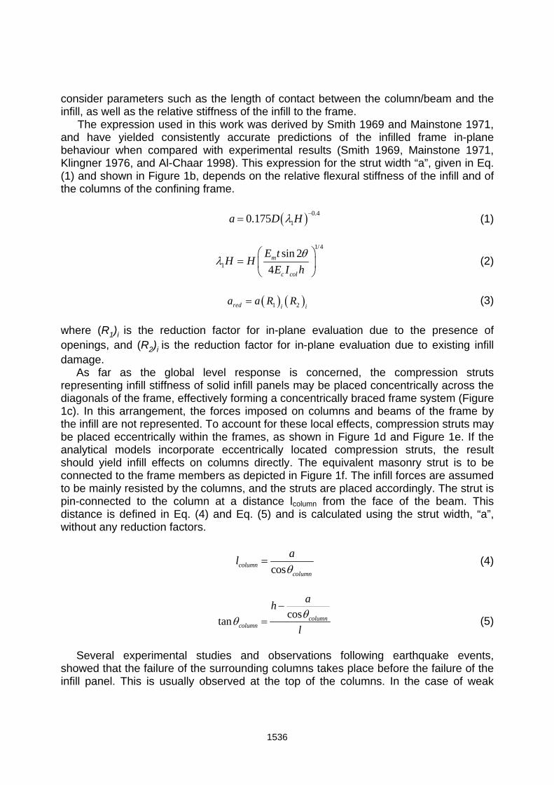
This paper deals with IDA analyses on 2D R/C infilled frame structures using the OpenSees framework. In this approach, IDA are carried out on three different configurations. The ground motion records have been selected using REXEL beta (Iervolino 2010). The 14 unscaled signals (Figure 2a) are extracted from European strong motion data by matching the NTC08 site specific target spectrum with a code specified period range. Ground motion records are then linearly scaled over a range of sixteen hazard levels from minor to severe hazard levels by using the probabilistic hazard curve made available by INGV (Figure 2b). The selected records are shown in the form of spectra in Figure 2c with the mean spectrum and the site specific target spectrum from NTC08 for the 10% in 50 years hazard level. To assess the variation in input hazard, the covariance in record spectral acceleration is shown in Figure 2d. This figure also highlights the magnitude of covariance associated with the case study frames corresponding to the period of the structure. A detailed nonlinear computational model of the frame structure has been developed, with the following assumptions:
1) Element types - All non-linear elements in the model are force-based fiber-section beam-column elements. The beam-column element has five integration points. Different model parameters are assigned to unconfined and confined concrete. Section shear is also modelled using the section aggregator procedure in OpenSees and providing a nonlinear shear constitutive law. Infill panels are modelled by truss elements.
2) Constitutive models - There are several material models available in OpenSees library. The Giuffrè-Menegotto-Pinto [CEB1996] stress–strain model is used for the steel reinforcement. The Kent 1982 stress–strain relationship is used for both
1538
confined and unconfined concrete fibers (with zero tensile strength). For infill panels, the back bone curve is determined according to ASCE41 provisions and assigned to bi-diagonal truss elements by using a uniaxial bilinear hysteretic material. To capture the local shear behaviour of frame members, linear and nonlinear shear laws are imposed on column elements.
3) Model masses - The mass of the structure is modelled using lumped masses at the nodes. Model masses are directly computed from the total dead load including the self-weight and the superimposed dead load. The live loads are accounted for with a 30% contribution in the model mass.
4) Viscous damping - The damping characteristics of the building are modelled using mass and stiffness proportional damping with 2% of the critical damping for the first two modes of vibration. The periods of these two modes estimated from the Eigen solution using the initial elastic stiffness matrix.
5) Solution strategy - Newmark– method is used as the time integrator with coeffcients =0.50, =0.25 and a time step of 0.01. For solving the nonlinear equilibrium equations the Newton–Raphson solution algorithm is used. Other algorithms may be used depending on the convergence of the solution.
0 10 20 30 40
-0.4
-0.2
0
0.2
0.4
Time(sec)
Acc
ele
ratio
n(g
)
14 Ground Motions Records
(a) 10
-210
-110
010
110-2
10-1
100
Annual Freq of Exceedence (%)
Peak
Gro
und A
ccele
ratio
n (
g)
(b)
(c)0 1 2 3
0
0.2
0.4
0.6
0.8
1
1.2
T(sec)
Pse
ud
o A
cce
lera
tion
(g)
(d)0 1 2 3
0
0.2
0.4
0.6
0.8
T(sec)
CO
V o
f Pse
udo
Acc
eler
atio
n(g)
Fig. 2 Characteristics of Suit of Ground Motions (a) 14-Natural Ground Motions (b) Site Specific Hazard Curve (c) Target Spectra and Mean Spectra of Natural Ground Motions (d) Covariance in Ground Motions Mean Spectra in terms of Period of Structures
1539
6) Selected EDPs and IM - Peak floor acceleration and interstory drift are used as
engineering demand parameters (EDP) in this study. For the IDA probabilistic characterization of the response the variation of the input intensity measure is expressed in terms of peak ground acceleration (PGA) consistent with the scaling of the ground motions.
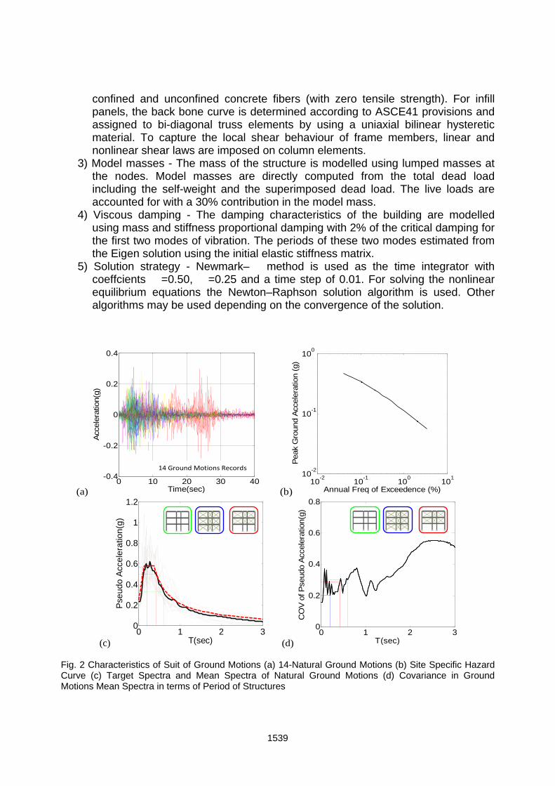
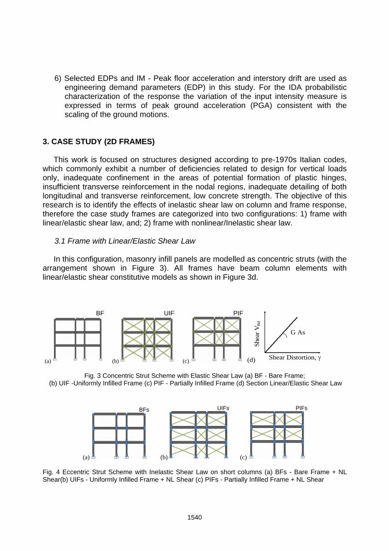
3. CASE STUDY (2D FRAMES) This work is focused on structures designed according to pre-1970s Italian codes, which commonly exhibit a number of deficiencies related to design for vertical loads only, inadequate confinement in the areas of potential formation of plastic hinges, insufficient transverse reinforcement in the nodal regions, inadequate detailing of both longitudinal and transverse reinforcement, low concrete strength. The objective of this research is to identify the effects of inelastic shear law on column and frame response, therefore the case study frames are categorized into two configurations: 1) frame with linear/elastic shear law, and; 2) frame with nonlinear/Inelastic shear law.
3.1 Frame with Linear/Elastic Shear Law In this configuration, masonry infill panels are modelled as concentric struts (with the arrangement shown in Figure 3). All frames have beam column elements with linear/elastic shear constitutive models as shown in Figure 3d.
(a) (b) (c)
BF UIF PIF
Shear Distortion,
She
ar V
Rd
G As
(d)
Fig. 3 Concentric Strut Scheme with Elastic Shear Law (a) BF - Bare Frame; (b) UIF -Uniformly Infilled Frame (c) PIF - Partially Infilled Frame (d) Section Linear/Elastic Shear Law
(a) (b) (c)
BFs UIFs PIFs
Fig. 4 Eccentric Strut Scheme with Inelastic Shear Law on short columns (a) BFs - Bare Frame + NL Shear(b) UIFs - Uniformly Infilled Frame + NL Shear (c) PIFs - Partially Infilled Frame + NL Shear
1540

3.2 Frame with Nonlinear/Inelastic Shear Law In this configuration (shown in Figure 4), masonry panels are modelled as eccentric struts in infilled frames. The short portions of columns created by the eccentric strut scheme are assigned nonlinear/inelastic shear law for all 3 types of frames configurations including the bare frame. All other beam column elements have elastic shear constitutive law.
Shear,V
Rd
ShearDistortion,
VRd, y Vu , u
Vu , u
(i)
(ii)
(a)
-2 -1 0 1 2
-200
-100
0
100
200
Sh
ea
r(K
N)
Shear Distorsion (%) (b)
Fig. 5 Section Shear Law (a) Different Shear Models ((i) Ductile & (ii) Brittle);
(b) Shear Hysteresis Response of Section
The inelastic shear constitutive model used in this case study is the one proposed by Marini and Spacone 2006 (shown in Figure 5) for constant axial load. In recent major earthquakes and in several experimental studies on infilled frames, the failure of the surrounding columns was observed prior to the infill panel failure. This is due to the shear forces induced by the interaction between frame columns and the infill panel. The larger shear force occurs along the contact length near the loaded corners where the sliding shear failure occurs, usually at the top of the columns. In order to capture this particular type of failure mechanism the eccentric strut scheme is used in this case study, which allows the strut force to be directly transferred to the column. The potential resulting shear failure can be captured using a nonlinear V-γ law, (shown in Figure 5a). The shear law has a peak point at VRd, γ y, which represents the section shear capacity. A linear descending branch follows the peak point whose initial and final points are VRd, γy and Vu, γu, respectively. The last point represents the residual shear capacity, for > γu V = Vu. By selecting the residual shear capacity either larger or smaller than the shear capacity VRd, ductile (i) or brittle (ii) shear failures can be modelled (Figure 5a). This way, the brittle failure of unreinforced or lightly reinforced concrete beams as well as the more ductile failure of fiber-reinforced concrete structures or jacket-strengthened members can be modelled. The hysteretic response of the column section shear law is shown in Figure 5b.
1541

0 0.5 1 1.5 20
0.1
0.2
0.3
0.4P
GA
(g)
Max IDRmax (%)
PE =5%
PE =10%
PE =63%
(a)
V
0 0.5 1 1.5 2
0
0.1
0.2
0.3
0.4
PG
A(g
)
Max IDRmax (%)
PE = 5%
PE = 10%
PE = 63%
(b)
V
0 0.2 0.4 0.6 0.80
0.1
0.2
0.3
0.4
PG
A(g
)
PFAmax(g)
V
PE = 63%
PE = 10%
PE = 5%
(c) 0 0.2 0.4 0.6 0.8
0
0.1
0.2
0.3
0.4
PG
A(g
)
PFAmax(g)
V
PE = 63%
PE = 10%
PE = 5%
(d)
0 200 400 6000
0.1
0.2
0.3
0.4
PG
A(g
)
Max Base Shear (KN)(e)
V
PE = 5%
PE = 63%
PE = 10%
0 200 400 600
0
0.1
0.2
0.3
0.4
PG
A(g
)
Max Base Shear (KN)
V
PE = 63%
PE = 10%
PE = 5%
(f) Fig. 6 Results of IDA (Green Curves for Bare Frame, Red Curves for Partially Infilled Frame and Blue Curves for Uniformly Infilled Frame) (a) EDP- Interstory Drift Ratio without Inelastic Shear (b) EDP- Interstory Drift Ratio with Inelastic Shear (c) EDP- Peak Floor Acceleration without inelastic shear (d) EDP- Peak Floor Acceleration with inelastic shear (e) EDP- Maximum Base Shear without inelastic shear (f) EDP- Maximum Base Shear with inelastic shear
1542

4. NUMERICAL RESULTS
Presented here are some preliminary results from the IDA analyses to compare the response obtained with the different configurations of infilled frames and to evaluate the impact of the shear strength and nonlinear shear rule in the eccentric infill strut arrangements.
Results are presented in the form of IDA curves of different EDPs at increasing hazard level assuming the PGA as IM. IDA curves are presented in terms of mean value of the max EDP and mean +/- the standard deviation. By comparing Figures 6a and 6b it is observed that in the configurations of bare frame and partially infilled frame accounting for the nonlinear shear law in columns does not influence the EDP maximum interstory drift ratio (max IDRmax). The shear strength and hysteretic rule become influent for the uniformly infilled configuration only after the PGA=0.15g hazard level, where a considerable increase in IDRmax is observed. This is due to the failure in the short columns and results in some stress release in the corresponding infill struts/panels, according to the nonlinear rule chosen for shear behaviour. Figures 6c and 6d show that EDP peak floor acceleration (PFAmax) is not considerably affected in the configurations of bare and partially infilled frames. On the other hand, in the case of uniformly infilled frame the PFAmax decreases for IM greater than PGA=0.15g, due to the rapid stiffness degradation following failure of the short columns). Similar observation can be made for the case of EDP maximum base shear as shown in Figures 6e and 6f.
0 0.2 0.4 0.6 0.8 1
0
100
200
300
400
500
600
Max Roof Disp/Build Height (%)
Max
Bas
e S
hear
(K
N)
PE 63%PE 10%PE 5%
(a)
V
0 0.2 0.4 0.6 0.8 1
0
100
200
300
400
500
600
MaxRoof Disp/Build Height (%)
Max
Bas
e S
hear
(K
N)
PE 63%
PE 10%
PE 5%
(b)
V
Fig. 7 Results of IDA (a) IDA Capacity Curves without Inelastic Shear;
(b) IDA Capacity Curves with Inelastic Shear
The plots in Figure 7 are obtained combining the mean IDA curves shown in Figure 6 in terms of max Base Shear vs. max total drift (i.e. the max roof displacement divided by the total building height). The curve so obtained give a measure of the dynamic
1543
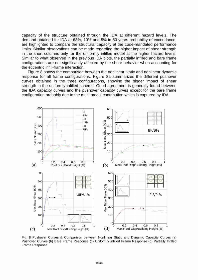
capacity of the structure obtained through the IDA at different hazard levels. The demand obtained for IDA at 63%, 10% and 5% in 50 years probability of exceedance, are highlighted to compare the structural capacity at the code-mandated performance limits. Similar observations can be made regarding the higher impact of shear strength in the short columns only for the uniformly infilled model at the higher hazard levels. Similar to what observed in the previous IDA plots, the partially infilled and bare frame configurations are not significantly affected by the shear behavior when accounting for the eccentric infill-frame interaction.
Figure 8 shows the comparison between the nonlinear static and nonlinear dynamic response for all frame configurations. Figure 8a summarizes the different pushover curves obtained in the three configurations, showing the bigger impact of shear strength in the uniformly infilled scheme. Good agreement is generally found between the IDA capacity curves and the pushover capacity curves except for the bare frame configuration probably due to the multi-modal contribution which is captured by IDA.
0 0.2 0.4 0.6 0.8 10
100
200
300
400
500
600
Roof Disp/Build Height (%)
Bas
e S
hear
(K
N)
BFBFsUIFUIFsPIFPIFs
(a) 0 0.2 0.4 0.6 0.8 1
0
100
200
300
400
500
600
Max Roof Disp/Building Height (%)
Max
Bas
e S
hear
(K
N)
BF/BFs
(b)
V
V
0 0.2 0.4 0.6 0.8 10
100
200
300
400
500
600
Max Roof Disp/Building Height (%)
Max
Base
Shea
r (K
N)
UIF/UIFs
(c)
V
V
0 0.2 0.4 0.6 0.8 1
0
100
200
300
400
500
600
Max
Bas
e S
hear
(K
N)
Max Roof Disp/Building Height (%)
PIF/PIFs
(d)
V
V
Fig. 8 Pushover Curves & Comparison between Nonlinear Static and Dynamic Capacity Curves (a) Pushover Curves (b) Bare Frame Response (c) Uniformly Infilled Frame Response (d) Partially Infilled Frame Response
1544

Figure 9 shows the impact of the NL shear behavior in the different models by taking the ratio of the max EDPs measured with the NL shear behavior to the value of the EDP obtained with elastic shear rule. It is evident how the response of the bare frame model and of the partially infilled model is not affected by the shear behavior, neither in terms of drift, acceleration nor base shear. Instead, in the case of uniformly infilled frame there is a significant influence of the shear behavior on the overall drift response. The shear behavior is activated from hazard levels higher than the 63%PoE in 50 years, and results in drift amplifications in the order of 2 to 2.3 for PGA intensities in the range of 10% to 5%PoE in 50 years. Figures 10 and 11 compare the covariations in input and in system response and the impact of the nonlinear shear model on the dispersion of EDPs. At low PGA intensities the structures respond in the linear range, therefore the COVs of the EDPs are comparable to those of the input hazard at the different fundamental periods. As the systems develop nonlinear behavior the COV of EDPS is expected to more markedly depart from the COV of the input due to the structural period shift.
0 0.5 1 1.5 2 2.50
0.1
0.2
0.3
0.4
Ratios of Max IDRmax
PG
A(g
)
BFs/BFUIFs/UIFPIFs/PIF
0 0.5 1 1.5 2 2.5
0
0.1
0.2
0.3
0.4
PG
A(g
)
Ratios of PFAmax(g) 0 0.5 1 1.5 2 2.5
0
0.1
0.2
0.3
0.4
PG
A(g
)
Ratios of Max Base Shear
PE = 5%
PE = 10%
PE = 63%
V
V
(a) (b) (c)
Fig. 9 Effects of Inelastic Shear on EDPs (a) Effects on Interstory Drift Ratio (b) Effects on Peak Floor Acceleration (c) Effects on Base Shear
0 1 2 30
0.2
0.4
0.6
0.8
T(sec)
CO
V o
f Pse
udo
Acc
eler
atio
n(g)
0 0.1 0.2 0.3 0.4
0
0.2
0.4
0.6
0.8
PGA(g)
CO
V o
f M
ax
IDR
ma
x (%
)
0 0.1 0.2 0.3 0.4
0
0.2
0.4
0.6
0.8
PGA(g)
CO
V o
f P
FA
ma
x(g)
(a) (b) (c)
BF UIF PIF
V
V
Fig. 10 Propagation of dispersion in input hazard to IDA Structural Response with elastic shear law. (a) COV of ground motions spectral ordinates over a range of periods, (b) COV trend of Max IDRmax (c) COV trend of PFAmax.
1545

In Figure 10b for the models with elastic shear, the COV of IDR shows a generally increasing trend as the input intensity increases. The PIF shows a clearly increasing trend only for PGA greater than 0.12 g. The IDR of the BF model does not show a clear trend. The COV of EDP PFAmax decreases with the hazard level in all models, as shown in Figure 10c. In the case of configurations with nonlinear shear behavior and eccentric struts, shown in Figure 11, for the uniformly infilled frame the increasing trend of COV of IDRmax is interrupted by a sharp peak for PGA in the range 0.15g to 0.28g. This behavior can be ascribed to the shear failure of the short columns. Accounting for the nonlinear shear behavior does not affect the trend of the COV of PFAmax for all models considered.
0 1 2 30
0.2
0.4
0.6
0.8
T(sec)
CO
V o
f Pse
udo
Acc
eler
atio
n(g)
0 0.1 0.2 0.3 0.4
0
0.2
0.4
0.6
0.8
PGA(g)
CO
V o
f M
ax
IDR
ma
x (%
)
0 0.1 0.2 0.3 0.4
0
0.2
0.4
0.6
0.8
PGA(g)
CO
V o
f P
FA
max(
g)
V
V
PIFs UIFs BFs
(a) (b) (c)
Fig. 11 Propagation of dispersion in input hazard to IDA Structural Response with nonlinear shear law. (a) COV of ground motions spectral ordinates over a range of periods, (b) COV trend of Max IDRmax (c) COV trend of PFAmax. 5. CONCLUSIONS
This paper presented a study of the nonlinear seismic behaviour of a non-ductile structure in presence of strong infill-frame interaction using performance-based methods and a probabilistic framework for the analysis of the response. Results from conventional design configurations that are typically used in design practice, such as the bare frame configuration, and the indefinite shear strength assumption, are compared with more realistic models of components and mechanisms. A nonlinear shear behaviour is incorporated in the columns sections which accounts for the EC8 provisions for the shear strength and softening behaviour, thus representing the realistic interaction of the frame with eccentric infill struts. ASCE41 provisions are used to model the nonlinear infill behaviour of the equivalent struts. The results are processed through IDA curves which allow to trace the response over a range of input intensities and to identify the main mechanisms that dominate the response. This is done through a number of configurations across the uniformly infilled model, by the partially infilled model and by the bare frame model.
1546

We find that in the configurations of bare frame and partially infilled frame accounting for the nonlinear shear law in columns does not influence the maximum interstory drift ratio. The shear strength and hysteretic rule become influent for the uniformly infilled configuration approaching the life safety limit state, where a considerable increase in drift is observed. Other structural response parameters such as floor accelerations are generally not affected by the shear strength in frame-infills interaction. It was also observed that the strength of the uniformly infilled frames and their deformation capacity are significantly overestimated if the column shear failure due to the effects of masonry infills (strong infill) is neglected, whereas the mean annual frequency of limit-state exceedance for the analyzed limit states is significantly larger than that estimated for the case if the shear failure of columns is neglected. The prevalence of the shear mechanism is also detected by processing the statistics of the response and by comparing the covariance of the output with that of the input ground motions. The preliminary results and the probabilistic performance-based approach are being used to develop a simplified method of assessment of the vulnerability of frames prone to shear failure due to infill-frame interaction. Further analyses will incorporate also the fragile shear behaviour of beam-column connections. Extension of the study in presence of local strengthening will provide information also on the performance achievable with sustainable retrofit solutions such as wrapping with fiber reinforced polymers or other low-impact technique. REFERENCES Al-Chaar, G. and D. Abrams. (2001), “Parametric Studies on Seismic Behavior of
Frame-Infill Systems.” Proceedings of the Ninth Canadian Masonry Symposium, New Brunswick, Canada.
American Society of Civil Engineers/Structural Engineering Institute, (2006), “Seismic Rehabilitation of Existing Buildings, ASCE/SEI 41-06.” American Society of CivilEngineers, Washington DC
Angel R., Abrams D., Shapiro D., Uzarski J. and Webster M. (1994), “Behavior of Reinforced Concrete Frames with Masonry Infills.” Civil Engg. Studies, Structural Research Series No. 589,UILU-ENG-94-2005, Dept. of Civil Engineering, University of Illinois at Urbana Champaign.
Braga, F., Gigliotti, R., Laterza, M., D’Amato, M. and Kunnath, S.(2012), “A modified steel bar model incorporating bond-slip for seismic assessment of concrete structures.” ASCE, Journal of Structural Engineering. 138,1342-1350.
Calarec, D. and Dolsek, M. (2013), “Practice-oriented probabilistic seismic performance assessment of infilled frames with consideration of shear failure of columns.” Earthquake Engng Struct. Dyn; 42:1339–1360
CEN. Eurocode 8: Design of structures for earthquake resistance — Part 1: General rules, seismic actions and rules for buildings. Final draft. prEN 1998-1. Brussels; 2003.
Combescure, D. and Pegon, P.(2000), “Application of the local-to-global approach to
1547

the study of infilled frame structures under seismic loading.” Nuclear Engineering and Design ; 196(1):17–40.
Cosenza, E., Manfredi, G. and Verderame, G.M.(2006), “A fibre model for push-over analysis of underdesigned reinforced concrete frames.” Computers and Structures; 84:904–916
Crisafulli, F.J. (1997), Seismic Behaviour of Reinforced Concrete Structures with Masonry Infills, PhD Thesis, Department of Civil Engineering, University of Canterbury, New Zealand.
D’Amato, M., Braga. F., Gigliotti, R., Kunnath, S. and Laterza, M. (2012), “Validation of A Modified Steel Bar Model Incorporating Bond‐Slip for Seismic Assessment of Concrete Structures.” Journal of Structural Engineering, 1351-1360.
D’Ayala, D., Worth, J. and Riddle O.(2009), “Realistic shear capacity assessment of infill frames: comparison of two numerical procedures.” Engineering Structures; 31(8):1745–1761.
Dymiotis, C., Kappos A.J. and Chryssanthopoulos, M.K. (2001), “Seismic reliability of masonry-infilled RC frames,” Journal of Earthquake Engineering, 127(3), 296–305.
Faggella, M. (2008), “Nonlinear Modelling, Seismic Response Analysis and Probabilistic Demand Sensitivity of a Three-Dimensional R/C Building.” Ph.D. Dissertation, University “G.D’Annuzio” Chieti-Pescara.
Faggella, M., Barbosa, A.R., Conte, J.P., Spacone, E. and Restrepo, J.I. (2008), “Seismic Assessment of R/C Building Structure Through Nonlinear Probabilistic Analysis with High-Performance Computing.” In MERCEA08 Seismic Engineering International Conference, Reggio Calabria, Italy.
Faggella, M., Barbosa, A.R., Conte, J.P., Spacone, E. and Restrepo, J.I. (2013), “Probabilistic seismic response analysis of a 3-D reinforced concrete building.” Structural Safety,44, 11-27.
Fajfar, P. and Fischinger, M. (1988), “N2—a method for nonlinear seismic analysis of regular structures.” Proceedings of the 9th World Conference on Earthquake Engineering, Vol. 5, 111–116, Tokyo–Kyoto, Japan.
Fardis M.N. (2000), “Design provisions for masonry infilled RC frames.” Proceedings 12th World Conference on Earthquake Engineering, Auckland, New Zealand.
FEMA 273 (1997), NEHRP Commentary on the Guidelines for the Seismic Rehabilitation of Buildings, FEMA, Oct.
FEMA 356 (2000), Prestandard and Commentary for the Seismic Rehabilitation of Buildings, prepared by the American Society of Civil Engineers, Reston, VI.
Filippou, F.C. (1986), “A Simple Model for Reinforcing Bar Anchorages Under Cyclic Excitations.” Journal of Structural Engineering, ASCE, 112(ST7),1639-1659.
Gigliotti, R. (2002), “Strutture in c.a. progettate per soli carichi verticali:sperimentazioni su nodi trave-pilastro.” Ph.D. thesis, Univ. of Salerno,Salerno, Italy.
Iervolino, I., Galasso, C. and Cosenza, E. (2010), “REXEL: Computer Aided Record Selection for Code-based Seismic Structural Analysis.” Bull Earthquake Eng (2010)8, 339-362.
Klinger, R.E. and Bertero, V.V. (1976), “Infilled frames in earthquake resistant construction.” Earthquake Engineering Research Center, University of California, Berkeley, CA, Rep. EERC 76-32, Dec
Krawinkler, H. and Seneviratna, G.D.P.K. (1998), “Pros and cons of a pushover
1548

analysis of seismic performance evaluation.” Engineering Structures1; 20,452–464. Mainstone, R. (1971), “On the stiffnesses and strengths of infilled frames”, Proceedings
of the Institute of Civil Engineers Supplement IV, 57–90. Marini, A. and Spacone, E. (2006), “Analysis of Reinforced Concrete Elements
Including Shear Effects.” ACI Structural Journal, Vol. 103(5), 645-655. Mehrabi, A.B., Shing, P.B., Schuller, M. and Noland, J. (1996), “Experimental
evaluation of masonry-infilled RC frames", J. Strut. Eng., 122(3), 228-237. Mosalam, K., White, R.N. and Gergely, P. (1997), “Seismic Evaluation of Frames with
Infill Walls Using Quasi-static Experiments”. NCEER-97-0019. Paulay, T. and Priestley, M.J.N. (1992), Seismic Design of Reinforced Concrete and
Masonry Buildings, John Wiley & Sons, New York. Petrangeli, M., Pinto, P.E. and Ciampi, V. (1999), “Fiber element for cyclic bending and
shear of RC structures I : Theory.”. J Eng Mech ;125:9. Smith, B.S. (1962), “Lateral Stiffness of Infilled Frames.” Journal of Structural Division,
ASCE. Vol. 88(6), 183-199. Smith, B.S. and Carter, C. (1969), “A method of analysis for infilled frames”, Proc.,
Instn. Civ. Engrs., 44, 31-48. Smyrou, E., Blandon, C., Antoniou, S., Pinho, R. and Crisafulli, F. (2011),
“Implementation and verification of a masonry panel model for nonlinear dynamic analysis of infilled RC frames,” Bulletin of Earthquake Engineering ; 9(5):1519–1534.
Stavridis, A. (2009), “Analytical and Experimental Study of Seismic Performance of Reinforced Concrete Frames Infilled with Masonry Walls,” Ph.D. Dissertation, University of California, San Diego.
Vamvatsikos, D. and Cornell, C.A. (2002), “Incremental dynamic analysis.” Earthquake Engineering & Structural Dynamics, Vol.3, 491-514.
1549