asm servomotoren/servomotors series asm - lti motion · katalog asm-servomotoren 1 - 1 1 synchron-...
TRANSCRIPT

ServomotorenBestellkatalog
Baureihe ASMAsynchronservomotor
Nennmoment von23 bis 70 Nm
ServomotorsOrder Catalogue
Series ASMasynchronous servomotors
Rated torque from23 to 70 Nm

Ord
er C
atal
ogue
AS
M S
ervo
mot
ors
0 - 2 Bes
tellk
atal
og
AS
M-S
ervo
mo
tore
n
Kapitel 1: deutsche Version
Chapter 1: German version
Kapitel 2: englische Version
Chapter 2: English version
Bestellkatalog ASM-Servomotoren
Order Catalogue ASM Servomotors
Id.-Nr.: 0814.04 B.1-00Stand: Oktober 2004
ID No.: 0814.04 B.1-00Date October 2004
Technische Änderungen vorbehalten.
We reserve the right to make technical changes.

Kat
alog
AS
M-S
ervo
mot
oren
1 - 1
1
Synchron- oder Asynchronmotor?
Die richtige Motorauswahl
Konstruktiv unterscheiden sich die Servomoto-ren in erster Linie durch das Aufbauprinzip desLäufers:
• Kurzschlußkäfig-Läufer bei Asynchronservomoto-ren (ASM)
• Dauermagnet-Läufer bei Synchronservomotoren (LSH)
Ob nun der Synchron- oder doch der Asyn-chronmotor besser geeignet ist, entscheidetIhre Anwendung.
Erlaubt Ihre Anwendung ein etwas größeresBauvolumen, ist im allgemeinen der Asyn-chronmotor die wirtschaftlichste Lösung;zusätzlich besticht der ASM-Motor durch sehrhohe Maximaldrehzahlen bei konstanter Maxi-malleistungsabgabe.
Ist jedoch eine extrem kleine Baugröße beihoher Leistungsdichte gefragt, oder ist fürhohe dynamische Ansprüche ein niedrigesRotor-Trägheits-Moment gefordert, dann istder permanentmagneterregte Synchonservo-motor der Baureihe LSH der richtige für IhreAnwendung.
Eigenschaften der Servomotoren
Die Synchron- und Asynchronservomotorensind optimal auf die c-line Servoregler abge-stimmt. Sie besitzen eine hohe Leistungs-dichte und sind auf lange Lebensdauer ausge-legt. Geringe Rastmomente sorgen fürexzellente Rundlaufeigenschaften.
Synchron-Servomotoren Baureihe LSH:
• hochenergetische Neodym-Eisen-Bor-Magnete
• geringe Rotorträgheitsmomente
• hohe Leistungsdichte
• exzellente Dynamik
• integrierter PTC
• Resolver
• Schwingstärkestufe R nach DIN ISO 2373 (optio-nal Schwingstärkestufe S möglich)
Nähere Informationen finden sie im BestellkatalogLSH-Motoren.
Asynchronservomotoren Baureihe ASM:
• robuster Käfigläufer
• Feldschwächbereich bis 8000 1/min. mit konstan-ter Leistung
• Welle mit Paßfeder
• integrierter PTC
• Klemmkasten
• Schwingstärkestufe N nach DIN ISO 2373 (optio-nal Schwingstärkestufe R möglich)
• sehr gutes Preis-/ Leistungsverhältnis

Kat
alog
AS
M-S
ervo
mot
oren
1 - 2
1
Grundausstattung der ASM-Servomotoren Merkmal ASM
Maschinenart Asynchronservomotor Baureihe ASM
Bauform (DIN 42948) IM B35, IM B5, V1, V3
Schutzart (DIN 40050) IP65, Wellendichtung IP64 (Option IP65)
Isolierstoff-KlasseIsolierstoff-Klasse F nach VDE0530 Wicklungsübertemperatur ∆t = 100°C,
Umgebungstemperatur tu = +40 °C
Kühlung Selbstkühlung (IC 0041) IP65
Anstrich RAL 9005 (matt schwarz)
Wellenende auf A (D) Seite Paßfeder und Paßfedernut DIN 6885, Toleranzfeld k6
Flanschabmessung DIN 42948 und IEC 72
Rundlaufgenauigkeit, Koaxialität und Planlauf nach DIN 42955
Toleranz N (normal), R (reduziert) auf Anfrage
Schwingstärke nach ISO 2373 Stufe R, als Option S
Thermische Motorüberwachung Kaltleiter PTC in der Ständerwicklung
Drehmomentbelastung
Um eine thermische Überlastung des Motors auszuschließen, darf das effektive Belastungsmoment bei mittlerer Drehzahl nicht oberhalb der S1-Kennlinie liegen.
Maximales ImpulsdrehmomentTypisch 2- bis 5faches Nennmoment, je nach Reglerzuordnung.
Das 3- bis 5fache Nennmoment ist max. für 0,2 s zulässig.
Anschlußart von Motor, Kaltleiter und Hal-tebremse
Anschluß über Klemmkasten
Anschlußart des Gebersystems Signalstecker (Gegenstecker nicht im Lieferumfang)
M 0
NM
M
S1
nN n
Meff
Σ M2
n tn×( )tges
-----------------------------= nΣ nn tn⋅( )
tges----------------------=

Kat
alog
AS
M-S
ervo
mot
oren
1 - 3
1
Bestellschlüssel Asynchronservomotoren ASM
Bestellschlüssel Asynchronservomotoren ASM
AS M 3 4 - 2 0 R2 1 - 0
Asynchronservomotor
Motortyp
Bauform Flansch, SelbstkühlungBauform Flansch, FremdkühlungBauform Flansch und Fuß, SelbstkühlungBauform Flansch und Fuß, Fremdkühlung
MFHV
Bauform / Kühlart
Flansch 110 x 110 mmFlansch 140 x 140 mmFlansch 190 x 190 mmFlansch 260 x 260 mm
1234
Baugröße Flansch
Baulänge 1Baulänge 2Baulänge 3Baulänge 4Baulänge 5
1234 5
Baulänge
3 x 190 V3 x 330 V3 x 480 V
124
Anschlußspannung
mit Haltebremse permanent erregtohne Haltebremse
10
Haltebremse
Resolver 4-poligECN 1313ohne Geber
R2G500
Drehgebersystem
1500 1/min2000 1/min3000 1/min
123
Bemessungsdrehzahl
Leistungsanschluß Klemmkasten, Drehgeber gerade steckbar 0
Anschlußtechnik
rot = Vorzugstyp
Motor-Baugrößen ASM33 ASM34 ASM41 ASM42 ASM43
Stilstands-moment
27,5 Nm 42 Nm 47 Nm 70 Nm 85 Nm
Nennmoment 23 Nm 35 Nm 40 Nm 60 Nm 70 Nm
Netzspannung 3 x 400 V
Einbaufenster 190 mm 260 mm
Kat
alog
AS
M-S
ervo
mot
oren
1 - 4
1
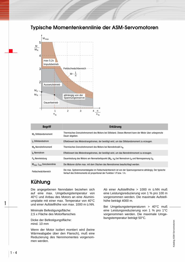
Typische Momentenkennlinie der ASM-Servomotoren
Kühlung Die angegebenen Nenndaten beziehen sichauf eine max. Umgebungstemperatur von40°C und Anbau des Motors an eine Alumini-umplatte mit einer max. Temperatur von 40°Cund einer Aufstellhöhe von max. 1000 m ü.NN.
Minimale Befestigungsfläche:2,5 x Fläche des Motorflansches
Dicke der Befestigungsfläche:mind. 10 mm
Wenn der Motor isoliert montiert wird (keineWärmeabgabe über den Flansch), muß eineReduzierung des Nennmomentes vorgenom-men werden.
Ab einer Aufstellhöhe > 1000 m ü.NN mußeine Leistungsreduzierung von 1 % pro 100 mvorgenommen werden. Die maximale Aufstell-höhe beträgt 4000 m.
Bei Umgebungstemperaturen > 40°C mußeine Leistungsreduzierung von 1 % pro 1°Cvorgenommen werden. Die maximale Umge-bungstemperatur beträgt 50°C.
Begriff Erklärung
M0 Stillstandsmoment Thermisches Grenzdrehmoment des Motors bei Stillstand. Dieses Moment kann der Motor über unbegrenzte Dauer abgeben.
I0 Stillstandsstrom Effektivwert des Motorstrangstromes, der benötigt wird, um das Stillstandsmoment zu erzeugen.
MN Nenndrehmoment Thermisches Grenzdrehmoment des Motors bei Nenndrehzahl nN.
IN Nennstrom Effektivwert des Motorstrangstromes, der benötigt wird, um das Nenndrehmoment zu erzeugen.
PN Nennleistung Dauerleistung des Motors am Nennarbeitspunkt (MN, nN) bei Nennstrom IN und Nennspannung UN.
Mmax, Imax Grenzkennlinie Die Motoren dürfen max. mit dem 5fachen des Nennstromes beaufschlagt werden.
FeldschwächbereichDie max. Spitzenmomentabgabe im Feldschwächbereich ist von der Spannungsreserve abhängig. Der typische Verlauf des Drehmoments ist proportional der Funktion 1/f bzw. 1/n.
5
4
3
2
1 2 3n
M0
NM
NMM
maxM
4
N
nnN
abhängig von derSpannungsreserve
Aussetzbetrieb
M~ n1
Feldschwächbereich
max 0,2sImpulsbetrieb
Dauerbetrieb

Kat
alog
AS
M-S
ervo
mot
oren
1 - 5
1
Auswahlliste Vorzugstyp Servomotor - Servoregler
Technische Daten ASM-Servomotoren für 400 V
Weitere Motortypen auf Anfrage.
Einbaufenster[mm]
MotortypStillstands-
momentM0 [Nm]
Nenn-momentMN [Nm]
Nenn-drehzahl nN
[1/min]
Servoregler1)
Nenn-strom Ü2)
190 x 190 ASM33-20R21-0 27,5 23,0 1500CDD/CDE34.010
10 2,1
190 x 190 ASM34-20R21-0 42,0 35,0 1500CDD/CDE34.014
14 2,0
260 x 260 ASM41-20R21-0 47,0 40,0 1500CDD/CDE34.024
24 2,4
260 x 260 ASM42-20R21-0 70,0 60,0 1500CDD/CDE34.032
32 2,3
260 x 260 ASM43-20R21-0 85,0 70,0 1500CDD/CDE34.032
32 1,9
1) zugeordneter Servoregler bei Auslegung 1:1 (Nennstrom Motor ≤ Nennstrom Servoregler) 2) Ü = Überlastfähigkeit des Systems
BezeichnungM0
[Nm]MN
[Nm]PN
[kW]I0
[A]IN
[A]
nN
[min-1]
nmax
[min-1]
JL [kgcm²]
l [mm]m
[kg]
ASM33-20R21-0 27,5 23 3,6 10,3 8,7 1500 8000 130 387 41,5
ASM34-20R21-0 42,0 35 5,5 15,1 12,6 1500 8000 209 482 56,6
ASM41-20R21-0 47,0 40 6,3 21,0* 17,9* 1500 8000 450 408 87
ASM42-20R21-0 70,0 60 9,4 30,0 25,5 1500 8000 740 498 113
ASM43-20R21-0 85,0 70 11,0 37,0 30,4 1500 8000 960 568 135
* UN = 310 V
Still
stan
dsm
omen
t
Nenn
mom
ent
Nenn
leis
tung
Still
stan
dsst
rom
Nenn
stro
m
Nenn
dreh
zahl
max
. zul
. Dre
hzah
l
Träg
heits
mom
ent d
e sLä
ufer
s
Gesa
mtlä
nge
Mas
se

Kat
alog
AS
M-S
ervo
mot
oren
1 - 6
1
Anschlußtechnik
Abbildung Leistungsanschluß Geberanschluß
Leistungsanschluß über KlemmkastenKontaktstifte für 12pol. Anschluß-
dose: ∅ 1 mm
Ringösengröße:
ASM = M6
PTC/Bremse = M3
1/2 - Thermistorschutz PTC
BR - Haltebremse (Option)
U,V,W - Motoranschluß
- Erde
1 - SIN- (S4)
2 - COS+ (S1)
5 - REF+ (R1)
7 - REF- (R2)
10 - SIN+ (S2)
11 - COS- (S3)
9 - nicht belegt
12 - nicht belegt
3,4,6,8 - nicht belegt
+ –
1
2
U V W
BR BR2
U V W
1
2
34
56
7
89
10 P
11
12
Resolver

Kat
alog
AS
M-S
ervo
mot
oren
1 - 7
1
Konfektionierte Geberleitungen
Technische Daten:
Geberleitung KRY-KS-005 Bestellschlüssel
K RY - KS 005
Geberleitung
Konfektionierte Leitung
ResolverleitungGeberleitung SSI (G3, G5)
RYGS
Gebersystem
Kettenschleppfähig KS
Ausführung
Länge 2 mLänge 3 mLänge 5 mLänge 8 mLänge 10 mLänge 15 mLänge 20 m
002003005008010015020
Leitungslänge
KRY-KSxxx KGS-KSxxx
Reglertyp CDD/CDE3000
Motoren mit Gebersystem ResolverG5 (Singleturn-Geber mit SSI-Schnitt-
stelle)
Kettenschleppfähig ja
Mindestbiegeradius:bei fester Verlegung
bei flexiblem Einsatz
-
90 mm
40 mm
100 mm
Temperatur-bereich: bei fester Verlegung
bei flexiblem Einsatz -40 ... +85 °C
-35 ... +80 °C
-35 ... +80 °C
Kabeldurchmesser ca. 8,8 mm 8,0 mm
Material des Außenmantels PUR PUR
Beständigkeitöl-, hydrolyse- u. mikrobenbeständig
(VDE0472) öl-, hydrolyse- u. mikrobenbeständig
(VDE0472)
Zulassungen
UL-Style 20233,80 °C - 300 V,
CSA-C22.2N.210-M90, 75 °C - 300 V FT1
-

Kat
alog
AS
M-S
ervo
mot
oren
1 - 8
1

Ord
er C
atal
ogue
AS
M S
ervo
mot
ors
2 - 1
1
Synchronous or asynchronous motor?
Selecting the right motor
The servomotors differ primarily in terms ofrotor design:
• Squirrel-cage rotors in asynchronous servomotors (ASM)
• Permanent magnet rotors in synchronous servo-motors (LSH)
The question of whether synchronous or asyn-chronous is more suitable will be determinedby your application.
If your application allows a little more space,the asynchronous motor is generally the mostcost-effective solution. Another key feature ofthe ASM motor is its very high maximumspeeds at constant maximum output.
If you need very compact design combinedwith high power density, or a low rotor momentof inertia for high dynamic demands, the per-manent-field synchronous servomotor LSH isthe right choice for your application.
Servomotor features
The synchronous and asynchronous servomo-tors are optimally attuned to the c-line servo-controller. They offer high power density andare designed for long life. Low cogging torquesensure outstanding smoothness of running.
LSH series synchronous servomotors:
• High-energy neodymium-iron-boron magnets
• Low rotor moments of inertia
• High power density
• Excellent dynamic properties
• integrated PTC
• Resolver
• Vibration severity grade R to DIN ISO 2373 (optio-nally grade S possible)
For more information see Order Catalogue LSH Servo-motors.
ASM series asynchronous servomotors:
• robust squirrel-cage rotor
• field weakening range to 8000 rpm with constant output
• integrated PTC
• terminal box
• shaft with feather key
• vibration severity grade N to DIN ISO 2373 (optio-nally grade R possible)
• outstanding value for money
Ord
er C
atal
ogue
AS
M S
ervo
mot
ors
2 - 2
1
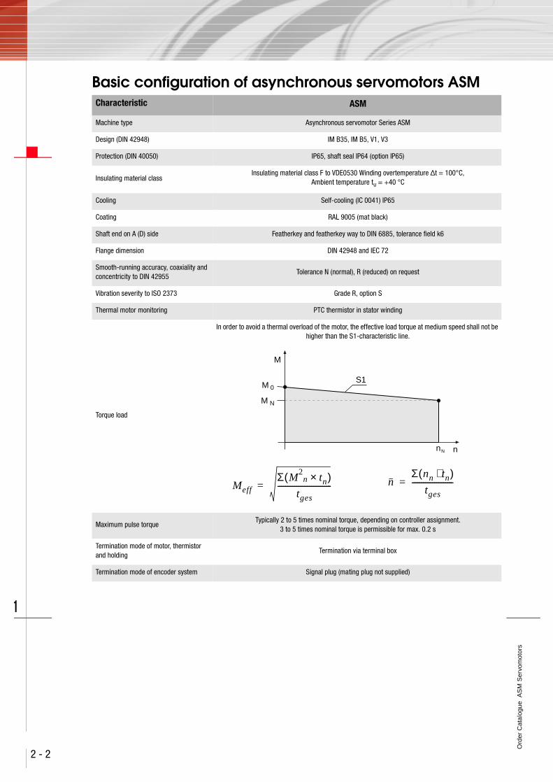
Basic configuration of asynchronous servomotors ASM Characteristic ASM
Machine type Asynchronous servomotor Series ASM
Design (DIN 42948) IM B35, IM B5, V1, V3
Protection (DIN 40050) IP65, shaft seal IP64 (option IP65)
Insulating material classInsulating material class F to VDE0530 Winding overtemperature ∆t = 100°C,
Ambient temperature tu = +40 °C
Cooling Self-cooling (IC 0041) IP65
Coating RAL 9005 (mat black)
Shaft end on A (D) side Featherkey and featherkey way to DIN 6885, tolerance field k6
Flange dimension DIN 42948 and IEC 72
Smooth-running accuracy, coaxiality and concentricity to DIN 42955
Tolerance N (normal), R (reduced) on request
Vibration severity to ISO 2373 Grade R, option S
Thermal motor monitoring PTC thermistor in stator winding
Torque load
In order to avoid a thermal overload of the motor, the effective load torque at medium speed shall not be higher than the S1-characteristic line.
Maximum pulse torqueTypically 2 to 5 times nominal torque, depending on controller assignment.
3 to 5 times nominal torque is permissible for max. 0.2 s
Termination mode of motor, thermistor and holding
Termination via terminal box
Termination mode of encoder system Signal plug (mating plug not supplied)
M 0
NM
M
S1
nN n
MeffΣ M
2n tn×( )
tges-----------------------------= n
Σ nn tn⋅( )tges
----------------------=

Ord
er C
atal
ogue
AS
M S
ervo
mot
ors
2 - 3
1
Order code for asynchronous servomotors ASM
AS M 3 4 - 2 0 R2 1 - 0
Asynchronous servomotor
Motor type
Design: flange, self-coolingDesign: flange, forced coolingDesign: flange and foot, self-coolingDesign: flange and foot, forced cooling
MFHV
Design / Cooling type
Flange 110 x 110 mmFlange 140 x 140 mmFlange 190 x 190 mmFlange 260 x 260 mm
1234
Flange size
Length 1Length 2Length 3Length 4Length 5
1234 5
Length
3 x 190 V3 x 330 V3 x 480 V
124
System voltage
with holding brake permanent-fieldWithout holding brake
10
Holding brake
Resolver 4-poleECN 1313Without encoder
R2G500
Encoder system
1500 rpm2000 rpm3000 rpm
123
Rated speed
Power connection terminal box, encoder straight plug-in 0
Termination technique
Red = preferred type
Motor sizes ASM33 ASM34 ASM41 ASM42 ASM43
Standstill torque 27,5 Nm 42 Nm 47 Nm 70 Nm 85 Nm
Nominal torque 23 Nm 35 Nm 40 Nm 60 Nm 70 Nm
Mains voltage 3 x 400 V
Fitting window 190 mm 260 mm

Ord
er C
atal
ogue
AS
M S
ervo
mot
ors
2 - 4
1
Typical torque characteristic of asynchronous servomotors ASM
Cooling The specified nominal data relate to a max.ambient temperature of 40 °C and mounting ofthe motor on an aluminium plate with a max.temperature of 40 °C and installed at an alti-tude of max. 1000 m above MSL.
Minimum mounting area:2.5 x area of motor flange
Thickness of mounting area:min. 10 mm
If the motor is mounted with insulation (no heatdischarge via the flange) the nominal torquemust be reduced.
For installations above an altitude of > 1000 mabove MSL the power output must be reducedby 1 % per 100 metres. The maximum installa-tion altitude is 4000 metres. At ambient tempe-ratures > 40 °C the power output must bereduced by 1 % per 1 °C. The maximum ambi-ent temperature is 50 °C.
Term Explanation
M0 Standstill torque Thermal limit torque of the motor at standstill. The motor can deliver this torque for an unlimited length of time.
I0 Standstill current Effective value of the motor phase current required to generate the standstill torque.
MN Rated torque Thermal limit torque of the motor at rated speed nN.
IN Rated current Effective value of the motor phase current required to generate the nominal torque.
PN Rated powerContinuous power output of the motor at the nominal operation point (MN, nN)
at rated current IN and rated voltage UN.
Mmax, Imax Limit characteristic A maximum of five times the rated current may be applied to the motors.
Field weakening rangeThe maximum peak torque output in the field weakening range depends on the voltage reserve. The typical torque characteristic is proportional to the function 1/f or 1/n respectively.
5
4
3
2
1 2 3n
M0
NM
NMM
maxM
4
N
nnN
Depending on voltage reserve
Intermittent
M~n1
Field weakening range
max 0.2sPulsed
Continuous

Ord
er C
atal
ogue
AS
M S
ervo
mot
ors
2 - 5
1
Selection list for preferred servomotor - servocontroller
Technical Data asynchronous servomotors ASM for 400 V
Other motor types on request.
Fitting window[mm]
Motor typeStandstill
torqueM0 [Nm]
Rated torque
MN [Nm]
Rated speed nN
[rpm]
Servo-controller1)
Rated current
O2)
190 x 190 ASM33-20R21-0 27,5 23,0 1500CDD/CDE34.010
10 2,1
190 x 190 ASM34-20R21-0 42,0 35,0 1500CDD/CDE34.014
14 2,0
260 x 260 ASM41-20R21-0 47,0 40,0 1500CDD/CDE34.024
24 2,4
260 x 260 ASM42-20R21-0 70,0 60,0 1500CDD/CDE34.032
32 2,3
260 x 260 ASM43-20R21-0 85,0 70,0 1500CDD/CDE34.032
32 1,9
1) Assigned servocontroller with rating 1:1 (motor rated current ≤ servocontroller rated current)
2) O = Overload capacity of system
DesignationM0
[Nm]MN
[Nm]PN
[kW]I0
[A]IN
[A]
nN
[min-1]
nmax
[min-1]
JL [kgcm²]
l [mm]m
[kg]
ASM33-20R21-0 27,5 23 3,6 10,3 8,7 1500 8000 130 387 41,5
ASM34-20R21-0 42,0 35 5,5 15,1 12,6 1500 8000 209 482 56,6
ASM41-20R21-0 47,0 40 6,3 21,0* 17,9* 1500 8000 450 408 87
ASM42-20R21-0 70,0 60 9,4 30,0 25,5 1500 8000 740 498 113
ASM43-20R21-0 85,0 70 11,0 37,0 30,4 1500 8000 960 568 135
* UN = 310 V
Stan
dstil
l tor
que
Nom
inal
torq
ue
Rate
d po
wer
Stan
dstil
l cur
rent
Rate
d cu
rren
t
Nom
inal
spe
ed
Max
. per
m. s
peed
Mom
ents
of i
nert
iaof
roto
r
Over
all l
engt
h
Mas
s

Ord
er C
atal
ogue
AS
M S
ervo
mot
ors
2 - 6
1
Termination technique
Diagram Power connection Encoder connection
Power connection via terminal box
Contact pins for 12-pole junction box: ∅ 1 mm
Ring size:
ASM = M6
PTC/Brake = M3
1/2 -Thermal protection PTC
BR - Holding brake (option)
U,V,W - Motor
- Ground
1 - SIN- (S4)
2 - COS+ (S1)
5 - REF+ (R1)
7 - REF- (R2)
10 - SIN+ (S2)
11 - COS- (S3)
9 - vacant
12 - vacant
3,4,6,8 - vacant
+ –
1
2
U V W
BR BR2
U V W
1
2
34
56
7
89
10 P
11
12
Resolver

Ord
er C
atal
ogue
AS
M S
ervo
mot
ors
2 - 7
1
Ready made-up encoder cables
Technical Data:
Encoder cable KRY-KS-005
K RY - KS 005
Encoder cable
Ready made-up cable
Resolver Encoder cable SSI or ECN1313
RYGS
Encoder system
Festoon-compatible KS
Version
Length 2 mLength 3 mLength 5 mLength 8 mLength 10 mLength 15 mLength 20 m
002003005008010015020
Cable length
KRY-KSxxx KGS-KSxxx
Servocontroller type CDD/CDE3000
Motors with encoder system ResolverG5 (single- or multi-turn encoder with SSI
interface)
Festoon-compatible ja
Minimum bending radius:in fixed installation
in flexible use
-
90 mm
40 mm
100 mm
Temperature range:in fixed installation
in flexible use -40 ... +85 °C
-35 ... +80 °C
-35 ... +80 °C
Cable diameter approx. 8.8 mm 8.0 mm
Material of outer sheath PUR PUR
ResistanceResistant to oil, hydrolysis and microbic attack
(VDE0472)Resistant to oil, hydrolysis and microbic
attack (VDE0472)
Approvals
UL-Style 20233,80 °C - 300 V,
CSA-C22.2N.210-M90, 75 °C - 300 V FT1
-
Ord
er C
atal
ogue
AS
M S
ervo
mot
ors
2 - 8
1

Bes
tellk
atal
og A
SM
-Ser
vom
otor
en
Ord
er C
atal
ogue
AS
M S
ervo
mot
ors
Alles für Ihren Erfolg
Everything for your success
www.lust-tec.de
Servo- undUmrichterantriebssysteme
für die Automation
www.lust-tec.de
Servo and inverter drive systems for automation
www.lust-drivetronics.deServoantriebssysteme für dieAutomation
www.lust-drivetronics.deServo drive systems for automation
www.levitec.comMotor- und Magnetlagerkomponenten für hochtourige Antriebe
www.levitec.comMotor and magnetic bearing componentsfor high-speed drives
www.sensitec.comMagneto-resistive sensor-Chips und Mikrosysteme für die Messung physikalischer Größen
www.sensitec.comMagneto-resistive sensor chipsand microsystems for measuringphysical variables
www.naomi-mainz.deState-of-the-Art Chip-Großserienproduktion für AMR- und GMR-Sensoren
www.naomi-mainz.deState-of-the-art large-scalechip production for AMR and GMR sensors
www.lust-hybrid.deAufbau- und Verbindungstechnik für Mikrosysteme
www.lust-hybrid.deAssembly and interconnectiontechnology for microsystems
D R I V ET R O N I C S

Lust Antriebstechnik GmbHGewerbestrasse 5-9 35633 LahnauTel. 0 64 41 / 9 66-0Fax 0 64 41 / 9 [email protected]
Lust DriveTronics GmbHHansastraße 120D-59425 UnnaTel. 0 23 03 / 77 9-0Fax 0 23 03 / 77 9-3 [email protected]
D R I V ET R O N I C S
Id.-
No.
: 081
4.04
B.1
-00
• 1
0/20
04
Technische Änderungen vorbehalten.
Ord
er C
atal
ogue
AS
M S
ervo
mot
ors
We reserve the right to make technical changes.
Bes
tellk
atal
og A
SM
-Ser
vom
otor
en