asme a18.1.2008 asme a18.1.2008.pdf - internet archive
TRANSCRIPT

NOTICE OF INCORPORATIONUnited States Legal Document
≠ All citizens and residents are hereby advised that this is a legally binding document duly incorporated by reference and that failure to comply with such requirements as hereby detailed within may subject you to criminal or civil penalties under the law. Ignorance of the law shall not excuse noncompliance and it is the responsibility of the citizens to inform themselves as to the laws that are enacted in the United States of America and in the states and cities contained therein. ±
«

Safety Standard for Platform Lifts and Stairway Chairlifts
AN AMERICAN NATIONAL STANDARD
Copyright © 2008 by the American Society of Mechanical Engineers. ~ No reproduction may be made of this material without written consent of ASME. ~

Safety Standard for Platform Lifts and Stairway Chairlifts
AN AMERICAN NATIONAL STANDARD
Copyright © 2008 by the American Society of Mechanical Engineers. ~ No reproduction may be made of this material without written consent of ASME. ~
Date of Issuance: August 28, 2008
The next edition of this Standard is scheduled for publication in 2011. This Standard will become effective 6 months after the Date of Issuance. There will be no addenda issued to this edition.
ASME issues written replies to inquiries concerning interpretations of technical aspects of this Standard. Interpretations are published on the ASME Web site under the Committee Pages at http://www.asme.org/codes/ as they are issued.
ASME is the registered trademark of The American Society of Mechanical Engineers.
This code or standard was developed under procedures accredited as meeting the criteria for American National Standards. The Standards Committee that approved the code or standard was balanced to assure that individuals from competent and concerned interests have had an opportunity to participate. The proposed code or standard was made
available for public review and comment that provides an opportunity for additional public input from industry, academia, regulatory agencies, and the pUblic-at-large.
ASME does not "approve," "rate," or "endorse" any item, construction, proprietary device, or activity. ASME does not take any position with respect to the validity of any patent rights asserted in connection with any
items mentioned in this document, and does not undertake to insure anyone utilizing a standard against liability for infringement of any applicable letters patent, nor assumes any such liability. Users of a code or standard are expressly advised that determination of the validity of any such patent rights, and the risk of infringement of such rights, is entirely their own responsibility.
Participation by federal agency representative(s) or person(s) affiliated with industry is not to be interpreted as government or industry endorsement of this code or standard.
ASME accepts responsibility for only those interpretations of this document issued in accordance with the established ASME procedures and policies, which precludes the issuance of interpretations by individuals.
No part of this document may be reproduced in any form,
in an electronic retrieval system or otherwise, without the prior written permission of the publisher.
The American Society of Mechanical Engineers Three Park Avenue, New York, NY 10016-5990
Copyright © 2008 by THE AMERICAN SOCIE1Y OF MECHANICAL ENGINEERS
All rights reserved Printed in U.S.A.
Copyright © 2008 by the American Society of Mechanical Engineers. No reproduction may be made of this material without \Witten consent of ASME.
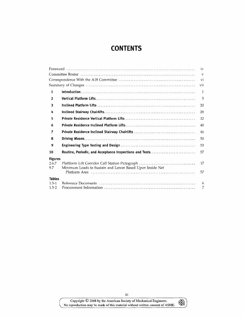
CONTENTS
Foreword . . . . . . . . . . . . . . . . . . . . . . . . . . . . . . . . . . . . . . . . . . . . . . . . . . . . . . . . . . . . . . . . . . . . . . . . . . . . . . iv
Committee Roster ..................................................................... v
Correspondence With the A18 Committee .............................................. vi
Summary of Changes .................................................................. vii
1 Introduction. . . . . . . . . . . . . . . . . . . . . . . . . . . . . . . . . . . . . . . . . . . . . . . . . . . . . . . . . . . . . . . . . . . . . 1
2 Vertical Platform Lifts.. .. . . .. . . . . .. .. .. . .. .. . .. .. .. .. .. . .. .. .. .. .. .. . .. .. . .. .. .. . 5
3 Inclined Platform Lifts. . . . . . . . . . . . . . . . . . . . . . . . . . . . . . . . . . . . . . . . . . . . . . . . . . . . . . . . . . . 20
4 Inclined Stairway Chairlifts. . . . . . . . . . . . . . . . . . . . . . . . . . . . . . . . . . . . . . . . . . . . . . . . . . . . . . . 28
5 Private Residence Vertical Platform Lifts . . . . . . . . . . . . . . . . . . . . . . . . . . . . . . . . . . . . . . . . . . 32
6 Private Residence Inclined Platform Lifts. . . . . . . . . . . . . . . . . . . . . . . . . . . . . . . . . . . . . . . . . . 40
7 Private Residence Inclined Stairway Chairlifts . . . . . . . . . . . . . . . . . . . . . . . . . . . . . . . . . . . . . 46
8 Driving Means. . . . . . . . . . . . . . . . . . . . . . . . . . . . . . . . . . . . . . . . . . . . . . . . . . . . . . . . . . . . . . . . . . . 50
9 Engineering Type Testing and Design. . . . . . . . . . . . . . . . . . . . . . . . . . . . . . . . . . . . . . . . . . . . . 53
10 Routine. Periodic. and Acceptance Inspections and Tests. . . . . . . . . . . . . . . . . . . . . . . . . . . 57
Figures 2.6.7 Plaftform Lift Corridor Call Station Pictograph. . . . . . . . . . . . . . . . . . . . . . . . . . . . . . . . . . 17 9.7 Minimum Loads to Sustain and Lower Based Upon Inside Net
Platform Area ............................................................... 57
Tables 1.5-1 1.5-2
Reference Documents ......................................................... . Procurement Information ...................................................... .
iii
Copyright © 2008 by the American Society of Mechanical Engineers. ~ No reproduction may be made of this material without written consent of ASME. ~
6 7
FOREWORD
This Standard is one of the numerous standards developed and published by The American Society of Mechanical Engineers (ASME) under procedures accredited as meeting the criteria for American National Standards. The consensus committee that approved the Standard was balanced to ensure that individuals from competent and concerned interests have had an opportunity to participate.
This Standard is intended to serve as the basis for state, municipal, and other jurisdictional authorities in drafting regulations governing the installation, testing, inspection, maintenance, alteration, and repair of platform lifts and stairway chairlifts. It is also intended as a standard reference of safety requirements for the guidance of architects, engineers, insurance companies, manufacturers, and contractors, and as a standard of safety practices for owners and management of structures where equipment covered in the Scope of this Standard is used.
This Standard is available for public review on a continuing basis. This provides an opportunity for additional public input from industry, academia, regulatory agencies, and the public-at-large.
Safety codes and standards are intended to enhance public health and safety. Revisions result from committee consideration of factors such as technological advances, new data, and changing environmental and industry needs. Revisions do not imply that previous editions were inadequate.
It should be pointed out that any governmental jurisdiction has authority over any particular installation. Inquiries dealing with problems of a local character should be directed to the proper authority of such jurisdiction. It is recommended that, prior to adoption, all pertinent state and local laws or ordinances be reviewed and where there is a conflict with any of the requirements of this Standard, an exception to such conflicting requirement be noted, quoting the section of the law that applies.
Equipment covered by this Standard was originally incorporated as a 1983 supplement to ANSI! ASME A17.l-l98l, Safety Code for Elevators and Escalators. In ANSI! ASME A17.lb-1983, a new Part XXI covering private residence inclined stairway chairlifts and inclined and vertical wheelchair lifts was added. Part XX was added to cover these same devices installed in buildings other than private residences.
In 1996, as a result of the effort to harmonize the ASME A17.l Code and the CAN/CSA-B44 Safety Code for Elevators, a new Main Committee on Platform Lifts and Stairway Chairlifts was established. The Committee developed the first edition, which incorporates Parts XX and XXI, as well as the applicable cross-references in ASME A17.l-l996, up to and including ASME A17.la-1997.
The first edition of this Standard was approved by The American Society of Mechanical Engineers' Committee on Platform Lifts and Stairway Lifts, was approved and designated as an ASME Standard by the American National Standards Institute on June 21, 1999, and issued on July 26, 1999. The A18.la-200l Addenda was approved on January 30, 200l and issued on March 26, 2001. The A18.lb-200l Addenda was approved on December 11, 200l and issued on April 11, 2002.
The second edition of this Standard was approved by ANSI on July 29, 2003 and was issued on September 12, 2003.
The third edition of this Standard was approved by ANSI on May 6, 2005 and was issued November 29, 2005.
Following approval by the A18 Standards Committee and ASME, and after public review, ASME A18.l-2008 was approved by the American National Standards Institute on July 3, 2008.
iv
Copyright © 2008 by the American Society of Mechanical Engineers. No reproduction may be made of this material without written consent of ASME.
~ ~
ASME AlB COMMITTEE Safety Standard for
Platform Lifts and Stairway Chairlifts (The following is the roster of the Committee at the time of approval of this Standard.)
STANDARDS COMMITTEE OFFICERS
G. L. Harmon, Chair D. W. Boydston, Vice Chair
A. Byk, Secretary
STANDARDS COMMITTEE PERSONNEL
D. C. Balmer, Accessibility Equipment Manufacturer's Association R. Murphy, Alternate, Concord Elevator, Inc. P. D. Barnhart, Underwriters Laboratories, Inc.
J. C. Bovis, Meditek Stairlifts D. W. Boydston, Handi-Lift, Inc. J. Martin, Alternate, Accessibility Lifts, Inc. A. Byk, The American Society of Mechanical Engineers
N. C. Chaitin, McKinley Equipment Corp. W. M. McKinley, Alternate, McKinley Equipment Corp. P. Chance, Elevator Ready, Inc. J. L. Mickel, Alternate, Inclinator Co.
P. Edwards, Integrity Group Cos., Inc. M. A. Sodders, Alternate, American Barrier Solutions, LLC
D. Hallman, DME Access, Inc. G. L. Harmon, National Wheel-O-Vator K. Brinkman, Alternate, National Wheel-O-Vator G. E. Hedman, University of Illinois at Chicago M. K. Mazz, US Access Board S. J. Windley, Alternate, US Access Board M. L. McDonald, Access Disability Advisors, Inc. J. L. Meyer, James Meyer Consulting, Inc. G. L. Nuschler, Otis Elevator
B. Page, Bruno Independent Living Aids T. E. O'Brien, Alternate, Bruno Independent Living Aids C. Rivera, United Spinal Association G. A. Rogers, Elevator Industry Work Preservation Fund S. Z. Sanossian, SZS Consulting T. Shield, T.L. Shield & Associates, Inc. M. Townsend, Garaventa (Canada) Ltd. R. B. Weber, Weber Accessibility System, Inc. E. J. Zuercher, Ascension, A Division of AGM
v
Copyright © 2008 by the American Society of Mechanical Engineers. ~ .. No reproduction may be made of this material without written consent of ASME. ~
CORRESPONDENCE WITH THE A18 COMMITTEE
General. ASME Standards are developed and maintained with the intent to represent the consensus of concerned interests. As such, users of this Standard may interact with the Committee by requesting interpretations, proposing revisions, and attending Committee meetings. Correspondence should be addressed to:
Secretary, A18 Standards Committee The American Society of Mechanical Engineers Three Park Avenue New York, NY 10016-5990
Proposing Revisions. Revisions are made periodically to the Standard to incorporate changes that appear necessary or desirable, as demonstrated by the experience gained from the application of the Standard. Approved revisions will be published periodically.
The Committee welcomes proposals for revisions to this Standard. Such proposals should be as specific as pOSSible, citing the paragraph number(s), the proposed wording, and a detailed description of the reasons for the proposal, including any pertinent documentation.
Interpretations. Upon request, the A18 Standards Committee will render an interpretation of any requirement of the Standard. Interpretations can only be rendered in response to a written request sent to the Secretary of the A18 Standards Committee.
The request for interpretation should be clear and unambiguous. It is further recommended that the inquirer submit his/her request in the following format:
Subject: Edition:
Question:
Cite the applicable paragraph number(s) and the topic of the inqUiry. Cite the applicable edition of the Standard for which the interpretation is being requested. Phrase the question as a request for an interpretation of a specific requirement suitable for general understanding and use, not as a request for an approval of a proprietary design or situation. The inquirer may also include any plans or drawings which are necessary to explain the question; however, they should not contain proprietary names or information.
Requests that are not in this format will be rewritten in this format by the Committee prior to being answered, which may inadvertently change the intent of the original request.
ASME procedures provide for reconsideration of any interpretation when or if additional information that might affect an interpretation is available. Further, persons aggrieved by an interpretation may appeal to the cognizant ASME Committee or Subcommittee. ASME does not "approve," "certify," "rate," or "endorse" any item, construction, proprietary device, or activity.
Attending Committee Meetings. The A18 Standards Committee regularly holds meetings, which are open to the public. Persons wishing to attend any meeting should contact the Secretary of the A18 Standards Committee.
vi
Copyright © 2008 by the American Society of Mechanical Engineers. No reproduction may be made of this material without written consent of ASME.
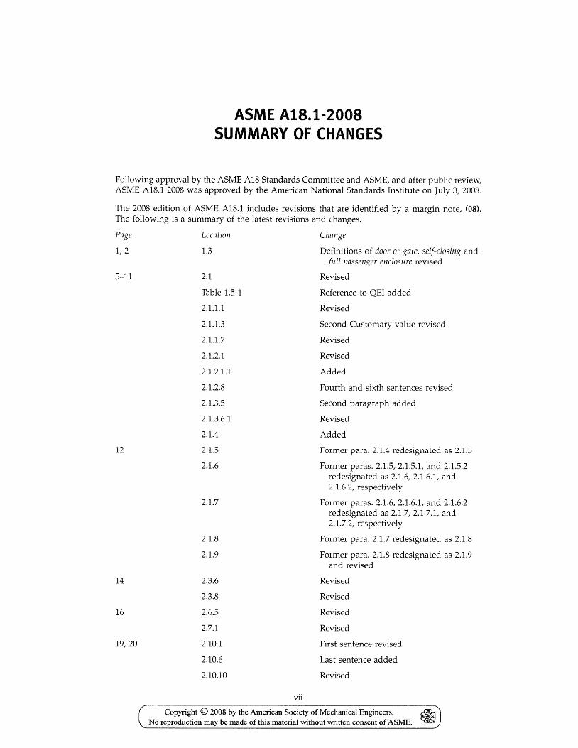
ASME A1B.1-200S SUMMARY OF CHANGES
Following approval by the ASME AlB Standards Committee and ASME, and after public review, ASME A1B.1-200B was approved by the American National Standards Institute on July 3, 200B.
The 200B edition of AS ME A1B.1 includes revisions that are identified by a margin note, (08). The following is a summary of the latest revisions and changes.
Page
1,2
5-11
12
14
16
19,20
Location
1.3
2.1
Table 1.5-1
2.1.1.1
2.1.1.3
2.1.1.7
2.1.2.1
2.1.2.1.1
2.1.2.B
2.1.3.5
2.1.3.6.1
2.1.4
2.1.5
2.1.6
2.1.7
2.1.B
2.1.9
2.3.6
2.3.B
2.6.5
2.7.1
2.10.1
2.10.6
2.10.10
vii
Change
Definitions of door or gate/ self-closing and full passenger enclosure revised
Revised
Reference to QEI added
Revised
Second Customary value revised
Revised
Revised
Added
Fourth and sixth sentences revised
Second paragraph added
Revised
Added
Former para. 2.1.4 redesignated as 2.1.5
Former paras. 2.1.5/2.1.5.1/ and 2.1.5.2 redesignated as 2.1.6/ 2.1.6.1, and 2.1.6.2/ respectively
Former paras. 2.1.6,2.1.6.1, and 2.1.6.2 redesignated as 2.1.7/ 2.1.7.1, and 2.1.7.2, respectively
Former para. 2.1.7 redesignated as 2.1.B
Former para. 2.1.B redesignated as 2.1.9 and revised
Revised
Revised
Revised
Revised
First sentence revised
Last sentence added
Revised
Copyright © 2008 by the American Society of Mechanical Engineers. No reproduction may be made of this material without written consent of ASME.
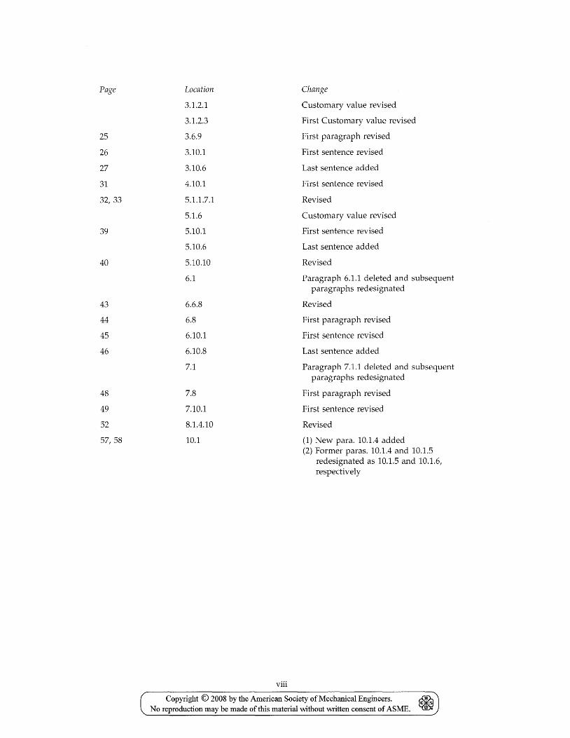
Page Location Change
3.1.2.1 Customary value revised
3.1.2.3 First Customary value revised
25 3.6.9 First paragraph revised
26 3.10.1 First sentence revised
27 3.10.6 Last sentence added
31 4.10.1 First sentence revised
32,33 5.1.1.7.1 Revised
5.1.6 Customary value revised
39 5.10.1 First sentence revised
5.10.6 Last sentence added
40 5.10.10 Revised
6.1 Paragraph 6.1.1 deleted and subsequent paragraphs redesignated
43 6.6.8 Revised
44 6.8 First paragraph revised
45 6.10.1 First sentence revised
46 6.10.8 Last sentence added
7.1 Paragraph 7.1.1 deleted and subsequent paragraphs redesignated
48 7.8 First paragraph revised
49 7.10.1 First sentence revised
52 8.1.4.10 Revised
57,58 10.1 (1) New para. 10.1.4 added (2) Former paras. 10.1.4 and 10.1.5
redesignated as 10.1.5 and 10.1.6, respectively
viii
Copyright © 2008 by the American Society of Mechanical Engineers. ~ No reproduction may be made ofthis material without \Witten consent of ASME. ~
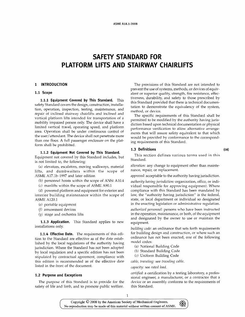
ASME A1B.1-200B
SAFETY STANDARD FOR PLATFORM LIFTS AND STAIRWAY CHAIRLIFTS
1 INTRODUCTION
1.1 Scope
1.1.1 Equipment Covered by This Standard. This safety Standard covers the design, construction, installation, operation, inspection, testing, maintenance, and repair of inclined stairway chairlifts and inclined and vertical platform lifts intended for transportation of a mobility impaired person only. The device shall have a limited vertical travel, operating speed, and platform area. Operation shall be under continuous control of the user / attendant. The device shall not penetrate more than one floor. A full passenger enclosure on the platform shall be prohibited.
1.1.2 Equipment Not Covered by This Standard. Equipment not covered by this Standard includes, but is not limited to, the following:
(a) elevators, escalators, moving walkways, material lifts, and dumbwaiters within the scope of ASME A17.1b-1997 and later edition
(b) personnel hoists within the scope of ANSI AID.4 (c) manlifts within the scope of ASME A90.1 (d) powered platform and equipment for exterior and
interior building maintenance within the scope of ASME A12D.l
(e) portable equipment (j) amusement devices (g) stage and orchestra lifts
1.1.3 Application. This Standard applies to new installations only.
1.1.4 Effective Date. The requirements of this edition to the Standard are effective as of the date established by the local regulations of the authority having jurisdiction. Where the Standard has not been adopted by local regulation and a specific edition has not been stipulated by contractual agreement, compliance with this edition is recommended as of the effective date listed in the front of the document.
1.2 Purpose and Exceptions
The purpose of this Standard is to provide for the safety of life and limb, and to promote public welfare.
1
The provisions of this Standard are not intended to prevent the use of systems, methods, or devices of equivalent or superior quality, strength, fire resistance, effectiveness, durability, and safety to those prescribed by this Standard provided that there is technical documentation to demonstrate the equivalency of the system, method, or device.
The specific requirements of this Standard shall be permitted to be modified by the authority having jurisdiction based upon technical documentation or physical performance verification to allow alternative arrangements that will assure safety equivalent to that which would be provided by conformance to the corresponding requirements of this Standard.
1.3 Definitions (OB)
This section defines various terms used in this Standard.
alteration: any change to equipment other than maintenance, repair, or replacement.
approved: acceptable to the authority having jurisdiction.
authority having jurisdiction: organization, office, or individual responsible for approving equipment. Where compliance with this Standard has been mandated by law, the "authority having jurisdiction" is the federal, state, or local department or individual so designated in the enacting legislation or administrative regulation.
authorized personnel: persons who have been instructed in the operation, maintenance, or both, of the equipment and designated by the owner to use or maintain the equipment.
building code: an ordinance that sets forth requirements for building design and construction, or where such an ordinance has not been enacted, one of the following model codes:
(a) National Building Code (b) Standard Building Code (c) Uniform Building Code
cable, traveling: see traveling cable.
capacity: see rated load.
certified: a certification by a testing laboratory, a professional engineer, a manufacturer, or a contractor that a device or an assembly conforms to the requirements of this Standard.
Copyright © 2008 by the American Society of Mechanical Engineers. ~ No reproduction may be made of this material without written consent of ASME. ~
ASME A1S.1-200S
combination mechanical lock and electric contact: a combination mechanical and electrical device with two related but entirely independent functions, which are
(a) to prevent operation of the driving machine by the normal operating device unless the door or gate is in the closed position
(b) to lock the door or gate in the closed position and prevent it from being opened from the landing side unless the platform is within the specified distance from the landing
compensating-rope sheave switch: a device that automatically causes the electric power to be removed from the driving-machine motor and brake when the compensating sheave approaches its upper or lower limit of travel.
contacts: see door or gate electric contact.
control: the system governing the starting, stopping, direction of motion, acceleration, speed, and retardation of the moving member.
controller: a device or group of devices that serves to control in a predetermined manner the apparatus to which it is connected.
door or gate: the movable portion(s) of the platform or runway entrance that closes the opening providing access to the platform or landing. It consists of one or more panels that may be equipped with a vision panel.
door or gate, manually operated: door or gate that is opened and closed by hand.
door or gate, power-operated: a door or gate that is opened and closed by a door or gate power-operator.
door or gate, self-closing: a manually operated door or gate that closes when released or a power-operated door or gate.
door or gate closer: a device that closes a door or gate by means of a spring or gravity.
door or gate electric contact: an electrical device, the function of which is to prevent operation of the driving machine by the normal operating device unless the door or gate is in the closed position.
door or gate power-operator: a device or assembly of devices that opens a door or gate by power other than by hand, gravity, springs, or the movement of the platform; and that closes them by power other than by hand, gravity, or the movement of the platform.
driving machine: see machine, driving.
emergency stop switch: a device that, when manually operated, causes the lift to halt its motion.
enforcing authority: see authority having jurisdiction.
entrance hardware: all components of an entrance, exclusive of the frame, door panels, and locks, that are necessary to maintain the position of the panels within the assembly.
2
factor of safety: the ratio of the ultimate strength to the working stress of a member under maximum static loading, unless otherwise specified in a particular rule.
full passenger enclosure: an assembly inclusive of the platform top, minimum 2 000 mm (79 in.) tall walls, minimum 2 000 mm (79 in.) tall platform doors and platform floor.
gate: see door or gate.
governor: see speed governor.
governor pull-retarding means: a mechanical means of developing a sufficient force in the governor rope to activate the platform or counterweight safeties or to trip the governor rope releasing carrier, where used. Such mechanical means include, but are not limited to, rope-gripping jaws, clutch mechanisms, and traction arrangements.
governor pull-through tension (jorce): the magnitude of the tensile load developed in the moving governor rope after the governor rope-retarding means is actuated.
inclined platform lift: a powered hoisting and lowering mechanism designed to transport mobility-impaired persons on a guided platform that travels on an incline.
inclined stairway chair lift: a powered hoisting and lowering mechanism that is guided, equipped with a seat, to transport seated passengers along stairways.
inspection and tests acceptance: the initial inspection and tests of new or
altered equipment to check for compliance with the applicable requirements.
periodic: routine inspection and tests plus additional detailed examination and operation of equipment at specified intervals witnessed by an inspector to check for compliance with the applicable requirements.
routine: the examination and operation of equipment at specified intervals by an inspector to check for compliance with the applicable requirements.
installation: a complete platform lift or stairway chairlift, including all machinery and equipment necessary for its operation.
installation, existing: an installation that has been completed or is under construction prior to the effective date of this Standard.
installation, new: any installation not classified as an existing installation by definition, or an existing platform lift or stairway chairlift moved to a new location subsequent to the effective date of this Standard.
installation, placed out of service: an installation whose power feed lines have been disconnected from the machine disconnect switch.
labeled: equipment or materials to which has been attached a label, symbol, or other identifying mark of an independent certifying organization concerned with product evaluation, that maintains periodic inspection
Copyright © 2008 by the American Society of Mechanical Engineers. & No reproduction may be made of this material without written consent of ASME. ~
ASME A18.1-2008
of production of labeled equipment or materials and by whose labeling the manufacturer indicates compliance with appropriate standards or performance in a specified manner.
landing: that portion of a floor, balcony, or platform used to receive and discharge passengers.
landing, bottom terminal: the lowest landing served. landing, top terminal: the highest landing served. landing, unenclosed: a landing that is open to the atmo-
sphere or is open to an interior court of a building.
lever hydraulic driving machine: a hydraulic machine in which the plunger or cylinder is attached to the platform via levers.
listed: equipment or materials included in a list published by an independent certifying organization concerned with product evaluation that maintains periodic inspection of production of listed equipment or materials and whose listing states whether that equipment or material meets appropriate standards or has been tested and found suitable for use in a specified manner.
machine, driving: the power unit that applies the energy necessary to raise and lower equipment covered by the scope of this Standard.
belt-drive machine: an indirect-drive machine equipped with a belt system as the connecting means.
chain-drive machine: an indirect-drive machine with a chain system as the connecting means.
direct-drive machine: an electric driving machine, the motor of which is directly connected mechanically to the driving sheave, drum, or shaft without the use of belts or chains, either with or without intermediate gears.
direct-plunger driving machine: a hydraulic driving machine in which the plunger or cylinder is directly attached to the platform.
electric driving machine: one where the energy is applied by an electric motor. It includes the motor, brake, and the driving sheave or drum together with its connecting gearing, belt, or chain, if any.
friction machine: a direct-drive machine in which the motion of the platform is obtained through friction between a guiding means and driving wheels or rollers.
geared-drive machine: a direct-drive machine in which the energy is transmitted from the motor to the driving sheave, drum, or shaft through gearing.
geared-traction machine: a geared-drive traction machine.
gearless-traction machine: a traction machine, without intermediate gearing, that has the traction sheave and the brake drum mounted directly on the motor shaft.
hydraulic driving machine: one in which the energy is applied by means of a liquid under pressure in a cylinder equipped with a plunger or piston.
indirect-drive machine: an electric driving machine, the motor of which is connected indirectly to the driving
3
sheave, drum, gear reducer, or shaft by means of a belt drive or chain drive.
rack and pinion driving machine: an electric driving machine in which the motion of the platform lift or stairway chairlift is obtained by power-driven rotating pinion(s) mounted on the platform, traveling on a stationary rack mounted in the runway.
roped-hydraulic driving machine: a hydraulic driving machine in which the plunger or piston is connected to the platform with wire ropes or indirectly coupled to the platform by means of wire ropes and sheaves. It includes the cylinder, the plunger or piston, and multiplying sheaves, if any, and their guides.
rope sprocket drive: a driving means consisting of wire rope with fixed links at constant intervals throughout its length. The links engage in slots on a grooved drive cog to provide a positive drive force.
screw machine: an electric driving machine, the motor of which drives a nut on a screw or rotates a screw to raise or lower a platform lift or stairway chairlift.
traction machine: a direct-drive machine in which the motion of a platform is obtained through traction between the suspension ropes and a traction sheave.
winding drum machine: a geared-drive machine in which the suspension ropes are fastened to and wind on a drum.
worm-geared machine: a direct-drive machine in which the energy from the motor is transmitted to the driving sheave or drum through worm gearing.
main floor: the floor providing normal egress from a building.
maintenance: a process of routine examination, lubrication, cleaning, adjustment, and replacement of parts for the purpose of ensuring performance in accordance with the applicable Code requirements.
masonry: built-up construction or combination of building units or materials of clay, shale, concrete, glass, gypsum, stone, or other approved units bonded together with mortar or monolithic concrete. Reinforced concrete is not classed as masonry.
operating device: the switch, pushbutton, lever, or other devices used to actuate the control.
operation: the method of actuating the control. operation, continuous-pressure: operation by means of
buttons or switches on the platform lift or stairway chairlift and on the platform, anyone of which may be used to control the movement of the platform lift as long as the button or switch is manually maintained in the actuating position.
overhead structure: all of the structural members supporting the machinery, sheaves, and equipment at the top of the runway.
penetrate a floor: pass through or pierce a floor in such a way that the opening has a continuous perimeter and
Copyright © 2008 by the American Society of Mechanical Engineers. No reproduction may be made of this material without written consent of ASME.
ASME A1S.1-200S
is provided only to allow the equipment to pass through the floor.
piston: short cylindrical member that is provided with a sealing means that travels with the member within a hydraulic cylinder.
pit: that portion of a runway extending from the sill level of the lowest landing to the floor at the bottom of the runway.
platform: the load carrying unit, including, but not limited to frame, floor, enclosure, seat, and door or gate.
platform frame: a structural frame, composed of interconnecting members, which supports the platform.
plunger (ram): a long cylindrical compression member that is directly or indirectly coupled to the platform frame. This member is not provided with a sealing means. Where used in assembly with a cylinder, the sealing means is provided on the cylinder head, in the case of telescopic plungers and cylinders, a sealing means may be used in the moving plunger that is also a cylinder.
position indicator: a device that indicates the position of the platform in the runway. It is called a hall position indicator when placed at a landing, or a platform position indicator when placed in the platform.
private residence: a separate dwelling or a separate apartment in a multiple dwelling that is occupied only by the members of a single family unit.
rated load: the load that the equipment is designed and installed to lift at the rated speed.
rated load performance: the operation of the equipment with its rated load at rated speed.
rated speed: the speed at which the equipment is designed to operate in the up direction with rated load in the platform.
recycling operation, telescopic plunger: an operation for restoring the relative vertical positions of the multiple plungers in a telescoping plunger arrangement.
releasing carrier, governor rope: a mechanical device to which the governor rope may be fastened, calibrated to control the activation of a safety at a predetermined tripping force.
repair: the process of rehabilitation or replacement of parts that are basically the same as the original for the purpose of ensuring performance in accordance with the applicable Code requirements.
replacement: the substitution of a device or component in its entirety with a new unit that is basically the same as the original for the purpose of ensuring performance in accordance with applicable Code requirements.
rise: see travel.
4
rope, compensating: wire rope used to counterbalance, or partially counterbalance, the weight of the suspension ropes.
rope, counterweight: wire rope used to raise and lower the counterweight on equipment having a winding drum machine or a hydraulic machine equipped with a counterweight.
rope, governor: wire rope with at least one end fastened to the safety activating means or governor rope releasing carrier, passing over and driving the governor sheave, and providing continuous information on the speed and direction of the platform or counterweight.
rope, suspension (hoisting): wire rope used to raise and lower a platform lift or its counterweight, or a stairway chair lift, or both.
rope equalizer, suspension: a device installed on a platform or counterweight to equalize automatically the tensions in the suspension wire ropes.
rope-fastening device, auxiliary: a device attached to the platform or counterweight or to the overhead dead-end rope-hitch support that will function automatically to support the platform or counterweight in case the regular wire-rope fastening fails at the point of connection to the platform or counterweight or at the overhead dead-end hitch.
runby, top, direct-plunger hydraulic: the distance the platform can run above its top terminal landing before the plunger strikes its mechanical stop.
runway: the space in which the platform or seat moves.
runway door or gate, locking device: a device that secures a runway door or gate in the closed position and prevents it from being opened from the landing side except under certain specified conditions.
safety bulkhead: a closure at the bottom of the cylinder located above the cylinder head and provided with an orifice for controlling the loss of fluid in the event of cylinder head failure.
safety, platform or countenoeight: a mechanical device attached to the platform frame or to an auxiliary frame, or to the counterweight frame, to stop and hold the platform or counterweight under one or more of the following conditions: predetermined overspeed, free fall, or if the suspension ropes slacken.
safety, self-resetting: a platform or counterweight safety released and reset by movement in the up direction.
screw column: a structural member provided with screw threads that supports the platform on screw driving machines.
shall: indicates a mandatory requirement.
should: indicates a recommendation, not a mandatory requirement.
Copyright © 2008 by the American Society of Mechanical Engineers. ~ ~ No reproduction may be made of this material without written consent of ASME.
ASME A1B.1-200B
slack-rope switch: a device that automatically causes the electric power to be removed from the driving machine motor and brake when the suspension ropes of a winding drum machine become slack.
sZeeving (liner): the insertion of a smaller diameter cylinder inside the existing cylinder of a hydraulic driving machine.
solid state device: an element that can control current flow without moving parts.
speed governor: a continuously operating speed monitoring and detection device that, at predetermined speeds, provides signals to the controller and imparts a retarding force to activate the platform lift or counterweight safety, or stairway chairlift.
starters control panel: an assembly of devices by means of which the starter may control the manner in which a lift functions.
static switching: switching of circuits by means of solid state devices.
stop switch: see ernergency stop switch.
supply piping: the piping for a hydraulic driving machine between the control valves and the driving member of the driving machine.
terminal landing: see landing.
terminal stopping device, final: a device that automatically causes the power to be removed from the driving machine motor and brake, or from a hydraulic driving machine, independent of the functioning of the normal terminal stopping device, the operating device, or any emergency terminal speed limiting device, after the platform lift or stairway chairlift has passed a terminal landing.
terminal stopping device, machine final (stop-motion switch): a final terminal stopping device operated directly by the driving machine.
terminal stopping device, normal: a device or devices to slow down and stop a platform lift or stairway chairlift automatically at or near a terminal landing independently of the functioning of the operating device.
travel (rise): the vertical distance between the bottom terminal landing and the top terminal landing.
traveling cable: a cable made up of electric conductors, which provides electrical connection between a platform lift or stairway chairlift and a fixed outlet in the runway.
valley break: a broken wire in a wire rope in which the outside wire of a strand breaks in the immediate vicinity of the point where it contacts a wire or wires of an adjacent strand, generally at a point not visible when the wire rope is examined externally. One end of the broken wire is long enough to reach from one valley to the next one and the other end of the broken wire generally cannot be seen.
5
vertical platform lift: a powered hoisting and lowering mechanism designed to transport mobility-impaired persons on a guided platform that travels vertically.
weatherproof so constructed or protected that exposure to the weather will not interfere with its successful operation.
window: an assembly consisting of a surrounding frame and one or more sashes, ventilators, or fixed lights, or a combination of these, designed to be installed in a wall opening for the purpose of admitting light or air, or both.
working pressure: the pressure measured at the cylinder of a hydraulic driving machine when the platform lift or stairway chairlift are lifting their rated load at rated speed.
1.4 Metric (51) Units
This edition of the standard uses hard metric (51) units whenever practical. The acceptable equivalent U.s. Customary units are shown in parenthesis. Information on the usage of 51 units and conversion to U.S. Customary units is contained in IEEEI ASTM 51 10-1997, Standard for the Use of the International System of Units (51): The Modern Metric System, or ASME Guide 51-I, Orientation and Guide for Use of 51 (Metric) Units.
Requirements related to speed and load use the hard metric and hard U.s. Customary units in common practice, even though they are not exactly equivalent.
1.5 Reference Codes, Standards, and Specifications
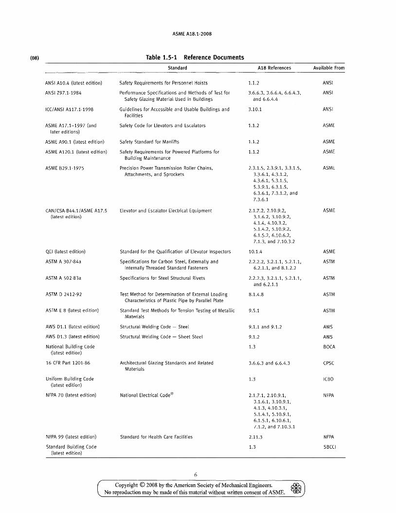
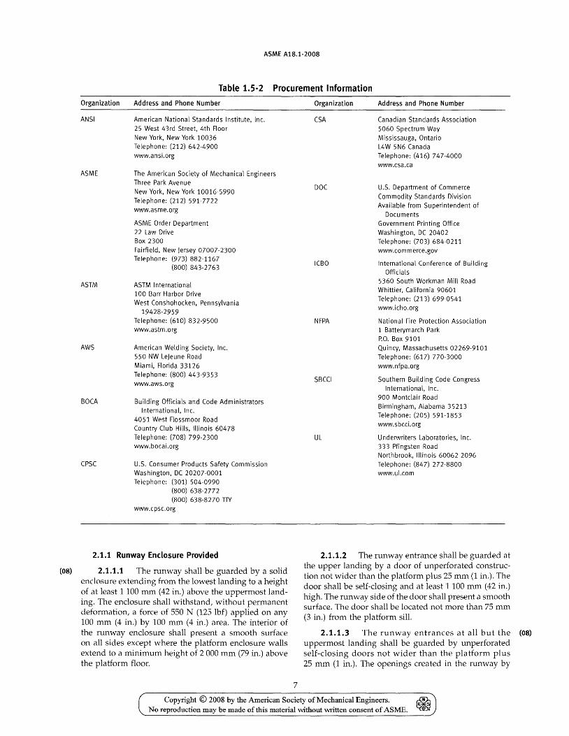
This section covers the codes, standards, and specifications incorporated in this Standard by reference; the specific editions that are applicable; and the rules of this Standard that reference each document (see Table 1.5-1). This section also lists the names and addresses of the organizations from which these documents may be procured (see Table 1.5-2).
Only that portion of the code, standard, or specification as specified by the rules in this Standard is applicable.
2 VERTICAL PLATFORM LlFTSl
Section 2 applies to vertical platform lifts installed in locations other than in or at a private residence for use by the mobility impaired.
2.1 Runways (os)
Runways shall be installed in accordance with para. 2.1.1, 2.1.2,2.1.3, or 2.1.4. Runway construction for lifts that penetrate a floor must comply with para. 2.1.1 and with the building code. Lifts conforming to para. 2.1.4 shall be located in courtroom areas not open to the public and under the supervision of court officials.
1 See section 5 for the requirements for this equipment installed in or at a private residence.
Copyright © 2008 by the American Society of Mechanical Engineers. ~ ~ No reproduction may be made of this material without vvritten consent of ASME.
(OB)
ANSI A10.4 (latest edition)
ANSI Z97.1-1984
ICC/ANSI A117.1-1998
ASME A17.1-1997 (and later editions)
ASME A90.1 (latest edition)
ASME A120.1 (latest edition)
ASME B29.1-1975
CAN/CSA-B44.1/ASME A17.5 (latest edition)
QEI (latest edition)
ASTM A 307-84a
ASTM A 502-83a
ASTM D 2412-92
ASTM E 8 (latest edition)
AWS D1.1 (latest edition)
AWS D1.3 (latest edition)
National Building Code (latest edition)
16 CFR Part 1201-86
Uniform Building Code (latest edition)
NFPA 70 (latest edition)
NFPA 99 (latest edition)
Standard Building Code (latest edition)
ASME AlB.l-200S
Table 1.5·1 Reference Documents
Standard
Safety Requirements for Personnel Hoists
Performance Specifications and Methods of Test for Safety Glazing Material Used in Buildings
Guidelines for Accessible and Usable Buildings and Facilities
Safety Code for Elevators and Escalators
Safety Standard for Manlifts
Safety Requirements for Powered Platforms for Building Maintenance
Precision Power Transmission Roller Chains, Attachments, and Sprockets
Elevator and Escalator Electrical Equipment
Standard for the Qualification of Elevator Inspectors
Specifications for Carbon Steel, Externally and Internally Threaded Standard Fasteners
Specifications for Steel Structural Rivets
Test Method for Determination of External Loading Characteristics of Plastic Pipe by Parallel Plate
Standard Test Methods for Tension Testing of Metallic Materials
Structural Welding Code - Steel
Structural Welding Code - Sheet Steel
Architectural Glazing Standards and Related Materials
National Electrical Code®
Standard for Health Care Facilities
6
AlS References
1.1.2
3.6.6.3, 3.6.6.4, 6.6.4.3, and 6.6.4.4
3.10.1
1.1.2
1.1.2
1.1.2
2.3.1.5,2.3.9.1,3.3.1.5, 3.3.6.1,4.3.1.2, 4.3.6.1, 5.3.1.5, 5.3.9.1,6.3.1.5, 6.3.6.1, 7.3.1.2, and 7.3.6.1
2.1.7.2, 2.10.9.2, 3.1.6.2,3.10.9.2, 4.1.4, 4.10.3.2, 5.1.4.2, 5.10.9.2, 6.1.5.2, 6.10.6.2, 7.1.3, and 7.10.3.2
10.1.4
2.2.2.2, 3.2.1.1, 5.2.1.1, 6.2.1.1, and 8.1.2.2
2.2.2.3,3.2.1.1, 5.2.1.1, and 6.2.1.1
8.1.4.8
9.5.1
9.1.1 and 9.1.2
9.1.2
1.3
3.6.6.3 and 6.6.4.3
1.3
2.1.7.1,2.10.9.1, 3.1.6.1,3.10.9.1, 4.1.3, 4.10.3.1, 5.1.4.1,5.10.9.1, 6.1.5.1,6.10.6.1, 7.1.2, and 7.10.3.1
2.11.3
1.3
Copyright © 2008 by the American Society of Mechanical Engineers. ~ No reproduction may be made of this material without written consent of ASME. ~
Available From
ANSI
ANSI
ANSI
ASME
ASME
ASME
ASME
ASME
ASME
ASTM
ASTM
ASTM
ASTM
AWS
AWS
BOCA
CPSC
ICBO
NFPA
NFPA
SBCCI
ASME AIB.1-200B
Table 1.5·2 Procurement Information
Organization
ANSI
ASME
ASTM
AWS
BOCA
CPSC
Address and Phone Number
American National Standards Institute, Inc. 25 West 43rd Street, 4th Floor New York, New York 10036 Telephone: (212) 642-4900
www.ansi.org
The American Society of Mechanical Engineers Three Park Avenue
New York, New York 10016-5990 Telephone: (212) 591-7722
www.asme.org
ASME Order Department 22 Law Drive Box 2300 Fairfield, New Jersey 07007-2300 Telephone: (973) 882-1167
(800) 843-2763
ASTM International 100 Barr Harbor Drive West Conshohocken, Pennsylvania
19428-2959 Telephone: (610) 832-9500 www.astm.org
American Welding Society, Inc. 550 NW Lejeune Road Miami, Florida 33126 Telephone: (800) 443-9353 www.aws_org
Building Officials and Code Administrators International, Inc.
4051 West Flossmoor Road Country Club Hills, Illinois 60478 Telephone: (708) 799-2300 www_bocai.org
U.S. Consumer Products Safety Commission Washington, DC 20207-0001 Telephone: (301) 504-0990
(800) 638-2772 (800) 638-8270 TTY
www.cpsc.org
2.1.1 Runway Enclosure Provided
(08) 2.1.1.1 The runway shall be guarded by a solid enclosure extending from the lowest landing to a height of at least 1100 mm (42 in.) above the uppermost landing. The enclosure shall withstand, without permanent deformation, a force of 550 N (125 lbf) applied on any 100 mm (4 in.) by 100 mm (4 in.) area. The interior of the runway enclosure shall present a smooth surface on all sides except where the platform enclosure walls extend to a minimum height of 2 000 mm (79 in.) above the platform floor.
7
Organization
CSA
DOC
I(BO
NFPA
SBCCI
UL
Address and Phone Number
Canadian Standards Association 5060 Spectrum Way
Mississauga, Ontario L4W 5N6 Canada Telephone: (416) 747-4000 www.csa.ca
U.S. Department of Commerce
Commodity Standards Division Available from Superintendent of
Documents Government Printing Office
Washington, DC 20402 Telephone: (703) 684-0211 www.commerce.gov
International Conference of Building Officials
5360 South Workman Mill Road Whittier, California 90601 Telephone: (213) 699-0541 www.icho.org
National Fire Protection Association 1 Batterymarch Park P.O. Box 9101 Quincy, Massachusetts 02269-9101 Telephone: (617) 770-3000
www.nfpa.org
Southern Building Code Congress International, Inc.
900 Montclair Road Birmingham, Alabama 35213 Telephone: (205) 591-1853 www.sbcci.org
Underwriters Laboratories, Inc. 333 Pfingsten Road Northbrook, Illinois 60062-2096 Telephone: (847) 272-8800 www.ul.com
2.1.1.2 The runway entrance shall be guarded at the upper landing by a door of unperforated construction not wider than the platform plus 25 mm (1 in.)_ The door shall be self-closing and at least 1100 mm (42 in.) high. The runway side of the door shall present a smooth surface. The door shall be located not more than 75 mm (3 in.) from the platform sill.
2.1.1.3 The runway entrances at all but the (OB)
uppermost landing shall be guarded by unperforated self-closing doors not wider than the platform plus 25 mm (1 in.). The openings created in the runway by
Copyright © 2008 by the American Society of Mechanical Engineers. No reproduction may be made of this material without written consent of ASME.
ASME A1S.1-200S
these doors shall provide a minimum vertical clearance of 2 000 mm (79 in.). The doors shall guard the entire area of the openings except for space necessary for operation. Space necessary for operation shall reject a ball 12 mm (0.5 in.) in diameter. The lift side of the landing doors and sill shall present a smooth surface located not closer than 10 mm (0.375 in.) nor more than 20 mm (0.75 in.) from the platform floor.
2.1.1.4 All doors shall be provided with a combination mechanical lock and electric contact. Locking devices shall be protected against tampering from the landing side. The locking devices may permit a door to be opened only if the platform floor is within 50 mm (2 in.) of the respective landing. They shall permit the platform to move away from the landing under control of the normal operating device if the door is closed but not locked, provided that the device will cause the platform to stop if it moves away from the landing more than 50 mm (2 in.) before the door is locked. Doors shall withstand, without permanent deformation, a force of 550 N (1251bf) applied on any 100 mm (4 in.) by 100 mm (4 in.) area.
2.1.1.5 No hardware shall project beyond the vertical line of travel of the platform, except for that required for door locks.
2.1.1.6 The running clearance between the entrance and exit sides of the platform floor and the interior of the runway enclosures shall be not less than 10 mm (0.375 in.) nor more than 20 mm (0.75 in.).
(os) 2.1.1.7 Platform sides not used for entrance or exit shall be guarded by enclosure walls of smooth construction to a height of at least 1100 mm (42 in.) above the platform floor with no openings other than those necessary for operation. Openings necessary for operation shall reject a ball 12 mm (0.5 in.) in diameter. A grab rail extending the full length of either sidewall shall be provided at a height of 850 mm (34 in.) to 1000 mm (38 in.). The running clearance between platform enclosure walls that extend less than 2 000 mm (79 in.) above the platform floor and the runway enclosure walls, vertical face of the machine housing, or other rigid surfaces shall be not less than 50 mm (2 in.). The running clearance between platform enclosure walls that extend a minimum of 2000 mm (79 in.) above the platform floor and runway walls or other surfaces shall be not less than 20 mm (0.75 in.). Running clearance between enclosure wall ends and the entrance and exit side of the runway shall be not less than 10 mm (0.375 in.) nor more than 75 mm (3 in.).
2.1.1.8 If the runway enclosure extends to a minimum height of 2 100 mm (84 in.) above the upper landing, consists of transparent walls, is exposed to direct sunlight, and is enclosed with a solid roof, forced ventilation with a minimum air handling capacity of one air
8
change per minute based on net inside enclosure volume shall be provided. The ventilation shall be permitted to be thermostatically controlled, in which case, it shall be set to activate at a temperature not to exceed 32°C (90°F). An auxiliary power source capable of providing the minimum air handling capacity for 1 hr shall be provided. Ventilating fans or blowers, if used, shall be located outside the enclosure, or if inside the enclosure, provide a minimum headroom clearance of 2 100 mm (84 in.).
2.1.2 Partial Runway Enclosure Provided
2.1.2.1 The area under the platform shall be fully (OS)
enclosed by smooth guards, either telescoping or stationary, on all accessible platform sides. The guards shall withstand, without permanent deformation, a force of 550 N (125Ibf) applied on any 100 mm (4 in.) by 100 mm (4 in.) area. The height of stationary guards, if provided, shall be at least equal to the maximum upward travel of the platform floor plus 75 mm (3 in.). The running clearance between the platform enclosure walls and any stationary guard panel, vertical face of the machine housing, or other rigid surfaces shall be not less than 50 mm (2 in.). Shutter-type (telescoping) guards, if provided, shall be securely fastened to the lower landing level and to the platform. Openings necessary for opera-tion of shutter-type (telescoping) guard panels shall reject a ball 12 mm (0.5 in.) in diameter.
2.1.2.1.1 Where stationary guards are used, (OS)
the runway entrance at the lower landing shall be guarded by an unperforated self-closing door. The verti-cal opening created in the runway by this door shall provide a minimum clearance of 2000 mm (79 in.). The horizontal opening created when the door is in its open position, shall not exceed the interior width of the run-way. The door shall guard the entire area of the opening except for space necessary for operation. Space neces-sary for operation shall reject a ball 12 mm (0.5 in.) in diameter. The platform side of the landing door shall present a smooth surface located not less than 50 mm (2 in.) nor more than 75 mm (3 in.) from the platform door. The landing doorsill shall be located not closer than 10 mm (0.375 in.) nor more than 20 mm (0.75 in.) from the platform floor.
2.1.2.2 The runway entrance shall be guarded at the uppermost landing by a door of unperforated construction not wider than the entrance to the platform plus 25 mm (1 in.). The door shall be self-closing and at least 1100 mm (42 in.) high. The door shall be located not more than 75 mm (3 in.) from the platform sill.
2.1.2.3 The runway entrance shall be guarded at any intermediate landing by a door of unperforated construction not wider than the entrance to the platform plus 25 mm (1 in.). The door shall be self-closing and extend to a height of at least 1100 mm (42 in.) above the top terminal landing. The lift side of the door and sill shall present a smooth surface located not closer
Copyright © 2008 by the American Society of Mechanical Engineers. No reproduction may be made of this material without written consent of ASl\1E.

ASME A1B.1-200B
than 10 mm (0.375 in.) nor more than 20 mm (0.75 in.) from the access edge of the platform floor.
2.1.2.4 The side of the platform providing access to the lower landing shall be guarded by a platform door of unperforated construction. The door shall be self-closing and at least 1100 mm (42 in.) high.
2.1.2.5 All doors shall be provided with a combination mechanical lock and electric contact. Locking devices shall be protected against tampering from the landing side. The locking devices shall permit a door to be opened only if the platform floor is within 50 mm (2 in.) of the respective landing. The platform shall be permitted to move away from the landing under control of the normal operating device if the door is closed but not locked, provided that the device will cause the platform to stop if it moves more than 50 mm (2 in.) away from the landing before the door is locked.
2.1.2.6 The platform side of the landing doors and sills shall present a smooth surface and shall not project beyond the vertical line of travel of the platform. No hardware shall project beyond the vertical line of travel of the platform, except for that required for door locks and electric contacts. The doors shall withstand, without permanent deformation, a force of 550 N (125 lbf) applied on any 100 mm (4 in.) by 100 mm (4 in.) area.
2.1.2.7 Smooth vertical fascias of unperforated construction shall be securely fastened from the top terminallanding sill and any intermediate landing sill to the level of the bottom terminal landing sill. They shall be equal to or stronger than 1.5 mm (0.0598 in.) sheet steel and guard the full width of the platform floor. The fascias shall not be permanently deformed when a force of 550 N (125 lbf) is applied on any 100 mm (4 in.) by 100 mm (4 in.) area.
(OB) 2.1.2.8 The platform enclosure walls on the sides not used for entrance or exit shall be of smooth construction to a height of at least 1100 mm (42 in.) above the platform floor with no openings, other than those necessary for operation. Openings necessary for operation shall reject a ball 12 mm (0.5 in.) in diameter. A grab rail extending the full length of either sidewall shall be provided at a height of 850 mm (34 in.) to 1 000 mm (38 in.). The running clearance between the platform enclosure wall and the vertical face of the machine housing shall be not less than 50 mm (2 in.). Where an obstruction or surface less than 1100 mm (42 in.) above the top landing other than machine housing, stationary guard panels, shutter type (telescoping) guard panels or sides used for entering and exiting is within 300 mm (12 in.) of the platform enclosure walls and presents a pinching, shearing, or crushing hazard, a smooth continuous surface shall be provided extending from the lower landing to a height of not less than 1100 mm (42 in.) above the
9
top landing. Where an obstruction or surface is between 1100 mm (42 in.) and 2000 mm (79 in.) above the top landing, a smooth continuous surface shall be provided extending from the lower landing to a height of not less than 75 mm (3 in.) above the obstruction. The continuous surface shall be located on the lift side of the obstruction not closer than 50 mm (2 in.) to the platform enclosure walls.
2.1.3 Runway Enclosure Not Provided
2.1.3.1 The runway entrance shall be guarded at the upper landing by a door of unperforated construction. The door shall be self-closing, at least 1 100 mm (42 in.) high, and withstand, without permanent deformation, a force of 550 N (125 lbf) applied on a 100 mm (4 in.) by 100 mm (4 in.) area. The door shall be located not more than 75 mm (3 in.) from the platform sill.
2.1.3.2 The runway entrance shall be guarded at any intermediate landing by a door of unperforated construction not wider than the entrance to the platform plus 25 mm (1 in.). The door shall be self-closing and extend to a height of at least 1100 mm (42 in.) above the top terminal landing. The lift side of the door and sill shall present a smooth surface located not closer than 10 mm (0.375 in.) nor more than 20 mm (0.75 in.) from the access edge of the platform floor.
2.1.3.3 A smooth vertical fascia shall be provided from the top terminal landing sill and any intermediate landing sill to the level of the bottom terminal landing sill. Openings necessary for operation shall reject a ball 12 mm (0.5 in.) in diameter. A device to stop the platform if an object protrudes beyond the platform edge into the running clearance shall be provided if the fascia is perforated. The device used shall be effective for the full width of the platform opening and for the full travel of the platform. The fascia shall be equal to or stronger than 1.5 mm (0.0598 in.) sheet steel and guard the full width of the platform. The surface shall not be permanently deformed when a force of 550 N (125 lbf) is applied on any 100 mm (4 in.) by 100 mm (4 in.) area.
2.1.3.4 The side of the platform providing access to the lower landing shall be guarded in accordance with the requirements of para. 2.1.3.4.1 or 2.1.3.4.2.
2.1.3.4.1 The lower landing side of the plat-form shall be guarded by a platform door of unperforated construction. The door shall be self-closing, at least 1100 mm (42 in.) high, and withstand, without permanent deformation, a force of 550 N (125Ibf) on a 100 mm (4 in.) by 100 mm (4 in.) area.
2.1.3.4.2 The lower landing side of the platform shall be guarded by a powered, retractable passenger restraining arm(s) conforming to the following:
(a) The arm(s) shall be located above the leading edge of the platform on the lower landing side at a height of
Copyright © 2008 by the American Society of Mechanical Engineers. ~ E ~
No reproduction may be made of this material without written consent of ASME. -
ASME A1B.1-200B
not less than 800 mm (32 in.) or greater than 1000 mm (38 in.). Gaps between the adjacent ends of arm sections or the end of arm sections and the lift sidewall shall not exceed 100 mm (4 in.) when the arms are in their guarding position.
(b) The arm(s) shall be of smooth construction with all edges rounded. They shall not be permanently deformed when a force of 300 N (66 lbf) is applied on any point along the length of the arms in any direction. In addition, they shall not be permanently deformed when a force of 1 000 N (225 lbf) is applied in the horizontal direction along the center line of the platform.
(c) Each retractable arm shall be mechanically locked and monitored by an electric contact, which shall stop the movement of the platform within 50 mm (2 in.) of travel away from any landing if the arm is not in its locked guarding position. Means shall be provided to manually unlock the retractable arm(s) for emergency evacuation purposes. The unlocking mechanism shall not be readily accessible to the passenger.
(d) Control shall be by means of a continuous pressure device. The closing speed shall not exceed 0.3 ml s (1 ftl sec) as measured at the fastest point. The force necessary to prevent closing of the arm(s) shall not exceed 140 N (30 lbf) as measured at the midpoint across the arm at the boarding end of the platform. The arm(s) may operate in the direction away from an obstruction.
(e) A retractable ramp shall be provided in conformance with para. 2.1.5.2.
(08) 2.1.3.5 The sides of the platform not used for entrance or exit shall be guarded by walls of smooth construction with no openings, other than those necessary for the operation of the lift, to a height of at least 1100 mm (42 in.). Those openings necessary for operation shall reject a ball 12 mm (0.5 in.) in diameter. A grab bar extending the full length of either side guard shall be provided at a height of 850 mm (34 in.) to 1000 mm (38 in.).
The running clearance between the platform enclosure walls and the machine housing or any other rigid surface shall be not less than 50 mm (2 in.). Where an obstruction or surface less than 1100 mm (42 in.) above the top landing other than the machine housing is within 300 mm (12 in.) of the platform enclosure walls and presents a pinching, shearing, or crushing hazard, a smooth continuous surface shall be provided extending from the lower landing to a height of not less than 1100 mm (42 in.) above the top landing. Where an obstruction or surface is between 1100 mm (42 in.) and 2000 mm (80 in.) above the top landing, a smooth continuous surface shall be provided extending from the lower landing to a height of not less than 75 mm (3 in.) above the obstruction.
10
2.1.3.6 The underside of the platform shall be guarded in accordance with the requirements of para. 2.1.3.6.1, 2.1.3.6.2, or 2.1.3.6.3.
2.1.3.6.1 The underside of the platform shall be (08) equipped with a device that, if the platform is obstructed anywhere on its underside in its downward travel, shall cause electric power to be removed from the driving machine motor and brake, if provided, and cause the platform to stop its downward motion within 50 mm (2 in.). The stroke of the device shall be not less than the stopping distance of the platform. The force required to operate the device shall not exceed 70 N (15 lbf). The lift shall be permitted to operate away from the obstruction. Downward motion shall be permitted to resume when the obstruction is removed.
2.1.3.6.2 The underside of the platform shall be equipped with a bellows or similar device that shall not be permanently deformed when a force of 550 N (125 lbf) is applied on any 100 mm (4 in.) by 100 mm (4 in.) area. Deflection of the bellows due to a force of 330 N (75Ibf) applied on any 100 mm (4 in.) by 100 mm (4 in.) area shall not exceed 75 mm (3 in.) or the distance to contact an internal moving component other than the bellows support mechanism, whichever is less. Deflection shall be measured with the platform at uppermost landing.
(a) The upper attachment point of the bellows shall be permitted to be inset from the outer edge of the platform provided that the exposed area of the underside of the platform is equipped with a device that conforms to para. 2.1.3.6.1.
(b) Deflection greater than that allowed by para. 2.1.3.6.2 shall be permitted, provided that any additional deflection actuates a sensing device that causes the electric power to be removed from the driving machine motor and brake, if provided, and causes the platform to stop its downward motion within 50 mm (2 in.). Downward motion shall be permitted to resume when the bellows is returned to its normal condition.
2.1.3.6.3 A force sensitive safety surface shall be provided covering the entire floor area directly under the moving platform plus 75 mm (3 in.) beyond any exposed platform edge. The device shall prevent downward motion of the platform when activated by a force not to exceed 70 N (15 lbf) applied anywhere on its surface. The lift shall be permitted to operate in the upward direction. Downward motion shall be permitted to resume when the force is removed.
2.1.3.7 The clearance between the platform floor and the upper landing sill shall be not less than 10 mm (0.375 in.) nor more than 20 mm (0.75 in.).
2.1.3.8 All doors, except as provided in para. 2.1.3.9, shall be provided with a combination mechanical lock and electric contact. Locking devices
Copyright © 2008 by the American Society of Mechanical Engineers. No reproduction may be made of this material without written consent of ASME.
ASME A1S.1-200S
shall be protected against tampering from the landing side. The locking devices shall permit a door to be opened only if the platform floor is within 50 mm (2 in.) of the respective landing. The platform shall be permitted to move away from the landing under control of the normal operating device if the door is closed but not locked, provided that the devices will cause the platform to stop if it moves away from the landing more than 50 mm (2 in.) before the door is locked.
2.1.3.9 Where the lift is installed at a location that does not have guard rails at the upper landing as allowed by building codes (see definition), the requirements of paras. 2.1.3.1,2.1.3.2, and 2.1.3.3 shall be permitted to be omitted when platform gates are provided. They shall extend to a height at least equal to the top terminal landing height plus 150 mm (6 in.) measured when the platform is at its lowest position. The gates shall be of unperforated construction, self-closing, and be provided with electric contacts to prevent movement of the platform if the gates are not closed. The gates shall not be permanently deformed when a force of 550 N (125 lbf) is applied on any 100 mm (4 in.) by 100 mm (4 in.) area.
2.1.3.10 The requirements of para. 2.1.3.7 shall be permitted to be increased to 75 mm (3 in.) if a platform gate complying with para. 2.1.3.9 and an automatically folding ramp to service the upper landing is provided. When deployed, the ramp shall have a minimum overlap at the upper landing sill of 50 mm (2 in.) and shall be substantially level. It shall be provided with an electric contact, which will stop the movement of the platform within 150 mm (6 in.) of travel away from the upper landing if the ramp has failed to rise to its retracted position.
(08) 2.1.4 Courtroom lifts
2.1.4.1 The runway entrance shall be guarded at the uppermost landing by a door of unperforated construction. The door shall be self-closing or power-operated, at a height not less than 900 mm (36 in.), and withstand, without permanent deformation, a force of 550 N (125 lbf) applied on any 100 mm (4 in.) by 100 mm (4 in.) area. The door shall be located not more than 75 mm (3 in.) from the platform sill.
2.1.4.2 Intermediate landing entrances shall be guarded in accordance with the requirements of para. 2.1.4.2.1 or 2.1.4.2.2.
2.1.4.2.1 The runway entrance at any intermediate landing entrance shall be guarded by a self-closing or power-operated door of unperforated construction not wider than the entrance to the platform plus 25 mm (1 in.). The door shall be a minimum height of 150 mm (6 in.) and extend to the top landing plus 75 mm (3 in.). The lift side of the door and sill shall present a smooth surface located not closer than 10 mm (0.375 in.) nor
11
more than 20 mm (0.75 in.) from the edge of the platform floor.
2.1.4.2.2 Any intermediate landing entrance shall be guarded by a self-closing or power-operated guard of smooth, solid construction not wider than the entrance to the platform plus 25 mm (1 in.) and of a height not less than 150 mm (6 in.). The side of the platform facing the intermediate landing shall be provided with a platform-mounted guard of smooth, solid construction, at least the width of the landing entrance and of a height not less than 150 mm (6 in.).
2.1.4.3 The area under the platform shall be fully enclosed by smooth guards, either telescoping or stationary, on all accessible platform sides. The guards shall withstand, without permanent deformation, a force of 550 N (125Ibf) applied on any 100 mm (4 in.) by 100 mm (4 in.) area. Shutter-type (telescoping) guards, if provided, shall be securely fastened to the lower landing level and to the platform. Openings necessary for operation of guards shall reject a ball 12 mm (0.5 in.) in diameter.
2.1.4.4 A vertical fascia shall be provided from the top terminal landing sill and any intermediate landing sill to the level of the bottom terminal landing sill. Openings necessary for operation shall reject a ball 12 mm (0.5 in.) in diameter. The fascia shall guard the full width of the platform. The surface shall not be permanently deformed when a force of 550 N (125 lbf) is applied on any 100 mm (4 in.) by 100 mm (4 in.) area. The clearance between the vertical fascia and platform edge shall be not less than 10 mm (0.375 in.) nor more than 20 mm (0.75 in.).
2.1.4.5 The runway entrance shall be guarded at the lower landing by a door of unperforated construction. The door shall be self-closing or power-operated, at a height not less than 900 mm (36 in.), and withstand, without permanent deformation, a force of 550 N (125Ibf) on a 100 mm (4 in.) by 100 mm (4 in.) area. The clearance between the lower landing door and platform edge shall be not less than 10 mm (0.375 in.) nor more than 20 mm (0.75 in.).
2.1.4.6 The sides of the platform not used for entrance or exit shall be guarded by stationary runway or platform-mounted sidewalls of solid construction with no openings, other than those necessary for the operation of the lift. Those openings necessary for operation shall reject a ball 12 mm (0.5 in.) in diameter. Platform-mounted sidewalls shall be at a height not less than 900 mm (36 in.). The running clearance between a platform-mounted sidewall and stationary surfaces shall be not less than 50 mm (2 in.) nor more than 75 mm (3 in.). Stationary runway sidewalls shall be at a height not less than 900 mm (36 in.) above the lower landing. The clearance between stationary runway sidewalls and
Copyright © 2008 by the American Society of Mechanical Engineers. ~ No reproduction may be made of this material without written consent of ASME. ~
ASME A1S.1-200S
the platform shall be not less than 10 mm (0.375 in.) nor more than 20 mm (0.75 in.).
2.1.4.7 All doors/guards shall be provided with a combination mechanical lock and electric contact. Locking devices shall be protected against tampering from the landing side. The locking devices shall permit a door/guard to be opened only if the platform floor is within 50 mm (2 in.) of the respective landing. The platform shall be permitted to move away from the landing under control of the normal operating device if the door/guard is closed but not locked, provided that the devices will cause the platform to stop if it moves away from the landing more than 50 mm (2 in.) before the door/guard is locked.
(os) 2.1.5 Pipes in Runway Vicinity. Pipes conveying steam, gas, or liquids that, if discharged into the runway, would endanger life or health shall not be permitted.
(OS) 2.1.6 Lower Level Access Ramps and Pits. Lifts shall be permitted to have a pit. Unenclosed pits shall not exceed 100 mm (4 in.) in depth. Where a pit is not provided, a floor-mounted or retractable platform floor-mounted ramp shall be provided in accordance with para. 2.1.6.1 or 2.1.6.2.
2.1.6.1 Ramping inclinations for floor-mounted ramps shall be not greater than
(a) 1 in 8 for heights up to 75 mm (3 in.) (b) 1 in 10 for heights up to 100 mm (4 in.) (c) 1 in 12 for heights greater than 100 mm (4 in.)
2.1.6.2 Retractable ramps shall be automatically actuated to a position of 70 deg minimum from horizontal and shall remain in their elevated position until the platform returns to the landing. When in use, the inclination of the ramps shall be not greater than
(a) 1 in 4 for heights up to 50 mm (2 in.) (b) 1 in 6 for heights up to 65 mm (2.5 in.) (c) 1 in 8 for heights up to 75 mm (3 in.) (d) 1 in 10 for heights up to 100 mm (4 in.) (e) 1 in 12 for heights greater than 100 mm (4 in.)
(08) 2.1.7 Electrical Equipment and Wiring
2.1.7.1 The installation of electrical equipment and wiring shall conform to the requirements of ANSI/NFPA 70.
2.1.7.2 Electrical equipment shall be certified to the requirements of CAN/CSA B44.1/ ASME A17.5.
(08) 2.1.8 Structural Support. The structure on which the equipment is installed shall be capable of safely supporting the loads imposed.
(08) 2.1.9 Headroom Clearance. Headroom clearance throughout the range of travel shall be not less than 2000 mm (79 in.) as measured vertically from the platform floor.
12
2.2 Guide Rails
Guide rails shall conform to the requirements of paras. 2.2.1 through 2.2.7. Where tee rails are provided they shall also conform to the requirements of paras. 2.2.8 and 2.2.9. Rail joints shall be designed to maintain the accuracy of the rail alignment and to withstand the stress and deflection limitations stipulated in para. 2.2.4.
2.2.1 Material. Guide rails, guide-rail brackets, rail clips, fishplates, and their fastenings shall be of steel or other metals conforming to the requirements of para. 2.2. Where steel may present an accident hazard, as in chemicalor explosive plants, guide rails shall be permitted to be of selected wood or other suitable nonmetallic materials.
2.2.2 Requirements for Steel, Where Used
2.2.2.1 Rails, brackets, fishplates, and rail clips shall be made of open-hearth steel or its equivalent having a tensile strength of not less than 380 MPa (55,000 psi) and having an elongation of not less than 22% in a length of 50 mm (2 in.).
2.2.2.2 Bolts shall conform to ASTM A 307.
2.2.2.3 Rivets shall conform to ASTM A 502.
2.2.3 Requirements for Metals Other Than Steel. Metals other than steel shall be permitted to be used provided the factor of safety is not less than, and the deflections are not more than, the values specified in this section, and provided that cast iron is not used.
2.2.4 Stresses and Deflections
2.2.4.1 Guide Rails. For steels conforming to the requirements of para. 2.2.2, the stresses in a guide rail or in the rail and its reinforcement, due to the horizontal forces imposed on the rail during loading, unloading or running, calculated without impact, shall not exceed 100 MPa (15,000 psi), and the deflection shall not exceed 6 mm (0.25 in.).
Where steels of greater strength than those specified in para. 2.2.2 are used, the stresses specified shall be permitted to be increased proportionately based on the ratio of the ultimate strengths.
2.2.4.2 Brackets, Fastenings, and Supports. The guide-rail brackets, their fastenings and supports, such as building beams and walls, shall be capable of resisting the horizontal forces imposed by rated load with a total deflection to the point of support not in excess of 3 mm (0.125 in.).
2.2.5 Guide-Rail Surfaces. Guide-rail surfaces used for guiding a platform or counterweight shall be sufficiently smooth and true to operate properly with the guiding members. Those surfaces that the platform or counterweight safeties engage shall be smooth and true
Copyright © 2008 by the American Society of Mechanical Engineers. ~ No reproduction may be made of this material without written consent of ASME. ~
ASME A1S.1-200S
within the tolerances required to ensure proper safety application without excessive retardation or excessive out-of-Ievel platform floor conditions resulting.
2.2.6 Overall Length of Guide Rails. The platform and counterweight guide rails shall extend at the top and bottom to prevent the guiding members from disengaging from the guide rails if either the platform or counterweight reaches its extreme limit of travel.
2.2.7 Design and Strength of Brackets and Supports; The building construction forming the supports for the guide rails, and the guide-rail brackets, shall be designed to safely withstand the application of the platform or counterweight safety when stopping the platform and its rated load or the counterweight; and withstand the forces specified in para. 2.2.4.2 within the deflection limits specified.
Where necessary, the building construction shall be reinforced to provide adequate support for the guide rails.
2.2.8 Bracket Fastenings. Guide-rail brackets shall be secured to their supporting structure by means of bolts or rivets, or by welding. Fastening bolts and bolt holes in brackets and their supporting beams shall conform to the requirements of para. 2.2.9. Welding, where used, shall conform to the requirements of para. 9.1.
2.2.9 Fastening of Guide Rails to Rail Brackets. Guide rails shall be secured to their brackets by clips, welds, or bolts. Bolts used for fastening shall be of such strength as to withstand the forces specified in paras. 2.2.4.2 and 2.2.7.
Welding, where used, shall conform to the requirements of para. 9.1.
2.3 Driving Means and Sheaves
The driving means shall be one of the following: (a) winding drum (b) traction (c) roped sprocket (d) chain sprocket (e) screw (f) rack and pinion (g) direct-plunger hydraulic (h) roped-hydraulic (i) lever hydraulic (j) friction Driving means utilizing a combination of two or more
means shall conform to all applicable requirements of the respective means unless stated otherwise.
2 Runway enclosure walls of brick, terra cotta, and similar materials, used in buildings of steel and concrete construction, are usually insufficient in strength to form, by themselves, adequate supports for the guide rails.
13
2.3.1 General Requirements
2.3.1.1 The factor of safety, based on the static load (the rated load plus the weight of the platform, ropes, counterweights, etc.), to be used in the design of driving machines and sheaves, including fasteners transmitting load, shall be not less than 8 for steel, bronze, or other metals having an elongation of less than 14% in a length of 50 mm (2 in.) or 10 for cast iron or other metals having an elongation of less than 14% in a length of 50 mm (2 in.). Other factors of safety for specific driving means are further specified in section 8.
2.3.1.2 Set screws or threaded portions located in the shear plane of bolts and screws shall not be used to transmit load.
Means shall be provided to ensure that there is no relative motion between rigidly-joined components transmitting load.
Where flexible couplings are used to transmit load, means shall be provided to prevent disengagement of the coupling components in the event of failure or excessive motion in the flexible connection.
A fillet shall be provided at any point of change in the diameter of driving-machine shafts and sheave shafts to prevent excessive stress concentrations in the shafts.
Shafts that support drums, sheaves, gears, couplings, and other members, and which transmit torque, shall be provided with tight-fitting keys.
2.3.1.3 Friction gearing, clutch mechanisms, or couplings shall not be used to connect a driving-machine drum or sheave to the main driving mechanism.
2.3.1.4 Worm gearing having cast iron teeth shall not be used on the driving machine.
2.3.1.5 Driving-machine chains and sprockets shall be of steel and shall conform in design and dimensions to the requirements of ANSI! ASME B29.1.
2.3.1.6 Winding drums, traction sheaves, overhead sheaves, and deflecting sheaves used with suspension and compensating ropes shall be of metal, shall be provided with finished grooves for ropes, or shall be permitted to be lined with nonmetallic groove material, and have a pitch diameter of not less than 30 times the diameter of the suspension ropes. Where 8 x 19 steel rope or 7 x 19 steel aircraft cable is used, the pitch diameter of the drums and sheaves shall be permitted to be reduced to 21 times the diameter of the rope or cable.
Where the grooves are used to transmit power, sufficient traction shall be provided between the rope and groove, and in the event of nonmetallic lining failure, between the rope and the remaining sheave groove, to safely stop and hold the platform with 125% of the rated load.
2.3.2 Hydraulic Driving Machines. Direct-plunger hydraulic driving machines, where used, shall conform to the requirements of para. 8.1, except para. 8.1.2.
Copyright © 2008 by the American Society of Mechanical Engineers. No reproduction may be made ofthis material without written consent of ASME.
ASME A1S.1-200S
Roped-hydraulic machines shall also conform to the requirements of para. 8.1 except for paras. 8.1.1, 8.1.3, 8.1.4.3, and 8.1.4.7.
2.3.3 Screw Machines. Screw machines, where used, shall conform to para. 8.2.
2.3.4 Friction Machines. Friction machines, where used, shall conform to para. 8.3.
2.3.5 Machine Framework and Base. The machine framework, base, and fastenings to the buildings where used, shall be of metal construction, have a factor of safety of not less than 5 based on the rated load, and shall be secured in place with support provided to limit their deflections to 6 mm (0.25 in.) maximum in any direction under rated load. Cast iron shall not be used.
(08) 2.3.6 Guarding of Guiding Members. The guiding members shall be guarded to prevent accidental contact. Any opening necessary in guards for operation shall reject a ball 20 mm (0.75 in.) in diameter.
2.3.7 Machinery Beams and Supports
2.3.7.1 All machinery and sheaves shall be so supported and secured to prevent any part becoming loose or displaced. Beams directly supporting machinery shall be of steel or reinforced concrete.
2.3.7.2 Overhead beams and sheaves shall be designed for not less than the total load on overhead beams, which shall be assumed to be equal to the weight of all apparatus resting on the beams plus twice the maximum load suspended from the beams. The load resting on the beams shall include the complete weights of the driving machine, sheaves, controller, etc. The load suspended from the beams shall include the sum of the tensions in all ropes suspended from the beams.
2.3.7.3 The driving machine or sheaves, except idlers or deflecting sheaves with their guards and frames, shall not be fastened to the underside of the supporting beams at the top of the runway.
2.3.7.4 Cast iron in tension shall not be used for supporting members for sheaves where they are hung beneath beams.
(08) 2.3.8 Guarding of Driving Machines and Suspension Means. The driving machine and suspension means shall be guarded to prevent accidental contact. Any opening required for operation shall reject a ball 20 mm (0.75 in.) in diameter. Access shall be provided for inspecting and servicing. Any guard(s) required to be removed for inspecting and servicing shall be screwed, locked, or bolted in place.
2.3.9 Indirect-Drive Machines. Indirect-drive machines, utilizing V-belt drives, tooth drive belts, or drive chains, shall conform to the requirements of
14
paras. 2.3.9.1, 2.3.9.2, and 2.3.9.3, except that the requirements of para. 2.3.9.2 shall be permitted to be omitted if a self-locking drive meeting the requirements of para. 2.4.3 is provided. If multiple belts or chains are provided, they shall be preloaded and matched for length in sets.
2.3.9.1 General Requirements. Belt sets shall be selected on the basis of the manufacturer's rated breaking strength and a factor of safety of 10. Chain and sprocket sets shall be selected on the basis of recommendations set forth in the Supplementary Information section of ANSI! ASME B29.1, using a service factor of 2. Offset links in chain are not permitted.
Sprockets in a chain drive set and also a driven set shall be assembled onto a common hub, with teeth cut in-line after assembly to ensure equal load distribution on all chains. Tooth sheaves for a belt drive shall be constructed in a manner to ensure equal load distribution on each belt in the set. Load determination for both the belt and chain sets shall be based on the maximum static loading on the platform, which is the full load in the platform at rest and at a position in the runway that creates the greatest load, including either the platform or counterweight resting on its buffer.
Chain drives and belt drives shall be guarded to protect against accidental contact and to prevent foreign objects from interfering with drives.
2.3.9.2 Monitoring and Brake Location. Each belt or chain in a set shall be continuously monitored by a broken belt or chain device that shall function to automatically interrupt power to the machine and apply the brake if any belt or chain in the set breaks or becomes excessively slack. The driving machine brake shall be located on the traction sheave or drum assembly side of the driving machine so as to be fully effective if the entire belt set or chain set should break.
2.3.9.3 Replacement of Belts or Chains. If one belt or chain of a set is worn, stretched, or damaged so as to require replacement, the entire set shall be replaced. Sprockets and toothed sheaves shall also be replaced if worn.
2.4 Driving Machine Brakes
2.4.1 Driving machines, except hydraulic, shall be equipped with friction brakes directly attached to the driving means through a continuous shaft, mechanical coupling, or toothed gearing applied by springs, or by gravity, and released electrically.
2.4.2 A single ground or short circuitl a counter voltage or a motor-field discharge shall not prevent the brake magnet from allowing the brake to set when the operating device is placed in the stop position.
2.4.3 A machine brake is not required if a self-locking drive utilizing a lead screw, worm, or other
Copyright © 2008 by the American Society of Mechanical Engineers. & No reproduction may be made oftms material without written consent of ASME. ~
ASME A1S.1-200S
positive gearing that will stop and hold the platform with the rated load within 100 mm (4 in.) of down travel after the power is removed is provided.
2.5 Suspension and Support Means
2.5.1 General Requirements
2.5.1.1 Suspension and support means shall be one or more of the following:
(a) steel or iron wire rope (b) steel aircraft cable (c) chain (d) hydraulic (e) rack and pinion if) screw (g) friction machine guides and rollers (ll) lever Suspension and support means utilizing a combina
tion of two or more means shall conform to all applicable requirements of the respective means unless stated otherwise.
2.5.1.2 Steel tapes or welded link chains shall not be used as suspension means.
2.5.1.3 Where ropes or chains are used, no fewer than two shall be provided.
2.5.1.4 For rated loads up to 230 kg (500 lb), ropes shall have a minimum diameter of 6 mm (0.25 in.) and chains shall have a minimum pitch of 12 mm (0.5 in.). For higher rated loads, ropes shall have a minimum diameter of 10 mm (0.375 in.) and chains shall have a minimum pitch of 15 mm (0.625 in.).
2.5.2 Factors of Safety. The suspension and support means shall have a factor of safety of not less than 7 based on the tension or forces exerted on the suspension and support means when raising the rated load. When the platform and counterweight are suspended by steel ropes and the driving means between the machine and the counterweight is an endless roller-type chain, the factor of safety of such chain shall be not less than 8, based on the rated load. See section 8 for special requirements for particular drive systems.
2.5.3 Arc of Contact of Suspension Means on Sheaves and Sprockets. The arc of contact of a wire rope on a traction sheave shall be sufficient to produce adequate traction under all load conditions. The arc of contact of a chain on a driving sprocket shall be not less than 140 deg.
2.5.4 Spare Rope Turns on Winding Drums. All wire ropes of winding drum machines shall have not less than one full turn of the rope on the drum when the platform or counterweight has reached its limit of possible overtravel.
2.5.5 Securing Suspension Ropes to Winding Drums. The drum ends of wire ropes shall be secured
15
on the inside of the drum of winding drum machines by clamps or by tapered babbitted sockets, or by other means approved by the authority having jurisdiction.
2.5.6 Lengthening, Splicing, Repairing, or Replacing Suspension Means. Suspension ropes shall not be lengthened or repaired by splicing. Broken or worn suspension chains shall not be repaired. If one rope or chain of a set is worn or damaged and requires replacement, the entire set of ropes or chains shall be replaced. If a chain or sprocket is replaced due to wear, all chains and sprockets shall be replaced.
2.5.7 Fastening of Rope Suspension Means to Platform. The platform ends of wire ropes shall be fastened in a return loop by properly made individual tapered babbitted sockets or properly attached fittings as recommended by wire rope manufacturers. Clips of the U-bolt type shall not be used. Tapered babbitted rope sockets and the method of babbitting shall conform to the requirements of para. 9.8.
2.5.8 Guarding. All suspension means shall be guarded against accidental contact. Suspension means that operate within a guide or track and travel at the same speed and in the same direction as the platform shall be considered suitably guarded.
2.6 Platforms
2.6.1 Frame and Floor. The frame shall be of metal construction and have a factor of safety of not less than 5 based on the rated load. The floor shall be of metal or wood construction with a nonskid surface.
2.6.2 Securing of Enclosures. The enclosure shall be securely fastened to the floor and so supported that it cannot loosen or become displaced in ordinary service, on the application of the platform safety, or on buffer engagement. The enclosure shall be so constructed that removable portions cannot be dismantled from within the platform.
Enclosure linings, decorative panels, light fixtures, and other apparatus or equipment attached to the enclosure shall be securely fastened and so supported that they will not loosen or become displaced in ordinary service, on platform safety application, or on buffer engagement.
Panels attached to the enclosure for decorative or other purposes shall not be unfastened from inside the platform by the use of common tools or shall be permitted to be removed from inside the platform when perforations, exceeding that which would reject a ball 12 mm (0.5 in.) in diameter, in the enclosure used for panel hanging or support have permanent means to prevent straight through passage beyond the running clearance.
2.6.3 Strength and Deflection of Enclosure Walls. The enclosure walls shall be designed and installed to withstand a force of 330 N (75 lbf) applied horizontally
Copyright © 2008 by the American Society of Mechanical Engineers. ~ e s No reproduction may be made of this material without written consent of ASME. m &
ASME A18.1-2008
at any point on the walls of the enclosure wi thout permanent deformation nor cause the deflection to exceed 25 mm (1 in.).
2.6.4 Use of Cast Iron. Cast iron shall not be used in the construction of any load bearing member of the platform frame or floor other than for guide shoes and guide shoe brackets.
(08) 2.6.5 Floor Area. The inside net floor area of lifts conforming to paras. 2.1.1, 2.1.2, and 2.1.3 shall not exceed 1.7 m2 (18 ft2). The inside net floor area of lifts conforming to para. 2.1.4 shall not exceed 2.3 m2 (25 f~).
2.6.6 Illumination
2.6.6.1 At the threshold of the floor, with the landing door open, the minimum illumination shall be not less than 50 Ix (5 fc).
2.6.6.2 During operation, the minimum illumination on the floor and controls shall be not less than 50 Ix (5 fc).
2.6.6.3 An auxiliary illumination source to provide general illumination of not less than 2.2 Ix (0.2 fc) on the floor and controls shall be provided.
The auxiliary system shall be automatically activated when normal illumination power fails and shall be capable of maintaining the above illumination intensity for a period of not less than 4 hr and shall use no fewer than two lamps of approximately equal wattage.
2.6.7 Protection of Platforms Against Fire. For lifts that penetrate a floor, and when fire resistive runway enclosure construction is required by building code, the underside of wood platforms, the exposed surfaces of wood platform stringers, and edges of laminated platforms shall be protected against fire by one of the following methods:
(a) covering with sheet steel of 0.4 mm (0.0164 in.) in thickness or with equally fire-retardant material.
(b) painting with an approved fire-retardant paint having a flame spread rating of not over 50, applied in accordance with the instructions of the manufacturer. Such ratings shall be based on the test procedure specified in ANSI! ASTM E 84.
A pictograph as shown in Fig. 2.6.7 should be posted over each platform lift corridor call station. The pictograph is 125 mm (5 in.) wide and 200 mm (8 in.) high.
2.6.8 A full passenger enclosure shall not be permitted.
2.6.8.1 Platforms shall be permitted to have a top provided the top is non-load-bearing and marked to indicate it cannot sustain a load.
2.7 Capacity, Speed, and Travel
(08) 2.7.1 Limitation of Load, Speed, and Travel. The rated load shall be not less than 200 kg (450 lb) nor more
16
than 475 kg (1,050 lb). Platforms with a floor greater than 1.4 m2 (15 ft2) shall have a rated load of not less than 340 kg (750 Ib). Platforms with a floor greater than 1.7 m2 (18 ft2) shall have a rated load of not less than 475 kg (1,050 lb). The lift shall be capable of sustaining and lowering a load as specified in Fig. 9.7. The rated speed shall not exceed 0.15 ml s (30 ftl min). Travel of lifts conforming to paras. 2.1.1 and 2.1.2 shall not exceed 4250 mm (168 in.). Travel of lifts conforming to para. 2.1.3 shall not exceed 1500 mm (60 in.). Travel of lifts conforming to para. 2.1.4 shall not exceed 600 mm (24 in.).
2.7.2 Capacity Plates. A capacity plate stating the rated load shall be provided by the manufacturer and fastened in a conspicuous place. The letters and numerals used shall be not less than 6 mm (0.25 in.) in height.
2.7.3 Data Plates. A data plate shall be provided by the manufacturer and securely fastened to the machine. The plate shall state the rated speed, rated load, weight of platform, suspension and support means, date of manufacture, and manufacturer's name. Letters and numerals shall be not less than 6 mm (0.25 in.) in height.
2.7.4 Restriction Sign. A sign shall be securely fastened in a conspicuous place at each landing and on the platform. The sign shall state "No Freight" in letters not less than 6 mm (0.25 in.) high and shall include the international symbol of accessibility.
2.8 Safeties and Speed Governors
All platforms shall be provided with a safety, except as permi tted in para. 2.S.8. The safety shall be actuated by the action of a speed governor or by the breakage or slackening of the suspension or support means. Where actuation is by a governor, the safety shall be set at a maximum speed of 0.4 ml s (75 ftl min). Where actuation is by breakage or slackening of the suspension or support means, the safety shall be set without delay, and independent of the speed governor, if provided.
Safety parts shall conform to the requirements of paras. 2.8.2 and 2.8.3. Where hoisting ropes are used, the application of safeties shall conform to the requirements of para. 2.8.4.
The application and release of safeties shall conform to the requirements of paras. 2.8.5, 2.8.6, and 2.8.7.
2.8.1 Screw Drive Machines. When screw drive machines are used, safeties and speed governors conforming to para. 2.8.1 shall be permitted.
2.8.1.1 The down speed of the platform shall be limited, with rated load to not exceed 0.9 mls (175 ftl min) in the event of failure of the driving means.
2.8.1.2 The fall of the platform in the event of failure of the driving nut shall be limited to a distance
Copyright © 2008 by the American Society of Mechanical Engineers. No reproduction may be made of this material without Mitten consent of ASME.
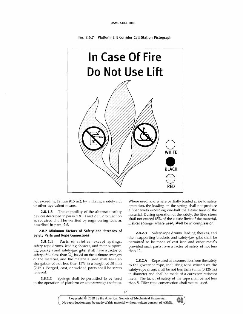
ASME A18.1·2008
Fig. 2.6.7 Platform lift Corridor Call Station Pictograph
In Case Of Fire Do Not Use Lift
not exceeding 12 mm (0.5 in.), by utilizing a safety nut or other equivalent means.
2.8.1.3 The capability of the alternate safety devices described in paras. 2.8.1.1 and 2.8.1.2 to function as required shall be verified by engineering tests as described in para. 9.6.
2.8.2 Minimum Factors of Safety and Stresses of Safety Parts and Rope Connections
2.8.2.1 Parts of safeties, except springs, safety-rope drums, leading sheaves, and their supporting brackets and safety-jaw gibs, shall have a factor of safety of not less than 3~, based on the ultimate strength of the material, and the materials used shall have an elongation of not less than 15% in a length of 50 mm (2 in.). Forged, cast, or welded parts shall be stress relieved.
2.8.2.2 Springs shall be permitted to be used in the operation of platform or counterweight safeties.
17
o WHITE
e BLACK
@ RED
Where used, and where partially loaded prior to safety operation, the loading on the spring shall not produce a fiber stress exceeding one-half the elastic limit of the material. During operation of the safety, the fiber stress shall not exceed 85% of the elastic limit of the material. Helical springs, where used, shall be in compression.
2.8.2.3 Safety-rope drums, leading sheaves, and their supporting brackets and safety-jaw gibs shall be permitted to be made of cast iron and other metals provided such parts have a factor of safety of not less than 10.
2.8.2.4 Rope used as a connection from the safety to the governor rope, including rope wound on the safety-rope drum, shall be not less than 3 mm (0.125 in.) in diameter and shall be made of a corrosion-resistant metal. The factor of safety of the rope shall be not less than 5. Tiller-rope construction shall not be used.
Copyright © 2008 by the American Society of Mechanical Engineers. No reproduction may be made of this material without written consent of ASME.
ASME A1S.1-200S
2.8.2.5 The factors of safety shall be based upon the maximum stresses developed in the parts during the operation of the safety when stopping rated load from governor tripping speed.
2.8.2.6 Safety-rope leading-sheave brackets and other safety operating parts shall not be attached to or supported by wood members.
2.8.3 Material and Factor of Safety. Governor ropes, where provided, shall be of iron, steel, monel metal, phosphor bronze, or stainless steel. They shall be of a regular-lay construction, and not less than 6 mm (0.25 in.) in diameter. The factor of safety of governor ropes shall be not less than 5. Tiller-rope construction shall not be used.
2.8.4 Type A (Instantaneous) Safeties. On the parting of the hoisting ropes (free fall), Type A governor-operated safeties, where provided, shall apply without appreciable delay, and their application shall be independent of the speed action of the governor and of the location of the break in the hoisting ropes (inertia application), and shall be permitted to be accomplished by the use of a governor and governor rigging having a sufficiently high value of inertia to apply the safety on free fall independently of the speed action of the governor.
2.8.5 Means of Application. Safeties shall be applied mechanically. Electric, hydraulic, or pneumatic devices shall not be used to apply the safeties required by section 2, nor to hold such safeties in the retracted position.
2.8.6 Level of Platform Floor on Safety Application. The application of a Type A or Type B safety to stop the platform, with its rated load centered on each quarter of the floor symmetrically with relation to the center line of the floor, shall not cause the floor to be out of level more than 30 mm/ m (0.375 in.! ft) in any direction.
2.8.7 Release. When platform safeties are applied, no decrease in tension in the governor rope nor motion of the platform in the down direction shall release the safeties, but such safeties shall be permitted to be released by the motion of the platform in the up direction.
2.8.8 Platform Safety Exceptions. Platform safeties are not required for lifts with the following driving means:
(a) direct-plunger hydraulic (b) other drives that do not utilize a flexible suspen
sion means, provided that the failure of a single drive component cannot result in the platform overspeeding or the floor going out of level more than 30 mm/m (0.375 in.! ft) in any direction, and said failure would cause the platform to stop by application of a safety switch or equivalent means.
18
2.9 Terminal Stopping Devices
2.9.1 Normal terminal stopping devices required by para. 2.9.2 shall be permitted to use mechanically-operated, magnetically-operated, optical, or static-type switches.
Final terminal stopping devices required by para. 2.9.3 shall use only mechanically-operated switches.
Terminal stopping devices that are located on the platform or in the runway shall be of the enclosed type and securely mounted in such a manner so that horizontal movement of the platform shall not affect the operation of the device.
2.9.2 Normal stopping devices operated by the platform shall be provided, and shall be set to stop the platform floor within a tolerance of 12 mm (0.5 in.) of the landings under rated loading to zero loading conditions. The normal stopping devices shall be permitted to also serve as the upper and lower terminal stopping devices.
2.9.3 Upper and lower final terminal stopping devices operated by the platform shall be provided to remove power from the motor and brake if provided, except as specified in para. 2.9.6. They shall be set to stop the platform after it travels past the normal terminal stopping device and before striking an obstruction. A slack-rope device equipped with a slack-rope switch of the enclosed manually reset type, which shall cause the electric power to be removed from the driving machine motor and brake, if provided, if any hoisting rope becomes slack, shall be permitted as the lower final terminal stopping device.
2.9.4 Final terminal stopping device switch contacts shall be directly opened mechanically. Arrangements that depend on a spring, or gravity, or a combination thereof, to open the contacts shall not be used.
2.9.5 The final terminal stopping device shall not control the same controller switches as the normal stopping device unless two or more separate and independent switches are provided, two of which shall be closed to complete the driving-machine motor-and-brake circuit in either direction of travel. Where a two- or three-phase alternating-current driving-machine motor is used, these switches shall be of the multi-pole type.
The control shall be so designed and installed that a single ground or short circuit shall be permitted to prevent either the normal or final stopping device circuits from stopping the platform, but not prevent both.
2.9.6 Final terminal stopping devices are not required for direct-plunger or roped hydraulic driving machines. Lower final terminal stopping devices are not required where the limitations of the machine or runway limit the travel of the platform (e.g., a platform at rest on the bottom terminal landing).
Copyright © 2008 by the American Society of Mechanical Engineers. ~ No reproduction may be made of this material without written consent of ASME. ~
ASME A1B.1-200B
2.10 Operating Devices and Control Equipment
(08) 2.10.1 Operation. Operation of the lift from the landings and from the platform shall be controlled by control switches at all stations, and shall be by means of the continuous-pressure type. Controls shall be 1 200 mm (48 in.) maximum and 380 mm (15 in.) minimum above the platform floor or facility floor or ground level. Operating devices shall be designed so that both the "UP" and "DOWN" circuits cannot be operated at the same time.
2.10.2 Attendant Operation
2.10.2.1 Where applicable, and where approved by the authority having jurisdiction, the lift shall be permitted to be attendant-operated. The attendant shall be summoned by means of a clearly labeled attendant-call device located at each landing.
2.10.2.2 The attendant shall operate the platform by means of a continuous-pressure switch so located that the attendant has full view of the floor area under the platform and full view of the platform throughout its travel. A manually reset emergency stop switch shall also be provided at that location.
2.10.2.3 No controls, other than an emergency stop switch, shall be provided in the platform.
2.10.3 Control and Operating Circuit Requirements. The design and installation of the control and operating circuits shall conform to the following.
2.10.3.1 Control systems that depend on the completion or maintenance of an electric circuit shall not be used for interruption of the power and application of the machine brake at terminal landings, or for stopping the machine when the safety applies.
2.10.3.2 If springs are used to actuate switches, contactors, or relays to break the circuit to stop the lift at the terminal landings, they shall be of the restrained compression type.
2.10.3.3 The failure of any single magnetically operated switch, relay, or contactor to release in the intended manner, or the failure of any solid state device to operate as intended, or the occurrence of a single accidental ground or combination of accidental grounds shall not permit the lift to start if this failure renders ineffective any electrical protective device.
2.10.4 Motor Reversal Protection. Where a noninstantaneous reversible motor is used, a protective circuit or device shall be provided to prevent the motor from continuing in the same direction if the reversing control is activated.
2.10.5 Phase Reversal and Failure Protection. Lifts having polyphase alternating current power supply shall be provided with means to prevent the starting of
19
the lift motor if the phase rotation is in the wrong direction, or if there is a failure of any phase.
This protection shall be considered to be provided if a reversal of phase of the incoming polyphase alternating current power will not cause the lift driving-machine motor to operate in the wrong direction.
2.10.6 Emergency Stop Switch. An emergency stop (OB) switch shall be provided on the platform and located in or adjacent to each platform operating panel. When opened, this switch shall cause the electric power to be removed from the driving-machine motor and brake if provided.
Emergency stop switches shall be of the manually opened and closed type and have red operating handles or buttons.
They shall be conspicuously and permanently marked "STOP" and indicate the "STOP" and "RUN" positions. Switches shall be positively opened mechanically and their opening shall not be solely dependent on springs.
An emergency stop switch shall not be provided on any landing control, except as required by para. 2.10.2.2.
2.10.7 Slack-Rope and Slack-Chain Devices for Winding Drum and RoUer-Chain-Type Driving Machines. Winding drum driving machines with rope suspension shall be provided with a slack-rope device of the manually reset type that will remove power from the motor and brake if the platform is obstructed in its descent and the suspension ropes slacken. Lifts with roller chain suspension means shall be provided with a slack-chain device that will remove power from the motor and brake if the platform is obstructed in its descent and the suspension means slacken. This device is not required to be of the manually reset type if the chain sprockets are guarded to prevent the chain from becoming disengaged from the sprockets.
2.10.8 Release and Application of Driving-Machine Brake. Driving-machine brakes shall not be electrically released until power has been applied to the driving-machine motor. All power feed lines to the brake shall be opened and the brake shall apply automatically when any operating device in para. 2.10.1 or 2.10.2 is in the stop position, and when any electrical protective device functions.
2.10.9 Electrical Equipment and Wiring
2.10.9.1 All electrical equipment and wiring shall conform to the requirements of ANSI/NFPA 70.
2.10.9.2 Electrical equipment shall be certified to the requirements of CAN /CSA B44.1/ ASME A17.5.
2.10.10 Manual Operations. Means shall be pro- (08)
vided to permit authorized personnel to raise or lower the platform manually in the event of power failure, unless standby (emergency) power is provided. The means to raise or lower the platform shall be capable
Copyright © 2008 by the American Society of Mechanical Engineers. ~ .. No reproduction may be made of this material without written consent of ASME. ~
ASME A18.1-2008
of being accessed and operated without working directly above the platform.
2.11 Emergency Signals
If the platform is installed in an area not visible to personnel at all times, emergency signaling devices shall be provided in accordance with the requirements of para. 2.11.1 or 2.11.2. Standby power shall be provided in accordance with para. 2.11.3.
2.11.1 The platform shall be provided with an audible signaling device, operable from the emergency stop switch, marked also with" ALARM" or from a separate switch marked" ALARM," which is located in or adjacent to each platform operating panel. The switch marked" ALARM" shall illuminate when actuated. The signaling device shall be audible inside the platform and outside the runway. The audible signaling device shall have a rated sound pressure rating of not less than SO dBA nor greater than 90 dBA at 3 000 mm (120 in.) and respond without delay after the switch has been activated.
2.11.2 The lift shall be provided with a means of two-way conversation between the platform and a readily accessible point outside the runway which is available to emergency personnel (telephone, intercom, etc.). The means to activate the two-way conversation system does not have to be provided on the platform.
2.11.3 If the audible signaling device(s), or the means of two-way conversation, or both, are normally connected to the building power supply, they shall automatically transfer to a source of standby or emergency power as required by the applicable building code or, where applicable, Standard for Health Care Facilities (ANSI/NFPA 99) after the normal power supply fails. The power source shall be capable of providing for the operation of the audible signaling device and illumination of the alarm switch for at least 1 hr, and the means of two-way conversation for at least 4 hr.
2.12 Standby Power
Lifts equipped with standby power shall comply with this rule.
2.12.1 Standby Power. Except where permitted by 2.12.1.1, the lift shall be powered by a standby power system from the building.
2.12.1.1 Battery Power. A lift equipped with rechargeable battery power capable of cycling the lift under full load for five cycles minimum after building power is removed shall be permitted.
2.13 Code Data Plate
A data plate shall be provided that indicates the A1S.1 Standard to be used for inspections and tests. The data plate shall be in plain view, securely attached on the
20
main line disconnect or on the controller. The data plate shall be of such material and construction that the letters and figures stamped, etched, cast, or otherwise applied to the face shall remain permanently and readily legible. The height of the letters and figures shall be not less than 3 mm (0.125 in.).
3 INCLINED PLATFORM LlFTS3
Section 3 applies to inclined platform lifts installed in locations other than in or at a private residence for use by the mobility impaired.
3.1 Runways
3.1.1 Means of Egress. Lifts shall be installed so that the means of egress is maintained as required by the authority having jurisdiction.
3.1.2 Clearances. Clearances between the platform and adjacent surfaces shall be not less than 20 mm (0.75 in.). At no point in its travel shall the edge of the platform floor facing the uppermost landing be more than 600 mm (24 in.) above a step or landing as measured vertically.
3.1.2.1 Headroom clearance where the platform (08)
is positioned for boarding shall be not less than 2 000 mm (79 in.) as measured vertically from all points on the surface of the platform floor.
3.1.2.2 Headroom clearance during travel shall be not less than 1 500 mm (60 in.) as measured vertically from any point on the surface of the platform floor.
3.1.2.3 If the headroom is less than 2 000 mm (08)
(79 in.) measured from all points on the platform floor surface throughout its travel a caution sign shall be provided. The caution sign shall contain the words "CAUTION. LOW OVERHEAD" and "SEAT AND SEATBELT PROVIDED." The caution sign shall be securely fastened in a conspicuous place. Letters shall be not less than 6 mm (0.25 in.) high.
3.1.3 Pipes in Runway Vicinity. Pipes conveying steam, gas, or liquid that, if discharged into the runway, would endanger life or health shall not be permitted.
3.1.4 Lower Level Access Ramps and Pits. Lifts shall be permitted to have a pit. Unenclosed pits shall not exceed 100 mm (4 in.) in depth. Where a pit is not provided, a floor-mounted or retractable platform floor-mounted ramp shall be provided in accordance with para. 3.1.4.1 or 3.1.4.2.
3.1.4.1 Ramping inclinations for floor-mounted ramps shall be not greater than
(a) 1 in S for heights up to 75 mm (3 in.)
3 See section 6 for the requirements for this equipment installed in or at a private residence.
Copyright © 2008 by the American Society of Mechanical Engineers. ~ E ~
No reproduction may be made ofthis material without written consent of ASME. ~
ASME A1S.1-200S
(b) 1 in 10 for heights up to 100 mm (4 in.) (c) 1 in 12 for heights greater than 100 mm (4 in.)
3.1.4.2 Retractable ramps shall be automatically actuated and shall remain in their elevated position until the platform returns to the landing. When in use, the inclination of the ramps shall be not greater than
(a) 1 in 4 for heights up to 50 mm (2 in.) (b) 1 in 6 for heights up to 65 mm (2.5 in.) (c) 1 in 8 for heights up to 75 mm (3 in.) (d) 1 in 10 for heights up to 100 mm (4 in.) (e) 1 in 12 for heights greater than 100 mm (4 in.)
3.1.5 Structural Support. The structure on which the lift is installed shall be capable of safely supporting the loads imposed.
3.1.6 Electrical Equipment and Wiring
3.1.6.1 The installation of electrical equipment and wiring shall conform to the requirements of ANSI/NFPA 70.
3.1.6.2 Electrical equipment shall be certified to the requirements of CAN/CSA B44.1/ ASME A17.5.
3.2 Guide Rails and Tracks
3.2.1 Material. Guide rails shall be of metal construction.
3.2.1.1 Requirements for Steel, Where Used. Rails, brackets, fishplates, and rail clips shall be made of open-hearth steel or its equivalent having a tensile strength of not less than 380 MPa (55,000 psi) and having an elongation of not less than 22% in a length of 50 mm (2 in.). Bolts shall conform to ASTM A 307. Rivets shall conform to ASTM A 502.
3.2.1.2 Requirements for Metals Other Than Steel. Metals other than steel shall be permitted to be used provided the factor of safety is not less than, and the deflections are not more than, the values specified in section 3, and provided that cast iron is not used.
3.2.1.3 Guide-Rail Surfaces. Guide-rail surface used for guiding a platform or counterweight shall be sufficiently smooth and true to operate properly with the guiding members. Those surfaces that the platform or counterweight safeties engage shall be smooth and true within the tolerances required to ensure proper safety application without excessive retardation or excessive out-of-Ievel platform conditions resulting.
3.2.2 Location. The top and bottom ends of each run of guide rails shall be so located in relation to the extreme positions of travel of the platform that the platform guiding members cannot travel beyond the ends of the guide rails.
21
3.2.3 Stresses and Deflections of Guide Rails and Their Brackets
3.2.3.1 Guide Rails. For steels conforming to para. 3.2.1.1, the stresses in a guide rail or in the rail and its reinforcement, due to the horizontal forces imposed on the rail during loading, unloading, or running, calculated without impact, shall not exceed 100 MPa (15,000 psi), and the deflection shall not exceed 6 mm (0.25 in.).
Where steels of greater strength than those specified in para. 3.2.1.1 are used, the stresses specified shall be permitted to be increased proportionately based on the ratio of the ultimate strengths.
3.2.3.2 Brackets, Fastenings, and Supports. The guide-rail brackets, their fastenings and supports, such as building beams and walls, shall be capable of resisting the horizontal forces imposed by the rated load with a total deflection at the point of support not in excess of 3 mm (0.125 in.).
3.2.4 Factor of Safety. The factor of safety used in the design of guide rails shall be not less than 5, based on the rated load.
3.2.5 Anchoring. The supporting tracks or guide rails shall be securely anchored to the stairs, floor surface, or sidewall.
3.3 Driving Means and Sheaves
The driving means shall be one of the following: (a) winding drum (b) traction (c) roped sprocket (d) chain sprocket (e) screw if) rack and pinion (g) direct-plunger hydraulic (h) roped-hydraulic (i) lever hydraulic (j) friction
3.3.1 General Requirements
3.3.1.1 The factor of safety, based on the static load (the rated load plus the weight of the platform, ropes, counterweights, etc.), to be used in the design of driving machines and sheaves including fasteners transmitting load, shall be not less than 8 for steel, bronze, or other metals having an elongation of at least 14% in a length of 50 mm (2 in.) or 10 for cast iron or other metals having an elongation of less than 14% in a length of 50 mm (2 in.). Other factors of safety for specific driving means are further specified in section 8.
3.3.1.2 Set screws or threaded portions located in the shear plane of bolts and screws shall not be used to transmit load.
Copyright © 2008 by the American Society of Mechanical Engineers. ~ No reproduction may be made of this material without written consent of ASME. ~

ASME A1S.1-200S
Means shall be provided to ensure that there is no relative motion between rigidly joined components transmitting load.
Where flexible couplings are used to transmit load, means shall be provided to prevent disengagement of the coupling components in the event of failure or excessive motion in the flexible connection.
A fillet shall be provided at any point of change in the diameter of driving-machine shafts and sheave shafts to prevent excessive stress concentrations in the shafts.
Shafts that support drums, sheaves, gears, couplings, and other members, and that transmit torque, shall be provided with tight-fitting keys.
3.3.1.3 Friction gearing, clutch mechanisms, or couplings shall not be used to connect a driving machine drum or sheave to the main driving mechanism.
3.3.1.4 Worm gearing having cast iron teeth shall not be used on the driving machine.
3.3.1.5 Driving-machine chains and sprockets shall be of steel and shall conform in design and dimensions to the requirements of ANSI! ASME B29.1.
3.3.1.6 Winding drums, traction sheaves, overhead sheaves, and deflecting sheaves used with suspension and compensating ropes shall be of metal, be provided with finished grooves for ropes or shall be permitted to be lined with nonmetallic groove material, and have a pitch diameter of not less than 30 times the diameter of the suspension ropes. Where 8 x 19 steel rope or 7 x 19 steel aircraft cable is used, the pitch diameter of the drums and sheaves shall be permitted to be reduced to 21 times the diameter of the rope or cable.
Where the grooves are used to transmit power, sufficient traction shall be provided between the rope and groove, and in the event of nonmetallic lining failure, between the rope and the remaining sheave groove, to safely stop and hold the platform with 125% of the rated load.
3.3.2 Hydraulic Driving Machines. Direct-plunger hydraulic driving machines, where used, shall conform to the requirements of para. 8.1 except para. 8.1.2.
Roped-hydraulic machines shall also conform to the requirements of para. 8.1, except for paras. 8.1.1, 8.1.3, 8.1.4.3, and 8.1.4.7.
3.3.3 Screw Machines. Screw machines, where used, shall conform to para. 8.2.
3.3.4 Friction Machines. Friction machines, where used, shall conform to para. 8.3.
3.3.5 Location of Power Unit and Alignment and Guarding of Sheaves and Sprockets. The power unit shall be permitted to be mounted in the platform or placed at a remote location. If remotely located, all intervening sheaves and sprockets shall be so placed that the rope or chain travels in the proper alignment. All sheaves and sprockets shall be enclosed or guarded.
22
3.3.6 Indirect-Drive Machines. Indirect drive machines, utilizing V-belt drives, tooth drive belts, or drive chains, shall conform to the requirements of paras. 3.3.6.1,3.3.6.2, and 3.3.6.3, except that the requirements of para. 3.3.6.2 shall be permitted to be omitted if a self-locking drive meeting the requirements of para. 3.4.2 is provided. If multiple belts or chains are provided, they shall be preloaded and matched for length in sets.
3.3.6.1 General Requirements. Belt sets shall be selected on the basis of the manufacturer's rated breaking strength and a factor of safety of 10. Chain and sprocket sets shall be selected on the basis of recommendations set forth in the Supplementary Information section of ANSI/ ASME B29.1, using a service factor of 2. Offset links in chain are not permitted.
Sprockets in a chain drive set and also a driven set shall be assembled onto a common hub, with teeth cut in-line after assembly to assure equal load distribution on all chains. Tooth sheaves for a belt drive shall be constructed in a manner to assure equal load distribution on each belt in the set. Load determination for both the belt and chain sets shall be based on the maximum static loading on the platform, which is the full load in the platform at rest and at a position in the runway that creates the greatest load, including either the platform or counterweight resting on its buffer.
Chain drives and belt drives shall be guarded to protect against accidental contact and to prevent foreign objects from interfering with drives.
3.3.6.2 Monitoring and Brake Location. Each belt or chain in a set shall be continuously monitored by a broken belt or chain device that shall function to automatically interrupt power to the machine and apply the brake if any belt or chain in set breaks or becomes excessively slack. The driving machine brake shall be located on the traction sheave or drum assembly side of the driving machine so as to be fully effective if the entire belt set or chain set should break.
3.4 Driving-Machine Brakes
3.4.1 Driving machines, except hydraulic, shall be equipped with electrically-released spring-applied brakes directly attached to the driving means through a continuous shaft, mechanical coupling, or toothed gearing. A single ground or short circuit, a counter voltage, or a motor-field discharge shall not prevent the brake magnet from allowing the brake to set when the operating device is placed in the stop position.
3.4.2 A machine brake is not required if a self-locking drive utilizing a lead screw, worm, or other positive gearing that will stop and hold the platform with the rated load within 100 mm (4 in.) of down travel after the power is removed is provided.
Copyright © 2008 by the American Society of Mechanical Engineers. No reproduction may be made ofthis material without written consent of ASME.
ASME AIB.1-200B
3.5 Suspension and Support Means
3.5.1 General Requirements
3.5.1.1 Suspension and support means shall be one of the following:
(a) steel or iron wire rope (b) steel aircraft cable (c) roller chain (d) direct-plunger hydraulic (e) roped-hydraulic (f) rack and pinion (g) screw (h) friction machine guides and rollers
3.5.1.2 Steel tapes or welded link chains shall not be used as suspension means.
3.5.1.3 Where wire ropes are used, the diameter shall not be less than 6 mm (0.25 in.).
3.5.2 Factors of Safety. The suspension and support means shall have a factor of safety of not less than 7 based on the tension in the rope, cable, chain, or forces exerted on the hydraulic cylinder, screw drive, or rack and pinion when raising the rated load. When the platform and counterweight are suspended by steel ropes and the driving means between the machine and the counterweight is an endless roller-type chain, the factor of safety of such chain shall be not less than 8, based on the rated load. See section 8 for special requirements for particular drive systems.
3.5.3 Arc of Contact of Suspension Means on Sheaves and Sprockets. The arc of contact of a wire rope on a traction sheave shall be sufficient to produce adequate traction under all load conditions. The arc of contact of a chain on a driving sprocket shall be not less than 140 deg.
3.5.4 Spare Rope Turns on Winding Drums. All wire ropes of winding drum machines shall have not less than one full turn of the rope on the drum when the platform or counterweight has reached its limit of possible overtravel.
3.5.5 Securing Suspension Ropes to Winding Drums. The drum ends of wire ropes shall be secured by clamps on the inside of the drum of winding drum machines or by tapered babbitted sockets, or by other means approved by the authority having jurisdiction.
3.5.6 Lengthening, Splicing, Repairing, or Replacing Suspension Means. Suspension wire ropes shall not be lengthened or repaired by splicing. Broken or worn suspension chains shall not be repaired. If one rope or chain of a set is worn or damaged and requires replacement, the entire set of ropes or chains shall be replaced. If a chain or sprocket is replaced due to wear, all chains and sprockets shall be replaced.
23
3.5.7 Fastening of Rope Suspension Means to Platform. The platform ends of wire ropes shall be fastened in a return loop by properly made individual tapered babbitted sockets or properly attached fittings as recommended by wire rope manufacturers. Clips of the U-bolt type shall not be used. Tapered babbitted rope sockets and the method of babbitting shall conform to the requirements of para. 9.8.
3.5.8 Guarding. All suspension means shall be guarded against accidental contact. SuspenSion means that operate within a guide or track and travel at the same speed and in the same direction as the platform shall be considered suitably guarded.
3.6 Platforms
3.6.1 Frame and Floor. The frame shall be of metal construction and have a factor of safety of not less than 5 based on the rated load. The floor shall be of metal or wood construction with a nonskid surface.
3.6.2 Securing of Enclosure. The enclosure shall be securely fastened to the floor and so supported that it cannot loosen or become displaced in ordinary service, on the application of the platform safety, or on buffer engagement. The platform enclosure shall be so constructed that removable portions cannot be dismantled from within the platform.
Enclosure linings, decorative panels, light fixtures, and other apparatus or equipment attached to the enclosure shall be securely fastened and so supported that they will not loosen or become displaced in ordinary service, on platform safety application, or on buffer engagement.
Panels attached to the enclosure for decorative or other purposes shall not be unfastened from inside the platform by the use of common tools or shall be permitted to be removed from inside the platform when perforations, exceeding that which would reject a ball 12 mm (0.5 in.) in diameter, in the enclosure used for panel hanging or support have permanent means to prevent straight through passage beyond the running clearance.
3.6.3 Strength and Deflection of Enclosure Walls. The enclosure walls shall be designed and installed to withstand a force of 330 N (75 lbf) applied horizontally at any point on the walls of the enclosure without permanent deformation nor cause the deflection to exceed 25 mm (1 in.).
3.6.4 Floor Area. The inside floor area shall not exceed 1.1 m2 (12 f0).
3.6.5 Material. Metals having an elongation less than 20% in a length of 50 mm (2 in.) shall not be used in the construction of any member of the frame or floor.
3.6.6 Glass on Platforms. Glass shall be permitted to be used on platforms subject to the following.
Copyright © 2008 by the American Society of Mechanical Engineers. ~ No reproduction may be made of this material without written consent of ASME. ~
ASME A1S.1-200S
3.6.6.1 It shall be installed and guarded so as to provide adequate protection for passengers in case the glass panels break or are dislodged.
3.6.6.2 It shall be so mounted in the structure so that the structure, including the glass in place, shall withstand the required lift tests without damage.
3.6.6.3 Glass greater than 0.1 m2 (1 ft2) in area and abutting panels whose total area is greater than 0.1 m2 (1 ft2
) shall be laminated glass as defined by ANSI Z97.1 or 16 CFR, Part 1201, Section 1201.2 or be glass bonded to a nonpolymeric coating, sheeting, or film backing having a physical integrity to hold the fragments when the glass breaks. Glass shall be tested and conform to the acceptance criteria for laminated glass as specified in ANSI Z97.1 or 16 CFR, Part 1201, Section 1201.4. The glass shall be marked as required by ANSI Z97.1 or 16 CFR, Part 1201, Section 1201.5.
3.6.6.4 Markings as specified in ANSI Z97.1 shall be on each separate piece of glass, and shall remain visible after installation.
3.6.7 Platform Truck and Guides. The platform shall be securely anchored to a truck that supports it. The truck shall be retained in a track or on a guide-rail assembly.
3.6.8 Platform Guarding. Platform guarding shall be in accordance with para. 3.6.8.1, or in accordance with para. 3.6.8.2.
3.6.8.1 Platform With Enclosure. The platform shall be equipped with a self-closing door at least 1 100 mm (42 in.) high on the sides of access to the bottom landing. The door shall be of solid construction and provided with a combination mechanical lock and electric contact and shall only be operable within 50 mm (2 in.) of the bottom landing. It shall be permitted to allow the platform to move if the door or gate is in the closed position, but not locked, provided the device will stop the platform if the door or gate fails to lock before the platform has moved more than 50 mm (2 in.) away from the bottom landing.
The platform enclosure walls on the sides not used for access or exit shall be of smooth construction to a height of 1100 mm (42 in.) above the platform floor with no openings, other than those necessary for operation. Openings necessary for operation shall reject a ball 12 mm (0.5 in.) in diameter. A grab rail extending the full length of either wall shall be provided at a height not less than 850 mm (34 in.) or greater than 1 000 mm (38 in.) from the platform floor. The running clearance between the platform enclosure walls and any adjacent surface shall be not less than 50 mm (2 in.).
3.6.8.2 Platform With Passenger Restraining Arms. A grab rail shall be provided at a height not less
24
than 850 mm (34 in.) or greater than 1000 mm (38 in.) from the platform floor.
3.6.8.2.1 The side of the platform adjacent to the track or guide rail assembly shall be provided with a guard of smooth, solid construction and of height that shall prevent the seated passenger from making accidental contact with moving suspension or driving means or moving platform trucks. The guard shall have no openings other than those necessary for operation. Such openings shall reject a ball 12 mm (0.5 in.) in diameter.
3.6.8.2.2 The nonboarding sides of the plat-form shall be provided with a guard of smooth, solid construction and of a height not less than 6 in. (150 mm).
3.6.8.2.3 The sides of the platform used for boarding shall be provided with retractable metal ramps of a minimum height of 150 mm (6 in.) measured vertically from the surface of the platform floor, locked in their guarding positions. At a landing, only the retractable ramp serving the landing shall be operable. It shall be operable only when the passenger restraining arm at the nonboarding end of the platform is in its locked guarding position. Retractable ramps shall be mechanically locked and monitored by an electric contact, which shall stop the movement of the platform within 50 mm (2 in.) of travel away from the landing if the ramps have failed to rise to their elevated position. Retractable ramps, in their guarding position, shall withstand, without permanent deformation, a force of 550 N (125 lbf) applied on any 100 mm (4 in.) by 100 mm (4 in.) area. This force shall not cause the height of the ramp, at any point in its length, to be less than 150 mm (6 in.) measured vertically from the surface of the platform floor.
3.6.8.2.4 The platform shall be provided with retractable passenger restraining arms conforming to the following:
(a) The arms shall be located above the perimeter of the platform floor at not less than 800 mm (32 in.) or greater than 1000 mm (38 in.). Gaps between the adjacent ends of arm sections shall not exceed 100 mm (4 in.) when the arms are in their guarding positions.
(b) The arms shall be of smooth construction with all edges rounded. They shall not be permanently deformed when a force of 300 N (66 Ibf) is applied on any point along the length of the arms in any direction. In addition, they shall not be permanently deformed when a force of 1 000 N (225 lbf) is applied in the horizontal direction along the center line of the platform.
(c) The arms shall be provided in independent sections. At landings, the retractable ramp and arm at the boarding end of the platform shall be operable only when the arm at the nonboarding end of the platform is in its locked guarding position.
(d) Each retractable arm shall be mechanically locked and monitored by an electric contact, which shall stop
Copyright © 2008 by the American Society of Mechanical Engineers. No reproduction may be made of this material without written consent of AS1\ffi.
ASME A1B.1-200B
the movement of the platform within 50 mm (2 in.) of travel away from any landing if the arm is not in its locked guarding position. Means shall be provided to manually unlock the retractable arms for emergency evacuation purposes. The unlocking mechanism shall not be readily accessible to the passenger.
(e) Where the retractable arms are power operated, control shall be by means of a continuous pressure device. The closing speed shall not exceed 0.3 ml s (1 ftl sec) as measured at the fastest point. The force necessary to prevent closing of power-operated arms shall not exceed 140 N (30 lbf) as measured from rest at the midpoint across the arm at the boarding end of the platform. The arms may operate in the direction away from an obstruction.
(08) 3.6.9 Obstruction Devices. The upward and down-ward facing edges of the platform floor and the entire underside shall be equipped with obstruction devices. The force required to operate the devices shall not exceed 70 N (15 lbf). The obstruction devices shall stop the platform lift from traveling in the direction of the obstruction within a distance of 50 mm (2 in.). The platform lift shall be permitted to operate in the direction away from the obstruction.
The underside obstruction device shall stop the platform lift only when the platform lift is obstructed while traveling in the down direction.
3.6.10 The lift shall be provided with a folding seat and seatbelt with a rated load of not less than 115 kg (250 lb).
3.7 Capacity, Load, Speed, and Angle of Inclination
3.7.1 Limitations of Capacity, Load, and Speed. The capacity shall be one person. The rated load shall be not less than 200 kg (450 lb) and not greater than 340 kg (750 lb). The lift shall be capable of sustaining and lowering a load as specified in Fig. 9.7. The rated speed measured along the incline shall not exceed 0.15 m/ s (30 ft/ min).
3.7.2 Limitation of Angle. No lift shall be installed to operate on an incline greater than 45 deg as measured on the mean.
3.7.3 Capacity Plate. A capacity plate stating the rated load in pounds shall be furnished by the manufacturer and fastened in a conspicuous place on the lift. Letters and numbers shall be not less than 6 mm (0.25 in.) in height.
3.7.4 Data Plates. A data plate shall be provided by the manufacturer and securely fastened in a conspicuous place. The plate shall state the rated speed, rated load, suspension or support means, date of manufacture, and manufacturer's name. Letters and numerals shall be not less than 6 mm (0.25 in.) in height.
25
3.7.5 Restriction Sign. A sign shall be provided at each landing and on the platform and shall be securely fastened in a conspicuous place. The sign shall state "No Freight" in letters not less than 6 mm (0.25 in.) high and shall include the international symbol of accessibili ty.
3.8 Safeties and Speed Governors
All platforms shall be provided with a safety, except platforms of direct-plunger hydraulic lifts. The safety shall be actuated by the action of a speed governor or by the breakage or slackening of the suspension or support means. Where actuation is by a governor, the safety shall be set at a maximum speed of 0.4 m/ s (75 ft/min). Where actuation is by breakage or slackening of the suspension or support means, the safety shall be set without delay, and independent of the speed governor, if provided.
Safety parts shall conform to the requirements of para. 3.8.1. Governor ropes, where provided, shall conform to the requirements of para. 3.8.2. The application and release of safeties shall conform to the requirements of para. 3.8.3.
3.8.1 Minimum Factors of Safety and Stresses of Safety Parts and Rope Connections
3.8.1.1 Parts of safeties, except springs, safety-rope drums, leading sheaves, and their supporting brackets and safety-jaw gibs, shall have a factor of safety of not less than 3~, based on the ultimate strength of the material, and the materials used shall have an elongation of not less than 15% in a length of 50 mm (2 in.). Forged, cast, or welded parts shall be stress relieved.
3.8.1.2 Springs shall be permitted to be used in the operation of platform or counterweight safeties. Where used, and where partially loaded prior to safety operation, the loading on the spring shall not produce a fibre stress exceeding one-half the elastic limit of the material. During operation of the safety, the fibre stress shall not exceed 85% of the elastic limit of the material.
Helical springs, where used, shall be in compression.
3.8.1.3 Safety-rope drums, leading sheaves, and their supporting brackets and safety-jaw gibs, shall be permitted to be made of cast iron and other metals provided such parts have a factor of safety of not less than 10.
3.8.1.4 Rope used as a connection from the safety to the governor rope, including rope wound on the safety-rope drum, shall be not less than 3 mm (0.125 in.) in diameter and shall be made of a corrosion-resistant metal. The factor of safety of the rope shall be not less than 5. Tiller-rope construction shall not be used.
3.8.1.5 The factors of safety shall be based upon the maximum stresses developed in the parts during
Copyright © 2008 by the American Society of Mechanical Engineers. ~ No reproduction may be made of this material without \Witten consent of ASME. ~
ASME A1S.1-200S
the operation of the safety when stopping rated load from governor tripping speed.
3.8.1.6 Safety-rope leading-sheave brackets and other safety operating parts shall not be attached to or supported by wood platform members.
3.8.2 Material and Factor of Safety. Governor ropes shall be of iron, steel, monel metal, phosphor bronze, or stainless steel. They shall be of a regular-lay construction, and not less than 6 mm (0.25 in.) in diameter. The factor of safety of governor ropes shall be not less than 5. Tiller-rope construction shall not be used.
3.8.3 Means of Application. Safeties shall be applied mechanically. Electric, hydraulic, or pneumatic devices shall not be used to apply the safeties required by this section, nor to hold such safeties in the retracted position.
3.8.3.1 Level of Platform Floor on Safety Application. The application of a Type A or Type B safety to stop the platform with its rated load centered on each quarter of the platform floor symmetrically with relation to the center line of the platform floor, shall not cause the platform floor to be out of level more than 30 mm/m (0.375 in./ft) in any direction.
3.8.3.2 Release. When platform safeties are applied, no decrease in tension in the governor rope nor motion of the platform in the down direction shall release the safeties, but such safeties shall be permitted to be released by the motion of the platform in the up direction.
3.9 Terminal Stopping Devices
3.9.1 Normal terminal stopping devices required by para. 3.9.2 shall be permitted to use mechanically operated, magnetically operated, optical, or static type switches.
Final terminal stopping devices required by para. 3.9.3 shall use only mechanically operated switches for determining platform position.
Terminal stopping devices that are located on the platform or in the runway shall be securely mounted in such a manner so that horizontal movement of the platform shall not affect the operation of the device.
3.9.2 Normal stopping devices operated by the platform shall be provided, and shall be set to stop the platform floor within a tolerance of 12 mm (0.5 in.) of the landings under rated loading to zero loading conditions.
3.9.3 Upper and lower final terminal stopping devices operated by the platform shall be provided to remove power from the motor and the brake if provided, except as specified in para. 3.9.6. They shall be set to stop the platform after it travels past the normal terminal stopping device and before striking an obstruction. A
26
slack-rope device equipped with a slack-rope switch of the enclosed manually reset type, which shall cause the electric power to be removed from the driving machine motor and brake, if provided, if any hoisting rope becomes slack, shall be permitted to be used as the lower final terminal stopping device.
3.9.4 Final terminal stopping devices shall be mechanically operated. The switch contacts shall be directly opened mechanically. Arrangements that depend on a spring, or gravity, or a combination thereof to open the contacts shall not be used.
3.9.5 The final terminal stopping device shall not control the same controller switches as the normal terminal stopping device unless two or more separate and independent switches are provided, two of which shall be closed to complete the driving-machine motor-and-brake circuit in either direction of travel. Where a two- or three-phase alternating-current drivingmachine motor is used, these switches shall be of the multipole type.
The control shall be so designed and installed that a single ground or short circuit shall be permitted to allow either, but not prevent both, the normal and final stopping device circuits from stopping the platform.
3.9.6 Final terminal stopping devices are not required for direct-plunger hydraulic driving machines. Lower final terminal stopping devices are not required where the limitations of the machine or runway limit the travel of the platform (e.g., a platform at rest on the bottom terminal landing).
3.10 Operating Devices and Control Equipment
3.10.1 Operation. Operation of the lift from the (08)
landings and from the platform shall be controlled by control switches at all stations, and shall be by means of the continuous-pressure type. Controls shall be 1200 mm (48 in.) maximum and 380 mm (15 in.) minimum above the platform floor or facility floor or ground level. Controls shall be located within forward or side reach of the passenger as defined in ANSI A 117 .1. Operating devices shall be designed so that both the "UP" and "DOWN" circuits cannot be operated at the same time.
3.10.2 Attendant Operation
3.10.2.1 Where applicable, and where approved by the authority having jurisdiction, the lift shall be permitted to be attendant-operated. The attendant shall be summoned by means of clearly labeled attendant call stations placed at each landing.
3.10.2.2 The attendant shall operate the lift by means of a continuous-pressure switch located in a control box on the free end of a detachable, flexible cord not more than 1500 mm (60 in.) in length. A manually
Copyright © 2008 by the American Society of Mechanical Engineers. ~ ~\ii~ No reproduction may be made of this material without written consent of ASME.
ASME AlS.l-200S
reset emergency stop switch shall also be provided in the control box.
3.10.2.3 No controls, other than an emergency stop switch, shall be provided on the lift.
3.10.2.4 Where the lift operates on a straight flight of stairs, and where the platform is within sight during its entire travel, provisions shall be permitted to be made for the attendant to operate the lift from the top or bottom of the stairs.
3.10.3 Control and Operating Circuit Requirements. The design and installation of the control and operating circuits shall conform to the following.
3.10.3.1 Control systems that depend on the completion or maintenance of an electric circuit shall not be used for interruption of the power and application of the machine brake at terminal landings or stopping the machine when the safety applies.
3.10.3.2 If springs are used to actuate switches, contactors, or relays to break the circuit to stop the lift at the terminal landing, they shall be of the restrained compression type.
3.10.3.3 The failure of any single magnetically operated switch, relay, or contactor to release in the intended manner, or the failure of any solid state device to operate as intended, or the occurrence of a single accidental ground or combination of accidental grounds shall not permit the lift to start if this failure renders ineffective any electrical protective device.
3.10.4 Motor Reversal Protection. Where a non-instantaneous reversible motor is used, a protective circuit or device shall be provided to prevent the motor from continuing in the same direction if the reversing control is activated.
3.10.5 Phase Reversal and Failure Protection. Lifts having polyphase alternating current power supply shall be provided with means to prevent the starting of the lift motor if the phase rotation is in the wrong direction, or if there is a failure of any phase. This protection shall be considered to be provided if a reversal of phase of the incoming polyphase alternating current power will not cause the driving machine motor to operate in the wrong direction.
(08) 3.10.6 Emergency Stop Switch. An emergency stop switch shall be located within reach of the passenger whether sitting in a wheelchair or sitting on the folding seat and located 1 200 mm (48 in.) maximum and 380 mm (15 in.) minimum above the platform floor. When opened, this switch shall cause the electric power to be removed from the driving-machine motor and brake. Emergency stop switches shall be of the manually opened and closed type and have red operating handles
27
or buttons. They shall be conspicuously and permanently marked "STOP" and shall indicate the "STOP" and "RUN" positions. Switches shall be positively opened mechanically and their opening shall not be solely dependent on springs.
An emergency stop switch shall not be provided on any landing control except as required by para. 3.10.2.
3.10.1 Slack-Rope and Slack-Chain Devices for Winding Drum and Roller-Chain-Type Driving Machines. Winding drum driving machines with rope suspension shall be provided with a slack-rope device of the manually reset type that will remove power from the motor and brake if the platform is obstructed in its descent and the suspension ropes slacken. Lifts with roller chain suspension means shall be provided with a slack-chain device, which will remove power from the motor and brake if the platform is obstructed in its descent and the suspension means slacken. This device is not required to be of the manually reset type if the chain sprockets are guarded to prevent the chain from becoming disengaged from the sprockets.
3.10.8 Release and Application of Driving-Machine Brake. Driving-machine brakes shall not be electrically released until power has been applied to the drivingmachine motor. All power feed lines to the brake shall be opened, and the brake shall apply automatically when any operating device in para. 3.10.1 or 3.10.2 is in the stop position and when any electrical protective device functions.
3.10.9 Electrical Equipment and Wiring
3.10.9.1 All electrical equipment and wiring shall conform to the requirements of ANSI/NFPA 70.
3.10.9.2 Electrical equipment shall be certified to the requirements of CAN/CSA B44.1/ ASME A17.5.
3.10.10 Manual Operations. Means shall be provided to permit authorized personnel from a position outside the platform to raise or lower the platform manually in the event of power failure, unless standby (emergency) power is provided.
3.11 Emergency Signal
If the lift is installed in an area not visible to personnel at all times, emergency signaling devices shall be provided in accordance with the requirements of para. 3.11.1 or 3.11.2.
3.11.1 The lift shall be provided with an audible signaling device, operable from the emergency stop switch, marked also with "ALARM" or from a separate switch marked" ALARM," which is located in or adjacent to each platform operating panel. The switch marked" ALARM" shall illuminate when actuated. The signaling device shall be audible inside the platform and outside the runway. The audible signaling device
Copyright © 2008 by the American Society of Mechanical Engineers. ~ No reproduction may be made of this material without written consent of ASME. ~
ASME A1S.1-200S
shall have a rated sound pressure rating of not less than 80 dBA nor greater than 90 dBA at 3000 m (120 in.) and respond without delay after the switch has been activated.
3.11.2 The lift shall be provided with means of two-way conversation between the platform and a readily accessible point outside the runway that is available to emergency personnel (telephone, intercom, etc.). The means to activate the two-way conversation system does not have to be provided on the platform.
3.12 Standby Power
Lifts equipped with standby power shall comply with this rule.
3.12.1 Standby Power. Except where permitted by para. 3.12.1.1, the lift shall be powered by a standby power system from the building.
3.12.1.1 Battery Power. A lift equipped with rechargeable battery power capable of cycling the lift under full load for five cycles minimum after building power is removed shall be permitted.
3.13 Code Data Plate
A code data plate shall be provided that indicates the A18.1 Standard to be used for inspections and tests. The data plate shall be in plain view, securely attached on the main line disconnect or on the controller. The data plate shall be of such material and construction that the letters and figures stamped, etched, cast, or otherwise applied to the face shall remain permanently and readily legible. The height of the letters and figures shall be no less than 3 mm (0.125 in.).
4 INCLINED STAIRWAY CHAIRlIFTS4
Section 4 applies to inclined stairway chairlifts installed in locations other than in or at a private residence for use by the mobility impaired.
4.1 Runways
4.1.1 Lifts shall be installed so that means of egress is maintained as required by the authority having jurisdiction.
4.1.2 The structure on which the equipment is installed shall be capable of safely supporting the loads imposed.
4.1.3 The installation of electrical equipment and wiring shall conform to the requirements of ANSI/NFPA 70.
4.1.4 Electrical equipment shall be certified to the requirements of CAN/CSA B44.1/ ASME A17.5.
4 See section 7 for the requirements for this equipment installed in or at a private residence.
28
4.2 Guide Rails and Tracks
The supporting tracks or guide rails shall be securely anchored to the stairs, floor surface, or sidewall. The factor of safety used in the design of the guide rails and tracks shall be not less than 5 based on the rated load.
4.3 Driving Means and Sheaves
The driving means shall be one of the following: (a) winding drum (b) traction (c) roped sprocket (d) chain sprocket (e) screw (f) rack and pinion (g) direct-plunger hydraulic (h) roped-hydraulic (i) lever hydraulic (j) friction
4.3.1 General Requirements
4.3.1.1 The factor of safety used in the design of the sprockets and sheaves shall be not less than 5 based on the rated load. See section 8 for special requirements for particular drive systems.
4.3.1.2 Driving-machine chains and sprockets shall be of steel and shall conform in design and dimensions to the requirements of ANSI/ ASME B29.1.
4.3.1.3 Winding drums, traction sheaves, overhead sheaves, and deflecting sheaves used with suspension and compensating ropes shall be of metal and be provided with finished grooves for ropes or shall be permitted to be lined with nonmetallic groove material, and have a pitch diameter of not less than 30 times the diameter of the suspension ropes. Where 8 x 19 steel rope or 7 x 19 steel aircraft cable is used, the pitch diameter of the drums and sheaves shall be permitted to be reduced to 21 times the diameter of the rope or cable.
Where the grooves are used to transmit power, sufficient traction shall be provided between the rope and groove, and in the event of nonmetallic lining failure, between the rope and the remaining sheave groove, to safely stop and hold the chair with 125% of the rated load.
4.3.2 Hydraulic Driving Machines. Direct-plunger hydraulic driving machines, where used, shall conform to the requirements of para. 8.1 except para. 8.1.2.
Roped-hydraulic machines shall also conform to the requirements of para. 8.1 except for paras. 8.1.1, 8.1.3, 8.1.4.3, and 8.1.4.7.
4.3.3 Screw Machines. Screw machines, where used, shall conform to para. 8.2.
4.3.4 Friction Machines. Friction machines, where used, shall conform to para. 8.3.
Copyright © 2008 by the American Society of Mechanical Engineers. No reproduction may be made of this material without 'Written consent of ASME.
ASME A1B.1-200B
4.3.5 Location of Power Unit and Alignment and Guarding of Sheaves and Sprockets. The power unit shall be permitted to be mounted on the carriage or placed at a remote location. If remotely located, all intervening sheaves and sprockets shall be so placed that the rope or chain travels in the proper alignment. All sheaves and sprockets shall be enclosed or guarded.
4.3.6 Indirect-Drive Machines. Indirect-drive machines, utilizing V-belt drives, tooth drive belts, or drive chains, shall conform to the requirements of paras. 4.3.6.1, 4.3.6.2, and 4.3.6.3, except that the requirements of para. 4.3.6.2 shall be permitted to be omitted if a self-locking drive meeting the requirements of para. 4.4.2 is provided. If multiple belts or chains are provided, they shall be preloaded and matched for length in sets.
4.3.6.1 General Requirements. Belt sets shall be selected on the basis of the manufacturer's rated breaking strength and a factor of safety of 10. Chain and sprocket sets shall be selected on the basis of recommendations set forth in the Supplementary Information section of ANSI! ASME B29.1, using a service factor of 2. Offset links in chain are not permitted.
Sprockets in a chain drive set and also a driven set shall be assembled onto a common hub, with teeth cut in-line after assembly to assure equal load distribution on all chains. Tooth sheaves for a belt drive shall be constructed in a manner to assure equal load distribution on each belt in the set. Load determination for both the belt and chain sets shall be based on the maximum static loading on the carriage, which is the full load on the chair at rest and at a position in the runway that creates the greatest load, including either the carriage or counterweight resting on its buffer.
Chain drives and belt drives shall be guarded to protect against accidental contact and to prevent foreign objects from interfering with drives.
4.3.6.2 Monitoring and Brake Location. Each belt or chain in a set shall be continuously monitored by a broken belt or chain device that shall function to automatically interrupt power to the machine and apply the brake if any belt or chain in the set breaks or becomes excessively slack. The driving machine brake shall be located on the traction sheave or drum assembly side of the driving machine so as to be fully effective if the entire belt set or chain set should break.
4.3.6.3 Replacement of Belts or Chains. If one belt or chain of a set is worn, stretched, or damaged so as to require replacement, the entire set shall be replaced. Sprockets and toothed sheaves shall also be replaced if worn.
4.4 Driving-Machine Brakes
4.4.1 A driving-machine brake directly attached to the driving means through a continuous shaft,
29
mechanical coupling, or toothed gearing of the electrically released spring-applied type shall be provided, except on lifts with hydraulic driving machines.
4.4.2 A machine brake is not required if a selflocking drive utilizing a lead screw, worm, or other positive gearing that will stop and hold the carriage with the rated load within 100 mm (4 in.) of down travel after the power is removed is provided.
4.5 Suspension and Support Means
4.5.1 General Requirements
4.5.1.1 Suspension and support means shall be one of the following:
(a) steel or iron wire rope (b) steel aircraft cable (c) roller chain (d) direct-plunger hydraulic (e) roped-hydraulic (j) rack and pinion (g) screw (h) friction machine guides and rollers
4.5.1.2 Steel tapes or welded link chains shall not be used as suspension means. Where wire ropes are used, the diameter shall be not less than 6 mm (0.25 in.). Where aircraft cable is used, the diameter shall be not less than 3 mm (0.125 in.).
4.5.2 Factors of Safety. The suspension and support means shall have a factor of safety of not less than 7 based on the tension in the rope, cable, chain, or forces exerted on the hydraulic cylinder, screw drive, or rack and pinion when raising the rated load. When the carriage and counterweight are suspended by steel ropes and the driving means between the machine and the counterweight is an endless roller-type chain, the factor of safety of such chain shall be not less than 8, based on the rated load. See section 8 for special requirements for particular drive systems.
4.5.3 Replacement of Chains and Sprockets. If two or more chains are used as a suspension or support means and a worn chain or sprocket is replaced, all chains and sprockets shall be replaced.
4.6 Chairs and Seats
Each chair shall have a foot platform and a seat with a backrest and a seat belt. Each chair shall be equipped with two hand grips or arms. If the chair stops less than 500 mm (20 in.) beyond the nose of the top landing, measured horizontally from the center of the seat, a swivel seat shall be provided. The swivel shall have a positive locking mechanism, and the seat shall have an electric contact that shall prevent the operation of the lift when the seat is not in the operating position.
Copyright © 2008 by the American Society of Mechanical Engineers. ~ .. No reproduction may be made of this material without written consent of ASME. ~
ASME A1B.1-200B
4.6.1 Chair Truck and Guides. The chair shall be securely anchored to a truck that supports it. The truck shall be restrained in a track or on a guide-rail assembly.
4.6.2 Factors of Safety. The factor of safety used in the design of the carriage and truck shall be not less than 5 based on the rated load.
4.6.3 Footrest Obstruction Device. If the footrest is located so that it is within 150 mm (6 in.) of the step nosing or riser, a device shall be provided on the footrest to stop the upward motion of the carriage if it encounters an object between the footrest and step nosing or riser.
4.6.4 Footrest Clearance. At no point in its travel shall the edge of the footrest facing the upper landing be more than 600 mm (24 in.) above the step or landing as measured vertically.
4.7 Capacity, Speed, and Angle of Inclination
4.7.1 Limitations of Capacity, Load, and Speed. The capacity shall not exceed two persons. The rated load shall be not less than 115 kg (250 lb) for a one-seat lift and not less than 180 kg (400 lb) for a two-seat lift. The rated speed shall not exceed 0.2 m/s (40 ft/min).
4.7.2 Limitation of Angle. No lift shall be installed to operate on a greater incline than 45 deg as measured on the mean.
4.7.3 Capacity Plate. A capacity plate stating the rated load in pounds shall be furnished by the manufacturer and fastened in a conspicuous place on the device. Letters and numbers shall be not less than 6 mm (0.25 in.) in height.
4.7.4 Data Plates. A data plate shall be provided by the manufacturer and securely fastened in a conspicuous place. The plate shall state the rated speed, rated load, suspension or support means, date of manufacture, and manufacturer's name. Letters and numerals shall be not less than 6 mm (0.25 in.) in height.
4.8 Safeties and Speed Governors
All carriages shall be provided with a safety, except for carriages of direct-plunger hydraulic lifts. The safety shall be actuated by the action of a speed governor or by the breakage or slackening of the suspension or support means. Where actuation is by a governor, the safety shall be set at a maximum speed of 0.4 m/s (75 ft/min). Where actuation is by breakage of the suspension or support means, the safety shall be set without delay, and independent of the speed governor, if provided. Safety parts shall conform to the requirements of para. 4.8.1. Governor ropes, where provided, shall conform to the requirements of para. 4.8.2. The application and release of safeties shall conform to the requirements of para. 4.8.3.
30
4.8.1 Minimum Factors of Safety and Stresses of Safety Parts and Rope Connections
4.8.1.1 Parts of safeties, except springs, safety-rope drums, leading sheaves, and their supporting brackets and safety-jaw gibs, shall have a factor of safety of not less than 3~, based on the ultimate strength of the material, and the materials used shall have an elongation of not less than 15% in a length of 50 mm (2 in.). Forged, cast, or welded parts shall be stress relieved.
4.8.1.2 Springs shall be permitted to be used in the operation of carriage or counterweight safeties. Where used, and where partially loaded prior to safety operation, the loading on the spring shall not produce a fibre stress exceeding one-half of the elastic limit of the material. During operation of the safety, the fibre stress shall not exceed 85% of the elastic limit of the material. Helical springs, where used, shall be in compression.
4.8.1.3 Safety-rope drums, leading sheaves, and their supporting brackets and safety-jaw gibs, shall be permitted to be made of cast iron and other metals provided such parts have a factor of safety of not less than 10.
4.8.1.4 Rope used as a connection from the safety to the governor rope, including rope wound on the safety-rope drum, shall be not less than 3 mm (0.125 in.) diameter and shall be made of a corrosion-resistant metal.
The factor of safety of the rope shall be not less than 5. Tiller-rope construction shall not be used.
4.8.1.5 The factors of safety shall be based upon the maximum stresses developed in the parts during the operation of the safety when stopping rated load from governor tripping speed.
4.8.1.6 Safety-rope leading-sheave brackets and other safety operating parts shall not be attached to or supported by wood platform members.
4.8.2 Material and Factor of Safety. Governor ropes shall be of iron, steel, monel metal, phosphor bronze, or stainless steel. They shall be of a regular-lay construction, and not less than 6 mm (0.25 in.) in diameter. The factor of safety of governor ropes shall be not less than 5. Tiller-rope construction shall not be used.
4.8.3 Means of Application. Safeties shall be applied mechanically. Electric, hydraulic, or pneumatic devices shall not be used to apply the safeties required by this section, nor to hold such safeties in the retracted position.
4.8.3.1 Level of Chair on Safety Application. The application of a Type A or Type B safety to stop the chair, with its rated load shall not cause the chair to be out of level more than 30 mm/ m (0.375 in.! ft) in any direction.
Copyright © 2008 by the American Society of Mechanical Engineers. ~ E: S
No reproduction may be made of this material without written consent of ASME. m •
ASME A1S.1-200S
4.8.3.2 Release. When carriage safeties are applied, no decrease in tension in the governor rope nor motion of the carriage in the down direction shall release the safeties but such safeties shall be permitted to be released by the motion of the chair in the up direction.
4.9 Terminal Stopping Devices
4.9.1 Normal terminal stopping devices required by para. 4.9.2 shall be permitted to use mechanically operated, magnetically operated, optical, or static type switches.
Final terminal stopping devices required by para. 4.9.3 shall use only mechanically operated switches for determining platform position.
Terminal stopping devices that are located on the carriage or in the runway shall be of the enclosed type and securely mounted in such a manner so that horizontal movement of the carriage shall not affect the operation of the device.
4.9.2 Upper and lower normal terminal stopping devices operated by the carriage shall be provided, and shall be set to stop the chair at or near the upper and lower terminal landings under rated loading to zero loading conditions.
4.9.3 Upper and lower final terminal stopping devices operated by the carriage to remove power from the motor and the brake shall be provided, except as specified in para. 4.9.6. They shall be set to stop the carriage after it travels past the normal terminal stopping device and before striking an obstruction.
A slack-rope device equipped with a slack-rope switch of the enclosed manually reset type that shall cause the electric power to be removed from the driving machine motor and brake, if any hoisting rope becomes slack, shall be permitted to be used as the lower final terminal stopping device.
4.9.4 Final terminal stopping devices shall be mechanically operated. The switch contacts shall be directly opened mechanically. Arrangements that depend on a spring, or gravity, or a combination thereot to open the contacts shall not be used.
4.9.5 The final terminal stopping device shall not control the same controller switches as the normal terminal stopping device unless two or more separate and independent switches are provided, two of which shall be closed to complete the driving-machine motor-and-brake circuit in either direction of travel. Where a two- or three-phase alternating-current drivingmachine motor is used, these switches shall be of the multipole type. The control shall be so designed and installed that a single ground or short circuit shall be permitted to allow either, but not prevent both, the normal and final stopping device circuits from stopping the carriage.
31
4.9.6 Final terminal stopping devices are not required for direct-plunger hydraulic driving machines. Lower final terminal stopping devices are not required where the limitations of the machine or runway limit the travel of the carriage (e.g., a carriage at rest on the bottom terminal landing).
4.10 Operating Devices and Control Equipment
4.10.1 Operation. Operation of the chairlift from (OS)
the upper or lower landing and from the chair shall be controlled by control switches at all stations, and shall be by means of the continuous-pressure type. Controls shall be 1200 mm (48 in.) maximum and 380 mm (15 in.) minimum above the platform floor or facility floor or ground level. Operating devices shall be deSigned so that both the "UP" and "DOWN" circuits cannot be operated at the same time.
4.10.2 Motor Reversal Protection. Where a noninstantaneous reversible motor is used, a protective circuit or device shall be provided to prevent the motor from continuing in the same direction if the reversing control is activated.
4.10.3 Electrical Equipment and Wiring
4.10.3.1 All electrical equipment and wiring shall conform to the requirements of ANSI/NFPA 70.
4.10.3.2 Electrical equipment shall be certified to the requirements of CAN/CSA B44.1/ ASME AI7.5.
4.10.3.3 The failure of any single magnetically operated switch, relay, or contractor to release in the intended manner, or the failure of any solid state device to operate as intended, or the occurrence of a single accidental ground or combination of accidental grounds shall not permit the lift to start if this failure renders ineffective any electrical protective device.
4.10.4 Phase Reversal and Failure Protection. Chairlifts having polyphase alternating current power supply shall be provided with means to prevent the starting of the motor if the phase rotation is in the wrong direction, or if there is a failure of any phase.
This protection shall be considered to be provided if a reversal of phase of the incoming polyphase alternating current power will not cause the driving machine motor to operate in the wrong direction.
4.10.5 Release and Application of Driving-Machine Brake. Driving-machine brakes shall not be electrically released until power has been applied to the drivingmachine motor. All power feed lines to the brake shall be opened, and the brake shall apply automatically when any operating device in para. 4.10.1 or 4.10.2 is in the "STOP" position and when any electrical protective device functions.
Copyright © 2008 by the American Society of Mechanical Engineers. ~ No reproduction may be made of this material without written consent of ASME. ~
ASME A1B.1-200B
4.10.6 Control and Operating Circuits. The design and installation of the control and operating circuits shall conform to the following.
4.10.6.1 Control systems that depend on the completion or maintenance of an electric circuit shall not be used for interruption of the power and application of the driving-machine brake at terminal landings or stopping the machine when the safety applies.
4.10.6.2 If springs are used to actuate switches, contactors, or relays to break the circuit to stop the lift at the terminal landing, they shall be of the restrained compression type.
4.10.7 Slack-Rope and Slack-Chain Devices for Winding Drum and Roller-Chain-Type Driving Machines. Winding drum driving machines with rope suspension shall be provided with a slack-rope device of the manually reset type that will remove power from the motor and brake if the platform is obstructed in its descent and the suspension ropes slacken. Lifts with roller-chain suspension means shall be provided with a slack-chain device that will remove power from the motor and brake if the platform is obstructed in its descent and the suspension means slacken. This device is not required to be of the manually reset type if the chain sprockets are guarded to prevent the chain from becoming disengaged from the sprockets.
4.11 Code Data Plate
A code data plate shall be provided that indicates the A18.1 Standard to be used for inspections and tests. The data plate shall be in plain view, securely attached on the main line disconnect or on the controller. The data plate shall be of such material and construction that the letters and figures stamped, etched, cast, or otherwise applied to the face shall remain permanently and readily legible. The height of the letters and figures shall be not less than 3 mm (0.125 in.).
5 PRIVATE RESIDENCE VERTICAL PLATfORM LlfTS5
Section 5 applies to vertical platform lifts where installed in or at a private residence for use by the mobility impaired.
5.1 Runways
Runways shall be installed in accordance with para. 2.1.1, 2.1.2, 2.1.3, or 5.1.1. Runway construction for lifts that penetrate a floor must comply with para. 2.1.1 and with the building code. Only lifts installed in conformance with para. 2.1.1 shall serve more than two landings.
5 See section 2 for the requirements for this equipment installed in locations other than in or at a private residence.
32
5.1.1 Guarding
5.1.1.1 The runway shall be guarded at the upper landing by a door at least 900 mm (36 in.) high of solid construction and provided with a combination mechanical lock and electric contact. The door shall be permitted to be opened only if the platform floor is within 50 mm (2 in.) of that landing.
5.1.1.2 A smooth vertical fascia shall be provided from the top terminal landing sill and any intermediate landing sill to the level of the bottom terminal landing sill. Openings necessary for operation shall reject a ball 12 mm (0.5 in.) diameter. A device to stop the platform if an object protrudes beyond the platform edge into the running clearance shall be provided if the fascia is perforated. The device used shall be effective for the full width of the platform opening and for the full travel of the platform. The fascia shall be equal to or stronger than 1.5 mm (0.0598 in.) sheet steel and guard the full width of the platform. The surface shall not be permanently deformed when a force of 550 N (125 lbf) is applied on any 100 mm (4 in.) by 100 mm (4 in.) area.
5.1.1.3 A metal guard at least 150 mm (6 in.) in height and extending the full width of the platform shall be installed on the lower landing side of the platform to prevent a wheelchair from rolling off the platform. The guard shall be automatically actuated by the movement of the platform away from the lower landing, and it shall remain in the elevated position until the platform returns to the lower landing.
5.1.1.4 The guard shall be operated with positive cam action or provided with an electric contact that shall stop the platform if the guard is not fully elevated when the platform has traveled 150 mm (6 in.) away from the lower landing.
5.1.1.5 The guard shall withstand, without permanent deformation, a force of 550 N (125 lbf) applied on any 100 mm (4 in.) by 100 mm (4 in.) area. This force shall not cause the height of the ramp, at any point in its length, to be less than 150 mm (6 in.) measured vertically from the surface of the platform floor.
5.1.1.6 The sides of the platform not used for entrance or exit shall be guarded to a height of at least 900 mm (36 in.) by smooth construction with no openings, other than those necessary for the operation of the lift. Those openings necessary for operation shall reject a ball 12 mm (0.5 in.) in diameter.
5.1.1.7 The underside of the platform shall be guarded in accordance with the requirements of para. 5.1.1.7.1,5.1.1.7.2, or 5.1.1.7.3.
5.1.1.7.1 The underside ofthe platform shall be (08)
equipped with a device that, if the platform is obstructed anywhere on its underside in its downward travel, shall cause electric power to be removed from the driving
Copyright © 2008 by the American Society of Mechanical Engineers. ~ l: S"
No reproduction may be made of this material without written consent of ASME.
ASME A1B.1-200B
machine motor and brake, if provided, and cause the platform to stop its downward motion within 50 mm (2 in.). The stroke of the device shall not be less than the stopping distance of the platform. The force required to operate the device shall not exceed 70 N (15 lbf). The lift shall be permitted to operate away from the obstruction. Downward motion shall be permitted to resume when the obstruction is removed. When the installation conforms to the requirements of para. 2.1.1 or 2.1.2, the sensing device on the underside of the platform is not required.
5.1.1.7.2 The underside of the platform shall be equipped with a bellows or similar device that shall not be permanently deformed when a force of 550 N (125 lbf) is applied on any 100 mm (4 in.) by 100 mm (4 in.) area. Deflection of the bellows due to a force of 330 N (75Ibf) applied on any 100 mm (4 in.) by 100 mm (4 in.) area shall not exceed 75 mm (3 in.) or the distance to contact an internal moving component other than the bellows support mechanism, whichever is less. Deflection shall be measured with the platform at the uppermost landing.
(a) The upper attachment point of the bellows shall be permitted to be inset from the outer edge of the platform provided that the exposed area of the underside of the platform is equipped with a device that conforms to para. 5.1.1.7.1.
(b) Deflection greater than that allowed by para. 5.1.1.7.2 shall be permitted, provided that any additional deflection actuates a sensing device that causes the electric power to be removed from the driving machine motor and brake, if provided, and causes the platform to stop its downward motion within 50 mm (2 in.). Downward motion shall be permitted to resume when the bellows is returned to its normal condition.
5.1.1.7.3 A force sensitive safety surface shall be provided covering the entire floor area directly under the moving platform plus 75 mm (3 in.) beyond any exposed platform edge. The device shall prevent downward motion of the platform when activated by a force not to exceed 70 N (15 lbf) applied anywhere on its surface. The lift shall be permitted to operate in the upward direction. Downward motion shall be permitted to resume when the force is removed.
5.1.1.8 The platform floor-to-sill clearance at the upper landing shall not exceed 20 mm (0.75 in.).
5.1.2 Pipes in Runway Vicinity. Pipes conveying steam, gas, or liquids that, if discharged into the runway of the platform, would endanger life or health shall not be permitted.
5.1.3 Lower Level Access Ramps. A retractable ramp shall be permitted to be mounted on the platform floor, and the incline of the ramp shall be not greater than
(a) 1 in 4 for heights up to 50 mm (2 in.)
33
(b) 1 in 6 for heights up to 65 mm (2.5 in.) (c) 1 in 8 for heights up to 75 mm (3 in.) (d) 1 in 10 for heights up to 100 mm (4 in.) (e) 1 in 12 for heights greater than 100 mm (4 in.) The ramp shall extend the full width of the platform
floor. It shall be permitted to be actuated by the movement of the platform away from the lower landing and it shall remain retracted while the platform is away from the lower landing. The ramp shall be permitted to also be used as the guard specified in para. 5.1.1.3.
The ramp shall be operated by a positive mechanical action or shall be provided with an electric contact that will stop the movement of the platform within 150 mm (6 in.) of the lower landing if the ramp has failed to rise to its elevated position.
5.1.4 Electrical Equipment and Wiring
5.1.4.1 The installation of electrical equipment and wiring shall conform to the requirements of ANSIjNFPA 70.
5.1.4.2 Electrical equipment shall be certified to the requirements of CAN/CSA B44.1/ ASME A17.5.
5.1.5 Structural Support. The structure on which the equipment is installed shall be capable of safely supporting the loads imposed.
5.1.6 Headroom Clearance. Headroom clearance (08)
throughout the range of travel shall be not less than 2000 mm (79 in.) as measured vertically from the plat-form floor.
5.2 Guide Rails
Guide rails shall conform to the requirements of paras. 5.2.1, 5.2.2, 5.2.3, 5.2.4, and 5.2.5. Where standard tee rails are provided they shall also conform to the requirements of paras. 5.2.6 and 5.2.7. Rail joints shall be designed to maintain the accuracy of the rail alignment and to withstand the stress and deflection limitations stipulated in para. 5.2.2.
5.2.1 Material. Guide rails, guide-rail brackets, rail clips, fishplates, and their fastenings shall be of steel or other metals conforming to the requirements of para. 5.2, or, where steel may present an accident hazard, as in chemical or explosive plants, guide rails shall be permitted to be of selected wood or other suitable nonmetalic materials.
5.2.1.1 Requirements for Steel, Where Used. Rails, brackets, fishplates, and rail clips shall be made of open-hearth steel or its equivalent having a tensile strength of not less than 380 MPa (55,000 psi) and having an elongation of not less than 22% in a length of 50 mm (2 in.). Bolts shall conform to ASTM A 307. Rivets shall conform to ASTM A 502.
5.2.1.2 Requirements for Metals Other Than Steel. Metals other than steel shall be permitted to be used
Copyright © 2008 by the American Society of Mechanical Engineers. ~ No reproduction may be made of this material without \\.ritten consent of ASME. ~
ASME A1S.1-200S
provided the factor of safety is not less than, and the deflections are not more than, the values specified in section 5, and provided that cast iron is not used.
5.2.2 Stresses and Deflections
5.2.2.1 Guide Rails. For steels conforming to the requirements of para. 5.2.1.1, the stresses in a guide rail or in the rail and its reinforcement, due to the horizontal forces imposed on the rail during loading, unloading, or running, calculated without impact, shall not exceed 100 MPa (15,000 psi), and the deflection shall not exceed 6 mm (0.25 in.).
Where steels of greater strength than those specified in para. 5.2.1.1 are used, the stresses specified shall be permitted to be increased proportionately based on the ratio of the ultimate strengths.
5.2.2.2 Brackets, Fastenings, and Supports. The guide-rail brackets, their fastenings and supports, such as building beams and walls, shall be capable of resisting the horizontal forces imposed by rated load with a total deflection at the point of support not in excess of 3 mm (0.125 in.).
5.2.3 Guide-Rail Surfaces. Guide-rail surfaces used for guiding a platform or counterweight shall be sufficiently smooth and true to operate properly with the guiding members. Those surfaces that the platform or counterweight safeties engage shall be smooth and true wi thin the tolerances required to ensure proper safety application without excessive retardation or excessive out-of-Ievel platform conditions resulting.
5.2.4 Overall length of Guide Rails. The platform and counterweight guide rails shall extend at the top and bottom to prevent the guiding members from disengaging from the guide rails if either the platform or counterweight reaches its extreme limit of travel.
5.2.5 Design and Strength of Brackets and Supports. The building construction forming the supports for the guide rails, and the guide-rail brackets, shall be designed to safely withstand the application of the platform or counterweight safety when stopping the platform and its rated load or the counterweight, and withstand the forces specified in para. 5.2.2.2 within the deflection limits specified.
Where necessary, the building construction shall be reinforced to provide adequate supports for the guide rails.
5.2.6 Bracket Fastenings. Guide-rail brackets shall be secured to their supporting structure by means of bolts or rivets, or by welding. Fastening bolts and bolt holes in brackets and their supporting beams shall conform to the requirements of para. 5.2.7. Welding, where used, shall conform to the requirements of para. 9.1.
5.2.7 Type of Fastenings. Guide rails shall be secured to their brackets by clips, welds, or bolts. Bolts
34
used for fastening shall be of such strength as to withstand the forces specified in paras. 5.2.2.2 and 5.2.5.
Welding, where used, shall conform to the requirements of para. 9.1.
5.3 Driving Means and Sheaves
The driving means shall be one of the following: (a) winding drum (b) traction (c) roped sprocket (d) chain sprocket (e) screw (f) rack and pinion (g) direct-plunger hydraulic (h) roped-hydraulic (i) lever hydraulic (j) friction Driving means utilizing a combination of two or more
means shall conform to all applicable requirements of the respective means unless stated otherwise.
5.3.1 General Requirements
5.3.1.1 The factor of safety, based on the static load (the rated load plus the weight of the platform, ropes, counterweights, etc.), to be used in the design of driving machines and sheaves, including fasteners transmitting load, shall be not less than 8 for steel, bronze, or other metals having an elongation of at least 14% in a length of 50 mm (2 in.) or 10 for cast iron or other metals having an elongation of less than 14% in a length of 50 mm (2 in.). See section 8 for special requirements for particular drive systems.
5.3.1.2 Set screws or threaded portions located in the shear plane of bolts and screws shall not be used to transmit load.
Means shall be provided to ensure that there is no relative motion between rigidly joined components transmitting load.
Where flexible couplings are used to transmit load, means shall be provided to prevent disengagement of the coupling components in the event of failure or excessive motion in the flexible connection.
A fillet shall be provided at any point of change in the diameter of driving-machine shafts and sheave shafts to prevent excessive stress concentrations in the shafts.
Shafts that support drums, sheaves, gears, couplings, and other members, and that transmit torque, shall be provided with tight-fitting keys.
5.3.1.3 Friction gearing, clutch mechanisms, or couplings shall not be used to connect a driving machine drum or sheave to the main driving mechanism.
5.3.1.4 Worm gearing having cast iron teeth shall not be used on the driving machine.
Copyright © 2008 by the American Society of Mechanical Engineers. No reproduction may be made of this material without Mitten consent of ASME.
ASME AIB.1-200B
5.3.1.5 Driving-machine chains and sprockets shall be of steel and shall conform in design and dimensions to the requirements of ANSI! ASME B29.1.
5.3.1.6 Winding drums, traction sheaves, overhead sheaves, and deflecting sheaves used with suspension and compensating ropes shall be of metal, be provided with finished grooves for ropes or shall be permitted to be lined with nonmetallic groove material, and have a pitch diameter of not less than 30 times the diameter of the suspension ropes. Where 8 x 19 steel rope or 7 x 19 steel aircraft cable is used, however, the pitch diameter of the drums and sheaves shall be permitted to be reduced to 21 times the diameter of the rope or cable.
Where the grooves are used to transmit power, sufficient traction shall be provided between the rope and groove, and in the event of nonmetallic lining failure, between the rope and the remaining sheave groove, to safely stop and hold the platform with 125% of the rated load.
5.3.2 Hydraulic Driving Machines. Direct-plunger hydraulic driving machines, where used, shall conform to the requirements of para. 8.1 except para. 8.1.2.
Roped-hydraulic machines shall also conform to the requirements of para. 8.1 except for paras. 8.1.1, 8.1.3, 8.1.4.3, and 8.1.4.7.
5.3.3 Screw Machines. Screw machines, where used, shall conform to para. 8.2.
5.3.4 Friction Machines. Friction machines, where used, shall conform to para. 8.3.
5.3.5 Machine Framework and Base. The machine framework, base, and fastenings to the buildings, where used, shall be of metal construction, have a factor of safety of not less than 5 based on the rated load, and shall be secured in place with support provided to limit their deflections to 6 mm (0.25 in.) maximum in any direction under rated load. Cast iron shall not be used.
5.3.6 Guiding Member Enclosures. The guiding members shall be enclosed with a solid enclosure to prevent accidental contact. If openings are necessary in this enclosure for operation, they shall reject a ball 20 mm (0.75 in.) in diameter.
5.3.7 Machinery Beams and Supports
5.3.7.1 All machinery and sheaves shall be so supported and secured to prevent any part becoming loose or displaced. Beams directly supporting machinery shall be of steel or reinforced concrete.
5.3.7.2 Overhead beams and sheaves shall be designed for not less than the total load on overhead beams, which shall be assumed to be equal to the weight of all apparatus resting on the beams plus twice the maximum load suspended from the beams. The load
35
resting on the beams shall include the complete weights of the driving machine, sheaves, controller, etc. The load suspended from the beams shall include the sum of the tensions in all ropes suspended from the beams.
5.3.7.3 The driving machine or sheaves, except idlers or deflecting sheaves with their guards and frames, shall not be fastened to the underside of the supporting beams at the top of the runway.
5.3.7.4 Cast iron in tension shall not be used for supporting members for sheaves where they are hung beneath beams.
5.3.8 Guarding of Driving Machines and Suspension Means. The driving machine and suspension means shall be enclosed with a solid enclosure. Any opening required for operation shall reject a ball 20 mm (0.75 in.) in diameter. Access shall be provided by a removable panel for inspecting and servicing. The panel shall be screwed, locked, or bolted in place.
5.3.9 Indirect-Drive Machines. Indirect-drive machines, utilizing V-belt drives, tooth drive belts, or drive chains, shall conform to the requirements of paras. 5.3.9.1, 5.3.9.2, and 5.3.9.3, except that the requirements of para. 5.3.9.2 shall be permitted to be omitted if a self-locking drive meeting the requirements of para. 5.4.3 is provided. If multiple belts or chains are provided, they shall be preloaded and matched for length in sets.
5.3.9.1 General Requirements. Belt sets shall be selected on the basis of the manufacturer's rated breaking strength and a factor of safety of 10. Chain and sprocket sets shall be selected on the basis of recommendations set forth in the Supplementary Information section of ANSI! ASME B29.1, using a service factor of 2. Offset links in chain are not permitted.
Sprockets in a chain drive set and also a driven set shall be assembled onto a common hub, with teeth cut in-line after assembly to ensure equal load distribution on all chains. Tooth sheaves for a belt drive shall be constructed in a manner to ensure equal load distribution on each belt in the set. Load determination for both the belt and chain sets shall be based on the maximum static loading on the platform, which is the full load in the platform at rest and at a position in the runway that creates the greatest load, including either the platform or counterweight resting on its buffer.
Chain drives and belt drives shall be guarded to protect against accidental contact and to prevent foreign objects from interfering with drives.
5.3.9.2 Monitoring and Brake Location. Each belt or chain in a set shall be continuously monitored by a broken belt or chain device that shall function to automatically interrupt power to the machine and apply the brake if any belt or chain in the set breaks or becomes excessively slack. The driving machine brake shall be located on the traction sheave or drum assembly side
Copyright © 2008 by the American Society of Mechanical Engineers. ~ .. No reproduction may be made of this material 'Without written consent of ASME. ~
ASME A1S.1-200S
of the driving machine so as to be fully effective if the entire belt set or chain set should break.
5.3.9.3 Replacement of Belts or Chains. If one belt or chain of a set is worn, stretched, or damaged so as to require replacement, the entire set shall be replaced. Sprockets and toothed sheaves shall also be replaced if worn.
5.4 Driving-Machine Brakes
5.4.1 Driving machines, except hydraulic, shall be equipped with friction brakes directly attached to the driving means through a continuous shaft, mechanical coupling, or toothed gearing applied by springs, or by gravity, and released electrically.
5.4.2 A single ground or short circuit, a countervoltage or a motor-field discharge shall not prevent the brake magnet from allowing the brake to set when the operating device is placed in the stop position.
5.4.3 A machine brake is not required if a self-locking drive utilizing a lead screw, worm, or other positive gearing that will stop and hold the platform with the rated load within 100 mm (4 in.) of down travel after the power is removed is provided.
5.5 Suspension and Support Means
5.5.1 General Requirements
5.5.1.1 Suspension and support means shall be one or more of the following:
(a) steel or iron wire rope (b) steel aircraft cable (c) chain (d) hydraulic (e) rack and pinion (f) screw (g) friction machine guides and rollers (h) lever Suspension and support means utilizing a combina
tion of two or more means shall conform to all applicable requirements of the respective means unless stated otherwise.
5.5.1.2 Steel tapes or welded link chains shall not be used as suspension means.
5.5.1.3 Where ropes or chains are used, no fewer than two shall be provided.
5.5.1.4 For rated loads up to 230 kg (500 lb), ropes shall have a minimum diameter of 6 mm (0.25 in.) and chains shall have a minimum pitch of 12 mm (0.5 in.). For higher rated loads, ropes shall have a minimum diameter of 10 mm (0.375 in.) and chains shall have a minimum pitch of 15 mm (0.625 in.).
5.5.2 Factors of Safety. The suspension and support means shall have a factor of safety of not less than 7
36
based on the tension or forces exerted on the suspension means when raising the rated load. When the platform and counterweight are suspended by steel ropes and the driving means between the machine and the counterweight is an endless roller-type chain, the factor of safety of such chain shall be not less than 8, based on the rated load. See section 8 for special requirements for particular drive means.
5.5.3 Arc of Contact of Suspension Means on Sheaves and Sprockets. The arc of contact of a wire rope on a traction sheave shall be sufficient to produce adequate traction under all load conditions. The arc of contact of a chain on a driving sprocket shall be not less than 140 deg.
5.5.4 Spare Rope Turns on Winding Drums. All wire ropes of winding drum machines shall have not less than one full turn of the rope on the drum when the platform or counterweight has reached its limit of possible overtravel.
5.5.5 Securing Suspension Ropes to Winding Drums. The drum ends of wire ropes shall be secured on the inside of the drum of winding drum machines by clamps, tapered babbitted sockets, or by other means approved by the authority having jurisdiction.
5.5.6 lengthening, Splicing, Repairing, or Replacing Suspension Means. Suspension wire rope shall not be lengthened or repaired by splicing. Broken or worn suspension chains shall not be repaired. If one rope or chain of a set is worn or damaged and requires replacement, the entire set of ropes or chains shall be replaced. If a chain or sprocket is replaced due to wear, all chains and sprockets shall be replaced.
5.5.7 Fastening of Rope Suspension Means to Platform. The platform ends of wire ropes shall be fastened in a return loop by properly made individual tapered babbitted sockets or properly attached fittings as recommended by wire rope manufacturers. Clips of the V-bolt type shall not be used. Tapered babbitted rope sockets and the method of babbitting shall conform to the requirements of para. 9.8.
5.5.8 Guarding. All suspension means shall be guarded against accidental contact. Suspension means that operate within a guide or track and travel at the same speed and in the same direction as the platform shall be considered suitably guarded.
5.6 Platforms
5.6.1 Frame and Floor. The frame shall be of metal construction and have a factor of safety of not less than 5 based on the rated load. The floor shall be of metal or wood construction with a nonskid surface.
5.6.2 Securing of Enclosures. The enclosure shall be securely fastened to the floor and so supported that
Copyright © 2008 by the American Society of Mechanical Engineers. No reproduction may be made of this material without written consent of ASME.
ASME A18.1-2008
it cannot loosen or become displaced in ordinary service, on the application of the platform safety, or on buffer engagement.
The platform enclosure shall be so constructed that removable portions cannot be dismantled from within the platform. Enclosure linings, decorative panels, light fixtures, and other apparatus or equipment attached to the enclosure shall be securely fastened and so supported that they will not loosen or become displaced in ordinary service, on platform safety application, or on buffer engagement.
Panels attached to the enclosure for decorative or other purposes shall not be unfastened from inside the platform by the use of common tools or shall be permitted to be removed from inside the platform when perforations, exceeding that which would reject a ball 12 mm (0.5 in.) in diameter, in the enclosure used for panel hanging or support have permanent means to prevent straight through passage beyond the running clearance.
5.6.3 Strength and Deflection of Enclosure Walls. The enclosure walls shall be designed and installed to withstand a force of 330 N (75 lbf) applied horizontally at any point on the walls of the enclosure without permanent deformation nor cause the deflection to exceed 25 mm (1 in.).
5.6.4 Use of Cast Iron. Cast iron shall not be used in the construction of any load bearing member of the platform frame or floor other than for guide shoes and guide shoe brackets.
5.6.5 Floor Size. The inside net floor area shall not exceed 1.7 m2 (18 ft2
).
5.6.6 Illumination. The minimum illumination at the landing edge of the floor with the landing door open shall be not less than 50 Ix (5 fc).
5.7 Capacity, Speed, and Travel
5.7.1 Limitation of Load, Speed, and Travel. The rated load shall be not less than 200 kg (450 lb) nor more than 340 kg (750 lb). Platforms with floor area greater than 1.4 m2 (15 f~) shall have a rated load of not less than 340 kg (750 lb). The lift shall be capable of sustaining and lowering a load as specified in Fig. 9.7.
The rated speed shall not exceed 0.15 m/s (30 ft/min). The travel shall not exceed 4250 mm (168 in.).
5.7.2 Capacity Plates. A capacity plate stating the rated load shall be provided by the manufacturer and fastened in a conspicuous place. The letters and numerals used shall be not less than 6 mm (0.25 in.) in height.
5.7.3 Data Plates. A data plate shall be provided by the manufacturer and securely fastened to the machine. The plate shall state the rated speed, rated load, weight of platform, suspension and support means, date of manufacture, and manufacturer's name.
37
Letters and numerals shall be not less than 6 mm (0.25 in.) in height.
5.8 Safeties and Speed Governors
All platforms shall be provided with a safety, except as permitted by para. 5.8.8. The safety shall be actuated by the action of a speed governor or by the breakage or slackening of the suspension or support means. Where actuation is by a governor, the safety shall be set at a maximum speed of 0.4 m/ s (75 ft/ min). Where actuation is by breakage or slackening of the suspension or support means, the safety shall be set without delay and independent of the speed governor, if provided. When screw drive machines are used, safeties and speed governors conforming to para. 5.8.1 shall be permitted. Safety parts shall conform to the requirements of para. 5.8.2. Governor ropes, where provided, shall conform to the requirements of para. 5.8.3. Where hoisting ropes are used, the application of safeties shall conform to the requirements of para. 5.8.4. The application and release of safeties shall conform to the requirements of paras. 5.8.5, 5.8.6, and 5.8.7.
5.8.1 Screw Drive Alternate Safety. The platform safety and governor shall be permitted to be omitted if another safety device is provided to either limit the down speed of the platform with rated load to not exceed 0.9 m/s (175 ft/min) in the event of failure of the driving means or to limit the fall of the platform in the event of failure of the driving nut to a distance not exceeding 12 mm (0.5 in.), by utilizing a safety nut or other equivalent means.
The capability of the alternate safety devices to function as required shall be verified by engineering tests as described in para. 9.6.
5.8.2 Minimum Factors of Safety and Stresses of Safety Parts and Rope Connections
5.8.2.1 Parts of safeties, except springs, safety-rope drums, leading sheaves, and their supporting brackets and safety-jaw gibs, shall have a factor of safety of not less than 312, based on the ultimate strength of the material, and the materials used shall have an elongation of not less than 15% in a length of 50 mm (2 in.). Forged, cast, or welded parts shall be stress relieved.
5.8.2.2 Springs shall be permitted to be used in the operation of platform or counterweight safeties. Where used, and where partially loaded prior to safety operation, the loading on the spring shall not produce a fiber stress exceeding one-half the elastic limit of the material. During operation of the safety, the fiber stress shall not exceed 85% of the elastic limit of the material. Helical springs, where used, shall be in compression.
Copyright © 2008 by the American Society of Mechanical Engineers. ~ No reproduction may be made of this material without written consent of ASME. ~
ASME A1S.1-200S
S.B.2.3 Safety-rope drums, leading sheaves, and their supporting brackets and safety-jaw gibs, shall be permitted to be made of cast iron and other metals provided such parts have a factor of safety of not less than 10.
S.B.2.4 Rope used as a connection from the safety to the governor rope, including rope wound on the safety-rope drum, shall be not less than 3 mm (0.125 in.) in diameter and shall be made of corrosion-resistant metal. The factor of safety of the rope shall be not less than 5. Tiller-rope construction shall not be used.
S.B.2.S The factors of safety shall be based upon the maximum stresses developed in the parts during the operation of the safety when stopping rated load from governor tripping speed.
S.B.2.6 Safety-rope leading-sheave brackets and other safety operating parts shall not be attached to or supported by wood platform members.
S.B.3 Material and Factor of Safety. Governor ropes shall be of iron, steel, monel metal, phosphor bronze, or stainless steel. They shall be of a regular-lay construction, and not less than 6 mm (0.25 in.) in diameter. The factor of safety of governor ropes shall not be less than 5. Tiller-rope construction shall not be used.
S.B.4 Type A (Instantaneous) Safeties. When overspeed occurs, with the hoisting rope intact, such safeties shall be actuated by the governor. On the parting of the hoisting ropes (free fall), Type A governor operated safeties shall apply without appreciable delay, and their application shall be independent of the speed action of the governor and of the location of the break in the hoisting ropes (inertia application), and shall be permitted to be accomplished by the use of a governor and governor rigging having a sufficiently high value of inertia to apply the safety on free fall independently of the speed action of the governor.
S.B.S Means of Application. Safeties shall be applied mechanically. Electric, hydraulic, or pneumatic devices shall not be used to apply the safeties required by section 5, nor to hold such safeties in the retracted position.
S.B.6 Level of Platform on Safety Application. The application of a Type A or Type B safety to stop the platform, with its rated load centered on each quarter of the platform floor symmetrically with relation to the center line of the platform floor, shall not cause the platform to be out of level more than 30 mm/m (0.375 in. / ft) in any direction.
S.B.7 Release. When platform safeties are applied, no decrease in tension in the governor rope nor motion of the platform in the down direction shall release the safeties, but such safeties shall be permitted to be released by the motion of the platform in the up direction.
38
S.B.B Platform Safety Exceptions. Platform safeties are not required for lifts with the following driving means:
(a) direct-plunger hydraulic (b) other drives that do not utilize a flexible suspen
sion means, provided that the failure of a single drive component cannot result in the platform overspeeding or the floor going out of level more than 30 mm/m (0.375 in.! ft) in any direction, and said failure would cause the platform to stop by application of a safety switch or equivalent means
5.9 Terminal Stopping Devices
5.9.1 Normal terminal stopping devices required by para. 5.9.2 shall be permitted to use mechanically operated, magnetically operated, optical, or static type switches.
Final terminal stopping devices required by para. 5.9.3 shall use only mechanically operated switches for determining platform position. Terminal stopping devices that are located on the platform or in the runway shall be of the enclosed type and securely mounted in such a manner so that horizontal movement of the platform shall not affect the operation of the device.
5.9.2 Normal stopping devices operated by the platform shall be provided, and shall be set to stop the platform floor within a tolerance of 12 mm (0.5 in.) of the landings under rated loading to zero loading conditions. The normal stopping devices shall be permitted to also serve as the upper and lower normal terminal stopping devices.
5.9.3 Upper and lower final terminal stopping devices operated by the platform shall be provided to remove power from the motor and the brake, if provided, except as specified in para. 5.9.6. They shall be set to stop the platform after it travels past the normal terminal stopping device and before striking an obstruction. A slack-rope device equipped with a slack-rope switch of the enclosed manually reset type, which shall cause the electric power to be removed from the driving machine motor and brake if any hoisting rope becomes slack shall be permitted to be used as the lower final terminal stopping device.
5.9.4 Final terminal stopping devices shall be mechanically operated. The switch contacts shall be directly opened mechanically. Arrangements that depend on a spring or gravity, or a combination thereof, to open the contacts shall not be used.
5.9.5 The final terminal stopping device shall not control the same controller switches as the normal terminal stopping devices unless two or more separate and independent switches are provided, two of which shall be closed to complete the driving-machine motor-and-brake circuit in either direction of travel.
Copyright © 2008 by the American Society of Mechanical Engineers.
No reproduction may be made of this material without written consent of ASME.
ASME A1S.1-200S
Where a two-or three-phase alternating-current drivingmachine motor is used, these switches shall be of the multipole type.
The control shall be so designed and installed that a single ground or short circuit shall be permitted to allow either, but not prevent both, the normal and final stopping device circuits from stopping the platform.
5.9.6 Final terminal stopping devices are not required for direct-plunger hydraulic driving machines. Lower final terminal stopping devices are not required where the limitations of the machine or runway limit the travel of the platform (e.g., a platform at rest on the bottom terminal landing).
5.10 Operating Devices and Control Equipment
(08) 5.10.1 Operation. Operation of the lift from the landings and from the platform shall be controlled by control switches at all stations, and shall be by means of the continuous-pressure type. Controls shall be 1200 mm (48 in.) maximum and 380 mm (15 in.) minimum above the platform floor or facility floor or ground level. Operating devices shall be designed so that both the "UP" and "DOWN" circuits cannot be operated at the same time.
5.10.2 Attendant Operation. Attendant operation shall be permitted to be provided. Where provided, it shall conform to the requirements of paras 5.10.2.1 and 5.10.2.2.
5.10.2.1 The attendant shall operate the lift by means of a continuous-pressure control located at the lower landing. It shall be so located that the attendant has full view of the floor area under the lift. A manually reset emergency stop switch shall also be provided at that location.
5.10.2.2 No controls, other than an emergency stop switch, shall be provided on the platform.
5.10.3 Control and Operating Circuit Requirements. The design and installation of the control and operating circuits shall conform to the requirements of paras. 5.10.3.1 through 5.10.3.3.
5.10.3.1 Control systems that depend on the completion or maintenance of an electric circuit shall not be used for interruption of the power and application of the machine brake at terminal landings or for stopping the machine when the safety applies.
5.10.3.2 If springs are used to actuate switches, contactors, or relays to break the circuit to stop the lift at the terminal landings, they shall be of the restrained compression type.
5.10.3.3 The failure of any single magnetically operated switch, relay, or contactor to release in the intended manner, or the failure of any solid state device to operate as intended, or the occurrence of a single
39
accidental ground or combination of accidental grounds shall not permit the lift to start if this failure renders ineffective any electrical protective device.
5.10.4 Motor Reversal Protection. Where a noninstantaneous reversible motor is used, a protective circuit or device shall be provided to prevent the motor from continuing in the same direction if the reversing control is activated.
5.10.5 Phase Reversal and Failure Protection. Lifts having polyphase alternating current power supply shall be provided with means to prevent the starting of the lift motor if the phase rotation is in the wrong direction, or if there is a failure of any phase. This protection shall be considered to be provided if a reversal of phase of the incoming polyphase alternating current power will not cause the driving machine motor to operate in the wrong direction.
5.10.6 Emergency Stop Switch. An emergency stop (08)
switch shall be provided in the platform, and located in or adjacent to each platform operating panel. When opened, this switch shall cause the electric power to be removed from the driving-machine motor and brake.
Emergency stop switches shall be of the manually opened and closed type and have red operating handles or buttons. They shall be conspicuously and permanently marked "STOP" and shall indicate the "STOP" and "RUN" positions. Switches shall be positively opened mechanically and their opening shall not be solely dependent on springs. An emergency stop switch shall not be provided on any landing control except as required by para. 5.10.2.l.
5.10.7 Slack-Rope and Slack-Chain Devices for Winding Drum and Roller-Chain-Type Driving Machines. Winding drum driving machines with rope suspension shall be provided with a slack-rope device of the manually reset type that will remove power from the motor and brake if the platform is obstructed in its descent and the suspension ropes slacken. Lifts with roller chain suspension means shall be provided with a slack-chain device that will remove power from the motor and brake if the platform is obstructed in its descent and the suspension means slacken. This device is not required to be of the manually reset type if the chain sprockets are guarded to prevent the chain from becoming disengaged from the sprockets.
5.10.8 Release and Application of Driving-Machine Brake. Driving-machine brakes shall not be electronically released until power has been applied to the driving-machine motor. All power feed lines to the brake shall be opened, and the brake shall apply automatically when any operating device in para. 5.10.1 or 5.10.2 is in the "STOP" position and when any electrical protective device functions.
Copyright © 2008 by the American Society of Mechanical Engineers. No reproduction may be made of this material without written consent of ASME.
ASME A1S.1-200S
5.10.9 Electrical Equipment and Wiring
5.10.9.1 All electrical equipment and wiring shall conform to the requirements of ANSI/NFPA 70.
5.10.9.2 Electrical equipment shall be certified to the requirements of CAN/CSA B44.1/ ASME A17.5.
(08) 5.10.10 Manual Operations. Means shall be pro-vided to permit authorized personnel to raise or lower the platform manually in the event of power failure, unless standby (emergency) power is provided. The means to raise or lower the platform shall be capable of being accessed and operated without working directly above the platform.
5.11 Code Data Plate
A code data plate shall be provided that indicates the A18.1 Standard to be used for inspections and tests. The data plate shall be in plain view, securely attached on the main line disconnect or on the controller. The data plate shall be of such material and construction that the letters and figures stamped, etched, cast, or otherwise applied to the face shall remain permanently and readily legible. The height of the letters and figures shall be not less than 3 mm (0.125 in.).
6 PRIVATE RESIDENCE INCLINED PLATFORM lIFTS6
Section 6 applies to inclined platform lifts where installed in or at a private residence for use by the mobility impaired.
(08) 6.1 Runways
6.1.1 Clearances. Clearances between the platform and adjacent surfaces shall be not less than 20 mm (0.75 in.). At no point in its travel shall the edge of the platform facing the upper landing be more than 600 mm (24 in.) above a step or landing as measured vertically.
6.1.2 Pits and Ramps. A pit, floor-mounted ramp, or retractable platform-mounted ramp shall be provided. Floor-mounted ramps shall comply to the requirements of para. 3.1.4.1. Retractable ramps shall conform to the requirements of para. 6.6.6. Where a pit is provided, it shall be protected as required by the authority having jurisdiction.
6.1.3 Pipes in Runway Vicinity. Pipes conveying steam, gas, or liquid that, if discharged into runway, would endanger life or health shall not be permitted.
6.1.4 Structural Support. The structure on which the equipment is installed shall be capable of safely supporting the loads imposed.
6 See section 3 for the requirements for this equipment installed in locations other than in or at a private residence.
40
6.1.5 Electrical Equipment and Wiring
6.1.5.1 The installation of electrical equipment and wiring shall conform to the requirements of ANSI/ NFPA 70.
6.1.5.2 Electrical equipment shall be certified to the requirements of CAN/CSA B44.1/ ASME A17.5.
6.2 Guide Rails and Tracks
6.2.1 Material. Platform guide rails shall be of metal construction. Steel construction shall conform to the requirements of para. 6.2.1.1. Metals other than steel shall conform to the requirements of para. 6.2.1.2. Guide-rail surfaces shall conform to the requirements of para. 6.2.1.3.
6.2.1.1 Requirements for Steel, Where Used. Rails, brackets, fishplates, and rail clips shall be made of open-hearth steel or its equivalent having a tensile strength of not less than 380 MPa (55,000 psi) and having an elongation of not less than 22% in a length of 50 mm (2 in.). Bolts shall conform to ASTM A 307. Rivets shall conform to ASTM A 502.
6.2.1.2 Requirements for Metals Other Than Steel. Metals other than steel shall be permitted to be used provided the factor of safety is not less than, and the deflections are not more than, the values specified in section 6, and provided that cast iron is not used.
6.2.1.3 Guide-Rail Surfaces. Guide-rail surfaces used for guiding a platform or counterweight shall be sufficiently smooth and true to operate properly with the guiding members. Those surfaces that the platform or counterweight safeties engage shall be smooth and true within the tolerances required to ensure proper safety application without excessive retardation or excessive out-of-Ievel platform conditions resulting.
6.2.2 Location. The top and bottom ends of each run of guide rails shall be so located in relation to the extreme positions of travel of the platform that the platform guiding members cannot travel beyond the ends of the guide rails.
6.2.3 Stresses and Deflections. The stresses and deflections in the guide rails and their brackets shall conform to the requirements of paras. 6.2.3.1 and 6.2.3.2.
6.2.3.1 Guide Rails. For steels conforming to the requirements of para. 6.2.1, the stresses in a guide rail or in the rail and its reinforcement, due to the horizontal forces imposed on the rail during loading, unloading, or running, calculated without impact, shall not exceed 100 MPa (15,000 psi) and the deflection shall not exceed 6 mm (0.25 in.).
Where steels of greater strength than those specified in para. 6.2.1.1 are used, the stresses specified shall be permitted to be increased proportionately based on the ratio of the ultimate strengths.
Copyright © 2008 by the American Society of Mechanical Engineers. No reproduction may be made of this material without written consent of ASME.
ASME A1S.1-200S
6.2.3.2 Brackets, Fastening, and Supports. The guide-rail brackets, their fastenings and supports, such as building beams and walls, shall be capable of resisting the horizontal forces imposed with a total deflection at the point of support not in excess of 3 mm (0.125 in.).
6.2.4 Factor of Safety. The factor of safety used in the design of guide rails shall be not less than 5, based on rated load.
6.2.5 Anchoring. The supporting tracks or guide rails shall be securely anchored to the stairs, floor surface, or sidewalls.
6.3 Driving Means and Sheaves
The driving means shall be one of the following: (a) winding drum (b) traction (c) roped sprocket (d) chain sprocket (e) screw if) rack and pinion (g) direct-plunger hydraulic (h) roped-hydraulic (i) lever hydraulic (j) friction
6.3.1 General Requirements
6.3.1.1 The factors of safety, based on the static load (the rated load plus the weight of the platform, ropes, counterweights, etc.) to be used in the design of driving machines and sheaves shall be not less than 8 for steel, bronze, or other metals having an elongation of at least 14% in a length of 50 mm (2 in.) or 10 for cast iron or other metals having an elongation of less than 14% in a length of 50 mm (2 in.). See section 8 for special requirements for particular drive systems.
6.3.1.2 Set-screws or threaded portions located in the shear plane of bolts and screws shall not be used to transmit load.
Means shall be provided to ensure that there is no relative motion between rigidly joined components transmitting load.
Where flexible couplings are used to transmit load, means shall be provided to prevent disengagement of the coupling components in the event of failure or excessive motion in the flexible connection.
A fillet shall be provided at any point of change in the diameter of driving-machine shafts and sheave shafts to prevent excessive stress concentrations in the shafts.
Shafts that support drums, sheaves, gears, couplings, and other members, and that transmit torque, shall be provided with tight-fitting keys.
6.3.1.3 Friction gearing, clutch mechanisms, or couplings shall not be used to connect a driving machine drum or sheave to the main driving mechanism.
41
6.3.1.4 Gearing having cast iron teeth shall not be used on the driving machine.
6.3.1.5 Driving-machine chains and sprockets shall be of steel and shall conform in design and dimensions to the requirements of ANSI! ASME B29.1.
6.3.1.6 Winding drums, traction sheaves, overhead sheaves, and deflecting sheaves shall be of cast iron or steel, of a pitch diameter of not less than 30 times the diameter of the suspension ropes. Where 8 x 19 steel rope or 7 x 19 steel aircraft cable is used, the pitch diameter of drums and sheaves shall be permitted to be reduced to 21 times the diameter of the rope or cable. The rope grooves shall be machined.
6.3.2 Hydraulic Driving Machines. Direct-plunger hydraulic driving machines, where used, shall conform to the requirements of para. 8.1 except para. 8.1.2.
Roped-hydraulic machines shall conform to the requirements of para. 8.1, except for paras. 8.1.1, 8.1.3, 8.1.4.3, and 8.1.4.7.
6.3.3 Screw Machines. Screw machines, where used, shall conform to para. 8.2.
6.3.4 Friction Machines. Friction machines, where used, shall conform to para. 8.3.
6.3.5 Location of Power Unit and Alignment and Guarding of Sheaves and Sprockets. The power unit shall be permitted to be mounted on the platform or placed at a remote location. If remotely located, all intervening sheaves and sprockets shall be so placed that the rope or chain travels in the proper alignment. All sheaves and sprockets shall be enclosed or guarded.
6.3.6 Indirect-Drive Machines. Indirect-drive machines, utilizing V-belt drives, tooth drive belts, or drive chains, shall conform to the requirements of paras. 6.3.6.1, 6.3.6.2, and 6.3.6.3, except that the requirements of para. 6.3.6.2 shall be permitted to be omitted if a self-locking drive meeting the requirements of para. 6.4.2 is provided. If multiple belts or chains are provided, they shall be preloaded and matched for length in sets.
6.3.6.1 General Requirements. Belt set shall be selected on the basis of the manufacturer's rated breaking strength and a factor of safety of 10. Chain and sprocket sets shall be selected on the basis of recommendations set forth in the Supplementary Information section of ANSI! ASME B29.1, using a service factor of 2. Offset links in chain are not permitted.
Sprockets in a chain drive set and also a driven set shall be assembled onto a common hub, with teeth cut in-line after assembly to assure equal load distribution on all chains. Tooth sheaves for a belt drive shall be constructed in a manner to assure equal load distribution on each belt in the set. Load determination for both the belt and chain sets shall be based on the maximum static loading on the platform, which is the full load in
Copyright © 2008 by the American Society of Mechanical Engineers. ~ No reproduction may be made of this material without written consent of ASME. ~
ASME A1B.1-200B
the platform at rest and at a position in the runway that creates the greatest load, including either the platform or counterweight resting on its buffer.
Chain drives and belt drives shall be guarded to protect against accidental contact and to prevent foreign objects from interfering with drives.
6.3.6.2 Monitoring and Brake Location. Each belt or chain in a set shall be continuously monitored by a broken belt or chain device that shall function to automatically interrupt power to the machine and apply the brake if any belt or chain in the set breaks or becomes excessively slack. The driving machine brake shall be located on the traction sheave or drum assembly side of the driving machine so as to be fully effective if the entire belt set or chain set should break.
6.4 Driving-Machine Brakes
6.4.1 Driving machines, except hydraulic, shall be equipped with electrically released spring-applied brakes directly attached to the driving means through a continuous shaft, mechanical coupling, or toothed gearing. A single ground or short circuit, a counter voltage or a motor-field discharge shall not prevent the brake magnet from allowing the brake to set when the operating device is placed in the stop position.
6.4.2 A machine brake is not required if a self-locking drive utilizing a lead screw, worm, or other positive gearing that will stop and hold the platform with the rated load within 100 mm (4 in.) of down travel after the power is removed is provided.
6.5 Suspension and Support Means
6.5.1 General Requirements
6.5.1.1 Suspension and support means shall be one of the following:
(a) steel or iron wire rope (b) steel aircraft cable (c) roller chain (d) direct-plunger hydraulic (e) roped-hydraulic if) rack and pinion (g) screw (h) friction machine guides and rollers
6.5.1.2 Steel tapes or welded link chains shall not be used as suspension means.
6.5.1.3 Where wire ropes are used, the diameter shall be not less than 6 mm (0.25 in.).
6.5.2 Factors of Safety. The suspension and support means shall have a factor of safety of not less than 7 based on the tension in the rope, cable, chain, or forces exerted on the hydraulic cylinder, screw drive, or rack and pinion when raising the rated load. When the platform and counterweight are suspended by steel ropes
42
and the driving means between the machine and the counterweight is an endless roller-type chain, the factor of safety of such chain shall be not less than 8, based on the rated load. See section 8 for special requirements of particular drive systems.
6.5.3 Arc of Contact of Suspension Means on Sheaves and Sprockets. The arc of contact of a wire rope on a traction sheave shall be sufficient to produce adequate traction under all load conditions. The arc of contact of a chain on a driving sprocket shall be not less than 140 deg.
6.5.4 Spare Rope Turns on Winding Drums. All wire ropes of winding drum machines shall have not less than one full turn of the rope on the drum when the platform or counterweight has reached its limit of possible overtravel.
6.5.5 Securing Suspension Ropes to Winding Drums. The drum ends of wire ropes shall be secured by clamps on the inside of the drum of winding drum machines, tapered babbitted sockets, or by other means approved by the authority having jurisdiction.
6.5.6 Lengthening, Splicing, Repairing, or Replacing Suspension Means. Suspension wire ropes shall not be lengthened or repaired by splicing. Broken or worn suspension chains shall not be repaired. If one rope or chain of a set is worn or damaged and requires replacement, the entire set of ropes or chains shall be replaced. If a chain or sprocket is replaced due to wear, all chains and sprockets shall be replaced.
6.5.7 Fastening of Rope Suspension Means to Platform. The platform ends of wire ropes shall be fastened in a return loop by properly made individual tapered babbitted sockets or properly attached fittings as recommended by wire rope manufacturers. Clips of the U-bolt type shall not be used. Tapered babbitted rope sockets and the method of babbitting shall conform to the requirements of para. 9.8.
6.5.8 Guarding. All moving suspension means shall be guarded against accidental contact. Suspension means that operate within a guide or track and travel at the same speed and in the same direction as the platform shall be considered suitably guarded.
6.6 Platforms
6.6.1 Frame and Floor. The frame shall be of metal construction and have a factor of safety of not less than 5 based on the rated load. The floor shall be of metal or wood construction with a nonskid surface.
6.6.1.1 Securing of Enclosures. The enclosure shall be securely fastened to the platform and so supported that it cannot loosen or become displaced in ordinary service, on the application of the platform safety, or on buffer engagement.
Copyright © 2008 by the American Society of Mechanical Engineers. ~" No reproduction may be made of this material without written consent of ASME. ~
ASME A1S.1-200S
The enclosure shall be so constructed that removable portions cannot be dismantled from within the platform.
Enclosure linings, decorative panels, light fixtures, and other apparatus or equipment attached within the enclosure shall be securely fastened and so supported that they will not loosen or become displaced in ordinary service, on platform safety application, or on buffer engagement.
Panels attached to the enclosure for decorative or other purposes shall not be unfastened from inside the platform by the use of common tools or shall be permitted to be removed from inside the platform when perforations, exceeding that which would reject a ball 12 mm (0.5 in.) in diameter, in the enclosure used for panel hanging or support have permanent means to prevent straight through passage beyond the running clearance.
6.6.1.2 Strength and Deflection of Enclosure Walls. The enclosure walls shall be designed and installed to withstand a force of 330 N (75 lbf) applied horizontally at any point on the walls of the enclosure without permanent deformation nor cause the deflection to exceed 25 mm (1 in.).
6.6.2 Floor Area. The inside net floor area shall not exceed 1.1 m2 (12 ft2).
6.6.3 Material. Metals having an elongation of less than 20% in a length of 50 mm (2 in.) shall not be used in the construction of any member of the frame or floor.
6.6.4 Glass on Platforms. Glass shall be permitted to be used on platforms subject to the requirements of paras. 6.6.4.1 through 6.6.4.4.
6.6.4.1 It shall be installed and guarded so as to provide adequate protection for passengers in case the glass panels break or are dislodged.
6.6.4.2 It shall be so mounted in the structure so that the structure, including the glass in place, shall withstand the required lift tests without damage.
6.6.4.3 Glass greater than 0.1 m2 (1 ft2) in area and abutting panels whose total area is greater than 0.1 m2 (1 ft2) shall be laminated glass as defined by ANSI Z97.1 or 16 CFR, Part 1201, Section 1201.2 or shall be glass bonded to a nonpolymeric coating, sheeting, of film backing having a physical integrity to hold the fragments when the glass breaks and be tested and conform to the acceptance criteria for laminated glass as specified in ANSI Z97.1 or 16 CFR, Part 1201, Section 1201.4. The glass shall be marked as required by ANSI Z97.1 or 16 CFR, Part 1201, Section 1201.5.
6.6.4.4 Markings as specified in ANSI Z97.1 shall be on each separate piece of glass, and shall remain visible after installation.
43
6.6.5 Platform Truck and Guides. The platform shall be securely anchored to a truck that supports it. The truck shall be retained in a track or on a guide-rail assembly.
6.6.6 Platform Guarding. A retractable metal guard at least 150 mm (6 in.) high shall be provided on the lower access end of the platform to prevent the wheelchair from rolling off that end of the platform. It shall be automatically actuated or manually activated and shall remain in its elevated position until the platform returns to the landing. It shall be operated by a positive cam action or it shall be provided with an electric contact that will stop the movement of the platform within 150 mm (6 in.) of travel away from the lower landing if the guard has failed to rise to its guarding position.
A retractable platform mounted ramp shall be permitted to be used in lieu of the retractable platform guard. Guards of at least 150 mm (6 in.) in height shall be provided on the sides of the platform not used for access. Guards and ramps, in their guarding position, shall withstand, without permanent deformation, a force of 550 N (125Ibf) applied on any 100 mm (4 in.) by 100 mm (4 in.) area. This force shall not cause the height of the ramp, at any point in its length, to be less than 150 mm (6 in.) measured vertically from the surface of the platform floor.
Means shall be provided to prevent the wheelchair from rolling off the platform floor at the upper access end. Retractable ramps are permitted to serve this function, and when in use, the incline of the ramp shall not be greater than
(a) 1 in 4 for heights up to 50 mm (2 in.) (b) 1 in 6 for heights up to 60 mm (2.5 in.) (c) 1 in 8 for heights up to 75 mm (3 in.) (d) 1 in 10 for heights up to 100 mm (4 in.) (e) 1 in 12 for heights greater than 100 mm (4 in.)
6.6.7 Seats. A lift shall be permitted to be provided with a folding seat and seat belt to accommodate a person not in a wheelchair.
6.6.8 Obstruction Devices. The entire underside and (OS)
the edges of the platform floor facing the upper and lower landings shall be equipped with a device that will stop the platform traveling within a distance of 50 mm (2 in.) or less if it is obstructed in its travel in either direction. The force required to operate the device shall not exceed 70 N (15 lbf).
6.7 Capacity, Load, and Speed
6.7.1 Limitations of Capacity, Load, and Speed. The capacity shall be one person. The rated load shall be not less than 200 kg (450 lb) and not greater than 320 kg (700 lb). The lift shall be capable of sustaining and lowering a load as specified in Fig. 9.7. The rated speed measured along the incline shall not exceed 0.15 m/s (30 ft/min).
Copyright © 2008 by the American Society of Mechanical Engineers. ~ No reproduction may be made of this material without written consent of ASME. ~
ASME A1S.1-200S
6.7.2 Capacity Plate. A capacity plate stating the capacity and rated load shall be furnished by the manufacturer and fastened in a conspicuous place on the device. Letters and numbers shall be not less than 6 mm (0.25 in.) in height.
6.7.3 Data Plates. A data plate shall be provided by the manufacturer and securely fastened in a conspicuous place. The plate shall state the rated speed, rated load, weight of platform, suspension or support means, date of manufacture, and manufacturer's name. Letters and numerals shall be not less than 6 mm (0.25 in.) in height.
(08) 6.8 Safeties and Governors
All platforms shall be provided with a safety, except for platforms of direct-plunger hydraulic lifts or self-locking drives utilizing a lead screw or other positive gearing that will stop and hold the carriage with rated load within 100 mm (4 in.) of down travel after power is removed.
The safety shall be actuated by the action of a speed governor or by the breakage or slackening of the suspension or support means. Where actuation is by a governor, the safety shall be set at a maximum speed of 0.4 m/ s (75 ft/min). Where actuation is by breakage or slacking of the suspension or support means, the safety shall be set without delay, and independent of the speed governor, if provided.
Safety parts shall conform to the requirements of para. 6.8.1. Governor ropes, where provided, shall conform to the requirements of para. 6.8.2.
The application and release of safeties shall conform to the requirements of paras. 6.8.3, 6.8.4, and 6.8.5.
6.8.1 Minimum Factors of Safety and Stresses of Safety Parts and Rope Connections
6.8.1.1 Parts of safeties, except springs, safety-rope drums, leading sheaves, and their supporting brackets and safety-jaw gibs, shall have a factor of safety of not less than 3~, based on the ultimate strength of the material, and the materials used shall have an elongation of not less than 15% in a length of 50 mm (2 in.). Forged, cast, or welded parts shall be stress relieved.
6.8.1.2 Springs shall be permitted to be used in the operation of platform or counterweight safeties. Where used, and where partially loaded prior to safety operation, the loading on the spring shall not produce a fiber stress exceeding one-half the elastic limit of the material. During operation of the safety, the fiber stress shall not exceed 85% of the elastic limit of the material. Helical springs, where used, shall be in compression.
6.8.1.3 Safety-rope drums, leading sheaves, and their supporting brackets and safety-jaw gibs, shall be permitted to be made of cast iron and other metals provided such parts have a factor of safety of not less than 10.
44
6.8.1.4 Rope used as a connection from the safety to the governor rope, including rope wound on the safety-rope drum, shall be not less than 3 mm (0.125 in.) in diameter and shall be made of a corrosion-resistant metal. The factor of safety of the rope shall be not less than 5. Tiller-rope construction shall not be used.
6.8.1.5 The factors of safety shall be based upon the maximum stresses developed in the parts during the operation of the safety when stopping rated load from governor tripping speed.
6.8.1.6 Safety-rope leading-sheave brackets and other safety operating parts shall not be attached to or supported by wood members.
6.8.2 Material and Factor of Safety. Governor ropes shall be of iron, steel, monel metal, phosphor bronze, or stainless steel. They shall be of a regular-lay construction, and not less than 6 mm (0.25 in.) in diameter. The factor of safety of governor ropes shall be not less than 5. Tiller-rope construction shall not be used.
6.8.3 Means of Application. Safeties shall be applied mechanically. Electric, hydraulic, or pneumatic devices shall not be used to apply the safeties required by section 6, nor to hold such safeties in the retracted position.
6.8.4 Level of Platform on Safety Application. The application of a Type A or Type B safety to stop the platform with its rated load centered on each quarter of the platform floor symmetrically with relation to the center line of the platform floor shall not cause the platform floor to be out of level more than 30 mm/m (0.375 in./ft) in any direction.
6.8.5 Release. When platform safeties are applied, no decrease in tension in the governor rope nor motion of the platform in the down direction shall release the safeties, but such safeties shall be permitted to be released by the motion of the platform in the up direction.
6.9 Terminal Stopping Devices
6.9.1 Normal terminal stopping devices required by para. 6.9.2 shall be permitted to use mechanically operated, magnetically operated, optical, or static type switches. Final terminal stopping devices required by para. 6.9.3 shall use only mechanically operated switches for determining platform position. Terminal stopping devices that are located on the platform or in the runway shall be of the enclosed type and securely mounted in such a manner so that horizontal movement of the platform shall not affect the operation of the device.
6.9.2 Upper and lower normal terminal stopping devices operated by the platform shall be provided, and shall be set to stop the platform within a tolerance of 12 mm (0.5 in.) of the upper and lower terminal landings under rated loading to zero loading conditions.
Copyright © 2008 by the American Society of Mechanical Engineers. e t: s
No reproduction may be made of this material without \Witten consent of ASME. In ..
ASME A1B.1-200B
6.9.3 Upper and lower final terminal stopping devices operated by the platform to remove power from the motor and the brake shall be provided, except as specified in para. 6.9.6. They shall be set to stop the platform after it travels past the normal terminal stopping device and before striking an obstruction. A slackrope device equipped with a slack-rope switch of the enclosed manually reset type that shall cause the electric power to be removed from the driving machine motor and brake if any hoisting rope becomes slack shall be permitted to be used as the lower final terminal stopping device.
6.9.4 Final terminal stopping devices shall be mechanically operated. The switch contacts shall be directly opened mechanically. Arrangements that depend on a spring, or gravity, or a combination thereof, to open the contacts shall not be used.
6.9.5 The final terminal stopping device shall not control the same controller switches as the normal terminal stopping devices unless two or more separate and independent switches are provided, two of which shall be closed to complete the driving-machine motor-and-brake circuit in either direction of travel. Where a two-or three-phase alternating-current drivingmachine motor is used, these switches shall be of the multipole type. The control shall be so designed and installed that a single ground or short circuit shall be permitted to allow either, but not prevent both, the normal and final stopping device circuits from stopping the platform.
6.9.6 Final terminal stopping devices are not required for direct-plunger hydraulic driving machines. Lower final terminal stopping devices are not required where the limitations of the machine or runway limit the travel of the platform (e.g., a platform at rest on the bottom terminal landing).
6.10 Operating Devices and Control Equipment
(OB) 6.10.1 Operation. Operation of the chairlift from the landings and from the platform shall be controlled by control switches at all stations, and shall be by means of the continuous-pressure type. Controls shall be 1200 mm (48 in.) maximum and 380 mm (15 in.) minimum above the platform floor or facility floor or ground level. Operating devices shall be designed so that both the "UP" and "DOWN" circuits cannot be operated at the same time.
6.10.2 Attendant Operation. Attendant operation shall be permitted to be provided. Where provided, it shall conform to the requirements of paras. 6.10.2.1 through 6.10.2.3.
6.10.2.1 The attendant shall operate the lift by means of a continuous-pressure switch located on a control box on the free end of a detachable, flexible cord
45
not more than 1500 mm (60 in.) in length. A manually reset emergency stop switch shall also be provided in the control box.
6.10.2.2 No controls, other than an emergency stop switch, shall be provided on the lift.
6.10.2.3 Where the equipment operates on a straight flight of stairs, and where the platform is within sight during its entire travel, provisions shall be permitted to be made for the attendant to operate the lift from the top or bottom of the stairs.
6.10.3 Control and Operating Circuit Requirements. The design and installation of the control and operating circuits shall conform to the requirements of paras. 6.10.3.1 through 6.10.3.3.
6.10.3.1 Control systems that depend on the completion or maintenance of an electric circuit shall not be used for interruption of the power and application of the machine brake at terminal landings or for stopping the machine when the safety applies.
6.10.3.2 If springs are used to actuate switches, contactors, or relays to break the circuit to stop the lift at the terminal landing, they shall be of the restrained compression type.
6.10.3.3 The failure of any single magnetically operated switch, relay, or contactor to release in the intended manner, or the failure of any solid state device to operate as intended, or the occurrence of a single accidental ground, or combination of accidental grounds shall not permit the lift to start if this failure renders ineffective any electrical protective device.
6.10.4 Motor Reversal Protection. Where a noninstantaneous reversible motor is used, a protective circuit or device shall be provided to prevent the motor from continuing in the same direction if the reversing control is activated.
6.10.5 Phase Reversal and Failure Protection. Lifts having polyphase alternating current power supply shall be provided with means to prevent the starting of the lift motor if the phase rotation is in the wrong direction, or if there is a failure of any phase.
This protection shall be considered to be provided if a reversal of phase of the incoming polyphase alternating current power will not cause the driving machine motor to operate in the wrong direction.
6.10.6 Electrical Equipment and Wiring
6.10.6.1 All electrical equipment and wiring shall conform to the requirements of ANSI/NFPA 70.
6.10.6.2 Electrical equipment shall be certified to the requirements of CAN/CSA B44.1/ ASME A17.5.
Copyright © 2008 by the American Society of Mechanical Engineers. ~ ~ No reproduction may be made of this material without written consent of ASME.
ASME A18.1-2008
6.10.7 Slack-Rope and Slack-Chain Devices for Winding Drum and RoUer-Chain-Type Driving Machines. Winding drum driving machines with rope suspension shall be provided with a slack-rope device of the manually reset type that will remove power from the motor and brake if the platform is obstructed in its descent and the suspension ropes slacken. Lifts with roller chain suspension means shall be provided with a slack-chain device, which will remove power from the motor and brake if the platform is obstructed in its descent and the suspension means slacken. This device is not required to be of the manually reset type if the chain sprockets are guarded to prevent the chain from becoming disengaged from the sprockets.
(08) 6.10.8 Emergency Stop Switch. An emergency stop switch shall be provided in the platform and located within reach of the passenger whether sitting in a wheelchair or sitting on the folding seat and located 1 200 mm (48 in.) maximum and 380 mm (15 in.) minimum above the platform floor.
When opened, this switch shall cause the electric power to be removed from the lift driving-machine motor and brake. Emergency stop switches shall be of the manually opened and closed type and have red operating handles or buttons. They shall be conspicuously and permanently marked "STOP" and shall indicate the "STOP" and "RUN" positions. Switches shall be positively opened mechanically and their opening shall not be solely dependent on springs.
An emergency stop switch shall not be provided on any landing control except as required by para. 6.10.2.
6.10.9 Release and Application of Driving-Machine Brake. Driving-machine brakes shall not be electrically released until power has been applied to the drivingmachine motor. All power feed lines to the brake shall be opened, and the brake shall apply automatically when any operating device in para. 6.10.1 or 6.10.2 is in the stop position and when any electrical protective device functions.
6.10.10 Manual Operations. Means shall be provided to permit authorized personnel from a position outside the platform to raise or lower the platform manually in the event of power failure, unless standby (emergency) power is provided.
6.11 Code Data Plate
A code data plate shall be provided that indicates the A18.1 Standard to be used for inspections and tests. The data plate shall be in plain view, securely attached on the main line disconnect or on the controller. The data plate shall be of such material and construction that the letters and figures stamped, etched, cast, or otherwise applied to the face shall remain permanently and readily legible. The height of the letters and figures shall be not less than 3 mm (0.125 in.).
46
7 PRIVATE RESIDENCE INCLINED STAIRWAY CHAIRLlFTS7
Section 7 applies to inclined stairway chairlifts where installed in or at a private residence for use by the mobility impaired.
7.1 Runways (08)
7.1.1 The structure on which the equipment is installed shall be capable of safely supporting the loads imposed.
7.1.2 The installation of electrical equipment and wiring shall conform to the requirements of ANSI/NFPA 70.
7.1.3 Electrical equipment shall be certified to the requirements of CAN/CSA B44.1/ ASME A17.5.
7.2 Guide Rails and Tracks
The supporting tracks or guide rails shall be securely anchored to the stairs, floor surface, or sidewall.
The factor of safety used in the design of the guide rails and tracks shall be not less than 5 based on the rated load.
7.3 Driving Means and Sheaves
The driving means shall be one of the following: (a) winding drum (b) traction (c) roped sprocket (d) chain sprocket (e) screw (f) rack and pinion (g) direct-plunger hydraulic (h) roped-hydraulic (i) lever hydraulic (j) friction
7.3.1 General Requirements
7.3.1.1 The factor of safety used in the design of the sprockets and sheaves shall be not less than 5 based on the rated load. See section 8 for special requirements of particular drive systems.
7.3.1.2 Driving-machine chains and sprockets shall be of steel and shall conform in design and dimensions to the requirements of ANSI! ASME B29.l.
7.3.1.3 Winding drums, traction sheaves, overhead sheaves, and deflecting sheaves used with suspension and compensating ropes shall be of metal and be provided with finished grooves for ropes or shall be permitted to be lined with nonmetallic groove material, and shall have a pitch diameter of not less than 30 times the diameter of the suspension ropes. Where 8 x 19
7 See section 4 for the requirements for this equipment installed in locations other than in or at a private residence.
Copyright © 2008 by the American Society of Mechanical Engineers. ~ No reproduction may be made of this material without written consent of ASME. ~
ASME A1B.1-200B
steel rope or 7 X 19 steel aircraft cable is used, the pitch diameter of the drums and sheaves shall be permitted to be reduced to 21 times the diameter of the rope or cable.
Where the grooves are used to transmit power, sufficient traction shall be provided between the rope and groove, and in the event of nonmetallic lining failure, between the rope and the remaining sheave groove, to safely stop and hold the chair with 125% of the rated load.
7.3.2 Hydraulic Driving Machines. Direct-plunger hydraulic driving machines, where used, shall conform to the requirements of para. 8.1, except para. 8.1.2.
Roped-hydraulic machines shall conform to the requirements of para. 8.1 except for paras. 8.1.1, 8.1.3, 8.1.4.3, and 8.1.4.7.
7.3.3 Screw Machines. Screw machines, where used, shall conform to para. 8.2.
7.3.4 Friction Machines. Friction machines, where used, shall conform to para. 8.3.
7.3.5 Location of Power Unit and Alignment and Guarding of Sheaves and Sprockets. The power unit shall be permitted to be mounted on the carriage or placed at a remote location. If remotely located, all sheaves and sprockets shall be so placed that the rope or chain travels in the proper alignment. All sheaves and sprockets shall be enclosed or guarded.
7.3.6 Indirect-Drive Machines. Indirect-drive machines, utilizing V-belt drives, tooth drive belts, or drive chains, shall conform to the requirements of paras. 7.3.6.1, 7.3.6.2, and 7.3.6.3, except that the requirements of para. 7.3.6.2 shall be permitted to be omitted if a self-locking drive meeting the requirements of para. 7.4.2 is provided. If multiple belts or chains are provided, they shall be preloaded and matched for length in sets.
7.3.6.1 General Requirements. Belt sets shall be selected on the basis of the manufacturer's rated breaking strength and a factor of safety of 10. Chain and sprocket sets shall be selected on the basis of recommendations set forth in the Supplementary Information section of ANSI! ASME B29.1, using a service factor of 2. Offset links in chain are not permitted. Sprockets in a chain drive set shall be assembled onto a common hub, with teeth cut in-line after assembly to assure equal load distribution on all chains. Tooth sheaves for a belt drive shall be constructed in a manner to assure equal load distribution on each belt in the set. Load determination for both the belt and chain sets shall be based on the maximum static loading on the carriage, which is the full load on the chair at rest and at a position in the runway that creates the greatest load, including either the carriage or counterweight resting on its buffer.
47
Chain drives and belt drives shall be guarded to protect against accidental contact and to prevent foreign objects from interfering with drives.
7.3.6.2 Monitoring and Brake Location. Each belt or chain in a set shall be continuously monitored by a broken belt or chain device that shall function to automatically interrupt power to the machine and apply the brake if any belt or chain in the set breaks or becomes excessively slack. The driving machine brake shall be located on the traction sheaves or drum assembly side of the driving machines so as to be fully effective if the entire belt set or chain set should break.
7.3.6.3 Replacement of Belts or Chains. If one belt or chain of a set is worn, stretched, or damaged so as to require replacement, the entire set shall be replaced. Sprockets and toothed sheaves shall also be replaced if worn.
7.4 Driving-Machine Brakes
7.4.1 A driving-machine brake directly attached to the driving means through a continuous shaft, mechanical coupling, or toothed gearing of the electrically released spring applied type shall be provided, except on lifts with hydraulic driving machines.
7.4.2 A machine brake is not required if a selflocking drive utilizing a lead screw, worm, or other positive gearing that will stop and hold the carriage with the rated load within 100 mm (4 in.) of down travel after the power is removed is provided.
7.5 Suspension and Support Means
7.5.1 General Requirements
7.5.1.1 Suspension and support means shall be one of the following:
(a) steel or iron wire rope (b) steel aircraft cable (c) roller chain (d) direct-plunger hydraulic (e) roped-hydraulic if) rack and pinion (g) screw (h) friction machine guides and rollers
7.5.1.2 Steel tapes or welded link chains shall not be used as suspension means. Where wire ropes are used, the diameter shall be not less than 6 mm (0.25 in.). Where aircraft cable is used, the diameter shall be not less than 3 mm (0.125 in.).
7.5.2 Factors of Safety. The suspension and support means shall have a factor of safety of not less than 7 based on the tension in the rope, cable, chain, or forces exerted on the hydraulic cylinder, screw drive, or rack and pinion when raising the rated load. When the carriage and counterweight are suspended by steel ropes
Copyright © 2008 by the American Society of Mechanical Engineers. ~ .. No reproduction may be made of this material without written consent of ASME. ~
ASME A1B.1-200B
and the driving means between the machine and the counterweight is an endless roller-type chain, the factor of safety of such chain shall be not less than 8, based on the rated load. See section 8 for special requirements for particular drive systems.
7.5.3 Replacement of Chains and Sprockets. If two or more chains are used as a suspension or support means and a worn chain or sprocket is replaced, all chains and sprockets must be replaced.
7.6 Chairs and Seats
Each chair shall be provided with a foot platform, seat, and seat belt. At least one hand grip shall be provided.
7.6.1 Chair Truck and Guides. The chair shall be securely anchored to a truck that supports it. The truck shall be restrained in a track or on a guide-rail assembly.
7.6.2 Factors of Safety. The factor of safety used in the design of the carriage and truck shall be not less than 5 based on the rated load.
7.6.3 Footrest Obstruction Device. If the footrest is located so that it is within 150 mm (6 in.) of the step nosing or riser, a device shall be provided on the footrest to stop the upward motion of the carriage if it encounters an object between the footrest and step nosing or riser.
7.6.4 Footrest Clearance. At no point in its travel shall the edge of the footrest facing the upper landing be more than 600 mm (24 in.) above the step or landing as measured vertically.
7.7 Capacity, Speed, and Angle of Inclination
7.7.1 Limitations of Capacity, Load, and Speed. The capacity shall not exceed two persons. The rated load shall be not less than 115 kg (250 lb) for a one-seat lift and not less than 180 kg (400 lb) for a two-seat lift. The speed, as measured along the incline, shall not exceed 0.2 m/s (40 ft/min).
7.7.2 Limitation of Angle of Inclination. No lift shall be installed to operate on a greater incline than 45 deg as measured on the mean.
7.7.3 Capacity Plate. A capacity plate stating the rated load in pounds shall be furnished by the manufacturer and fastened in a conspicuous place on the device. Letters and numbers shall be not less than 6 mm (0.25 in.) in height.
7.7.4 Data Plates. A data plate shall be provided by the manufacturer and securely fastened in a conspicuous place. It shall state the rated speed, rated load, suspension or support means, date of manufacture, and manufacturer's name. Letters and numerals shall be not less than 6 mm (0.25 in.) in height.
48
7.8 Safeties and Governors (08)
All carriages shall be provided with a safety, except for platforms of direct-plunger hydraulic lifts or selflocking drives utilizing a lead screw or other positive gearing that will stop and hold the carriage with rated load within 100 mm (4 in.) of down travel after power is removed.
The safety shall be actuated by the action of a speed governor or by the breakage or slackening of the suspension or support means. Where actuation is by a governor, the safety shall be set at a maximum speed of 0.4 m/s (75 ft/min). Where actuation is by breakage or slackening of the suspension or support means, the safety shall be set without delay, and independent of the speed governor, if provided.
Safety parts shall conform to the requirements of para. 7.8.1. Governor ropes, where provided, shall conform to the requirements of para. 7.8.2.
The application and release of safeties shall conform to the requirements of paras. 7.8.3, 7.8.4, and 7.8.5.
7.8.1 Minimum Factors of Safety and Stresses of Safety Parts and Rope Connections
7.8.1.1 Parts of safeties, except springs, safety-rope drums, leading sheaves, and their supporting brackets and safety-jaw gibs, shall have a factor of safety of not less than 31z, based on the ultimate strength of the material, and the materials used shall have an elongation of not less than 15% in a length of 50 mm (2 in.). Forged, cast, or welded parts shall be stress relieved.
7.8.1.2 Springs shall be permitted to be used in the operation of chair or counterweight safeties. Where used, and where partially loaded prior to safety operation, the loading on the spring shall not produce a fiber stress exceeding one-half the elastic limit of the material. During operation of the safety, the fiber stress shall not exceed 85% of the elastic limit of the material. Helical springs, where used, shall be in compression.
7.8.1.3 Safety-rope drums, leading sheaves, and their supporting brackets and safety-jaw gibs shall be permitted to be made of cast iron and other metals provided such parts have a factor of safety of not less than 10.
7.8.1.4 Rope used as a connection from the safety to the governor rope, including rope wound on the safety-rope drum, shall be not less than 3 mm (0.125 in.) in diameter and shall be made of a corrosion-resistant metal. The factor of safety of the rope shall be not less than 5. Tiller-rope construction shall not be used.
7.8.1.5 The factors of safety shall be based upon the maximum stresses developed in the parts during the operation of the safety when stopping rated load from governor tripping speed.
Copyright © 2008 by the American Society of Mechanical Engineers. No reproduction may be made of this material without \\Titten consent of ASME.
ASME A1S.1-200S
7.8.1.6 Safety-rope leading-sheaves brackets and other safety operating parts shall not be attached to or supported by wood platform members.
7.8.2 Material and Factor of Safety. Governor ropes shall be of iron, steel, monel metal, phosphor bronze, or stainless steel. They shall be of a regular-lay construction, and not less than 6 mm (0.25 in.) in diameter. The factor of safety of governor ropes shall be not less than 5. Tiller-rope construction shall not be used.
7.8.3 Means of Application. Safeties shall be applied mechanically. Electric, hydraulic, or pneumatic devices shall not be used to apply the safeties required by section 7, nor to hold such safeties in the retracted position.
7.8.4 Level of Chair on Safety Application. The application of a Type A or Type B safety to stop the chair, with its rated load, shall not cause the chair to be out of level more than 30 mm/m (0.375 in./ft) in any direction.
7.8.5 Release. When chair safeties are applied, no decrease in tension in the governor rope nor motion of the chair in the down direction shall release the safeties, but such safeties shall be permitted to be released by the motion of the chair in the up direction.
7.9 Terminal Stopping Devices
7.9.1 Normal terminal stopping devices required by para. 7.9.2 shall be permitted to use mechanically operated, magnetically operated, optical, or static type switches.
Final terminal stopping devices required by para. 7.9.3 shall use only mechanically operated switches for determining chair position.
Terminal stopping devices that are located on the chair or in the runway shall be of the enclosed type and securely mounted in such a manner so that horizontal movement of the chair shall not affect the operation of the device.
7.9.2 Upper and lower normal terminal stopping devices operated by the chair shall be provided, and shall be set to stop the chair at or near the upper and lower terminal landings under rated loading to zero loading conditions.
7.9.3 Upper and lower final terminal stopping devices operated by the chair to remove power from the motor and the brake shall be provided, except as specified in para. 7.9.6. They shall be set to stop the chair after it travels past the normal terminal stopping device and before striking an obstruction. A slack-rope device equipped with a slack-rope switch of the enclosed manually reset type that shall cause the electric power to be removed from the driving machine motor and
49
brake if any hoisting rope becomes slack shall be permitted to be used as the lower final terminal stopping device.
7.9.4 Final terminal stopping devices shall be mechanically operated. The switch contacts shall be directly opened mechanically. Arrangements that depend on a spring, or gravity, or a combination thereof, to open the contacts shall not be used.
7.9.5 The final terminal stopping device shall not control the same controller switches as the normal terminal stopping devices unless two or more separate and independent switches are provided, two of which shall be closed to complete the driving-machine motor-and-brake circuit in either direction of travel. Where a two- or three-phase alternating-current driving-machine motor is used, these switches shall be of the multipole type.
The control shall be so designed and installed that a single ground or short circuit shall be permitted to allow either, but not prevent both, the normal and final stopping device circuits from stopping the chair.
7.9.6 Final terminal stopping devices are not required for direct-plunger hydraulic driving machines. Lower final terminal stopping devices are not required where the limitations of the machine or runway limit the travel of the chair (e.g., a carriage at rest on the bottom terminal landing).
7.10 Operating Devices and Control Equipment
7.10.1 Operation. Operation of the lift from the (OS)
landings and from the chair shall be controlled by control switches at all stations, and shall be by means of the continuous-pressure type. Controls shall be 1 220 mm (48 in.) maximum and 380 mm (15 in.) minimum above the platform floor or facility floor or ground level. Operating devices shall be designed such that both the "UP" and "DOWN" circuits cannot be operated at the same time.
7.10.2 Motor Reversal Protection. If an instantaneously reversible motor is not used, a protective device or circuit shall be provided to prevent the motor from continuing in the same direction if the reversing control is actuated.
7.10.3 Electrical Equipment and Wiring
7.10.3.1 All electrical equipment and wiring shall conform to the requirements of ANSl/NFPA 70.
7.10.3.2 Electrical equipment shall be certified to the requirements of CAN/CSA B44.1/ ASME A17.5.
7.10.3.3 The failure of any single magnetically operated switch, relay, or contractor to release in the intended manner, or the failure of any solid state device to operate as intended, or the occurrence of a single accidental ground or combination of accidental grounds shall not permit the lift to start if this failure renders ineffective any electrical protective device.
Copyright © 2008 by the American Society of Mechanical Engineers. No reproduction may be made of this material without written consent of ASME.
ASME A1S.1-200S
7.10.4 Phase Reversal and Failure Protection. Chairlifts having polyphase alternating current power supply shall be provided with means to prevent the starting of the lift motor if the phase rotation is in the wrong direction, or if there is a failure of any phase.
This protection shall be considered to be provided if a reversal of phase of the incoming polyphase alternating current power will not cause the driving machine motor to operate in the wrong direction.
7.10.5 Release and Application of Driving-Machine Brake. Driving-machine brakes shall not be electrically released until power has been applied to the driving-machine motor. All power feed lines to the brake shall be opened, and the brake shall apply automatically when any operating device in para. 7.10.1 or 7.10.2 is in the "STOP" position and when any electrical protective device functions.
7.10.6 Control and Operating Circuits. The design and installation of the control and operating circuits shall conform to the requirements of paras. 7.10.6.1 and 7.10.6.2.
7.10.6.1 Control systems that depend on the completion or maintenance of an electric circuit shall not be used for interruption of the power and application of the driving-machine brake at terminal landings or for stopping the machine when the safety applies.
7.10.6.2 If springs are used to actuate switches, contactors, or relays to break the circuit to stop the lift at the terminal landing, they shall be of the restrained compression type.
7.10.7 Slack-Rope and Slack-Chain Devices for Winding Drum and Roller-Chain-Type Driving Machines. Winding drum driving machines with rope suspension shall be provided with a slack-rope device of the manually reset type that will remove power from the motor and brake if the car is obstructed in its descent and the suspension ropes slacken. Lifts with roller chain suspension means shall be provided with a slack-chain device, which will remove power from the motor and brake if the car is obstructed in its descent and the suspension means slacken. This device is not required to be of the manually reset type if the chain sprockets are guarded to prevent the chain from becoming disengaged from the sprockets.
7.11 Code Data Plate
A code data plate shall be provided that indicates the A18.1 Standard to be used for inspections and tests. The data plate shall be in plain view, securely attached on the main line disconnect or on the controller. The data plate shall be of such material and construction that the letters and figures stamped, etched, cast, or otherwise applied to the face shall remain permanently and readily
50
legible. The height of the letters and figures shall be not less than 3 mm (0.125 in.).
8 DRIVING MEANS
Section 8 contains requirements for specific types of driving means where referenced by other sections of this Standard.
8.1 Hydraulic Driving Means
8.1.1 Hydraulic Jack and Connections. Where multiple hydraulic jacks are used, they shall be hydraulically connected to form a single hydraulic system.
8.1.1.1 Direct-Acting Hydraulic lifts. The driving member of the hydraulic jack shall be attached to the platform frame or platform floor with fastenings of sufficient strength to support that member with a factor of safety of not less than 4.
The connection to the hydraulic jack shall be capable of withstanding, without damage, any forces resulting from a plunger stop as described in para. 8.1.5.2.
Any plunger or cylinder head connector or connection shall conform to the requirements of paras. 8.1.3.1, 8.1.3.4, and 8.1.6.
8.1.2 Roped-Hydraulic Lift
8.1.2.1 Roped-hydraulic lifts having less than three hydraulic jacks shall be suspended with no fewer than two wire ropes per hydraulic jack. Where three or more hydraulic jacks are utilized, one rope per jack shall be permitted to be used. Should one hydraulic jack become disconnected, the remaining jacks shall be capable of supporting the load without exceeding allowable platform frame stresses or hydraulic jack stress.
8.1.2.2 Where platforms are suspended by hoisting ropes attached to the platform frame or to the overhead supporting beams by means of rope shackles, the shackles shall be attached to steel hitch plates or to structural or formed steel shapes. Such plates or shapes shall be secured to the underside or to the webs of the platform frame members with bolts, rivets, or welds so located that the tensions in the hoisting ropes will not develop direct tension in the bolts or rivets.
Where bolts and rivets are subjected to shearing stresses due to tension in the hoisting ropes, the total shear shall not exceed 60 MPa (8,600 psi) of actual area in the shear plane. The stresses in the welds due to tensions in the hoisting ropes shall not exceed 55 MPa (8,000 psi) on the throat area of the welds. Bolts made of steel having greater strength than specified by ASTM A 307 shall be permitted to be used and the maximum allowable stresses increased proportionally based on the ratio of the ultimate strengths. Elongation shall conform to the requirements of the corresponding ASTM specification.
Copyright © 2008 by the American Society of Mechanical Engm' eers. ~ E' ~
No reproduction may be made of this material without written consent of ASME. -
ASME A1S.1-200S
The hitch plate supporting beams shall be designed to withstand two times the sum of the tensions in all hoisting ropes attached to the hitch plates.
8.1.2.3 The roping ratio that relates the driving member of the hydraulic jack speed to the platform speed shall not exceed 1:2.
8.1.2.4 Ropes passing through seals fixed in cylinder heads shall be permitted to have a clear plastic coating applied in order to seal properly and facilitate rope inspection.
8.1.2.5 Means shall be provided to prevent the ropes, if slack, from leaving the sheave grooves.
8.1.2.6 A slack rope device with an enclosed manually reset switch shall be provided that shall cause the electric power to be removed from the hydraulic machine pump motor and the control valves should any rope become slack.
8.1.2.7 The traveling sheave shall be attached to the upper end of the plunger or cylinder of the hydraulic driving machine with fastenings having a minimum factor of safety of 4 based upon the ultimate strength of the material used. The load to be used in determining the factor of safety shall be the resultant of the maximum tensions in the ropes leading from the sheave with the lift at rest and with rated load in the platform.
8.1.3 Plungers
8.1.3.1 Material. For tensile, compressive, bending, and torsional loading the plunger and connecting couplings for the plunger shall have a factor of safety of not less than 5 based on ultimate strength.
Pressure loadings shall have a factor of safety of not less than that calculated per para. 9.5.
8.1.3.2 Plunger Design. Plungers made of steel shall be designed in accordance with the applicable formula in para. 9.2 for calculation of elastic stability, bending, and external pressure. For other materials, the appropriate modules of elasticity must be utilized.
Plungers subject to internal pressure shall also be designed and constructed in accordance with cylinder design formula in para. 9.3.
8.1.3.3 Plunger Connection. When the hydraulic jack is not subjected to eccentric loading, it shall carry in tension the weight of the plunger with a factor of safety of not less than 4 and restrict total vertical movement to less than 20% of the buffer stroke, where vibration damping means are provided.
In addition, when the hydraulic jack is subjected to eccentric loading, the plunger connection to the platform shall also be so designed and constructed as to transmit the full eccentric moment into the plunger with a factor of safety of not less than 4.
51
The plunger and the plunger connection to the platform shall also be so designed and constructed that the total vertical deflection of the loading edge of the platform due to eccentric loading of the platform shall not exceed 20 mm (0.75 in.).
8.1.3.4 Plunger Joints. Plungers composed of more than one section shall have joints designed and constructed to carry in tension the weight of all plunger sections below the joint with a factor of safety of not less than 4 and to transmit in compression the gross load on the plunger with a factor of safety of not less than 5 based on ultimate strength.
Joints shall withstand without damage any forces resulting from a plunger stop as described in para. 8.1.5.1.
For eccentric loading, the joints shall conform to the requirements of paras. 8.1.3.2 and 8.1.3.3.
8.1.3.5 Plungers Subject to External Pressure. For plungers subjected to external pressure, the working pressure shall be not greater than indicated by the formula in para. 9.2.3.
8.1.3.6 Plunger Heads Subject to Fluid Pressure. Heads of plungers subject to fluid pressure shall conform to the requirements of para. 8.1.4.6.
8.1.3.7 Plunger-Follower Guide. A plunger-follower guide shall be permitted to be used provided it is arranged so that the lift is always in a position where the unsupported length of the plunger conforms to the "maximum free length" as defined in para. 9.2, and to open the power circuit if this length is exceeded.
Telescopic plungers shall have each plunger section internally guided. If more than two movable sections are used, external guides shall be provided for each plunger section.
8.1.4 Cylinders
8.1.4.1 Material. The cylinder and connecting couplings for the cylinder shall be made of materials in compliance with the following. For tensile, compressive, bending, and torsional loading the cylinder and connecting couplings shall have a factor of safety of not less than 5 based on ultimate strength. For pressure calculations the cylinder and connecting coupling shall have a factor of safety of not less than that calculated as specified in para. 9.5.
8.1.4.2 Cylinder Design. Cylinders shall be designed and constructed in accordance with the formula in para. 9.3.
8.1.4.3 Clearance at Bottom of Cylinder. Clearance shall be provided at the bottom of the cylinder so that the bottom of the plunger will not strike the safety bulkhead of the cylinder when the platform is resting on its fully compressed buffer.
Copyright © 2008 by the American Society of Mechanical Engineers. ~ ~ No reproduction may be made oftbis material without written consent of ASME.
ASME A1S.1-200S
8.1.4.4 Safety Bulkhead. Buried cylinders shall be provided with a safety bulkhead having an orifice of a size that would permit the platform to descend at a speed not greater than 0.08 m/s (15 ft/min) nor less than 0.03 m/ s (5 ft/ min). A space of not less than 25 mm (1 in.) shall be left between the welds of the safety bulkhead and the cylinder head. Safety bulkheads shall conform to the requirements of para. 8.1.4.6.
These requirements do not apply where a double cylinder is used and where both inner and outer cylinders conform to the requirements of para. 8.1.4.
8.1.4.5 Cylinder Packing Heads. Cylinder packing heads shall conform to the appropriate requirements of paras. 8.1.5 and 9.4.
8.1.4.6 Closed Cylinder and Plunger Heads. Closed heads of cylinders, and heads of plungers subject to fluid pressure, shall conform to the following requirements.
Closed heads of cylinders only shall be of dished seamless construction, concave to pressure, except if the bottom of the cylinder is supported, and if the cylinder is not buried.
They shall be designed and constructed in accordance with the applicable formulas in para. 9.4, provided that steel heads shall in no case have a thickness less than that required for the adjoining shell.
Dished seamless heads, convex to pressure if used on plungers, shall have a maximum allowable working pressure of not more than 60% of that for heads of the same dimensions with pressure on the concave side.
8.1.4.7 Collection of Oil Leakage. Means shall be provided to collect for removal any oil leakage from the cylinder packing gland. The amount collected before removal shall not exceed 20 L (5 gal).
8.1.4.8 Installation Below Ground. Cylinders installed below ground shall be provided with protection from corrosion by one or more of the following methods:
(a) monitored cathodic protection. (b) a coating to protect the cylinder and piping from
corrosion that will withstand the installation process. (c) by a protective plastic casing immune to galvanic
or electrolytic action, salt water, and other known underground conditions. The casing shall be capped at the bottom and all joints shall be solvent or head welded to ensure water tightness and be constructed of polyvinyl chloride (PVC) pipe with minimum pipe stiffness of 320 kPa (46 psi) (as per ASTM D 2412) or of material with equivalent characteristics; and the annulus between the cylinder and the top of the protective plastic casing shall be sealed and provided with means of inspection for the presence of oil.
If the space between the protective casing and cylinder is empty, the casing must be designed to withstand a static head of water from ground level to the bottom
52
of the casing based on manufacturer's ratings of the material used.
8.1.4.9 Means for Relief of Air or Gas. Cylinders shall be provided with a means to release air or other gas.
8.1.4.10 The cylinder shall be provided with a (08)
flow control device, installed at the cylinder oil inlet, that will prevent the platform from descending at a rate in excess of 0.4 m/s (75 ft/min).
8.1.5 Stops
8.1.5.1 Metal Stops and/or Other Means. Metal stops and/ or other means shall be provided at one end of the plunger and at the packing head end of the cylinder to prevent the plunger from traveling beyond the limits of the cylinder.
The metal stops and/ or other means shall be so designed and constructed as to stop the plunger traveling in the up direction at maximum speed under full load pressure, should the normal terminal stopping device fail to operate. No running test onto the stop ring is required.
8.1.5.2 Hydraulic System. The connections to the hydraulic driving machine, plunger, plunger connection, couplings, plunger joints, cylinder, cylinder connecting couplings, or any other parts of the hydraulic system shall be designed and constructed to withstand, without damage, a plunger stop in accordance with para. 8.1.5.1.
8.1.6 Welding. All welding shall conform to the requirements of para. 9.1.
8.1.7 Hydraulic Connections
8.1.7.1 Flexible Hose and Fittings. Flexible hose and fitting assemblies and flexible couplings shall be permitted for hydraulic connections. Where installed between the check valve and the cylinder, they shall conform to the following requirements:
(a) Installation shall be accomplished without introducing twist in the hose and shall conform with the minimum bending radius of SAE 100 R2 type high-pressure, steel wire reinforced, rubber covered hydraulic hose specified in SAE J5 17D.
(b) The hose shall be suitably protected from surface abrasion where it passes through a wall or enclosure.
(c) The hose and fitting assembly shall have a bursting strength sufficient to withstand not less than 8 times the working pressure (see Definitions in para. 1.3).
(d) Conform to the requirements of SAE 100 R2 type hose specified in SAE J5 17D and be compatible with the fluid used:
(1) use non-reusable type fittings (2) be permanently marked or tagged with
(a) the SAE hose type identification (b) the bursting strength (c) manufacturer of hose and fittings
Copyright © 2008 by the American Society of Mechanical Engineers. No reproduction may be made of this material without written consent of ASME.

ASME A1B.1-200B
(e) Flexible couplings shall be so designed and constructed that failure of the sealing equipment will not permit separation of the parts connected. The devices or means used for preventing the separation of the parts connected shall be removable only with the use of tools. Devices or means removable with hand-operated quickrelease levers or toggles shall not be permitted.
8.1.7.2 Hydraulic Tubing and Fittings
8.1.7.2.1 Hydraulic tubing and fittings in conformance with
(a) SAE Standard J524 for tubing. (b) SAE Standard J514 for fittings shall be permitted
to be used for hydraulic connections between the check valve and the cylinder. The tubing and fitting assembly shall have a bursting strength sufficient to withstand not less than 8 times the working pressure. (See Definitions in para. 1.3.)
8.1.7.3 Steel Piping. Where used, steel piping shall be of the welded, grooved, threaded, or bolted flange type. Threads of piping and fittings shall conform to ASME Standard Bl.20.1.
8.2 Screw Machines
8.2.1 The screw machine shall function to raise or lower the platform acting in conjunction with a screw column that directly supports the platform.
8.2.2 Screws shall be made of steel. Nuts shall be made of bronze or other materials having an elongation of at least 14% in 50 mm (2 in.).
8.2.3 Means shall be provided to maintain the screw in its operating position under all conditions of operation. Screws suspended from their upper end shall be restrained at their lower end.
8.2.4 A casing, closed at the end, shall be provided to enclose and protect the screw column in cases where the screw column extends outside the runway and machine room.
8.2.5 The screw column, nut, and their attachments shall provide sufficient strength to support the loads imposed on their connections with a factor of safety of 5.
8.2.6 Means shall be provided to prevent the disengagement of the nut from the screw column. This means shall be so designed and constructed as to prevent disengagement in the event of overtravel at full speed and without damage to any part of the lift installation. Any additional loads imposed by this action shall so be considered in the computations made in accordance with para. 8.2.7.
8.2.7 Where the screw column is a compression member, column formulas of para. 9.2 shall be used in
53
the design with the words "screw column" substituted for the word "plunger" and:
A net cross-sectional area of screw at the root of the thread, mm2 (in.2)
L maximum free length of screw, mm (in.) R radius of gyration of screw at root of
thread, mm (in.) W the total weight with rated load plus one
half the weight of the screw column, kg (lb) W/A maximum allowable fiber stress
8.2.8 Where the screw column is a tension member, the unit stress (considering the root dimension and any associated stress concentration and/ or the reduced section at any joints in the screw) shall not exceed one-fifth of the ultimate strength of the material with a maximum fiber stress not to exceed 125 kPa (18,000 psi).
8.2.9 A positive mechanical means shall be provided to prevent rotation or separation of sections of a multiple section screw column.
8.3 Friction Machines
8.3.1 The friction developed shall be self-adjusting to allow for wear and be capable of lifting and supporting a platform loaded with 125% of the rated load.
8.3.2 The friction drive wheels and the guide means shall be made of metal or other durable material or a combination of materials. Wear or failure of these materials shall not reduce the available friction required to ensure compliance with para. 8.3.1. The presence of moisture shall not reduce the available friction required to ensure compliance with para. 8.3.1.
8.3.3 Friction drive, if used to drive the over-speed governor, shall be independent of the main friction drive.
8.3.4 If the over-speed governor is friction driven, the control system shall include circuitry to continually monitor the rotation of the over-speed governor driving means during travel. If rotation ceases, electric power shall be removed from the driving machine motor and brake (if provided) within 10 sec or 1000 mm (40 in.) of travel, whichever occurs first. Releasing operating controls shall be permitted to reset the monitor or its circuitry.
8.3.5 The force transmitted to the rotating device by friction shall be at least twice the force necessary to actuate the safeties.
9 ENGINEERING TYPE TESTING AND DESIGN
Section 9 contains formulas, figures, tables, and specifications to be applied where required by the other sections of this Standard.
Copyright © 2008 by the American Society of Mechanical Engineers. ~ No reproduction may be made of this material without \\-Titten consent of ASME. ~
ASME A1B.1-200B
9.1 Welding
9.1.1 Qualification of Welders. Welding of parts, except for tack welds later incorporated into finished welds, shall be done by welders qualified in accordance with the requirements of section 5 of ANSI! AWS Dl.l.
At the option of the manufacturer or contractor, the welders shall be permitted to be qualified by one of the following:
(a) the manufacturer or contractor (b) a professional consulting engineer (c) a recognized testing laboratory
9.1.2 Welding Steel. Welding of steel shall be done in accordance with the applicable section of ANSI! AWS D1.1 or ANSI! AWS D1.3.
9.1.3 Welding Metals Other Than Steel. Welding of materials other than steel shall be done in accordance with the latest AWS requirements applicable to the specific materials used.
9.2 Plunger Design
Plungers shall be designed and constructed in accordance with one of the following formulas.
9.2.1 Plungers Not Subject to Eccentric Loading
9.2.1.1 Where slenderness ratio of plunger is less than 120
(51 Units)
~ = 9.377 X 10⁷ - 3.344 X 10³ (L/R)2
(U.S. Customary)
~ = 13,600 - 0.485 (L/R?
9.2.1.28 Where slenderness ratio of plunger is greater than 120
(51 Units)
W 6.552 X 10¹¹ A (L/R)2
(U.S. Customary)
where A
L
W 95,000,000 A (L/R)2
net sectional area of plunger (area of metal), m2 (in.2
)
maximum free length of plunger, mm (in.). Where a plunger-follower guide is used, L shall be taken as one-half the amount that the free length would be if no follower guide was provided.
8 Formulas are for steel.
54
R radius of gyration of plunger section mm (in.)
W allowable gross weight to be sustained by plunger, N (lbf). Where a counterweight is provided, the weight of the counterweight plus the unbalanced weight of the counterweight ropes shall be permitted to be deducted in determining W. In determining W, one-half of the weight of the plunger shall be included except where a plunger-follower guide, is used, in which case, three-fourths of the plunger weight shall be included.
WjA = maximum allowable fiber stress, kPa (psi)
9.2.1.3 Plungers having a free length of 7600 mm (300 in.) or less shall be permitted to be accepted without further examination for strength and elastic stability provided all of the following conditions exist:
(a) The working pressure is 2 MPa (300 psi) or less. (b) The plunger is 100 mm (4 in.) nominal pipe size
or larger. (c) Pipe not lighter than schedule 40 is used and not
more than 1.6 mm (0.0625 in.) of metal has been removed from the wall thickness in machining.
9.2.1.4 For plungers with varying cross section, the stress shall be calculated for a factor of safety of at least 3 using accepted methods for elastic stability.
9.2.2 Plungers Subject to Eccentric Loading. For plungers subject to bending, the stresses due to bending as determined by the following formula shall be subtracted from the stress WjA as determined by the applicable formulas in para. 9.2.1:
(S1 Units)
s = (ie)
(U.S. Customary)
where S Z
s = Wbe Z
stress due to bending, MPa (psi) section modulus of plunger section, mm3 (in.3
)
eccentricity of Wb, mm (in.) maximum eccentric load, N (lbf). Where any or all of this load is caused by moving wheel loads imposed on the edge of the platform, the total of such loads shall be doubled for impact.
9.2.3 Plungers Subjected to External Pressure. For plungers subjected to external pressure, the working pressure shall be not more than that indicated by the following formula.
Copyright © 2008 by the American Society of Mechanical Engineers. ~ No reproduction may be made of this material without written consent of ASME. ~
ASME A1S.1-200S
9.2.3.1 Where the ratio of tiD is less than 0.023
(SI Units)
p ~ 2296 [1 - J 1 - 1 600 (-b)']
(U.S. Customary)
p ~ 333 [1 - J 1 - 1,600 (-b)' 1
9.2.3.2 Where the ratio of tiD is greater than 0.023
(SI Units)
t P = 199 200 D - 3 185
(U.S. Customary)
t P = 28,890 D - 462
where D external finished diameter, mm (in.) p working pressure, kPa (psi) t finished wall thickness, mm (in.)
9.2.4 Telescoping Plungers. Telescoping plungers shall have each plunger section internally guided. If more than two movable sections are used, plunger follower guides shall be provided for each plunger section. In the formulas in paras. 9.2.1.1 and 9.2.1.2, the values of A and R shall be for the smallest plunger section. When plunger follower guides are used, the value of L shall be the maximum free length of the smallest section in inches. When plunger follower guides are not used, the value of L shall be taken as 1.4 times the maximum free length of the smallest plunger section.
9.3 Cylinder Design
Cylinder shall be designed and constructed in accordance with the following formula:
where C d
P S
t = pd + C 2S
depth of the thread or groove, mm (in.) internal diameter, mm (in.) working pressure, kPa (psi) allowable stress, kPa (psi) (see para. 9.5.2) minimum thickness of wall, mm (in.)
9.4 Cylinder and Plunger Heads
Heads of cylinders and heads of plungers subject to fluid pressure shall be designed and constructed in accordance with one of the following applicable formulas:
55
9.4.1 Flat unrein forced heads
_ !P t - d ~4S
9.4.2 Dished seamless hemispherical heads, concave to pressure
5pr t = 6S
9.4.3 Dished seamless ellipsoidal heads, concave to pressure (ellipsoidal heads in which one-half of the minor axis equals one-quarter the inside diameter of skirt),
where D d
p r
S
inside diameter of skirt, mm (in.) diameter of head between supporting edges, mm (in.) working pressure, kPa (psi) radius to which head is dished, measured on concave side (not greater than d), mm (in.) allowable stress, kPa (psi) (see para. 9.5.2) minimum thickness of head, mm (in.)
9.5 Safety Factor
9.5.1 The minimum factor of safety for components subject to fluid pressure shall be as follows:
5.04 F = E _ 2.8 + 2.7
where E = percent elongation in 50 mm (2 in.) gauge length
as per ASTM E 8 expressed as a whole number (e.g., 20% = 20 and 5% = 5). The minimum allowable E shall be 5.
F minimum factor of safety based on 0.2% proof stress yield point. The minimum allowable F shall be 3
9.5.2 The allowable stress to be used in paras. 9.3 through 9.4 shall be determined as follows:
where F
S y.F.
minimum factor of safety based on 0.2% proof yield stress point as determined in para. 9.5.1 allowable stress kPa (psi) yield point, based on 0.2% proof yield stress point, kPa (psi)
Copyright © 2008 by the American Society of Mechanical Engineers. ~ .. No reproduction may be made of this material without written consent of ASME. ~
ASME A1B.1-200B
9.6 Engineering Tests: Safety Nut and Speed Limiting Device of Screw Column Lifts
This section specifies the engineering tests of safety nuts and speed limiting devices that are permitted as al terna te safety devices on screw column lifts.
9.6.1 Test of Safety Nut. The test shall be made in either the manufacturer's plant, in a testing laboratory, or in the field by suspending the platform with rated load a distance above the safety nut of at least 12 mm (0.5 in.) and allowing it to drop (free-fall) until the entire load rests on the safety nut. The test shall be witnessed by, and the test results certified by, a testing laboratory or registered professional engineer. After the test, the screw column, screw supports safety nut, guide rails, and platform frame shall be inspected to determine that there has been no damage. A test on a given capacity lift shall be accepted for all similarly designed lifts by that manufacturer for the same or lesser capacity (rated load).
9.6.2 Test of Speed Limiting Device. The test shall be made either in the manufacturer's plant, in a testing laboratory, or in the field by suspending the platform with rated load at the maximum height of travel above the lower limit of normal travel and allowing it to drop (free-fall) until the descent is controlled by the speed limiting device. The platform shall be allowed to continue its descent until brought to rest. The test shall be instrumented so that a graph of velocity versus distance can be plotted. The test shall be witnessed by, and the test results certified by, a testing laboratory or a registered professional engineer. After the test, the screw column, screw column supports, speed limiting device, guide rails, and platform frame shall be inspected to determine that there has been no damage. A test on a given capacity lift shall be accepted for all similarly designed lifts by that manufacturer for the same or lesser capaci ty (rated load).
9.7 Minimum Load to Sustain and Lower
The following formulas shall be used for determining the minimum load to sustain and lower:
(51 Units)
W = 35.05A2 + 325.7A
(U.S. Cust01nary)
W = 0.667 A2 + 66.7 A
where A inside net platform area, mm2 (ft2
)
W = minimum rated load, kg (lb)
Pigure 9.7 gives the minimum load to sustain and lower for various inside net platform areas.
56
9.8 Tapered Rope Sockets
9.8.1 The axial length, L, of the tapered portion of the socket shall be not less than 4 % times the diameter of the wire rope used.
9.8.2 The axial length, L', of the open portion of the rope socket shall be not less than 4 times the diameter of the wire rope used.
9.8.3 The length of the straight bore, L", at the small end of the socket shall be not more than 12 mm (0.5 in.) nor less than 3 mm (0.125 in.), and its outer edge shall be rounded and free from cutting edges.
9.8.4 The diameter, d, of the hole at the large end of the tapered portion of the socket shall be not less than 2 ~ times nor more than 3 times the diameter of the wire rope used.
9.8.5 The diameter of the hole in the small end of the socket shall not exceed the nominal diameter of the rope by more than 2 mm (0.09375 in.).
9.8.6 Only babbitt metal or thermo setting resin compositions intended for wire rope resocketing shall be used to secure ropes in tapered sockets. The embedment material shall conform to para. 9.8.6.1 or 9.8.6.2.
9.8.6.1 Babbitt metal shall contain at least 9% of antimony and shall be clean and free from dross.
9.8.6.2 Thermosetting resin composition shall conform to the following.
9.8.6.2.1 Uncured (liquid) material shall have the following properties:
(a) Viscosity of Resin-Catalyst Mixture. The viscosity of the resin-catalyst mixture shall be sufficiently low to permit rapid, complete saturation of the rope rosette in order to prevent entrapment of air.
(b) Flash Point. All components shall have a minimum flash point of 27DC (80DP).
(c) Shelf Life. All components shall have a minimum of I-year shelf life at 21 DC (700 P).
(d) Pot Life and Cure Time. After mixing, the resincatalyst mixture shall be pourable for a minimum of 8 min at 21 DC (70DP) and shall cure within 1 hr after hardening. Heating of the resin mixture in the socket to accelerate curing shall follow the resin manufacturer's instructions.
9.8.6.2.2 Cured resin shall have the following properties:
(a) Socket Performance. Resin, when cured, shall develop sufficient holding strength to solvent-washed wire-in-wire rope sockets to develop 80% of the ultimate strength of all types of wire rope. No slippage of wire is permissible when testing resin-filled rope socket assemblies in tension; however, after testing, some seating of the resin cone shall be permitted to be apparent
Copyright © 2008 by the American Society of Mechanical Engineers. ~ Ii: S
No reproduction may be made of this material without written consent of ASME. m ..
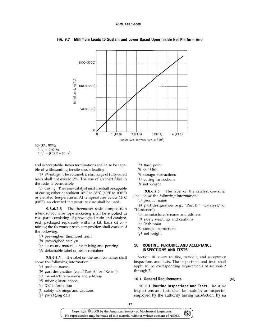
ASME A1S.1-200S
Fig. 9.7 Minimum Loads to Sustain and Lower Based Upon Inside Net Platform Area
/ /
/ /
1500 (3300)
V" / V
g bIl 1000 (2200) ..><:
-r;j ~
.3 ""0
/ V ~
~ 0:::
500 (1100)
/' o /
o 1 (10.8) 2 (21.5) 3 (32.4) 4 (43.1)
Inside Net Platform Area, m2 (ft2)
GENERAL NOTE: 1 lb = 0.45 kg 1 ft2 = 9.29 E - 02 m2
and is acceptable. Resin terminations shall also be capable of withstanding tensile shock loading.
(b) Shrinkage. The volumetric shrinkage of fully cured resin shall not exceed 2%. The use of an inert filler in the resin is permissible.
(c) Curing. The resin-catalyst mixture shall be capable of curing either at ambient 16°C to 38°C (60 0 P to 1000 P) or elevated temperatures. At temperatures below 16°C (600 P), an elevated temperature cure shall be used.
9.8.6.2.3 The thermoset resin composition intended for wire rope socketing shall be supplied in two parts consisting of preweighed resin and catalyst, each packaged separately within a kit. Each kit containing the thermoset resin composition shall consist of the following:
(a) preweighed thermoset resin (b) preweighed catalyst (c) necessary materials for mixing and pouring (d) detachable label on resin container
9.8.6.2.4 The label on the resin container shall show the following information:
(a) product name (b) part designation (e.g., "Part A" or "Resin") (c) manufacturer's name and address (d) mixing instructions (e) ICC information (j) safety warnings and cautions (g) packaging date
57
(h) flash point (i) shelf life (j) storage instructions (k) curing instructions (l) net weight
9.8.6.2.5 The label on the catalyst container shall show the following information:
(a) product name (b) part designation (e.g., "Part B," "Catalyst," or
"Hardener") (c) manufacturer's name and address (d) safety warnings and cautions (e) flash point (j) storage instructions (g) net weight
10 ROUTINE, PERIODIC, AND ACCEPTANCE INSPECTIONS AND TESTS
Section 10 covers routine, periodic, and acceptance inspections and tests. The inspections and tests shall apply to the corresponding requirements of sections 2 through 7.
10.1 General Requirements (08)
10.1.1 Routine Inspections and Tests. Routine inspections and tests shall be made by an inspector employed by the authority having jurisdiction, by an
Copyright © 2008 by the American Society of Mechanical Engineers. No reproduction may be made of this material without written consent of ASME.
ASME A1B.1-200B
inspector employed by an accredited insurance company, which is the primary insurer of the equipment to be inspected, or by a person authorized by the authority having jurisdiction.
10.1.2 Periodic Inspections and Tests
10.1.2.1 Periodic inspections and tests shall be witnessed by an inspector employed by the authority having jurisdiction, except as specified in para. 10.1.2.3.
10.1.2.2 The owner or his authorized agent shall have all of the tests required by para. 10.3 made by a person qualified to perform such service in the presence of an inspector employed by the authority having jurisdiction, except as specified in para. 10.1.2.3.
10.1.2.3 Where the authority having jurisdiction does not employ a qualified inspector, it shall authorize a qualified person to witness the inspection and tests on its behalf. Immediately after the inspection and tests, the inspector shall submit to the authority having jurisdiction a statement certifying that the inspection and tests have been performed and a report on the results thereof.
The authority having jurisdiction may authorize the person witnessing the tests to
(a) submit to the owner or his authorized agent a statement certifying that the tests have been performed and a report on the results thereof
(b) attach a metal tag to the tested devices as required
10.1.3 Acceptance Inspections and Tests
10.1.3.1 The acceptance inspection shall be made by an inspector employed by the authority having jurisdiction, except as specified in para. 10.1.3.3.
10.1.3.2 The person installing or altering the equipment shall perform all of the tests required by para. 10.4 or 10.5 in the presence of an inspector employed by the authority having jurisdiction, except as specified in para. 10.1.3.3.
10.1.3.3 The authority having jurisdiction may authorize a qualified person to make the inspection and witness the tests on its behalf. Immediately after the inspection and tests, the inspector shall submit to the authority having jurisdiction a statement certifying that the inspection and tests have been performed and a report on the results thereof.
10.1.4 Qualification of Inspectors. All inspectors shall meet the qualification requirements of ASME QEI-l. Inspectors and inspection supervisors shall be certified by an organization accredited by ASME in accordance with the requirements of ASME QEI-l.
10.1.5 Applicability of Inspection and Test Requirements. Inspections and tests required by section 10
58
are to determine that the equipment conforms with the following applicable standard requirements:
(a) the standard requirements at the time of installation
(b) the standard requirements at the time of any alteration
10.1.6 Installation Placed Out of Service. When an installation is placed out of service (see para. 1.3, Definitions), inspections and tests may be discontinued. Before the installation is put back in service, it shall be subject to all of the required routine and periodic tests and inspections, including the I-year, 3-year, and 5-year tests.
10.2 Routine Inspections and Tests
10.2.1 Inspection and Test Periods. The routine inspections and tests of sections 2, 3, and 4 lifts shall be made at intervals not longer than 6 months. Routine inspections and tests of sections 5, 6, and 7 lifts shall be made at intervals not longer than 1 year.
10.2.2 Inspection and Test Requirements. Routine inspections and tests shall include where applicable the following:
10.2.2.1 Inside Platform Inspections (a) Stop switches (b) Operating control devices (c) Floor and landing sill (d) Lighting (e) Emergency signal if) Door or gate (g) Enclosure (h) Floor (i) Signs and operating device symbols (j) Rated load, platform floor area, and data plate (k) Ride
10.2.2.2 Machine Inspections (a) Enclosure of machine space (b) Guarding of exposed auxiliary equipment (c) Overhead beam and fastenings (d) Drive machine brake (e) Traction drive machines (f) Gears and bearings (g) Winding drum machine (h) Belt- or chain-drive machine (i) Traction sheaves (j) Secondary and deflector sheaves (k) Rope fastenings (l) Slack rope devices (m) Governor, overspeed switch, and seal (n) Platform safeties (0) Hydraulic power unit (p) Control valves (q) Hydraulic cylinders
Copyright © 2008 by the American Society of Mechanical Engineers. ~ (i S
No reproduction may be made of this material without written consent of ASME. 11'1 e
ASME A1S.1-200S
10.2.2.3 Inside Runway Inspections (a) Platform, overhead, and deflector sheaves (b) Normal terminal stopping devices (C) Final terminal stopping devices (d) Broken rope, chain, or tape switch (e) Counterweight if) Head room (g) Slack rope devices (It) Traveling sheave (i) Platform safeties and guiding members (j) Runway construction (k) Pipes, wiring, and ducts (l) Runway clearances (m) Traveling cables and junction boxes (n) Door and gate equipment (0) Platform frame (p) Guide rails fastening and equipment (q) Governor rope (r) Governor releasing carrier (s) Wire rope fastening and hitch plate (t) Suspension rope (u) Compensation ropes and chains
10.2.2.4 Outside Runway Inspections (a) Runway doors (b) Runway door locking devices (c) Runway enclosure
10.3 Periodic Inspections and Tests
Inspection and Test Periods. In addition to the routine inspections and tests (para. 10.2), the applicable inspections and tests specified in para. 10.3.1 shall be performed in intervals not longer than 1 year, the applicable inspections and tests specified in para. 10.3.2 shall be made at intervals not longer than 3 years, and the applicable inspections and tests specified in para. 10.3.3 shall be made at intervals not longer than 5 years.
10.3.1 One-Year Inspection and Test Requirements
10.3.1.1 Cylinders. Cylinders that are exposed shall be visually inspected. Cylinders that are not exposed shall be tested. After a minimum of 15 min, a change in platform position that cannot be accounted for by visible oil leakage, valve leakage, or temperature change indicates a leak in the unexposed portion of the cylinder or the piping.
10.3.1.2 Safeties
10.3.1.2.1 All working parts of platform safeties shall be inspected to determine that they are in satisfactory operating condition.
10.3.1.2.2 Safeties shall be subjected to the following tests with no load in the platform.
(a) Type A, B, or C governor-operated safeties shall be operated by tripping the governor by hand with the platform operating at the slowest operating speed in the
59
down direction. In this test the safety shall bring the platform to rest promptly. In the case of Type A, B, or C safeties employing rollers or dogs for application of the safety, the rollers or dogs are not required to operate their full travel.
(b) Governor-operated wood guide-rail safeties shall be tested by tripping the governor by hand with the platform at rest and moving the platform in the down direction until it is brought to rest by the safety, and the hoisting ropes slip on the traction machines or become slack on winding drum machines.
(c) Type A and wood guide-rail safeties without governors, which are operated as a result of the breaking or slackening of the hoisting ropes, shall be tested by obtaining the necessary slack rope to cause it to function.
10.3.1.3 Governors. Governors shall be inspected and operated manually to determine that all parts, including those that impart the governor pull-through tension to the governor rope, operate freely.
10.3.1.4 Slack-Rope Devices on Winding Drum Machines. Slack-rope devices on winding drum machines shall be operated manually and inspected to determine conformance with the applicable requirements.
10.3.1.5 Normal and Final Terminal Stopping Devices. Normal and final terminal stopping devices shall be inspected and tested to determine conformance with the applicable requirements.
10.3.1.6 Broken Rope, Tape, or Chain Switch. Where a rope, tape, or chain is used to connect the motion of the platform to the machine room normal limit, the switch that senses failure of this connection shall be tested.
10.3.1. 7 Slack-Rope Device on Roped-Hydraulic Machines. Slack-rope devices for roped-hydraulic lifts will be tested for conformance by lowering the platform or blocking and creating slack rope causing the device to operate. The slack rope can also be obtained by operation of the safety during the annual safety test.
10.3.2 Three-Year Inspection and Test Requirements
10.3.2.1 Unexposed Portions of Pistons. Piston rods of roped water hydraulic lifts shall be exposed, thoroughly cleaned, and inspected for wear or corrosion. The piston rods shall be replaced if at any place the diameter is less than the root diameter of the threads.
10.3.3 Five-Year Inspection and Test Requirements
10.3.3.1 Platform Safeties. Types A, B, and C safeties, except those operating on wood guide rails and their governors, shall be tested with rated load in the platform. Test shall be made by tripping the governor
Copyright © 2008 by the American Society of Mechanical Engineers. No reproduction may be made of this material without \Witten consent of ASME.
ASME A1S.1-200S
by hand at the rated speed. The following operational conditions shall be checked:
(a) Type B safeties shall stop the platform with the rated load within the required range of stopping devices for which the governor is tripped.
(b) For Type A safeties and Type A safety parts of Type C safeties, there shall be sufficient travel of the safety rollers or dogs remaining after the test to bring the platform and its rated load to reston safety application at governor tripping speed. A metal tag shall be attached to the safety-releasing carrier in a permanent manner, giving the date of the safety test together with the name of the person or firm who performed the test.
10.3.3.2 Governors
10.3.3.2.1 The tripping speed of the governor and the speed at which the governor overspeed switch, where provided, operates shall be tested to determine conformance with the applicable requirements and the adjustable means shall be sealed.
10.3.3.2.2 The governor rope pull-through force shall be tested to determine conformance with the applicable requirements, and the adjustment means shall be sealed.
10.3.3.2.3 After these tests, a metal tag indicating the date of the governor tests together with the name of the person or firm that performed the tests shall be attached to the governor in a permanent manner.
10.3.3.3 Brake. The brake shall be tested by placing 125% of rated load in the platform and running it to the lowest landing by normal operating means. The driving machine shall safely lower, stop, and hold the platform with this overload.
10.3.3.4 Ropes. Ropes used on roped-hydraulic lifts shall be inspected. Coated rope shall be required to have a magnetic flux test capable of detecting broken wires in addition to a visual test.
10.3.3.5 Fastenings. Wire rope fastenings on roped-hydraulic lifts utilizing hydraulic jacks equipped with pistons that are hidden by cylinder head seals shall also be inspected even if it is temporarily necessary to support the platform by other means and disassemble the cylinder head.
10.4 Acceptance Inspections and Tests
Inspections and Tests Required. All new installations shall be inspected and tested to determine their safety and compliance with the applicable requirements of this Standard before being placed in service. The inspections and tests shall include routine (para. 10.2), periodic (para. 10.3), and those specified in para. lO.4.L
Installations on which alterations have been performed shall be inspected and tested as required by para. 10.5 before being placed back in service.
60
10.4.1 General Requirements for Types A, B, and C Safeties. The following requirements apply to the acceptance tests of Types A, B, and C safeties.
10.4.1.1 Platform safeties shall be tested with rated load in the platform. In making the test of platform safeties, the load shall be centered on each quarter of the platform floor symmetrically with respect to the center lines of the platform floor. Counterweight safeties, where provided, shall be tested with no load in the platform.
10.4.1.2 The tripping speed of the governor shall be measured by means of a tachometer.
10.4.1.3 If adjustments to the governor tripping speed are made, the governor shall be sealed immediately following the test.
10.4.1.4 The operation of the governor overspeed and the platform safety-mechanism switch shall be tested to determine conformance.
10.4.1.5 After the safety has stopped the plat-form, the level of the platform floor shall be checked to determine conformance.
10.4.2 Type A Governor-Operated Safeties. Type A governor-operated safeties shall be tested by operating the platform at its normal speed in the down direction and tripping the governor jaws by hand. A test shall also be made of the inertia application of the safety to determine conformance by attaching the proper weight to the return run of the governor rope. The manufacturer shall inform the person making the test of the weight necessary to be added to the governor rope when making the inertia application test. This weight shall be the weight necessary to reproduce inertia operation of the safety, at not more than ~o gravity. The inertia application test shall be made with the platform stationary, and the weight when released shall move the safety parts into contact with the rails. Inertia application of the safety on Type A auxiliary safety plank of Type C safeties is not required.
10.4.2.1 If means other than inertia application of the safety is provided, such means shall be tested in an appropriate manner to ensure that the safety will apply without appreciable delay under free-fall condition and that safety application is independent of the location of the break in the hoisting ropes.
10.4.3 Type A Safeties Without Governors. Type A safeties without governors, which are operated only as a result of the breaking or slackening of the suspension ropes, shall be tested by obtaining the necessary slack rope to cause it to function.
10.4.4 Types Band C Safeties
10.4.4.1 Types Band C safeties shall be subjected to an overspeed test, with the suspension ropes attached,
Copyright © 2008 by the American Society of Mechanical Engineers. No reproduction may be made of this material Mthout written consent of ASME.
ASME A1B.1-200B
by gradually increasing the speed of the platform until the governor causes application of the safety. Safeties of lifts equipped with alternating current driving machine motors, where the platform with its rated load does not cause sufficient overspeed when the machine brake is released to trip the governor jaws, shall be tested by operating the platform at its normal speed in the down direction and tripping governor jaws by hand.
10.4.4.2 The overspeed switch on the governor shall be inoperative during the overspeed test. In order to assume that the safety will retard the platform with minimum assistance from the driving machine and minimize the development of slack rope and fallback of the counterweight, the switch on the platform operated by the platform safety mechanism shall, for the duration of the test, be temporarily adjusted to open as close as possible to the position at which the platform safety mechanism is in the fully applied position.
10.4.5 Normal Terminal Stopping Devices
10.4.5.1 The bottom normal terminal stopping device shall be tested with 125% of rated load on the platform for conformance.
61
10.4.5.2 The top normal terminal stopping device shall be tested with no load on the platform for conformance.
10.4.6 Stop Ring. The plunger shall be inspected by inching the platform up to verify that a stop ring has been provided.
10.4.7 Bottom Cylinder Clearance. The bottom cylinder clearance shall be checked to determine conformance.
10.4.8 Speed. The rated speed in the up direction and the operating speed in the down direction shall be verified.
10.5 Inspection and Test Requirements for Altered Installations
Where any alteration is made, the entire installation shall comply with the applicable sections 2 through 7 including para. lOA, Acceptance Inspections and Tests.
Copyright © 2008 by the American Society of Mechanical Engineers. No reproduction may be made of this material without written consent of ASME.
INTENTIONALLY LEFT BLANK
62
Copyright © 2008 by the American Society of Mechanical Engineers. No reproduction may be made of this material without mitten consent of ASME.
ASME Services
ASME is committed to developing and delivering technical information. At ASME's Information Central, we make every effort to answer your questions and expedite your orders. Our representatives are ready to assist you in the following areas:
ASME Press Codes & Standards Credit Card Orders IMechE Publications Meetings & Conferences Member Dues Status
Member Services & Benefits Other ASME Programs Payment Inquiries Professional Development
Short Courses Publications
How can you reach us? It's easier than ever!
Public Information Self-Study Courses Shipping Information Subscriptions/Journals/ Magazines Symposia Volumes Technical Papers
There are four options for making inquiries* or placing orders. Simply mail, phone, fax, or E-mail us and an Information Central representative will handle your request.
Mail ASME 22 Law Drive, Box 2900 Fairfield, New Jersey 07007-2900
Call Toll Free US & Canada: 800-THE-ASME (800-843-2763) Mexico: 95-800-THE-ASME (95-800-843-2763) Universal: 973-882-1167
Fax-24 hours 973-882-1717 973-882-5155
E-Mail-24 hours [email protected]
* Information Central staff are not permitted to answer inquiries about the technical content of this code or standard. Information as to whether or not technical inquiries are issued to this code or standard is shown on the copyright page. All technical inquiries must be submitted in writing to the staff secretary. Additional procedures for inquiries may be listed within.
Copyright © 2008 by the American Society of Mechanical Engineers. ~ No reproduction may be made of this material without written consent of ASME. ~
ISBN-13: 978-0-7918-3145-8
ISBN-10: 0-7918-3145-0
9 780791 831458
1111111111111111111111111111111111111111 ~ ______________________________________________ ~A14508
Copyright © 2008 by the American Society of Mechanical Engineers. ~ No reproduction may be made ofthis material without written consent of ASME. ~