aspects of building geometry and powder characteristics in...
TRANSCRIPT

THESIS FOR THE DEGREE OF LICENTIATE OF ENGINEERING
Aspects of building geometry and powder
characteristics in powder bed fusion
ALEXANDER LEICHT
Department of Industrial and Materials Science
CHALMERS UNIVERSITY OF TECHNOLOGY
Gothenburg, Sweden 2018

Aspects of building geometry and powder characteristics in powder bed fusion
Alexander Leicht
© Alexander Leicht, 2018
Technical report no. IMS-2018-1
Department of Industrial and Materials Science
Chalmers University of Technology
SE-412 96 Gothenburg
Sweden
Telephone + 46 (0)31-772 1000
Printed by Chalmers Reproservice
Gothenburg, Sweden 2018
i
Aspects of building geometry and powder
characteristics in powder bed fusion
Alexander Leicht Department of Industrial and Materials Science
Chalmers University of Technology
Abstract
Additive manufacturing (AM) produces near-net-shaped parts directly from a 3D-CAD model
in a layer-by-layer manner. One of the most common AM technique for fabricating metallic
components is powder bed fusion (PBF). The PBF process has shown great potential in
fabricating metallic parts with properties better or comparable to conventional methods.
However, there are some challenges in reproducibility, process stability, robustness, etc. This
thesis elaborates on several of these challenges and addresses the influences of feedstock
material, build orientation and part design on the final outcome.
The PBF process uses fine metal powder as feedstock material and in order to have an
economically feasible process, powder recycling is a necessity. However, to ensure a robust
process and consistent material properties, the feedstock material need to be handled with
caution as powder properties will affect the part quality. The obtained results for 316L
stainless steel from this study indicate that powder degradation in terms of surface product
changes occurs when the powder is recycled. It was revealed that both recycled and virgin
powder were covered by a heterogeneous oxide layer, composed by a homogeneous iron oxide
layer with the presence of Cr-Mn-rich oxide particulates that were growing during PBF
processing. The results showed that the powder degradation was more pronounced when used
in the electron beam system compared to a laser based system due to the long exposure at
high temperatures.
The manufacturing capabilities of the PBF process has enabled the production of lattice
structures without extensive tooling. The properties of such lattice will be influenced by the
microstructure. Hence, it is of importance to understand how the part geometry would affect
the microstructure. This study presents the effect of build geometry, as e.g. wall thickness
and build angle on the 316L microstructure. The obtained results indicated that in the center
of ribs over 0.6 mm in thickness, large elongated grains with preferential <101> orientation
were created. Reducing the part thickness to below 0.6 mm reduced the predominant texture.
The increased cooling rate close to the part surface inhibited grain growth and changed the
preferential grain orientation. For the process parameters used, the critical part thickness to
avoid large elongated grains was found to be about 0.4 mm. The obtained results could be
used for further development of design rules and prediction of mechanical properties of AM
parts with small wall thicknesses.
Keywords: additive manufacturing, powder bed fusion, powder recycling, stainless steel, thin
wall structures, microstructure, direct metal laser sintering, electron beam melting, 316L

ii

iii
Preface
The work has been carried out in the Department of Industrial and Materials Science,
Chalmers University of Technology (Gothenburg, Sweden) under the supervision of Prof.
Eduard Hryha and Prof. Lars Nyborg. This licentiate thesis comprises an introduction and a
review of some aspects of powder bed fusion of stainless steel.
List of appendant papers
I. Degradation of stainless steel 316LN powder associated with additive
manufacturing by Electron Beam Melting
A. Leicht, R. Shvab, L. Nyborg, E. Hryha
Submitted
II. Surface Oxide State on Metal Powder and its Changes during Additive
Manufacturing: an Overview
E. Hryha, R. Shvab, H. Gruber, A. Leicht, L. Nyborg
Proceeding of Euro PM 2017 Congress & Exhibition, Milan, Italy 2017
III. Effect of build geometry on the microstructural development of 316L parts
produced by additive manufacturing
A. Leicht, U. Klement, E. Hryha
Submitted
Contribution to the appended papers
I. The author planned and performed the experimental work, took part in the
analysis of the results in collaboration with the co-authors as well as wrote the
paper in close cooperation with the co-authors.
II. The author performed the characterization and analysis of the stainless steel
powder as well as participated in the writing of the paper.
III. The author planned and performed the experimental work as well as the analysis
in collaboration with the co-authors. The author wrote the paper in cooperation
with the co-authors.
Paper not appended in this thesis
I. Characterization of virgin and recycled 316L powder used in additive
manufacturing
A. Leicht, R. Shvab, E. Hryha, L. Nyborg, L.-E. Rännar
Conference proceeding of SPS16, Lund, Sweden 2016
II. Characterization Of The Virgin And Re-cycled Nickel Alloy HX Powder Used For
Selective Laser Melting
R. Shvab, A. Leicht, E. Hryha, L. Nyborg
Conference proceeding of World PM 2016, Hamburg, Germany 2016
III. As-HIP Microstructure of EBM Fabricated Shell Components
A. Leicht, M. Vattur Sundaram, E. Hryha, L. Nyborg, M. Ahlfors, L.-E. Rännar,
K. Frisk
Conference proceeding of World PM 2016, Hamburg, Germany 2016

iv

v
Contents Chapter 1 – Introduction ............................................................................................................. 1
1.1 Aim of the thesis ............................................................................................................ 2
Chapter 2 – Metal Additive Manufacturing ............................................................................... 3
2.1 Powder Bed Fusion ............................................................................................................ 3
2.2 Process Cycle ...................................................................................................................... 5
2.2.1 Pre-processing .............................................................................................................. 6
2.2.2 Building ........................................................................................................................ 6
2.2.4 Powder Recycling ......................................................................................................... 7
2.3 Powder for powder bed fusion ............................................................................................ 8
2.3.1 Powder Characteristics ............................................................................................... 8
2.3.2 Powder Recycling ......................................................................................................... 9
2.4 Stainless steel ................................................................................................................... 10
2.5 Microstructure Development ........................................................................................... 11
2.6 Design guidelines and mechanical properties ................................................................ 14
2.6.1 Properties of PBF components .................................................................................. 15
2.6.2 Design limitations ..................................................................................................... 16
Chapter 3 - Experimental Methods .......................................................................................... 19
3.1 Material and sample preparation .................................................................................... 19
3.2 Light Optical Microscopy (LOM) ..................................................................................... 20
3.3 Scanning Electron Microscopy (SEM) ............................................................................. 20
3.3.1 Electron Backscattered Diffraction (EBSD) ............................................................. 21
3.4 X-ray Photoelectron Spectroscopy (XPS) ........................................................................ 21
Chapter 4 - Results and Summary of Appended Papers ......................................................... 23
4.1 Powder degradation ..................................................................................................... 23
4.2 Microstructure ............................................................................................................. 25
Chapter 5 - Summary and Conclusions .................................................................................... 27
Acknowledgements .................................................................................................................... 29
References .................................................................................................................................. 31

vi

1
Chapter 1 – Introduction
Additive manufacturing (AM) is defined by ASTM F2792-12a as “a process of joining
materials to make objects from a 3D model data, usually layer upon layers” [1]. In the late
1980s, the process was used as a tool for making prototypes. At that time the process was
immature and resulted in parts with quality that could satisfy only limited demands on
mechanical properties, still enough for visualization and simple handling. Today AM has
matured and can be used for fabrication of high-end fully functional parts besides its extended
use for prototyping. The term additive manufacturing is very broad and covers a large number
of different processes and materials, from consumer machines for 200€ up to high-end
machines with a price well over million euro. Hence, parts can be made for a wide range of
applications, including metallic materials like stainless steel, Ni-based superalloys, Ti- and
Al-alloys, etc. The society has so far gained various benefits from the additive manufacturing
industry, including customized healthcare products which have improved the wellbeing of the
population, the raw material usage and energy consumption can also be reduced owing to
potentially less scrap and hence more efficient material use, which is expected to contribute
to sustainable development, etc. The AM market is growing fast with different stakeholders
including process equipment manufacturers, software and material suppliers,
subcontractors, etc. New value chains, business opportunities and business models are
created thanks to the additive manufacturing during last two decades.
The AM supports the realization of advanced geometrical designs without extensive tooling
as well as designs that would be impossible to create with conventional methods. The high
degree of design freedom makes it possible to add functions without an increase in production
costs. Hence, AM is said to provide complexity for free. At the same time, the design freedom
means that already at the beginning of the product development stage, considerable reduction
in cost and time can be achieved. These attractive characteristics of AM rely on the improved
quality, which has made it possible to fabricate functional prototypes in early stages. The
consequence is that the design iteration becomes faster and cheaper.
Metal AM has been around since the mid-90s and as for AM of polymers, the product quality
was relatively poor at the beginning, with defects, porosity and lack of fusion commonly
observed. Nevertheless, extensive research and development have resulted in hardware and
process development, resulting in the successful technology establishment and
manufacturing of the components for the number of alloys, including Ti- and Al-alloys, Co-Cr
alloys, Ni-base alloys, tool and stainless steels, etc., that are currently available on the
market. This means that parts with properties comparable or better with those obtained with
conventional methods like casting and/or forging can today be fabricated. However, despite
these efforts, the metal AM process is not yet fully developed into its full potential as
reproducibility, productivity, process stability, robustness, etc., are still limited.

2
One of the most common processes for manufacturing of metallic components through AM
today is the powder bed fusion (PBF) which uses a fine gas-atomized metal powder as a raw
material. The AM-specific demands with respect to size distribution, purity and powder
properties mean that such powder is relativity expensive. This means that recycling of un-
melted powder from the process is of crucial importance. It is well known that the powder
properties affect part quality, e.g. relative density, surface roughness and mechanical
properties. Despite the number of the papers published in the topic of powder recycling, there
is no clear understanding of the powder degradation phenomena. At the same time, little or
no consideration has been dedicated to how the surface chemistry of the powder is influenced
by the process and what is the role of the powder surface chemistry in powder bed fusion.
The PBF process has shown great potential for producing high-quality parts in stainless steel.
The laser-based variant is considered to be well-developed with good buildability and a
greater number of qualified alloys, while also the electron-beam based process of stainless
steel has presented good potential in recent research [2,3]. Nevertheless, no conclusive
research has been reported on how the microstructure of 316L parts are affected by build
geometries in detail even if design freedom is one of the large advantages with AM.
1.1 Aim of the thesis This thesis aims to provide basic knowledge on processing of stainless steel powder utilizing
powder bed fusion in order to ensure a robust production of stainless steel components with
complex geometry. The work is focused on understanding the fundamental link between
feedstock material, AM processes, build geometries and their effect on the part quality. This
will ensure high-quality parts realization with high degree of design freedom.

3
Chapter 2 – Metal Additive Manufacturing
This chapter will introduce the powder bed fusion process. Followed by a general explanation
of the production cycle, the correlation between the process, microstructure and feedstock
materials will be elaborated. This chapter facilitates a better understanding of how high part
quality like density, surface roughness and mechanical properties, can be achieved through
powder bed fusion.
2.1 Powder Bed Fusion The AM technology enables the creation of near-net-shaped parts of almost all sizes and from
all material groups. ISO/ASTM 52900 categorizes additive manufacturing into seven process
categories: binder jetting, directed energy deposition, material extrusion, material jetting,
powder bed fusion, sheet lamination and vat photopolymerization. When it comes to the
metals, binder jetting, directed energy deposition, sheet lamination and powder bed fusion
can be utilized. As mentioned in the introduction, the most common sub-technology for
fabrication of metal parts is the PBF. Fig. 1 illustrates a schematic overview of the two most
common PBF setups with some of the most important system parts. Slight variations between
different machine brands and processes will, of course, be the case.
Figure 1: A schematic overview of an laser beam melting process (left) and electron beam
melting process (right)
A common statement is that by utilizing AM and PBF, complexity can be added for free. This
is especially true when comparing the PBF technology with conventional methods, like
casting, forging, etc., see Fig. 2a. Traditionally the cost is continuously increasing with
increased complexity. However, by means of PBF the part cost is more or less constant

4
regardless of complexity and is determined only by the volume of the part. Still, the PBF
technology has some limitations when compared to other powder metallurgy (PM) processes,
also utilizing powder as the base material, such as hot isostatic pressing (HIP), metal injection
molding (MIM) and classical “press and sinter”; as shown in Fig. 2b and c, PBF means
restrictions in both production volume and part sizes. The production volume is limited by
the relatively small build area/volume and slow building time. As an estimation, a few cm3/h
can be fabricated, which is magnitudes lower than what can be achieved by e.g. “press and
sinter”. The part size is limited by the size of building chamber, usually about 25x25x30 cm,
but also by the part size since large parts will increase the process time significantly. By
employing AM, material is only added where needed which opens up the possibility to create
lightweight structures as e.g. lattice designs, with minimum machining which also causes
high material utilization. Since the design freedom is very high, new functions can be created
which would have been impossible to make with conventional methods as e.g. complex
internal cooling channels. This types of features have been fabricated by PBF for e.g. the
polymer injection moulding industry, where moulds have been fabricated. Due to the unique
design possibilities by AM, the cooling channels were optimized for maximum heat
conduction, which resulted in higher productivity and extended tool life [4,5].
Further challenges with PBF is the limited numbers of materials available. At the current
state of the art, there are only about 12 alloys publically available, that are typically weldable
materials. In most cases, the parts fabricated by PBF will show anisotropy with different
mechanical properties along and across the building direction, even if the mechanical
properties, in general, are comparable with wrought materials and better than casting.
Another challenge is the pre- and post-processing. In post-processing, support structures
needed at overhangs must be removed from the final product. Additionally, surface finishing
and heat treatment may be required.
Figure 2: Illustration comparing AM to other technologies; (a) the correlation between
part complexity and cost for conventional manufacturing and additive manufacturing (b) the production volume and complexity for different PM technologies (c) the possible
production volumes and part sizes for different PM technologies.
The foremost important PBF systems can be divided into two different processes depending
on the heat source: laser beam melting (LBM) and the electron beam melting (EBM). Binder
jetting also belongs to PBF systems but will be overlooked in this thesis. The LBM process
involves the use of a high-quality laser beam, typically from an Nd:YAG source. The beam is
guided by mechanically movable mirrors onto the powder bed as shown in Fig. 3a. The
movement of mirrors has a physical limitation when it comes to the speed that, hence, limits

5
the build speed. The process is performed at slightly elevated temperatures, typically between
60 and 200°C, and the build chamber is filled with an inert gas, commonly argon or nitrogen,
in order to minimize oxidation of both powder and the fabricated part. The LBM process
requires powder in the range from10 to 60 µm, depending on the hardware.
In the EBM process, a high energy electron beam with high melting capacity will be generated
from a hot tungsten filament or a LaB6 filament. As shown in Fig. 3b, the beam is controlled
by electromagnetic lenses which makes the process and scanning of the beam faster and more
accurate than in case of laser-based systems. This increases the productivity as compared to
the LBM systems. However, the use of electrons means that the process must be run in
vacuum and the powder bed needs to be conductive. To increase the conductivity and to avoid
sputter of over-charged metal particles, each powder bed layer is pre-sintered and preheated
to a material specific temperature. The pre-sintering will slightly sinter the powder bed
creating a “cake” of powder, which provides natural support for the build components. This
powder cake needs to be crushed when the build is finalized in order to recycle powder. The
preheating temperature is kept throughout the build forming an in-situ stress relieving that
reduces the thermal stresses significantly. In case of the LBM systems, the thermal stresses
in the part are so high that shape distortion may occur if the stresses are not released before
removal. The EBM process requires somewhat larger metal particles, usually 50-150 µm
compared to the typical range used for LBM (10-60 µm). The main reason is to avoid over-
charging of the powder by the electron beam. The use of coarser powder results in a rougher
surface on the part built with EBM compared with LBM.
Figure 3: A schematic overview of the beam control in (a) LBM and (b) EBM.
2.2 Process Cycle In order to create a robust manufacturing routine, the whole processing chain from raw
material to the final part needs to be controlled. In this section, a general description of the
basic procedures of a PBF process will be presented. The procedures are similar for both the
LBM and EBM technologies, but important differences will be addressed.

6
2.2.1 Pre-processing
Initially, the parts need to be created using a 3D CAD-program, involving that the model is
converted to an STL format. The strength of the STL format is that it was primarily developed
for AM and is a standard in the AM industry [6]. Since all CAD software will represent the
part in different ways, the conversion to SLT creates consistency. The STL format is based on
a triangular representation of the part and for this reason, no exact representation of curved
features, etc., can be presented but by increasing the number of triangles a good
approximation can be accomplished. The STL file is imported to a special software where the
build orientation is defined and support structures are added. The STL is thereafter sliced
into thin cross-sectional layers and together with process parameters and a set of files is
transferred to the PBF machine where the support structures and part are created by
selectively consolidating the powder in a layer-by-layer manner until the part is finalized.
2.2.2 Building
The build initiates by applying a thin powder layer on a build plate with 20-50 µm thickness
for the LBM process and 50-100 µm thickness for the EBM process. The beam will be directed
onto the powder bed and selectively melt the powder by creating a melt pool through the heat
absorption by the powder. The size of the generated melt pool is determined by the size of
focus of the energy source and scanning speed and is typically between 50 and 300 µm, larger
in case of EBM. In case of the EBM process, prior to melting the powder bed is preheated by
means of special fast scanning of the electron beam, while pre-heating in this manner is not
possible for LBM. In either case, for the main building, as the beam moves away from the
melt pool generated, the rapid solidification starts. The cooling and hence solidification are
fast; local cooling rates in PBF in the rage of 105 -107 K/s are expected [7]. The building is
controlled by a set of processing parameters like layer thickness, hatch distance, spot size,
focus, power, scanning strategy, etc. The most common scanning strategies are stripe pattern
or island patterns as shown in Fig. 4. In case of the stripe, the scan direction is rotated 67° in
each layer, see Fig. 5. The different scanning strategies and processing parameters will
strongly influence the final quality, i.e. defect, microstructure, surface roughness and residual
stresses. To ensure that the high-quality parts will be created, optimized process parameters
are necessary. When the melting is completed, the build plate is lowered and the cycle is
repeated until the part is finalized.
Figure 4: Two common scanning strategies used in PBF: (a)
stripe pattern and (b) island pattern.
Figure 5: Rotation of scan
direction.

7
2.2.3 Post-Processing
It has been estimated that up to 70% of the part cost may be assigned to the pre- and post-
processing. Consequently, this is a major concern for the AM industry at the current state-of-
the-art. The post-processing is usually done manually and involves removing the un-melted
powder, detaching the part form the build plate and removal of the support structures.
Depending on application, heat treatments such as tempering, solution annealing, stress
relief and hot isostatic pressing (HIP) may be required, which would increase the total
production costs. Furthermore, the PBF process is associated with rough surfaces which in
many cases requires abrasive finishing like blasting and polishing.
2.2.4 Powder Recycling
PBF is associated with a high material utilization and thereby good economic feasibility for
high price materials. To facilitate this, the un-melted powder after each build needs to be
collected and recycled. The following procedures are performed in a recycling sequence: prior
to the build, the machine is loaded with fresh powder, so-called virgin powder, which will be
used for the first build when the part is finalized. The un-melted powder in the build volume
and in the collector bin is vacuumed and sieved to maintain the original size range. The sieved
powder is mixed with a fraction of virgin powder creating a blend which is used for the next
build. A schematic overview of the sequence can be seen in Fig. 6. The procedure of the powder
recycling is dependent on the material and hardware utilized and is not regulated by any
standards and therefore is based on the “best user experience”. Therefore, very little
information is available on how the recycling should be performed, e.g. how many times the
powder can be recycled and how large fraction of recycled powder that should be mixed with
fresh powder, etc. There is also a difference between the EBM and the LBM processes when
it comes to powder recycling. Since the EBM process involves pre-heating each powder layer,
a sintered cake of powder will be created. This cake will be kept at the pre-heating
temperature through the whole build time which in many cases is several hours. In LBM, the
powder in the bed is only heat affected by the built part and if the build plate preheating
temperature, if applied, which is significantly lower than in EBM. The effect of recycling on
the powder will be elaborated in more detail in section 2.3.2.
Figure 6: Overview of the recycling cycle.

8
2.3 Powder for powder bed fusion Most of the commercially available powder for AM is produced by gas atomization, in which
a high-pressure gas stream breaks the molten metal and produces droplets which solidify into
spherical metal particles in a wide array of sizes. Most of the powder used in AM is produced
by either Electrode Induction melting Gas Atomization (EIGA) or Vacuum Induction Gas
Atomization (VIGA). When manufacturing powder of alloys that are sensitive to oxidation,
like stainless steel, an inert gas is chosen as atomizing medium, usually argon or nitrogen.
The processes are associated with low productivity and high price. However, the produced
powder will have high sphericity with, typically, a clean and smooth surface and a low amount
of satellites, see Fig. 7. These types of powder characteristics are desired when it comes to
producing high-quality parts by PBF [8–12]. The produced powder will have a large size range
(1-150 µm). Therefore, the produced powder is sieved and mixed to create a batch with wanted
powder size distributions (PSD). Hence, the prices will to some extent be determined which
PSD that is used.
Figure 7: SEM image showing gas atomized 316L powder particles produced by VIGA.
2.3.1 Powder Characteristics
From the ASTM F3049-14 the following powder characteristics can be identified: size
distribution, morphology, chemical composition, flowability and apparent density. These
characteristics comprise a mixture of measures based on both theory-based and empirical
methods. Understanding the effect of these characteristics on final built part quality is
fundamental for further development and improvement of the AM technology. The
characteristics are supposed to represent the powder quality and it is expected that the
powder quality may influence several important aspects of the PBF process, including the
achievable mechanical properties, defect formation, reproducibility, build consistency, etc. A
broad explanation of how each of the powder characteristics will affect the process and its
implication on part quality will be described in this section.
An important powder characteristic for the PBF process is flowability (how well a powder
flows). Poor flowability could lead to inhomogeneous spreading and low packing density. The
packing density is a measure of the capacity of powder to gain certain relative density and it
will be affected by the flowability, which in turn is determined by the inter-particle friction.
At low powder bed density, defects like lack of fusion and porosity will be more easily
generated. Therefore, to fabricate defect free parts with good dimensional accuracy, the
powder should have as high flowability as possible [8,13–15]. However, to ensure both high
9
flowability and high packing density, powder PSD needs to be optimized. The PSD should be
intermediate since wide PSD will reduce the flowability whereas a narrow PSD could lead to
insufficient packing density [8,14–16]. The flowability is also affected by the powder
morphology; irregular powder and large amount of satellites will decrease flowability,
whereas small spherical particles with smooth surface promote better flow [13–22]. Moreover,
the powder itself needs to be defect-free since internal porosity increases the risk for defects
like gas porosity and lack of fusion in the final product [20].
Parts produced from powder will be strongly affected by both the surface chemical
composition and the bulk chemical composition of the feedstock. It is therefore essential to
understand how the powder surface chemistry affects the part quality. However, so far little
attention has been dedicated to this topic. Nevertheless, some studies have shown that to
avoid defects, like balling and lack of fusion, good wetting to the underlying substrate is vital.
Surface contamination and/or presence of surface oxides means that the wetting might be
reduced and hence the risk for defects increases [23]. Therefore, the powder should be handled
with care both inside and outside the process. To avoid oxidation of the powder inside the
build chamber, where it is exposed to an elevated temperature, an inert gas or a high vacuum
is needed to protect the powder surface. This is especially important for the materials which
are alloyed with elements sensitive to oxygen, like stainless steel, Ti, and Al-alloys [14,23–
25]. The large surface area of the powder in combination with the presence of elements with
high oxygen affinity, like e.g. Cr, Mn, Si, Ti, Al, etc., can result in significant oxidation of the
powder which could affect the particle bonding to the layer beneath and hence impact the
quality of the part [26]. Finer powder will tend to have higher oxygen content due to the
higher specific surface area compared to that of the coarser powder. The chemical composition
also will influence many material characteristics like melting temperature, mechanical
properties, thermal conductivity, heat capacity, etc.
2.3.2 Powder Recycling
The powder recycling, explained in section 2.2.4, can affect several of the powder
characteristics mentioned before like chemical composition, surface morphology (surface
roughness, particle roundness), physical properties (flowability, PSD, etc.). In this section,
some of the key findings in literature will be discussed in terms of implications for robustness
of the process. Several studies have been conducted on the effect of the powder recycling on
the change in the powder bulk composition, particle size, apparent density, tap density,
particle morphology and particle size distribution, etc. Most of the studies have been directed
on Ti-6Al-4V or Ni-based alloys. Most of the recyclability studies that have been conducted
indicate that the EBM process affects the powder more than expected, due to the pre-sintering
as well as exposure of the powder cake to rather large temperature for long build times [20,27–
30]. However, different alloys will be affected in different ways. For example, Ti-6Al-4V will
create a stable oxide layer as well as dissolve some oxygen in the matrix compared to high-
alloyed steels as e.g. 316L that will create particulates on the surface instead.
When the powder is recycled, slight oxygen pick-up can be expected from atmospheric
exposure, especially during the blasting and sieving steps. Also, the time and temperature
that the powder experience in the AM process might lead to thermally activated oxide growth
on the powder surface and hence powder degradation. If the powder is recycled for number of

10
times (over 30 cycles) morphology change of the powder particles can be expected [10]. A slight
increase in powder agglomeration can be expected, which may results in change in powder
sizes and narrower PSD. In general, for both LBM and EBM, the powder becomes more
irregular and the surface becomes rougher after recycling [30–32]. An unexpected result was
that the slightly better flowability was shown after the recycling, but with some decrease in
the tap density. It was proposed that it is connected to the moisture loss upon AM processing
due to the heat in the process [30]. A drier powder will, in general, have better flowability
[10,33,34]. Still, even if changes in powder characteristics has been shown when comparing
recycled and virgin powder, no significant differences in mechanical properties between parts
built without and with re-cycled powder has been proven [20,30].
To summarize, the flowability seems to be the most important factor that is affecting the AM
product quality. The flowability is expected to be related to resistance in moving between
particles, determined by the surface area, surface roughness and surface chemistry. There
are, of course, many more powder-specific factors that will affect the part quality, but
ensuring high layer density with high evenness is a critical aspect. To achieve this, both the
process and the powder characteristics need to be well understood. From the short review
above, it is clear that recycling process affects the powder properties. Therefore, it is crucial
to further investigate how different AM processes affect the powder and the impact on part
quality. It can also be concluded that more attention to powder recycling is needed when using
the EBM process than when the LBM process is used.
2.4 Stainless steel Stainless steel has been used as an engineering material for decades because of the
combination of good mechanical properties and excellent corrosion resistance. This
combination has made the material suitable for a wide range of applications in several
different sectors such as gas and oil, chemical and petrochemical, marine engineering, food
preparation, pharmaceutical and medical parts.
One of the most common alloys used in PBF is the stainless steel 316L. The alloy is a fully
austenitic material which for the cooling rates of concern does not undergo any phase
transformation upon cooling. The material is also considered to be fairly stable. To stabilize
the austenite and ensure corrosion resistance, both Cr and Ni are added [35]. To ensure that
the steel is stainless, at least 12 wt.% of Cr needs to be contained in the alloy to create the
protective oxide layer that will give both oxidation and corrosion resistance. Nickel needs to
be at a sufficient level so that the austenite phase can be retained up to the melting
temperature. Moreover, low amount of carbon will limit the risk for formation of Cr-rich
carbides. These carbides would reduce the local corrosion resistance drastically and lead to
intergranular corrosions. Also, the cooling rates of concern in PBF (105 -107 K/s) means that
sigma phase formation is not viable. The facts amongst others means that single austenitic
phase structure is expected, which makes the 316L suitable for PBF.

11
2.5 Microstructure Development The properties and quality of a metallic part will, to large extents, be determined by the
microstructure and the amount of defects. The following sections will elaborate on the
development of the microstructure in the component fabricated by means of PBF with the
particular reference to austenitic stainless steel.
The typical PBF microstructure is formed by a complex thermal history with several process
characteristics. Understanding these characteristics is crucial when developing the PBF
process, for new materials or performing process parameters optimization. The thermal
history will depend on the AM process type, metallurgy of material used and process
parameters. Therefore, a diversity of microstructures can be formed [36–38]. Consequently,
it is difficult to make a universal assumption regarding the solidification structure and its
appearance. Nevertheless, some facts can be stated regarding the microstructure. Stainless
steel parts fabricated with PBF will have microstructure characterized by melt pool
boundaries, laser scan tracks and large columnar grains with a fine cellular structure and
precipitates in the cells boundaries.
The melting process initiates when the beam, with a small spot size (100-150 µm), interacts
with the powder bed and by radiation heats the powder well above the melting point, forming
a pool of liquid metal. Both the heating and cooling rates are extremely high owing to the
small interaction volume and solidification starts as soon as the laser beam moves away. To
ensure a fully consolidated part without large defects or lack of fusion, the beam is set to
penetrate 3-5 layers down into the powder bed and therefore fully or partially re-melt the
already solidified layers below. This is schematically shown in Fig. 8. The rapid heating and
cooling followed by the re-melting will generate high internal stresses (by the constraining
surrounding material) and thermally affect diffusional processes like grain growth, phase
transformations and precipitation, resulting in a non-equilibrium microstructure [39–43].
Figure 8: Schematic view of the melt pool and the
partial re-melting which creates a heat flow.

12
This procedure will generate a microstructure consisting of several melt pool boundaries as
seen in Fig. 9. The size of a melt pool is commonly 100-200 μm in width and 25-100 μm in
depth. The depth of the melt pool is an indication of the penetration and re-melting while the
distance from center-to-center is an indication of the hatch distance. Furthermore, as can be
seen in Fig. 10, the microstructure consists of large columnar grains that are aligned in the
building direction. The grains stretch over 100 µm and hence cover several build layers. There
is no tendency for the melt pool boundaries to affect the grain direction. This type of
crystallographic orientated grain structure is commonly associated with AM parts of most
metallic materials [36–38,40,42–48]. The melt will solidify and keep the same
crystallographic orientation as the previous grains as they are nucleated from and grow in
the direction of the maximal thermal gradient in an epitaxial manner [48].
Figure 9: SEM micrograph showing several
melt pool boundaries
Figure 10: EBSD maps showing IPF
coloring in the building direction with high angle grain boundary (black lines)
The development of the microstructure will be determined by the temperature gradient (G)
and the growth rate (R) at the solidification interface (between solid and liquid) [7,39,45]. The
product G R represents to overall cooling rate. The solidification mode may change from
planar to cellular, cellular-dendritic or dendritic depending on the undercooling [7,45] as
schematically shown in Fig. 11. The solidification mode will also be determined by the ratio
between the gradient and the growth rate. High G/R ratio will generate a planar mode while
a low G/R will generate dendritic solidification. The cellular structures observed in PBF
indicate an intermediate G/R. Furthermore, the cooling rate given by the product G R will
control the spacing between the microstructure constituents. Since very high cooling rates
have been reported (105 -107 K/s), fine cellular morphology is formed [7,45]. The growth of the
cellular structure (frequently referred to as sub-cells) is controlled by the advancement of the
solidification front which in turn is controlled by the thermal gradient. Higher heat transfer
results in finer cell structure while the slower dispersion of heat gives coarser cell structure
[7,39,45].

13
Figure 11: Schematic overview of the effect of temperature gradient and growth rate on
the different solidification modes
This fine cellular structure can be observed at higher magnification as shown in Fig. 12. The
size of the cells is generally of between 0.5-1.0 µm in diameter and length reaching 10 to 100
µm. The cells are elongated and can have different growth directions as can be seen by
comparing Fig. 12a and b. The observed alteration in growth direction may originate from a
local change in temperature gradient inside the melt pool [43,45,48,49]. Comparing with
microstructures produced by manufacturing techniques that traditionally have been
considered to include fast cooling such as welding, the microstructure obtained in PBF is
much finer and unique in comparison with microstructures obtained by other metal forming
processes [37,48]. By changing the processing parameters as e.g. energy density, alteration of
cell/dendrites sizes can be achieved owing to the different thermal history. By using higher
energy density, higher thermal input leads to coarsening of the cells [7].
Figure 12: SEM micrograph showing a fine sub-cell structure in two different orientations
(a) perpendicular to the building direction and (b) parallel to the building direction.
The cells are separated by the cell boundaries. In case of Fig. 12 they are not visible as this
sample has been electro-chemically etched in oxalic acid which will preferentially attack the
cellular boundaries. Studies by Z. Sun et al. and Y. Zhong et al. have shown that cell

14
boundaries have higher Mo content and higher dislocations density [37,43]. Hence, an
intergranular cellular segregation network is formed [43]. Similar segregation has been
reported for casting of 316L, the difference is that the cooling rates are much higher in PBF
which will result in finer microstructures. It is reasonable to assume that the high dislocation
density is generated by the rapid cooling associated with the process. It has also been reported
that nano-sized inclusions, rich in Si, are found close to the cell boundaries. Hence, by having
a high amount of oxygen in the build chamber, more inclusions could be formed. Such
inclusions could potentially increase the mechanical properties by hindering dislocation
movement [37,43,49,50].
Initial studies have been done to fabricate 316L by means of EBM [3,51]. In general, high
density was achieved (99.8%), but a few large pores were observed which was believed to be
the result of non-optimal process parameters, as e.g. to thick powder layers [3]. The
microstructure is similar to what has been observed for LBM samples, but with different
characteristics regarding the cell structure. By means of energy-dispersive X-ray spectroscopy
(EDX) analyses, precipitates containing more Cr and Mo were found at the grain boundaries
which were not as easily observed in LBM samples. However, no sigma or laves phase was
found. This might be caused by the fact that the part is kept at elevated temperature during
the whole built by the electron beam pre-heating approach and possibly cooling conditions
associated with the EBM process. It was argued that the precipitates might increase material
brittleness and hence decrease mechanical properties. The geometry of the cell boundaries
had a more irregular shape compared to what has been observed in the LBM samples. Again,
the elevated temperature maintained for long time in EBM was believed to be the cause for
theses differences. The reason was supposed to be that the elevated temperature allows for
more diffusion of any segregated elements from the sub-cell boundaries. Still, even if the EBM
samples can be close to an annealed state, the microstructure was different from what has
been observed from conventional 316L samples.
To summarize, parts fabricated with PBF will consist of anisotropic microstructure with large
elongated grains oriented in the building direction. In some cases, these have preferential
crystallographic orientation. Inside these large grains, a fine cell structure is created [45]. It
is believed that the small size of the cells is a main reason for the improved mechanical
properties for LBM-processed 316L compared to those for conventional wrought or cast 316L
parts [38,52]. The fineness of the cell structure is supposed to be dependent on the cooling
rate experienced in the PBF process.
2.6 Design guidelines and mechanical properties The part quality depends on the mechanical properties which are profoundly determined by
the microstructure and the amount of defects and in turn depend on the process parameters.
Additionally, the part quality will be determined by design aspects affecting the thermal
gradient in the parts such as build orientation, wall thickness, support structures, overhangs,
etc. In this section, some of the key mechanical properties will be elaborated together with
the design advantages and limitations of the PBF process.

15
2.6.1 Properties of PBF components
It is well established that even if PBF parts are characterized by an anisotropy in
microstructure and hence properties, the yield strength for the weakest direction has been
demonstrated to be comparable to that obtained with conventional methods like forging or
casting, in case of well-established PBF process. In PBF of stainless steels, the lowest strength
and ductility are achieved in a vertically built tensile specimen, see Fig. 13. Despite of the
comparably high strength, there are still some challenge with the elongation to fracture
shown to be inferior in AM parts compared to that of its wrought counterparts
[7,38,42,48,49,53,54]. As mentioned in section 2.5, the microstructure consists of large
elongated grains with a fine cell structure inside. As long as the density is high (over 98%)
the main features that will contribute to the tensile strength are the three kinds of
boundaries: melt pool boundaries, grain boundaries and the cell boundaries. It is assumed
that the cell boundaries are the most significant characteristic governing the properties. The
cells are supposed to accumulate dislocations at the boundaries and hence this is expected to
generate a positive effect on the tensile strength [7,38,43,55]. Of course, weak cohesion
between powder layers could occur even with a high density, which would have a negative
impact on the properties.
Figure 13: Tensile properties in different build orientations [56]
The most common defects created in PBF parts are pores obtained during the PBF process as
well as pores arising because of gas entrapped inside the powder during the powder
fabrication. Defects are undesired due to their tendency to weaken the materials and generate
spread in the mechanical properties like e.g. ductility [43,48]. Pores in PBF are typically filled
with argon that cannot be dissolved in the metal and hence the gas will remain as porosity.
Consequently, pores filled with argon cannot be healed by subsequent hot isostatic pressing.
Other defects that could be found in PBF parts are lack of fusion, cracks and un-melted
particles. The defects are commonly created in the interface between layers. Hence, by having
high number of layers would increase the risk for defects [7,35,57]. Therefore, by having a
part oriented normal to the building direction compared to a parallel one, as seen in Fig. 14,
improved final part properties can be gained. Furthermore, since the grains are elongated in
the building direction, having the part orientation normal to the building direction may
minimize microstructure anisotropy and improve the mechanical properties further.
The surface roughness will affect both the mechanical properties (especially fatigue
properties) and the appearance of the manufactured part. A poor surface quality will need to
16
be post-processed and complex shaped parts might need to be manually treated. Hence, to
ensure a good yield from the PBF, the required surface quality needs to be considered. The
surface quality will be determined by the powder size, layer thickness, processing parameters
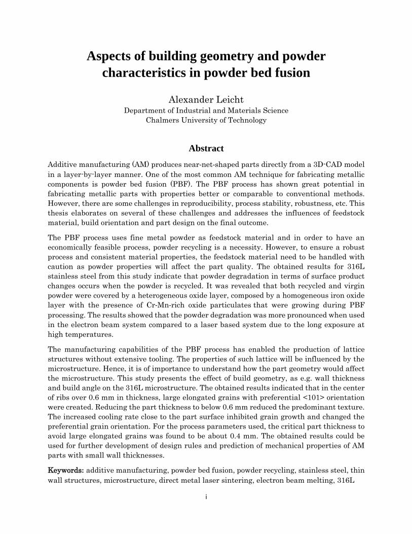
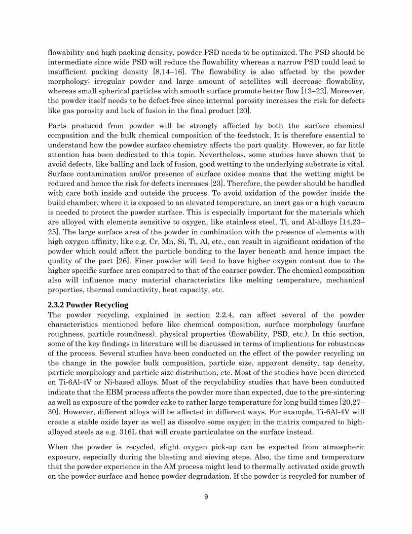
as well as the orientation of the build surface in the build chamber. The surface will have
some slightly sintered metal particles, as can be seen in Fig. 15. Thus, the metal particle size
will affect the surface roughness [58]. Parts produced by means of EBM will generate poorer
surface finish compared with LBM, the reasons being the use of larger powder in the former
case and, in general, the thicker layers. The layer thickness affects both the production rate
and the surface finish. Hence, increasing the production rate decreases the surface finish [59].
Furthermore, it has been shown that by the re-melting and applying contour scanning, the
surfaces can be improved. However, this will also result in lower productivity [41,60]. Other
processing parameters that will affect the surface roughness are hatch distance, power and
scan speed as well as material properties [61]. To improve the surface finish, post-processing
is applied. Amongst others, methods applied include electropolishing, sand blasting, grinding,
etc. However, the surfaces need to be accessible to make it possible to be processed. Hence,
finer internal structures as e.g. small internal cooling channels, are problematic to treat with
traditional post-processing, bringing some limitation to the design freedom.
Figure 14: Part orientation effect on the number
of layers.
Figure 15: Sintered metal particle on
the surface of a PBF part [62].
2.6.2 Design limitations
In this section, some of the design guidelines associated with PBF will be elaborated and
connected to the quality attributes such as surface roughness, mechanical properties, density,
residual stresses and dimensional accuracy. In order to generate good quality and a feasible
economy, demands are put on proper design for AM and especially its connection to the post-
processing, depending on the requirements on the component and its surfaces characteristics.
It could be argued that robustness of the PBF process is limited by part accuracy, surface
finish, repeatability and the restrictions in material selection. Elaborating and highlighting
these limitations could further strengthen the application of the PBF process. Therefore,
establishing sets of design guidelines could improve the use of PBF and result in further
improved products. However, the design guidelines must also emphasize the limitations of
the PBF process, rather than provide design features as e.g. maximum build angles, minimum
wall thicknesses, etc. Addressing how these limitations affects the part quality, can then
increase the robustness of the PBF process by allowing design choices based on function,
appearance and quality. It is also important to mention that the current design limitations
are hardware-dependent and they are also continuously altered and processing technology is
developed and hence has to be periodically reconsidered.

17
First of all, in order to achieve repeatability for fabricated parts, good control of the process
and the process parameters are a must. Hence, well-established process parameters are
required as well as a well-controlled feedstock material. Failure to properly design
components for AM will bring significant risk of either underperforming components or
decreased economic feasibility/increased component price. Furthermore, the improper design
(improper component orientation or support structures, etc.) significantly increase the risk of
the build failure due to the limitations of the hardware. However, as mentioned before, adding
complexity is a superior way for increasing value of the AM process. Therefore, an overview
of some of the geometrical elements that need to be addressed for a successful and high
accuracy build will be discussed. However, there might be constraints that differ between
processes and hardware as the powder spreading (different blade materials as HLS-steel,
ceramic, carbon brush, rubber rake, etc.), scanning strategy, etc. These differences will
generate different constraints. Nevertheless, some general rules can be provided.
An important design feature for the PBF process is the possibility to make struts and lattice
structures which can be used for fabricating light-weight components. A number of generic
design criteria has been developed as follows. By making the wall and struts as thin as
possible, the weight of the component can be reduced. The struts can be made down to a
diameter of 0.15 mm while walls have a minimum thickness of around 0.2 mm [63]. However,
a thin wall might not be self-supported meaning that when the rake spreads the powder
failure might occur. Furthermore, most processes have a limitation in the length-to-height
ratio which in most cases needs to be below 8:1. The designs are, of course, not always
straightforward meaning that the part will be built at an angle. This will create an overhang
with a top surface and a bottom surface, commonly known as top-skin and bottom-skin. The
recommendation is that build angles lower than 45° should be supported from below. It has
been shown that by decreasing the build angle the staircase effect increases and also the
surface roughness [64]. Since the process is done in a layer-by-layer manner, a layer thickness
will generate a stair height and the staircase effect is the approximation of a single layer
compared to the CAD model, see Fig. 16.
Figure 16: The staircase effect created by the PBF process due to the
layer-by-layer processing
Another potential application is the fabrication of tools with internal cooling channels which
has shown to be a promising business case. To fabricate these channels, holes of different
diameters are needed with a recommended minimum diameter of 0.4 mm. The main problem
with these small holes is the powder removal, especially if the cooling channels have a

18
complex pass. The beam intensity has to be carefully adjusted to avoid too deep penetration
into the powder bed and hence risking that the walls of the fine channels are fused together.
In the upper range, holes over 10 mm in diameter will need support structures. These
supports needs to be removed which could be difficult in e.g. internal cooling channels.
However, by a proper design, the need for support structures might be eliminated; for
example, by making the channels like keyholes or more oval in cross-section. Furthermore, in
general, when making channels, subsequent surface treatment will be challenging since the
channel is more or less impossible to access with any tools. There are some methods that
involve etching with fluids or utilization of the abrasive liquids at elevated pressures, etc.
However, these are in many cases both expensive and time consuming.
The support structures have several functions including supporting of overhangs, conduction
of heat, prevention of warping, etc. At the same time, the support structures should also be
easy to remove and should be minimized in number and complexity. By proper part design
and orientation on the building plattform, the amount of the support can be reduced or placed
so that their removal becomes easy. The build surface supported will almost always need
some kind of post-AM finishing. The part orientation will influence both quantities of support
and the build time. Optimizing the built orientation could reduce the build time by e.g.
lowering the part height and hence reducing the number of layers that need to be spread,
which would reduce the cost significantly.

19
Chapter 3 - Experimental Methods
3.1 Material and sample preparation In this work, sample fabricated from two different additive manufacturing processes (LBM
and EBM) have been used for investigation. Both processes utilized a gas atomized stainless
steel powder as feedstock, with specific grade and particle size distribution (PSD) for each
process. The LBM process utilized a 316L powder grade with a PSD of 25-53µm, whereas the
EBM process used 316LN powder grade with a PSD of 53-150 µm. The measured chemical
composition of each powder can be seen in Table 1. The 316L grade has a lower amount of
carbon as compared to the normal 316 grade while the 316LN grade combines lower carbon
content with higher nitrogen content to increase the high-temperature resistance.
The paper I and II covers the powder characterization with focus on recyclability and
degradation of the powders materials. The powder in paper I was processed in the Arcam A2
EBM machine at Mid Sweden University, Sweden, while the powder in paper II was processed
in the EOS M290 machine at Chalmers University of Technology. In paper III,
characterization of 316L parts produced with the EOS M290 process is presented. All the
parts and powder grades investigated have been processed with the standard process
parameters provided by the machine manufactures and the solid parts were investigated in
as-built condition.
Table 1: Chemical Composition of the powder grades used
Elements 316L [wt.%] 316LN [wt.%]
Fe Bal. Bal.
C 0.00939 0.0183
Cr 17,4 17.6
Mn 1.6 1.7
Mo 2.7 2.5
N 0.0568 0.0948
Ni 13.4 12.4
O 0.0436 0.014
P 0.006 0.008
S 0.00526 0.0061
Si 0.3 0.47
All the solid samples, characterized in this study were prepared using standard
metallographic procedure including cutting, grinding and polishing. The samples were
sectioned either along the build direction creating a cross-section in Z-plane or cut
perpendicular to the build direction creating a cross-section in the XY-plane, see Fig. 17. The
Z-direction corresponds to the building direction. The cross-section samples were mounted in
conductive resin and subsequently grinded and polished according to Struers standard

20
procedures for preparing stainless steel. The samples used for microstructure investigations
were polished with 0.04 µm standard colloidal silica suspension (OP-S) and electrochemically
etched in a 20 vol. % oxalic acid with a platinum electrode as counter cathode applying a
potential of 3 V for 10 seconds.
Figure 17: Planar cross-section of the
prepared samples, z-plane (left) and XY-plane
(right)
The powder cross-sections were studied on samples prepared by blending the powder together
with the conductive resin which then was processed into metallographic samples according to
Struers standard preparation routine. The samples were grounded and polished as the solid
samples. The powder cross-sections were etched using Marble’s Reagent (10g CuSO4, 50ml
HCl and 50ml H2O) to reveal the microstructural features. The powder samples for the
SEM+EDX analysis were prepared by slightly pressing the powder onto a soft aluminum plate
which then was mounted on a fixture in SEM instrument. The powder used for surface
chemical analysis by XPS was mounted using carbon tape.
3.2 Light Optical Microscopy (LOM) Light Optical Microscopy (LOM) collects reflected light through a set of lenses and generates
an image of the investigated surface. In this study, a Leitz DMRX microscope was used with
the AxioVison software for microstructural investigation and for porosity analysis in
combination with the image analysis. The porosity investigation was performed on the
polished samples and analyzed by a thresholding procedure using ImageJ, an image
processing software.
3.3 Scanning Electron Microscopy (SEM) Scanning electron microscopy (SEM) provides information about microstructural features and
surface topography at high magnification with high spatial resolution. By directing the
scanning electron beam through the electromagnetic lenses onto a sample surface, different
types of radiations are generated as secondary electrons (SE), backscatter electrons (BSE)
and X-rays, see Fig. 18. The radiations emitted at different depths of the surface will provide
information about the surface characteristics and chemical composition, see Fig. 18b. In this
study, microstructural features and surface topography of the powder and solid samples were
investigated using SE imaging. Additionally, chemical analysis was performed using energy-
dispersive X-ray spectroscopy (EDX), see Fig. 18b and c. However, due to the high interaction
volume, only qualitative and semi-qualitative results were obtained regarding the chemical

21
composition since it was mainly used for examining small (less than 0.5 µm) particulates on
the powder surfaces. The work presented in this thesis has been performed using a LEO
Gemini 1550 (LEO GmbH, Oberkochen, Germany) scanning electron microscope equipped
with an energy dispersive X-ray analyzer, X-Max (Oxford Instruments Ltd., HighWycombe,
UK).
Figure 18: Schematic overview of a scanning electron microscope; (a) working principle, (b)
interaction volume and (c) emission of X-rays
3.3.1 Electron Backscattered Diffraction (EBSD)
In paper III, crystallographic information was obtained by means of electron backscatter
diffraction (EBSD). The generation of backscattered electrons was explained in section 3.3.
By introducing a detector with a fluorescent screen, a diffraction pattern can be obtained and
recorded. The recorded BSE produces a pattern known as Kikuchi bands. By analyzing the
Kikuchi bands, a distinctive pattern can be identified that can give information about the
orientation and crystal structures, the presence of local texturing, grains (orientation,
boundaries and sizes) and phase composition, etc.
The EBSD can either be done as spot analysis or map analysis. To generate a map, the EBSD
is measuring a point for a specific amount of time to gather the pattern and then moving one
step size and making the next measurement, creating a raster grid of points which will
produce an image with crystallographic orientations assigned to specific colors in the
reconstructed image. Hence, smaller step sizes will generate a higher spatial resolution. By
software processing, the results can be presented as inverse pole figures, where specific colors
belong to a crystallographic grain of the same orientation or more specifically to the same
lattice plane but since each plane can be rotated relative to one another, several planes can
generate the same orientation.
The EBSD investigation presented in this thesis was performed with a Nordlys II detector
(Oxford Instruments). An acceleration voltage of 20 keV was applied at a working distance of
10-20 mm with a step size between 0.05-3.0 µm. The EBSD maps were acquired and processed
with Channel 5 software. Grain boundaries were defined to have a crystallographic
misorientation of >10°. All measurements were conducted on polished and etched samples.
3.4 X-ray Photoelectron Spectroscopy (XPS) X-ray photoelectron spectroscopy (XPS) can be used for generating qualitative and
quantitative information about the surface chemical state and composition. XPS is also known

22
as electron spectroscopy for chemical analysis (ESCA). A schematic overview is shown of the
XPS method in Fig. 19. The XPS is a surface sensitive technique that measures the intensity
of the emitted photoelectrons based on their binding energy and is able to detect almost all
the elements, including light elements as e.g. O, C, N, etc. The most important characteristics
of the XPS are high sensitivity, small analysis depth and the possibility to distinguish the
chemical state of the elements. The photoelectrons are created by irradiating the sample with
X-rays that penetrate the surface and interact with the atoms and generate photoelectrons.
To enable a sufficient mean free path of the electrons after exiting the sample and to ensure
that there is no contamination on the surface, the analysis needs to be performed in ultra-
high vacuum. The X-ray photons are produced with a specific energy by using normally either
Mg Kα or Al Kα sources. The energy of the emitted photoelectron is measured with a
spectrometer and the intensity is measured in a specific energy channel. Elements are
identified based on the unique binding energies for different photoelectron for given elements.
The results are plotted with the number of emitted electrons per second against the binding
energy (eV). Since the mean free path of a photoelectron is very small within the analyzed
material, the detected photoelectrons will be generated from the outmost surface typically
from 1-5 nm. A survey spectrum is used for general chemical composition analysis, which is
based on a broad binding energy settings, while high energy resolution narrow scan
measurements are used for determination of the chemical state, i.e. if an element is in the
oxide or metallic state. The XPS analysis is usually first conducted on the as-received surface
and by means alternating Ar+ ion etching and analysis compositional depth profiling can be
achieved.
Figure 19: Schematic overview of the working principle of the XPS method.
In this study, the surface chemical composition of powder studied was analyzed using a PHI
5500 Spectrometer instrument equipped with monochromatic Al Kα (1486.6 eV) X-ray source
for photoelectron generation. The powder was mounted on a carbon tape for the analysis and
the analyzed area was around 0.8 mm in diameter, based on the chosen aperture size. The
acquisition conditions for high-energy spectra were 23.5 eV pass energy with the step of 0.1
eV and a nominal take-off angle of 45°. Curve fitting of the recorded photoelectron peaks was
done utilizing the PHI Multipak software with asymmetric curves and assuming Shirley
background [65]. Compositional depth profiling was done by alternating argon ion etching
with an accelerating voltage of 4 kV, with an angle of 50° between the incident ion beam and
the sample surface. The Ar+ ions were rastered over an area of 4×5 mm2 giving an etching
rate of 3 nm min−1. The etch rate was calibrated on a flat oxidized tantalum foil of 100 nm
thickness. Hence the oxide thickness refers to Ta2O5 units.

23
Chapter 4 - Results and Summary of
Appended Papers
The results presented are based on the summary of the three appended papers. The paper I
and Paper II are focused on the degradation of stainless steel powder associated with the PBF
process. Characterization of both virgin and the recycled powder was conducted in order to
establish an understanding of how the powder is affected by the PBF process. Paper III
emphasizes the effect of the part geometry on the development of microstructure.
4.1 Powder degradation Both kinds of virgin 316L powder showed a clear dendritic solidification structure, observed
both on the particle surface and on the powder cross-section, see Fig. 20. The results from the
powder recycling in the EBM process indicates that the homogenization takes place as a result
of long-term exposure at high temperatures. The extent to which the homogenization
happened depends on the location in the powder bed, as the time and temperature profile are
different at different build height. Homogenization was not observed for powder recycled from
the LBM. Since there is no preheating of the powder bed in the LBM process, the thermal
history for the powder will depend on the distance from the built part and the built plate hold
temperature, which is significantly lower than the temperatures used in EBM.
Figure 20: Microstructure of virgin powder showing a dendritic structure on the (a)
surface and (b) cross-section of the powder.
Both kinds of powder studied are produced by well-controlled gas atomization processes and
are of high quality, exhibiting smooth and clean surface with low amount of satellites. Still,
at higher magnifications evenly distributed fine particulates were observed on the surface of
the virgin powder as shown in Fig. 21a and b. The changes in the powder surface chemistry
and morphology were clearly observed for the recycled powder when it comes to the
morphology, size and amount of these particulates. Clear differences in powder degradation
after EBM and LBM processing were observed as well, see Fig. 21c and d. The particulates
on the powder surface in case of the LBM processed powder are darker and more spherical in
shape and with size of up to 200 nm. The SEM+EDX analyses confirmed that they are rich in
Cr, Mn, Si and Al combined with O. Meanwhile, the virgin powder used for EBM showed

24
particulates enriched in Si, Mn and Cr combined with O. Their size was estimated to be less
than 50 nm. During the EBM process, the oxides grow in size up to ~150 nm while the surface
of the powder used in LBM process appeared to be much less affected.
Figure 21: The particulate features on the powder surface from (a) virgin 316LN (EBM),
(b) virgin 316L (LBM), (c) recycled 316LN (EBM) and (d) recycled 316L (LBM).
The surface chemical composition was measured on the EBM-processed powder by means of
XPS depth profiling. The chemical composition of the outermost surface and down to 50 nm
was measured. A steep decrease in oxygen was observed with increased Fe content for etch
depth down to about 7.5 nm. As shown in Fig. 22, the surface enrichment in Cr and Mn (in
oxide state) in combination with high residual oxygen content at larger etch depths confirm
the presence of particulate oxides features observed by SEM. The main difference is that the
recycled powder had a lower amount of Mn, which is supposed to be connected to the
sublimation of Mn at high temperature during EBM processing (and hence reduction of Mn-
oxide). The results show that the surface of the powder undergoes changes in terms of
chemical composition with a decrease in oxide layer thickness and an increased amount of Cr-
Mn rich oxides particulates.
Figure 22: Relative cation concentration of the surface of (a) the virgin powder and (b) the
recycled 316LN powder used in EBM

25
4.2 Microstructure In order to investigate how part design affects the microstructure, samples with different rib
thicknesses and build inclination were fabricated. The results revealed that by appropriate
design, ribs with 0.2 mm thickness could be successfully fabricated without failure. Moreover,
it was shown that ribs with a build angle of 30° were successfully built without support
structures. However, with inferior surface roughness and poor dimensional accuracy.
The produced samples were investigated in an as-built condition and the cross-section showed
a complex solidification structure, as shown in Fig. 23. This type of solidification structures
is commonly observed in stainless steel part fabricated by PBF as described in section 2.5. As
shown in Fig. 23, the melt pool boundaries are clearly distinguished and are around 100-200
µm in a width and 25-100 µm in depth. The depth of the melt pool is larger than the layer
thickness, meaning that the laser has thermally affected more than one layer and therefore
re-melting of previous layers has occurred. This ensures that the parts were fully consolidated
without large defects and/or lack of fusion regions. Analysis of un-etched samples indicated
that almost full density (over 99.9 %) was achieved independent on rib thickness or build
inclination. Hence no correlation between rib thickness and porosity was observed.
Figure 23: SEM image of the cross-section of the as-built AM parts at (a) low
magnification and (b) higher magnification.
The microstructure of the ribs was investigated by EBSD in order to provide information
about the grain morphology and texture in the components. The EBSD orientation maps
indicated that the microstructure consists of large elongated grains which covers several built
layers and melt pool boundaries as shown in Fig. 24a. The grains were growing in an epitaxial
manner following the building direction with a preferential <101> orientation. Furthermore,
close to the part surface smaller grains were observed. The small grains had grown inwards,
towards the rib center, following the maximum temperature gradient. This tendency was
observed to ~150 µm from the part surface after which large elongated grains were shaped.
For the thinnest ribs (0.2 and 0.4 mm) these small inclined grains were covering the full
thickness as shown in Fig. 24b. The small grains were randomly oriented in contrast to the
large elongated grains. The small grains were assumed to be formed due to an increased
cooling rate closer to the part surface. The increased cooling rate is supposed to hinder grain
growth and change the preferential grain orientation. Furthermore, the ribs which were
fabricated with a build angle indicated that the grains are still elongated in the building
direction rather than being affected by the part geometry, as shown in see Fig. 25. The
inclined ribs had a random texture in contrast to the straight ribs which had a predominant

26
<101> orientation. Close to the surface of the inclined samples small grains were observed,
similar to what was observed in the straight ribs. However, the grains are instead directed in
the same direction as the part.
Figure 24: EBSD orientation maps with inverse pole figure coloring of (a) 1
mm rib and (b) 0.2 mm rib. Provided are also the inverse pole figure color code and the inverse pole figures in (transverse direction (TD), building
direction (BD), and normal direction (ND)).
Figure 25: EBSD orientation maps of different build inclinations (a) 45° and (b) 30°.

27
Chapter 5 - Summary and Conclusions The aim of this licentiate thesis study was to provide improved understanding how to ensure
a robust production of stainless steel when utilizing PBF and to recognize the link between
feedstock materials, build geometry, process and part quality. The results relate to several
aspects that are supposed to influence the final outcome, including pre- and post-processing,
quality of feedstock material, build orientation and part design.
To have an economically feasible PBF process, powder recycling is a necessity. However, to
ensure a robust process and consistent material properties, the feedstock material needs to
be handled with caution. Improper powder handling is expected to affect the part quality
owing to changes in powder characteristics like size distribution, morphology, flowability and
chemical composition. This study has proven the degradation of 316L stainless steel powder
in terms of surface chemistry changes in case of recycled powder. It was revealed that both
recycled and virgin powders were covered by a heterogeneous oxide layer, composed of
homogeneous iron oxide layer with the presence of Cr-Mn-rich oxide particulates. These
particulates were growing during PBF processing, but were most pronounced in the EBM
process. However, the effect of the powder degradation on the component properties is still
not clear and should be further investigated to ensure that proper powder handling can be
further established. Furthermore, the powder degradation was shown to depend on the PBF
process employed, where the EBM process affected the powder more strongly, compared to
LBM, due to the longer exposure at high temperatures.
The PBF process offers almost unlimited design freedom but utilization of its full potential
requires knowledge of how different designs affects the microstructure. In this study, ribs of
different thicknesses and build angles were fabricated in order to understand how the
microstructure is affected by some basic geometrical features. The PBF process produces a
complex microstructure with large elongated grains oriented in the building direction. The
results of this investigation show that close to the part surface (~150 µm) smaller grains are
formed. These grains are inclined towards the center of the part and have random orientation
in contrast to the large elongated grains in the center of the part, which has a preferential
<101> orientation. Hence, the results indicate that wall thickness smaller than 0.6 mm will
have a microstructure consisting of only the small more equiaxed grains with random
orientation. Above 0.6 mm wall thickness, a core of large elongated grains will start to form
in the center of the part. Furthermore, by decreasing the building angle to 45° and 30° for 1
mm thick ribs resulted in grains with a random orientation. However, the microstructure still
contained large elongated grains that followed the building direction, as in the straight ribs.
Hence, the grain growth direction was not affected by the build angle.
In conclusion, to ensure high-quality components manufactured by powder bed fusion, the
whole process needs to be well-controlled. To ensure good reproducibility, more extensive
recycling studies need to be conducted in combination with mechanical testing. Furthermore,
it is reasonable to assume that mechanical properties will change by reducing the wall
thickness owing to the changes in grain size and texture. Therefore, dedicated mechanical
testing will be needed to further understand the impact of thin walled structures and build
orientation.

28

29
Acknowledgements
First I would like to thank my supervisor Prof. Eduard Hryha for giving me the opportunity
to work with this growing and exciting topic and for his guidance. Further, my co-supervisor
Lars Nyborg is greatly acknowledged for his input, guidance and help throughout the work.
I would like to express my gratitude to Prof. Uta Klement for her support and feedback.
I also would like to acknowledge the research engineers Dr. Ruslan Shvab, Dr. Eric Tam, Dr.
Yiming Yao, Dr. Yu Cao, Lic. Eng. Lars Hammar and Roger Sagdahl for their help regarding
all practical work.
Lars-Erik Rännar and Andrey Koptyug from Mid Sweden University are acknowledged their
help with the EBM processing and powder sampling used in this work.
Financial support from Vinnova within the framework of the Metallic Materials programme,
AoA Production at Chalmers, Fusion for Energy through the grant GRT-645,
Västragötalandsregionen and Tillväxtverket is gratefully acknowledged. The results and
conclusions in this thesis report are provided by the author and Fusion for Energy is not held
responsible for any of these results or conclusions.
Recognitions to all the colleagues at the Department of Industrial and Materials Science for
making the time enjoyable.
I would like to thank Camille, Dmitri, Eric, Hans, Johan, Maheswaran, Mikael and Swathi
for all the discussion, ideas, and memorable stories created during our conferences.
I would like to thank my family and friends for reminding me of the world outside the office.
Finally, thanks to Linn and Edvin for their boundless love and support throughout this
journey.

30

31
References
[1] ASTM International, F2792-12a - Standard Terminology for Additive Manufacturing
Technologies, Rapid Manuf. Assoc. (2013) 10–12. doi:10.1520/F2792-12A.2.
[2] L.-E. Rännar, A. Koptyug, J. Olsén, K. Saeidi, Z. Shen, Hierarchical structures of
stainless steel 316L manufactured by Electron Beam Melting, Addit. Manuf. (2017).
doi:10.1016/j.addma.2017.07.003.
[3] Y. Zhong, L.-E. Rännar, L. Liu, A. Koptyug, S. Wikman, J. Olsen, D. Cui, Z. Shen,
Additive manufacturing of 316L stainless steel by electron beam melting for nuclear
fusion applications, J. Nucl. Mater. 486 (2017) 234–245.
doi:10.1016/j.jnucmat.2016.12.042.
[4] J. Technik, Injection mold cooling configuration, (2010) 71–74.
http://acta.fih.upt.ro/pdf/2010-1/ACTA-2010-1-12.pdf.
[5] L. Wang, Q.S. Wei, P.J. Xue, Y.S. Shi, Fabricate Mould Insert with Conformal Cooling
Channel Using Selective Laser Melting, Adv. Mater. Res. 502 (2012) 67–71.
doi:10.4028/www.scientific.net/AMR.502.67.
[6] D. Gu, Laser Additive Manufacturing of High-Performance Materials, n.d.
[7] D. Wang, C. Song, Y. Yang, Y. Bai, Investigation of crystal growth mechanism during
selective laser melting and mechanical property characterization of 316L stainless
steel parts, Mater. Des. 100 (2016) 291–299. doi:10.1016/j.matdes.2016.03.111.
[8] A.B. Spierings, G. Levy, Comparison of density of stainless steel 316L parts produced
with selective laser melting using different powder grades, Solid Free. Fabr. Proc.
(2009) 342–353.
[9] C.T. Schade, T.F. Murphy, C. Walton, Development of atomized powders for additive
manufacturing, World Congr. Powder Metall. Part. Mater. PM 2014, May 18, 2014 -
May 22, 2014. (2014) 215–226.
[10] Y.Y. Sun, S. Gulizia, C.H. Oh, C. Doblin, Y.F. Yang, M. Qian, Manipulation and
Characterization of a Novel Titanium Powder Precursor for Additive Manufacturing
Applications, Jom. 67 (2015) 564–572. doi:10.1007/s11837-015-1301-3.
[11] B. Liu, R. Wildman, C. Tuck, I. Ashcroft, R. Hague, Investigation the Effect of
Particle Size Distribution on Processing Parameters Optimisation in Selective Laser
Melting Process, Sff. (2011) 227–238. doi:10.1017/CBO9781107415324.004.
[12] J. Karlsson, A. Snis, H. Engqvist, J. Lausmaa, Characterization and comparison of
materials produced by Electron Beam Melting (EBM) of two different Ti-6Al-4V
powder fractions, J. Mater. Process. Technol. 213 (2013) 2109–2118.
doi:10.1016/j.jmatprotec.2013.06.010.
[13] A. Strondl, O. Lyckfeldt, H. Brodin, U. Ackelid, Characterization and Control of
Powder Properties for Additive Manufacturing, Jom. 67 (2015) 549–554.
doi:10.1007/s11837-015-1304-0.
[14] J.M. Benson, E. Snyders, the Need for Powder Characterisation in the Additive
Manufacturing, South African J. Ind. Eng. 26 (2015) 104–114.
[15] M. Schmid, F. Amado, G. Levy, K. Wegener, Flowability of powders for Selective
Laser Sintering (SLS) investigated by Round Robin Test, High Value Manuf. Adv.

32
Res. Virtual Rapid Prototyp. - Proc. 6th Int. Conf. Adv. Res. Rapid Prototyping, VR@P
2013. (2014) 95–99. doi:10.1201/b15961-19.
[16] A. Cooke, J. Slotwinski, Properties of metal powders for additive manufacturing: A
review of the state of the art of metal powder property testing, Addit. Manuf. Mater.
Stand. Test. Appl. (2015) 21–48. doi:10.6028/NIST.IR.7873.
[17] A.B. Spierings, N. Herres, G. Levy, Influence of the particle size distribution on
surface quality and mechanical properties in additive manufactured stainless steel
parts, 21st Annu. Int. Solid Free. Fabr. Symp. - An Addit. Manuf. Conf. SFF 2010,
August 9, 2010 - August 11, 2010. (2010) 397–406. doi:10.1108/13552541111124770.
[18] A.T. Sutton, C.S. Kriewall, M.C. Leu, J.W. Newkirk, Powder characterisation
techniques and effects of powder characteristics on part properties in powder-bed
fusion processes, Virtual Phys. Prototyp. 2759 (2016) 1–27.
doi:10.1080/17452759.2016.1250605.
[19] R. Li, Y. Shi, Z. Wang, L. Wang, J. Liu, W. Jiang, Densification behavior of gas and
water atomized 316L stainless steel powder during selective laser melting, Appl. Surf.
Sci. 256 (2010) 4350–4356. doi:10.1016/j.apsusc.2010.02.030.
[20] L.C. Ardila, F. Garciandia, J.B. Gonz??lez-D??az, P. ??lvarez, A. Echeverria, M.M.
Petite, R. Deffley, J. Ochoa, Effect of IN718 recycled powder reuse on properties of
parts manufactured by means of Selective Laser Melting, Phys. Procedia. 56 (2014)
99–107. doi:10.1016/j.phpro.2014.08.152.
[21] V. Manakari, G. Parande, M. Gupta, H.F. Lopez, Selective Laser Melting of
Magnesium and Magnesium Alloy Powders : A Review, 2017.
doi:10.3390/met7010002.
[22] C. Körner, Additive manufacturing of metallic components by selective electron beam
melting — a review, Int. Mater. Rev. 61 (2016) 361–377.
doi:10.1080/09506608.2016.1176289.
[23] S. Das, On Some Physical Aspects of Process Control in Direct Selective Laser
Sintering of Metals: Part 1, Solid Free. Fabr. Symp. (2001) 85–93.
[24] W.J. Sames, F.A. List, S. Pannala, R.R. Dehoff, S.S. Babu, The metallurgy and
processing science of metal additive manufacturing, Int. Mater. Rev. 6608 (2016) 1–
46. doi:10.1080/09506608.2015.1116649.
[25] S. Matthes, R. Kahlenberg, S. Jahn, C. Straube, About the Influence of powder
properties on the Selective Laser Melting Process, Frauhofer Direct Digit. Manuf.
Conf. (2016) 1–5.
[26] E. Hryha, C. Gierl, L. Nyborg, H. Danninger, E. Dudrova, Surface composition of the
steel powders pre-alloyed with manganese, Appl. Surf. Sci. 256 (2010) 3946–3961.
doi:10.1016/j.apsusc.2010.01.055.
[27] V. Petrovic, R. Niñerola, Powder recyclability in electron beam melting for
aeronautical use, Aircr. Eng. Aerosp. Technol. 87 (2015) 147–155. doi:10.1108/AEAT-
11-2013-0212.
[28] P. Nandwana, W.H. Peter, R.R. Dehoff, L.E. Lowe, M.M. Kirka, F. Medina, S.S. Babu,
Recyclability Study on Inconel 718 and Ti-6Al-4V Powders for Use in Electron Beam
Melting, J. Dyn. Differ. Equations. (2015). doi:10.1007/s10884-015-9497-z.
[29] R. Shvab, A. Leicht, E. Hryha, L. Nyborg, Characterization of the virgin and recycled
nickel alloy HX powder used for selective laser melting, Proc. WorldPM2016. (2016).
[30] H.P. Tang, M. Qian, N. Liu, X.Z. Zhang, G.Y. Yang, J. Wang, Effect of Powder Reuse
Times on Additive Manufacturing of Ti-6Al-4V by Selective Electron Beam Melting,
Jom. 67 (2015) 555–563. doi:10.1007/s11837-015-1300-4.
[31] R. O’Leary, R. Setchi, P. Prickett, G. Hankins, N. Jones, An Investigation into the

33
Recycling of Ti-6Al-4V Powder Used Within SLM to Improve Sustainability,
SDM’2015 2nd Int. Conf. Sustain. Des. Manuf. ,. (2015) 14–17.
[32] J. a Slotwinski, S.S. Watson, P.E. Stutzman, C.F. Ferraris, M. a Peltz, E.J. Garboczi,
Application of physical and chemical characterization techniques to metallic powders,
40th Annu. Rev. Prog. Quant. Nondestruct. Eval. QNDE 2013, Inc. 10th Int. Conf.
Barkhausen Micro-Magnetics, ICBM 2013. 1581 33 (2014) 1184–1190.
doi:10.1063/1.4864955.
[33] S. Berretta, O. Ghita, K.E. Evans, A. Anderson, C. Newman, Size, shape and flow of
powders for use in Selective Laser Sintering (SLS), 6th Int. Conf. Adv. Res. Virtual
Phys. Prototyping, VR@P 2013, Oct. 1, 2013 - Oct. 5, 2013. (2014) 49–54.
[34] E. Louvis, P. Fox, C.J. Sutcliffe, Selective laser melting of aluminium components, J.
Mater. Process. Technol. 211 (2011) 275–284. doi:10.1016/j.jmatprotec.2010.09.019.
[35] M.S.F. de Lima, S. Sankaré, Microstructure and mechanical behavior of laser additive
manufactured AISI 316 stainless steel stringers, Mater. Des. 55 (2014) 526–532.
doi:10.1016/j.matdes.2013.10.016.
[36] T. Niendorf, S. Leuders, A. Riemer, H.A. Richard, T. Tröster, D. Schwarze, Highly
anisotropic steel processed by selective laser melting, Metall. Mater. Trans. B Process
Metall. Mater. Process. Sci. 44 (2013) 794–796. doi:10.1007/s11663-013-9875-z.
[37] Z. Sun, X. Tan, S.B. Tor, W.Y. Yeong, Selective laser melting of stainless steel 316L
with low porosity and high build rates, Mater. Des. 104 (2016) 197–204.
doi:10.1016/j.matdes.2016.05.035.
[38] A. R??ttger, K. Geenen, M. Windmann, F. Binner, W. Theisen, Comparison of
microstructure and mechanical properties of 316 L austenitic steel processed by
selective laser melting with hot-isostatic pressed and cast material, Mater. Sci. Eng.
A. 678 (2016) 365–376. doi:10.1016/j.msea.2016.10.012.
[39] I. Yadroitsev, P. Krakhmalev, I. Yadroitsava, S. Johansson, I. Smurov, Energy input
effect on morphology and microstructure of selective laser melting single track from
metallic powder, J. Mater. Process. Technol. 213 (2013) 606–613.
doi:10.1016/j.jmatprotec.2012.11.014.
[40] J.D. Majumdar, A. Pinkerton, Z. Liu, I. Manna, L. Li, Microstructure characterisation
and process optimization of laser assisted rapid fabrication of 316L stainless steel,
Appl. Surf. Sci. 247 (2005) 320–327. doi:10.1016/j.apsusc.2005.01.039.
[41] E. Yasa, J.-P.P. Kruth, Microstructural investigation of selective laser melting 316L
stainless steel parts exposed to laser re-melting, Procedia Eng. 19 (2011) 389–395.
doi:10.1016/j.proeng.2011.11.130.
[42] A.I. Mertens, S. Reginster, Q. Contrepois, T. Dormal, O. Lemaire, J. Lecomte-Beckers,
Mechanical properties of alloy Ti–6Al–4V and of stainless steel 316L processed by
selective laser melting: influence of out-of-equilibrium microstructures, Mater. Sci.
Forum. 783–786 (2014) 898–903. doi:10.4028/www.scientific.net/MSF.783-786.898.
[43] Y. Zhong, L. Liu, S. Wikman, D. Cui, Z. Shen, Intragranular cellular segregation
network structure strengthening 316L stainless steel prepared by selective laser
melting, J. Nucl. Mater. 470 (2016) 170–178. doi:10.1016/j.jnucmat.2015.12.034.
[44] L. Thijs, K. Kempen, J.P. Kruth, J. Van Humbeeck, Fine-structured aluminium
products with controllable texture by selective laser melting of pre-alloyed AlSi10Mg
powder, Acta Mater. 61 (2013) 1809–1819. doi:10.1016/j.actamat.2012.11.052.
[45] K. Saeidi, X. Gao, Y. Zhong, Z.J. Shen, Hardened austenite steel with columnar sub-
grain structure formed by laser melting, Mater. Sci. Eng. A. 625 (2015) 221–229.
doi:10.1016/j.msea.2014.12.018.
[46] J.A. Cherry, H.M. Davies, S. Mehmood, N.P. Lavery, S.G.R. Brown, J. Sienz,

34
Investigation into the effect of process parameters on microstructural and physical
properties of 316L stainless steel parts by selective laser melting, Int. J. Adv. Manuf.
Technol. 76 (2015) 869–879. doi:10.1007/s00170-014-6297-2.
[47] D. Wang, C. Song, Y. Yang, Y. Bai, Investigation of crystal growth mechanism during
selective laser melting and mechanical property characterization of 316L stainless
steel parts, Mater. Des. 100 (2016) 291–299. doi:10.1016/j.matdes.2016.03.111.
[48] R. Casati, J. Lemke, M. Vedani, Microstructure and Fracture Behavior of 316L
Austenitic Stainless Steel Produced by Selective Laser Melting, J. Mater. Sci.
Technol. 32 (2016) 738–744. doi:10.1016/j.jmst.2016.06.016.
[49] K. Saeidi, X. Gao, F. Lofaj, L. Kvetková, Z.J.J. Shen, Transformation of austenite to
duplex austenite-ferrite assembly in annealed stainless steel 316L consolidated by
laser melting, J. Alloys Compd. 633 (2015) 463–469.
doi:10.1016/j.jallcom.2015.01.249.
[50] M.L. Pace, A. Guarnaccio, P. Dolce, D. Mollica, G.P. Parisi, A. Lettino, L. Medici, V.
Summa, R. Ciancio, A. Santagata, 3D additive manufactured 316L components
microstructural features and changes induced by working life cycles, Appl. Surf. Sci.
(2017) 1–9. doi:10.1016/j.apsusc.2017.01.308.
[51] L.-E. Rännar, A. Koptyug, J. Olsén, K. Saeidi, Z. Shen, Hierarchical structures of
stainless steel 316L manufactured by Electron Beam Melting, Addit. Manuf. 17
(2017) 106–112. doi:10.1016/j.addma.2017.07.003.
[52] T.M. Mower, M.J. Long, Mechanical behavior of additive manufactured, powder-bed
laser-fused materials, Mater. Sci. Eng. A. 651 (2016) 198–213.
doi:10.1016/j.msea.2015.10.068.
[53] W. Shifeng, L. Shuai, W. Qingsong, C. Yan, Z. Sheng, S. Yusheng, Effect of molten
pool boundaries on the mechanical properties of selective laser melting parts, J.
Mater. Process. Technol. 214 (2014) 2660–2667. doi:10.1016/j.jmatprotec.2014.06.002.
[54] D. Wang, Y. Yang, X. Su, Y. Chen, Study on energy input and its influences on single-
track,multi-track, and multi-layer in SLM, Int. J. Adv. Manuf. Technol. 58 (2012)
1189–1199. doi:10.1007/s00170-011-3443-y.
[55] A. Riemer, S. Leuders, M. Thöne, H.A.A. Richard, T. Tröster, T. Niendorf, On the
fatigue crack growth behavior in 316L stainless steel manufactured by selective laser
melting, Eng. Fract. Mech. 120 (2014) 15–25. doi:10.1016/j.engfracmech.2014.03.008.
[56] C. Pauzon, E. Hryha, P. Forêt, L. Nyborg, Effect of Argon and Nitrogen Atmospheres
on the Properties of the As-Built 316L Stainless Steel Components by Laser
Sintering, (n.d.) 2–8.
[57] M. Anne, S. Reginster, H. Paydas, Q. Contrepois, T. Dormal, O. Lemaire, J. Lecomte-
Beckers, A. Mertens, S. Reginster, H. Paydas, Q. Contrepois, T. Dormal, O. Lemaire,
J. Lecomte-Beckers, Mechanical properties of alloy Ti–6Al–4V and of stainless steel
316L processed by selective laser melting: influence of out-of-equilibrium
microstructures, Powder Metall. 57 (2014) 184–189.
doi:10.1179/1743290114Y.0000000092.
[58] E. Sallica-Leva, A.L. Jardini, J.B. Fogagnolo, Microstructure and mechanical
behavior of porous Ti–6Al–4V parts obtained by selective laser melting, J. Mech.
Behav. Biomed. Mater. 26 (2013) 98–108. doi:10.1016/j.jmbbm.2013.05.011.
[59] K.S. Chan, M. Koike, R.L. Mason, T. Okabe, Fatigue life of titanium alloys fabricated
by additive layer manufacturing techniques for dental implants, Metall. Mater.
Trans. A Phys. Metall. Mater. Sci. 44 (2013) 1010–1022. doi:10.1007/s11661-012-
1470-4.
[60] K. Alrbaey, D. Wimpenny, R. Tosi, W. Manning, A. Moroz, On optimization of surface

35
roughness of selective laser melted stainless steel parts: A statistical study, J. Mater.
Eng. Perform. 23 (2014) 2139–2148. doi:10.1007/s11665-014-0993-9.
[61] D. Wang, Y. Liu, Y. Yang, D. Xiao, Theoretical and experimental study on surface
roughness of 316L stainless steel metal parts, Rapid Prototyp. J. 22 (2016) 706–716.
doi:10.1108/RPJ-06-2015-0078.
[62] J. Timhagen, D. Nalum, Study of wall thickness and its impact on microstructure on
316L manufactured with Direct Metal Laser Sintering, (2017).
[63] European Powder Metallurgy Association, Introduction to additive manufacturing
technology, (2 nd). acc:www.epma.com/am (2017).
[64] J. Kranz, D. Herzog, C. Emmelmann, Design guidelines for laser additive
manufacturing of lightweight structures in TiAl6V4, J. Laser Appl. 27 (2015) S14001.
doi:10.2351/1.4885235.
[65] E. Hryha, R. Shvab, M. Bram, M. Bitzer, L. Nyborg, Surface chemical state of Ti
powders and its alloys: Effect of storage conditions and alloy composition, Appl. Surf.
Sci. 388 (2016) 294–303. doi:10.1016/j.apsusc.2016.01.046.