aspects of vehicular wlan implementation
DESCRIPTION
Aspects of Vehicular WLAN Implementation. Roger Berg Vice President - Technology and Product Development DENSO INTERNATIONAL AMERICA, INC. LA Laboratories. Contents. Identify Use cases Application Requirements Necessary Technology Innovate Technology Solutions Prioritization - PowerPoint PPT PresentationTRANSCRIPT

July 2005DENSO INTERNATIONAL AMERICA, INC. LA Laboratories
1
Aspects of Vehicular WLAN Implementation
Roger Berg
Vice President - Technology and Product Development
DENSO INTERNATIONAL AMERICA, INC.
LA Laboratories

July 2005DENSO INTERNATIONAL AMERICA, INC. LA Laboratories
2
Contents• Identify
– Use cases– Application Requirements– Necessary Technology
• Innovate– Technology Solutions
• Prioritization• Channelization• Synchronization• Latency
• Implement– Simulation– Feasibility Platform HW & SW
• Insure– Test and Evaluation– Comparison to analytical and simulated results

July 2005DENSO INTERNATIONAL AMERICA, INC. LA Laboratories
3
Cooperative sensors
sensor range extension
limited sensor range
autonomous sensors
However, US vehicle crash
related death rates have flattened.
Safety improvements have come from crash mitigation.
Motor vehicle crashes are the leading cause of death for every age from 2 to 33 years old.
The trend and focus must move from
crash mitigation to crash prevention.
Identify: United States Vehicle Safety Scenarios
Goal for 2010: < 1.0 fatalities / 100 M VMT
United States Vehicle Fatalities
0
10,000
20,000
30,000
40,000
50,000
60,000
fata
litie
s /
ca
len
da
r y
ea
r
0
1
2
3
4
5
6
fata
litie
s /
10
0 M
VM
T

July 2005DENSO INTERNATIONAL AMERICA, INC. LA Laboratories
4
Identify: VSC in the USA
DSRC WAVEUS DOT envisions DSRC unitsin every new motor vehicle for life saving communications capability
DSRC is proposed as the critical communications link
For interoperabilitynation wide…
a public standardof operation
must be created
WIRELESS ACCESS FOR VEHICULAR ENVIRONMENTS
Government wants to have standard capable for both V2V and V2R communications.
Specification
Feasibility
Development
1998 2006 2009
February 2004 FCC authorized75 MHz in the 5.9 GHz bandfor exclusive use of ITS.
Safety
MobilityReduce US Transportation
inefficiency 3.6 Billion hours of vehicle
delay / yr 5.7 Billion gallons of wasted
fuel
$70B/yr
Reduce highway fatalities
US DOT #1 priority $230B/yr
July 2005DENSO INTERNATIONAL AMERICA, INC. LA Laboratories
5
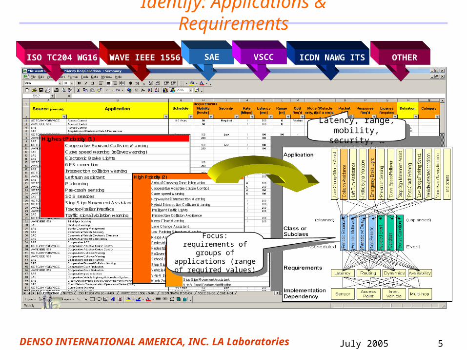
Identify: Applications & Requirements
ISO TC204 WG16 WAVE IEEE 1556 SAE VSCC ICDN NAWG ITS OTHER
Highest Priority (1)Cooperative Forward Collision Warning
Curve speed warning (rollover warning)
Electronic Brake Lights
GPS correction
Intersection collision warning
Left turn assistant
Platooning
Pre-crash sensing
SOS services
Stop Sign Movement Assistance
Tractor-Trailer Interface
Traffic signal violation warning
High Priority (2)Animal Crossing Zone Information
Cooperative Adaptive Cruise Control
Curve speed warning
HighwayRail Intersection Warning
Hybrid Intersection Collision Warning
Intelligent Traffic Lights
Intersection Collision Avoidance
Keep Clear' Warning
Lane Change Assistant
Low Parking Structure Warning
Merge Assistant
Pedestrian Crossing Information
Pedestrian/Children Warning
Rollover Warning
School Zone Warning
Stop Sign Warning
Vehicle-based Road Condition Warning
V-to-V Intersection Collision Warning
Work Zone Warning
Medium-High Priority (3)Emergency electronic brake lights
Instant Problem Messaging
Intelligent On-ramp Metering
Onboard Safety Data Transfer
Sign Information
Stop Sign Movement Assistant
V-to-V Road Feature Notification
Focus:requirements of groups of applications (range
of required values)
Focus:requirements of groups of applications (range
of required values)
Latency, range, mobility, security,
…
Latency, range, mobility, security,
…

July 2005DENSO INTERNATIONAL AMERICA, INC. LA Laboratories
6
Identify: Vehicular applications requirements
Top 7 Vehicle Safety Applications
• Intersection Collision Warning and Avoidance (Vehicle-to-Roadside-to-Vehicle)
• Left Turn Assistance (Vehicle-to-Vehicle)
• Cooperative Forward Collision Warnings (Vehicle-to-Vehicle)
• Pre-crash sensing (Vehicle-to-Vehicle)
• Emergency Electronic Brake light Signaling (Vehicle-to-Vehicle)
• Curve Speed/Rollover Warnings (Vehicle-to-Roadside-to-Vehicle)
• Pre-crash Sensing (Vehicle-to-Vehicle)
Preliminary Common Communications System Requirements• 50 - 100 ms access latency and update rates• 250+ km/hr mobility• Scalable on the basis of vehicle traffic density• Dynamic message routing• 10 - 500 m radio link range• Shared communication channel • Message payload 2 - 5 kbytes• Data rates 2 - 12 Mbps

July 2005DENSO INTERNATIONAL AMERICA, INC. LA Laboratories
7
Identify: Technology improvement
Channelization Scheme for Vehicle/Public Safety & Private Applications
Channelization solution to:• provide priority to vehicle/public safety message traffic• provide guaranteed and configurable message latency • allow channel capacity to be adaptively allocated
CH 1725860 MHz
CH 1745870 MHz
CH 1765880 MHz
CH 1785890 MHz
CH 1805900 MHz
CH 1825910 MHz
CH 1845920 MHz
ServiceChannel
High PriorityVehicle Safety
ServiceChannel
ServiceChannel
ServiceChannel
ServiceChannel
ServiceChannel
ControlChannel

July 2005DENSO INTERNATIONAL AMERICA, INC. LA Laboratories
8
Innovate: i-Channel Main Goals
• Prioritization– Public/Vehicle Safety is guaranteed highest priority– Channelization latency is predictable and configurable
• Synchronization– RSU not necessary for synchronization– Messaging is organized into Safety/Non-Safety time slots– Provides synchronization in overlapping RSU communication zones– No restrictions EXCEPT channel switching priority based on i-Channel rules– Non-Safety operation is flexible as long as i-Channel rules are followed
• Adaptive Channel Access– Allows available system capacity to be allocated to Non-Safety when Public
Safety is not needed– Allows full system capacity to be allocated to Public Safety when necessary
Main Features: Prioritizes Safety, reduces latency, supports non-RSU communications.
July 2005DENSO INTERNATIONAL AMERICA, INC. LA Laboratories
9
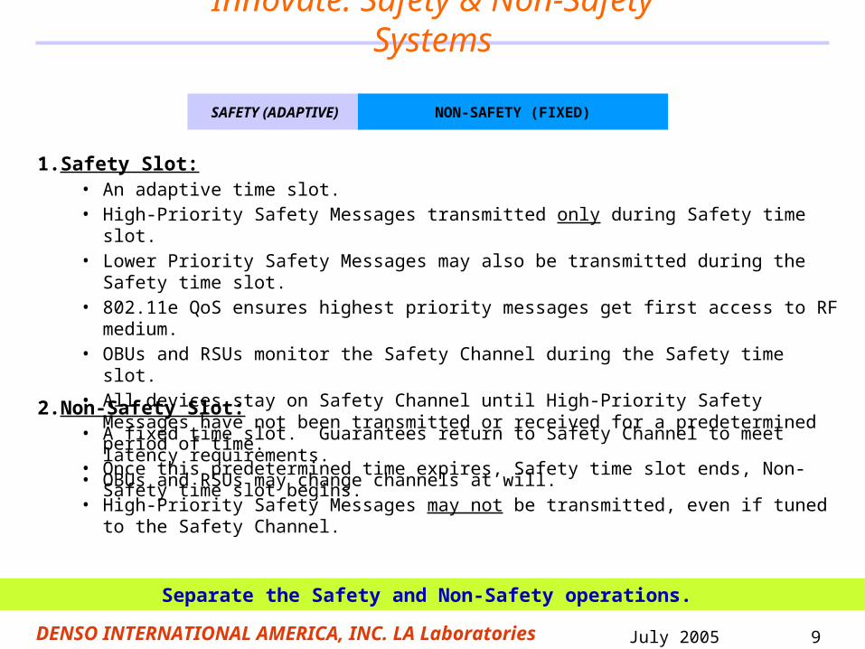
1. Safety Slot:• An adaptive time slot. • High-Priority Safety Messages transmitted only during Safety time slot. • Lower Priority Safety Messages may also be transmitted during the Safety time slot. • 802.11e QoS ensures highest priority messages get first access to RF medium. • OBUs and RSUs monitor the Safety Channel during the Safety time slot. • All devices stay on Safety Channel until High-Priority Safety Messages have not been
transmitted or received for a predetermined period of time. • Once this predetermined time expires, Safety time slot ends, Non-Safety time slot begins.
Innovate: Safety & Non-Safety Systems
Separate the Safety and Non-Safety operations.
2. Non-Safety Slot:• A fixed time slot. Guarantees return to Safety Channel to meet latency requirements. • OBUs and RSUs may change channels at will. • High-Priority Safety Messages may not be transmitted, even if tuned to the Safety Channel.
SAFETY (ADAPTIVE) NON-SAFETY (FIXED)

July 2005DENSO INTERNATIONAL AMERICA, INC. LA Laboratories
10
Innovate: Architectural Concept
Focus: Specification of control mechanism for channel/system isolation.
SafetyCH Non-Safety CH(s)
i-ChannelChannel
ManagementEntity
MAC/PHYMain Radio
Non-Safety SystemAccess
Channel Mux/Demux (CHMUX)
Safety SystemAccess
Non-Safety SystemUpper-Layers
Safety SystemUpper-Layers

July 2005DENSO INTERNATIONAL AMERICA, INC. LA Laboratories
11
Innovate: i-Channel Parameters
TNS-TX Time left over for Non-Safety Communication. This time period is fixed to TNS – (2 x TTUNE).
TIDLE Idle time that follows the last High Priority Safety Message (TX or RX).
TTUNE Time allocated for receiver settling after a channel change.
TNS Time allocated for Low Priority Non-Safety Communication. This time period is fixed.
TNS
TIDLE
Last HP
TTUNE
Tc = One Adaptive I-Channel Cycle
First HP
First LP or NS
Last LP or NS
TTUNETNS-TX
July 2005DENSO INTERNATIONAL AMERICA, INC. LA Laboratories
12
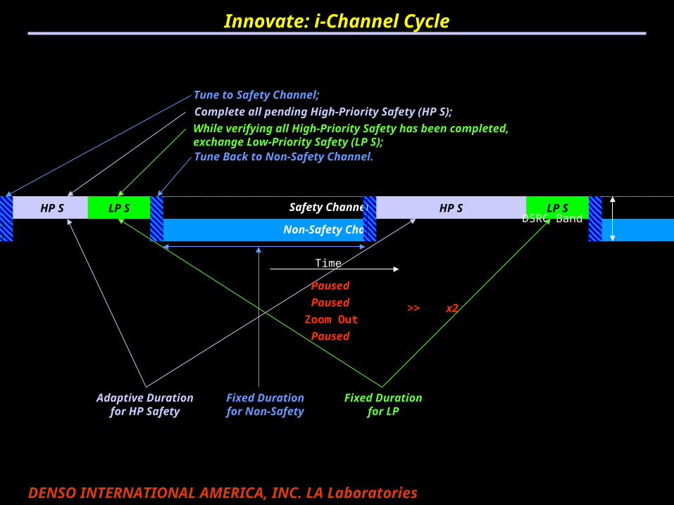
Non-Safety Channel(s)
Safety Channel
Zoom Out
HP S LP SHP S LP S HP S LP S
Paused
HP S LP S
Tune Back to Non-Safety Channel.
Tune to Safety Channel;
Complete all pending High-Priority Safety (HP S);
While verifying all High-Priority Safety has been completed, exchange Low-Priority Safety (LP S);
HP S LP S HP S LP S
Paused
Fixed Durationfor Non-Safety
Adaptive Durationfor HP Safety
Paused
Time
DSRC Band
>> x2
Innovate: i-Channel Cycle
Fixed Durationfor LP

July 2005DENSO INTERNATIONAL AMERICA, INC. LA Laboratories
13
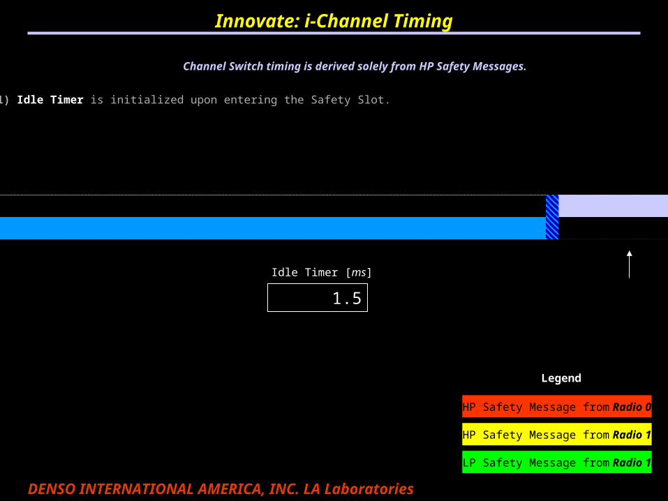
1) T idle InitInnovate: i-Channel Timing
Channel Switch timing is derived solely from HP Safety Messages.
Non-Safety Channel(s)
Safety Channel
Idle Timer [ms]
0
(1) Idle Timer is initialized upon entering the Safety Slot.
HP Safety Message from Radio 0
HP Safety Message from Radio 1
Legend
LP Safety Message from Radio 1
July 2005DENSO INTERNATIONAL AMERICA, INC. LA Laboratories
14
T idle = 1.5
Channel Switch timing is derived solely from HP Safety Messages.
Idle Timer [ms]
1.5
(1) Idle Timer is initialized upon entering the Safety Slot.
Innovate: i-Channel Timing
HP Safety Message from Radio 0
HP Safety Message from Radio 1
Legend
LP Safety Message from Radio 1

July 2005DENSO INTERNATIONAL AMERICA, INC. LA Laboratories
15
2) HP Radio 0
Channel Switch timing is derived solely from HP Safety Messages.
Idle Timer [ms]
0
(2) Idle Timer is reset every time a HP Safety message is received OR transmitted by any OBU or RSU in the network.
(1) Idle Timer is initialized upon entering the Safety Slot.
Radio 0 HP
Innovate: i-Channel Timing
HP Safety Message from Radio 0
HP Safety Message from Radio 1
Legend
LP Safety Message from Radio 1

July 2005DENSO INTERNATIONAL AMERICA, INC. LA Laboratories
16
T idle = 1.0
Channel Switch timing is derived solely from HP Safety Messages.
Idle Timer [ms]
1.0
(2) Idle Timer is reset every time a HP Safety message is received OR transmitted by any OBU or RSU in the network.
(1) Idle Timer is initialized upon entering the Safety Slot.
Radio 0 HP
Innovate: i-Channel Timing
HP Safety Message from Radio 0
HP Safety Message from Radio 1
Legend
LP Safety Message from Radio 1

July 2005DENSO INTERNATIONAL AMERICA, INC. LA Laboratories
17
HP Radio 1
Channel Switch timing is derived solely from HP Safety Messages.
Idle Timer [ms]
Radio 0 HP Radio 1 HP
(2) Idle Timer is reset every time a HP Safety message is received OR transmitted by any OBU or RSU in the network.
(1) Idle Timer is initialized upon entering the Safety Slot.
0
Innovate: i-Channel Timing
HP Safety Message from Radio 0
HP Safety Message from Radio 1
Legend
LP Safety Message from Radio 1
July 2005DENSO INTERNATIONAL AMERICA, INC. LA Laboratories
18
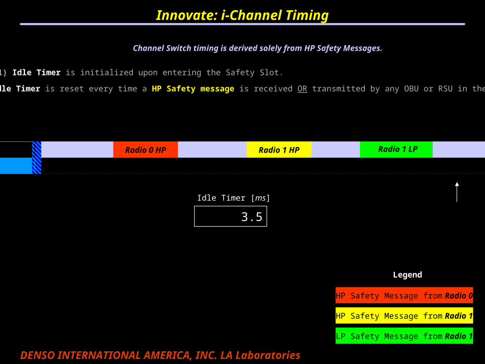
T idle = 3.5
Channel Switch timing is derived solely from HP Safety Messages.
Idle Timer [ms]
(2) Idle Timer is reset every time a HP Safety message is received OR transmitted by any OBU or RSU in the network.
(1) Idle Timer is initialized upon entering the Safety Slot.
3.5
Radio 0 HP Radio 1 HP
Innovate: i-Channel Timing
HP Safety Message from Radio 0
HP Safety Message from Radio 1
Legend
LP Safety Message from Radio 1
Radio 1 LP

July 2005DENSO INTERNATIONAL AMERICA, INC. LA Laboratories
19
T idle Timeout
Channel Switch timing is derived solely from HP Safety Messages.
Idle Timer [ms]
(2) Idle Timer is reset every time a HP Safety message is received OR transmitted by any OBU or RSU in the network.
(3) The Idle Timer times out when it reached a predetermined value. Then, the radio MAY tune away from safety.
(4) Even if the radio does not tune away during the fixed non-safety period, HP Safety messages SHALL NOT be sent during that time.
(1) Idle Timer is initialized upon entering the Safety Slot.
Timeout
Radio 0 HP Radio 1 HP
Innovate: i-Channel Timing
Radio 1 LP
HP Safety Message from Radio 0
HP Safety Message from Radio 1
Legend
LP Safety Message from Radio 1

July 2005DENSO INTERNATIONAL AMERICA, INC. LA Laboratories
20
Nodes enter High Awareness mode (HA) periodically
Innovate: How do nodes and networks synchronize?
High Awareness = Stay on Safety Channel during Non-Safety period.
Nodes enter HA, e.g. every 1 or 2 seconds, andNodes enter HA, e.g. every 1 or 2 seconds, andstay on the safety channel during the next NS period stay on the safety channel during the next NS period
looking for other nodes within communication distance.looking for other nodes within communication distance.
HP NSLP HP HALP HP NSLP HP NSLP HP NSLP HP NSLP HP NSLP HP NSLP
HP NSLP HP NSLP HP NSLP HP HALP HP NSLP HP NSLP HP NSLP HP NSLP
HP NSLP HP NSLP HP NSLP HP NSLP HP NSLP HP NSLP HP HALP HP NSLP
HP HALP HP NSLP HP NSLP HP NSLP HP NSLP HP NSLP HP NSLP HP NSLP
t0 tf
Nodes in a network enter High Awareness mode at different times
Node 0
Node 1
Node 2
Node 3

July 2005DENSO INTERNATIONAL AMERICA, INC. LA Laboratories
21
Innovate: Follow the Leader
TNS = TSRCHTIDLE
Last HP
Go to High Awareness
THA Timeout
In High Awareness “Follow Me” Returning
TIDLE
HPTX
Following Searching
Follow Me!
LEADER
FOLLOWERS
Other Network Detected
RX Follow Me Packet
Last HP
Last HP
TIDLE
TIDLE
“Follow the Leader” allows two clusters to join very quickly.
July 2005DENSO INTERNATIONAL AMERICA, INC. LA Laboratories
22
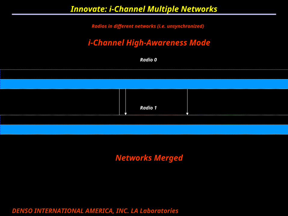
Innovate: i-Channel Multiple Networks
Radio 0
Radio 1
Radios in the same network (i.e. synchronized)
Radios in different networks (i.e. unsynchronized)
i-Channel High-Awareness Mode
HP S LP S High-Awareness (instead of NS) HP S LP S
HP STX
RX F
F Acquire Radio 0 Network LP SHP S
Networks Merged

July 2005DENSO INTERNATIONAL AMERICA, INC. LA Laboratories
23
Innovate: High Awareness
Simulation data shows switching times independent of network size and mobility
Equal Size ClustersUnequal Size Clusters
Equal Size ClustersUnequal Size Clusters
THA = 1.0 THA = 1.0

July 2005DENSO INTERNATIONAL AMERICA, INC. LA Laboratories
24
• All channel switching causes delays,
• unless a radio is camped on a channel continuously.
• All 802.11 systems have delays for medium access.
• CSMA/CA access and back-off and
• impacts of hidden nodes, interference, propagation delay, …
• 802.11 packet latency depends on circumstances, environment, number of nodes, dynamics, loading, …
• How can we isolate these impacts to determine the performance of a given channel switching method?
How can we effectively compare channel switching methods?
Implement: Channelization Latency Problem

July 2005DENSO INTERNATIONAL AMERICA, INC. LA Laboratories
25
Implement: Useful Measure of Latency
DEFINITION: Channelization latency is the component of packet latency attributable to delays caused by the multi-channel management system.
Time delay between:• Packet arrival in MAC transmit queue from upper layer, and
• Radio tuned to channel corresponding to that MAC queue.
Thus, Packet Latency =Channelization latency
+ Queue delay
+ Access delay
+ Propagation delay
+ Process delay in receiver
Channelization Latency is a measure of the efficiency of the channel switching.

July 2005DENSO INTERNATIONAL AMERICA, INC. LA Laboratories
26
Implement: Expected Latency (analytic)
___ HP Safety___ LP Safety___ Non-Safety
• Computation of expected value of channelization latency according to:
• Probability of packet arrival relative to channel switching system time;
• Probability of channel change latency given load.
T_IDLE = 0.005
T_NS = 0.050
T_TUNE = 0.002
Expected Latency for HP and LP Safety and Non-Safety

July 2005DENSO INTERNATIONAL AMERICA, INC. LA Laboratories
27
Implement: Measured Latency (simulations)
• Measured actual channelization latency from ns2 simulations with varying degrees of high priority safety load.
T_IDLE = 0.005
T_NS = 0.050
T_TUNE = 0.002

July 2005DENSO INTERNATIONAL AMERICA, INC. LA Laboratories
28
ITS / DSRC prototyping
Implement: feasibility platform

July 2005DENSO INTERNATIONAL AMERICA, INC. LA Laboratories
29
WAVE Prototype Communications Module Support Tool
10 / 20 MHz BandWidth
Selection
WAVE Frequency Channel Selection Variable Data
Rate
Adjustable TX Pout (1dB incremental)
Implement: Tools for prototype
T-ns setting T-idle setting T-High Awareness setting
t-ns

July 2005DENSO INTERNATIONAL AMERICA, INC. LA Laboratories
30
Insure: Expected vs. Measured Latency (prototype)
Measurements using radio module prototype confirm Analytical & Simulation analysis.
Measured packet latency from WRM prototypes with very low loading and few units:• low loading approximates zero queue delay; • few units approximates zero access delay;• thus, packet latency approximates channelization latency.
0102030405060708090
100110120130140150
0 0.1 0.2 0.3 0.4 0.5 0.6 0.7 0.8 0.9 1
Safety Offered Load
Late
ncy (
ms)
Measured HP Safety Expected HP Safety Measured LP Safety
Expected LP Safety Measured Non Safety Expected Non Safety
T_IDLE = 0.005
T_NS = 0.100
T_TUNE = 0.002
July 2005DENSO INTERNATIONAL AMERICA, INC. LA Laboratories
31
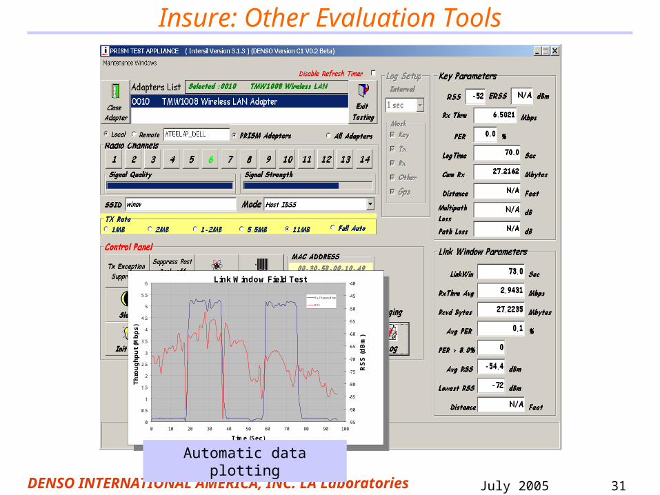
Insure: Other Evaluation Tools
Link Window Field Test
0
0.5
1
1.5
2
2.5
3
3.5
4
4.5
5
5.5
6
0 10 20 30 40 50 60 70 80 90 100
Time (Sec)
Th
rou
gh
pu
t (M
bp
s)
-95
-90
-85
-80
-75
-70
-65
-60
-55
-50
-45
-40
RS
S (
dB
m)
Rx_Thruput_M bps
RSS
Link Window Field Test
0
0.5
1
1.5
2
2.5
3
3.5
4
4.5
5
5.5
6
0 10 20 30 40 50 60 70 80 90 100
Time (Sec)
Th
rou
gh
pu
t (M
bp
s)
-95
-90
-85
-80
-75
-70
-65
-60
-55
-50
-45
-40
RS
S (
dB
m)
Rx_Thruput_M bps
RSS
Automatic data plotting

July 2005DENSO INTERNATIONAL AMERICA, INC. LA Laboratories
32
1 50 99 148 197 246 295 3440
2
4
6
8
10
12
14
16
18
20
22
24
26
28
30
Index into RSU Drive-Away Time (in 1/4 sec increments)
Measured Broadcast Throughput by Burst Rate Vs 1/4 Sec Time IndexOBU driving away from RSU (54Mbps burst data not available)
483624181296
6
24
18
12
9
48
36
Th
rou
gh
pu
t in
Mb
ps
Rates (Mbps)
802.11a Burst Max Ad Hoc UDP-BRate (Mbps) Throughput (Mbps)
54 28.448 26.536 22.124 16.818 13.412 9.69 7.5
6 5.2
Link Window Distance ~ 2000 meters
99.3% 98.5%99.9% 99.3% 99.8% 98.2%
88.1%
76.6%
67.2%
99.4% 98.3% 99.3%97.5%
95.7%
85.8%
74.7%
66.1%
98.0%96.1%
98.2%96.6% 95.8%
85.9%
72.4%
63.0%
95.9% 94.6% 95.4%93.1%
91.8%
82.5%
70.3%
61.4%
55%
60%
65%
70%
75%
80%
85%
90%
95%
100%
Avera
ge P
SR
(%
)
6 9 12 18 24 36 48 54
802.11A Burst Rates (Mbps)
Packet Size(Bytes)
Average V2V PSR Vs 802.11A Burst Rate (Mbps) & Packet Size (Bytes), 40% link blockage
99.8% 99.6%
89.5%
78.8%
69.4%
97.2%V2V PSR
STATISTICS
98.5%99.3%99.9% 99.3% 99.8%
98.2%96.4%
Insure: Other Evaluation Tools

July 2005DENSO INTERNATIONAL AMERICA, INC. LA Laboratories
33
Conclusion
• Identified– Application requirements are the center point– Analyze technology deficiencies
• Innovated solutions– Prioritize, channelize, synchronize with low latency
• Implemented– Simulation and feasibility HW & SW
• Insured– Match theory/simulation to implementation results– Test tools validate innovative implementation