assembletransmission group 15
TRANSCRIPT

Group 15Assemble Transmission
TS15509,00000F0 -19-02AUG13-1/1
TS15509,00000F1 -19-04SEP18-1/1
TS15509,00000F2 -19-02AUG13-1/1
List of ReferencesBelow is a list of all items within this group.
Essential, Recommended, and Dealer Fabricated Tools50A—15
Other Material 50A—15
Specifications 50A—15
Install Bearing Cups—IVT™
Install CU Idler—IVT™
Install Planetary Input Gears—IVT™
Install Synchronizer—IVT™
Install PTO Drive Gear—IVT™
Install Front Cover—IVT™
Install Output-to-MFWD Housing—IVT™
Install Planetary Ring Gear and RU Idler—IVT™
Install Hydrostatic Assembly—IVT™
Install Planetary Assembly—IVT™
Install Reverse Brake and High-Low ClutchAssembly—IVT™
Install Transmission Output Shaft—IVT™
Install Rear Cover—IVT™
Install Manifold—IVT™
Install Scavenge Pump—IVT™
Adjust Bearings—IVT™
Install Auxiliary Drive Shaft—IVT™
Clutch Element Leak Check—IVT™
Essential, Recommended, and DealerFabricated Tools 50A—15NOTE: For further information, see SERVICEGARD™
online tool Catalog.
Below are tools listed in this group.
DFRW212 Leak Test Assembly
D01045AA Disk Set
D05114ST Spanner Wrench
JDG19 Lifting Eyes
JDG1666 Park Brake Release Hand Pump Kit
JDG1758 Seal Installer
JDG1763 Lifting Eye
JDG1765 CU Idler Shaft Holding Tool
JDG1841 Bearing Installer
JDG1861 Seal Installer
JDG1888 Shift Valve Plug
JDG10049 Seal Installer
JDG10232 Bearing Installer
Other Material 50A—15Number Name Use
PM38657 (U.S.)PM38628 (Canadian)17430 Loctite™ (U.S.)
High Flex Form-In-Place Gasket Used to seal transmission housings.
TM119119 (03AUG20) 50A-15-1 8245R, 8270R, 8295R, 8320R, 8335R, 8345R,8370R, 8400R, 8R-2304, and 8R-3004 Tractors
080420
PN=567

Assemble Transmission
Continued on next page LN71218,000347C -19-14OCT19-1/2
Specifications 50A—15Item Measurement Specification
Planetary Input Gear AssemblyBearing Frame Cap Screws
Torque 125 N·m(92 lb.-ft.)
Planetary Input Gear Assembly End Play 0.00—0.15 mm(0.000—0.006 in.)
Bearing Adjusting Ring SocketHead Screw
Torque 50 N·m(36 lb.-ft.)
PTO Gear-to-Front HousingCap Screw
Torque 125 N·m(92 lb.-ft.)
Front Cover Cap Screws (M20) Torque 430 N·m(318 lb.-ft.)
Front Cover Cap Screws (M12) Torque 125 N·m(92 lb.-ft.)
Input Shaft End Play 0.03—0.13 mm(0.001—0.005 in.)
CU Idler Shaft Nut Torque 200 N·m(148 lb.-ft.)
CU Idler Shaft End Play 0.00—0.10 mm(0.000—0.004 in.)
Output-to-MFWD Housing AssemblyCap Screws
Torque 125 N·m(92 lb.-ft.)
Output Shaft End Play 0.00—0.15 mm(0.000—0.006 in.)
Output-to-ILS Housing AssemblyCap Screws
Torque 125 N·m(92 lb.-ft.)
Front PTO Drive Cover Cap Screws Torque 70 N·m(52 lb.-ft.)
RU Idler Retaining Nut Torque 200 N·m(148 lb.-ft.)
Bearing Retaining Strap Screws Torque 50 N·m(37 lb·ft)
Reverse Brake Housing Cap Screws Torque 106 N·m(78 lb.-ft.)
Rear Housing-to-Center HousingCap Screws
Torque 125 N·m(92 lb.-ft.)
Ground Stud Torque 105 N·m(77 lb.-ft.)
Manifold-to-Rear Cover SocketHead Screws
Torque 85 N·m(62 lb.-ft.)
Plugs Torque 85 N·m(62 lb.-ft.)
Manifold-to-Rear Cover Cap Screws Torque 125 N·m(92 lb.-ft.)
Oil Pump-to-Manifold Cap Screws Torque 125 N·m(92 lb.-ft.)
TM119119 (03AUG20) 50A-15-2 8245R, 8270R, 8295R, 8320R, 8335R, 8345R,8370R, 8400R, 8R-2304, and 8R-3004 Tractors
080420
PN=568

Assemble Transmission
LN71218,000347C -19-14OCT19-2/2
TS15509,00000F4 -19-25SEP13-1/2
TS15509,00000F4 -19-25SEP13-2/2
Item Measurement Specification
Planetary Output End Play 0.00—0.15 mm(0.000—0.006 in.)
Transmission Output Shaft End Play 0.00—0.15 mm(0.000—0.006 in.)
Output Shaft Seal Depth 0.50 mm(0.020 in.)
Bearing Cover/Seal Plate CapScrews
Torque 35 N·m(25 lb.-ft.)
Auxiliary Drive Pulley Cap Screw Torque 125 N·m(92 lb.-ft.)
Shift Solenoids Torque 35 N·m(26 lb.-ft.)
Install Bearing Cups—IVT™1. Use 110 mm (4-5/16 in.) driver disk to install bearing
cups (A).
A—Bearing Cups (3 used)
RXA0125745—UN—04APR12
2. Clean sealing surface (A).
3. Use a 112 mm (4-3/8 in.) driver disk to install bearingcup (B).
4. Install NEW hydrostatic module isolators (C).
5. Proceed to Install CU Idler—IVT™ in this group.
A—Sealing SurfaceB—Bearing Cup
C—Hydrostatic Isolators (2used)RXA0125746—UN—04APR12
TM119119 (03AUG20) 50A-15-3 8245R, 8270R, 8295R, 8320R, 8335R, 8345R,8370R, 8400R, 8R-2304, and 8R-3004 Tractors
080420
PN=569
Assemble Transmission
TS15509,00000F5 -19-25SEP13-1/2
TS15509,00000F5 -19-25SEP13-2/2
Continued on next page TS15509,00000F6 -19-25SEP13-1/9
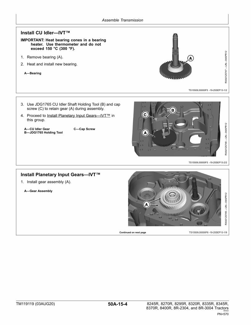
Install CU Idler—IVT™IMPORTANT: Heat bearing cones in a bearing
heater. Use thermometer and do notexceed 150 °C (300 °F).
1. Remove bearing (A).
2. Heat and install new bearing.
A—Bearing
RXA0125747—UN—04APR12
3. Use JDG1765 CU Idler Shaft Holding Tool (B) and capscrew (C) to retain gear (A) during assembly.
4. Proceed to Install Planetary Input Gears—IVT™ inthis group.
A—CU Idler GearB—JDG1765 Holding Tool
C—Cap Screw
RXA0125748—UN—04APR12
Install Planetary Input Gears—IVT™1. Install gear assembly (A).
A—Gear Assembly
RXA0125749—UN—04APR12
TM119119 (03AUG20) 50A-15-4 8245R, 8270R, 8295R, 8320R, 8335R, 8345R,8370R, 8400R, 8R-2304, and 8R-3004 Tractors
080420
PN=570
Assemble Transmission
TS15509,00000F6 -19-25SEP13-2/9
TS15509,00000F6 -19-25SEP13-3/9
Continued on next page TS15509,00000F6 -19-25SEP13-4/9
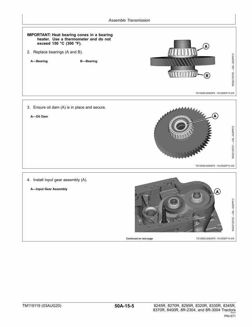
IMPORTANT: Heat bearing cones in a bearingheater. Use a thermometer and do notexceed 150 °C (300 °F).
2. Replace bearings (A and B).
A—Bearing B—Bearing
RXA0125750—UN—04APR12
3. Ensure oil dam (A) is in place and secure.
A—Oil Dam
RXA0125751—UN—04APR12
4. Install input gear assembly (A).
A—Input Gear Assembly
RXA0125752—UN—04APR12
TM119119 (03AUG20) 50A-15-5 8245R, 8270R, 8295R, 8320R, 8335R, 8345R,8370R, 8400R, 8R-2304, and 8R-3004 Tractors
080420
PN=571

Assemble Transmission
TS15509,00000F6 -19-25SEP13-5/9
TS15509,00000F6 -19-25SEP13-6/9
Continued on next page TS15509,00000F6 -19-25SEP13-7/9
5. Remove socket head screw (A) from bearing support(C).
6. Loosen adjusting ring (B).
A—Socket Head ScrewB—Adjusting Ring
C—Bearing Support
RXA0125753—UN—04APR12
7. Install bearing cup (A) in bearing frame.
A—Bearing Cup
RXA0125754—UN—04APR12
8. Install bearing frame (A). Tighten planetary inputgear assembly bearing frame cap screws (B) tospecification.
SpecificationPlanetary Input GearAssembly Bearing FrameCap Screws—Torque..................................................................125 N·m
(92 lb.-ft.)
9. Roll gears several turns to seat bearing rollers.
10. Install dial indicator (C).
11. Turn adjusting ring (D) to set end play.Specification
Planetary Input GearAssembly—End Play........................................................0.00—0.15 mm
(0.000—0.006 in.)
RXA0125755—UN—04APR12
A—Bearing FrameB—Planetary Input Gear
Assembly Bearing FrameCap Screws (5 used)
C—Dial IndicatorD—Adjusting Ring
TM119119 (03AUG20) 50A-15-6 8245R, 8270R, 8295R, 8320R, 8335R, 8345R,8370R, 8400R, 8R-2304, and 8R-3004 Tractors
080420
PN=572

Assemble Transmission
TS15509,00000F6 -19-25SEP13-8/9
TS15509,00000F6 -19-25SEP13-9/9
Continued on next page TS15509,00000F7 -19-04SEP13-1/2
12. Install new bearing adjusting ring socket head screw(A) in threaded hole (B) closest to aligning with a notchin adjusting ring (C). Tighten to specification.
SpecificationBearing AdjustingRing Socket HeadScrew—Torque..............................................................................50 N·m
(36 lb.-ft.)
A—Bearing Adjusting RingSocket Head Screw
B—Threaded Hole
C—Adjusting Ring
RXA0125756—UN—04APR12
13. Install gear assembly (A).
14. Proceed to Install Synchronizer—IVT™ in this group.
RXA0125757—UN—04APR12
Install Synchronizer—IVT™1. Install CU gear assembly (A) and retaining ring (B).
A—CU Idler Gear B—Retaining Ring
RXA0125758—UN—04APR12
TM119119 (03AUG20) 50A-15-7 8245R, 8270R, 8295R, 8320R, 8335R, 8345R,8370R, 8400R, 8R-2304, and 8R-3004 Tractors
080420
PN=573

Assemble Transmission
TS15509,00000F7 -19-04SEP13-2/2
TS15509,00000F8 -19-18JAN19-1/4
Continued on next page TS15509,00000F8 -19-18JAN19-2/4
2. Install synchronizer and shift assemblies (A).
3. Install retaining ring (B).
4. Proceed to Install PTO Drive Gear—IVT™ in thisgroup.
A—Synchronizer Assemblyand Shift Assembly
B—Retaining Ring
RXA0125759—UN—04APR12
Install PTO Drive Gear—IVT™1. For tractors not equipped with front PTO, perform
the following:
NOTE: NOTE: Due to manufacturing error, tool maybe marked JDG110232. Press bearings (B) inonly enough to install retaining ring (A).
a. Replace bearings (B) with JDG10232 BearingInstaller.
A—Retaining Ring B—Bearings (2 used) RXA0125760—UN—04APR12
b. Install washer (A), gear (B), sleeve (C), and PTOgear-to-front housing cap screw (D). Tighten tospecification.
SpecificationPTO Gear-to-FrontHousing CapScrew—Torque............................................................................125 N·m
(92 lb.-ft.)
c. Proceed to Install Front Cover—IVT™ in this group.
A—WasherB—PTO Gear
C—SleeveD—PTO Gear-to-Front Housing
Cap Screw
RXA0125761—UN—04APR12
TM119119 (03AUG20) 50A-15-8 8245R, 8270R, 8295R, 8320R, 8335R, 8345R,8370R, 8400R, 8R-2304, and 8R-3004 Tractors
080420
PN=574

Assemble Transmission
TS15509,00000F8 -19-18JAN19-3/4
TS15509,00000F8 -19-18JAN19-4/4
Continued on next page TS15509,00000F9 -19-02FEB17-1/14
2. For tractors equipped with front PTO, perform thefollowing:
a. Install sealing rings (A) and plug (B).
A— Sealing Rings (2 used) B— Plug
RXA0125762—UN—04APR12
IMPORTANT: Snap ring (B) should face the gear.
b. Install bearing (A) and snap ring (B) into housing.
c. Install PTO drive gear assembly (C) into housing.
d. Proceed to Install Front Cover—IVT™ in this group.
A—BearingB—Snap Ring
C—PTO Drive Gear Assembly
RXA0125763—UN—04APR12
Install Front Cover—IVT™1. Install front housing (A). Tighten front cover cap
screws (B and C) to specification.Specification
Front Cover Cap Screws(M20)—Torque............................................................................430 N·m
(318 lb.-ft.)Front Cover Cap Screws(M12)—Torque............................................................................125 N·m
(92 lb.-ft.)
2. Rotate input shaft (D) several turns to seat bearings.
3. Use dial indicator to measure shaft end play.Specification
Input Shaft—End Play......................................................0.03—0.13 mm(0.001—0.005 in.)
RXA0125764—UN—04APR12
A—Transmission FrontHousing
B—Front Cover M20 CapScrews (9 used)
C—Front Cover M12 CapScrews (8 used)
D—Input Shaft
TM119119 (03AUG20) 50A-15-9 8245R, 8270R, 8295R, 8320R, 8335R, 8345R,8370R, 8400R, 8R-2304, and 8R-3004 Tractors
080420
PN=575

Assemble Transmission
TS15509,00000F9 -19-02FEB17-2/14
TS15509,00000F9 -19-02FEB17-3/14
Continued on next page TS15509,00000F9 -19-02FEB17-4/14
4. Remove front housing.
5. Remove bearing cup (A).
6. Add or remove shims (B) as necessary to achievecorrect end play.
IMPORTANT: Ensure bearing cup is fullyseated in housing.
7. Reinstall shim pack and bearing cup.
A—Bearing Cup B—Shims
RXA0125765—UN—04APR12
8. Install O-ring (A) and seal (B) into front cover sealgroove (C).
A—O-ringB—Seal
C—Seal Groove
RXA0125766—UN—04APR12
A
B
RXA0082379—UN—15JU
L05
9. Install gear (A) and spacer (B).
10. Install bearing (C).
A—GearB—Spacer
C—Bearing
RXA0125767—UN—04APR12
TM119119 (03AUG20) 50A-15-10 8245R, 8270R, 8295R, 8320R, 8335R, 8345R,8370R, 8400R, 8R-2304, and 8R-3004 Tractors
080420
PN=576

Assemble Transmission
TS15509,00000F9 -19-02FEB17-5/14
TS15509,00000F9 -19-02FEB17-6/14
Continued on next page TS15509,00000F9 -19-02FEB17-7/14
11. Install line (A).
12. Install gear assembly (B).
13. Install O-rings (C and D).
A—LineB—Gear Assembly
C—O-ringD—O-ring
RXA0125768—UN—04APR12
14. For ILS transmissions, perform the following:
• Install O-rings (A).A—O-rings (2 used)
RXA0125788—UN—10APR12
IMPORTANT: Excessive PM38657 High FlexForm-In-Place Gasket can block lube portsif applied to thick.
NOTE: A small roller can be used to apply PM38657High Flex Form-In-Place Gasket.
15. Apply a thin coating of PM38657 High FlexForm-In-Place Gasket on sealing surface (A). Avoidover applying in passages (B).
A—Sealing Surface B—Lube Passages
RXA0156416—UN—25JAN17
TM119119 (03AUG20) 50A-15-11 8245R, 8270R, 8295R, 8320R, 8335R, 8345R,8370R, 8400R, 8R-2304, and 8R-3004 Tractors
080420
PN=577

Assemble Transmission
TS15509,00000F9 -19-02FEB17-8/14
TS15509,00000F9 -19-02FEB17-9/14
Continued on next page TS15509,00000F9 -19-02FEB17-10/14
16. For tractors not equipped with front PTO, performthe following: Install front housing (A), front coverM12 cap screws (B), and front cover M20 cap screwswith washers (C). Tighten to specification.
SpecificationFront Cover Cap Screws(M12)—Torque............................................................................125 N·m
(92 lb.-ft.)Front Cover Cap Screws(M20)—Torque............................................................................430 N·m
(318 lb.-ft.)
A—Front HousingB—Front Cover M12 Cap
Screws (8 used)
C—Front Cover M20 Cap Screwwith Washers (9 used)
RXA0125789—UN—10APR12
17. For tractors equipped with front PTO, perform thefollowing: Install front housing (A), M12 cap screws(B), and M20 cap screws with washers (C). Tightento specification.
SpecificationFront Cover Cap Screws(M12)—Torque............................................................................125 N·m
(92 lb.-ft.)Front Cover Cap Screws(M20)—Torque............................................................................430 N·m
(318 lb.-ft.)
A—Front HousingB—M12 Cap Screws (8 used)
C—M20 Cap Screw withWashers (9 used)
RXA0125790—UN—10APR12
18. Install required shims (A) to achieve shaft end play.
19. Install bearing (B). Tighten CU idler shaft nut (C) tospecification.
SpecificationCU Idler ShaftNut—Torque................................................................................200 N·m
(148 lb.-ft.)
A—ShimsB—Bearing Cone
C—CU Idler Shaft Nut
RXA0125791—UN—10APR12
TM119119 (03AUG20) 50A-15-12 8245R, 8270R, 8295R, 8320R, 8335R, 8345R,8370R, 8400R, 8R-2304, and 8R-3004 Tractors
080420
PN=578

Assemble Transmission
TS15509,00000F9 -19-02FEB17-11/14
TS15509,00000F9 -19-02FEB17-12/14
Continued on next page TS15509,00000F9 -19-02FEB17-13/14
20. Remove cap screw (A) from JDG1765 CU Idler ShaftHolding Tool
A—Cap Screw
RXA0125792—UN—10APR12
21. Use dial indicator to check and adjust end play.Specification
CU Idler Shaft—EndPlay..................................................................................0.00—0.10 mm
(0.000—0.004 in.)
22. Add or remove shims under bearing to achieve correctend play.
23. Reinstall bearing and tighten NEW nut.
A—Dial Indicator
RXA0125793—UN—10APR12
24. Put Stake mark (A) into nut in shaft slot.
A—Staking
RXA0125794—UN—10APR12
TM119119 (03AUG20) 50A-15-13 8245R, 8270R, 8295R, 8320R, 8335R, 8345R,8370R, 8400R, 8R-2304, and 8R-3004 Tractors
080420
PN=579

Assemble Transmission
TS15509,00000F9 -19-02FEB17-14/14
TS15509,00000FA -19-21NOV14-1/12
Continued on next page TS15509,00000FA -19-21NOV14-2/12
25. Remove JDG1765 CU Idler Shaft Holding Tool.
26. Proceed to Install Output-to-MFWD Housing—IVT™in this group.
A—JDG1765 CU Idler ShaftHolding Tool
RXA0125795—UN—10APR12
Install Output-to-MFWD Housing—IVT™1. For tractors equipped with MFWD, perform the
following: Install bearing cup (A) and output housing(B). Tighten output-to-MFWD housing assembly capscrews (C) to specification.
SpecificationOutput-to-MFWDHousing Assembly CapScrews—Torque..........................................................................125 N·m
(92 lb.-ft.)
A—Bearing CupB—Housing
C—Output-to-MFWD HousingAssembly Cap Screws (4used)
RXA0125797—UN—10APR12
2. Use dial indictor to check shaft end play.Specification
Output Shaft—End Play...................................................0.00—0.15 mm(0.000—0.006 in.)
A—Dial IndicatorRXA0125796—UN—10APR12
TM119119 (03AUG20) 50A-15-14 8245R, 8270R, 8295R, 8320R, 8335R, 8345R,8370R, 8400R, 8R-2304, and 8R-3004 Tractors
080420
PN=580

Assemble Transmission
TS15509,00000FA -19-21NOV14-3/12
TS15509,00000FA -19-21NOV14-4/12
Continued on next page TS15509,00000FA -19-21NOV14-5/12
3. Calculate and install correct shims (A).
4. Install O-ring (B) and shaft seal (C).
A—ShimsB—O-ring
C—Shaft Seal
RXA0125798—UN—10APR12
NOTE: (See Repair Output Housing-to-MFWD—IVT™in group 10.)
5. Install O-ring (A).
A—O-ring
RXA0125799—UN—10APR12
6. Install housing assembly (A). Tighten output-to-MFWDhousing assembly cap screws (B) to specification.
SpecificationOutput-to-MFWDHousing Assembly CapScrews—Torque..........................................................................125 N·m
(92 lb.-ft.)
A—Housing Assembly B—Output-to-MFWD HousingAssembly Cap Screws (4used)
RXA0125800—UN—10APR12
TM119119 (03AUG20) 50A-15-15 8245R, 8270R, 8295R, 8320R, 8335R, 8345R,8370R, 8400R, 8R-2304, and 8R-3004 Tractors
080420
PN=581

Assemble Transmission
TS15509,00000FA -19-21NOV14-6/12
TS15509,00000FA -19-21NOV14-7/12
Continued on next page TS15509,00000FA -19-21NOV14-8/12
7. For tractors equipped with ILS, perform thefollowing: Install bearing cup (A) and output housing(B); then tighten output-to-ILS housing assembly capscrews (C) to specification.
SpecificationOutput-to-ILS HousingAssembly CapScrews—Torque..........................................................................125 N·m
(92 lb.-ft.)
A—Bearing CupB—Housing
C—Output-to-ILS HousingAssembly Cap Screws (4used)
RXA0125823—UN—09APR12
8. Use dial indicator (A) to check shaft end play.Specification
Output Shaft—End Play...................................................0.00—0.15 mm(0.000—0.006 in.)
A—Dial Indicator
RXA0125796—UN—10APR12
9. Calculate and install correct shims (A).
10. Install O-ring (B) and shaft seal (C).
A—ShimsB—O-ring
C—Shaft Seal
RXA0125798—UN—10APR12
TM119119 (03AUG20) 50A-15-16 8245R, 8270R, 8295R, 8320R, 8335R, 8345R,8370R, 8400R, 8R-2304, and 8R-3004 Tractors
080420
PN=582

Assemble Transmission
TS15509,00000FA -19-21NOV14-9/12
Continued on next page TS15509,00000FA -19-21NOV14-10/12
NOTE: (See Repair Output Housing-to-ILS™—IVT™in Group 10.)
11. Install O-ring (A).
A—O-ring
RXA0125824—UN—09APR12
12. Install housing assembly (A). Tighten output-to-ILShousing assembly cap screws (B) to specification.
SpecificationOutput-to-ILS HousingAssembly CapScrews—Torque..........................................................................125 N·m
(92 lb.-ft.)
A—Housing Assembly B—Output-to-ILS HousingAssembly Cap Screws (4used)
RXA0125825—UN—09APR12
TM119119 (03AUG20) 50A-15-17 8245R, 8270R, 8295R, 8320R, 8335R, 8345R,8370R, 8400R, 8R-2304, and 8R-3004 Tractors
080420
PN=583

Assemble Transmission
Continued on next page TS15509,00000FA -19-21NOV14-11/12
13. For tractors equipped with counterclockwise frontPTO, perform the following:
a. Press bearings (C) into cover (B) making sure snaprings (D) are facing up.
b. Install lower sprocket (E) and press inner race (F)onto shaft (G).
c. Install outer race (H) in front cover (B).
d. Install upper sprocket (I) and chains (J).
e. Align chains with lower sprocket (E) and install shaft(G).
f. Install cover (B) and front PTO drive cover capscrews (A). Tighten to specification.
SpecificationFront PTO Drive CoverCap Screws—Torque....................................................................70 N·m
(52 lb.-ft.)
A— Front PTO Drive Cover CapScrews (4 used)
B— CoverC— Bearings (2 used)D— Snap Rings (2 used)E— Lower Sprocket
F— Inner RaceG— ShaftH— Outer RaceI— Upper SprocketJ— Chains (2 used)
RXA0121827—UN—28OCT11
RXA0125300—UN—28FE
B12
RXA0125144—UN—16FE
B12
TM119119 (03AUG20) 50A-15-18 8245R, 8270R, 8295R, 8320R, 8335R, 8345R,8370R, 8400R, 8R-2304, and 8R-3004 Tractors
080420
PN=584

Assemble Transmission
TS15509,00000FA -19-21NOV14-12/12
14. For tractors equipped with clockwise front PTO,perform the following:
a. Press bearings (C) into cover (B) making sure snaprings (D) are facing up.
b. Install lower gear (E) and press inner race (F) ontoshaft (G).
c. Install outer bearing race (H) in front cover (B).
d. Install upper gear (I) and shaft (G).
e. Install cover (B) and front PTO drive cover capscrews (A). Tighten to specification.
SpecificationFront PTO Drive CoverCap Screws—Torque....................................................................70 N·m
(52 lb.-ft.)
15. Proceed to Install Planetary Ring Gear and RUIdler—IVT™ in this group.
A— Front PTO Drive Cover CapScrews (4 used)
B— CoverC— Bearings (2 used)D— Snap Rings (2 used)E— Lower Gear
F— Inner RaceG— ShaftH— Outer RaceI— Upper Gear
RXA0121827—UN—28OCT11
RXA0125300—UN—28FE
B12
RXA0125143—UN—16FE
B12
TM119119 (03AUG20) 50A-15-19 8245R, 8270R, 8295R, 8320R, 8335R, 8345R,8370R, 8400R, 8R-2304, and 8R-3004 Tractors
080420
PN=585

Assemble Transmission
LN71218,00033A7 -19-10JUL19-1/6
LN71218,00033A7 -19-10JUL19-2/6
Continued on next page LN71218,00033A7 -19-10JUL19-3/6
Install Planetary Ring Gear and RUIdler—IVT™IMPORTANT: Bearing cones, cups, and spacer
ring are packaged as a matched set andMUST be installed as a complete set. DONOT mix parts with other sets.
NOTE: Driver disk is part of D01045AA Disk Set.
1. Rotate transmission on rollover stand.
2. Install spacer ring (A).
3. Use a 49 mm (1-5/16 in.) driver disk to install bearingcups (B).
RXA0125814—UN—09APR12
A—Spacer Ring B—Bearing Cups (2 used)
4. Install bearing cone (A), spacer (B), gear (C), bearingcone (D), and NEW RU idler retaining nut (E). Tightento specification.
SpecificationRU Idler RetainingNut—Torque................................................................................200 N·m
(148 lb.-ft.)
A—Bearing ConeB—SpacerC—Gear
D—Bearing ConeE—RU Idler Retaining Nut
RXA0125815—UN—09APR12
5. Dent nut into shaft groove in two places (A).
A—Dents
RXA0125816—UN—09APR12
TM119119 (03AUG20) 50A-15-20 8245R, 8270R, 8295R, 8320R, 8335R, 8345R,8370R, 8400R, 8R-2304, and 8R-3004 Tractors
080420
PN=586

Assemble Transmission
LN71218,00033A7 -19-10JUL19-4/6
LN71218,00033A7 -19-10JUL19-5/6
LN71218,00033A7 -19-10JUL19-6/6
IMPORTANT: For tractors equipped with early versionclips, remove and discard clips. All tractorsshould be upgraded to Late Version straps.
6. For Early Version: Remove bearing (A), clips (B),and screws (C).
A—BearingB—Clips (4 used)
C—Screws (4 used)
RXA0125801—UN—10APR12
7. For Late Version: Remove bearing (A), straps (B),and bearing retaining strap screws (C).
8. Inspect and replace parts as necessary.
9. Install bearing (A), straps (B), and bearing retainingstrap screws (C). Tighten to specification.
SpecificationBearing Retaining StrapScrews—Torque............................................................................50 N·m
(37 lb·ft)
A—BearingB—Straps (2 used)
C—Bearing Retaining StrapScrews (4 used)
RXA0169010—UN—08JU
L19
10. Install ring gear (A) and retaining ring (B).
11. Proceed to Install Hydrostatic Assembly—IVT™ in thisgroup.
A—Ring Gear B—Retaining Ring
RXA0125817—UN—09APR12
TM119119 (03AUG20) 50A-15-21 8245R, 8270R, 8295R, 8320R, 8335R, 8345R,8370R, 8400R, 8R-2304, and 8R-3004 Tractors
080420
PN=587

Assemble Transmission
LN71218,00021FA -19-09JAN17-1/3
Continued on next page LN71218,00021FA -19-09JAN17-2/3
Install Hydrostatic Assembly—IVT™1. Hydrostatic yokes (A) must be positioned toward
center of unit.
A—Hydrostatic Yokes
RXA0125802—UN—10APR12
2. Install NEW isolators (A).
3. Attach hydrostatic to overhead hoist with JDG19Lifting Eyes (B) and M12 x 80 cap screws (C).
A—Isolators (2 used)B—JDG19 Lifting Eyes (2 used)
C—M12 x 80 Cap Screws (2used)
RXA0125803—UN—10APR12
TM119119 (03AUG20) 50A-15-22 8245R, 8270R, 8295R, 8320R, 8335R, 8345R,8370R, 8400R, 8R-2304, and 8R-3004 Tractors
080420
PN=588

Assemble Transmission
LN71218,00021FA -19-09JAN17-3/3
4. Install hydrostatic assembly.
5. Proceed to Install Planetary Assembly—IVT™ in thisgroup.
A—Hydrostatic Assembly
RXA0125804—UN—10APR12
TM119119 (03AUG20) 50A-15-23 8245R, 8270R, 8295R, 8320R, 8335R, 8345R,8370R, 8400R, 8R-2304, and 8R-3004 Tractors
080420
PN=589

Assemble Transmission
Continued on next page TS15509,00000FD -19-26SEP13-1/2
Install Planetary Assembly—IVT™1. Install lower reverse brake plate (A).
2. Use JDG19 Lifting Eyes (B) and overhead hoist toinstall planetary assembly (C).
A—Lower Reverse Brake PlateB—JDG19 Lifting Eyes (2 used)
C—Planetary Assembly
RXA0123259—UN—03FE
B12
RXA0123257—UN—03FE
B12
Planetary Assembly
TM119119 (03AUG20) 50A-15-24 8245R, 8270R, 8295R, 8320R, 8335R, 8345R,8370R, 8400R, 8R-2304, and 8R-3004 Tractors
080420
PN=590

Assemble Transmission
TS15509,00000FD -19-26SEP13-2/2
TS15509,00000FE -19-21JUN16-1/13
Continued on next page TS15509,00000FE -19-21JUN16-2/13
3. Install seal rings (B) on planetary sun shaft (A).
4. Use grease to hold thrust washers (C) in place duringassembly.
5. Proceed to Install Reverse Brake and High-Low ClutchAssembly—IVT™ this group.
A—Planetary Sun ShaftB—Seal Rings (4 used)
C—Thrust Washers (2 used)
RXA0125807—UN—09APR12
Install Reverse Brake and High-Low ClutchAssembly—IVT™1. Install planetary sun shaft (A).
2. Install lower reverse brake plate (B), inner springs (C),and outer springs (D).
A—Planetary Sun ShaftB—Lower Reverse Brake Plate
C—Inner Springs (8 used)D—Outer Springs (8 used)
RXA0125805—UN—09APR12
IMPORTANT: Reverse brake plates and disks are amatched set. DO NOT mix plates and diskswith other reverse brake sets.
3. Install reverse brake disks (A), reverse brake separatorplates (B), and upper reverse brake plate (C).
A—Reverse Brake Disks (6used)
B—Reverse Brake SeparatorPlates (5 used)
C—Upper Reverse Brake Plate
RXA0125806—UN—09APR12
TM119119 (03AUG20) 50A-15-25 8245R, 8270R, 8295R, 8320R, 8335R, 8345R,8370R, 8400R, 8R-2304, and 8R-3004 Tractors
080420
PN=591

Assemble Transmission
TS15509,00000FE -19-21JUN16-3/13
Continued on next page TS15509,00000FE -19-21JUN16-4/13
4. Install clutch assembly (A) in planetary assembly (B).
IMPORTANT: Ensure that all clutch plates (C) arefully seated in planetary assembly (B).
5. Top clutch plate (C) must be below planetary drumchamfer (D).
A—Clutch AssemblyB—Planetary Assembly
C—Top Clutch PlatesD—Planetary Drum Chamfer
RXA0125808—UN—09APR12
C
D
B
A
RXA0080031—UN—05JU
L05
6. Clutch drum height (A) should be 61.3—63.5 mm(2.41—2.50 in.) when all clutch plates are fullyengaged.
A—Drum Height
RXA0125809—UN—09APR12
TM119119 (03AUG20) 50A-15-26 8245R, 8270R, 8295R, 8320R, 8335R, 8345R,8370R, 8400R, 8R-2304, and 8R-3004 Tractors
080420
PN=592

Assemble Transmission
TS15509,00000FE -19-21JUN16-5/13
TS15509,00000FE -19-21JUN16-6/13
Continued on next page TS15509,00000FE -19-21JUN16-7/13
7. Install orifice plates (A) and O-rings (B).
A—Orifice Plates (2 used) B—O-rings (4 used)
RXA0125810—UN—09APR12
8. Ensure that isolators are installed at isolator positions(A).
A—Isolator Positions (2 used)
RXA0107030—UN—23MAR10
9. Install reverse brake housing (B) and reverse brakehousing cap screws (A). Tighten to specification.
SpecificationReverse Brake HousingCap Screws—Torque..................................................................106 N·m
(78 lb.-ft.)
A—Reverse Brake HousingCap Screws (6 used)
B—Reverse Brake Housing
RXA0151774—UN—15APR16
TM119119 (03AUG20) 50A-15-27 8245R, 8270R, 8295R, 8320R, 8335R, 8345R,8370R, 8400R, 8R-2304, and 8R-3004 Tractors
080420
PN=593

Assemble Transmission
TS15509,00000FE -19-21JUN16-8/13
Continued on next page TS15509,00000FE -19-21JUN16-9/13
RXA0151778—UN—18APR16
Early Version
RXA0151777—UN—18APR16
Late Version
A—Retaining Rings (1 or 2 used)
NOTE: If only ONE retaining ring, use EarlyVersion procedure.
If TWO retaining rings, use Late Version procedure.
Late Version parts will replace Early Version shaft,gear, and bearing if they are unavailable.
10. Recall note for number of retaining rings (A) fromdisassembly and follow appropriate procedure.
11. For Early Version Transmissions, perform thefollowing:
• Install bearing cone (C).IMPORTANT: Shaft must be lifted slightly to install
retaining ring in shaft and gear grooves.
If retaining ring can be installed without liftingshaft, clutch plates are not all fully engaged.
• Install gear (A) and retaining ring (B).A—GearB—Retaining Ring
C—Bearing Cone RXA0151773—UN—15APR16
RXA0125812—UN—09APR12
TM119119 (03AUG20) 50A-15-28 8245R, 8270R, 8295R, 8320R, 8335R, 8345R,8370R, 8400R, 8R-2304, and 8R-3004 Tractors
080420
PN=594

Assemble Transmission
Continued on next page TS15509,00000FE -19-21JUN16-10/13
12. For Late Version Transmissions, perform thefollowing:
NOTE: Driver disk is part of D01045AA Disk Set.
• Install bearing cone (D) onto gear (C), using an 89mm (3-1/2 in.) driver disk and a press until bearingbottoms.
IMPORTANT: Shaft must be lifted slightly to installbottom retaining ring in shaft and gear grooves.
If retaining ring can be installed without liftingshaft, clutch plates are not all fully engaged.
• Install gear assembly (B) and retaining rings (A).A—Retaining Rings (2 used)B—Gear Assembly
C—GearD—Bearing Cone
RXA0151779—UN—19APR16
RXA0151776—UN—15APR16
RXA0151775—UN—15APR16
TM119119 (03AUG20) 50A-15-29 8245R, 8270R, 8295R, 8320R, 8335R, 8345R,8370R, 8400R, 8R-2304, and 8R-3004 Tractors
080420
PN=595

Assemble Transmission
TS15509,00000FE -19-21JUN16-11/13
Continued on next page TS15509,00000FE -19-21JUN16-12/13RXA0125813—UN—09APR12
A—Drum Height
13. Ensure drum height is still 61.3—64.5 mm (2.41—2.54in.).
NOTE: Tone wheel is left-hand thread.
14. Install NEW lock ring (A) on shaft, groove side down.
15. Install and hand tighten speed sensor tone wheel (B).
RXA0125818—UN—09APR12
TM119119 (03AUG20) 50A-15-30 8245R, 8270R, 8295R, 8320R, 8335R, 8345R,8370R, 8400R, 8R-2304, and 8R-3004 Tractors
080420
PN=596

Assemble Transmission
TS15509,00000FE -19-21JUN16-13/13
TS15509,00000FF -19-26SEP13-1/2
TS15509,00000FF -19-26SEP13-2/2
16. Use a D05114ST Spanner Wrench to tighten tonewheel (B) to seat first available retaining ring tab innotch.
17. Bend lock ring tabs (A) into tone wheel (B).
18. Proceed to Install Transmission Output Shaft—IVT™in this group.
A—Lock Ring Tabs B—Tone Wheel
RXA0125819—UN—09APR12
Install Transmission Output Shaft—IVT™1. Install MFWD output shaft (A).
A—MFWD Output Shaft
RXA0125820—UN—09APR12
2. Use a M12 Lifting Eye (A) to install TransmissionOutput Shaft (B).
3. Proceed to Install Rear Cover—IVT™ in this group.
A—M12 Lifting Eye B—Transmission Output Shaft
RXA0125821—UN—09APR12
TM119119 (03AUG20) 50A-15-31 8245R, 8270R, 8295R, 8320R, 8335R, 8345R,8370R, 8400R, 8R-2304, and 8R-3004 Tractors
080420
PN=597

Assemble Transmission
TS15509,0000100 -19-18DEC13-1/6
TS15509,0000100 -19-18DEC13-2/6
Continued on next page TS15509,0000100 -19-18DEC13-3/6
Install Rear Cover—IVT™IMPORTANT: Ensure that there is not a gap at
joint of installed sealing ring.
1. Compress sealing rings past meeting point.
2. Install one seal ring (A).
A—Seal Ring
RW35217—UN—03MAR94
RXA0125822—UN—09APR12
3. Install new O-rings (A).
A—O-rings (5 used)
RXA0107031—UN—23MAR10
4. For ILS tractors: Install new O-rings (A).
A—O-rings (3 used)
RXA0107032—UN—23MAR10
TM119119 (03AUG20) 50A-15-32 8245R, 8270R, 8295R, 8320R, 8335R, 8345R,8370R, 8400R, 8R-2304, and 8R-3004 Tractors
080420
PN=598

Assemble Transmission
TS15509,0000100 -19-18DEC13-4/6
Continued on next page TS15509,0000100 -19-18DEC13-5/6
5. Apply a thin bead of PM38657 High Flex Form-In-PlaceGasket on sealing surface (A).
A—Sealing Surface
RXA0125826—UN—09APR12
IMPORTANT: Be careful not to damage sealingring as cover is installed.
6. Install cover.
RXA0125845—UN—10APR12
TM119119 (03AUG20) 50A-15-33 8245R, 8270R, 8295R, 8320R, 8335R, 8345R,8370R, 8400R, 8R-2304, and 8R-3004 Tractors
080420
PN=599

Assemble Transmission
TS15509,0000100 -19-18DEC13-6/6
TS15509,0000101 -19-26SEP13-1/7
Continued on next page TS15509,0000101 -19-26SEP13-2/7
7. Install and tighten rear housing-to-center housing capscrews (E) to specification.
SpecificationRear Housing-to-CenterHousing CapScrews—Torque..........................................................................125 N·m
(92 lb.-ft.)
8. Install and tighten ground studs (D) to specification.Specification
Ground Stud—Torque.................................................................105 N·m(77 lb.-ft.)
9. Install screen (B) and plug (A).
10. Install NEW gasket (C).
11. Proceed to Install Manifold—IVT™ in this group.
RXA0138002—UN—18DEC13
A—PlugB—ScreenC—Gasket
D—Ground Studs (2 used)E—Rear Housing-to-Center
Housing Cap Screws (16used)
Install Manifold—IVT™NOTE: (See Service Hydrostatic Jumper Tubes—IVT™
this Group, 05 of this section.)
1. Install short jumper tubes at locations (A).
2. Install long jumper tubes at locations (B).
A—Short Jumper TubeLocations (2 used)
B—Long Jumper TubeLocations (3 used)
RXA0125846—UN—10APR12
IMPORTANT: Ensure that there are no gaps atjoints of installed sealing rings and sealingring joints are staggered.
3. Compress sealing rings past meeting point.
4. Install seal rings (A) on shafts.
A—Seal Rings (6 used)
RXA0125785—UN—05APR12
TM119119 (03AUG20) 50A-15-34 8245R, 8270R, 8295R, 8320R, 8335R, 8345R,8370R, 8400R, 8R-2304, and 8R-3004 Tractors
080420
PN=600

Assemble Transmission
TS15509,0000101 -19-26SEP13-3/7
TS15509,0000101 -19-26SEP13-4/7
Continued on next page TS15509,0000101 -19-26SEP13-5/7
IMPORTANT: Take care not to damage sealingrings as manifold is installed.
5. Carefully lower manifold into position.
RXA0125784—UN—05APR12
6. Install manifold-to-rear cover socket head screws (A).Tighten to specification.
SpecificationManifold-to-RearCover Socket HeadScrews—Torque............................................................................85 N·m
(62 lb.-ft.)
A—Manifold-to-Rear CoverSocket Head Screws (6used)
RXA0125782—UN—05APR12
7. Install screens (B) and plugs (A). Tighten tospecification.
SpecificationPlugs—Torque...............................................................................85 N·m
(62 lb.-ft.)
8. Install and tighten manifold-to-rear cover cap screws(C) to specification.
SpecificationManifold-to-Rear CoverCap Screws—Torque..................................................................125 N·m
(92 lb.-ft.)
A—Plugs (2 used)B—Screens (2 used)
C—Manifold-to-Rear CoverCap Screws (29 used)
RXA0125783—UN—05APR12
TM119119 (03AUG20) 50A-15-35 8245R, 8270R, 8295R, 8320R, 8335R, 8345R,8370R, 8400R, 8R-2304, and 8R-3004 Tractors
080420
PN=601

Assemble Transmission
TS15509,0000101 -19-26SEP13-6/7
TS15509,0000101 -19-26SEP13-7/7
Continued on next page LN71218,000347B -19-14OCT19-1/3
9. Install spacer (C), bearing cones (B), and cups (A).
A—Bearing Cups (2 used)B—Bearing Cones (2 used)
C—Spacer
RXA0125781—UN—05APR12
10. Install and hand tighten bearing adjusting nuts (A).
11. Proceed to Install Scavenge Pump—IVT™ in thisgroup.
A—Bearing Adjusting Nuts (2used)
RXA0125847—UN—10APR12
Install Scavenge Pump—IVT™1. Turn transmission to vertical position and install
O-rings (A).
A—O-rings (2 used)
RXA0125869—UN—10APR12
TM119119 (03AUG20) 50A-15-36 8245R, 8270R, 8295R, 8320R, 8335R, 8345R,8370R, 8400R, 8R-2304, and 8R-3004 Tractors
080420
PN=602

Assemble Transmission
LN71218,000347B -19-14OCT19-2/3
LN71218,000347B -19-14OCT19-3/3
Continued on next page TS15509,0000103 -19-26SEP13-1/5
2. Install O-ring (A).
A—O-ring
RXA0125870—UN—10APR12
3. Install oil pump (A) and oil pump-to-manifold capscrews (B). Tighten to specification.
SpecificationOil Pump-to-ManifoldCap Screws—Torque..................................................................125 N·m
(92 lb.-ft.)
4. Proceed to Adjust Bearings—IVT™ in this group.
A—Oil Pump B—Oil Pump-to-Manifold CapScrews (5 used)
RXA0125871—UN—10APR12
Adjust Bearings—IVT™IMPORTANT: Do not exceed 17.23 bar (250 psi)
when releasing park brake.
1. Use JDG1666 Park Brake Release Hand Pump Kit torelease park brake.
2. Connect hand pump hose (A) to diagnostic receptacle(B).
3. Connect jumper harness (C) to solenoids (D and E)and to a 12 volt power source.
A—Hand Pump HoseB—Diagnostic ReceptacleC—Jumper Harness
D—Sump Block SolenoidE—Park Brake Solenoid
RXA0125848—UN—10APR12
TM119119 (03AUG20) 50A-15-37 8245R, 8270R, 8295R, 8320R, 8335R, 8345R,8370R, 8400R, 8R-2304, and 8R-3004 Tractors
080420
PN=603

Assemble Transmission
TS15509,0000103 -19-26SEP13-2/5
TS15509,0000103 -19-26SEP13-3/5
Continued on next page TS15509,0000103 -19-26SEP13-4/5
4. Rotate transmission shafts several revolutions.
5. Use JDG1763 Lifting Eye (A) and overhead hoist tocheck shaft end play with dial indicator (B).
SpecificationPlanetary Output—EndPlay..................................................................................0.00—0.15 mm
(0.000—0.006 in.)
A—JDG1763 Lifting Eye B—Dial Indicator
RXA0125849—UN—10APR12
6. Use M12 Lifting Eye (A) with washer (B) and overheadhoist to check shaft end play with a dial indicator (C).
SpecificationTransmission OutputShaft—End Play...............................................................0.00—0.15 mm
(0.000—0.006 in.)
A—M12 Lifting EyeB—Washer
C—Dial Indicator
RXA0125850—UN—10APR12
7. Use JDG1861 Seal Installer (A) to position seal (B)to correct depth.
SpecificationOutput ShaftSeal—Depth............................................................................... 0.50 mm
(0.020 in.)
A—JDG1861 Seal Installer B—Seal
RXA0125851—UN—10APR12
TM119119 (03AUG20) 50A-15-38 8245R, 8270R, 8295R, 8320R, 8335R, 8345R,8370R, 8400R, 8R-2304, and 8R-3004 Tractors
080420
PN=604

Assemble Transmission
TS15509,0000103 -19-26SEP13-5/5
TS15509,0000104 -19-26SEP13-1/6
Continued on next page TS15509,0000104 -19-26SEP13-2/6
8. Install O-rings (A).
9. Tighten bearing adjusting nuts until pins (B) in bearingcover (C) and seal plate (D) align with a notch.
10. Install bearing cover and seal plate (D). Tighten bearingcover/seal plate cap screws (E) to specification.
SpecificationBearing Cover/Seal PlateCap Screws—Torque....................................................................35 N·m
(25 lb.-ft.)
11. Proceed to Install Auxiliary Drive Shaft—IVT™ in thisgroup.
A—O-rings (2 used)B—Pins (2 used)C—Bearing Cover
D—Seal PlateE—Bearing Cover/Seal Plate
Cap Screws (6 used)
RXA0125852—UN—10APR12
Install Auxiliary Drive Shaft—IVT™1. Install input shaft seal (B) using JDG1861 Seal
Installer (A).
2. Replace auxiliary drive shaft bearing if necessary.
3. Install bearing using JDG1841 Bearing Installer and ahydraulic press.
A—JDG1861 Seal Installer B—Input Shaft Seal
RXA0125853—UN—09APR12
4. Install auxiliary drive shaft with bearing (A).
A—Auxiliary Drive Shaft withBearing
RXA0125854—UN—09APR12
TM119119 (03AUG20) 50A-15-39 8245R, 8270R, 8295R, 8320R, 8335R, 8345R,8370R, 8400R, 8R-2304, and 8R-3004 Tractors
080420
PN=605

Assemble Transmission
TS15509,0000104 -19-26SEP13-3/6
TS15509,0000104 -19-26SEP13-4/6
Continued on next page TS15509,0000104 -19-26SEP13-5/6
5. Install retaining ring (A).
A—Retaining Ring
RXA0125855—UN—09APR12
6. Install seal (B) using JDG1758 Seal Installer.
A—JDG1758 Seal Installer B—Seal
RXA0125856—UN—09APR12
7. Use cap screw (A), nut (B), and washer (C) to installhub (D) until it bottoms out on shaft.
A—Cap Screw (or ThreadedRod)
B—Nut
C—WasherD—Hub
RXA0125857—UN—09APR12
TM119119 (03AUG20) 50A-15-40 8245R, 8270R, 8295R, 8320R, 8335R, 8345R,8370R, 8400R, 8R-2304, and 8R-3004 Tractors
080420
PN=606

Assemble Transmission
TS15509,0000104 -19-26SEP13-6/6
TS15509,0000105 -19-23JUL20-1/4
Continued on next page TS15509,0000105 -19-23JUL20-2/4
8. Install dust seals (A).
9. Install auxiliary drive pulley (B), washer (C), andauxiliary drive pulley cap screw (D). Tighten tospecification.
SpecificationAuxiliary Drive PulleyCap Screw—Torque....................................................................125 N·m
(92 lb.-ft.)
10. Perform clutch element leak check. (See ClutchElement Leak Check—IVT™ in this group.)
A—Dust Seals (2 used)B—Auxiliary Drive Pulley
C—WasherD—Auxiliary Drive Pulley Cap
Screw
RXA0125858—UN—09APR12
Clutch Element Leak Check—IVT™1. Remove solenoid (A), spool (B), and spring (C).
A—SolenoidB—Spool
C—Spring
RXA0125859—UN—09APR12
2. Apply a light coating of petroleum jelly to JDG1888Shift Valve Plug (A).
3. Install shift valve plug (A) in port.
4. Install solenoid until it contacts plug. Do NOT tighten.
5. Remove plug (B).
A—JDG1888 Shift Valve Plug B—Plug
RXA0125860—UN—10APR12
TM119119 (03AUG20) 50A-15-41 8245R, 8270R, 8295R, 8320R, 8335R, 8345R,8370R, 8400R, 8R-2304, and 8R-3004 Tractors
080420
PN=607

Assemble Transmission
Continued on next page TS15509,0000105 -19-23JUL20-3/4
IMPORTANT: Regulate shop air line pressure to7.0—8.0 bar (105—120 psi).
6. Assemble test assembly. (See DFRW212 Leak TestAssembly [A—H].)
NOTE: See list of adapters and connectors inDFRW212 Leak Test Assembly for correctcombination for each test port.
7. Connect test assembly to transmission usingappropriate fittings. (See DFRW212 Leak TestAssembly [I—P].)
8. Record shop air line pressure.
NOTE: There will be some air leakage from JDG1888Shift Valve Plug, sealing rings on transmissionshafts, and clutch element piston seals.
9. Apply air pressure to clutch element. Record gaugereading.
10. To determine percentage of leakage divide portpressure gauge reading by shop air pressure.
11. See chart for air leakage ranges.
Clutch Element Percentage of Acceptable Air Leakage
C1 6 — 10
C2 6 — 10
C3 6 — 10
RB 2 — 6
LC 6 — 10
HC 6 — 10
Clutch Element Leakage Specifications
RXA0125861—UN—10APR12
NOTE:
Conditions that can affect test results.• Shop air pressure is not between 7.0—8.0bar (105—120 psi).• Other shop air tools being used duringpressure checks.• Pressure gauge is not installed close toelement test port.• Adapters and test hose have different sizeopening then recommended parts.• Clutch element circuit is saturated with oil.• Transmission parts have only a light oilfilm or are dry.• Transmission is not near normal room temperature.• Sealing rings and packings are worn.• Sealing rings and packings have not run longenough to be seated to adjoining surfaces.• Some element pistons may contain a bleedorifice or metal sealing rings that leak airafter oil has been exhausted.
TM119119 (03AUG20) 50A-15-42 8245R, 8270R, 8295R, 8320R, 8335R, 8345R,8370R, 8400R, 8R-2304, and 8R-3004 Tractors
080420
PN=608

Assemble Transmission
TS15509,0000105 -19-23JUL20-4/4
12. Remove test plug.
13. Install spring, spool, and shift solenoid. Tighten tospecification.
SpecificationShift Solenoids—Torque................................................................35 N·m
(26 lb.-ft.)
14. Repeat procedure for other shift elements (A—F).
A—C1 ClutchB—C2 ClutchC—C3 Clutch
D—High-ClutchE—Low-ClutchF—Reverse Brake R
XA0125862—UN—10APR12
RXA0125863—UN—10APR12
RXA0178302—UN—23JU
L20
TM119119 (03AUG20) 50A-15-43 8245R, 8270R, 8295R, 8320R, 8335R, 8345R,8370R, 8400R, 8R-2304, and 8R-3004 Tractors
080420
PN=609