assemblies bestpractices
TRANSCRIPT

8/12/2019 Assemblies BestPractices
http://slidepdf.com/reader/full/assemblies-bestpractices 1/16
Working With Large Assemblies
How to work with Large Assemblies in almost any version of NX. The following BestPractices show how to increase performance, reduce time spent, reduce system demand,and eliminate loading not needed components.
Working with Large Assemblies, Best Practices
REDUCE OVERHEAD
Load Options: Use "Partial Loading” NX can load components 3 different ways, Fullyloaded, Partially loaded, with/with out wave data. Partial Loading loads enough informationto show the part, but does not evaluate expression or interpart expressions Downside is ifparts rely on other parts via interpart expressions and it has changed since last time it was
fully loaded, you will not see the change. Making the part the work or displayed part causesNX to fully load the part
Load only Need Components: Large assemblies you may want to load no components andonly turn on the necessary components as needed This may be a slow process picking andchoosing the right component. For companies that deal with large assemblies and openthem a lot it is more efficient to use "Design in Context". Design in Context is a TeamcenterEngineering application
Reference Sets: Use Reference sets to Display only the needed geometry. Usuallyreference sets only consist of solid geometry, occasionally it may contain wireframe to showa centerline or other similiar information Component
Filters/Sets: When working on specific assemblies for an extended period of time create aComponent Filter so that you can quickly return to the previous configuration
Faceted Bodies: Loading a component with a specific reference set that is only a facetedbody will lower the resources needed to start NX Faceted bodies consist of the outer skin ofthe body and approximations of the solid bod
INCREASE PERFORMANCE
Work Part Emphasis Assembly Preference: Making a component the work part, the system“grays-out” the non-work parts. To save on resources you can turning on Preferences ->Assemblies -> Emphasize. When enabled, the work part remains displayed in its currentcolor, but the rest of the assembly is dimmed in the color specified in the color option.

8/12/2019 Assemblies BestPractices
http://slidepdf.com/reader/full/assemblies-bestpractices 2/16
Disable Smooth View Change: When switching between views, NX has eye candy tosmoothly transition between views. This feature helps keep the user orientated to what viewthey are coming from and going to. The downside is that it requires more resources. Insingle parts and small assemblies this is not an issue but with large assemblies this mayhave a performance hit.
Backface Culling: Specifies whether the graphics driver should disable rendering ofbackfacing polygons in shaded views. When backface culling is enabled, any surface facetsthat have normals directed away from the viewer are not rendered. This reduction in thenumber of facets rendered can significantly improve graphics performance, especially onlow-end and mid-range graphics devices. This should be enabled for large assemblies.Fixed
Frame Rate: Improve zoom, pan, and rotate by turning on Preferences -> VisualPerformance -> Fixed Frame Rate. This will make Objects like components to be convertedto cubes or hidden. Depending on the current zoom small features and components may be
hidden or greatly simplified The lower the frames per second is best for performance.
Scene Reduction Method: If enabled, when rotating this will hide objects. When you stopthe rotation NX will render the components correctly back to recognizable parts instead ofcubes
Learn How to Work With Unigraphics Top Down Assembly
The Unigraphics assembly, like any other 3D CAD assembly is made up of 3D CADparts. This Unigraphics tutorial will discuss about the top down method of UG
assembly. An e!ample of the top down assembly will also be discussed.
"ike #ro$, Unigraphics also permits you to create an assembly using two differentapproaches% top down assembly and bottom up assembly. &n this UG tutorial we willdiscuss the top down approach of UG assembly and its application.
What is the Top Down 3D CAD Assembly Approach?
&n short, in the top down approach you ha'e to create the blank assembly first and thenyou ha'e to go on creating the sub(assemblies and parts in it. o, if the main assembly
is at the top most le'el and the components are in bottom most le'el, then you arecoming from top to bottom and it)s top down assembly.
How to Do it actually in Unigraphics
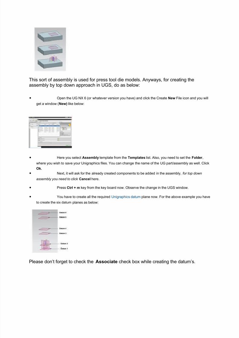
"et*s say we ha'e to create a Unigraphics assembly of three rectangular plates likebelow%
8/12/2019 Assemblies BestPractices
http://slidepdf.com/reader/full/assemblies-bestpractices 3/16
This sort of assembly is used for press tool die models. Anyways, for creating theassembly by top down approach in UG, do as below%
• +pen the UG - /or whate'er 'ersion you ha'e0 and click the Create New 1ile icon and you will
get a window /New) like below%
• 2ere you select Assembly template from the Templates list. Also, you need to set the Foler ,
where you wish to sa'e your Unigraphics files. ou can change the name of the UG part4assembly as well. Click
!"#
• e!t, it will ask for the already created components to be added in the assembly, for top down
assembly you need to click Cancel here.
• #ress Ctrl $ m key from the key board now. +bser'e the change in the UG window.
• ou ha'e to create all the re5uired Unigraphics datum plane now. 1or the abo'e e!ample you ha'e
to create the si! datum planes as below%
#lease don*t forget to check the Associate check bo! while creating the datum*s.

8/12/2019 Assemblies BestPractices
http://slidepdf.com/reader/full/assemblies-bestpractices 4/16
• ow, let*s create the first rectangular plate. Go to Assemblies → Components → Create New
Component and you will get a window similar to the New file creation window, select the %oel template and
change the name to Plate1 and click !&#
• ou will find the Create New Component window open, 6ust click !&# ou will find the 'late( has
added in the assembly naigator under the assembly.
• 7ight click the 'late( and click the ma"e wor" part#
• 7ight click the Datum( and select in" to wor" part.
• ow go to insert → !esign "eat#re → e$tr#!e and select the Datum( as sketching plane and
sketch the rectangular outline of the plate(# 1inish the sketch.
• Change the *n limits option from +alue to until selecte and select the Datum, and click o"#
ou ha'e 6ust finished modeling 'late(#
• imilarly, create the model of 'late, by taking the Datum3 as sketching plane and the Datum- for
end limit.
• Also repeat the procedure for plate3 by using Datum. and Datum/#
• a'e the file and your top down assembly is ready.
• ow, the best part, if you wish to change the thickness of the plates or the distance between them,
no need to remodeling each of the plates 6ust change the distances between the datum planes and you can see
the change.
Reference Sets allow you to control what content from a Component will be displayed in an
Assembly. Typically, you create a component part and have construction geometry, sketches,
etc. in the part that allow you to generate the solid body (or bodies) representing the actual
finished part. When you add the component to an assembly, you really only want to see thesolid body of the finished part without all the other construction ob!ects. "ou can create a
#eference $et which designates only the ob!ects you need to represent the component in the
assembly.
$ee% &ormat ' #eference $ets ' click on Add ew #eference $et ' enter a name in the
#eference $et ame window ' hit nter ' select the ob!ects which you want to include in the
#eference $et ' click close. *Why #eference sets is now under &ormat and not under
Assemblies is beyond me+.
ote% one #eference $et name we use is A$T#-/0.
When you insert the component into an assembly, you can select the #eference $et and only its
members will appear in your assembly.
Assemblies ' Components ' Add Component ' select the component part, 1lacement 2
other options (you might need to review the appropriate documentation if this is new to you) '

8/12/2019 Assemblies BestPractices
http://slidepdf.com/reader/full/assemblies-bestpractices 5/16
$ettings ' #eference $et ' select the name of the #eference $et you created in the
component part ' click on 3
Aside from standard use cases of hiding datum4s, curves, and sketches from view in an
assembly, they can also allow you to build in reference geometry to use for constructing your
assembly for e5ample, adding an ring into a specified groove may be difficult due to the
geometry of the features so adding a reference point to the ring component makes it easier to
locate it within the assembly. These types of 6reference geometry6 can be used for the
assembly while maintaining a solidonly reference set for the component model or drawing,
eliminating unwanted or unnecessary information.
Another use 7 have seen for reference sets, though it is not as typical among most 8 users
because it violates the aster odel concept, is to reference different models within the same
component for e5ample an uncompressed versus a compressed spring or ring. The two can
be modeled on different layers within the component file, and then referenced separately using
custom reference sets (such as Constrained $tate and &ree $tate). This allows a component to
be shown in either state within an assembly or other file of which it is a component (i.e. adrawing file).
2ow to find center of mass of an - assembly8
& ha'e tried )solid properties check) and )measure bodies)
Analysis (9 :easure ;odies...
...function is the way to do that. <ust make sure that the )election cope) is set to )$ntire Assembly) and
that the )Associati'e) option is toggled +. This will result in not only the creation of your typical :ass
#roperty e!pressions, but also a #oint ob6ect at the centroid of the Assembly. And if you also toggle +the )how &nformation =indow) you)ll get all of the mass property data in the listing window including the
-> coordinates of the centroid. +f course, you can also use...
&nformation (9 #oint...
...to get the -> coordinates of that )centroid) #oint ob6ect any time that you wish.
Also note that this :ass #roperty data /in the form of e!pressions0, including the )centroid) point, will
update as the Components which make up the Assembly are modified. 2owe'er, if new components are
added to the Assembly, you will need to update the ;ody :easurement feature, adding the new
Component/s0 to the measurement.
Q. I want to show the Weight (Kg) of a part in the assembly navigator window.
I know that you can assign a material and then calculate the MASS of the part; however I need to
see the actual Weight (Kg) in the column in the assembly navigator window.
Right click the part in Assembly Navigator, click Properties . Select Weight tab. Check ON "UpdateData on Save" and click "Update Weight Data Now".

8/12/2019 Assemblies BestPractices
http://slidepdf.com/reader/full/assemblies-bestpractices 6/16
Q. To Export a Pro/ENGINEER Part or
Assembly to Unigraphics
1. Set the intf3d_ug_install_dir configuration option to accurately point to theUnigraphics installation.
2. With part or assembly open, click File > Save a Copy. The Save a Copy dialog box
opens.
. Select Unigraphics File (*.prt) in the Type box. The Save a Copy dialog box
displays the existing Unigraphics file in the !orking directory.
". #ro!se to select a location for the file after export. $xisting Unigraphics .prt files in
the directory are displayed.
%. &ccept the default name !ith the extension, _ug_prt or _ug_asm that is
automatically added to the exported part or assembly name, respecti'ely, in the New
Name box or type a ne! name for the exported model.
(. )lick OK in the Save a Copy dialog box.
Note: *f you ha'e not set the intf3d_ug_install_dir configuration option to point to
the Unigraphics installation directory, a !arning in the +ro$-*-$$/ !indo! prompts
you to specify the location of the Unigraphics installation.
o The +ro$-*-$$/ file is exported to the location you ha'e specified.
o 0or an assembly, the exported component model files are named after the
corresponding +ro$-*-$$/ component model name !ith the extensions, _ug_prt
and _ug_asm, depending on the model type.
Environment ariables !or the Unigraphics
Inter!ace
ou must set the follo!ing en'ironment 'ariables before starting +ro$-*-$$/
• UGII_LICENSE_FILE 3path to the license server for the Unigraphics
installation or the node-locked license file>
• UGII_BASE_DIR 3path to the Unigraphics installation directory>
• UGII_ROOT_DIR 3path to the Unigraphics installation directory/bin> for
U-*4 and 3path to the Unigraphics installation directory/ugii> for Windo!s
The Unigraphics interface re5uires these en'ironment 'ariables to be set in addition to the
U6pen runtime license and the installation of Unigraphics either on the !orkstation on
!hich +ro$-*-$$/ is installed or accessed o'er the net!ork.
8/12/2019 Assemblies BestPractices
http://slidepdf.com/reader/full/assemblies-bestpractices 7/16
THE NX MACHINERY LIBRARY
7"2812
)lick here to see a 'ideo for this article.
*n this -4 & to 9 article * !ill discuss the -4 :achinery ;ibrary, !hich is essentially a standard parts
library that can be do!nloaded from Siemens by any acti'e -4 customer. * !ill explain ho! to
do!nload and install it, ho! to share it !ith all of the -4 users in your company and ho! to add the
standard parts to your -4 assemblies.
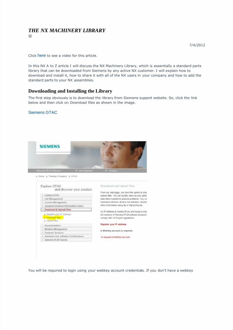
Downloading and Installing the Library
The first step ob'iously is to do!nload the library from Siemens support !ebsite. So, click the link
belo! and then click on Download files as sho!n in the image.
$iemens 9TAC
ou !ill be re5uired to login using your !ebkey account credentials. *f you don<t ha'e a !ebkey
8/12/2019 Assemblies BestPractices
http://slidepdf.com/reader/full/assemblies-bestpractices 8/16
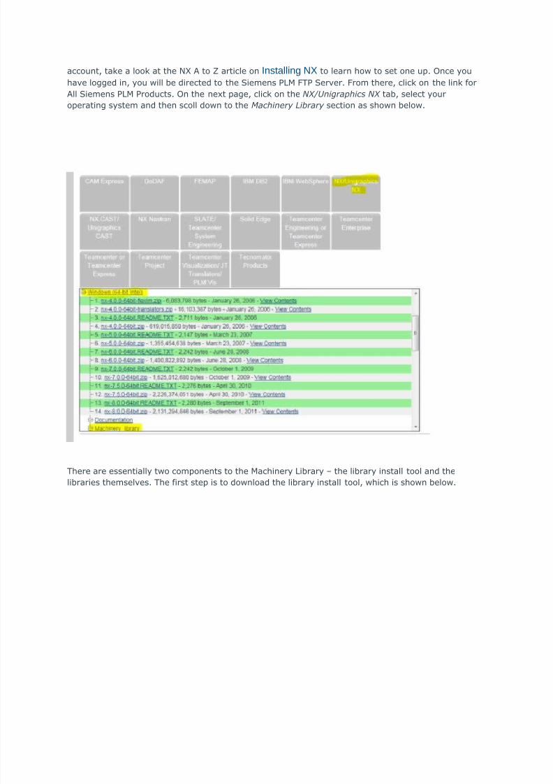
account, take a look at the -4 & to 9 article on 7nstalling 8 to learn ho! to set one up. 6nce you
ha'e logged in, you !ill be directed to the Siemens +;: 0T+ Ser'er. 0rom there, click on the link for
&ll Siemens +;: +roducts. 6n the next page, click on the NX/Unigraphics NX tab, select your
operating system and then scoll do!n to the Machinery Library section as sho!n belo!.
There are essentially t!o components to the :achinery ;ibrary = the library install tool and the
libraries themsel'es. The first step is to do!nload the library install tool, !hich is sho!n belo!.

8/12/2019 Assemblies BestPractices
http://slidepdf.com/reader/full/assemblies-bestpractices 9/16
6nce you ha'e that do!nloaded, then you can do!nload as many libraries as you !ant. *t is best to
select the ne!est 'ersion of each library and you need to be using -4 % or later to use the machinery
library. ou can do!nload the install tool and the libraries to any location on your computer or your
net!ork. ou should also do!nload Machinery-Library-readme.doc explains ho! to start the install
tool?.
6ne you ha'e the install tool and the libraries that you !ant do!nloaded, un@ip the install tool = don<t
un@ip the libraries = and then open the NX_Machiery Library Install - User !ide folder and in this
folder are the install instructions. Which basically consist of the putting the @ipped up libraries in the
NX_Machinery Library Install - "its#tool#libs folder and then running MachineryLibrary-Installation.bat .
The only thing to be a!are of is that if you !ant e'eryone at your company that is using -4 to access
the same instance of the library makes updates easier and makes any customi@ations a'ailable to
e'eryone? then you need to install the library on your net!ork, not on your local hard dri'e.
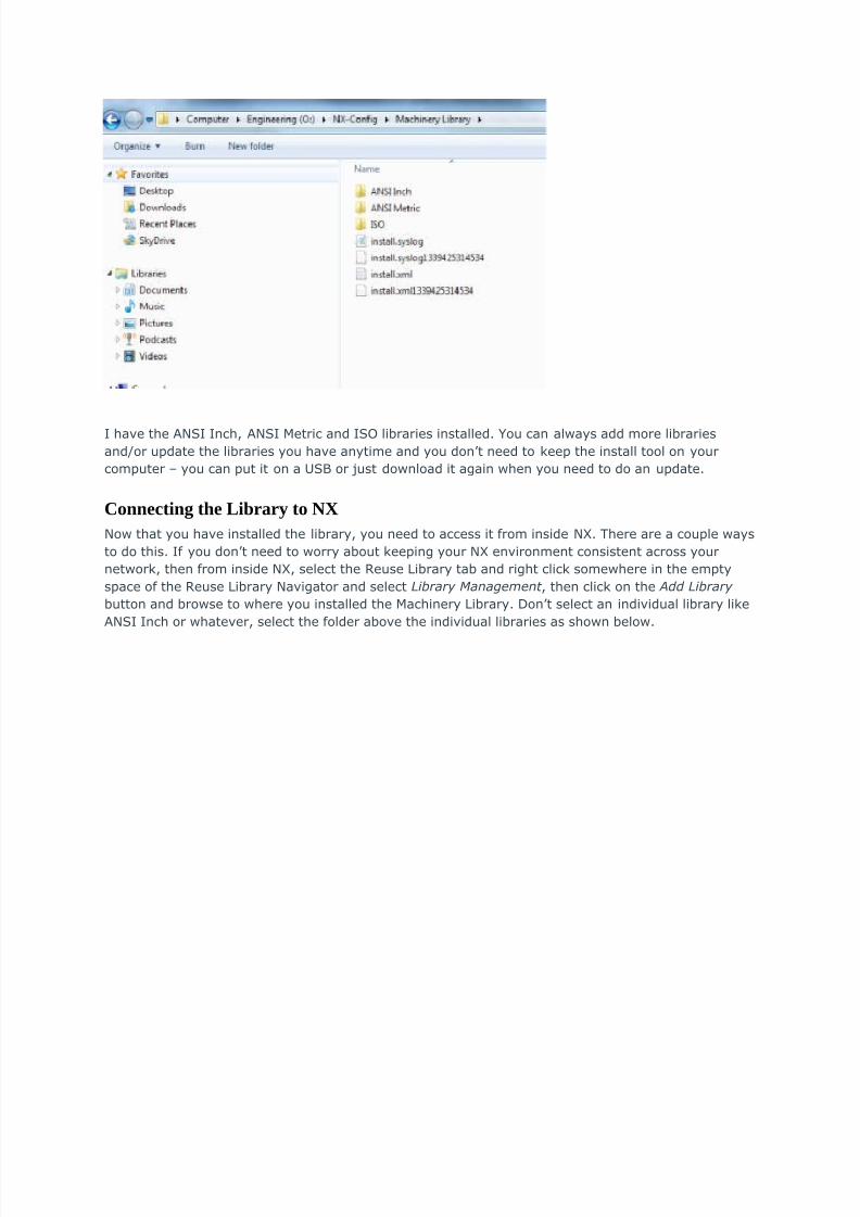
6nce you ha'e installed the library, you should ha'e a folder like this !here'er you elected to install
it.
8/12/2019 Assemblies BestPractices
http://slidepdf.com/reader/full/assemblies-bestpractices 10/16
* ha'e the &-S* *nch, &-S* :etric and *S6 libraries installed. ou can al!ays add more libraries
andor update the libraries you ha'e anytime and you don<t need to keep the install tool on your
computer = you can put it on a US# or Aust do!nload it again !hen you need to do an update.
Connecting the Library to NX
-o! that you ha'e installed the library, you need to access it from inside -4. There are a couple !ays
to do this. *f you don<t need to !orry about keeping your -4 en'ironment consistent across your
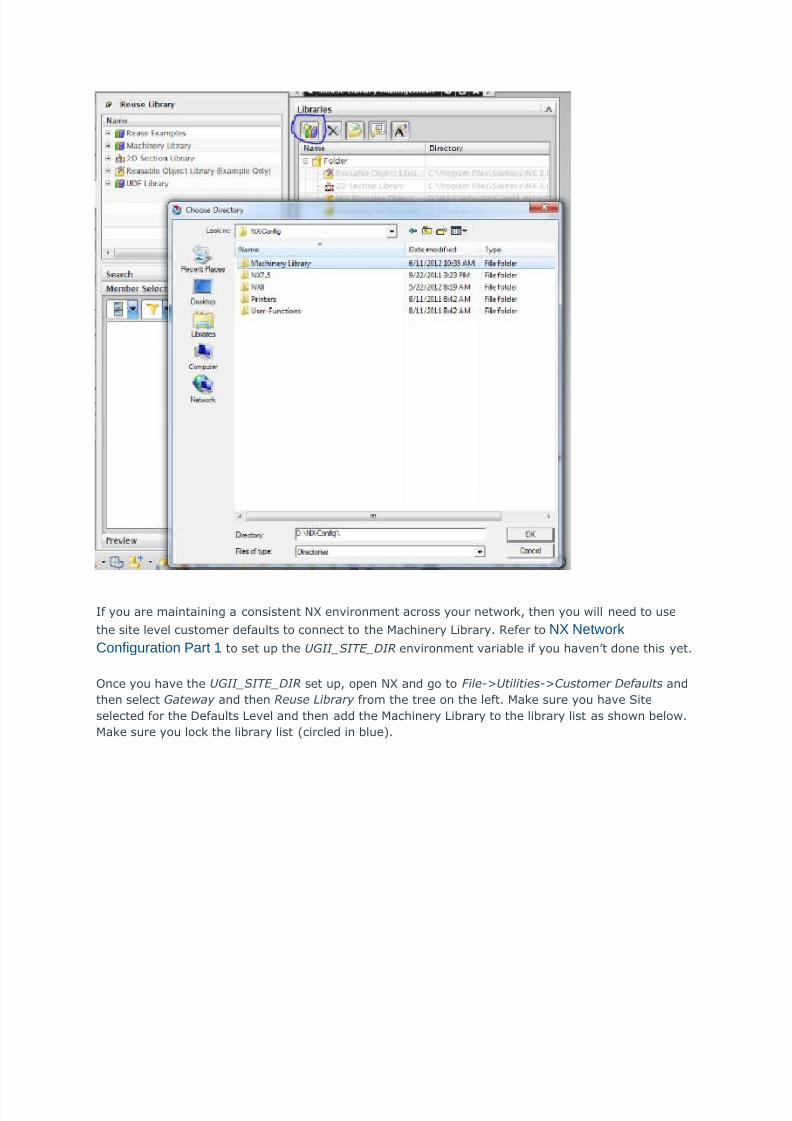
net!ork, then from inside -4, select the /euse ;ibrary tab and right click some!here in the empty
space of the /euse ;ibrary -a'igator and select Library Management , then click on the $dd Library
button and bro!se to !here you installed the :achinery ;ibrary. Bon<t select an indi'idual library like
&-S* *nch or !hate'er, select the folder abo'e the indi'idual libraries as sho!n belo!.
8/12/2019 Assemblies BestPractices
http://slidepdf.com/reader/full/assemblies-bestpractices 11/16
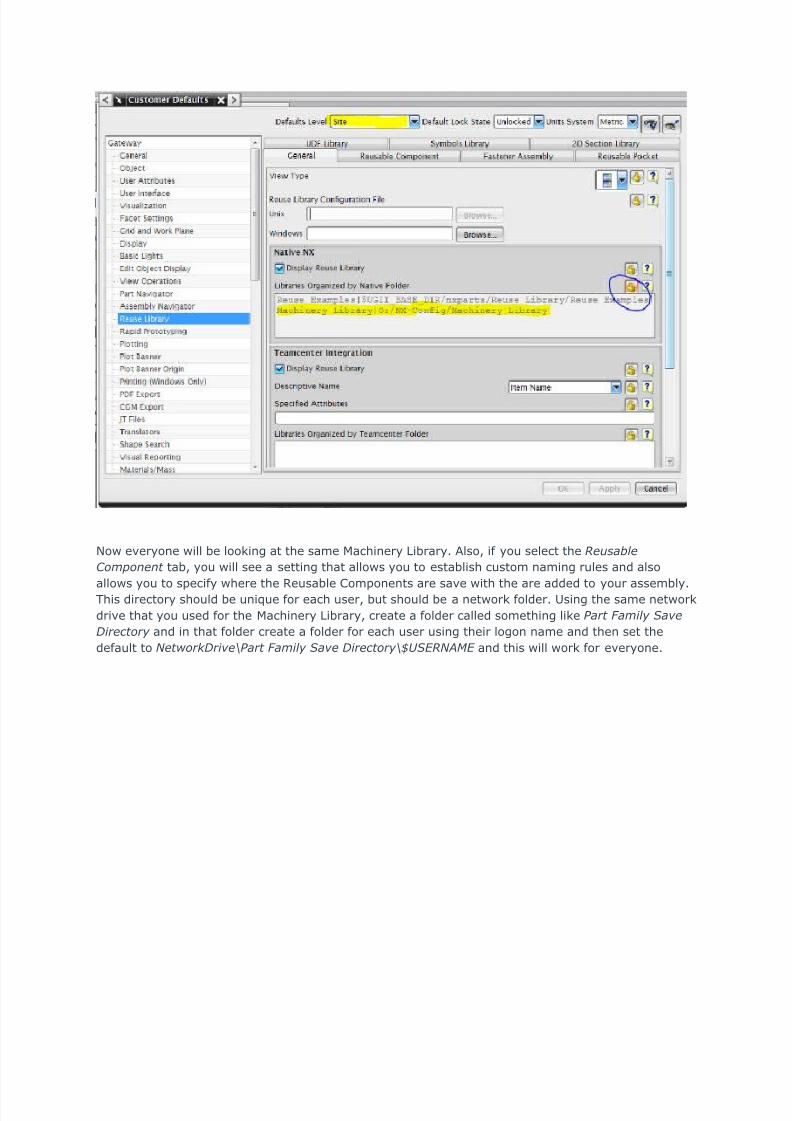
*f you are maintaining a consistent -4 en'ironment across your net!ork, then you !ill need to use
the site le'el customer defaults to connect to the :achinery ;ibrary. /efer to 8 etwork
Configuration 1art : to set up the UII_%I&'_DI( en'ironment 'ariable if you ha'en<t done this yet.
6nce you ha'e the UII_%I&'_DI( set up, open -4 and go to )ile-*Utilities-*+!stomer Defa!lts and
then select ateway and then (e!se Library from the tree on the left. :ake sure you ha'e Site
selected for the Befaults ;e'el and then add the :achinery ;ibrary to the library list as sho!n belo!.
:ake sure you lock the library list circled in blue?.
8/12/2019 Assemblies BestPractices
http://slidepdf.com/reader/full/assemblies-bestpractices 12/16
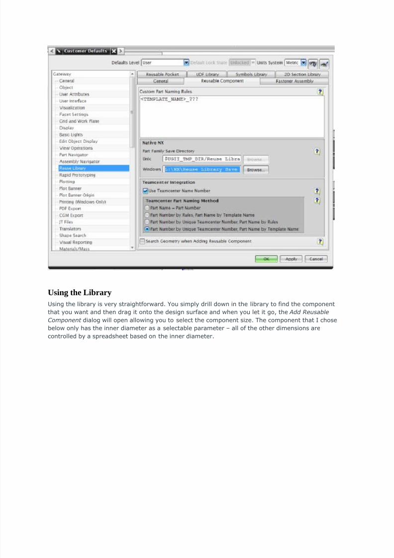
-o! e'eryone !ill be looking at the same :achinery ;ibrary. &lso, if you select the (e!sable
+omponent tab, you !ill see a setting that allo!s you to establish custom naming rules and also
allo!s you to specify !here the /eusable )omponents are sa'e !ith the are added to your assembly.This directory should be uni5ue for each user, but should be a net!ork folder. Using the same net!ork
dri'e that you used for the :achinery ;ibrary, create a folder called something like ,art )amily %ae
Directory and in that folder create a folder for each user using their logon name and then set the
default to Networ"Drie#,art )amily %ae Directory#U%'(N$M' and this !ill !ork for e'eryone.
8/12/2019 Assemblies BestPractices
http://slidepdf.com/reader/full/assemblies-bestpractices 13/16
Using the LibraryUsing the library is 'ery straightfor!ard. ou simply drill do!n in the library to find the component
that you !ant and then drag it onto the design surface and !hen you let it go, the $dd (e!sable
+omponent dialog !ill open allo!ing you to select the component si@e. The component that * chose
belo! only has the inner diameter as a selectable parameter = all of the other dimensions are
controlled by a spreadsheet based on the inner diameter.
8/12/2019 Assemblies BestPractices
http://slidepdf.com/reader/full/assemblies-bestpractices 14/16
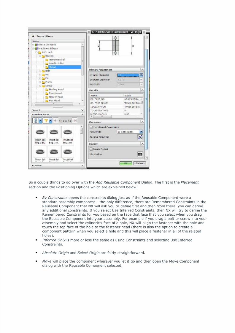
So a couple things to go o'er !ith the $dd (e!sable +omponent Bialog. The first is the ,lacement
section and the +ositioning 6ptions !hich are explained belo!
y +onstraints opens the constraints dialog Aust as if the /eusable )omponent !ere a
standard assembly component = the only difference, there are /emembered )onstraints in the/eusable )omponent that -4 !ill ask you to define first and then from there, you can defineany additional constraints. *f you select Use *nferred )onstraints, then -4 !ill try to define the/emembered )onstraints for you based on the face that face that you select !hen you dragthe /eusable )omponent into your assembly. 0or example if you drag a bolt or scre! into yourassembly and select the cylindrical face of a hole, -4 !ill align the fastener !ith the hole andtouch the top face of the hole to the fastener head there is also the option to create acomponent pattern !hen you select a hole and this !ill place a fastener in all of the relatedholes?.
Inferred 0nly is more or less the same as using )onstraints and selecting Use *nferred)onstraints.
$bsol!te 0rigin and %elect 0rigin are fairly straightfor!ard.
Moe !ill place the component !here'er you let it go and then open the :o'e )omponentdialog !ith the /eusable )omponent selected.
8/12/2019 Assemblies BestPractices
http://slidepdf.com/reader/full/assemblies-bestpractices 15/16
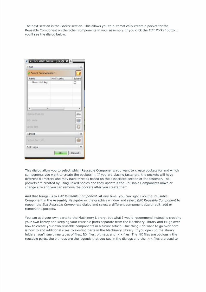
The next section is the ,oc"et section. This allo!s you to automatically create a pocket for the
/eusable )omponent on the other components in your assembly. *f you click the 'dit ,oc"et button,
you<ll see the dialog belo!.
This dialog allo! you to select !hich /eusable )omponents you !ant to create pockets for and !hich
components you !ant to create the pockets in. *f you are placing fasteners, the pockets !ill ha'e
different diameters and may ha'e threads based on the associated section of the fastener. The
pockets are created by using linked bodies and they update if the /eusable )omponents mo'e or
change si@e and you can remo'e the pockets after you create them.
&nd that brings us to 'dit (e!sable +omponent . &t any time, you can right click the /eusable
)omponent in the &ssembly -a'igator or the graphics !indo! and select 'dit (e!sable +omponent to
reopen the 'dit (e!sable +omponent dialog and select a different component si@e or edit, add orremo'e the pockets.
ou can add your o!n parts to the :achinery ;ibrary, but !hat * !ould recommend instead is creating
your o!n library and keeping your reusable parts separate from the :achinery ;ibrary and *<ll go o'er
ho! to create your o!n reusable components in a future article. 6ne thing * do !ant to go o'er here
is ho! to add additional si@es to existing parts in the :achinery ;ibrary. *f you open up the library
folders, you<ll see three types of files, -4 files, bitmaps and .krx files. The -4 files are ob'iously the
reusable parts, the bitmaps are the legends that you see in the dialogs and the .krx files are used to
8/12/2019 Assemblies BestPractices
http://slidepdf.com/reader/full/assemblies-bestpractices 16/16
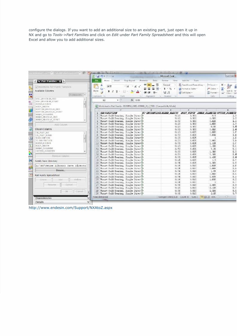
configure the dialogs. *f you !ant to add an additional si@e to an existing part, Aust open it up in
-4 and go to &ools-*,art )amilies and click on 'dit under ,art )amily %preadsheet and this !ill open
$xcel and allo! you to add additional si@es.
http!!!.endesin.comSupport-4&to9.aspx