assembly & operation manual - blizzard plows
TRANSCRIPT

Assembly & Operation ManualBlizzard Straight Blade Snowplows
Models 760LD, 760 & 800
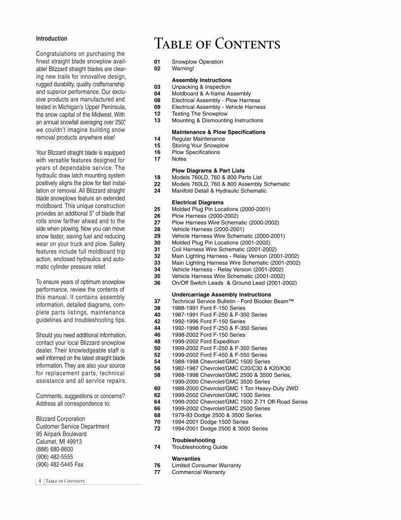
i Table of Contents
Introduction
Congratulations on purchasing the finest straight blade snowplow avail-able! Blizzard straight blades are clear-ing new trails for innovative design,rugged durability, quality craftsmanshipand superior performance. Our exclu-sive products are manufactured andtested in Michigan’s Upper Peninsula,the snow capital of the Midwest. Withan annual snowfall averaging over 250,"we couldn’t imagine building snowremoval products anywhere else!
Your Blizzard straight blade is equippedwith versatile features designed foryears of dependable service. Thehydraulic draw latch mounting systempositively aligns the plow for fast instal-lation or removal. All Blizzard straightblade snowplows feature an extendedmoldboard. This unique constructionprovides an additional 5" of blade that rolls snow farther ahead and to the side when plowing. Now you can movesnow faster, saving fuel and reducingwear on your truck and plow. Safetyfeatures include full moldboard tripaction, enclosed hydraulics and auto-matic cylinder pressure relief.
To ensure years of optimum snowplow performance, review the contents of this manual. It contains assembly information, detailed diagrams, com-plete par ts listings, maintenanceguidelines and troubleshooting tips.
Should you need additional information,contact your local Blizzard snowplowdealer. Their knowledgeable staff is well informed on the latest straight bladeinformation. They are also your sourcefor replacement par ts, technicalassistance and all service repairs.
Comments, suggestions or concerns?Address all correspondence to:
Blizzard CorporationCustomer Service Department95 Airpark BoulevardCalumet, MI 49913(888) 680-8600(906) 482-5555(906) 482-5445 Fax
Table of Contents01 Snowplow Operation02 Warning!
Assembly Instructions03 Unpacking & Inspection04 Moldboard & A-frame Assembly08 Electrical Assembly - Plow Harness09 Electrical Assembly - Vehicle Harness12 Testing The Snowplow13 Mounting & Dismounting Instructions
Maintenance & Plow Specifications14 Regular Maintenance15 Storing Your Snowplow16 Plow Specifications17 Notes
Plow Diagrams & Part Lists18 Models 760LD, 760 & 800 Parts List22 Models 760LD, 760 & 800 Assembly Schematic24 Manifold Detail & Hydraulic Schematic
Electrical Diagrams25 Molded Plug Pin Locations (2000-2001)26 Plow Harness (2000-2002)27 Plow Harness Wire Schematic (2000-2002)28 Vehicle Harness (2000-2001)29 Vehicle Harness Wire Schematic (2000-2001)30 Molded Plug Pin Locations (2001-2002)31 Coil Harness Wire Schematic (2001-2002)32 Main Lighting Harness - Relay Version (2001-2002)33 Main Lighting Harness Wire Schematic (2001-2002)34 Vehicle Harness - Relay Version (2001-2002)35 Vehicle Harness Wire Schematic (2001-2002)36 On/Off Switch Leads & Ground Lead (2001-2002)
Undercarriage Assembly Instructions37 Technical Service Bulletin - Ford Blocker Beam™38 1988-1991 Ford F-150 Series40 1987-1991 Ford F-250 & F-350 Series42 1992-1996 Ford F-150 Series44 1992-1998 Ford F-250 & F-350 Series46 1998-2002 Ford F-150 Series48 1999-2002 Ford Expedition50 1999-2002 Ford F-250 & F-350 Series52 1999-2002 Ford F-450 & F-550 Series54 1988-1998 Chevrolet/GMC 1500 Series56 1982-1987 Chevrolet/GMC C20/C30 & K20/K3058 1988-1998 Chevrolet/GMC 2500 & 3500 Series,
1999-2000 Chevrolet/GMC 3500 Series60 1988-2000 Chevrolet/GMC 1 Ton Heavy-Duty 2WD62 1999-2002 Chevrolet/GMC 1500 Series64 1999-2002 Chevrolet/GMC 1500 Z-71 Off-Road Series 66 1999-2002 Chevrolet/GMC 2500 Series68 1979-93 Dodge 2500 & 3500 Series70 1994-2001 Dodge 1500 Series72 1994-2001 Dodge 2500 & 3500 Series
Troubleshooting74 Troubleshooting Guide
Warranties76 Limited Consumer Warranty77 Commercial Warranty

Snowplow Operation 01
Snowplow OperationYour snowplow is the most advanced and versatile straight blade on the market.The easy-to-use joystick control allows you to automatically adjust the plowblade into an infinite number of plowing positions. Review the illustrationsbelow for instruction on maneuvering your snowplow.
A.
B.
C.
D.
A. Lowered or Float Position
Pushing the joystick forward, toward the “Lower/Float” designation on the label, will lower yourstraight blade to the ground. Pushing the joystickahead until the detent “locks” the control will allowthe snowplow to “float”, or follow the contour ofthe ground when moving forward or backward.
B. Raised Position
Pulling the joystick back, toward the “Raise”designation on the label, will lift your straightblade off of the ground. To stop raising the plow,simply return the joystick to its “neutral” or centerposition. The snowplow has reached its maximumraised position when the blade stops lifting –return the joystick to its neutral position.
C. Angled Right Position
To angle your straight blade to the right, positionthe joystick toward the “R” on the label. To stopangling the plow, return the joystick to its “neutral”or center position. The snowplow has reached itsmaximum angled position when the blade stopsmoving to either side.
D. Angled Left Position
To angle your straight blade to the left, positionthe joystick toward the “L” on the label. To stopangling the plow, return the joystick to its “neutral”or center position. The snowplow has reached itsmaximum angled position when the blade stopsmoving to either side.
BLIZZARD
To prevent accidental plow activation, turnPOWER switch to the “OFF” position whennot in use. BLZ 1017
WARNING
®

02 Warning!
Warning!
Prior to operating your straight blade, review the WARNING! label at the passenger’s side rear of the moldboard (shown below).
Note: Read and understand all warnings indicated in this manual prior tooperating the snowplow. Warnings and cautions in the manual are indicatedby the icons shown to the left.
WARNING:
CAUTION:
1. Verify the main power switch on the control unit is in the “OFF” position when the snowplow is not in use.
2. Properly mount the snowplow prior to moving the vehicle.
3. Stand clear of the attachment area when mounting the snowplow to the undercarriageand operating the Power Hitch Connect/Disconnect switch. Failure to do so mayresult in serious injury or death.
4. Securely position all mounting pins prior to operating your snowplow.
5. Do not position your body between the snowplow and the vehicle when servicingor operating.
6. Position snowplow in such a manner as to not block your vision or plow headlightswhile in transit.
7. Do not change the position of the blade while in transit.
8. Do not exceed 40 mph when transporting plow.
9. Do not exceed 10 mph when plowing.
10. Always lower blade when vehicle is parked.
11. Vehicles equipped with air bags are designed to be activated in a frontal collisionequivalent to hitting a solid object or barrier at approximately 14 mph or more.
Careless or high speed driving while plowing snow, which results in vehicle impactdeceleration equivalent to or greater than the airbag deployment threshold describedabove, would deploy the airbag.
Models 760 and 800 Blizzard snowplows have United States patents pending.
READOWNER’SMANUAL
THOROUGHLYPRIOR TO
OPERATINGPLOW.
Calumet, Michigan 49913
BLZ 1024
WARNING
WARNING
Should the WARNING! label or any of the labelsthat came with your snowplow become hard toread or wear off, contact your local dealer or callour Customer Service Department toll free at 1-888-680-8600 for replacements.

Assem. Instructions - Unpacking & Inspection 03
Assembly Instructions
Unpacking & Inspection
Your Blizzard straight blade has been packaged to withstand transit andweather related damage. Fully inspect all components upon receipt of your plow.In the event of shipping damage or missing parts, immediately contact ourCustomer Service Department toll free at 1-888-680-8600.
Begin unpacking and inspection in the following order:
1. Remove packaging slip from the end panel of the pallet wrap. Retainall documentation for your records.
2. All wood framing and polyethylene material should be removed from thepallet for easy access to the snowplow.
3. Due to the odd shaped components and size of several assembly parts,various nylon ties and corrugates are used for scratch resistance andpackage orientation. Please remove these items prior to assembly.
4. Place the main blade assembly on a flat, level surface.
Once you have inspected all parts and removed all restraining and protectivepackaging materials, your snowplow is ready to be fully assembled.
Pallet Wrap End Panel
The tear resistant woven polyethylene palletwrap contains a moisture barrier to help protectall packaged components and keep out the mostinclement weather during shipping and storage.The end panel of the pallet cover containsimportant information regarding the make, model,and year of the vehicle the enclosed undercar-riage is to be installed on. The plow model numberand the serial number of the snowplow are giventogether. The first three digits and/or two letters in the the number indicated is always the plowmodel – 800 or 760LD – and the entire seven(nine) digit number make up the serial number.The packaging list is also attached to the endpanel. Be sure to retain this list for your records.

04 Assem. Instructions - Moldboard & A-frame
Moldboard & A-Frame Assembly
1. Begin the moldboard assembly by positioning the PIVOT BEAM and A-FRAME near the connecting points at the rear of the blade betweenthe two center support ribs. Position the pivot beam between the two support ribs until the connecting points on the beam align with those onthe plow. Insert one 3/4"-10 x 3-1/2" hex head screw through each mountinghole and secure with a 3/4"-10 top lock nut. Tighten each nut until it issnug with the pivot beam.
CAUTION: Do not over tighten hex head nuts! Binding mayprohibit the pivot beam from moving properly on the plow.
Note: To aid in the remaining installation, rotate the spring loaded kick-stand clockwise until it locks into place. Adjust the foot on the kickstandarm so the height of the A-frame, at its mount points, is 12-1/2" to levelground (See diagram on page 7). Tighten both of the 1/2"-13 top lock nutson the kickstand.
2. Position each ANGLE CYLINDER with the rod end of the cylinder in thepivot beam and the hydraulic hose port facing away from the A-frame.Secure the cylinder to the pivot beam with one 3/4"-10 x 5" (3/4"-10 x 4-1/2" for 760LD only) hex cap screw and one 3/4"-10 top lock nut. Extendeach cylinder rod until the cylinder base mounting hole aligns with thehole on the A-frame angle cylinder bracket. At this point, insert one3/4"-10 x 5" (3/4"-10 x 4-1/2") hex cap screw through the aligned holesand secure the screw with one 3/4" top lock nut. Repeat the same instal-lation for the opposite angle cylinder.
3. Remove each dust cap from both of the hydraulic angle cylinder portsand attach one 9/16"-18 x 9/16"-18 90˚ ADJUSTABLE ELBOW O.R.B.ADAPTER to each port. Note: All of the hydraulic adapters can be foundpackaged with the manifold assembly. Hand tighten each adapter untilsnug, then torque approximately 1-1/2 to 2-1/2 flats. Reference the tableon page 5 for proper torque specifications. Angle each adapter towardthe top of the moldboard and tighten approximately 1-1/2 flats. Connectthe 3/8" x 24" hydraulic hose, labeled #1, to the driver’s side angle cylinderadapter. Attach the 3/8" x 24" hydraulic hose, identified by a #2, to thepassenger’s side angle cylinder adapter. Be careful not to overtighten thehose connections. Route both hoses over the top of each angle cylinder.
4. Next, remove both of the plastic dust caps from the HYDRAULIC LIFTCYLINDER ports. Attach one 7/16"-20 x 7/16"-20 45˚ ADJUSTABLEELBOW O.R.B. ADAPTER to the driver’s side port and one 7/16"-20 x7/16"-20 MALE O.R.B. CONNECTOR ADAPTER to the passenger’s sideport. Once the adapters have been installed on the cylinder, connect theHYDRAULIC HOSES. The 45˚ adapter on the driver’s side of the cylinderreceives a 1/4" x 17" hose identified by a label containing the number 3.Connect the 45˚ angle on the hose to the hydraulic adapter on the cylinder.The male connector adapter on the passenger’s side of the cylinderreceives a 1/4" x 15" hose identified by a label containing the number 4.Tighten the 45˚ end of the hose to the hydraulic adapter on the cylinder.Both hoses should be routed through the triangular openings in the A-frame.
5. Next, use a screwdriver to pull the hydraulic cylinder rod out from itsbase. Place one 1-1/4" (1", 2" O.D. for 760LD only) diameter washer overthe cylinder rod, followed by the 12" COMPRESSION SPRING and another1-1/4" (1", 2-1/4" O.D. for 760LD only) washer. Compress the coils approx-
Maximum Bolt Torque(Dry Conditions Only)
Diameter-Thread Pitch Grade 8 (foot-pounds)
1/4"-20 11 ft-lbs5/16"-18 24 ft-lbs
3/8"-16 44 ft-lbs7/16"-14 70 ft-lbsM12 x1.75 88 ft-lbs
1/2"-13 107 ft-lbsM14 x 2.0 140 ft-lbs
9/16"-12 154 ft-lbs5/8"-11 211 ft-lbs3/4"-10 376 ft-lbs
1"-08 900 ft-lbs
Note: Use 25% less torque when lubricated.Check and re-tighten all fasteners after thefirst three hours of use. Periodically reviewall fasteners after the initial inspection.
7/16" 7/16"
Male O.R.B. Connector Adapter
7/16"
7/16"
45˚ Adjust. Elbow O.R.B. Adapter
9/16"
9/16"
90˚ Adjust. Elbow O.R.B. Adapter

Assem. Instructions - Moldboard & A-frame 05
A-FrameLatch Pull Pin
A-FrameLatch
Outer DrawLatch Plate
Inner DrawLatch Plate
HydraulicLift / LowerCylinder
1/4"-20 x 1/2"Set Screw
6" ExtensionSpring
1/2"-13 x 2" Bolt
Inner DrawLatch PlateCylinderMount Pin(3/4"x 2-1/2")(5/8"x 2-3/8") for760LD only
Draw Latch BoltMount Pin (1"x 6") or(1"x 5-5/8") for 760LD only
Draw LatchMount Pin(1"x 4-1/2") or(1"x 3-7/8") for760LD only
3/4"-10 x 4-1/2" Boltor 3/4"-10 x 4"for LD only
3/8"-16 x 3/4" Bolt
imately 2" and clamp the spring and washers in place using a pair of visegrips. This will help facilitate the draw latch installation.
6. Begin the draw latch installation by first removing both of the 6" extensionsprings on the latch. Proceed to remove both 1/2"-13 x 2" bolts withwashers and spacers from the DRAW LATCH BOLT MOUNT PIN. Oncethe springs and hardware have been removed, loosen the SET SCREWon the OUTER DRAW LATCH PLATE using a 1/8" Allen wrench andremove the draw latch bolt mount pin from the assembly.
Next, remove the 1" x 4-1/2" (1" x 3-7/8" for 760LD only) DRAW LATCHMOUNT PIN from the assembly. By removing this pin, the INNER DRAWLATCH PLATES can swing free. Proceed to remove the 3/4" x 2-1/2"(5/8" x 2-3/8" for 760LD only) INNER DRAW LATCH PLATE CYLINDERMOUNT PIN. Position the plates on either side of the lift/lower cylinder rodand insert the 3/4" x 2-1/2" (5/8" x 2-3/8") pin through the plates and cylinder rod. Note: The A-FRAME LATCH, located at the rear center of theA-frame, should be in the down position. Pull the A-FRAME LATCH PULLPIN out and rotate the latch clockwise if it is in the raised position. Nowthat the cylinder is connected to the inner draw latch plates, rotate the drawlatch assembly toward the draw latch mount holes on the A-frame. Alignthe holes in the outer draw latch plate with those of the inner draw latchplates and the A-frame. Secure the assembly to the A-frame by replacingthe draw latch mount pin. Remove the vise grips from the cylinder rod.This will allow the compression spring to expand against the draw latch.
Rotate the A-frame latch counterclockwise until the A-frame latch pull pinlocks into place. Next, replace the draw latch bolt mount pin. The pinshould be evenly spaced on either side of the outer draw latch plates.Tighten the set screw to secure the pin in place. Complete the draw latchassembly by replacing the washers, spacers, extension springs and boltson both sides of the draw latch bolt mount pin.
Draw Latch Assembly
The draw latch consists of a series of intercon-nected plates and pins that attach to the A-frameand the hydraulic cylinder that raises and lowersthe plow. The draw latch is also the most difficultcomponent to install on the entire plow and mayrequire the help of a second technician.
OneFlat
TwoFlats
Torque Table for 37˚AdaptersPort
Thread Size
AssemblyTorque
(foot-pounds)
Original Assembly
(F.F.F.T.)
7/16-20 15 ± 1.0 2.5 ±.259/16-18 18 ± 2.0 2.5 ±.25
Torque Table for O.R.B. AdaptersPort
Thread Size
AssemblyTorque
(foot-pounds)
Original Assembly
(F.F.F.T.)
7/16-20 15 ± 1.0 1.5 ±.259/16-18 25 ± 2.0 1.5 ±.25
F.F.F.T. = Flats From Finger Tight
Ex.) After threading a 7/16-20 O.R.B. adapterfinger tight, torque the fitting approximately 1-1/2 flats (faces) for proper installation.
A-FrameLatchLock Pin
SpringMount
A-FrameLatch
To mount the straight blade, the A-frame latchshould be lowered over the spring mount – thisallows the draw latch to pull the plow into theundercarriage. Once the plow is safely attachedto the undercarriage, rotate the A-frame latchcounterclockwise until the lock pin snaps in place.The A-frame latch is only used to mount the plow.
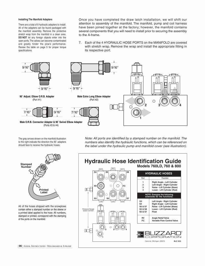
Once you have completed the draw latch installation, we will shift our attention to assembly of the manifold. The manifold, pump and coil harnesshave been joined together at the factory; however, the manifold contains several components that you will need to install prior to securing the assemblyto the A-frame.
7. Each of the 4 HYDRAULIC HOSE PORTS on the MANIFOLD are coveredwith stretch wrap. Remove the wrap and install the appropriate fitting inits respective port.
Note: All ports are identified by a stamped number on the manifold. Thenumbers also identify the hydraulic functions, which can be referenced onthe label under the hydraulic pump and manifold cover (see illustration).
06 Assem. Instructions - Moldboard & A-frame
Installing The Manifold Adapters
There are a total of 6 hydraulic adapters to install.All of the adapters can be found packaged withthe manifold assembly. Remove the protectivestretch wrap from the manifold in a clean area.DO NOT let any foreign objects enter into theopen ports. The valves can become contaminatedand greatly hinder the plow’s performance.Review the table on page 5 for proper torquespecifications.
The gray arrows shown on the manifold illustrationto the right indicate the direction the 90˚ adaptersshould face to receive the hydraulic hoses.
7/16" 9/16" 7/16"
9/16"
9/16" 9/16"
9/16"
Male O.R.B. Connector Adapter & 90˚ Swivel Elbow Adapter(Ports #3 & #4)
90˚ Adjust. Elbow O.R.B. Adapter(Port #1)
Male Extra Long Elbow Adapter(Port #2)
StampedNumber
PrintedLabel
All of the hoses shipped with the snowplowscontain either a stamped number on the sleeve ora printed label applied to the hose. All numbers,stamped or printed, correspond with the stampingof the ports on the manifold.

Assem. Instructions - Moldboard & A-frame 07
8. Next, align the mount holes in the pump with the holes in the hingedbracket, located on the A-frame. Note: To help facilitate the pump mount,first angle the hinged bracket as needed and tighten the bracket hardware,locking it in place.
CAUTION: When installing the manifold between the mountbrackets on the A-frame, hold the manifold at the sides of theblock. Never handle the manifold by the wire lead coils. Doingso can cause a solenoid cartridge to bend, causing the cartridgeto stick when activated.
Secure one 3/8"-16 x 3/4" hex cap screw and 3/8" flat washer through thetop mount hole in the bracket and into the pump. Insert one 3/8"-16 x 1-1/2"threaded stud and jam nylon insert lock nut through the bottom mounthole in the bracket and into the pump. The threaded stud should bottomout in the pump.
9. Once the pump and manifold assembly is in place, connect the hydraulichoses to their respective adapters on the manifold. Remember, the labelingon the hydraulic hoses correspond with the stamped numbers on themanifold.
Begin installing the hoses with the driver’s side raise cylinder hose (#3).Attach the straight end of the hose to the 7/16"-20 x 9/16"-18 90˚ swivelelbow adapter on the manifold. Connect the passenger’s side lower cylinderhose to Port #4. Loop the hose through the opening in the A-frame andconnect the straight end of the hose to the 7/16"-20 90˚ swivel elbow adapter.Run both angle cylinder hoses (#1 and #2) over the A-frame angle andto their respective manifold ports. Note: The lift cylinder hoses should berouted through the triangular openings in the A-frame.
10. Next, secure the manifold to the A-frame. Remove both 3/8" flat washers,3/8" split lock washers and 3/8"-16 x 1" hex cap screws from the manifoldand align the mount holes with the A-frame brackets. Position the DIODEPACK MOUNT BRACKET against the outside of the A-frame bracket onthe driver’s side. Note: Both of the prongs should be facing up. Align the outside hole on the diode bracket with the holes on the A-frame and manifold. Properly replace and tighten all hardware.
11. Hook each EXTENSION SPRING to the 3/4" diameter receiving holeslocated on the pivot beam and connect the opposite end of the spring totheir respective SPADE BOLTS. Install the four 5/8"-11 x 6-11/16" (three5/8"-11 x 5" for 760LD only) spade bolts through the EXTENSION SPRINGMOUNTING ANGLE on the top rear of the blade. Secure each spade boltby placing one 5/8" flat washer on the bolt and thread one 5/8"-11 nyloninsert lock nut. Tighten each lock nut until light appears between the coilsof the spring.
12. Install the flexible BLADE GUIDES at each end of the moldboard. Insertthe 5/16"-18 x 1" hex head screw through the holes provided at the topof the outside reinforcement rib. Tighten all screws using the nylon insertlock nuts provided.
Congratulations! You have successfully completed half of the installation.Don’t quit now! You’re nearly out of the garage.
When installing the manifold between the mountbrackets on the A-frame, DO NOT handle themanifold by the wire lead coils. The solenoid cartridges can bend, causing them to stick whenactivated. Always carry the manifold by the sidesof the aluminum block.
The kickstand is mounted to the side of the pivotbeam with one 1/2"-13 x 4-1/2" hex cap screwand top lock nut. To pivot the kickstand, simplypull the spring loaded leg out and rotate it untilthe pin locks into place. The kickstand also hasan adjustable foot that can be moved to accom-modate varying vehicle heights. The properheight of your snowplow mounting points to levelground should be set at 12-1/2".
Spring LoadedAdjustablePivot BeamKickstand
12-1/2"

08 Assembly Instructions - Plow Harness
Electrical Assembly - Plow Harness
1. Begin the installation by connecting the RED POWER WIRE to the PUMPmotor terminal using the hardware provided on the pump.
2. Place one 3/8" TOOTH LOCK WASHER, BLACK GROUND WIRE fromthe PLOW ELECTRICAL HARNESS and the RED GROUND WIRE onthe COIL WIRE LEAD HARNESS, from the manifold, to the 3/8"-16 x 1"welded ground bolt on the A-frame. Secure both grounds to the A-framewith a 3/8"-16 top lock nut. Note: If your plow only has a hole in the passenger’s side A-frame angle, a 3/8"-16 x 1" bolt, nut and 3/8" toothlock washer can be found in the packaged hardware kit.
3. Remove the hex jam nut and external tooth lock washer from the POWERHITCH CONNECT/DISCONNECT TOGGLE SWITCH and insert it throughthe back of the mounting bracket on the A-frame. Align the notch in thekey washer on the switch to the notch on the bracket. Replace the lockwasher and jam nut and tighten until the switch is firmly in place. Next,attach the connector on the plow harness to the switch. Note: Use cautionwhen making the connection. Switches can break if done forcefully.
4. Continue the harness installation by connecting the FEMALE ELECTRICCONNECTOR on the harness to the MALE ELECTRIC CONNECTORfound on the coil wire lead harness attached to the manifold. Note: If the plow harness you received contains a separate coil ground wire harness,disregard this part (see illustration to the left). The coils on the manifoldare grounded to the A-frame. See step number two above.
5. Finalize the harness installation by sliding the DIODE PACK over thediode pack mount bracket located behind the connect/disconnect toggleswitch.Position the wire harness braid in the notch on the switch bracketand secure it with a nylon tie.The diode pack mount bracket contains anextra hole for a nylon tie. Use it to secure the pack from moving.
6. To install the PUMP & MANIFOLD COVER, position it over the rear brackets on the A-frame and align the notches in the cover with the weldedbolts on the brackets. Secure the cover with two 3/8" washers and wingnuts.Verify the cover is positioned over the protective toggle switch hood.Pop the front of the cover on the threaded stud and secure it with one3/8" washer and wing nut.
Congratulations! You have just completed building the finest snowplow available!However, the vehicle wire harness still needs to be installed. That is the focusof the second half of the electrical assembly instruction.
A separate coil ground wire harness (P/N 62037),pictured above, was packaged with the plow harnesses during the 2000-01 season. This partis no longer needed for use with the new electricalsystem. The wire lead coil harness contains aground terminal that attaches to the A-frame.

Assembly Instructions - Vehicle Harness 09
Electrical Assembly - Vehicle Harness
CAUTION: Always perform the vehicle wire harness assemblywith the vehicle off and the keys out of the ignition. Use caution when testing the electrical wires for the vehicle’sheadlight functions.
Note: A second vehicle wire harness is being introduced for the 2001-02season. This design contains a two piece harness connected by a head-light relay. The new design integrates the plow lights and power functionsinto the new rocker and joystick control stations and improves lighting.
1. Begin the installation of the electrical harness under the hood. Insert theWHITE POWER CONNECTOR & RED POWER WIRE (with FUSE) endof the harness through the driver’s side fire wall access panel into thevehicle cab. Note:You may need to widen an opening or cut access to thecab interior to facilitate the assembly.
2. Loosely position the remaining portion of the harness over the driver’sside fender well and in front of the radiator core support. Position bothof the large, gray VEHICLE HEADLIGHT CONNECTORS near the truckheadlights and the smaller, black PLOW HEADLIGHT CONNECTORSnear the grill of the vehicle.
3. If applicable, plug the 9 RECEPTACLES, from the vehicle harness that contain the gray headlight connectors, into the HEADLIGHT RELAY.See the illustration to the right. Connect the GREEN & YELLOW wire,from the vehicle harness with the molded power plug, to the remainingspade on the relay. Securely mount the relay to the vehicle.
4. Proceed to remove the front directional light assembly on the driver’sside of the vehicle. Feed the VIOLET, turn light wire and GRAY, run lightwire from the wire harness through the opening in the directional lighthousing. At this point, use a test light or ohm meter to determine theproper wires in the vehicle’s electrical system to splice into. Once youhave identified the proper wires, position one end of the turn or run lightwire into a SPLICE LOCK CONNECTOR provided. Attach the vehiclewire to the opposite side of the splice lock connector. Complete the spliceby pinching both wires together and locking the connector. Repeat thesplice procedure for the remaining wire. The passenger’s side directionallight assembly requires the same installation; however, only one wire, thePINK, turn light, needs to be spliced.
5. Connect the vehicle headlights to the vehicle wire harness using a head-light adapter kit. Due to differences in the construction of the adapter kitsand the various make and model vehicles you will be servicing, the head-light adapter kits are not packaged with your snowplows. Review the listof available light adapters to the right. To place an order for headlightadapter kits, contact our Customer Service Department at 1-888-680-8600.
Begin the adapter kit installation by removing the existing vehicle head-light connector from the headlight. Attach the HEADLIGHT ADAPTERCONNECTOR to the existing vehicle headlight connector. Next, plug theBLACK, FIVE-PIN CONNECTOR on the headlight adapter into the gray,five-pin connector on the vehicle wire harness. Lastly, plug the HEAD-LIGHT ADAPTER CONNECTOR into the vehicle headlight receptacle.Note: If more than one plug is present, match the colors of each connector(ie gray to gray, black to black, Chevrolet daylight running is clear to gray).Repeat the installation for the opposite headlight.
Vehicle Headlight Adapter Kits
62010 1980 & Older, 1983-1993 Dodge1995-1996 Chevrolet /GMC & Ford
62011 1987-1992 Ford, 1991-2002 Dodge
62012 1993-2002 Ford
62013 1990-1999 GMC, 1991-1999 Chevrolet (Except ’99 Chevrolet Silverado & ’99 GMC Sierra)
62014 1999-2002 Chevrolet Silverado & GMCSierra with Daytime Running Lights
62015 1989 Chevrolet
62050 2000-2002 Dodge
62051 1980 & Older Chevrolet/GMC, Dodge
A
B
G/Y
BK/W
Y 7
W/R 8
LT. G 9
HIGH
GROUND
LOW
Y/B 4
W 5
Y/R 1
N/A 2
LT. G/B 6LT. G/R
3
3PDT RELAY (20 AMPS) 12 VOLTS
Connect the color coded wires from the vehicleharness to the headlight relay shown above. Thewires correspond to the numbers/letters on therelay or the color abbreviations on the illustration.
(A) G/Y= Green/Yellow Wire(B) BK/W = Black/White Wire(1) Y/R = Yellow/Red Wire(2) N/A = Not Applicable(3) LT.G/R = Light Green/Red Wire(4) Y/B = Yellow/Black(5) W = White(6) LT.G/B = Light Green/Black(7) Y = Yellow(8) W/R = White/Red Wire(9) LT. G= Light Green
3PDT Headlight Relay (20 AMPS) 12V
NOTE: THE HEADLIGHT RELAY PLUGGING CHART ISINCORRECT ON THIS PAGE. REVIEW THE TECHNICALSERVICE BULLETIN AT THE END OF THIS MANUAL.

10 Assembly Instructions - Vehicle Harness
6. After the headlight adapters have been installed, attach the POWERCONTACTOR to the driver’s side wheel well or engine fan guard usingtwo 12-14 x 3/4" hex washer self-drilling screws. Note: Some model vehicles provide mount locations for accessory components. Connect the24" BLACK GROUND WIRE to either small terminal on the contactorand attach the opposite end to the vehicle with one hex washer self-drillingscrew. Locate the BROWN or BROWN/WHITE PUMP SOLENOID ACTIVATION WIRE on the vehicle wire harness and position the eyeletover the remaining small terminal on the contactor. Secure it with thewasher and nut provided.
7. Next, connect the BLACK VEHICLE WIRE HARNESS GROUND WIREto the negative terminal on the vehicle’s battery. Note: The black groundwire may not be long enough to reach the battery on some vehicles. Usethe 54" BLACK GROUND WIRE EXTENTION provided to reach the battery. The VEHICLE WIRE HARNESS RED POWER WIRE connects toeither large terminal on the contactor. Complete the electrical connectionby attaching the remaining 72" RED POWER BATTERY WIRE to the openterminal on the contactor. Note: Depending on the location of the battery,you may need to shorten the red power wire. Upon determining the properlength, crimp the provided 3/8" END RING TERMINAL on the wire andconnect it to the positive terminal on the battery.
8. Once the connections to the battery are secured, proceed to fasten theSPLIT LOOM TUBING to the vehicle. Safely route all harness lengthsaround the engine components and attach them to the vehicle with nylonties. Extend the PLOW HEADLIGHT CONNECTORS through the grill ofthe vehicle and position the HARNESS PLUG and WEATHER CAPnear the bumper.
CAUTION: Do not fasten the wire harness to areas that comein contact with moving engine parts or possess extreme heat.The harness could become tangled and/or melt causing electrical failure and vehicle damage.
9. Locate a convenient position to mount the VEHICLE WIRE HARNESSPLUG MOUNT BRACKET near the driver’s side bumper of the vehicle.This bracket will hold the plug to the vehicle when the snowplow is removedfrom the undercarriage. Position the bracket into the slot provided on theplug. Mount the bracket using two 1/4"-20 x 3/4" hex cap screws and securewith 1/4" washers and top lock nuts.
10. Return to the driver’s side cab interior to install the remainder of the vehicle wiring harness. Find an accessible location for the PLOW HEAD-LIGHT SWITCH & BRACKET under the dashboard. Install the headlightbracket using two self-drilling screws. Insert the headlight toggle switchthrough the bracket and secure with the hardware provided. Attach all6 color coded wires from the harness to the backside of the switch (Referto diagram at the left for proper installation). Connect the RED POWERWIRE (with 10 AMP FUSE) to a SWITCHED POWER SOURCE with aminimum of 10 amps. Note: The red power wire MUST be fused andswitched on and off with ignition. Secure all loose wires under the dash.
11. If you received the harness that contains the relay, your electrical harnessdoes not contain individual receptacles for the toggle switch. A small, twopin connector is located near the main power connector. Use the PLOWHEADLIGHT SWITCH 2-PIN CONNECTOR & WIRE LEADS to connectthe plow headlight toggle switch to the harness.
A B
C D
Heavy-Duty Power Contactor
There are four wires that need to be attached tothe power contactor:
(A) 72" Red Power Battery Wire(B) Vehicle Wire Harness Red Power Wire(C) 24" Black Ground Wire(D) Brown or Brown/White Pump Solenoid
Activation Wire
1/4"-20Top Lock Nut
1/4" Washer
1/4"-20 x 3/4"Hex Cap Screw
Vehicle Wire Harness Plug Mount Bracket
Vehicle / Plow Headlight Toggle Switch
Connect the wires from the vehicle harness tothe spades on the back of the Vehicle/Plow ToggleSwitch. Review the diagram above for properorientation of the color-coded wires.
Yellowand
Black
Lt. Greenand
Black
Lt. Green
Lt. Green and Red
Yellow
YellowandRed

First, insert the 24" GREEN/YELLOW GROUND LEAD into the 2-pinpower connector. This lead should be grounded to the vehicle. Next, plugboth of the 1/4" receptacles, on the HEADLIGHT TOGGLE SWITCH LEAD,into the switch. Note: Both receptacles should be inserted into the spadeson same side of the switch. One receptacle should be positioned in themiddle spade. See the illustration below. Complete the connection byplugging both 2-pin connectors together.
12. Next, install the LIGHT TOWER. Position the tower arms into the receivingpockets located on the undercarriage push beam. (Review the properundercarriage installation guidelines for your vehicle found near the backof the manual.) Align the mounting holes in the light tower with those onthe push beam and insert two 1/2"-13 x 1-1/4" hex head cap screws. Securethe screws with 1/2" washers and top lock nuts.
13. Proceed to install the PLOW HEADLIGHTS. Align one HEADLIGHT BALLSTUD MOUNT ADAPTER on the light tower tube with the mounting holeand insert the threaded stud through each. Secure the headlight with one1/2" split lock washer and hex nut. Note: All snowplows are shipped withtwo BLACK DOME PLUGS that install at either end of the light tower. Forsecure placement, apply a bead of silicone around the perimeter of theplug prior to installation on the light tower. Connect the terminals from theplow lights to the terminals on the vehicle wire harness. Repeat the installation for the opposite headlight.
14. Align the four mount holes on the JOYSTICK CONTROL with the holeslocated on the JOYSTICK BENCH MOUNT PEDESTAL. Note: The radiuson the pedestal should face the dashboard. Secure the joystick to thepedestal with four 8-32 x 3/4" machine screws provided. Next, slide theVELCRO STRAP through the slots cut in the pedestal. The metal D-RINGshould be located on the side opposite of the dashboard. Wrap the straparound the bench and fasten. Finally, connect the white power connectorfrom the vehicle wire harness to the connector on the control station. Thepower switch on the joystick should be in the “OFF” position. Note: If youreceived the vehicle harness with the headlight relay, there is an additionalwhite, 2-pin connector near the main power connector. This connector isfor the switch that operates your plow headlights. See the diagram onpage 36 for proper installation.
This completes the electrical assembly installation for the vehicle wire harness.You are now ready to perform all of the test functions on the snowplow.
Assembly Instructions - Vehicle Harness 11
DomePlug
Apply a thin bead of silicone around the insideperimeter of the molded nylon dome plugs priorto capping the light tower ends. The silicone willhelp retain the plug inside of the light towermount tube.
EMERGENCY HITCH PIN& HAIR PIN COTTER
In the event you should lose hydraulic power whilesnowplowing, raise the snowplow into a pile ofsnow and insert the emergency hitch pin. The pinwill lock the plow in a temporary raised positionuntil proper service can be performed to restorehydraulic power.
Insert one receptacle into middle spade.
Remaining receptacle connects to either spade on theSAME side of the switch.

12 Assem. Instructions - Testing The Snowplow
Testing The Snowplow1. Fill the HYDRAULIC PUMP FLUID RESERVOIR with BLIZZARD SNOW-
PLOW RAPID ACTION HYDRAULIC OIL (P/N 60138) until it is 3/4" fromthe top of the tank. Replace the cap on the reservoir. Proceed to removethe weather caps from each of the plow and vehicle wire harnesses andconnect the plugs. Turn the POWER SWITCH on the joystick in the cabto the “ON” position and start the vehicle.You now have power to thesnowplow. Once all of the hydraulic functions have been executed, thesystem will have been filled with approximately 3 to 3-1/2 quarts ofhydraulic oil.
2. Raise the DRAW LATCH on the snowplow by pushing and holding thetoggle switch on the A-frame upward into the “CONNECT” position. Noticethe action of the fluid in the reservoir. By activating the initial hydraulicfunction, the fluid begins to fill the system. Push and hold the toggle switchin the “DISCONNECT” position, the draw latch will lower. Refill thereservoir until the fluid is 3/4" from the top of the tank.
3. Position the vehicle such that the draw latch is below the push beam andthe mounting points on the A-frame are in line with the mounting pointson the undercarriage. Pull out the A-FRAME LATCH PIN and rotate theA-FRAME LATCH clockwise until the latch is resting on the DRAW LATCHBOLT MOUNT PIN (See diagram on page 13). Move the snowplow inposition by activating the draw latch CONNECT switch and release.
WARNING: Always use caution when operating the draw latchCONNECT/DISCONNECT switch. Keep your hands and feetaway from the operation of the draw latch and the main blade.The action of the draw latch moves the snowplow in positionfor proper attachment to the vehicle. Failure to follow thiscaution may result in serious injury or death.
The draw latch will raise until it hits the push beam and the DRAW LATCHFINGERS will pull the plow into the vehicle. The mounting points on theplow and vehicle are now positively aligned. Rotate the A-frame latchcounterclockwise until the latch is in the raised position. Insert the two HITCHPINS through the mounting holes on the A-frame and secure each withone hair pin cotter. The snowplow is now securely mounted to the vehicle.
4. Return to the interior of the vehicle. With the plow securely in place, youcan now execute the remaining functions of the snowplow. The powersupply on the joystick should be in the “ON” position. Next, raise the plowto its maximum height by pulling back (“RAISE”) on the joystick. Angle thesnowplow to the left by moving the joystick toward the “L” (left angle) onthe label. If the plow function is slow or delayed, the hydraulic fluid is fillingthe cylinder and replacing the air in the system. Continue testing theremaining joystick functions. Monitor the fluid level in the reservoir and fillto 3/4" from the top of the tank if needed. Also, look for any automatictransmission fluid leaks around the manifold, pump, hydraulic hoses andall cylinders.
5. Lastly, check that the vehicle and plow headlights are in proper workingcondition including the turn signals. If necessary, adjust the plow head-light beams with the plow in the raised position.
Congratulations on a successful assembly and installation! Once all of theblade and electrical functions have been tested your Blizzard straight blade isready for action. Should you need additional support during a plow assemblyor undercarriage installation, contact your local Authorized Blizzard Dealer orour Customer Service Department toll free at 1-888-680-8600.
BLIZZARD
To prevent accidental plow activation, turnPOWER switch to the “OFF” position whennot in use. BLZ 1017
WARNING
®
Mounting & Dismounting Instructions 13
Mounting & Dismounting Instructions
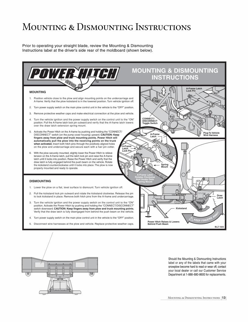
Prior to operating your straight blade, review the Mounting & DismountingInstructions label at the driver’s side rear of the moldboard (shown below).
Power Hitch Raises & LowersBehind Push Beam
Kickstand
DrawLatch
KEEP FINGERS AWAY!
Plug To VehicleWire Harness
CONNECT /DISCONNECTToggle Switch
MOUNTING & DISMOUNTINGINSTRUCTIONS
MOUNTING
1. Position vehicle close to the plow and align mounting points on the undercarriage andA-frame. Verify that the plow kickstand is in the lowered position. Turn vehicle ignition off.
2. Turn power supply switch on the main plow control unit in the vehicle to the “OFF” position.
3. Remove protective weather caps and make electrical connection at the plow and vehicle.
4. Turn the vehicle ignition and the power supply switch on the control unit to the “ON”position. Pull the A-frame latch lock pin outward and verify that the A-frame latch lowersover the draw latch extension spring mount.
5. Activate the Power Hitch on the A-frame by pushing and holding the “CONNECT/ DISCONNECT” switch (on the pump cover housing) upward. CAUTION: Keepfingers away from plow and truck mounting points. Power Hitch willautomatically pull the plow into the receiving points on the truckwhen activated. Insert both hitch pins through the positively aligned holeson the plow and undercarriage and secure each with a hair pin cotter.
6. With the plow securely mounted, slightly lower the Power Hitch to relievetension on the A-frame latch, pull the latch lock pin and raise the A-frame
latch until it locks into position. Raise the Power Hitch and verify that thedraw latch is fully engaged behind the push beam on the vehicle. Rotatethe kickstand counterclockwise until it locks into place. The plow is nowproperly mounted and ready to operate.
DISMOUNTING
1. Lower the plow on a flat, level surface to dismount. Turn vehicle ignition off.
2. Pull the kickstand lock pin outward and rotate the kickstand clockwise. Release the pinto lock kickstand in place. Remove both hitch pins from the A-frame and undercarriage.
3. Turn the vehicle ignition and the power supply switch on the control unit to the “ON”position. Activate the Power Hitch by pushing and holding the “CONNECT/DISCONNECT”switch downward. CAUTION: Keep fingers away from plow and truck mounting points.Verify that the draw latch is fully disengaged from behind the push beam on the vehicle.
4. Turn power supply switch on the main plow control unit in the vehicle to the “OFF” position.
5. Disconnect wire harnesses at the plow and vehicle. Replace protective weather caps.
TM
A-Frame LatchLock Pin
A-Frame LatchRotates ClockwiseAnd Hooks Onto
Spring Mount
A-FrameLatch
SpringMount
A-FrameLatchLock Pin
BLZ 1023
Should the Mounting & Dismounting Instructionslabel or any of the labels that came with yoursnowplow become hard to read or wear off, contactyour local dealer or call our Customer ServiceDepartment at 1-888-680-8600 for replacements.

14 Regular Maintenance
Regular Maintenance
Your Blizzard straight blade snowplow has been designed for years of rugged,dependable service with low maintenance. To ensure proper working condition,follow the maintenance guidelines below and on the next page.
CAUTION: Always follow the maintenance guidelines in a timely fashion. Failure to observe maintenance guidelines may result in poor snowplow operation, increased component wear or part failure.
Routinely inspect the following items – perform maintenance as needed:
1. All fasteners, pins, nuts and bolts for tightness. See the recommendedmaximum bolt torque chart on page 4.
2. All hydraulic hoses and hydraulic hose adapters for wear and leaks.
3. All hydraulic cylinders for leaks; inspect rod ends for corrosion and pitting.
4. Cutting edges and plow shoes for wear.
5. Clean and lubricate all electrical plugs, headlight connections, ground and battery cables, solenoid connections and switch connections to prevent corrosion. Apply white lithium grease at least once a month or every 75 hours of plow operation.
6. Clean and cover deep scratches or exposed metal with Blizzard white touch-up paint. Contact your local dealer for availability.
7. Check the hydraulic oil level in the hydraulic pump fluid reservoir. Fill the fluid to within 3/4" from the top of the reservoir. Do not exceed this level.Never mix different types of fluids. Contact your local dealer for replacement Blizzard Snowplow Rapid Action Hydraulic Oil.
Maintenance ScheduleMaintenance Performed Date

Storing Your Snowplow 15
Storing Your Snowplow
Placing Your Plow In Storage1. Position your plow on a flat, level surface for storage. Follow the dismount-
ing procedure illustrated on page 13.
2. Apply white lithium grease to all electrical plugs and connections. Cleanand install all dust caps.
3. Lubricate all exposed hydraulic cylinder rod ends with liquid white lithiumgrease.
4. Touch-up all rust spots or chipped paint with white Blizzard paint. Contactyour local dealer for availability.
5. Remove and properly discard the fluid in the pump reservoir. Clean thepump filter and replace the Blizzard Snowplow Rapid Action Hydraulic Oilto within 3/4" from the top of the reservoir. Changing the fluid annually willprolong the life of your pump and manifold.
6. Cover the snowplow with a tarp if stored outside.This will protect your plowfrom sun fading and inclement weather which can lead to accelerated corrosion.
Removing Your Plow From Storage
1. Perform all regular maintenance indicated on the previous page.
2. If you have not replaced the hydraulic oil in the pump reservoir, it is stronglyencouraged that you do so prior to operating your plow.
3. Follow the mounting procedure illustrated on page 13.
4. Once the plow has been properly mounted to the vehicle and all electricalconnections have been made, initiate all of the functions of the snowplow.Monitor the fluid level in the reservoir and fill to 3/4" from the top of thetank if needed.
5. Adjust the snowplow headlights as needed.
Annual Fluid ReplacementType & Quantity of Fluid Replaced Date

16 Plow Specifications
Moldboard
Length
760LD ..............................................................................7'-6"
760 ..................................................................................7'-6"
800 ..................................................................................8'-0"
Thickness ....................................................................12 Gauge
Height
760LD ................................................................................28"
760 & 800 ..........................................................................29"
Reinforcement
760LD ............................................................4 Ribs @ 3/16"
760 & 800 ........................................................6 Ribs @ 1/4"
Cutting Edge
760LD & 760 ..................................................3/8" x 6" (1080)
800 ................................................................1/2" x 6" (1080)
Finish..........................................................Powder Coat - White
Trip Mechanism
Trip Spring Type
760LD............................................(3) 3/8" Hooked Extension
760 & 800......................................(4) 3/8" Hooked Extension
Trip Spring Adjustment
760LD ..........................................(3) 5/8"-11 x 5" Spade Bolt
760 & 800 ..........................(4) 5/8"-11 x 6-11/16" Spade Bolt
A-frame
Material ............................................Rec. Tube & Channel Type
Hitch Pins..............................................3/4" x 4-3/4" Yellow Zinc
Emergency Hitch Pin ..............................1" x 5-3/4" Yellow Zinc
Finish ..........................................................Powder Coat - Black
Pump
Construction ........................Steel Housing w/Clear Plastic Tank
Type ............................................................Internal Gear Pump
Motor........................................................................12 V Starter
Volume Per Minute ..................................2.1 GPM @ 1500 PSI
Weight ................................................................................32 lb.
Mount..................................A-frame Install w/Hex Head Screws
Reservoir Capacity......................................................1.5 quarts
Controls ..............................................Toggle Switch & Joystick
Manifold
Construction ......................................Clear Anodized Aluminum
Ports ..........................................................................................4
Cartridge Valves ........................................................................6
Relief Valve................................................................................1
Flow Control Valve ....................................................................1
Weight ............................................................................13.8 lb.
Mount..................................A-frame Install w/Hex Head Screws
Maximum Flow Capacity ..................................................2 gpm
Angle Cylinders
Stroke
760LD ....................................................................................9-3/8"
760 & 800 ..................................................................................10"
Ram Diameter
All Models ..............................................................................1-3/4"
Bore Diameter
All Models ....................................................................................2"
Lower/Raise Cylinder
Stroke
760LD ....................................................................................4-1/4"
760 & 800 ..........................................................................4-21/32"
Ram Diameter
760LD ..........................................................................................1"
760 & 800 ..............................................................................1-1/4"
Bore Diameter
760LD ....................................................................................1-3/4"
760 & 800 ..............................................................................2-1/2"
Plow Headlights
Type ..........................................................Low Profile w/Turn Signals
Measurements ..........................................10-3/4" W x 5"H x 5-3/2"D
Housing ..................................................................Plastic Composite
Mount ..................................................................Adjustable Ball Type
Bulb Type ......................High/Low Sealed Beam Halogen, 12V Rect.
Switch Type ........................................................Dash Mount, Toggle
Miscellaneous
Plow Weight*
760LD......................................................................Approx. 550 lb.
760 ..........................................................................Approx. 720 lb.
800 ..........................................................................Approx. 750 lb.
Adjustable Plow Shoes
760LD..........................................................................(2) Standard
760 & 800..............................................(2) Heavy-Duty Cast Steel
Mount Mechanism ............................................Hydraulic Draw Latch
Control Station ........................................................................Joystick
*Plow weight does not include vehicle undercarriage.
Unless otherwise indicated, all specifications are for Models 760LD, 760 & 800 snowplows.
Plow Specifications

Notes 17
Notes
Snowplow Serial Number
Hydraulic Pump Serial Number
Telephone Number
Dealer/Distributor
Date of Purchase

Ref. Part Quantity Part DescriptionNo. No.
1 81006 1 N/A N/A Moldboard - Model 760LD84006 N/A 1 N/A Moldboard - Model 76080006 N/A N/A 1 Moldboard - Model 800
2 61165 1 N/A N/A Moldboard Cutting Edge (1080) - Model 760LD 61168 N/A 1 N/A Moldboard Cutting Edge (1080) - Model 760 61209 N/A N/A 1 Moldboard Cutting Edge (1080) - Model 800
3 61196 8 8 8 1/2"-13 x 1-1/2" P Carriage Bolt4 61026 14 14 14 1/2", 1-1/16" O.D., 17/32" I.D. YZ SAE Mil-Carb High-Strength5 61020 13 13 13 1/2"-13 Grade C Z Top Lock Nut6A 61049 2 2 2 Plow Guide Assembly: (1) - 6 & 7, (2) - 8 & 96 61113 2 2 2 Plow Guide Tip, Black7 61050 2 2 2 27-1/4" Plow Guide, Red8 61051 4 4 4 5/16"-18 x 1" Grade 5 Z Hex Head Cap Screw9 61052 4 4 4 5/16"-18 Z Nylon Insert Lock Nut
10 61188 3 4 4 5/8"-11 Nylon Insert Lock Nut - Type NE11 61064 3 4 4 5/8", 1-5/16" O.D., 21/32" I.D. YZ SAE Mil-Carb High-Strength Washer12 61201 3 4 4 5/8"-11 x 5" Grade 8 Z Clear Chromate Spade Bolt13 61167 3 N/A N/A 3/8" x 2-5/8" O.D. x 12-1/2" Extension Spring - Model 760LD
61099 N/A 4 4 3/8" x 2-5/16" O.D. x 14-1/2" Extension Spring - Models 760 & 80014A 61098 2 N/A N/A Standard Plow Shoe Assembly - Model 760LD: (1) - 14, 15, 17, (18) - 16
61220 N/A 2 2 Heavy-Duty Plow Shoe Assembly - Models 760 & 800: (1) - 14, 15, 17, (18) - 1614 61104 2 N/A N/A Standard Plow Shoe (7-3/4" Shaft) - Model 760LD
61221 N/A 2 2 Cast Iron Heavy-Duty Plow Shoe (8-3/8" Shaft) - Models 760 & 80015 61102 2 2 2 1-5/8" O.D, 1-1/8" I.D. x 1-1/2" YZ Spacer16 61101 36 36 36 1", 1-3/4" O.D., 1-1/16" I.D. Z Flat Washer17 61103 2 2 2 1/2" x 1-3/4" Linch Pin18 61152 1 1 1 1/2"-13 x 4-1/2" Grade 8 YZ Hex Cap Screw19 41038 1 1 1 Kickstand Leg Weldment 20 41047 1 1 1 Kickstand Foot Weldment21 61057 4 4 4 1/2"-13 x 1-1/4" Grade 8 YZ Hex Cap Screw22 61293 1 1 1 1-1/8" O.D. x 53/64" I.D. x 2" Compression Spring 23 41037 1 1 1 3/8" x 1-1/8" O.D. x 35/64" I.D. Stepped Bushing 24 61314 2 2 2 3/4"-10 x 3-1/2" (with 2-1/2" Shank) Grade 8 YZ Hex Cap Screw25 61006 7 8 8 3/4"-10 Grade C Z Top Lock Nut26 61063 1 N/A N/A 5/8"-11 Grade C Z Top Lock Nut - Model 760LD27 83000 1 N/A N/A Pivot Beam Weldment - Model 760LD
41041 N/A 1 1 Pivot Beam Weldment - Models 760 & 80028 61002 N/A 4 4 3/4"-10 x 5" Grade 8 YZ Hex Cap Screw
61004 4 N/A N/A 3/4"-10 x 4-1/2" Grade 8 YZ Hex Cap Screw29 61252 1 N/A N/A 1"-8 x 8-1/2" Grade 8 YZ Hex Head Cap Screw - Model 760LD
61131 N/A 1 1 1"-8 x 9" Grade 8 YZ Hex Head Cap Screw - Models 760 & 80030 61008 1 1 1 1"-8 Grade C Z Top Lock Nut31 60065 2 N/A N/A Hydraulic Cylinder - Plow Angle - Model 760LD
60129 N/A 2 2 Hydraulic Cylinder - Plow Angle - Models 760 & 80032 60005 3 3 3 9/16"-18 x 9/16"-18 90˚ Adjustable Elbow O.R.B. Adapter33 60091 1 1 1 3/8" x 24" Hydraulic Hose (#1) - Plow Angle, Driver’s Side34 60011 1 1 1 3/8" x 24" Hydraulic Hose (#2) - Plow Angle, Passenger’s Side35 61253 1 N/A N/A 5/8"-11 x 5-1/2" Grade 8 YZ Hex Cap Screw - Model 760LD
61005 N/A 1 1 3/4"-10 x 6" Grade 8 YZ Hex Cap Screw - Models 760 & 80036 60092 1 1 1 1/4" x 17" Hydraulic Hose - Str./45˚ (#3) - Plow Raise/Lower, Extend37 60002 1 1 1 7/16"-20 x 7/16"-20 45˚ Adjustable Elbow O.R.B. Adapter38 60118 1 N/A N/A Hydraulic Cylinder - Plow Raise/Lower - Model 760LD
60130 N/A 1 1 Hydraulic Cylinder - Plow Raise/Lower - Models 760 & 80039 60004 1 1 1 7/16"-20 x 7/16"-20 Male O.R.B. Connector Adapter40 60093 1 1 1 1/4" x 15" Hydraulic Hose - Str./45˚ (#4) - Plow Raise/Lower, Retract41 61203 1 N/A N/A 1", 2" O.D., 1-1/16" I.D. YZ SAE Mil-Carb High-Strength Washer - Model 760LD42 61053 1 1 1 3/16" x 1-11/16" O.D. x 12" Z Compression Spring43 61211 1 N/A N/A 1", 2-1/4" O.D., 1-1/16" I.D. Flat Washer - Model 760LD44 61032 N/A 2 2 1-1/4", 2-1/2" O.D., 1-3/8" I.D. YZ SAE Mil-Carb High-Strength Washer - Models 760 & 80045 61017 3 3 3 3/8"-16 Z Wing Nut46 61012 3 3 3 3/8"-16 x 3/4" Grade 8 YZ Hex Cap Screw47 61016 6 6 6 3/8", 13/16" O.D., 13/32" I.D., YZ SAE Mil-Carb High-Strength Washer48 61014 1 1 1 3/8"-16 Z Jam Nylon Insert Lock Nut - Type NTE49 61116 1 1 1 3/8"-16 x 1-1/2" Threaded Stud50 40004 1 1 1 Pump Mount Hinge Weldment51 61218 1 1 1 3/8"-16 x 2" Grade 8 YZ Hex Cap Screw52 61034 2 2 2 3/8"-16 Grade C Z Top Lock Nut53 61222 2 2 2 3/8" YZ High-Alloy Split Lock Washer54 61033 3 3 3 3/8"-16 x 1" Grade 8 YZ Hex Cap Screw55 62019 2 2 2 7/16"-14 Hex Jam Nut56 61223 1 1 1 7/16" Internal Tooth Lock Washer57 61224 1 1 1 7/16", 23/32" O.D, 15/32" I.D. Key Washer58 62038 1 1 1 DPDT, (On)-Off-(On) Toggle Switch, 16 Amps, 115V AC - Draw Latch Connect/Disconnect59 61307 1 1 1 3/8" Internal/External Tooth Lock Washer60 82047 1 1 1 Diode Pack Mount Bracket
18 Models 760LD, 760 & 800 Parts List (1 of 4)
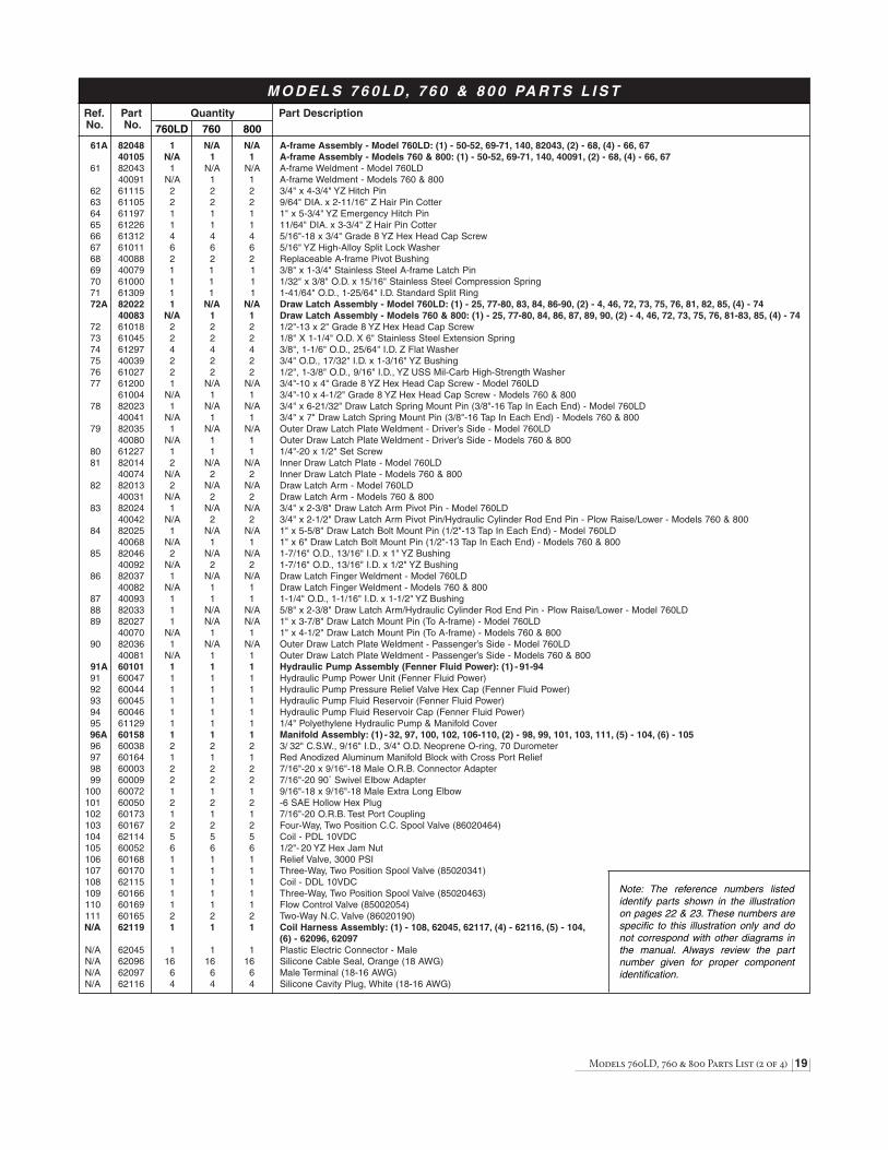
M O D E L S 7 6 0 L D, 7 6 0 & 8 0 0 PA R T S L I S T
760LD 760 800
Note: The reference numbers listedidentify parts shown in the illustrationon pages 22 & 23. These numbers arespecific to this illustration only and donot correspond with other diagrams inthe manual. Always review the partnumber given for proper componentidentification.
Ref. Part Quantity Part DescriptionNo. No.
61A 82048 1 N/A N/A A-frame Assembly - Model 760LD: (1) - 50-52, 69-71, 140, 82043, (2) - 68, (4) - 66, 6740105 N/A 1 1 A-frame Assembly - Models 760 & 800: (1) - 50-52, 69-71, 140, 40091, (2) - 68, (4) - 66, 67
61 82043 1 N/A N/A A-frame Weldment - Model 760LD40091 N/A 1 1 A-frame Weldment - Models 760 & 800
62 61115 2 2 2 3/4" x 4-3/4" YZ Hitch Pin63 61105 2 2 2 9/64" DIA. x 2-11/16" Z Hair Pin Cotter64 61197 1 1 1 1" x 5-3/4" YZ Emergency Hitch Pin65 61226 1 1 1 11/64" DIA. x 3-3/4" Z Hair Pin Cotter66 61312 4 4 4 5/16"-18 x 3/4" Grade 8 YZ Hex Head Cap Screw67 61011 6 6 6 5/16" YZ High-Alloy Split Lock Washer68 40088 2 2 2 Replaceable A-frame Pivot Bushing69 40079 1 1 1 3/8" x 1-3/4" Stainless Steel A-frame Latch Pin70 61000 1 1 1 1/32" x 3/8" O.D. x 15/16" Stainless Steel Compression Spring71 61309 1 1 1 1-41/64" O.D., 1-25/64" I.D. Standard Split Ring72A 82022 1 N/A N/A Draw Latch Assembly - Model 760LD: (1) - 25, 77-80, 83, 84, 86-90, (2) - 4, 46, 72, 73, 75, 76, 81, 82, 85, (4) - 74
40083 N/A 1 1 Draw Latch Assembly - Models 760 & 800: (1) - 25, 77-80, 84, 86, 87, 89, 90, (2) - 4, 46, 72, 73, 75, 76, 81-83, 85, (4) - 74 72 61018 2 2 2 1/2"-13 x 2" Grade 8 YZ Hex Head Cap Screw73 61045 2 2 2 1/8" X 1-1/4" O.D. X 6" Stainless Steel Extension Spring74 61297 4 4 4 3/8", 1-1/6" O.D., 25/64" I.D. Z Flat Washer75 40039 2 2 2 3/4" O.D., 17/32" I.D. x 1-3/16" YZ Bushing76 61027 2 2 2 1/2", 1-3/8" O.D., 9/16" I.D., YZ USS Mil-Carb High-Strength Washer77 61200 1 N/A N/A 3/4"-10 x 4" Grade 8 YZ Hex Head Cap Screw - Model 760LD
61004 N/A 1 1 3/4"-10 x 4-1/2" Grade 8 YZ Hex Head Cap Screw - Models 760 & 80078 82023 1 N/A N/A 3/4" x 6-21/32" Draw Latch Spring Mount Pin (3/8"-16 Tap In Each End) - Model 760LD
40041 N/A 1 1 3/4" x 7" Draw Latch Spring Mount Pin (3/8"-16 Tap In Each End) - Models 760 & 80079 82035 1 N/A N/A Outer Draw Latch Plate Weldment - Driver’s Side - Model 760LD
40080 N/A 1 1 Outer Draw Latch Plate Weldment - Driver’s Side - Models 760 & 80080 61227 1 1 1 1/4"-20 x 1/2" Set Screw81 82014 2 N/A N/A Inner Draw Latch Plate - Model 760LD
40074 N/A 2 2 Inner Draw Latch Plate - Models 760 & 80082 82013 2 N/A N/A Draw Latch Arm - Model 760LD
40031 N/A 2 2 Draw Latch Arm - Models 760 & 80083 82024 1 N/A N/A 3/4" x 2-3/8" Draw Latch Arm Pivot Pin - Model 760LD
40042 N/A 2 2 3/4" x 2-1/2" Draw Latch Arm Pivot Pin/Hydraulic Cylinder Rod End Pin - Plow Raise/Lower - Models 760 & 80084 82025 1 N/A N/A 1" x 5-5/8" Draw Latch Bolt Mount Pin (1/2"-13 Tap In Each End) - Model 760LD
40068 N/A 1 1 1" x 6" Draw Latch Bolt Mount Pin (1/2"-13 Tap In Each End) - Models 760 & 80085 82046 2 N/A N/A 1-7/16" O.D., 13/16" I.D. x 1" YZ Bushing
40092 N/A 2 2 1-7/16" O.D., 13/16" I.D. x 1/2" YZ Bushing86 82037 1 N/A N/A Draw Latch Finger Weldment - Model 760LD
40082 N/A 1 1 Draw Latch Finger Weldment - Models 760 & 80087 40093 1 1 1 1-1/4" O.D., 1-1/16" I.D. x 1-1/2" YZ Bushing88 82033 1 N/A N/A 5/8" x 2-3/8" Draw Latch Arm/Hydraulic Cylinder Rod End Pin - Plow Raise/Lower - Model 760LD89 82027 1 N/A N/A 1" x 3-7/8" Draw Latch Mount Pin (To A-frame) - Model 760LD
40070 N/A 1 1 1" x 4-1/2" Draw Latch Mount Pin (To A-frame) - Models 760 & 80090 82036 1 N/A N/A Outer Draw Latch Plate Weldment - Passenger’s Side - Model 760LD
40081 N/A 1 1 Outer Draw Latch Plate Weldment - Passenger’s Side - Models 760 & 80091A 60101 1 1 1 Hydraulic Pump Assembly (Fenner Fluid Power): (1) - 91-9491 60047 1 1 1 Hydraulic Pump Power Unit (Fenner Fluid Power)92 60044 1 1 1 Hydraulic Pump Pressure Relief Valve Hex Cap (Fenner Fluid Power)93 60045 1 1 1 Hydraulic Pump Fluid Reservoir (Fenner Fluid Power)94 60046 1 1 1 Hydraulic Pump Fluid Reservoir Cap (Fenner Fluid Power)95 61129 1 1 1 1/4" Polyethylene Hydraulic Pump & Manifold Cover96A 60158 1 1 1 Manifold Assembly: (1) - 32, 97, 100, 102, 106-110, (2) - 98, 99, 101, 103, 111, (5) - 104, (6) - 105 96 60038 2 2 2 3/ 32" C.S.W., 9/16" I.D., 3/4" O.D. Neoprene O-ring, 70 Durometer 97 60164 1 1 1 Red Anodized Aluminum Manifold Block with Cross Port Relief98 60003 2 2 2 7/16"-20 x 9/16"-18 Male O.R.B. Connector Adapter99 60009 2 2 2 7/16"-20 90˚ Swivel Elbow Adapter
100 60072 1 1 1 9/16"-18 x 9/16"-18 Male Extra Long Elbow101 60050 2 2 2 -6 SAE Hollow Hex Plug102 60173 1 1 1 7/16"-20 O.R.B. Test Port Coupling103 60167 2 2 2 Four-Way, Two Position C.C. Spool Valve (86020464)104 62114 5 5 5 Coil - PDL 10VDC105 60052 6 6 6 1/2"- 20 YZ Hex Jam Nut106 60168 1 1 1 Relief Valve, 3000 PSI107 60170 1 1 1 Three-Way, Two Position Spool Valve (85020341)108 62115 1 1 1 Coil - DDL 10VDC109 60166 1 1 1 Three-Way, Two Position Spool Valve (85020463)110 60169 1 1 1 Flow Control Valve (85002054)111 60165 2 2 2 Two-Way N.C. Valve (86020190)N/A 62119 1 1 1 Coil Harness Assembly: (1) - 108, 62045, 62117, (4) - 62116, (5) - 104,
(6) - 62096, 62097N/A 62045 1 1 1 Plastic Electric Connector - MaleN/A 62096 16 16 16 Silicone Cable Seal, Orange (18 AWG)N/A 62097 6 6 6 Male Terminal (18-16 AWG)N/A 62116 4 4 4 Silicone Cavity Plug, White (18-16 AWG)
Models 760LD, 760 & 800 Parts List (2 of 4) 19
M O D E L S 7 6 0 L D, 7 6 0 & 8 0 0 PA R T S L I S T
760LD 760 800
Note: The reference numbers listedidentify parts shown in the illustrationon pages 22 & 23. These numbers arespecific to this illustration only and donot correspond with other diagrams inthe manual. Always review the partnumber given for proper componentidentification.

Ref. Part Quantity Part DescriptionNo. No.
N/A 62117 1 1 1 3/8" I.D. Copper End Ring Terminal, 8 Gauge - Coil Harness112 61010 2 2 2 5/16"-18 x 3-3/4" Grade 8 YZ Hex Cap Screw113A 62040 1 1 1 Vehicle Wire Harness Assembly (2000-01): (1) - 113, 114, 62122, 62008, 62009, 62024, 62048, 62049, (2) - 62035,
(3) - 62016, (4) - 62072,113 62047 1 1 1 Vehicle Wire Harness (2000-01)114 62000 1 1 1 Rubber Weather Cap - Vehicle Wire Harness (2000-01)N/A 62035 2 2 2 Rubber Weather Cap - Plow Headlight ConnectorN/A 62024 1 1 1 DPDT, On-Off-On Toggle Switch, 15A, 125V AC (Vehicle/Plow Headlights)N/A 62048 1 1 1 1/4" DIA. x 1-1/4" BUSS AGC 10A, 250V FuseN/A 62049 1 1 1 72" Power Cable, Red - Power Contactor to BatteryN/A 62122 1 1 1 54" Ground Cable, Black - Harness to BatteryN/A 62072 4 4 4 3/8" I.D. Copper End Ring Terminals, 4 Gauge - 72" Power Cable / 54" Ground Cable N/A 62008 1 1 1 Mini Fuse ClipN/A 62009 1 1 1 Auto Blade Fuse ClipN/A 62016 3 3 3 Splice Lock Connector (18 -14 AWG)115A 62112 1 1 1 Vehicle Wire Harness Assembly - Relay Version (2001-02): (1) - 106, 107, 62008, 62009, 62024, 62048, 62049, (2) - 62035,
62072, (3) - 62016115 62111 1 1 1 Vehicle Wire Harness - Relay Version (2001-02)N/A 62124 1 1 1 1/4" DIA. x 1-1/4" BUSS AGC 15A, 32V FuseN/A 62113 1 1 1 Main Lighting Harness - Relay Version (2001-2002)N/A 62125 1 1 1 3PDT, Headlight Relay, 20A, 12V N/A 62126 1 1 1 24" Ground Lead (Green/Yellow Wire) with #10 Ring TerminalN/A 62127 1 1 1 24" On/Off Plow Light Switch Lead (Green/Yellow Wires) with Two 1/4" ReceptaclesN/A 62042 1 1 1 Heavy Duty, Water-Resistant DC Power ContactorN/A 61228 4 4 4 5/16"- 24 Z Hex Jam NutN/A 61229 4 4 4 #10 - 32 Z Hex Full NutN/A 61230 2 2 2 #10 Z Medium Split Lock WasherN/A 62056 1 1 1 24" Power Contactor Ground Wire116A 62039 1 1 1 Plow Wire Harness Assembly (2000-02): (10) - 56-58, 116, 117, 62006, 62046, (2) - 55, (10) - 62093, 62096116 62057 1 1 1 Plow Wire Harness (2000-02)117 62001 1 1 1 Rubber Weather Cap - Plow Wire HarnessN/A 62046 1 1 1 Plastic Electric Connector - FemaleN/A 62006 1 1 1 Diode Board Assembly - Plow Wire Harness: (1) - 62007, 62090, 62092, 62094, 62095, (5) - 62091, 62093 N/A 62007 1 1 1 Diode Board Cover, ClearN/A 62090 1 1 1 Diode Board Connector Body w/GasketN/A 62091 5 5 5 Silicone Cable Seal, Green (16 AWG)N/A 62092 1 1 1 Silicone Cavity Plug, Green (16 AWG)N/A 62093 15 15 15 Female Terminal (18-16 AWG)N/A 62094 1 1 1 Circuit Board (MPM-90-8315-00)N/A 62095 1 1 1 Six-Way Secondary Lock118A 62058 1 1 1 Plow Headlight Assembly: (1) - 118/119, 120-123, 62061, 62062118 62059 1 1 1 Plow Headlight - Driver’s Side 119 62060 1 1 1 Plow Headlight - Passenger’s Side120 62032 2 2 2 Plow Headlight Wire Harness with 5-pin PlugN/A 62061 2 2 2 Plow Headlight Glass Sealed Beam Halogen Bulb (H6545/H4666)121 61231 2 2 2 Headlight Ball Stud Mount Adapter122 61232 2 2 2 1/2" Heavy Split Lock WasherN/A 62062 1 1 1 NYK Corrosion Preventive Compound (2 fl.oz.)123 61025 2 2 2 1/2"-13 Grade 8 YZ Hex Nut124 61166 2 2 2 2-1/4" Molded Nylon Dome Plug, Black125 39034 1 N/A N/A Light Tower, Round Mounting Tube - Model 760LD
39032 N/A 1 1 Light Tower, Round Mounting Tube - Models 760 & 800126 61038 2 2 2 1/4"-20 Grade C Z Top Lock Nut127 61039 2 2 2 1/4", 5/8" O.D., 9/32" I.D. YZ SAE Mil-Carb High-Strength Washer128 39023 1 1 1 Stainless Steel Vehicle Wire Harness Plug Mount129 61037 2 2 2 1/4"-20 x 3/4" Grade 8 YZ Hex Cap Screw130A 62073 1 1 1 Joystick Control Station Assembly: (1) - 130, 131, 132, 137, (4) - 133130 62074 1 1 1 Joystick Control Station131 61185 1 1 1 1/8" ABS Plastic Joystick Control Station Base Plate132 61127 1 1 1 61" Velcro Strap with 2" Metal D-Ring, Black133 61254 4 4 4 8-32 x 3/4" Pan Head Machine Screw Z134 61041 1 1 1 Vehicle/Plow Headlight Toggle Switch Bracket135 61031 7 7 7 12-14 x 3/4" Hex Washer Self-Drilling Screw136 61088 1 1 1 Plow/Vehicle Headlight Toggle Switch Bracket Label137 61174 1 1 1 Joystick Control Station Label138 61085 N/A 1 1 2-1/8" x 13-1/8" Push Beam Decal139 61128 1 N/A N/A 1-1/2" x 9" Push Beam Decal140 61295 1 1 1 Power Hitch Connect/Disconnect Switch Label141 61302 1 1 1 Sequencing Valve & Hydraulic Hose Identification Guide Label142 61177 1 1 N/A Passenger’s Side Moldboard Decal - Models 760LD & 760
61179 N/A N/A 1 Passenger’s Side Moldboard Decal - Model 800143 61181 1 1 1 WARNING! Label144 61175 1 1 1 Center Moldboard Decal145 61180 1 1 1 Power Hitch Mounting & Dismounting Instructions Label
20 Models 760LD, 760 & 800 Parts List (3 of 4)
M O D E L S 7 6 0 L D, 7 6 0 & 8 0 0 PA R T S L I S T
760LD 760 800
Note: The reference numbers listedidentify parts shown in the illustrationon pages 22 & 23. These numbers arespecific to this illustration only and donot correspond with other diagrams inthe manual. Always review the partnumber given for proper componentidentification.

Ref. Part Quantity Part DescriptionNo. No.
146 61176 1 1 N/A Driver’s Side Moldboard Decal - Models 760LD & 76061178 N/A N/A 1 Driver’s Side Moldboard Decal - Model 800
147 61199 1 N/A N/A Serial Number Label (Sequentially Numbered) - Model 760LD61183 N/A 1 N/A Serial Number Label (Sequentially Numbered) - Model 76061184 N/A N/A 1 Serial Number Label (Sequentially Numbered) - Model 800
148 30037 N/A 1 1 1999-2002 Chevrolet/GMC 2500 Series Undercarriage (37" Push Beam)
N/A 61202 1 N/A N/A Hardware Kit #1: (1) - 41, 43, 60, 129, (2) - 24, (3) - 10, 11, 12, (4) - 28, (6) - 25 N/A 61191 N/A 1 1 Hardware Kit #1: (1) - 52, 54, 60, 129, (2) - 24, 44, (4) - 10, 11, 12, 28, (6) - 25 N/A 61192 1 1 1 Hardware Kit #2: (1) - 46, 48, 49, 52, 54, 59,134, (2) - 126, 127, 129, (3) - 45, (4) - 47, 135 N/A 60161 1 1 1 Hydraulic Adapter Kit: (1) - 37, 39, 100, (2) - 98, 99, (3) - 32 N/A 60186 1 1 1 Hydraulic Hose Kit: (1) - 33, 34, 36, 40N/A 61255 1 1 1 Moldboard Cutting Edge Hardware Kit - Kit Includes: (8) - 3, 4, 5N/A 61256 1 N/A N/A Moldboard Cutting Edge with Hardware Kit, Model 760LD - Kit Includes: 61165, 61255N/A 61258 N/A 1 N/A Moldboard Cutting Edge with Hardware Kit, Model 760 - Kit Includes: 61168, 61255 N/A 61259 N/A N/A 1 Moldboard Cutting Edge with Hardware Kit, Model 800 - Kit Includes: 61209, 61255
Models 760LD, 760 & 800 Parts List (4 of 4) 21
M O D E L S 7 6 0 L D, 7 6 0 & 8 0 0 PA R T S L I S T
760LD 760 800
Note: The reference numbers listedidentify parts shown in the illustrationon pages 22 & 23. These numbers arespecific to this illustration only and donot correspond with other diagrams inthe manual. Always review the partnumber given for proper componentidentification.

113A
113
115A
115
114
116
116A
117
1
2 3
4
5
9
10
11
1213
14A1415
16
17 18
1920
54
21
22 235
24
25
2525
25
2728
28
28
29
30
31
3233
35 36 37
38
39
40
41/44
42
43/44
45
4748
49
47
51
5354
5556
60
71 6970
72
140
143
144145
146
147

Blizzard is a trademark of Blizzard Corporation. Blizzard is registered in the United States Patent and Trademark Office. Blizzard Straight BladeSnowplows are protected by U.S. Patent 6,276,076. Other patents pending.
Blizzard Corporation reserves the right, under its Continuous Improvement Policy, to changeconstruction or design details and furnish equipment when so altered without reference toillustrations or specifications. Blizzard Corporation offers a one-year limited warranty for alland accessories or damage resulting from the use of these unauthorized items.
Models 760LD, 760 & 800 Assembly Schematic
6
6A
7
8
25
25
25/26
28
31
3234
45
46
47
47
50
52
5457
58 5259
61A61
62
63
64 65 6667 68
72A
2 4
73
4674
75 76
77
78
7980 81
8384
82
85
86
87
83/88
89
90
91A91
92 93
94
95
96A - SEE DETAIL ON PAGE 24
96
67
112
112
141
142
118
118A
119
120
121
122123
124
125
126127
128
129
130A
130
131
132
133
134135
136
137
138/13921
148
45

24 Manifold Detail & Hydraulic Schematic
STRAIGHT BLADE HYDRAULICSCHEMATIC (2001-2002)
RIGHT ANGLE
LEFT ANGLE
3000 PSI1
RV
2
S3 S4
TGP
PGP
S6
T1 P1
S5
S8
S7
FC
RAISE LOWER3 4
LIFT CYL.
97
99
32
102
101
103
104
105
106
103
104
107
108 109
104
105
104
110
111 101
111104
98
99
100
OneFlat
TwoFlats
Torque Table for 37˚AdaptersPort
ThreadSize
AssemblyTorque
(foot-pounds)
OriginalAssembly
(F.F.F.T.)
7/16-209/16-18
15 ± 1.018 ± 2.0
2.5 ± .252.5 ± .25
Torque Table for O.R.B. AdaptersPort
ThreadSize
AssemblyTorque
(foot-pounds)
OriginalAssembly
(F.F.F.T.)
7/16-209/16-18
15 ± 1.025 ± 2.0
1.5 ± .251.5 ± .25
F.F.F.T. = Flats From Finger Tight

Diagram - Molded Plug Pin Locations (2000-01) 25
PLOW HARNESS PLUG (2001-2002)END VIEW LOOKING AT MALE CONNECTOR
VEHICLE HARNESS PLUG (2001-2002)END VIEW LOOKING AT FEMALE CONNECTOR
BLIZZARD HARNESS PLUG (PLOW)UNIVERSAL 14 + 2 MOLD
PIN COLOR FUNCTION AWGNO.
BLACK GROUND 4N/A N/A N/A
2 RED 12 VOLT DC (+) 43 BROWN PUMP SOLENOID 184 RED/WHITE RIGHT SLIDE BOX EXTEND 185 RED/BLACK RIGHT SLIDE BOX RETRACT 186 BLUE/WHITE LEFT SLIDE BOX EXTEND 187 BLUE/BLACK LEFT SLIDE BOX RETRACT 188 BLUE LEFT ANGLE 189 GREEN RIGHT ANGLE 18
10 WHITE LIFT 1811 ORANGE FLOAT 1812 N/A N/A N/A13 N/A N/A N/A14 N/A N/A N/A15 PINK/BLACK 12 (+) VDC FUSED 1816 N/A N/A 18
BLIZZARD HARNESS PLUG (VEHICLE)UNIVERSAL 14 + 2 MOLD
PIN COLOR FUNCTION AWGNO.
BLACK GROUND 4BLACK GROUND 18
2 RED 12 VOLT DC (+) 4BROWN/WHITE PUMP SOLENOID TO RING 18BROWN PUMP SOLENOID TO MOLEX 18
4 RED/WHITE RIGHT SLIDE BOX EXTEND 185 RED/BLACK RIGHT SLIDE BOX RETRACT 186 BLUE/WHITE LEFT SLIDE BOX EXTEND 187 BLUE/BLACK LEFT SLIDE BOX RETRACT 188 BLUE LEFT ANGLE 189 GREEN RIGHT ANGLE 18
10 WHITE LIFT 1811 ORANGE FLOAT 1812 N/A N/A N/A13 N/A N/A N/A14 N/A N/A N/A15 PINK/BLACK 12 (+) VDC FUSED 1816 N/A N/A 18
1
3
FEMALE TERMINALS
MALE TERMINALS
4
STRIPECOLOR(BLACK)
WIRECOLOR(BLUE)
PIN NUMBER
STRIPECOLOR(WHITE)
WIRECOLOR(RED)
PIN NUMBER
EXAMPLE
7
1
5 7
15
11
6 83
21 10
12 13 14 16
RED BLUE/BLACK
ORANGE
TOP
WHITEBLACK
BROWN
GREEN
9
43
BROWN/WHITE
RED/WHITE
1
BLACK
RED/BLACK
BLUE/WHITE
PINK/BLACK
BLUE
6
15
STRIPECOLOR(BLACK)
WIRECOLOR(PINK)
PIN NUMBER
STRIPECOLOR(WHITE)
WIRECOLOR(BLUE)
PIN NUMBER
EXAMPLE
4 3
11 2 110 9
12131416
TOPBLUE/BLACK
RED/BLACK
BLUE/WHITE
78BLUE
ORANGE
RED
6 5
BLACK
BROWN
GREEN
PINK/BLACK
15
WHITE
RED/WHITE

26 Diagram - Plow Harness (2000-02)
24"
1"
12"
CLA
MP
ING
LOC
ATIO
N
VE
HIC
LE H
AR
NE
SS
JAC
KE
T M
ATE
RIA
LB
LAC
K N
YLO
N B
RA
IDP
/N 6
2057
1"IN
SID
E H
YD
RA
ULI
CE
NC
LOS
UR
E
7"
1"
3"
12"
ABCDEF
OR
AN
GE
/WH
ITE
WH
ITE
OR
AN
GE
NO
T U
SE
DO
RA
NG
E/R
ED
OR
AN
GE
/BLA
CK
NO
TE
: GR
EA
SE
FE
MA
LE T
ER
MIN
ALS
DIO
DE
PA
CK
AS
SE
MB
LY (
P/N
620
06)
DIO
DE
PA
CK
CO
VE
R, C
LEA
R -
P/N
620
07C
ON
NE
CTO
R B
OD
Y W
/GA
SK
ET
- P
/N 6
2090
SIL
ICO
NE
RU
BB
ER
CA
BLE
SE
AL
- P
/N 6
2091
SIL
ICO
NE
RU
BB
ER
CA
VIT
Y P
LUG
- P
/N 6
2092
FE
MA
LE T
ER
MIN
AL
(18-
16 A
WG
) -
P/N
620
93C
IRC
UIT
BO
AR
D -
P/N
620
94S
IX-W
AY S
EC
ON
DA
RY
LO
CK
- P
/N 6
2095
HIG
H A
MP
WIR
ES
CO
LOR
S (
PIN
1 -
BLA
CK
, PIN
2 -
RE
D)
WIR
E (
SG
T 4
AW
G)
EN
D R
ING
TE
RM
INA
LS (
3/8"
I.D
.) -
P/N
620
72
PLO
W H
AR
NE
SS
(200
0-20
02)
WIT
H M
OLD
ED
PLU
GP
/N 6
2039
NO
T D
RA
WN
TO
SC
ALE
UN
LES
S O
TH
ER
WIS
E S
PE
CIF
IED
ALL
DIM
EN
SIO
NS
IN IN
CH
ES
EN
D V
IEW
LOO
KIN
G A
T C
ON
NE
CT
OR
NO
TE
: SE
E D
ETA
IL O
N P
AG
E 2
5
87
11
16
21
65
43
910
1514
1312
9"
PLA
ST
IC E
LEC
TR
IC C
ON
NE
CTO
R, F
EM
ALE
- P
/N 6
2046
SIL
ICO
NE
RU
BB
ER
CA
BLE
SE
AL
- P
/N 6
2096
FE
MA
LE T
ER
MIN
AL
(18-
16 A
WG
) -
P/N
620
93
RE
D
BLA
CK
TOP 7
31
56
28
4
EN
D
VIE
W
(5)
PIN
K/B
LAC
K
(6)
PIN
K/B
LAC
K
(3)
WH
ITE
(1)
BR
OW
N
(2)
BR
OW
N
(4)
OR
AN
GE
/RE
D
(7)
AN
D (
8) N
OT
US
ED
OT
TO C
ON
NE
CTO
RA
MP
TE
RM
INA
LS(1
8-14
AW
G)
(TW
O 1
8-14
AW
G)
PAC
KA
RD
GT
280
EL
EC
TR
IC C
ON
NE
CTO
R (
PL
OW
)
PIN
C
OL
OR
FU
NC
TIO
NA
WG
NO
.
AO
RA
NG
E/B
LAC
K(S
5) L
OW
ER
/FLO
AT18
BO
RA
NG
E/W
HIT
E(S
7) L
IFT
/FLO
AT18
CW
HIT
E(S
6) L
IFT
18D
OR
AN
GE
/RE
D(S
8) H
ITC
H L
OW
ER
18E
GR
EE
N(S
4) A
NG
LE R
IGH
T18
FB
LUE
(S3)
AN
GLE
LE
FT
18G
BLU
E/B
LAC
K(S
9) L
EF
T S
LID
E B
OX
RE
T.18
HB
LUE
/WH
ITE
(S10
) LE
FT
SLI
DE
BO
X E
XT.
18J
RE
D/B
LAC
K(S
1) R
IGH
T S
LID
E B
OX
RE
T.18
KR
ED
/WH
ITE
(S2)
RIG
HT
SLI
DE
BO
X E
XT.
18
AB
ED
C
KJ
HG
F
EN
D V
IEW
LOO
KIN
G A
T C
ON
NE
CT
OR
M2
M5
B1
B2
M4
M10
BL
IZZ
AR
D P
LU
G (
VE
HIC
LE
)U
NIV
ER
SA
L 1
4 +
2 M
OL
D
PIN
C
OL
OR
FU
NC
TIO
NA
WG
NO
.
BLA
CK
GR
OU
ND
4N
/A
N/A
N/A
2R
ED
12 V
DC
(+
)4
3B
RO
WN
PU
MP
SO
LEN
OID
184
RE
D/W
HIT
ER
IGH
T B
OX
EX
TE
ND
185
RE
D/B
LAC
KR
IGH
T B
OX
RE
TR
AC
T18
6B
LUE
/WH
ITE
LEF
T B
OX
EX
TE
ND
187
BLU
E/B
LAC
KLE
FT
BO
X R
ET
RA
CT
188
BLU
ELE
FT
AN
GLE
189
GR
EE
NR
IGH
T A
NG
LE18
10W
HIT
E
LIF
T18
11O
RA
NG
EF
LOAT
1812
N/A
N/A
N/A
13N
/AN
/AN
/A14
N/A
N/A
N/A
15P
INK
/BLA
CK
12 V
DC
(+
) F
US
ED
1816
N/A
N/A
N/A
1

Plow Harness Wire Schematic (2000-02) 27
PL
OW
HA
RN
ES
S W
IRE
SC
HE
MA
TIC
(20
00-2
002)
D3
D1
D4
D2 M3
M4
A B
C D
E F
123456
12
34
56
WH
ITE
OR
AN
GE
OR
AN
GE
/RE
D
A
OR
AN
GE
/BLA
CK
B
OR
AN
GE
/WH
ITE
C
WH
ITE
D
OR
AN
GE
/RE
D
E
GR
EE
N
F
BLU
E
G
BLU
E/B
LAC
K
H
BLU
E/W
HIT
E
J R
ED
/BLA
CK
K
RE
D/W
HIT
E
A B C D E F G H J KM5
MANIFOLD CONNECTORPAC
KA
RD
ELE
CT
RIC
CO
NN
EC
TOR
1 O
RA
NG
E/B
LAC
K =
A2
OR
AN
GE
/RE
D =
B3
NO
T U
SE
D =
C4
OR
AN
GE
= D
5 W
HIT
E =
E6
OR
AN
GE
/WH
ITE
= F
WHITE
ORANGE/RED
OR
AN
GE
/RE
DO
RA
NG
E/R
ED
PIN
K/B
LAC
K
PIN
K/B
LAC
K
WH
ITE
WH
ITE
BR
OW
N
BR
OW
N1 2 3 4 5 6 7 8
M10
1 2 3 4 5 6 7 8
5 6
4 33 2 1
S1
HIT
CH
SW
ITC
H
DP
DT
(O
N)-
OF
F-(
ON
)
NO
TE
: WH
ITE
IS O
NT
OP
TE
RM
INA
L
BR
OW
N
WH
ITE
PINK/BLACK
PIN
K/B
LAC
KP
INK
/BLA
CK
OR
AN
GE
WH
ITE
WH
ITE
GR
EE
N
BLU
E
BLU
E/B
LAC
K
BLU
E/W
HIT
E
RE
D/B
LAC
K
RE
D/W
HIT
E
BR
OW
N
GREEN
BLUE
BLUE/BLACK
BLUE/WHITE
RED/BLACK
RED/WHITE
RED
RE
DB
LAC
KB
2B
2
B2
B1
PU
MP
MO
TOR
MO
TOR
1
PIN
K/B
LAC
K
OR
AN
GE
WH
ITE
WH
ITE
GR
EE
N
BLU
E
BLU
E/B
LAC
K
BLU
E/W
HIT
E
RE
D/B
LAC
K
RE
D/W
HIT
E
BR
OW
N
16 15 14 13 12 11
N/A
VD
C F
US
ED
N/A
N/A
N/A
FLO
AT10
9 8 7 6 5 4 3 2 1
LIF
T
RIG
HT
AN
GLE
LEF
T A
NG
LE
DR
. SLI
DE
RE
T.
DR
. SLI
DE
EX
T.
PS
. SLI
DE
RE
T.
PU
MP
SO
L.
PO
S
NE
G
PS
. SLI
DE
EX
T.
RE
D #
6 A
WG
BLA
CK
#6
AW
G
M2
GR
EE
N
BLU
E
BLU
E/B
LAC
K
BLU
E/W
HIT
E
RE
D/B
LAC
K
RE
D/W
HIT
E
SE
E V
EH
ICLE
HA
RN
ES
S W
IRE
SC
HE
MAT
IC

28 Diagram - Vehicle Harness (2000-01)
A
BCD
E
12
34
56
78
910
1112
AB
CD
EF
AB
CD
EF
A
BCD
E
25"
45"
10"
8"
100"
5/8"
SP
LIT
LO
OM
TU
BIN
G
20"
20"
1/2"
SP
LIT
LO
OM
TU
BIN
G
5/8"
SP
LIT
LO
OM
TU
BIN
G
HIG
H A
MP
WIR
ES
- 7
8" L
ON
GB
LAC
K (
PIN
1)
- 60
" LO
NG
RE
D (
PIN
2)
- 54
" LO
NG
WIR
E (
SG
T 4
AW
G)
EN
D R
ING
TE
RM
INA
LS (
3/8"
I.D
.) -
P/N
620
72
RE
D A
WG
18
8" L
ON
GC
ON
NE
CT
S T
OM
1 P
IN #
15
FU
SE
HO
LDE
RB
US
S B
P/H
HB
AC
CE
PT
S A
GC
10
FU
SE
S 1
0-15
AM
PP
/N 6
2048
RE
D -
20"
LO
NG
HE
AD
LA
MP
SW
ITC
H -
2"
LON
GA
3 -
LOW
BE
AM
FE
ED
(L.
GR
EE
N)
A4
- H
IGH
BE
AM
FE
ED
(Y
ELL
OW
)A
5 -
LOW
BE
AM
PLO
W (
L. G
RE
EN
/BLA
CK
)A
6 -
HIG
H B
EA
M P
LOW
(Y
ELL
OW
/BLA
CK
)A
7 -
LOW
BE
AM
VE
HIC
LE (
GR
EE
N/R
ED
)A
8 -
HIG
H B
EA
M V
EH
ICLE
(Y
ELL
OW
/RE
D)
VE
HIC
LE H
AR
NE
SS
JAC
KE
T M
ATE
RIA
LB
LAC
K N
YLO
N B
RA
IDP
/N 6
2047
20"
8"
A =
CO
MM
ON
(W
HIT
E/R
ED
)B
= H
IGH
BE
AM
FE
ED
(Y
ELL
OW
)C
= L
OW
BE
AM
FE
ED
(L.
GR
EE
N)
D =
HIG
H B
EA
M (
YE
LLO
W/R
ED
)E
= L
OW
BE
AM
(L.
GR
EE
N/R
ED
)
PAC
KA
RD
ELE
CT
RIC
CO
NN
EC
TOR
PAC
KA
RD
ELE
CT
RIC
TE
RM
INA
LSC
AB
LE S
EA
L
TU
RN
(V
IOLE
T)
- A
11
RU
N (
GR
AY)
- A
1226
"
18"
28"
24"
18"
A =
CO
MM
ON
(W
HIT
E/R
ED
)B
= H
IGH
BE
AM
FE
ED
(Y
ELL
OW
)C
= L
OW
BE
AM
FE
ED
(L.
GR
EE
N)
D =
HIG
H B
EA
M (
YE
LLO
W/R
ED
)E
= L
OW
BE
AM
(L.
GR
EE
N/R
ED
)
PAC
KA
RD
ELE
CT
RIC
CO
NN
EC
TOR
PAC
KA
RD
ELE
CT
RIC
TE
RM
INA
LSC
AB
LE S
EA
L
TU
RN
(P
INK
)
26"
HAT
CH
= P
VC
SLE
EV
ING
1/2"
SP
LIT
LO
OM
TU
BIN
G
EN
D V
IEW
LOO
KIN
G A
TC
ON
NE
CTO
RDR
IVE
R'S
SID
EA
= C
OM
MO
N (
WH
ITE
/RE
D)
B =
NO
T U
SE
DC
= L
EF
T T
UR
N (
VIO
LET
)D
= R
UN
(G
RAY
)E
= L
OW
BE
AM
(L.
GR
EE
N/B
LAC
K)
F =
HIG
H B
EA
M (
YE
LLO
W/B
LAC
K)
MO
LDE
D C
ON
NE
CTO
R.1
80 B
ULL
ET
TE
RM
INA
LM
= M
ALE
F =
FE
MA
LEPA
SS
EN
GE
R'S
SID
EA
= C
OM
MO
N (
WH
ITE
/RE
D)
B =
NO
T U
SE
DC
= R
IGH
T T
UR
N (
PIN
K)
D =
RU
N (
GR
AY)
E =
LO
W B
EA
M (
L. G
RE
EN
/BLA
CK
)F
= H
IGH
BE
AM
(Y
ELL
OW
/BLA
CK
)
EN
D V
IEW
LOO
KIN
G A
TC
ON
NE
CTO
R
MO
LDE
D C
ON
NE
CTO
R.1
80 B
ULL
ET
TE
RM
INA
LM
= M
ALE
F =
FE
MA
LE
NO
TE
: GR
EA
SE
FE
MA
LE T
ER
MIN
ALS
M M
F F
F F
M M
F F
F F
NO
TE
: GR
EA
SE
FE
MA
LE T
ER
MIN
ALS
“MO
LEX
” F
RE
E H
AN
GIN
G R
EC
EP
TAC
LE.0
93 (
12)
PIN
PO
WE
R C
ON
NE
CTO
RW
ITH
“M
OLE
X”
FE
MA
LE T
ER
MIN
AL
PIN
C
OLO
RF
UN
CT
ION
AW
GN
O.
1R
ED
/WH
ITE
PA
SS
. SLI
DE
BO
X E
XT
EN
D18
2R
ED
/BLA
CK
PAS
S. S
LID
E B
OX
RE
TR
AC
T18
3R
ED
SW
ITC
H 1
2 V
OLT
+18
4O
RA
NG
EF
LOAT
185
BLU
E/W
HIT
ED
RIV
ER
. SLI
DE
BO
X E
XT
EN
D18
6B
LUE
/BLA
CK
DR
IVE
R. S
LID
E B
OX
RE
TR
AC
T18
7N
/CN
OT
US
ED
8W
HIT
ELI
FT
189
BR
OW
NP
UM
P S
OLE
NO
ID18
10P
INK
/BLA
CK
12 (
+)
DC
FU
SE
D18
11G
RE
EN
R
IGH
T A
NG
LE18
12B
LUE
LE
FT
AN
GLE
18
VE
HIC
LE
HA
RN
ES
S (
2000
-200
1)W
ITH
MO
LDE
D P
LUG
P/N
620
40
NO
T D
RA
WN
TO
SC
ALE
UN
LES
S O
TH
ER
WIS
E S
PE
CIF
IED
ALL
DIM
EN
SIO
NS
IN IN
CH
ES
34
9
13
12
56
78
1110
1415
1612
EN
D V
IEW
LOO
KIN
G A
TC
ON
NE
CTO
R
NO
TE
: SE
E D
ETA
IL O
N P
AG
E 2
5
A3
A4
A5
A6
A7
A8
A9
TO P
UM
P S
OLE
NO
ID
BR
OW
N A
WG
18
28"
LON
GC
ON
NE
CT
S T
OM
1 P
IN #
3
M1
L1R
1 A10
A1
A2

Vehicle Harness Wire Schematic (2000-01) 29
VE
HIC
LE
HA
RN
ES
S W
IRE
SC
HE
MA
TIC
(20
00-2
001)
L7
PLO
W L
EF
T H
EA
D L
AM
P
LOW
BE
AM
LT.
GR
EE
N/B
LAC
K
GR
OU
ND
B
LAC
K
HIG
H B
EA
M
Y
ELL
OW
/BLA
CK
PAR
K
GR
AY
GR
OU
ND
B
LAC
K
TU
RN
V
IOLE
TV
cc
PLO
W L
EF
T T
UR
N L
AM
P
L8L1
M14
M15
SIX
PR
ON
G
VIOLET
GRAY
YELLOW/BLACK
WHITE/RED
LT. GREEN/BLACK
VIOLET
GRAY
YELLOW/BLACK
WHITE/RED
LT. GREEN/BLACK
M2
M3
HIG
H B
EA
ML4
GR
OU
ND
LOW
BE
AM
C B A
C B A
LEF
T H
EA
D L
AM
PT
UR
N
GR
OU
ND
PAR
K
L3
LEF
T T
UR
N
PAR
K /
RU
N L
IGH
TS
LEF
T T
UR
N L
AM
PA
11
VIO
LET
A12
G
RAY
C B A
12
34
5
ED
AB
C
C B A
M10
M11
ED
AB
C
12
34
5
HIG
H B
EA
M
VE
HIC
LE G
RO
UN
D
LOW
BE
AM
M4
M5
HE
AD
LIG
HT
AD
AP
TE
R
PAC
KA
RD
ELE
CT
RIC
CO
NN
EC
TOR
1 L
OW
BE
AM
(LT
. GR
EE
N/R
ED
) =
E2
HIG
H B
EA
M (
YE
LLO
W/R
ED
) =
D3
WH
ITE
/RE
D (
CO
MM
ON
+ o
r -)
= A
4 H
IGH
BE
AM
FE
ED
(Y
ELL
OW
) =
B5
LO
W B
EA
M F
EE
D (
LT. G
RE
EN
) =
C
N/A
VD
C F
US
ED
N/A
N/A
N/A
FLO
AT
LIF
T
RIG
HT
AN
GLE
LEF
T A
NG
LE
DR
. BO
X R
ET.
DR
. BO
X E
XT.
PAS
S. B
OX
RE
T.
PAS
S. B
OX
EX
T.
PU
MP
SO
L.
PO
S
NE
G
16 15 14 13 12 11 10 9 8 7 6 5 4 3 2
PIN
K/B
LAC
K
OR
AN
GE
WH
ITE
GR
EE
N
BLU
E
BLU
E/B
LAC
K
BLU
E/W
HIT
E
RE
D/B
LAC
K
RE
D/W
HIT
E
BR
OW
N
RE
D #
6 A
WG
BLA
CK
#6
AW
G1
YELLOW/RED
LT. GREEN/RED
YELLOW
LT. GREEN
LT. GREEN/BLACK
YELLOW/BLACK
PIN
K/B
LAC
KO
RA
NG
EW
HIT
EG
RE
EN
BLU
EB
LUE
/BLA
CK
BLU
E/W
HIT
ER
ED
/BLA
CK
RE
D/W
HIT
EB
RO
WN
RE
D
BLACK
M1
A1
A2
BR
OW
NA
10P
UM
P R
ELA
Y
BT
1V
EH
ICLE
BAT
TE
RY
K1
M16
M17
1 E
2 A
3 F
4 D
5 C
6 B
E 1
A 2
F 3
D 4
C 5
B 6
1 E
2 A
3 F
4 D
5 C
6 B
E 1
A 2
F 3
D 4
C 5
B 6
R1
SIX
PR
ON
G
L5
PLO
W R
IGH
T H
EA
D L
AM
P
LT. G
RE
EN
/BLA
CK
L
OW
BE
AM
GR
AY
PA
RK
Vcc
PLO
W R
IGH
T T
UR
N L
AM
P
L6
BLA
CK
GR
OU
ND
YE
LLO
W/B
LAC
K
H
IGH
BE
AM
BLA
CK
GR
OU
ND
PIN
K
T
UR
N
HIG
H B
EA
M
VE
HIC
LE G
RO
UN
D
LOW
BE
AM
M6
HIG
H B
EA
M
GR
OU
ND
LOW
BE
AM
C B A
RIG
HT
HE
AD
LA
MP
L2
54
32
1
CB
AD
E
C B A
M7
M8
M9
HE
AD
LIG
HT
AD
AP
TE
R
L1PA
RK
GR
OU
ND
TU
RN
M12
M13
CB
AD
E
54
32
1
RIG
HT
TU
RN
LA
MP
YELLOW/BLACK
LT. GREEN/BLACK
LT. GREEN
YELLOW
LT. GREEN/RED
YELLOW/RED
A5
A7
A6
A8
A3
A4
S1
PIN
KA
13R
IGH
T T
UR
N
C B A
C B A
LT. GREEN/BLACK
WHITE/RED
YELLOW/BLACK
GRAY
PINK
LT. GREEN/BLACK
WHITE/RED
YELLOW/BLACK
GRAY
PINK
1 L
OW
BE
AM
(LT
. GR
EE
N/B
LAC
K)
2 W
HIT
E/R
ED
(C
OM
MO
N +
or
-)3
HIG
H B
EA
M (
YE
LLO
W/B
LAC
K)
4 P
AR
K -
RU
N (
GR
AY)
5 T
UR
N -
LE
FT
(V
IOLE
T)
or R
IGH
T (
PIN
K)
6 N
/A -
NO
T U
SE
D
(10)
SW
ITC
HE
D 1
2 V
DC
(4)
FLO
AT
(8)
LIF
T
(11)
RIG
HT
AN
GLE
(12)
LE
FT
AN
GLE
(6)
DR
IV. B
OX
RE
TR
AC
T
(5)
DR
IV. B
OX
EX
TE
ND
(2)
PAS
S. B
OX
RE
TR
AC
T
(1)
PAS
S. B
OX
EX
TE
ND
(9)
PU
MP
SO
LEN
OID
MO
LEX
CO
NN
EC
TOR
PIN
K/B
LAC
K
OR
AN
GE
WH
ITE
GR
EE
N
BLU
E
BLU
E/B
LAC
K
BLU
E/W
HIT
E
RE
D/B
LAC
K
RE
D/W
HIT
E
BR
OW
N
(3)
SW
ITC
H 1
2 V
OLT
+R
ED
A9
RE
DF
US
E 1
0 A
MP
Vcc
F1
PIN
K/B
LAC
KO
RA
NG
EW
HIT
EG
RE
EN
BLU
E
BLU
E/W
HIT
ER
ED
/BLA
CK
RE
D/W
HIT
EB
RO
WN
BLU
E/B
LAC
K
NO
TE
: CO
NN
EC
TOR
S M
14 T
O M
17 A
RE
SIX
PR
ON
G S
QU
AR
E R
UB
BE
R F
EM
ALE
NO
TE
: ALL
GR
OU
ND
S H
AV
E B
LAC
K W
IRE
BLA
CK
SE
E P
LOW
HA
RN
ES
S W
IRE
SC
HE
MAT
IC

30 Diagram - Molded Plug Pin Locations (2001-02)
PLOW HARNESS PLUG (2001-2002)END VIEW LOOKING AT MALE CONNECTOR
VEHICLE HARNESS PLUG (2001-2002)END VIEW LOOKING AT FEMALE CONNECTOR
BLIZZARD HARNESS PLUG (PLOW)UNIVERSAL 14 + 2 MOLD
PIN COLOR FUNCTION AWGNO.
BLACK GROUND 4N/A N/A N/A
2 RED 12 VOLT DC (+) 43 BROWN PUMP SOLENOID 184 RED/WHITE RIGHT SLIDE BOX EXTEND 185 RED/BLACK RIGHT SLIDE BOX RETRACT 186 BLUE/WHITE LEFT SLIDE BOX EXTEND 187 BLUE/BLACK LEFT SLIDE BOX RETRACT 188 BLUE LEFT ANGLE 189 GREEN RIGHT ANGLE 18
10 WHITE LIFT 1811 ORANGE FLOAT 1812 N/A N/A N/A13 N/A N/A N/A14 N/A N/A N/A15 PINK/BLACK 12 (+) VDC FUSED 1816 N/A N/A 18
BLIZZARD HARNESS PLUG (VEHICLE)UNIVERSAL 14 + 2 MOLD
PIN COLOR FUNCTION AWGNO.
BLACK GROUND 4BLACK GROUND 18
2 RED 12 VOLT DC (+) 4BROWN/WHITE PUMP SOLENOID TO RING 18BROWN PUMP SOLENOID TO MOLEX 18
4 RED/WHITE RIGHT SLIDE BOX EXTEND 185 RED/BLACK RIGHT SLIDE BOX RETRACT 186 BLUE/WHITE LEFT SLIDE BOX EXTEND 187 BLUE/BLACK LEFT SLIDE BOX RETRACT 188 BLUE LEFT ANGLE 189 GREEN RIGHT ANGLE 18
10 WHITE LIFT 1811 ORANGE FLOAT 1812 N/A N/A N/A13 N/A N/A N/A14 N/A N/A N/A15 PINK/BLACK 12 (+) VDC FUSED 1816 N/A N/A 18
1
3
FEMALE TERMINALS
MALE TERMINALS
4
STRIPECOLOR(BLACK)
WIRECOLOR(BLUE)
PIN NUMBER
STRIPECOLOR(WHITE)
WIRECOLOR(RED)
PIN NUMBER
EXAMPLE
7
1
5 7
15
11
6 83
21 10
12 13 14 16
RED BLUE/BLACK
ORANGE
TOP
WHITEBLACK
BROWN
GREEN
9
43
BROWN/WHITE
RED/WHITE
1
BLACK
RED/BLACK
BLUE/WHITE
PINK/BLACK
BLUE
6
15
STRIPECOLOR(BLACK)
WIRECOLOR(PINK)
PIN NUMBER
STRIPECOLOR(WHITE)
WIRECOLOR(BLUE)
PIN NUMBER
EXAMPLE
4 3
11 2 110 9
12131416
TOPBLUE/BLACK
RED/BLACK
BLUE/WHITE
78BLUE
ORANGE
RED
6 5
BLACK
BROWN
GREEN
PINK/BLACK
15
WHITE
RED/WHITE

Coil Harness Wire Schematic (2001-02) 31
ST
RA
IGH
T B
LA
DE
CO
IL H
AR
NE
SS
(P
/N 6
2119
) WIR
E S
CH
EM
AT
IC (
2001
-200
2)
A B C D E F G H J K
S5
S4
S8
S3
S6
S5
S8
S7
S4
S3
S7
S6
CO
NN
EC
TS
TO
M5
SE
E S
CH
EM
ATIC
ON
PA
GE
27
N/A
N/A
N/A
N/A

32 Diagram - Main Lighting Harness (2001-02)
MA
IN L
IGH
TIN
G H
AR
NE
SS
(20
01-2
002)
RE
LAY
VE
RS
ION
P/N
621
13
NO
T D
RA
WN
TO
SC
ALE
UN
LES
S O
TH
ER
WIS
E S
PE
CIF
IED
AB
CD F
E
MM
F
EN
D V
IEW
LOO
KIN
G A
T C
ON
NE
CTO
R
MO
LDE
D C
ON
NE
CTO
R .1
80 B
ULL
ET
TE
RM
INA
LM
= M
ALE
F
= F
EM
ALE
NO
TE
: 2 W
EAT
HE
R C
AP
S N
EE
DE
D (
LEF
T &
RIG
HT
)F
OR
EA
CH
LIG
HT
ING
HA
RN
ES
SP
/N 6
2035
A =
CO
MM
ON
(W
HIT
E/R
ED
)B
= H
IGH
BE
AM
FE
ED
(Y
ELL
OW
)C
= L
OW
BE
AM
FE
ED
(LT
. GR
EE
N)
D =
HIG
H B
EA
M (
YE
LLO
W/R
ED
)E
= L
OW
BE
AM
(LT
. GR
EE
N/R
ED
)
BLACK/WHITE
WHITE/REDWHITE/RED
LT. GREENLT. GREEN
YELLOWYELLOW
LT. GREEN/BLACKLT. GREEN/BLACK
YELLOW/BLACKYELLOW/BLACK
GREEN/REDGREEN/RED
YELLOW/REDYELLOW/RED
WHITEWHITE
AB
CD F
E
VEHICLE
A =
CO
MM
ON
(WH
ITE
)B
= N
OT
US
ED
C =
RIG
HT
TU
RN
(PIN
K)
D =
RU
N (G
RAY
-3)
E =
LO
W B
EA
M (L
T. G
RE
EN
/BLA
CK
)F
= H
IGH
BE
AM
(YE
LLO
W/B
LAC
K)
EN
D V
IEW
LOO
KIN
G A
TC
ON
NE
CTO
R
AB
CD F
E
VEHICLE
LEF
T (W
HIT
E) C
OM
MO
N =
AN
OT
US
ED
= B
(VIO
LET
) LE
FT
TU
RN
= C
(GR
AY-2
) R
UN
= D
(LT.
GR
EE
N/B
LAC
K) LO
W B
EA
M =
E(Y
ELL
OW
/BLA
CK
) H
IGH
BE
AM
= F
EN
D V
IEW
LOO
KIN
G A
TC
ON
NE
CTO
R
28"
18"
18"
A
BCD
E
A
BCD
E
5"
24"
24"
14"
EN
D V
IEW
LOO
KIN
G A
TC
ON
NE
CTO
R FF
M
FF
MV
EH
ICLE
EN
D V
IEW
LOO
KIN
G A
TC
ON
NE
CTO
R
FF
M
FF
MV
EH
ICLE
5"
LOC
ATIO
N O
F B
LAC
K/W
HIT
E,
GR
AY-1
, GR
AY-2
& G
RAY
-3W
IRE
SP
LIC
E
26"
26"
A =
CO
MM
ON
(W
HIT
E/R
ED
)B
= H
IGH
BE
AM
FE
ED
(Y
ELL
OW
)C
= L
OW
BE
AM
FE
ED
(LT
. GR
EE
N)
D =
HIG
H B
EA
M (
YE
LLO
W/R
ED
)E
= L
OW
BE
AM
(LT
. GR
EE
N/R
ED
)
RIG
HT
JAC
KE
T M
ATE
RIA
LB
LAC
K N
YLO
N B
RA
ID
CO
LO
RF
UN
CT
ION
AW
G
WH
ITE
/RE
DLI
GH
T C
OM
MO
N16
WH
ITE
LIG
HT
CO
MM
ON
16LT
. GR
EE
NLO
W B
EA
M16
YE
LLO
WH
IGH
BE
AM
16LT
. GR
EE
N/R
ED
LOW
BE
AM
VE
HIC
LE16
YE
LLO
W/R
ED
HIG
H B
EA
M V
EH
ICLE
16LT
. GR
EE
N/B
LAC
KLO
W B
EA
M P
LOW
16Y
ELL
OW
/BLA
CK
HIG
H B
EA
M P
LOW
16G
RAY
PAR
K/R
UN
18V
IOLE
TLE
FT
TU
RN
18P
INK
RIG
HT
TU
RN
18
BL
UE
SP
LIC
E L
OC
K C
ON
NE
CTO
RP
/N 6
2016
OT
HE
R W
IRE
PIN
K W
IRE
OT
HE
R W
IRE
TU
RN
(P
INK
)
TU
RN
(V
IOLE
T)
BL
UE
SP
LIC
E L
OC
K C
ON
NE
CTO
RP
/N 6
2016
OT
HE
R W
IRE
VIO
LET
WIR
EO
TH
ER
WIR
E
BL
UE
SP
LIC
E L
OC
K C
ON
NE
CTO
RP
/N 6
2016
OT
HE
R W
IRE
GR
AY W
IRE
OT
HE
R W
IRE
RU
N (
GR
AY-1
)

Main Lighting Harness Wire Schematic (2001-02) 33
MA
IN L
IGH
TIN
G H
AR
NE
SS
- R
EL
AY
VE
RS
ION
WIR
E S
CH
EM
AT
IC (
2001
-200
2)
1 LO
W B
EA
M (
LT. G
RE
EN
/BLA
CK
) =
E
2 W
HIT
E (
CO
MM
ON
+ o
r –)
= A
3 H
IGH
BE
AM
(Y
ELL
OW
/BLA
CK
) =
F
4 PA
RK
- R
UN
(G
RAY
) =
D
5 T
UR
N -
LE
FT
(V
IOLE
T)
or R
IGH
T (
PIN
K)
= C
6 N
/A N
OT
US
ED
VIOLET
1 E
2 A
3 F
4 D
5 C
6 N
/A
GRAY
YELLOW/BLACK
WHITE
LT. GREEN/BLACK
1 LO
W B
EA
M (
LT. G
RE
EN
/BLA
CK
) =
E
2 W
HIT
E (
CO
MM
ON
+ o
r –)
= A
3 H
IGH
BE
AM
(Y
ELL
OW
/BLA
CK
) =
F
4 PA
RK
- R
UN
(G
RAY
) =
D
5 T
UR
N -
LE
FT
(V
IOLE
T)
or R
IGH
T (
PIN
K)
= C
6 N
/A N
OT
US
ED
LT. GREEN/BLACK
1 E
2 A
3 F
4 D
5 C
6 N
/A
GRAY
YELLOW/BLACK
WHITE
PINK
PAC
KA
RD
ELE
CT
RIC
CO
NN
EC
TOR
(P
E)
1 L
OW
BE
AM
(LT
. GR
EE
N/R
ED
) =
E2
HIG
H B
EA
M (
YE
LLO
W/R
ED
) =
D3
WH
ITE
/RE
D (
CO
MM
ON
+ o
r -)
= A
4 H
IGH
BE
AM
FE
ED
(Y
ELL
OW
) =
B5
LO
W B
EA
M F
EE
D (
LT. G
RE
EN
) =
C
PE
PAC
KA
RD
ELE
CT
RIC
CO
NN
EC
TOR
(P
E)
1 L
OW
BE
AM
(LT
. GR
EE
N/R
ED
) =
E2
HIG
H B
EA
M (
YE
LLO
W/R
ED
) =
D3
WH
ITE
/RE
D (
CO
MM
ON
+ o
r -)
= A
4 H
IGH
BE
AM
FE
ED
(Y
ELL
OW
) =
B5
LO
W B
EA
M F
EE
D (
LT. G
RE
EN
) =
C
PE
LT. G
RE
EN
YE
LLO
WW
HIT
E/R
ED
YE
LLO
W/R
ED
LT. G
RE
EN
/RE
DG
RAY
VIO
LET
PIN
K
LT. G
RE
EN
YE
LLO
WW
HIT
E/R
ED
YE
LLO
W/R
ED
LT. G
RE
EN
/RE
D
LT. GREEN
LT. GREEN
YELLOWYELLOW
YELLOW/RED
YELLOW/RED
YELLOW/BLACK
YELLOW/BLACK
LT. GREEN/RED
LT. GREEN/RED
LT. GREEN/BLACK
LT. GREEN/BLACK
N/A
WHITE
WHITE
WHITE/RED
WHITE/RED
BLA
CK
/WH
ITE
GR
EE
N/Y
ELL
OW
VE
HIC
LE H
AR
NE
SS
M16
R1
SIX
PR
ON
G
M17
L5
PLO
W R
IGH
T H
EA
D L
AM
P
LT. G
RE
EN
/BLA
CK
LO
W B
EA
M
GR
AY
PA
RK
Vcc P
LOW
RIG
HT
TU
RN
LA
MP
L6
BLA
CK
GR
OU
ND
YE
LLO
W/B
LAC
K
HIG
H B
EA
M
BLA
CK
GR
OU
ND
PIN
K
TU
RN
1 E
2 A
3 F
4 D
5 C
6 N
/A
M14
L7
PLO
W L
EF
T H
EA
D L
AM
P
LT. G
RE
EN
/BLA
CK
LO
W B
EA
M
GR
AY
PA
RK
Vcc
PLO
W L
EF
T T
UR
N L
AM
P
L8
BLA
CK
GR
OU
ND
YE
LLO
W/B
LAC
K
HIG
H B
EA
M
BLA
CK
GR
OU
ND
VIO
LET
TU
RN
1 E
2 A
3 F
4 D
5 C
6 N
/A
M15
L1S
IX P
RO
NG
NO
TE
: CO
NN
EC
TOR
S M
14 T
O M
17 A
RE
SIX
PR
ON
G S
QU
AR
E R
UB
BE
R F
EM
ALE

34 Diagram - Vehicle Harness (2001-02)
VE
HIC
LE
HA
RN
ES
S (
2001
-200
2)R
ELA
Y V
ER
SIO
NP
/N 6
2111
NO
T D
RA
WN
TO
SC
ALE
UN
LES
S O
TH
ER
WIS
E S
PE
CIF
IED
ALL
DIM
EN
SIO
NS
IN IN
CH
ES
25"
1/2"
SP
LIT
LO
OM
TU
BIN
G
HIG
H A
MP
WIR
ES
BLA
CK
(P
IN 1
) -
83"
LON
GR
ED
(P
IN 2
) -
29"
LON
GW
IRE
(S
GT
4 A
WG
)E
ND
RIN
G T
ER
MIN
ALS
(3/
8" I.
D.)
NO
TE
: GR
EA
SE
FE
MA
LE T
ER
MIN
ALS
TO P
UM
P S
OLE
NO
ID
BR
OW
N/W
HIT
EA
WG
18
28"
LON
GC
ON
NE
CT
STO
M1
PIN
#3
JAC
KE
T M
ATE
RIA
LB
LAC
K N
YLO
N B
RA
ID3
4
9
13
12
56
78
1110
1415
1612
EN
D V
IEW
LOO
KIN
G A
TC
ON
NE
CTO
R
NO
TE
: SE
E D
ETA
IL O
N P
AG
E 3
0A
1
A2
83"
29"
88"
20"
21"
M1
GR
EE
N/Y
ELL
OW
AW
G 1
810
" LO
NG
3/8"
RIN
G T
ER
MIN
AL
(2)
SU
PP
LIE
D L
OO
SE
LYP
/N 6
2072
12
34
56
78
910
1112
1 2
RE
D -
AW
G 1
820
" LO
NG
RE
D -
AW
G 1
88"
LO
NG
CO
NN
EC
TS
TO
MO
LEX
PIN
#3
FU
SE
HO
LDE
RB
US
S B
P/H
HB
AC
CE
PT
S A
GC
10
FU
SE
S 1
0-15
AM
PP
/N 6
2124
EN
D V
IEW
LOO
KIN
G A
TC
ON
NE
CTO
R
EN
D V
IEW
LOO
KIN
G A
TC
ON
NE
CTO
R
“MO
LE
X”
FR
EE
HA
NG
ING
RE
CE
PTA
CL
E.0
93 (
2) P
IN P
OW
ER
CO
NN
EC
TOR
WIT
H “
MO
LE
X”
FE
MA
LE
TE
RM
INA
L
PIN
C
OL
OR
FU
NC
TIO
NA
WG
NO
.
1G
RE
EN
/YE
LLO
WR
ELA
Y G
RO
UN
D18
2N
/AN
/AN
/A
“MO
LE
X”
FR
EE
HA
NG
ING
RE
CE
PTA
CL
E.0
93 (
12)
PIN
PO
WE
R C
ON
NE
CTO
RW
ITH
“M
OL
EX
” F
EM
AL
E T
ER
MIN
AL
PIN
C
OL
OR
FU
NC
TIO
NA
WG
NO
.
1R
ED
/WH
ITE
RIG
HT
SLI
DE
BO
X E
XT
EN
D18
2R
ED
/BLA
CK
RIG
HT
SLI
DE
BO
X R
ET
RA
CT
183
RE
DS
WIT
CH
12
VO
LT +
184
OR
AN
GE
FLO
AT18
5B
LUE
/WH
ITE
LEF
T S
LID
E B
OX
EX
TE
ND
186
BLU
E/B
LAC
KLE
FT
SLI
DE
BO
X R
ET
RA
CT
187
BLA
CK
GR
OU
ND
188
WH
ITE
LIF
T18
9B
RO
WN
PU
MP
SO
LEN
OID
1810
PIN
K/B
LAC
K12
(+
) D
C F
US
ED
1811
GR
EE
N
RIG
HT
AN
GLE
1812
BLU
E
LEF
T A
NG
LE18
A B
G/Y
BK
/W
Y7
W/R
8
LT. G
9
HIG
H
GR
OU
ND
LOW
Y/B
4
W5
Y/R
1
N/A
2
LT. G
/B6LT
. G/R
3
3PD
T R
EL
AY
(20
AM
PS
) 12
VO
LTS
BL
IZZ
AR
D P
LU
G (
VE
HIC
LE
)U
NIV
ER
SA
L 1
4 +
2 M
OL
D
PIN
C
OL
OR
FU
NC
TIO
NA
WG
NO
.
BLA
CK
GR
OU
ND
4B
LAC
K
GR
OU
ND
182
RE
D12
VD
C (
+)
4B
RO
WN
/WH
ITE
PU
MP
SO
LEN
OID
TO
RIN
G18
BR
OW
NP
UM
P S
OLE
NO
ID T
O M
OLE
X18
4R
ED
/WH
ITE
RIG
HT
BO
X E
XT
EN
D18
5R
ED
/BLA
CK
RIG
HT
BO
X R
ET
RA
CT
186
BLU
E/W
HIT
ELE
FT
BO
X E
XT
EN
D18
7B
LUE
/BLA
CK
LEF
T B
OX
RE
TR
AC
T18
8B
LUE
LEF
T A
NG
LE18
9G
RE
EN
RIG
HT
AN
GLE
1810
WH
ITE
LI
FT
1811
OR
AN
GE
FLO
AT18
12N
/AN
/AN
/A13
N/A
N/A
N/A
14N
/AN
/AN
/A15
PIN
K/B
LAC
K12
VD
C (
+)
FU
SE
D18
16N
/AN
/AN
/A
1 3
3PD
T H
EA
DLI
GH
T R
ELA
YP
/N 6
2125
NOTE: THE HEADLIGHT RELAY PLUGGING CHART ISINCORRECT ON THIS PAGE. REVIEW THE TECHNICALSERVICE BULLETIN AT THE END OF THIS MANUAL.
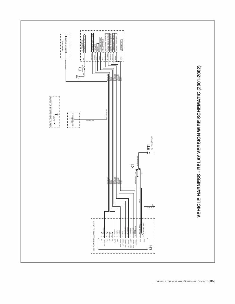
Vehicle Harness Wire Schematic (2001-02) 35
VE
HIC
LE
HA
RN
ES
S -
RE
LA
Y V
ER
SIO
N W
IRE
SC
HE
MA
TIC
(20
01-2
002)
N/A
VD
C F
US
ED
N/A
N/A
N/A
FLO
AT
LIF
T
RIG
HT
AN
GLE
LEF
T A
NG
LE
LEF
T B
OX
RE
T.
LEF
T B
OX
EX
T.
RIG
HT
BO
X R
ET.
RIG
HT
BO
X E
XT.
PU
MP
SO
L.
PO
S
NE
G
16 15 14 13 12 11 10 9 8 7 6 5 4 3 2
PIN
K/B
LAC
K
OR
AN
GE
WH
ITE
GR
EE
N
BLU
E
BLU
E/B
LAC
K
BLU
E/W
HIT
E
RE
D/B
LAC
K
RE
D/W
HIT
EB
RO
WN
RE
D #
6 A
WG
BLA
CK
#6
AW
G1
PIN
K/B
LAC
KO
RA
NG
EW
HIT
EG
RE
EN
BLU
EB
LUE
/BLA
CK
BLU
E/W
HIT
ER
ED
/BLA
CK
RE
D/W
HIT
EB
RO
WN
BLA
CK
RE
D
BLACK
M1
A1
SE
E P
LOW
HA
RN
ES
S W
IRE
SC
HE
MAT
IC
A2
BR
OW
N/W
HIT
EA
10
PU
MP
RE
LAY
BT
1V
EH
ICLE
BAT
TE
RY
K1
BR
OW
N/W
HIT
E
BLA
CK
(18
AW
G)
(10)
SW
ITC
HE
D 1
2 V
DC
(4)
FLO
AT
(8)
LIF
T
(11)
RIG
HT
AN
GLE
(12)
LE
FT
AN
GLE
(6)
LEF
T B
OX
RE
TR
AC
T
(5)
RIG
HT
BO
X E
XT
EN
D
(2)
RIG
HT
BO
X R
ET
RA
CT
(1)
RIG
HT
BO
X E
XT
EN
D
(9)
PU
MP
SO
LEN
OID
12-P
IN M
ATR
IX
PIN
K/B
LAC
K
OR
AN
GE
WH
ITE
GR
EE
N
BLU
E
BLU
E/B
LAC
K
BLU
E/W
HIT
E
RE
D/B
LAC
K
RE
D/W
HIT
E
BR
OW
N
(3)
SW
ITC
H 1
2 V
OLT
+R
ED
(7)
GR
OU
ND
BLA
CK
PIN
K/B
LAC
KO
RA
NG
EW
HIT
EG
RE
EN
BLU
EB
LUE
/BLA
CK
BLU
E/W
HIT
ER
ED
/BLA
CK
RE
D/W
HIT
EB
RO
WN
BLA
CK
A9
RE
DF
US
E 1
0 A
MP
Vcc
F1
(1)
RE
LAY
GR
OU
ND
GR
EE
N/Y
ELL
OW
GR
EE
N/Y
ELL
OW
BLACK/WHITE
2-P
IN M
ATR
IX
(RE
LAY
).2
50 R
EC
EP
TIC
LE
NO
TE
: ALL
GR
OU
ND
S H
AV
E B
LAC
K W
IRE
BLA
CK

36 Diagram - On/Off Switch Leads & Ground
ON
/OF
F S
WIT
CH
LE
AD
S &
GR
OU
ND
LE
AD
(20
01-2
002)
FO
R B
LIZ
ZA
RD
RE
LAY
HA
RN
ES
S W
HE
N U
SIN
G A
CO
NT
RO
L S
TAT
ION
WIT
H A
SIN
GLE
PO
WE
R S
WIT
CH
NO
T D
RA
WN
TO
SC
ALE
UN
LES
S O
TH
ER
WIS
E S
PE
CIF
IED
ALL
DIM
EN
SIO
NS
IN IN
CH
ES
TO C
ON
TR
OL
“AM
P”
CO
NN
EC
TOR
(2)
PIN
PO
WE
R C
ON
NE
CTO
RW
ITH
“M
OL
EX
” M
AL
E T
ER
MIN
AL
PIN
C
OL
OR
FU
NC
TIO
NA
WG
NO
.
1G
RE
EN
/YE
LLO
WR
ELA
Y G
RO
UN
D (
FR
OM
SW
ITC
H)
182
GR
EE
N/Y
ELL
OW
RE
LAY
GR
OU
ND
(F
RO
M S
WIT
CH
)18
EN
D V
IEW
LOO
KIN
G A
TC
ON
NE
CTO
R
1 2
“MO
LE
X”
FR
EE
HA
NG
ING
RE
CE
PTA
CL
E.0
93 (
2) P
IN P
OW
ER
CO
NN
EC
TOR
WIT
H “
MO
LE
X”
FE
MA
LE
TE
RM
INA
L
PIN
C
OL
OR
FU
NC
TIO
NA
WG
NO
.
1G
RE
EN
/YE
LLO
WR
ELA
Y G
RO
UN
D (
FR
OM
VE
H. H
AR
NE
SS
)18
2G
RE
EN
/YE
LLO
WR
ELA
Y G
RO
UN
D (
FR
OM
#10
RIN
G T
ER
M.)
18
1 2E
ND
VIE
WLO
OK
ING
AT
CO
NN
EC
TOR
GR
EE
N/Y
ELL
OW
12"
LON
G
GR
EE
N/Y
ELL
OW
12"
LON
G.2
50 R
EC
EP
TAC
LE
.250
RE
CE
PTA
CLE
SW
ITC
H L
EA
DS
P/N
621
27
GR
OU
ND
LE
AD
P/N
621
26GR
EE
N/Y
ELL
OW
24"
LON
G
#10
RIN
G T
ER
MIN
AL
GR
OU
ND
TO
VE
HIC
LE
VE
HIC
LE H
AR
NE
SS
SE
E D
IAG
RA
M O
N P
AG
E 3
4
DP
DT
TO
GG
LE S
WIT
CH
P/N
620
38N
OT
E: S
EE
INS
TALL
ATIO
NIN
ST
RU
CT
ION
ON
PA
GE
11.

TSB - Ford Blocker Beam™ 37
This Technical Service Bulletin (TSB) has been issued for all 2001 Model year Ford Super Duty F-250, F-350, F-450, and F-550 snowplowundercarriage installations. These vehicles (starting in October 2000) contain a front BLOCKER BEAM™ as standard equipment.This beam is designed to prevent a car from sliding beneath the higher riding front truck bumper during a frontal collision.
WARNING: Removal of the Blocker Beam™, without the installation of the snowplow undercarriage, may affect air bagdeployment in a crash. The vehicle should not be operated without either the snowplow undercarriage or the BlockerBeam™ in place. Should a Blocker Beam™ be removed from the front of a Ford Super Duty truck to accommodatethe installation of a snowplow, it should be tagged, packaged and supplied to the customer with the completed vehicle,along with reinstallation instructions (see diagram).
1. To install your Blizzard undercarriage on a Ford F-250, F-350, F-450 or F-550 vehicle, first tag the BLOCKER BEAM™ that is to beremoved. This tag will serve as a reminder to re-install the beam should the customer ever remove the snowplow undercarriage.Note: Tags are being added to all applicable undercarriage kits as a running change. Contact Customer Service toll free at 1-888-680-8600 should you wish to receive tags for undercarriages in inventory.
2. Loosen the Blocker Beam™ from both SPRING BRACKETS by removing the three fasteners at each end of the Blocker Beam™.Re-attach the fasteners to either end of the Blocker Beam™ for storage.
TECHNICAL SERVICE BULLETINAll Blizzard Snowplows
Issued November 27, 2000
BLOCKER BEAM™
REMOVE THESEFASTENERS
SPRING BRACKET
DRIVER’S SIDE ILLUSTRATION
95 AIRPARK BOULEVARD CALUMET, MI 49913 [906] 482-5555 [906] 482-5445 FAX1183-11-00
WARNING: Replace Ford® Blocker Beam™ using original vehiclehardware should you remove your snowplow undercarriage.Failure to replace Blocker Beam™, without the installation of asnowplow undercarriage, may affect airbag deployment in acrash. The vehicle should not be operated without either thesnowplow undercarriage or Blocker Beam™ in place.
Note: This notice affects 2001 Model year Ford® Super Duty F-250, F-350,F-450 and F-550 vehicles.
1185-11-00
95 AIRPARK BOULEVARD CALUMET, MI 49913 [906] 482-5555 [906] 482-5445 FAX
BLOCKER BEAM™ TAG
PUSH BEAM LABEL
BLZ 103195 AIRPARK BOULEVARD CALUMET, MI 49913 [906] 482-5555 [906] 482-5445 FAX
WARNING: Replace Ford® Blocker Beam™ using original vehiclehardware should you remove your snowplow undercarriage.Failure to replace Blocker Beam™, without the installation of asnowplow undercarriage, may affect airbag deployment in acrash. The vehicle should not be operated without either thesnowplow undercarriage or Blocker Beam™ in place.
Note: This notice affects 2001 Model year Ford® Super Duty F-250, F-350,F-450 and F-550 vehicles.

38 1988-91 Ford F-150 Undercarriage
1988-1991 Ford F-150 Series Undercarriage
12-1/2"
WARNING: Most new trucks areequipped with driver and passenger’s
side air bags. DO NOT remove, disable, orreposition any sensory equipment related tothe safe operation of the air bags.
ALWAYS follow the vehicle manufacturer’srecommendations for installing snowplowingequipment.
Failure to comply with the above warning mayresult in serious injury or death.
CAUTION: If your vehicle is equippedwith oversize tires, they may come
into contact with the undercarriage hangerplates when turning the vehicle.
The problem may be resolved by setting thesteering stops on the vehicle. If this does notcorrect the problem, the original tires will needto be installed on the vehicle.
The recommended push beam height for allundercarriage assemblies is 12-1/2" from thecenter of the push beam to level ground. DO NOTexceed 14" in height for any undercarriage.
1. Begin the undercarriage assembly by removing the front bumper on thevehicle. There are two mounting plates with four M12-1.75 x 45 flangedhex head screws and M12-1.75 nuts to be removed. These are locatedon the inside of the truck frame rail.
2. Match the holes in each of the HANGER PLATES to those located on theoutside of the truck frame rail. Insert one 5/8"-11 x 4" bolt through the rearhole in the hanger plate and truck frame rail. Position one 5/8"-11 top lockingnut with 14" welded stock and washer inside of the truck frame rail on thedriver’s side and fasten. Note: The passenger’s side receives a 5/8"-11top lock nut and washer. No welded stock is necessary since the bolt iseasily accessible. Loosely attach all nuts until all undercarriage platesare positioned.
3. Align the front mounting hole on the plate with the hole in the truck frame.Fasten the plate to the vehicle with one 5/8"-11 x 2-3/4" bolt, washer andtop lock nut.
4. Complete the hanger plate installation by positioning one 5/8"-11 x 4-1/2"bolt through the middle mounting hole in the plate. Secure the screw withone 5/8" top lock nut and washer.
5. Repeat steps #2 through #4 for the opposite hanger plate. Note: If yourvehicle is equipped with oversize tires, the steering stop may need to beadjusted to prevent the tires from hitting the hanger plates.
6. Mount the PUSH BEAM to the hanger plates using eight 1/2"-13 x 1-1/2"bolts and 1/2"-13 top lock nuts. Note: The proper height for the push beamis approximately 12-1/2" from the ground to the center of the push beam.
7. Once all of the undercarriage plates have been positioned and the properpush beam height is set, proceed to tighten all top lock nuts. Referencethe chart on page 4 for maximum bolt torque.
8. Replace the bumper using the existing hardware.
9. Position the LIGHT TOWER into the accepting pockets on the push beamand tighten using two 1/2"-13 x 1-1/4" bolts with washers. Secure eachbolt with a 1/2" top locking nut. Mount each PLOW HEADLIGHT to the lighttower with the hardware kit provided.
Complete the assembly by plugging the connectors from the lights into the connectors on the vehicle wire harness.

1988-91 Ford F-150 Undercarriage 39
Ref. Part Qty. Part DescriptionNo. No.
1A 31074 1 1988-1991 Ford F-150 Series Undercarriage Assembly (Nos. 1 - 14)
1 31075 1 41-5/8" Push Beam (1988-91 Ford F-150)
1L 61128 1 1-1/2" x 9" Push Beam Decal
2 31079 1 Passenger’s Side Hanger Plate (1988-91 Ford F-150)
3 31080 1 Driver’s Side Hanger Plate (1988-91 Ford F-150)
4 39034 1 Light Tower, Round Mounting Tube - Model 760LD
5 61057 2 1/2"-13 x 1-1/4" Grade 8 YZ Hex Head Cap Screw
6 61026 2 1/2", 1-1/16" O.D., 17/32" I.D. YZ SAE Mil-Carb High-Strength Washer
7 61020 10 1/2"-13 Grade C Z Top Lock Nut
8 61055 8 1/2"-13 x 1-1/2" Grade 8 YZ Hex Head Cap Screw
9 61061 2 5/8"-11 x 2-3/4" Grade 8 YZ Hex Head Cap Screw
10 61064 6 5/8", 1-5/16" O.D., 21/32" I.D., YZ SAE Mil-Carb High-Strength Washer
11 61063 5 5/8"-11 Grade C Z Top Lock Nut
12 61065 2 5/8"-11 x 4-1/2" Grade 8 YZ Hex Head Cap Screw
13 61155 2 5/8"-11 x 4" Grade 8 YZ Hex Head Cap Screw
14 61161 1 5/8"-11 Grade C Z Top Lock Nut with Welded 14" Square Stock
N/A 61159 1 1988-1991 Ford F-150 Series Undercarriage Hardware Kit - Kit Includes: Nos. 5 - 14
1A1
7
212 13
10
11
10 11
8
8
9
4
7
7
5
6
1L
6
7
57
8
8
8
12
7
9
1011
1011
3
1014
13
Note: The reference numbers listed identify parts shown in the illustration above. These numbers are specific to this illustration only and do not correspond with otherdiagrams issued. Always review the part number given for proper component identification.
1 9 8 8 - 1 9 9 1 F O R D F - 1 5 0 S E R I E S U N D E R C A R R I AG E PA R T S L I S T

40 1987-91 Ford F-250 & F-350 Undercarriage
1. Begin the undercarriage assembly by removing the front bumper of thevehicle. There are two mounting plates with four M12-1.75 x 45 flangedhex head screws and M12-1.75 nuts to be removed. These are locatedon the inside of the truck frame rail.
2. Match the holes in each of the HANGER PLATES to those located on theoutside of the truck frame rail. Insert one 5/8"-11 x 4" bolt through the rearhole in the hanger plate and truck frame rail. Position one 5/8"-11 top lockingnut with 14" welded stock inside of the truck frame rail and fasten.Note: Loosely attach all nuts until all undercarriage plates are positioned.
3. Position the hanger plate cut-outs over the spring shackle bolt and leafspring clamp mounts. Align the front mounting hole on the plate with thehole in the truck frame. Fasten the plate to the vehicle with one 5/8"-11 x2-3/4" bolt and top lock nut.
4. Complete the hanger plate installation by positioning one 5/8"-11 x 4-1/2"bolt through the middle mounting hole in the plate. Secure the screw withone 5/8" top lock nut.
5. Repeat steps #2 through #4 for the opposite hanger plate. Note: If yourvehicle is equipped with oversize tires, the steering stop may need to beadjusted to prevent the tire from hitting the hanger plate.
6. Mount the PUSH BEAM to the hanger plates using eight 1/2"-13 x 1-1/2"bolts and 1/2"-13 top lock nuts. Note: The proper height for the push beamis approximately 12-1/2" from the ground to the center of the push beam.
7. Once all of the undercarriage plates have been positioned and the properpush beam height is set, proceed to tighten all top lock nuts. Referencethe chart on page 4 for maximum bolt torque.
8. Replace the bumper using the existing hardware.
9. Position the LIGHT TOWER into the accepting pockets on the push beamand tighten using two 1/2"-13 x 1-1/4" bolts with washers. Secure eachbolt with a 1/2" top locking nut. Mount each PLOW HEADLIGHT to the lighttower with the hardware kit provided.
Complete the assembly by plugging the connectors from the lights into the connectors on the vehicle wire harness.
1987-1991 Ford F-250 & F-350 Series Undercarriage
12-1/2"
WARNING: Most new trucks areequipped with driver and passenger’s
side air bags. DO NOT remove, disable, orreposition any sensory equipment related tothe safe operation of the air bags.
ALWAYS follow the vehicle manufacturer’srecommendations for installing snowplowingequipment.
Failure to comply with the above warning mayresult in serious injury or death.
CAUTION: If your vehicle is equippedwith oversize tires, they may come
into contact with the undercarriage hangerplates when turning the vehicle.
The problem may be resolved by setting thesteering stops on the vehicle. If this does notcorrect the problem, the original tires will needto be installed on the vehicle.
The recommended push beam height for allundercarriage assemblies is 12-1/2" from thecenter of the push beam to level ground. DO NOTexceed 14" in height for any undercarriage.

1987-91 Ford F-250 & F-350 Undercarriage 41
Ref. Part Qty. Part DescriptionNo. No.
1A 31041 1 1987-1991 Ford F-250 & F-350 Series Undercarriage Assembly (Nos. 1-14)
1 31042 1 Passenger’s Side Hanger Plate (1987-91 Ford F-250 & F-350)
2 31045 1 41-5/8" Push Beam (1987-91 Ford F-250 & F-350)
2L 61085 1 2-1/8" x 13-1/8" Push Beam Decal
3 31043 1 Driver’s Side Hanger Plate (1987-91 Ford F-250 & F-350)
4 39032 1 Light Tower, Round Mounting Tube
5 61061 2 5/8"-11 x 2-3/4" Grade 8 YZ Hex Head Cap Screw
6 61065 2 5/8"-11 x 4-1/2" Grade 8 YZ Hex Head Cap Screw
7 61155 2 5/8"-11 x 4" Grade 8 YZ Hex Head Cap Screw
8 61161 2 5/8"-11 Grade C Z Top Lock Nut with Welded 14" Square Stock
9 61063 4 5/8"-11 Grade C Z Top Lock Nut
10 61055 8 1/2"-13 x 1-1/2" Grade 8 YZ Hex Head Cap Screw
11 61020 10 1/2"-13 Grade C Z Top Lock Nut
12 61057 2 1/2"-13 x 1-1/4" Grade 8 YZ Hex Head Cap Screw
13 61026 2 1/2", 1-1/16" O.D., 17/32" I.D. YZ SAE Mil-Carb High-Strength Washer
14 61064 6 5/8", 1-5/16" O.D., 21/32" I.D., YZ SAE Mil-Carb High-Strength Washer
N/A 61157 1 1987-1991 Ford F-250 & F-350 Series Undercarriage Hardware Kit - Kit Includes: Nos. 5 - 14
1
1A
8
76
510
4
12
11
2
11
2L
11
10
5
3
6
79
8
9
13
14
14
14
Note: The reference numbers listed identify parts shown in the illustration above. These numbers are specific to this illustration only and do not correspond with otherdiagrams issued. Always review the part number given for proper component identification.
1 9 8 7 - 1 9 9 1 F O R D F - 2 5 0 & F - 3 5 0 S E R I E S U N D E R C A R R I AG E PA R T S L I S T

42 1992-96 Ford F-150 Undercarriage
1992-1996 Ford F-150 Series Undercarriage
12-1/2"
WARNING: Most new trucks areequipped with driver and passenger’s
side air bags. DO NOT remove, disable, orreposition any sensory equipment related tothe safe operation of the air bags.
ALWAYS follow the vehicle manufacturer’srecommendations for installing snowplowingequipment.
Failure to comply with the above warning mayresult in serious injury or death.
CAUTION: If your vehicle is equippedwith oversize tires, they may come
into contact with the undercarriage hangerplates when turning the vehicle.
The problem may be resolved by setting thesteering stops on the vehicle. If this does notcorrect the problem, the original tires will needto be installed on the vehicle.
The recommended push beam height for allundercarriage assemblies is 12-1/2" from thecenter of the push beam to level ground. DO NOTexceed 14" in height for any undercarriage.
1. Begin the assembly by removing the front bumper on the vehicle. Thereare four bolts with nuts that need to be removed. These are located onthe inside of the TRUCK FRAME RAIL.
2. Remove the PLASTIC BUMPER FASCIA mounted to the bottom of thebumper. Note: The bumper fascia will need to be permanently removed ornotched to accommodate the undercarriage assembly.
3. Align the REAR MOUNT HOLES on the UNDERCARRIAGE with thebrackets located under each truck frame rail. Note: Use a hydraulic floorjack to help facilitate the installation procedure. Secure the push beamassembly to the truck with four 1/2"-13 x 1-1/2" bolts, double washers andtop lock nuts.
4. Next, align the FRONT UNDERCARRIAGE MOUNT HOLES with the holeson the outside of the truck frame rail. Use 1/2"-13 x 1-1/2" bolts with doublewashers and top lock nuts to secure these mount points.
5. Replace the bumper using the existing hardware.
6. Position the LIGHT TOWER into the accepting pockets on the push beamand tighten using two 1/2"-13 x 1-1/4" bolts with washers. Secure eachbolt with a 1/2" top locking nut. Mount each PLOW HEADLIGHT to thelight tower with the hardware kit provided.
Complete the assembly by plugging the connectors from the lights into the connectors on the vehicle wire harness.

1992-96 Ford F-150 Undercarriage 43
Ref. Part Qty. Part DescriptionNo. No.
1A 31056 1 1992-1996 Ford F-150 Series Undercarriage Assembly (Nos.1 - 6)
1 31057 1 41-1/2" Push Beam (1992-1996 Ford F-150)
1L 61128 1 1-1/2" x 9" Push Beam Decal
2 39034 1 Light Tower, Round Mounting Tube - Model 760LD
3 61057 2 1/2"-13 x 1-1/4" Grade 8 YZ Hex Head Cap Screw
4 61026 14 1/2", 1-1/16" O.D., 17/32" I.D. YZ SAE Mil-Carb High-Strength Washer
5 61020 8 1/2"-13 Grade C Z Top Lock Nut
6 61055 6 1/2"-13 x 1-1/2" Grade 8 YZ Hex Head Cap Screw
N/A 61208 1 1992-1996 Ford F-150 Series Undercarriage Hardware Kit - Kit Includes: Nos. 3 - 6
Note: The reference numbers listed identify parts shown in the illustration above. These numbers are specific to this illustration only and do not correspond with otherdiagrams in the manual. Always review the part number given for proper component identification.
1 9 9 2 - 1 9 9 6 F O R D F - 1 5 0 S E R I E S U N D E R C A R R I AG E PA R T S L I S T
2
3
4
5
4
5
1L
1A1
6 4 4
5
6
5
4
4
6
3
4
5
4

44 1992-98 Ford F-250 & F-350 Undercarriage
1992-1998 Ford F-250 & F-350 Series Undercarriage
12-1/2"
WARNING: Most new trucks areequipped with driver and passenger’s
side air bags. DO NOT remove, disable, orreposition any sensory equipment related tothe safe operation of the air bags.
ALWAYS follow the vehicle manufacturer’srecommendations for installing snowplowingequipment.
Failure to comply with the above warning mayresult in serious injury or death.
CAUTION: If your vehicle is equippedwith oversize tires, they may come
into contact with the undercarriage hangerplates when turning the vehicle.
The problem may be resolved by setting thesteering stops on the vehicle. If this does notcorrect the problem, the original tires will needto be installed on the vehicle.
The recommended push beam height for allundercarriage assemblies is 12-1/2" from thecenter of the push beam to level ground. DO NOTexceed 14" in height for any undercarriage.
1. Begin the assembly by removing the four nuts from the FRONT BUMPERMOUNT. Remove the bumper.
2. Position the DRIVER’S SIDE HANGER PLATE on the outside of the truckframe rail. Attach one 5/8"-11 x 1-3/4" bolt through the front mount onthe hanger plate and truck frame rail. Secure the bolt with one 5/8" washerand top lock nut on the inside of the frame rail. Note: Use the opening atthe end of the frame rail to access the nut and washer.
3. Position one 5/8"-11 x 3-1/4" bolt through the rear mount on the hangerplate and truck frame rail. Secure the bolt with one 5/8" washer and top lock nut on the inside of the frame rail. Note: Use an original openingcut into the frame rail behind the mounting hole to position the nut andwasher.
4. Position one 5/8"-11 x 2-3/4" bolt through the middle mount on the hangerplate and truck frame rail. Secure the bolt with one 5/8" washer and toplock nut on the inside of the frame rail. Note: Use an original opening onthe inside of the truck frame rail opposite of the mount to position the nutand washer.
5. Repeat all three procedures above to securely mount the PASSENGER’SSIDE HANGER PLATE.
6. Mount the PUSH BEAM to each hanger plate using four 1/2"-13 x 1-1/2"bolts and top lock nuts. Note: The proper height for the push beam isapproximately 12-1/2" from the ground to the center of the beam.
7. Once all of the undercarriage plates have been positioned and the properpush beam height is set, proceed to tighten all top lock nuts. Referencethe chart on page 4 for maximum bolt torque.
8. Position the LIGHT TOWER into the accepting pockets on the push beamand tighten using two 1/2"-13 x 1-1/4" bolts with washers. Secure eachbolt with a 1/2" top lock nut. Mount each PLOW HEADLIGHT to the lighttower with the hardware kit provided.
Complete the assembly by plugging the connectors from the lights into the connectors on the vehicle wire harness.

1992-98 Ford F-250 & F-350 Undercarriage 45
Ref. Part Qty. Part DescriptionNo. No.
1A 31036 1 1992-1998 Ford F-250 & F-350 Series Undercarriage Assembly (Nos.1-13)
1 31013 1 Passenger’s Side Hanger Plate (1992-1998 Ford F-250 & F-350)
2 31019 1 40-5/8" Push Beam (1992-1998 Ford F-250 & F-350)
2L 61085 1 2-1/8" x 13-1/8" Push Beam Decal
3 31011 1 Driver’s Side Hanger Plate (1992-1998 Ford F-250 & F-350)
4 39032 1 Light Tower, Round Mounting Tube
5 61060 2 5/8"-11 x 1-3/4" Grade 8 YZ Hex Cap Screw
6 61061 2 5/8"-11 x 2-3/4" Grade 8 YZ Hex Cap Screw
7 61062 2 5/8"-11 x 3-1/4" Grade 8 YZ Hex Cap Screw
8 61064 6 5/8", 1-5/16" O.D., 21/32" I.D., YZ SAE Mil-Carb High-Strength Washer
9 61063 6 5/8"-11 Grade C Z Top Lock Nut
10 61055 8 1/2"-13 x 1-1/2" Grade 8 YZ Hex Head Cap Screw
11 61020 10 1/2"-13 Grade C Z Top Lock Nut
12 61057 2 1/2"-13 x 1-1/4" Grade 8 YZ Hex Head Cap Screw
13 61026 2 1/2", 1-1/16" O.D., 17/32" I.D. YZ SAE Mil-Carb High-Strength Washer
N/A 61080 1 1992-1998 Ford F-250 & F-350 Series Undercarriage Hardware Kit - Kit Includes: Nos. 5 - 13
1
2
3
4
5 6 7
5
6
7
8
8
9
9
10
10
11
11
12
13
11
1A
2L
Note: The reference numbers listed identify parts shown in the illustration above. These numbers are specific to this illustration only and do not correspond with otherdiagrams in the manual. Always review the part number given for proper component identification.
1 9 9 2 - 1 9 9 8 F O R D F - 2 5 0 & F - 3 5 0 S E R I E S U N D E R C A R R I AG E PA R T S L I S T

46 1998-02 Ford F-150 Undercarriage
1998-2002 Ford F-150 Series Undercarriage
12-1/2"
WARNING: Most new trucks areequipped with driver and passenger’s
side air bags. DO NOT remove, disable, orreposition any sensory equipment related tothe safe operation of the air bags.
ALWAYS follow the vehicle manufacturer’srecommendations for installing snowplowingequipment.
Failure to comply with the above warning mayresult in serious injury or death.
CAUTION: If your vehicle is equippedwith oversize tires, they may come
into contact with the undercarriage hangerplates when turning the vehicle.
The problem may be resolved by setting thesteering stops on the vehicle. If this does notcorrect the problem, the original tires will needto be installed on the vehicle.
The recommended push beam height for allundercarriage assemblies is 12-1/2" from thecenter of the push beam to level ground. DO NOTexceed 14" in height for any undercarriage.
1. Begin the assembly by removing the front bumper on the vehicle.
2. Remove the PLASTIC BUMPER FASCIA mounted to the bottom of thebumper. Note: The bumper fascia will need to be permanently removedor notched to accommodate the undercarriage assembly. Also, shouldyour vehicle have frame rail mounted TOW HOOKS, these will need to beremoved to facilitate the undercarriage installation. The push beamassembly will not install properly with the tow hooks in place.
3. Align the front mount holes on the UNDERCARRIAGE (at each end of thePUSH BEAM) with the tow hook mount holes on the TRUCK FRAME RAIL.Note: Use a hydraulic floor jack to help facilitate the installation procedure.Secure the push beam assembly to the truck with four 9/16"-12 x 1-1/2"bolts, double washers and top lock nuts. Note: Loosely attach all nuts untilthe remaining hardware is in position.
4. Next, align the REAR UNDERCARRIAGE MOUNT ARMS with the holeslocated in the middle of the TRUCK FRAME CROSSMEMBER. Note: Thecrossmember contains two rubber access caps. Remove these caps togain access to the interior of the crossmember. Attach a thin gauge wireto each 1/2"-13 x 1-1/2" bolt and feed the wire through each crossmemberaccess hole to the middle mount holes. Pull the bolt through the hole inthe crossmember and undercarriage mount arms. Secure each bolt withone 1/2" washer and top lock nut. Replace rubber access caps.
5. Finish securing the undercarriage to the truck frame by placing two 1/2"-13 x 1-1/2" bolts through the bottom of the undercarriage at the towhook mount holes located under the truck frame rail. Secure each bolt withone 1/2" washer and top lock nut.
6. Once the undercarriage has been positioned and all hardware is in place,proceed to tighten all top lock nuts. Reference the chart on page 4 formaximum bolt torque.
7. Replace the bumper using the existing hardware.
8. Position the LIGHT TOWER into the accepting pockets on the push beamand tighten using two 1/2"-13 x 1-1/4" bolts with washers. Secure eachbolt with a 1/2" top locking nut. Mount each PLOW HEADLIGHT to thelight tower with the hardware kit provided.
Complete the assembly by plugging the connectors from the lights into the connectors on the vehicle wire harness.

1998-02 Ford F-150 Undercarriage 47
Ref. Part Qty. Part DescriptionNo. No.
1A 31046 1 1998-2002 Ford F-150 Series Undercarriage Assembly (Nos.1 - 9)
1 31084 1 37" Push Beam (1998-2002 Ford F-150)
1L 61128 1 1-1/2" x 9" Push Beam Decal
2 39034 1 Light Tower, Round Mounting Tube - Model 760LD
3 61057 2 1/2"-13 x 1-1/4" Grade 8 YZ Hex Head Cap Screw
4 61026 6 1/2", 1-1/16" O.D., 17/32" I.D. YZ SAE Mil-Carb High-Strength Washer
5 61020 6 1/2"-13 Grade C Z Top Lock Nut
6 61056 4 9/16"-12 x 1-1/2" Grade 8 YZ Hex Head Cap Screw
7 61027 8 1/2", 1-3/8" O.D., 9/16" I.D. YZ USS Mil-Carb High-Strength Washer
8 61058 4 9/16"-12 Grade C Top Lock Nut
9 61055 4 1/2"-13 x 1-1/2" Grade 8 YZ Hex Head Cap Screw
N/A 61193 1 1998-2002 Ford F-150 Series Undercarriage Hardware Kit - Kit Includes: Nos. 3 - 9
Note: The reference numbers listed identify parts shown in the illustration above. These numbers are specific to this illustration only and do not correspond with otherdiagrams in the manual. Always review the part number given for proper component identification.
1 9 9 8 - 2 0 0 2 F O R D F - 1 5 0 S E R I E S U N D E R C A R R I AG E PA R T S L I S T
1A1
1L
2
3
4
5
6 6
6
6
7
7
77
77
7
8
8
8
8
7
9
9
9
9
45
45
4
5
45
4
5
3

48 1999-02 Ford Expedition Undercarriage
1999-2002 Ford Expedition Undercarriage
12-1/2"
WARNING: Most new trucks areequipped with driver and passenger’s
side air bags. DO NOT remove, disable, orreposition any sensory equipment related tothe safe operation of the air bags.
ALWAYS follow the vehicle manufacturer’srecommendations for installing snowplowingequipment.
Failure to comply with the above warning mayresult in serious injury or death.
CAUTION: If your vehicle is equippedwith oversize tires, they may come
into contact with the undercarriage hangerplates when turning the vehicle.
The problem may be resolved by setting thesteering stops on the vehicle. If this does notcorrect the problem, the original tires will needto be installed on the vehicle.
The recommended push beam height for allundercarriage assemblies is 12-1/2" from thecenter of the push beam to level ground. DO NOTexceed 14" in height for any undercarriage.
1. Begin the assembly by removing the front bumper on the vehicle.
2. Remove the PLASTIC BUMPER FASCIA mounted to the bottom of thebumper. Note: The bumper fascia will need to be permanently removedor notched to accommodate the undercarriage assembly. Also, shouldyour vehicle have frame rail mounted TOW HOOKS, these will need to beremoved to facilitate the undercarriage installation. The push beamassembly will not install properly with the tow hooks in place.
3. Align the front mount holes on the UNDERCARRIAGE (at each end of thePUSH BEAM) with the tow hook mount holes on the TRUCK FRAME RAIL.Note: Use a hydraulic floor jack to help facilitate the installation procedure.Secure the push beam assembly to the truck with four 9/16"-12 x 1-1/2"bolts, double washers and top lock nuts. Note: Loosely attach all nuts untilthe remaining hardware is in position.
4. Next, align the REAR UNDERCARRIAGE MOUNT ARMS with the holeslocated in the middle of the TRUCK FRAME CROSSMEMBER. Note: Thecrossmember contains two rubber access caps. Remove these caps togain access to the interior of the crossmember. Attach a thin gauge wireto each 1/2"-13 x 2-3/4" bolt and feed the wire through each crossmemberaccess hole to the middle mount holes. Pull the bolt through the hole inthe crossmember and undercarriage mount arms. Secure each bolt withone 1/2" washer and top lock nut. Replace rubber access caps.
5. Finish securing the undercarriage to the truck frame by placing two 1/2"-13 x 1-1/2" bolts through the bottom of the undercarriage at the towhook mount holes located under the truck frame rail. Secure each bolt withone 1/2" washer and top lock nut.
6. Once the undercarriage has been positioned and all hardware is in place,proceed to tighten all top lock nuts. Reference the chart on page 4 formaximum bolt torque.
7. Replace the bumper using the existing hardware.
8. Position the LIGHT TOWER into the accepting pockets on the push beamand tighten using two 1/2"-13 x 1-1/4" bolts with washers. Secure eachbolt with a 1/2" top locking nut. Mount each PLOW HEADLIGHT to thelight tower with the hardware kit provided.
Complete the assembly by plugging the connectors from the lights into the connectors on the vehicle wire harness.

1999-02 Ford Expedition Undercarriage 49
Ref. Part Qty. Part DescriptionNo. No.
1A 31085 1 1999-2002 Ford Expedition Undercarriage Assembly (Nos.1 - 10)
1 31069 1 36-7/8" Push Beam (1999-2002 Ford Expedition)
1L 61128 1 1-1/2" x 9" Push Beam Decal
2 39034 1 Light Tower, Round Mounting Tube - Model 760LD
3 61057 2 1/2"-13 x 1-1/4" Grade 8 YZ Hex Head Cap Screw
4 61026 6 1/2", 1-1/16" O.D., 17/32" I.D. YZ SAE Mil-Carb High-Strength Washer
5 61020 6 1/2"-13 Grade C Z Top Lock Nut
6 61056 4 9/16"-12 x 1-1/2" Grade 8 YZ Hex Head Cap Screw
7 61027 8 1/2", 1-3/8" O.D., 9/16" I.D. YZ USS Mil-Carb High-Strength Washer
8 61058 4 9/16"-12 Grade C Top Lock Nut
9 61055 2 1/2"-13 x 1-1/2" Grade 8 YZ Hex Head Cap Screw
10 61276 2 1/2"-13 x 2-3/4" Grade 8 YZ Hex Head Cap Screw
N/A 61270 1 1999-2002 Ford Expedition Undercarriage Hardware Kit - Kit Includes: Nos. 3 - 10
10
1A1
1L
2
3
4
5
6 6
6
6
7
7
77
77
7
8
8
8
8
7
9
10
9
45
45
4
5
45
4
5
3
Note: The reference numbers listed identify parts shown in the illustration above. These numbers are specific to this illustration only and do not correspond with otherdiagrams in the manual. Always review the part number given for proper component identification.
1 9 9 9 - 2 0 0 2 F O R D E X P E D I T I O N U N D E R C A R R I AG E PA R T S L I S T

50 1999-02 Ford F-250 & F-350 Undercarriage
1999-2002 Ford F-250 & F-350 Series Undercarriage
12-1/2"
WARNING: Most new trucks areequipped with driver and passenger’s
side air bags. DO NOT remove, disable, orreposition any sensory equipment related tothe safe operation of the air bags.
ALWAYS follow the vehicle manufacturer’srecommendations for installing snowplowingequipment.
Failure to comply with the above warning mayresult in serious injury or death.
CAUTION: If your vehicle is equippedwith oversize tires, they may come
into contact with the undercarriage hangerplates when turning the vehicle.
The problem may be resolved by setting thesteering stops on the vehicle. If this does notcorrect the problem, the original tires will needto be installed on the vehicle.
The recommended push beam height for allundercarriage assemblies is 12-1/2" from thecenter of the push beam to level ground. DO NOTexceed 14" in height for any undercarriage.
1. Begin the undercarriage assembly by removing the front bumper of thevehicle. There are four 1/2"-13 x 1-3/4" acorn head bolts with 1/2"washers, two nut plates and two bumper shim plates to remove.Note: The bumper shim plate prohibits the proper mounting bolts frombeing installed. Either discard the plate or increase the size of the holeslocated on the front.
Note: If your vehicle is equipped with a Blocker Beam™, review theTechnical Service Bulletin on page 37.
2. Attach each HANGER PLATE (2) to the truck frame rails using two 1/2"-13 x 1-1/4" bolts and washers. Secure all bolts using a 1/2"-13 toplock nut. Note: Loosely attach all nuts until all undercarriage plates arepositioned.
3. Rest both ZEE BRACKETS on the truck frame rail and fasten two 1/2"-13 x 1-1/2" bolts with washers to the hanger plate. Loosely tighten1/2"-13 top lock nuts to all bolts.
4. Install one 9/16"-12 x 1-1/2" bolt with a 9/16" washer inside of the truckframe bumper bracket to the side zee bracket ear. Loosely thread a9/16"-12 top lock nut to each bolt.
5. Mount the PUSH BEAM to the hanger plate using two 1/2"-13 x 1-1/2"bolts and top lock nuts. Note: The proper height for the push beam isapproximately 12-1/2" from the ground to the center of the beam.
6. Remove the M12-1.75 x 35 (10.9 Gr.) rear spring shackle bolt withtabbed nut on the outside of the frame rail. Position each HANGERSUPPORT PLATE on the outside of the hanger plate and truck frame rail.Note: If your vehicle does not have a Blocker Beam™ installed on it, you will need to add three 1/2" washers between the plate and the truckframe rail. The washers are not needed if your vehicle came with theBlocker Beam™ installed. Reattach an M12-1.75 x 60 (10.9 Gr.) bolt andthe original tabbed nut. Bolt the support plate into the truck frame railusing two 1/2"-13 x 2" bolts. Secure the support plate to the hanger plateand push beam using two 1/2"-13 x 2-1/4" bolts and lock nuts.
7. Once all of the undercarriage plates have been positioned and the properpush beam height is set, proceed to tighten all top lock nuts. Referencethe chart on page 4 for maximum bolt torque.
8. Replace the bumper using the existing hardware.
9. Position the LIGHT TOWER into the accepting pockets on the push beamand tighten using two 1/2"-13 x 1-1/4" bolts with washers. Secure eachbolt with a 1/2" top locking nut. Mount each PLOW HEADLIGHT to thelight tower with the hardware kit provided.
Complete the assembly by plugging the connectors from the lights into the connectors on the vehicle wire harness.
FORD BLOCKERBEAM™
If your vehicle is equipped with a Blocker Beam™review the Technical Service Bulletin on page 37.

1999-02 Ford F-250 & F-350 Undercarriage 51
Ref. Part Qty. Part DescriptionNo. No.
1A 31090 1 1999-2002 Ford F-250 & F-350 Series Undercarriage Assembly (Nos. 1 - 18)
1 31089 1 Passenger’s Side Push Beam Support Arm (1999-2002 Ford F-250 & F-350)
2 31086 1 Passenger’s Side Zee Bracket (1999-2002 Ford F-250 & F-350)
3 31091 1 Passenger’s Side Hanger Plate (1999-2002 Ford F-250 & F-350)
4 31021 1 32-1/2" Push Beam (1999-2002 Ford F-250 & F-350)
4L 61085 1 2-1/8" x 13-1/8" Push Beam Decal
5 31092 1 Driver’s Side Hanger Plate (1999-2002 Ford F-250 & F-350)
6 31034 1 Driver’s Side Zee Bracket (1999-2002 Ford F-250 & F-350)
7 31088 1 Driver’s Side Push Beam Support Arm (1999-2002 Ford F-250 & F-350)
8 39032 1 Light Tower, Round Mounting Tube
9 61057 6 1/2"-13 x 1-1/4" Grade 8 YZ Hex Head Cap Screw
10 61026 16 1/2", 1-1/16" O.D., 17/32" I.D. YZ SAE Mil-Carb High-Strength Washer
11 61020 24 1/2"-13 Grade C Z Top Lock Nut
12 61055 8 1/2"-13 x 1-1/2" Grade 8 YZ Hex Head Cap Screw
13 61056 2 9/16"-12 x1-1/2" Grade 8 YZ Hex Cap Screw
14 61059 2 9/16", 1-3/16" O.D., 19/32" I.D. YZ SAE Mil-Carb High-Strength Washer
15 61058 2 9/16"-12 Grade C Z Top Lock Nut
16 61018 4 1/2"-13 x 2" Grade 8 YZ Hex Head Cap Screw
17 61054 6 1/2"-13 x 2-1/4" Grade 8 YZ Hex Head Cap Screw
18 61311 2 M12-1.75 x 60 Grade 10.9 Z Hex Head Cap Screw
N/A 61079 1 1999-2002 Ford F-250 & F-350 Series Undercarriage Hardware Kit - Kit Includes: Nos. 9 -18
111A
1
2
3
4 5
6
74L
8
9
1011
9
9
10
10
10
11
1111
11
11
1011
12
12
12
12
13
13
1415
1415
16
16
17
17
18
18
10
10
Note: The reference numbers listed identify parts shown in the illustration above. These numbers are specific to this illustration only and do not correspond with otherdiagrams in the manual. Always review the part number given for proper component identification.
1 9 9 9 - 2 0 0 2 F O R D F - 2 5 0 & F - 3 5 0 S E R I E S U N D E R C A R R I AG E PA R T S L I S T

52 1999-02 Ford F-450 & F-550 Undercarriage
1999-2002 Ford F-450 & F-550 Series Undercarriage
12-1/2"
WARNING: Most new trucks areequipped with driver and passenger’s
side air bags. DO NOT remove, disable, orreposition any sensory equipment related tothe safe operation of the air bags.
ALWAYS follow the vehicle manufacturer’srecommendations for installing snowplowingequipment.
Failure to comply with the above warning mayresult in serious injury or death.
CAUTION: If your vehicle is equippedwith oversize tires, they may come
into contact with the undercarriage hangerplates when turning the vehicle.
The problem may be resolved by setting thesteering stops on the vehicle. If this does notcorrect the problem, the original tires will needto be installed on the vehicle.
The recommended push beam height for allundercarriage assemblies is 12-1/2" from thecenter of the push beam to level ground. DO NOTexceed 14" in height for any undercarriage.
Note: If your vehicle is equipped with a Blocker Beam™, review the TechnicalService Bulletin on page 37.
1. Begin the assembly by positioning the DRIVER’S SIDE HANGER PLATEon the outside of the truck frame rail and in front of the shock mount. Inthis position, the plate will locate above the front spring shackle. Attachone 5/8"-11 x 3" bolt and washer through the top rear mount. Securethe bolt with one 5/8" top lock nut. Note: There are two original openingscut into the frame rail. Use the rear opening to position a top lock nut forthe 3" bolt inserted in the front opening.
2. Position one 5/8"-11 x 4-1/2" bolt and washer through the top front mount.Use a 1" box end wrench to position one 5/8" top lock nut through thetruck frame rail opening at the tow hook and securely fasten.
3. Repeat both of the procedures above for the PASSENGER’S SIDEHANGER PLATE.
4. Mount the PUSH BEAM to each hanger plate using four 1/2"-13 x 2"bolts and top lock nuts. Note: The proper height for the push beam isapproximately 12-1/2" from the ground to the center of the beam.
5. Once all of the undercarriage plates have been positioned and the properpush beam height is set, proceed to tighten all top locking nuts. Referencethe chart on page 4 for maximum bolt torque.
6. Position the LIGHT TOWER into the accepting pockets on the push beamand tighten using two 1/2"-13 x 1-1/4" bolts with washers. Secure eachbolt with a 1/2" top locking nut. Mount each PLOW HEADLIGHT to thelight tower with the hardware kit provided.
Complete the assembly by plugging the connectors from the lights into the connectors on the vehicle wire harness.
FORD BLOCKERBEAM™
If your vehicle is equipped with a Blocker Beam™review the Technical Service Bulletin on page 37.

1999-02 Ford F-450 & F-550 Undercarriage 53
Ref. Part Qty. Part DescriptionNo. No.
1A 31037 1 1999-2002 Ford F-450 & F-550 Series Undercarriage Assembly (Nos. 1 - 12)
1 31027 1 Passenger’s Side Hanger Plate (1999-2002 Ford F-450 & F-550)
2 31032 1 46" Push Beam (1999-2002 Ford F-450 & F-550)
2L 61085 1 2-1/8" x 13-1/8" Push Beam Decal
3 31026 1 Driver’s Side Hanger Plate (1999-2002 Ford F-450 & F-550)
4 39032 1 Light Tower, Round Mounting Tube
5 61057 2 1/2"-13 x 1-1/4" Grade 8 YZ Hex Head Cap Screw
6 61026 2 1/2", 1-1/16" O.D., 17/32" I.D. YZ SAE Mil-Carb High-Strength Washer
7 61020 10 1/2"-13 Grade C Z Top Lock Nut
8 61018 8 1/2"-13 x 2" Grade 8 YZ Hex Head Cap Screw
9 61065 2 5/8"-11 x 4-1/2" Grade 8 YZ Hex Cap Screw
10 61063 4 5/8"-11 Grade C Z Top Lock Nut
11 61066 2 5/8"-11 x 3" Grade 8 YZ Hex Cap Screw
12 61064 4 5/8", 1-5/16" O.D., 21/32" I.D., YZ SAE Mil-Carb High-Strength Washer
N/A 61081 1 1999-2002 Ford F-450 & F-550 Series Undercarriage Hardware Kit - Kit Includes: Nos. 5 -12
Note: The reference numbers listed identify parts shown in the illustration above. These numbers are specific to this illustration only and do not correspond with otherdiagrams in the manual. Always review the part number given for proper component identification.
1 9 9 9 - 2 0 0 2 F O R D F - 4 5 0 & F - 5 5 0 S E R I E S U N D E R C A R R I AG E PA R T S L I S T
Hole in plate accepts the originalspring shackle hardware.
1
2
3
4 7
8
8
9
9
11
7
37
10
10
10
10
11
12
12
12
12
1A
2L
6
5

54 1988-98 Chev/GMC 1500 Undercarriage
12-1/2"
WARNING: Most new trucks areequipped with driver and passenger’s
side air bags. DO NOT remove, disable, orreposition any sensory equipment related tothe safe operation of the air bags.
ALWAYS follow the vehicle manufacturer’srecommendations for installing snowplowingequipment.
Failure to comply with the above warning mayresult in serious injury or death.
CAUTION: If your vehicle is equippedwith oversize tires, they may come
into contact with the undercarriage hangerplates when turning the vehicle.
The problem may be resolved by setting thesteering stops on the vehicle. If this does notcorrect the problem, the original tires will needto be installed on the vehicle.
The recommended push beam height for allundercarriage assemblies is 12-1/2" from thecenter of the push beam to level ground. DO NOTexceed 14" in height for any undercarriage.
1. Begin the assembly by removing the three metric bolts and washers thatattach to the CORE SUPPORT MOUNT BRACKET and TRUCK FRAMERAIL on both sides of the truck. Discard all bolts and washers.
2. Position the DRIVER’S SIDE HANGER PLATE on the outside of the truckframe rail and core support mount bracket. Secure three M14 x 2.0 x 45(8.8 Gr.) bolts with M14 washers through each of the holes. Note: Eachhole contains a welded nut on the inside of the truck frame rail eliminatingthe need for new hardware. Repeat the same installation for the PASSENGER’S SIDE HANGER PLATE.
3. Mount the PUSH BEAM to each hanger plate using four 1/2"-13 x 1-1/2"bolts and top lock nuts. Note: The proper height for the push beam isapproximately 12-1/2" from the ground to the center of the beam.
4. Position the PUSH BEAM SUPPORT ARMS on the inside of the mount-ing brackets at the rear of the push beam. Secure each arm with two 1/2"- 13 x 1-3/4" bolts and 1/2" top lock nuts.
5. Secure the push beam support arms to the TRUCK FRAME CROSS-MEMBER with two 5/8"-11 x 2" bolts with washers and 5/8" nuts.Note: The washers and nuts need to be positioned inside of the truckframe crossmember. Access to the interior of the crossmember can befound either behind the crossmember (older models) or to either sideof it (newer models) depending on the date of manufacture.
6. Once all of the undercarriage plates have been positioned and the properpush beam height is set, proceed to tighten all top lock nuts. Referencethe chart on page 4 for maximum bolt torque.
7. Position the LIGHT TOWER into the accepting pockets on the push beamand tighten using two 1/2"-13 x 1-1/4" bolts with washers. Secure eachbolt with a 1/2" top locking nut. Mount each PLOW HEADLIGHT to thelight tower with the hardware kit provided.
Complete the assembly by plugging the connectors from the lights into the connectors on the vehicle wire harness.
1988-1998 Chevrolet/GMC 1500 Series Undercarriage
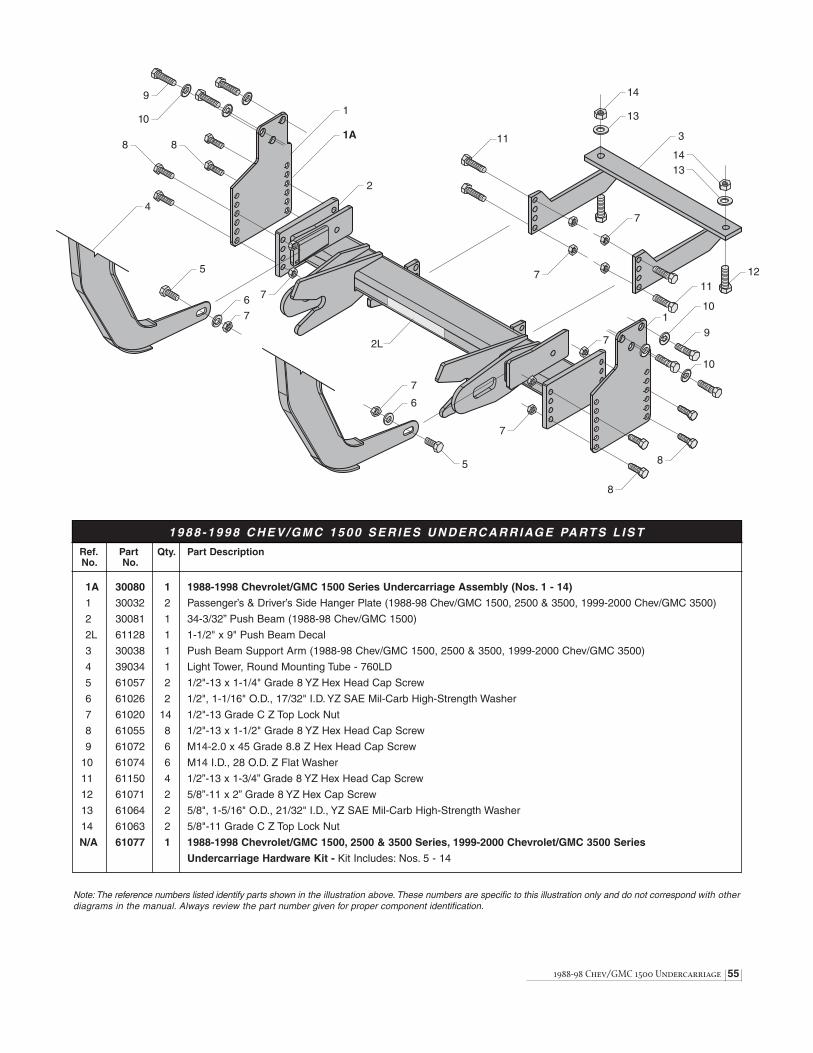
1988-98 Chev/GMC 1500 Undercarriage 55
Ref. Part Qty. Part DescriptionNo. No.
1A 30080 1 1988-1998 Chevrolet/GMC 1500 Series Undercarriage Assembly (Nos. 1 - 14)
1 30032 2 Passenger’s & Driver’s Side Hanger Plate (1988-98 Chev/GMC 1500, 2500 & 3500, 1999-2000 Chev/GMC 3500)
2 30081 1 34-3/32” Push Beam (1988-98 Chev/GMC 1500)
2L 61128 1 1-1/2" x 9" Push Beam Decal
3 30038 1 Push Beam Support Arm (1988-98 Chev/GMC 1500, 2500 & 3500, 1999-2000 Chev/GMC 3500)
4 39034 1 Light Tower, Round Mounting Tube - 760LD
5 61057 2 1/2"-13 x 1-1/4" Grade 8 YZ Hex Head Cap Screw
6 61026 2 1/2", 1-1/16" O.D., 17/32" I.D. YZ SAE Mil-Carb High-Strength Washer
7 61020 14 1/2"-13 Grade C Z Top Lock Nut
8 61055 8 1/2"-13 x 1-1/2" Grade 8 YZ Hex Head Cap Screw
9 61072 6 M14-2.0 x 45 Grade 8.8 Z Hex Head Cap Screw
10 61074 6 M14 I.D., 28 O.D. Z Flat Washer
11 61150 4 1/2”-13 x 1-3/4” Grade 8 YZ Hex Head Cap Screw
12 61071 2 5/8”-11 x 2” Grade 8 YZ Hex Cap Screw
13 61064 2 5/8", 1-5/16" O.D., 21/32" I.D., YZ SAE Mil-Carb High-Strength Washer
14 61063 2 5/8"-11 Grade C Z Top Lock Nut
N/A 61077 1 1988-1998 Chevrolet/GMC 1500, 2500 & 3500 Series, 1999-2000 Chevrolet/GMC 3500 Series
Undercarriage Hardware Kit - Kit Includes: Nos. 5 - 14
Note: The reference numbers listed identify parts shown in the illustration above. These numbers are specific to this illustration only and do not correspond with otherdiagrams in the manual. Always review the part number given for proper component identification.
1988 -1998 CHEV/GMC 1500 SERIES UNDERCARRIAGE PARTS L IST
6
7
5
4
5
6
7
2L
1
2
8 8
10
9
7
7
7
8
1A 3
7
11
11
13
14
127
1314
110
9
10
8

56 1982-87 Chev/GMC C20/C30 & K20/K30 Under.
12-1/2"
WARNING: Most new trucks areequipped with driver and passenger’s
side air bags. DO NOT remove, disable, orreposition any sensory equipment related tothe safe operation of the air bags.
ALWAYS follow the vehicle manufacturer’srecommendations for installing snowplowingequipment.
Failure to comply with the above warning mayresult in serious injury or death.
CAUTION: If your vehicle is equippedwith oversize tires, they may come
into contact with the undercarriage hangerplates when turning the vehicle.
The problem may be resolved by setting thesteering stops on the vehicle. If this does notcorrect the problem, the original tires will needto be installed on the vehicle.
The recommended push beam height for allundercarriage assemblies is 12-1/2" from thecenter of the push beam to level ground. DO NOTexceed 14" in height for any undercarriage.
1982-1987 Chevrolet/GMC C20/C30 & K20/K30Undercarriage
1. Begin the assembly by removing (if applicable) both 1/2"-13 x 2-1/2" boltswith washers and nuts that attach each tow hook to the truck frame rail.Discard all hardware.
2. Next, remove both 7/16"-14 x 1-1/4" bolts and 3/8" lock washers from therear mount of each bumper support bracket. Note: Each hole containsa welded nut on the inside of the truck frame rail eliminating the need for new hardware; however, top lock nuts and washers are provided shouldthe welded nuts be corroded or the threads have been damaged.
3. Position the DRIVER’S SIDE HANGER PLATE on the inside of the truckframe rail and in front of the sway bar crossmember. Note: The bushingsshould rest against the frame and the gussets should face the vehicle’stires. Align the top and bottom rear bushings with the holes for the bumpersupport bracket. Secure the plate with two 7/16"-14 x 4-1/2" bolts. If needed,replace the welded nuts on the frame with the 7/16" washers and top locknuts provided.
4. Align the three front bushings on the hanger plate with the holes for thetow hook mounts located in the truck frame rail. Position one 1/2"-13 x 4-1/2"bolt through each bushing and secure with one 1/2" washer and top lock nut.
5. Repeat steps #3 & #4 to install the PASSENGER’S SIDE HANGER PLATE.
6. Mount the PUSH BEAM to each hanger plate using two 1/2"-13 x 1-1/2"bolts and top lock nuts at the front of the beam. The rear push beammount holes receive 1/2"-13 x 2" bolts. Note: The proper height for thepush beam is approximately 12-1/2" from the ground to the center of thepush beam.
7. Next, align the top hole on the PASSENGER’S SIDE HANGER PLATESUPPORT ARM with the top hole on the inside of the push beam. Fit thesupport arm against the truck frame rail and mark the hole locations onthe frame. Drill two holes into the truck frame to properly mount the supportplate. Attach the support plate to the vehicle using two 1/2"-13 x 1-1/2"bolts with washers and top lock nuts. Complete the same installation for theDRIVER’S SIDE HANGER PLATE SUPPORT ARM. The support armmounts to the outside of the hanger plate. Align the top hole on the supportto the top hole on the hanger plate.
8. Once all of the undercarriage plates have been positioned and the properpush beam height is set, proceed to tighten all top lock nuts. Referencethe chart on page 4 for maximum bolt torque.
9. Position the LIGHT TOWER into the accepting pockets on the push beamand tighten using two 1/2"-13 x 1-1/4" Grade 8 YZ hex cap screws withwashers. Secure each bolt with a 1/2" top locking nut. Mount each PLOWHEADLIGHT to the light tower with the hardware kit provided.
Complete the assembly by plugging the connectors from the lights into the connectors on the vehicle wire harness.

Ref. Part Qty. Part DescriptionNo. No.
1A 30055 1 1982-1987 Chevrolet/GMC C20/C30 & K20/K30 Undercarriage Assembly (Nos. 1 - 15)
1 30048 1 Passenger’s Side Hanger Plate (1982-87 Chevrolet/GMC C20/C30 & K20/K30)
2 30053 1 26-1/4" Push Beam (1982-87 Chev/GMC C20/C30 & K20/K30 & 1979-93 Dodge 2500 & 3500)
2L 61085 1 2-1/8" x 13-1/8" Push Beam Decal
3 30046 1 Driver’s Side Hanger Plate (1982-87 Chevrolet/GMC C20/C30 & K20/K30)
4 30124 1 Passenger’s Side Hanger Plate Support Arm
5 30120 1 Driver’s Side Hanger Plate Support Arm
6 39032 1 Light Tower, Round Mounting Tube
7 61152 6 1/2"-13 x 4-1/2" Grade 8 YZ Hex Head Cap Screw
8 61026 12 1/2", 1-1/16" O.D., 17/32" I.D. YZ SAE Mil-Carb High-Strength Washer
9 61020 22 1/2"-13 Grade C Z Top Lock Nut
10 61055 8 1/2"-13 x 1-1/2" Grade 8 YZ Hex Head Cap Screw
11 61153 4 7/16"-14 x 4-1/2" Grade 8 YZ Hex Head Cap Screw
12 61162 4 7/16", 59/64" O.D., 15/32" I.D. YZ SAE Mil-Carb High-Strength Washer
13 61154 4 7/16"-14 Grade C Z Top Lock Nut
14 61018 6 1/2"-13 x 2" Grade 8 YZ Hex Head Cap Screw
15 61057 2 1/2"-13 x 1-1/4" Grade 8 YZ Hex Head Cap Screw
N/A 61156 1 1982-1987 Chevrolet/GMC C20/C30 & K20/K30 Undercarriage Hardware Kit - Kit Includes: Nos. 7 - 15
1982-87 Chev/GMC C20/C30 & K20/K30 Under. 57
Note: The reference numbers listed identify parts shown in the illustration above. These numbers are specific to this illustration only and do not correspond with otherdiagrams issued. Always review the part number given for proper component identification.
1 9 8 2 - 1 9 8 7 C H E V R O L E T / G M C C 2 0 / C 3 0 & K 2 0 / K 3 0 U N D E R C A R R I AG E PA R T S L I S T
1A1
2 3
8
9
6
15
8
9
4
52L
7
7
8
8
8
9
9
9
9
98
10
1011
11
12
13
1213
15
14
14
10
10
14
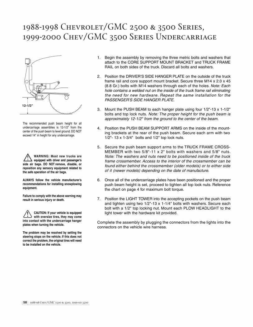
58 1988-98 Chev/GMC 2500 & 3500, 1999-00 3500
1988-1998 Chevrolet/GMC 2500 & 3500 Series, 1999-2000 Chev/GMC 3500 Series Undercarriage
12-1/2"
WARNING: Most new trucks areequipped with driver and passenger’s
side air bags. DO NOT remove, disable, orreposition any sensory equipment related tothe safe operation of the air bags.
ALWAYS follow the vehicle manufacturer’srecommendations for installing snowplowingequipment.
Failure to comply with the above warning mayresult in serious injury or death.
CAUTION: If your vehicle is equippedwith oversize tires, they may come
into contact with the undercarriage hangerplates when turning the vehicle.
The problem may be resolved by setting thesteering stops on the vehicle. If this does notcorrect the problem, the original tires will needto be installed on the vehicle.
The recommended push beam height for allundercarriage assemblies is 12-1/2" from thecenter of the push beam to level ground. DO NOTexceed 14" in height for any undercarriage.
1. Begin the assembly by removing the three metric bolts and washers thatattach to the CORE SUPPORT MOUNT BRACKET and TRUCK FRAMERAIL on both sides of the truck. Discard all bolts and washers.
2. Position the DRIVER’S SIDE HANGER PLATE on the outside of the truckframe rail and core support mount bracket. Secure three M14 x 2.0 x 45(8.8 Gr.) bolts with M14 washers through each of the holes. Note: Eachhole contains a welded nut on the inside of the truck frame rail eliminatingthe need for new hardware. Repeat the same installation for the PASSENGER’S SIDE HANGER PLATE.
3. Mount the PUSH BEAM to each hanger plate using four 1/2"-13 x 1-1/2"bolts and top lock nuts. Note: The proper height for the push beam isapproximately 12-1/2" from the ground to the center of the beam.
4. Position the PUSH BEAM SUPPORT ARMS on the inside of the mount-ing brackets at the rear of the push beam. Secure each arm with two1/2"- 13 x 1-3/4" bolts and 1/2" top lock nuts.
5. Secure the push beam support arms to the TRUCK FRAME CROSS-MEMBER with two 5/8"-11 x 2" bolts with washers and 5/8" nuts.Note: The washers and nuts need to be positioned inside of the truckframe crossmember. Access to the interior of the crossmember can befound either behind the crossmember (older models) or to either sideof it (newer models) depending on the date of manufacture.
6. Once all of the undercarriage plates have been positioned and the properpush beam height is set, proceed to tighten all top lock nuts. Referencethe chart on page 4 for maximum bolt torque.
7. Position the LIGHT TOWER into the accepting pockets on the push beamand tighten using two 1/2"-13 x 1-1/4" bolts with washers. Secure eachbolt with a 1/2" top locking nut. Mount each PLOW HEADLIGHT to thelight tower with the hardware kit provided.
Complete the assembly by plugging the connectors from the lights into the connectors on the vehicle wire harness.
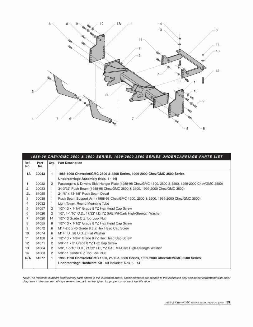
1988-98 Chev/GMC 2500 & 3500, 1999-00 3500 59
Ref. Part Qty. Part DescriptionNo. No.
1A 30043 1 1988-1998 Chevrolet/GMC 2500 & 3500 Series, 1999-2000 Chev/GMC 3500 Series
Undercarriage Assembly (Nos. 1 - 14)
1 30032 2 Passenger’s & Driver’s Side Hanger Plate (1988-98 Chev/GMC 1500, 2500 & 3500, 1999-2000 Chev/GMC 3500)
2 30033 1 34-3/32” Push Beam (1988-98 Chev/GMC 2500 & 3500, 1999-2000 Chev/GMC 3500)
2L 61085 1 2-1/8" x 13-1/8" Push Beam Decal
3 30038 1 Push Beam Support Arm (1988-98 Chev/GMC 1500, 2500 & 3500, 1999-2000 Chev/GMC 3500)
4 39032 1 Light Tower, Round Mounting Tube
5 61057 2 1/2"-13 x 1-1/4" Grade 8 YZ Hex Head Cap Screw
6 61026 2 1/2", 1-1/16" O.D., 17/32" I.D. YZ SAE Mil-Carb High-Strength Washer
7 61020 14 1/2"-13 Grade C Z Top Lock Nut
8 61055 8 1/2"-13 x 1-1/2" Grade 8 YZ Hex Head Cap Screw
9 61072 6 M14-2.0 x 45 Grade 8.8 Z Hex Head Cap Screw
10 61074 6 M14 I.D., 28 O.D. Z Flat Washer
11 61150 4 1/2”-13 x 1-3/4” Grade 8 YZ Hex Head Cap Screw
12 61071 2 5/8”-11 x 2” Grade 8 YZ Hex Cap Screw
13 61064 2 5/8", 1-5/16" O.D., 21/32" I.D., YZ SAE Mil-Carb High-Strength Washer
14 61063 2 5/8"-11 Grade C Z Top Lock Nut
N/A 61077 1 1988-1998 Chevrolet/GMC 1500, 2500 & 3500 Series, 1999-2000 Chevrolet/GMC 3500 Series
Undercarriage Hardware Kit - Kit Includes: Nos. 5 - 14
Note: The reference numbers listed identify parts shown in the illustration above. These numbers are specific to this illustration only and do not correspond with otherdiagrams in the manual. Always review the part number given for proper component identification.
1988 -98 CHEV/GMC 2500 & 3500 SERIES , 1999 -2000 3500 SERIES UNDERCARRIAGE PARTS L IST
1
2
3
1
4
5
6
8
8
7
7
8 9
9
10
10
11
11
712
13
14
14
13
1A
2L
8
7

60 1988-00 Chev/GMC 1 ton hd 2wd Under.
1988-2000 Chev/GMC 1 ton heavy-duty 2wd Undercarriage
12-1/2"
WARNING: Most new trucks areequipped with driver and passenger’s
side air bags. DO NOT remove, disable, orreposition any sensory equipment related tothe safe operation of the air bags.
ALWAYS follow the vehicle manufacturer’srecommendations for installing snowplowingequipment.
Failure to comply with the above warning mayresult in serious injury or death.
CAUTION: If your vehicle is equippedwith oversize tires, they may come
into contact with the undercarriage hangerplates when turning the vehicle.
The problem may be resolved by setting thesteering stops on the vehicle. If this does notcorrect the problem, the original tires will needto be installed on the vehicle.
The recommended push beam height for allundercarriage assemblies is 12-1/2" from thecenter of the push beam to level ground. DO NOTexceed 14" in height for any undercarriage.
1. Begin the assembly by removing both M12-1.75 x 35 (8.8 Gr.) bolts withwashers and flanged nuts from the rear mount of each bumper supportbracket. Discard all hardware.
2. Next, position the DRIVER’S SIDE HANGER PLATE on the outside of thetruck frame rail and into the core support mount on the frame. Note: Thecut-out in the hanger plate fits over the leaf spring clamp bolt. Align theholes from the bumper support bracket mount to those on the hanger plateand secure using two 1/2"-13 x 1-1/2" bolts and 1/2" top lock nuts. Securetwo additional 1/2"-13 x 1-1/2" bolts and nuts opposite the bumper supportmount hardware.
3. Complete the hanger plate installation by installing two 1/2"-13 x 1-1/2"bolts with welded tabs through the middle mount holes. Attach a thin gaugewire to each screw and feed the wire through the opening in the frame atthe spring shackle bolt. Pull the wire and hex cap screw through the bottommount hole in the frame and hanger plate. Secure the cap screw with a1/2" top lock nut. Repeat the same procedure for the top mount hole.
4. Repeat steps #2 & #3 to install the PASSENGER’S SIDE HANGER PLATE.
5. Mount the PUSH BEAM to the front hanger plate mount holes using four1/2"-13 x 1-1/2" bolts and top lock nuts. Note: The proper height for thepush beam is approximately 12-1/2" from the ground to the center of thepush beam.
6. Align the hole in the DRIVER’S SIDE PUSH BEAM SUPPORT ARM tothe mount hole on the frame in front of the vehicle shock mount. Securethe support arm by “snaking” a 1/2"-13 x 1-1/2" bolt with welded tab throughthe opening in the frame at the spring shackle bolt. Pull the wire and boltthrough the mount hole in the frame and support arm. Secure the bolt witha 1/2" top lock nut. Next, align the holes in the support arm to the rear mountholes on the hanger plate and push beam. Secure the plates using two1/2"-13 x 2-1/4" bolts and 1/2" top lock nuts. Position a third bolt (1/2"-13x 1-1/2") through the bottom mount hole in the hanger plate and push beamand secure with one 1/2" top lock nut.
7. Repeat step #6 to install the PASSENGER’S SIDE PUSH BEAMSUPPORT ARM.
8. Once all of the undercarriage plates have been positioned and the properpush beam height is set, proceed to tighten all top lock nuts. Referencethe chart on page 4 for maximum bolt torque.
9. Position the LIGHT TOWER into the accepting pockets on the push beamand tighten using two 1/2"-13 x 1-1/4" Grade 8 YZ hex cap screws withwashers. Secure each bolt with a 1/2" top locking nut. Mount each PLOWHEADLIGHT to the light tower with the hardware kit provided.
Complete the assembly by plugging the connectors from the lights into the connectors on the vehicle wire harness.

1988-00 Chev/GMC 1 ton hd 2wd Under. 61
Ref. Part Qty. Part DescriptionNo. No.
1A 30071 1 1988 -2000 Chevrolet/GMC 1 Ton Heavy-Duty 2WD Undercarriage Assembly (Nos. 1 - 12)
1 30063 1 Passenger’s Side Push Beam Support Arm (1988-2000 Chev/GMC 1 Ton HD 2WD)
2 30064 1 Passenger’s Side Hanger Plate (1988-2000 Chev/GMC 1 Ton HD 2WD)
3 30070 1 37" Push Beam (1988-2000 Chev/GMC 1 Ton HD 2WD)
3L 61085 1 2-1/8" x 13-1/8" Push Beam Decal
4 30065 1 Driver’s Side Hanger Plate (1988-2000 Chev/GMC 1 Ton HD 2WD)
5 30067 1 Driver’s Side Push Beam Support Arm (1988-2000 Chev/GMC 1 Ton HD 2WD)
6 39032 1 Light Tower, Round Mounting Tube
7 61055 14 1/2"-13 x 1-1/2" Grade 8 YZ Hex Head Cap Screw
8 61020 26 1/2"-13 Grade C Z Top Lock Nut
9 61151 6 1/2"-13 x 1-1/2" Grade 8 YZ Hex Head Cap Screw with Welded Tab
10 61054 4 1/2"-13 x 2-1/4" Grade 8 YZ Hex Head Cap Screw
11 61026 8 1/2", 1-1/16" O.D., 17/32" I.D. YZ SAE Mil-Carb High-Strength Washer
12 61057 2 1/2"-13 x 1-1/4" Grade 8 YZ Hex Head Cap Screw
N/A 61160 1 1988 -2000 Chevrolet/GMC 1 Ton Heavy-Duty 2WD Undercarriage Hardware Kit - Kit Includes: Nos. 7 - 12
Note: The reference numbers listed identify parts shown in the illustration above. These numbers are specific to this illustration only and do not correspond with otherdiagrams issued. Always review the part number given for proper component identification.
1 9 8 8 - 2 0 0 0 C H E V R O L E T / G M C 1 TO N H D 2 W D U N D E R C A R R I AG E PA R T S L I S T
1
1A
2
3
4
3L 5
6
8
7
98
9
8
9
8
7
9
8
10
78
10
11
12
8
7
7
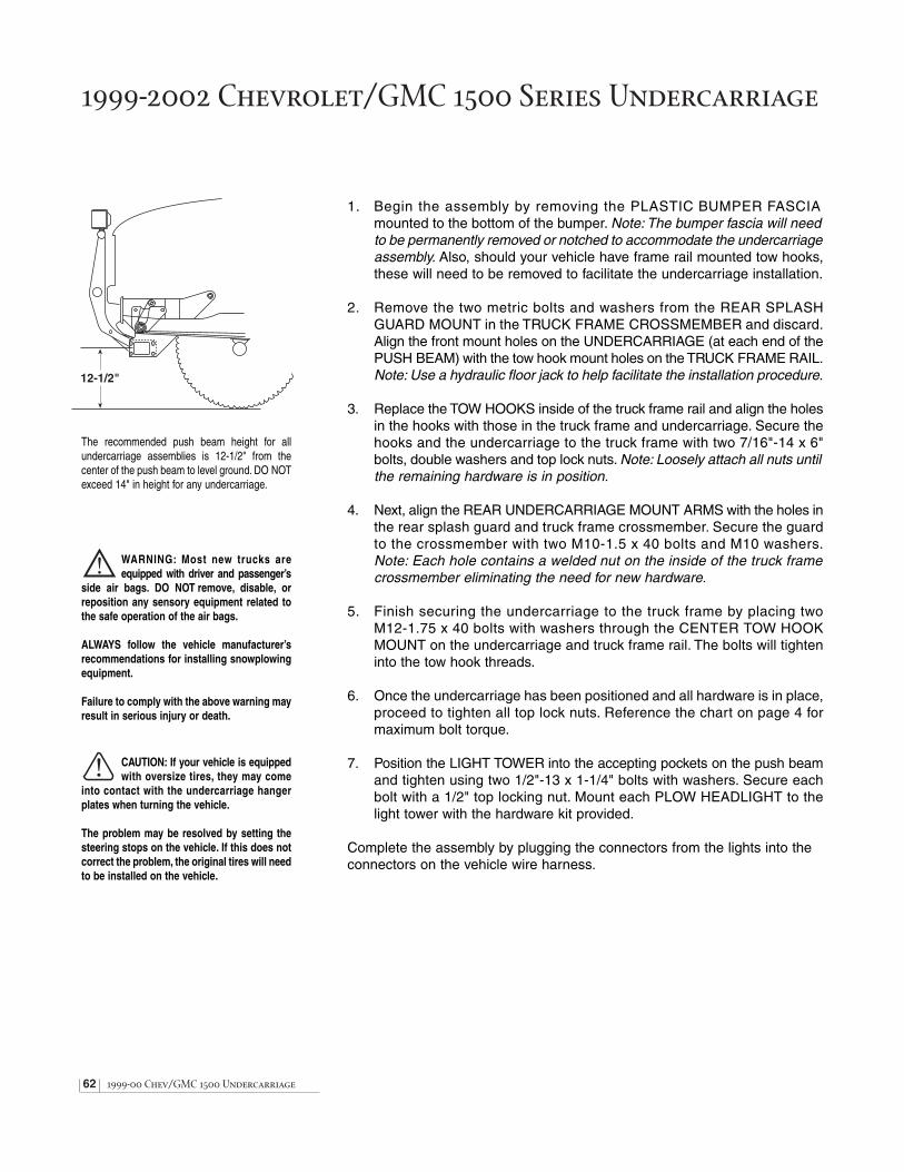
62 1999-00 Chev/GMC 1500 Undercarriage
1999-2002 Chevrolet/GMC 1500 Series Undercarriage
12-1/2"
WARNING: Most new trucks areequipped with driver and passenger’s
side air bags. DO NOT remove, disable, orreposition any sensory equipment related tothe safe operation of the air bags.
ALWAYS follow the vehicle manufacturer’srecommendations for installing snowplowingequipment.
Failure to comply with the above warning mayresult in serious injury or death.
CAUTION: If your vehicle is equippedwith oversize tires, they may come
into contact with the undercarriage hangerplates when turning the vehicle.
The problem may be resolved by setting thesteering stops on the vehicle. If this does notcorrect the problem, the original tires will needto be installed on the vehicle.
The recommended push beam height for allundercarriage assemblies is 12-1/2" from thecenter of the push beam to level ground. DO NOTexceed 14" in height for any undercarriage.
1. Begin the assembly by removing the PLASTIC BUMPER FASCIA mounted to the bottom of the bumper. Note: The bumper fascia will needto be permanently removed or notched to accommodate the undercarriageassembly. Also, should your vehicle have frame rail mounted tow hooks,these will need to be removed to facilitate the undercarriage installation.
2. Remove the two metric bolts and washers from the REAR SPLASHGUARD MOUNT in the TRUCK FRAME CROSSMEMBER and discard.Align the front mount holes on the UNDERCARRIAGE (at each end of thePUSH BEAM) with the tow hook mount holes on the TRUCK FRAME RAIL.Note: Use a hydraulic floor jack to help facilitate the installation procedure.
3. Replace the TOW HOOKS inside of the truck frame rail and align the holesin the hooks with those in the truck frame and undercarriage. Secure thehooks and the undercarriage to the truck frame with two 7/16"-14 x 6"bolts, double washers and top lock nuts. Note: Loosely attach all nuts untilthe remaining hardware is in position.
4. Next, align the REAR UNDERCARRIAGE MOUNT ARMS with the holes inthe rear splash guard and truck frame crossmember. Secure the guardto the crossmember with two M10-1.5 x 40 bolts and M10 washers.Note: Each hole contains a welded nut on the inside of the truck framecrossmember eliminating the need for new hardware.
5. Finish securing the undercarriage to the truck frame by placing two M12-1.75 x 40 bolts with washers through the CENTER TOW HOOKMOUNT on the undercarriage and truck frame rail. The bolts will tighteninto the tow hook threads.
6. Once the undercarriage has been positioned and all hardware is in place,proceed to tighten all top lock nuts. Reference the chart on page 4 formaximum bolt torque.
7. Position the LIGHT TOWER into the accepting pockets on the push beamand tighten using two 1/2"-13 x 1-1/4" bolts with washers. Secure eachbolt with a 1/2" top locking nut. Mount each PLOW HEADLIGHT to thelight tower with the hardware kit provided.
Complete the assembly by plugging the connectors from the lights into the connectors on the vehicle wire harness.

1999-00 Chev/GMC 1500 Undercarriage 63
Note: The reference numbers listed identify parts shown in the illustration above. These numbers are specific to this illustration only and do not correspond with otherdiagrams in the manual. Always review the part number given for proper component identification.
1 9 9 9 - 2 0 0 2 C H E V R O L E T / G M C 1 5 0 0 S E R I E S U N D E R C A R R I AG E PA R T S L I S T
2
3
4
5
4
5
3
1L
1A1
6 7
87
9
978
12
11
12
11
10
10
Ref. Part Qty. Part DescriptionNo. No.
1A 30087 1 1999-2002 Chevrolet / GMC 1500 Series Undercarriage Assembly (Nos. 1 - 12)
1 30072 1 35-3/4" Push Beam (1999-2002 Chev/GMC 1500 Series)
1L 61128 1 1-1/2" x 9" Push Beam Decal
2 39034 1 Light Tower, Round Mounting Tube - Model 760LD
3 61057 2 1/2"-13 x 1-1/4" Grade 8 YZ Hex Head Cap Screw
4 61026 2 1/2", 1-1/16" O.D., 17/32" I.D. YZ SAE Mil-Carb High-Strength Washer
5 61020 2 1/2"-13 Grade C Z Top Lock Nut
6 61249 2 7/16"-14 x 6" Grade 8 YZ Hex Head Cap Screw
7 61162 4 7/16", 59/64" O.D., 15/32" I.D. YZ SAE Mil-Carb High-Strength Washer
8 61154 2 7/16"-14 Grade C Top Lock Nut
9 61069 2 M12-1.75 x 40 Grade 8.8 Z Hex Head Cap Screw
10 61070 2 M12 I.D., 24 O.D. Z Flat Washer
11 61250 2 M10-1.5 x 40 Grade 8.8 Z Hex Head Cap Screw
12 61251 2 M10 I.D., 21 O.D. Z Flat Washer
N/A 61194 1 99-02 Chevrolet / GMC 1500 & 1500 Z-71 Off-Road Series Undercarriage Hardware Kit - Kit Includes: Nos. 3 - 12
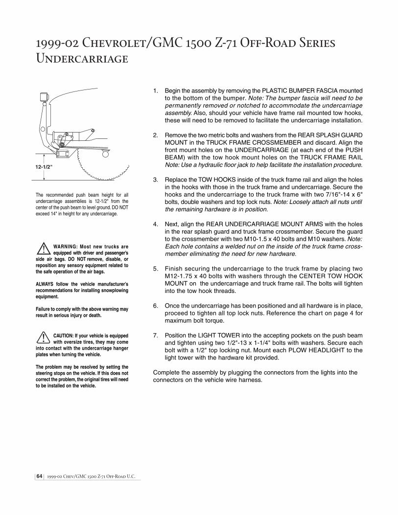
64 1999-02 Chev/GMC 1500 Z-71 Off-Road U.C.
1999-02 Chevrolet/GMC 1500 Z-71 Off-Road SeriesUndercarriage
12-1/2"
WARNING: Most new trucks areequipped with driver and passenger’s
side air bags. DO NOT remove, disable, orreposition any sensory equipment related tothe safe operation of the air bags.
ALWAYS follow the vehicle manufacturer’srecommendations for installing snowplowingequipment.
Failure to comply with the above warning mayresult in serious injury or death.
CAUTION: If your vehicle is equippedwith oversize tires, they may come
into contact with the undercarriage hangerplates when turning the vehicle.
The problem may be resolved by setting thesteering stops on the vehicle. If this does notcorrect the problem, the original tires will needto be installed on the vehicle.
The recommended push beam height for allundercarriage assemblies is 12-1/2" from thecenter of the push beam to level ground. DO NOTexceed 14" in height for any undercarriage.
1. Begin the assembly by removing the PLASTIC BUMPER FASCIA mountedto the bottom of the bumper. Note: The bumper fascia will need to be permanently removed or notched to accommodate the undercarriageassembly. Also, should your vehicle have frame rail mounted tow hooks,these will need to be removed to facilitate the undercarriage installation.
2. Remove the two metric bolts and washers from the REAR SPLASH GUARDMOUNT in the TRUCK FRAME CROSSMEMBER and discard. Align thefront mount holes on the UNDERCARRIAGE (at each end of the PUSHBEAM) with the tow hook mount holes on the TRUCK FRAME RAILNote: Use a hydraulic floor jack to help facilitate the installation procedure.
3. Replace the TOW HOOKS inside of the truck frame rail and align the holesin the hooks with those in the truck frame and undercarriage. Secure thehooks and the undercarriage to the truck frame with two 7/16"-14 x 6"bolts, double washers and top lock nuts. Note: Loosely attach all nuts untilthe remaining hardware is in position.
4. Next, align the REAR UNDERCARRIAGE MOUNT ARMS with the holesin the rear splash guard and truck frame crossmember. Secure the guardto the crossmember with two M10-1.5 x 40 bolts and M10 washers. Note:Each hole contains a welded nut on the inside of the truck frame cross-member eliminating the need for new hardware.
5. Finish securing the undercarriage to the truck frame by placing two M12-1.75 x 40 bolts with washers through the CENTER TOW HOOKMOUNT on the undercarriage and truck frame rail. The bolts will tighteninto the tow hook threads.
6. Once the undercarriage has been positioned and all hardware is in place,proceed to tighten all top lock nuts. Reference the chart on page 4 formaximum bolt torque.
7. Position the LIGHT TOWER into the accepting pockets on the push beamand tighten using two 1/2"-13 x 1-1/4" bolts with washers. Secure eachbolt with a 1/2" top locking nut. Mount each PLOW HEADLIGHT to thelight tower with the hardware kit provided.
Complete the assembly by plugging the connectors from the lights into the connectors on the vehicle wire harness.

1999-02 Chev/GMC 1500 Z-71 Off-Road U.C. 65
Ref. Part Qty. Part DescriptionNo. No.
1A 30088 1 1999-2002 Chevrolet / GMC 1500 Z-71 Off-Road Series Undercarriage Assembly (Nos. 1 - 12)
1 30084 1 35-3/4" Push Beam (1999-2002 Chev/GMC 1500 Z-71 Off-Road Series)
1L 61128 1 1-1/2" x 9" Push Beam Decal
2 39034 1 Light Tower, Round Mounting Tube - Model 760LD
3 61057 2 1/2"-13 x 1-1/4" Grade 8 YZ Hex Head Cap Screw
4 61026 2 1/2", 1-1/16" O.D., 17/32" I.D. YZ SAE Mil-Carb High-Strength Washer
5 61020 2 1/2"-13 Grade C Z Top Lock Nut
6 61249 2 7/16"-14 x 6" Grade 8 YZ Hex Head Cap Screw
7 61162 4 7/16", 59/64" O.D., 15/32" I.D. YZ SAE Mil-Carb High-Strength Washer
8 61154 2 7/16"-14 Grade C Top Lock Nut
9 61069 2 M12-1.75 x 40 Grade 8.8 Z Hex Head Cap Screw
10 61070 2 M12 I.D., 24 O.D. Z Flat Washer
11 61250 2 M10-1.5 x 40 Grade 8.8 Z Hex Head Cap Screw
12 61251 2 M10 I.D., 21 O.D. Z Flat Washer
N/A 61194 1 1999-02 Chevrolet / GMC 1500 & 1500 Z-71 Off-Road Series Undercarriage Hardware Kit - Kit Includes: Nos. 3-12
4
5
3
2
3
4
5
1A1
6 7
9
10
9
10
12
11
6
12
11
78
87
1L
7
Note: The reference numbers listed identify parts shown in the illustration above. These numbers are specific to this illustration only and do not correspond with otherdiagrams in the manual. Always review the part number given for proper component identification.
1 9 9 9 - 2 0 0 2 C H E V R O L E T / G M C 1 5 0 0 Z - 7 1 O F F - R OA D S E R I E S U N D E R C A R R I AG E PA R T S L I S T
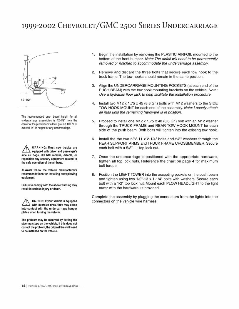
66 1999-02 Chev/GMC 2500 Undercarriage
1999-2002 Chevrolet/GMC 2500 Series Undercarriage
1. Begin the installation by removing the PLASTIC AIRFOIL mounted to the bottom of the front bumper. Note: The airfoil will need to be permanentlyremoved or notched to accommodate the undercarriage assembly.
2. Remove and discard the three bolts that secure each tow hook to thetruck frame. The tow hooks should remain in the same position.
3. Align the UNDERCARRIAGE MOUNTING POCKETS (at each end of thePUSH BEAM) with the tow hook mounting brackets on the vehicle. Note:Use a hydraulic floor jack to help facilitate the installation procedure.
4. Install two M12 x 1.75 x 45 (8.8 Gr.) bolts with M12 washers to the SIDETOW HOOK MOUNT for each end of the assembly. Note: Loosely attachall nuts until the remaining hardware is in position.
5. Proceed to install one M12 x 1.75 x 40 (8.8 Gr.) bolt with an M12 washerthrough the TRUCK FRAME and REAR TOW HOOK MOUNT for eachside of the push beam. Both bolts will tighten into the existing tow hook.
6. Install the the two 5/8"-11 x 2-1/4" bolts and 5/8" washers through theREAR SUPPORT ARMS and TRUCK FRAME CROSSMEMBER. Secureeach bolt with a 5/8"-11 top lock nut.
7. Once the undercarriage is positioned with the appropriate hardware,tighten all top lock nuts. Reference the chart on page 4 for maximumbolt torque.
8. Position the LIGHT TOWER into the accepting pockets on the push beamand tighten using two 1/2"-13 x 1-1/4" bolts with washers. Secure eachbolt with a 1/2" top lock nut. Mount each PLOW HEADLIGHT to the lighttower with the hardware kit provided.
Complete the assembly by plugging the connectors from the lights into the connectors on the vehicle wire harness.
12-1/2"
WARNING: Most new trucks areequipped with driver and passenger’s
side air bags. DO NOT remove, disable, orreposition any sensory equipment related tothe safe operation of the air bags.
ALWAYS follow the vehicle manufacturer’srecommendations for installing snowplowingequipment.
Failure to comply with the above warning mayresult in serious injury or death.
CAUTION: If your vehicle is equippedwith oversize tires, they may come
into contact with the undercarriage hangerplates when turning the vehicle.
The problem may be resolved by setting thesteering stops on the vehicle. If this does notcorrect the problem, the original tires will needto be installed on the vehicle.
The recommended push beam height for allundercarriage assemblies is 12-1/2" from thecenter of the push beam to level ground. DO NOTexceed 14" in height for any undercarriage.

1999-02 Chev/GMC 2500 Undercarriage 67
Ref. Part Qty. Part DescriptionNo. No.
1A 30042 1 1999-2002 Chevrolet / GMC 2500 Series Undercarriage Assembly (Nos. 1 - 11)
1 30037 1 37" Push Beam (1999-2002 Chev/GMC 2500 Series)
1L 61128 1 1-1/2" x 9" Push Beam Decal
2 39032 1 Light Tower, Round Mounting Tube
3 61057 2 1/2"-13 x 1-1/4" Grade 8 YZ Hex Head Cap Screw
4 61026 2 1/2", 1-1/16" O.D., 17/32" I.D. YZ SAE Mil-Carb High-Strength Washer
5 61020 2 1/2"-13 Grade C Z Top Lock Nut
6 61068 4 M12-1.75 x 45 Grade 8.8 Z Hex Head Cap Screw
7 61070 6 M12 I.D., 24 O.D. Z Flat Washer
8 61069 2 M12-1.75 x 40 Grade 8.8 Z Hex Head Cap Screw
9 61067 2 5/8"-11 x 2-1/4" Grade 8 YZ Hex Cap Screw
10 61064 2 5/8", 1-5/16" O.D., 21/32" I.D., YZ SAE Mil-Carb High-Strength Washer
11 61063 2 5/8"-11 Grade C Z Top Lock Nut
N/A 61076 1 1999-2002 Chevrolet / GMC 2500 Series Undercarriage Hardware Kit - Kit Includes: Nos. 3 - 11
1
1A
2
3
5
6
7
6
7
7
7
8
8
9
9
10
10
11
11
1L
4
Note: The reference numbers listed identify parts shown in the illustration above. These numbers are specific to this illustration only and do not correspond with otherdiagrams in the manual. Always review the part number given for proper component identification.
1 9 9 9 - 2 0 0 2 C H E V R O L E T / G M C 2 5 0 0 S E R I E S U N D E R C A R R I AG E PA R T S L I S T

68 1979-93 Dodge 2500 & 3500 Undercarriage
12-1/2"
WARNING: Most new trucks areequipped with driver and passenger’s
side air bags. DO NOT remove, disable, orreposition any sensory equipment related tothe safe operation of the air bags.
ALWAYS follow the vehicle manufacturer’srecommendations for installing snowplowingequipment.
Failure to comply with the above warning mayresult in serious injury or death.
CAUTION: If your vehicle is equippedwith oversize tires, they may come
into contact with the undercarriage hangerplates when turning the vehicle.
The problem may be resolved by setting thesteering stops on the vehicle. If this does notcorrect the problem, the original tires will needto be installed on the vehicle.
The recommended push beam height for allundercarriage assemblies is 12-1/2" from thecenter of the push beam to level ground. DO NOTexceed 14" in height for any undercarriage.
1979-1993 Dodge 2500 & 3500 Series Undercarriage
1. Begin the assembly by mounting the HANGER PLATE WELDMENT tothe front crossmember. Note: Depending on the model of your vehicle,the hole locations in the crossmember may be different. Review the diagram to the right for proper bushing and/or spacer mount positions.Once you have determined the mount locations for the hanger plate,insert the STEPPED BUSHINGS and SPACERS (if needed) into position.Secure the hanger plate to the crossmember using four 5/8"-11 x 2"Grade 8 YZ hex cap screws with washers and top lock nuts.
2. Mount the PUSH BEAM to the front hanger plate mount holes using four1/2"-13 x 1-1/2" bolts and top lock nuts. Note: The proper height for thepush beam is approximately 12-1/2" from the ground to the center of thepush beam.
3. Align the hole in the DRIVER’S SIDE PUSH BEAM SUPPORT ARM tothe mount hole on the frame located behind the steering box. Note: Thesupport arm mounts on the inside of the truck frame rail and leaf spring.Secure the arm to the frame with one 5/8"-11 x 4" bolt, washer and toplock nut. Complete the support arm installation by aligning the holes inthe arm to the rear mount holes on the inside of the hanger plate andpush beam. Secure the arm with two 1/2"-13 x 1-3/4" bolts and top lock nuts.
4. Next, position the PASSENGER’S SIDE PUSH BEAM SUPPORT ARMon the outside of the truck frame rail and inside of the leaf spring. Alignthe hole in the support arm with the mount hole on the frame locatedapproximately 14" back from the core support mount. Secure the arm tothe frame with one 5/8"-11 x 1-3/4" bolt, washer and top lock nut. Completethe mount by fastening the arm to the rear mount holes on the inside ofthe hanger plate with two 1/2"-13 x 1-3/4" bolts and top lock nuts.
5. Once all of the undercarriage plates have been positioned and the properpush beam height is set, proceed to tighten all top lock nuts. Referencethe chart on page 4 for maximum bolt torque.
6. Position the LIGHT TOWER into the accepting pockets on the push beamand tighten using two 1/2"-13 x 1-1/4" Grade 8 YZ hex cap screws withwashers. Secure each bolt with a 1/2" top lock nut. Mount each PLOWHEADLIGHT to the light tower with hardware kit provided.
Complete the assembly by plugging the connectors from the lights into the connectors on the vehicle wire harness.
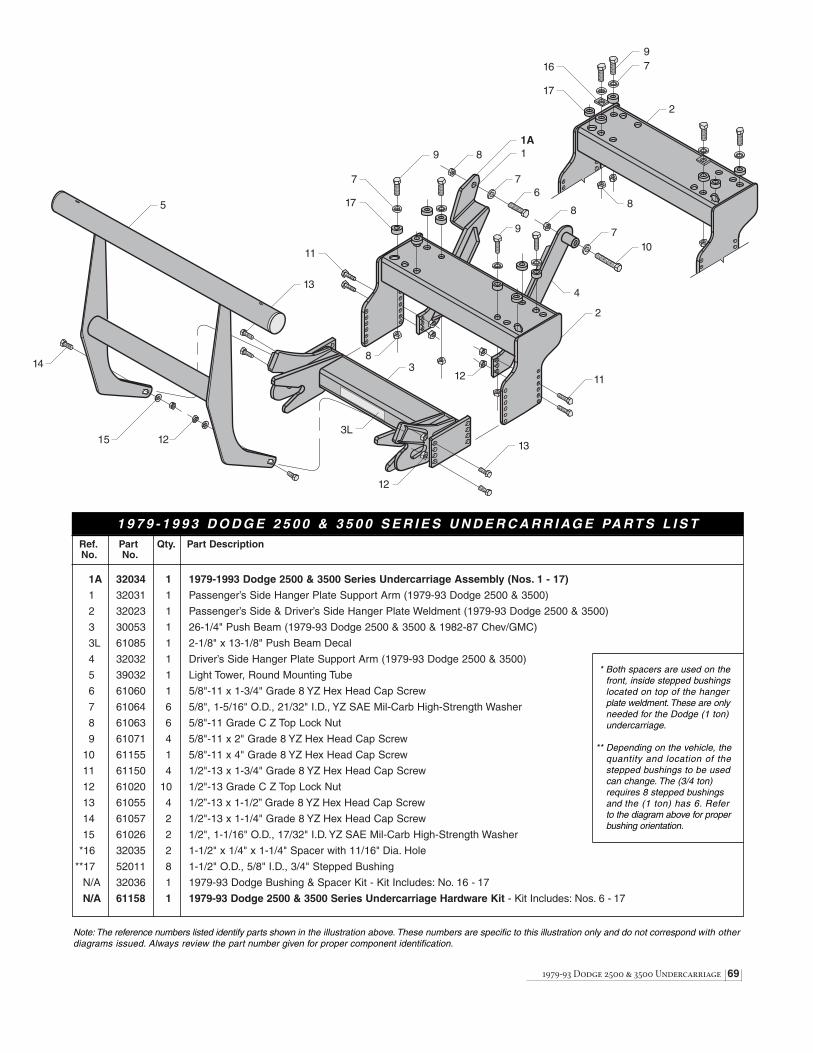
1979-93 Dodge 2500 & 3500 Undercarriage 69
Ref. Part Qty. Part DescriptionNo. No.
1A 32034 1 1979-1993 Dodge 2500 & 3500 Series Undercarriage Assembly (Nos. 1 - 17)
1 32031 1 Passenger’s Side Hanger Plate Support Arm (1979-93 Dodge 2500 & 3500)
2 32023 1 Passenger’s Side & Driver’s Side Hanger Plate Weldment (1979-93 Dodge 2500 & 3500)
3 30053 1 26-1/4" Push Beam (1979-93 Dodge 2500 & 3500 & 1982-87 Chev/GMC)
3L 61085 1 2-1/8" x 13-1/8" Push Beam Decal
4 32032 1 Driver’s Side Hanger Plate Support Arm (1979-93 Dodge 2500 & 3500)
5 39032 1 Light Tower, Round Mounting Tube
6 61060 1 5/8"-11 x 1-3/4" Grade 8 YZ Hex Head Cap Screw
7 61064 6 5/8", 1-5/16" O.D., 21/32" I.D., YZ SAE Mil-Carb High-Strength Washer
8 61063 6 5/8"-11 Grade C Z Top Lock Nut
9 61071 4 5/8"-11 x 2" Grade 8 YZ Hex Head Cap Screw
10 61155 1 5/8"-11 x 4" Grade 8 YZ Hex Head Cap Screw
11 61150 4 1/2"-13 x 1-3/4" Grade 8 YZ Hex Head Cap Screw
12 61020 10 1/2"-13 Grade C Z Top Lock Nut
13 61055 4 1/2”-13 x 1-1/2” Grade 8 YZ Hex Head Cap Screw
14 61057 2 1/2"-13 x 1-1/4" Grade 8 YZ Hex Head Cap Screw
15 61026 2 1/2", 1-1/16" O.D., 17/32" I.D. YZ SAE Mil-Carb High-Strength Washer
*16 32035 2 1-1/2" x 1/4" x 1-1/4" Spacer with 11/16" Dia. Hole
**17 52011 8 1-1/2" O.D., 5/8" I.D., 3/4" Stepped Bushing
N/A 32036 1 1979-93 Dodge Bushing & Spacer Kit - Kit Includes: No. 16 - 17
N/A 61158 1 1979-93 Dodge 2500 & 3500 Series Undercarriage Hardware Kit - Kit Includes: Nos. 6 - 17
13
1A
3
1
6
14
12
2
3L
4
5
7
8
8
8
9
9
7
710
1112
17
11
1697
8
17
2
13
12
15
Note: The reference numbers listed identify parts shown in the illustration above. These numbers are specific to this illustration only and do not correspond with otherdiagrams issued. Always review the part number given for proper component identification.
* Both spacers are used on thefront, inside stepped bushingslocated on top of the hanger plate weldment. These are onlyneeded for the Dodge (1 ton)undercarriage.
** Depending on the vehicle, thequantity and location of thestepped bushings to be usedcan change. The (3/4 ton)requires 8 stepped bushings and the (1 ton) has 6. Refer to the diagram above for properbushing orientation.
1 9 7 9 - 1 9 9 3 D O D G E 2 5 0 0 & 3 5 0 0 S E R I E S U N D E R C A R R I AG E PA R T S L I S T
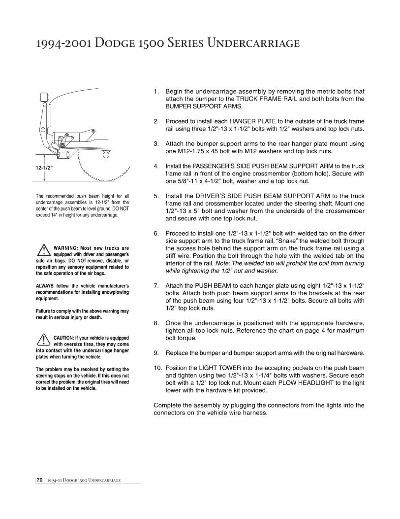
70 1994-01 Dodge 1500 Undercarriage
1994-2001 Dodge 1500 Series Undercarriage
12-1/2"
WARNING: Most new trucks areequipped with driver and passenger’s
side air bags. DO NOT remove, disable, orreposition any sensory equipment related tothe safe operation of the air bags.
ALWAYS follow the vehicle manufacturer’srecommendations for installing snowplowingequipment.
Failure to comply with the above warning mayresult in serious injury or death.
CAUTION: If your vehicle is equippedwith oversize tires, they may come
into contact with the undercarriage hangerplates when turning the vehicle.
The problem may be resolved by setting thesteering stops on the vehicle. If this does notcorrect the problem, the original tires will needto be installed on the vehicle.
The recommended push beam height for allundercarriage assemblies is 12-1/2" from thecenter of the push beam to level ground. DO NOTexceed 14" in height for any undercarriage.
1. Begin the undercarriage assembly by removing the metric bolts thatattach the bumper to the TRUCK FRAME RAIL and both bolts from the BUMPER SUPPORT ARMS.
2. Proceed to install each HANGER PLATE to the outside of the truck framerail using three 1/2"-13 x 1-1/2" bolts with 1/2" washers and top lock nuts.
3. Attach the bumper support arms to the rear hanger plate mount usingone M12-1.75 x 45 bolt with M12 washers and top lock nuts.
4. Install the PASSENGER’S SIDE PUSH BEAM SUPPORT ARM to the truckframe rail in front of the engine crossmember (bottom hole). Secure withone 5/8"-11 x 4-1/2" bolt, washer and a top lock nut.
5. Install the DRIVER’S SIDE PUSH BEAM SUPPORT ARM to the truckframe rail and crossmember located under the steering shaft. Mount one1/2"-13 x 5" bolt and washer from the underside of the crossmemberand secure with one top lock nut.
6. Proceed to install one 1/2"-13 x 1-1/2" bolt with welded tab on the driverside support arm to the truck frame rail. “Snake” the welded bolt throughthe access hole behind the support arm on the truck frame rail using astiff wire. Position the bolt through the hole with the welded tab on theinterior of the rail. Note: The welded tab will prohibit the bolt from turningwhile tightening the 1/2" nut and washer.
7. Attach the PUSH BEAM to each hanger plate using eight 1/2"-13 x 1-1/2"bolts. Attach both push beam support arms to the brackets at the rearof the push beam using four 1/2"-13 x 1-1/2" bolts. Secure all bolts with1/2" top lock nuts.
8. Once the undercarriage is positioned with the appropriate hardware,tighten all top lock nuts. Reference the chart on page 4 for maximumbolt torque.
9. Replace the bumper and bumper support arms with the original hardware.
10. Position the LIGHT TOWER into the accepting pockets on the push beamand tighten using two 1/2"-13 x 1-1/4" bolts with washers. Secure eachbolt with a 1/2" top lock nut. Mount each PLOW HEADLIGHT to the lighttower with the hardware kit provided.
Complete the assembly by plugging the connectors from the lights into the connectors on the vehicle wire harness.

1994-01 Dodge 1500 Undercarriage 71
Ref. Part Qty. Part DescriptionNo. No.
1A 32037 1 1994-2001 Dodge 1500 Series Undercarriage Assembly (Nos. 1 - 18)
1 32045 1 Passenger’s Side Hanger Plate (1994-2001 Dodge 1500)
2 32014 1 Passenger’s Side Push Beam Support Arm (1994-2001 Dodge 1500, 2500 & 3500)
3 32043 1 36-1/4" Push Beam (1994-2001 Dodge 1500)
3L 61128 1 1-1/2" x 9" Push Beam Decal
4 32038 1 Driver’s Side Hanger Plate (1994-2001 Dodge 1500)
5 32017 1 Driver’s Side Push Beam Support Arm (1994-2001 Dodge 1500, 2500 & 3500)
6 39034 1 Light Tower, Round Mounting Tube - Model 760LD
7 61057 2 1/2"-13 x 1-1/4" Grade 8 YZ Hex Head Cap Screw
8 61026 10 1/2", 1-1/16" O.D., 17/32" I.D. YZ SAE Mil-Carb High-Strength Washer
9 61020 22 1/2"-13 Grade C Z Top Lock Nut
10 61055 18 1/2"-13 x 1-1/2" Grade 8 YZ Hex Head Cap Screw
11 61151 1 1/2"-13 x 1-1/2" Grade 8 YZ Hex Head Cap Screw with Welded Tab
12 61075 1 1/2"-13 x 5" Grade 8 YZ Hex Head Cap Screw
13 61065 1 5/8"-11 x 4-1/2" Grade 8 YZ Hex Cap Screw
14 61064 1 5/8", 1-5/16" O.D., 21/32" I.D., YZ SAE Mil-Carb High-Strength Washer
15 61063 1 5/8"-11 Grade C Z Top Lock Nut
16 61068 2 M12-1.75 x 45 Grade 8.8 Z Hex Head Cap Screw
17 61070 2 M12 I.D., 24 O.D. Z Flat Washer
18 61271 2 M12-1.75 Class C Top Lock Nut
N/A 61078 1 1994-2001 Dodge 1500, 2500 & 3500 Series Hardware Kit - Kit Includes: Nos. 7 - 18
1 9 9 4 - 2 0 0 1 D O D G E 1 5 0 0 S E R I E S U N D E R C A R R I AG E PA R T S L I S T
8
9
7
6
9
7
8
3L
2
3
1A1
4
9
9
9
8
8
9
10
10 10
1010
109
10
9
13
14 15
16
1718
16
17
18
5
10
9
11
89
8
9
12
Note: The reference numbers listed identify parts shown in the illustration above. These numbers are specific to this illustration only and do not correspond with otherdiagrams in the manual. Always review the part number given for proper component identification.

72 1994-01 Dodge 2500 & 3500 Undercarriage
1994-2001 Dodge 2500 & 3500 Series Undercarriage
12-1/2"
WARNING: Most new trucks areequipped with driver and passenger’s
side air bags. DO NOT remove, disable, orreposition any sensory equipment related tothe safe operation of the air bags.
ALWAYS follow the vehicle manufacturer’srecommendations for installing snowplowingequipment.
Failure to comply with the above warning mayresult in serious injury or death.
CAUTION: If your vehicle is equippedwith oversize tires, they may come
into contact with the undercarriage hangerplates when turning the vehicle.
The problem may be resolved by setting thesteering stops on the vehicle. If this does notcorrect the problem, the original tires will needto be installed on the vehicle.
The recommended push beam height for allundercarriage assemblies is 12-1/2" from thecenter of the push beam to level ground. DO NOTexceed 14" in height for any undercarriage.
1. Begin the undercarriage assembly by removing the metric bolts thatattach the bumper to the TRUCK FRAME RAIL and both bolts from the BUMPER SUPPORT ARMS.
2. Proceed to install each HANGER PLATE to the outside of the truck framerail using three 1/2"-13 x 1-1/2" bolts with 1/2" washers and top lock nuts.
3. Attach the bumper support arms to the rear hanger plate mount usingone M12-1.75 x 45 bolt with M12 washers and top lock nuts.
4. Install the PASSENGER’S SIDE PUSH BEAM SUPPORT ARM to the truckframe rail in front of the engine crossmember (bottom hole). Secure withone 5/8"-11 x 4-1/2" bolt, washer and a top lock nut.
5. Install the DRIVER’S SIDE PUSH BEAM SUPPORT ARM to the truckframe rail and crossmember located under the steering shaft. Mount one1/2"-13 x 5" bolt and washer from the underside of the crossmemberand secure with one top lock nut.
6. Proceed to install one 1/2"-13 x 1-1/2" bolt with welded tab on the driverside support arm to the truck frame rail. “Snake” the welded bolt throughthe access hole behind the support arm on the truck frame rail using astiff wire. Position the bolt through the hole with the welded tab on theinterior of the rail. Note: The welded tab will prohibit the bolt from turningwhile tightening the 1/2" nut and washer.
7. Attach the PUSH BEAM to each hanger plate using eight 1/2"-13 x 1-1/2"bolts. Attach both push beam support arms to the brackets at the rearof the push beam using four 1/2"-13 x 1-1/2" bolts. Secure all bolts with1/2" top lock nuts.
8. Once the undercarriage is positioned with the appropriate hardware,tighten all top lock nuts. Reference the chart on page 4 for maximumbolt torque.
9. Replace the bumper and bumper support arms with the original hardware.
10. Position the LIGHT TOWER into the accepting pockets on the push beamand tighten using two 1/2"-13 x 1-1/4" bolts with washers. Secure eachbolt with a 1/2" top lock nut. Mount each PLOW HEADLIGHT to the lighttower with the hardware kit provided.
Complete the assembly by plugging the connectors from the lights into the connectors on the vehicle wire harness.
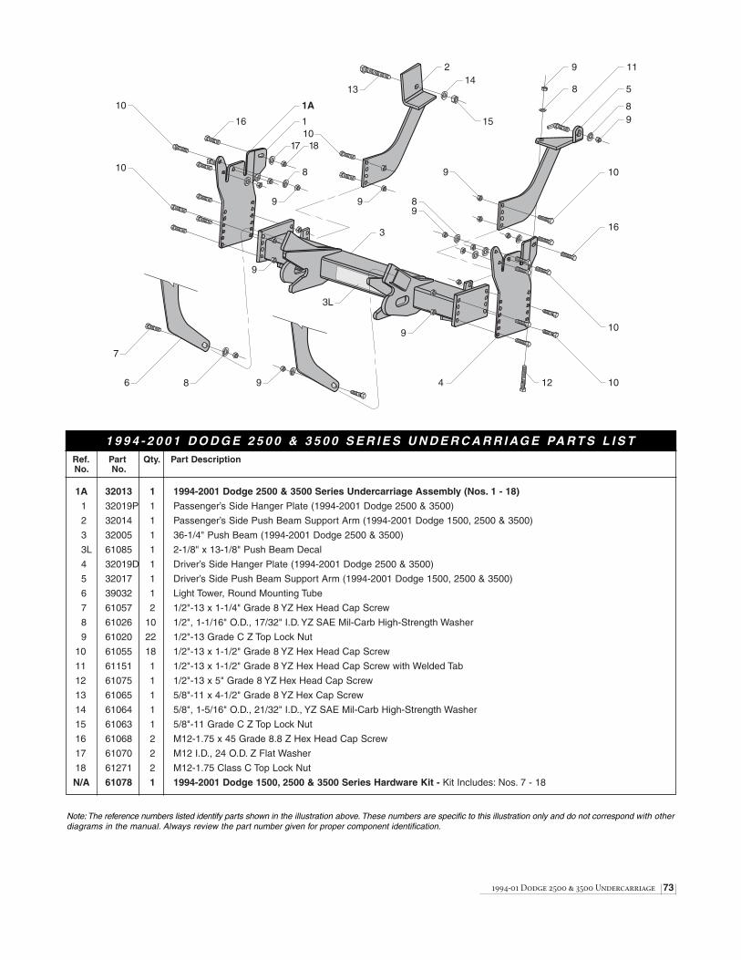
1994-01 Dodge 2500 & 3500 Undercarriage 73
Ref. Part Qty. Part DescriptionNo. No.
1A 32013 1 1994-2001 Dodge 2500 & 3500 Series Undercarriage Assembly (Nos. 1 - 18)
1 32019P 1 Passenger’s Side Hanger Plate (1994-2001 Dodge 2500 & 3500)
2 32014 1 Passenger’s Side Push Beam Support Arm (1994-2001 Dodge 1500, 2500 & 3500)
3 32005 1 36-1/4" Push Beam (1994-2001 Dodge 2500 & 3500)
3L 61085 1 2-1/8" x 13-1/8" Push Beam Decal
4 32019D 1 Driver’s Side Hanger Plate (1994-2001 Dodge 2500 & 3500)
5 32017 1 Driver’s Side Push Beam Support Arm (1994-2001 Dodge 1500, 2500 & 3500)
6 39032 1 Light Tower, Round Mounting Tube
7 61057 2 1/2"-13 x 1-1/4" Grade 8 YZ Hex Head Cap Screw
8 61026 10 1/2", 1-1/16" O.D., 17/32" I.D. YZ SAE Mil-Carb High-Strength Washer
9 61020 22 1/2"-13 Grade C Z Top Lock Nut
10 61055 18 1/2"-13 x 1-1/2" Grade 8 YZ Hex Head Cap Screw
11 61151 1 1/2"-13 x 1-1/2" Grade 8 YZ Hex Head Cap Screw with Welded Tab
12 61075 1 1/2"-13 x 5" Grade 8 YZ Hex Head Cap Screw
13 61065 1 5/8"-11 x 4-1/2" Grade 8 YZ Hex Cap Screw
14 61064 1 5/8", 1-5/16" O.D., 21/32" I.D., YZ SAE Mil-Carb High-Strength Washer
15 61063 1 5/8"-11 Grade C Z Top Lock Nut
16 61068 2 M12-1.75 x 45 Grade 8.8 Z Hex Head Cap Screw
17 61070 2 M12 I.D., 24 O.D. Z Flat Washer
18 61271 2 M12-1.75 Class C Top Lock Nut
N/A 61078 1 1994-2001 Dodge 1500, 2500 & 3500 Series Hardware Kit - Kit Includes: Nos. 7 - 18
1A
1
3
2
4
5
6
7
8 9
10
10
10
10
10
10
11
12
13
15
148
9
8
9
9
9
989
9
89
3L
17
16
18
16
Note: The reference numbers listed identify parts shown in the illustration above. These numbers are specific to this illustration only and do not correspond with otherdiagrams in the manual. Always review the part number given for proper component identification.
1 9 9 4 - 2 0 0 1 D O D G E 2 5 0 0 & 3 5 0 0 S E R I E S U N D E R C A R R I AG E PA R T S L I S T

74 Troubleshooting Guide (1 of 2)
Problem Probable Cause(s) Suggested Remedy
Pump will not run. Plow wire harness and vehicle wire harness may not be Verify the wire harness is properly connected. Review properly connected. the instruction on pages 9-11.
Ground cables to the battery, manifold or solenoid may Properly connect all cables. Clean and lubricate withnot be properly connected. white lithium grease.
Pump will not run, no power to the solenoid. The red, power wire and brown (or brown/white), activation Properly connect both cables. Test for power bywire on the solenoid are not properly connected. init iating any joystick function except the float.
Note: The POWER rocker switch must be in the “ON”position to properly test any plow function. No power,diagnose plow & truck wire harnesses.
Pump will not run with power to the solenoid. The red, hot wire to the pump motor is not properly Connect red wire. If problem is not resolved, the connected. solenoid could be seized or the pump motor may be
worn. Replace solenoid.
Pump will not turn off. Pump solenoid may be damaged. Disconnect the brown activation wire from the solenoid.If the problem is not resolved, replace the solenoid.
Short in the joystick control or wire harness. Disconnect the joystick in the cab. If the solenoidturns off, there is a short in the electrical system.
Pump runs but plow functions are slow. Fluid level in the pump reservoir is low. Fluid is leaking. Add fluid to within 3/4” from the top of the tank. Check for leaks around the pump, manifold and cylinders.
System pressure may be set too low. Adjust the pressure. Remove the hex cap on top of the pump and turn the screw clockwise 1/8 turn. Propersystem pressure should be set at 1800 PSI. Testfunctions and repeat procedure as needed.
Voltage from the vehicle’s alternator is too low. Repair or replace vehicle alternator. Voltage must be no less than 11.8 volts.
Pump filter may be clogged. Remove the pump tank and thoroughly clean the filter.
A-frame latch will not move. Draw latch is binding the A-frame latch. Lift the draw latch to relieve binding on the A-frame latch and reposition the A-frame latch as needed.
Plow will not lift. Pump works properly. Control station in the cab may not be properly connected. Connect the power connector from the control to the vehicle wire harness.
A-frame latch is in the (down) locked position. Lift the A-frame latch into the raised position.
Solenoid may be damaged. Remove both S6 & S7 solenoids from the cartridgevalves. Position a screwdriver inside of the solenoid and push the draw latch connect/disconnect toggle switch upward. The solenoid should be magnetically drawn tothe screwdriver. Replace solenoid if there is no action.
Troubleshooting Guide
Prior to diagnosing your straight blade, verify that all connectors (plow and vehicle wire harness plugs, headlight adapters,control box, fused hot lead, draw latch switch, solenoid ground wire connection, coil wire lead harness, plow headlightharnesses) are free of corrosion and are well lubricated with white lithium grease. Insuring that all connectors are in goodworking order will save time in determining your snowplow’s service needs.

Troubleshooting Guide (2 of 2) 75
Angle Pressure Relief Valve
Variable Flow Control Valve Valve
Jam Nut Variable FlowControl Valve
Problem Probable Cause(s) Suggested Remedy
Hydraulic lock in the manifold. Loosen cartridge valve S6 or S7 to relieve pressure andretighten. DO NOT OVERTIGHTEN!
Solenoid cartridge valve may be contaminated. Remove any foreign objects that may be obstructingproper valve operation. Replace if not operating properlyafter cleaning.
Plow will not stay angled when plowing. The angle pressure relief valve is set too low. Follow the guidelines indicated above; however, the PSI NOTE: Increasing the pressure relief valve will cause setting should not exceed 3000 PSI.damage to your plow. Do not set the pressure reliefgreater than 3000 PSI (See illustration below)
Plow will not angle, pump works. Review all probable causes above. NOTE: Verify solenoids S3 & S4 for angle functions.
Plow lowers too slow. Variable flow control valve is not adjusted properly. Turn flow control valve counterclockwise in small(See illustration below) increments and test. NOTE: Never make adjustments
when the plow is in the raised position! Fluid pressurewill make the valve difficult to adjust and serious injury or death can occur from a falling plow.
Should your snowplow develop other problems not indicated in the Troubleshooting Guide, contact your local dealer for technical assistance and/or replacement parts.Technical support can also be obtained calling our Customer Service Department toll free at 1-888-680-8600, Monday - Friday, 8AM - 5PM EST.

BLIZZARD®
LIMITED CONSUMER WARRANTYThis warranty covers defects in material and workmanship except as set forth below.
WARRANTED PARTY:This warranty applies only to the “Original Purchaser” who purchased this plow from an Authorized Blizzard Dealer,
for personal, family or household use.
TERM OF WARRANTY:This Blizzard straight blade snowplow is warranted for the following period:
Parts and labor are warranted for one year from date of purchase.
BLIZZARD CORPORATION’S WARRANTY REMEDY:Blizzard Corporation will, at its sole discretion, repair or replace defective parts at no charge.
CUSTOMERS RESPONSIBILITY:To obtain warranty service, the purchaser must return the defective snowplow to any Authorized Blizzard Dealer.
The purchaser must verify the original purchase date. Transportation costs to and from the dealer will be the responsibility of the purchaser.
ITEMS NOT COVERED UNDER THIS WARRANTY:This limited warranty does not cover the following:
1. Expendable parts such as cutting edges, plow shoes, hoses, fasteners, blade guides, paint finish, etc.
2. Any snowplow or part thereof which has been repaired or altered by anyone other than an Authorized Blizzard Dealer.
3. Any snowplow or part thereof which has been subject to neglect, misuse, accident, improper installation, maintenance,or storage. This includes, but is not limited to, corrosion of any electrical components.
4. Snowplows mounted on vehicles other than those for whom Blizzard Corporation has provided a specific undercarriage system.
5. Blizzard Corporation does not assume liability for damage to the purchaser's vehicle resulting from the attachmentand use of a Blizzard straight blade snowplow. Vehicle risk is the sole responsibility of the purchaser.
WARRANTY LIMITATIONS:THIS WARRANTY IS OFFERED IN LIEU OF ANY OTHER EXPRESS WARRANTY.
THE DURATION OF ALL IMPLIED WARRANTIES, INCLUDING BUT NOT LIMITED TO THE IMPLIED WARRANTIES OF MERCHANTABILITY AND FITNESS FOR A PARTICULAR PURPOSE, ARE LIMITED
TO THE DURATION OF THIS WARRANTY.
BLIZZARD CORPORATION'S LIABILITY IS EXPRESSLY LIMITED TO REPAIR OR REPLACEMENT OF DEFECTIVE PARTS. BLIZZARD CORPORATION SHALL NOT BE LIABLE FOR CONSEQUENTIAL, INCIDENTALOR CONTINGENT DAMAGES WHATSOEVER, EVEN IF DAMAGES ARE CAUSED BY THE NEGLIGENCE OR
FAULT OF BLIZZARD CORPORATION.
State Laws: Some states do not allow exclusion of incidental or consequential damages or the limitations on howlong an implied warranty lasts, so these limitations or exclusions may not apply to you. This warranty gives you
specific legal rights and you may also have other rights which vary from state to state.
This warranty does not apply if you purchased your snowplow for other than personal, family, or household use. Ifpurchased for other than personal, family or household use, refer to the Blizzard Straight Blade Commercial Warranty.
95 AIRPARK BOULEVARD CALUMET, MICHIGAN 49913 [906] 482-5555
1029-7-99 REV 8/01

COMMERCIAL WARRANTYThis warranty covers defects in material and workmanship except as set forth below.
WARRANTED PARTY:
This warranty applies only to the “Original Purchaser” who purchased this plow from an Authorized Blizzard Dealer,for commercial use.
TERM OF WARRANTY:
This Blizzard straight blade snowplow is warranted for the following period:Parts and labor are warranted for one year from date of purchase.
BLIZZARD CORPORATION’S WARRANTY REMEDY:
Blizzard Corporation will, at its sole discretion, repair or replace defective parts at no charge.
CUSTOMERS RESPONSIBILITY:
To obtain warranty service, the purchaser must return the defective snowplow to any Authorized Blizzard Dealer within thewarranty period. The purchaser must verify the original purchase date. Transportation costs to and from the Dealer will be
the responsibility of the purchaser.
ITEMS NOT COVERED UNDER THIS WARRANTY:
This warranty does not cover the following:
1. Expendable parts such as cutting edges, plow shoes, hoses, fasteners, blade guides, paint finish, etc.
2. Any snowplow or part thereof which has been repaired or altered by anyone other than an Authorized Blizzard Dealer.
3. Any snowplow or part thereof which has been subject to neglect, misuse, accident, improper installation, maintenance,or storage. This includes, but is not limited to, corrosion of any electrical components.
4. Snowplows mounted on vehicles other than those for whom Blizzard Corporation has provided a specific undercarriagesystem.
5. Blizzard Corporation does not assume liability for damage to the purchaser's vehicle resulting from the attachment anduse of a Blizzard straight blade snowplow. Vehicle risk is the sole responsibility of the purchaser.
LIMITS OF BLIZZARD CORPORATION’S LIABILITIES:
BLIZZARD CORPORATION'S LIABILITY IS EXPRESSLY LIMITED TO REPAIR OR REPLACEMENT OF DEFECTIVE PARTS. BLIZZARD CORPORATION SHALL NOT BE LIABLE FOR CONSEQUENTIAL, INCIDENTAL OR CONTINGENT DAMAGES WHATSOEVER, EVEN IF DAMAGES ARE CAUSED BY THE NEGLIGENCE OR
FAULT OF BLIZZARD CORPORATION.
THE FOREGOING WARRANTIES ARE EXCLUSIVE AND IN LIEU OF ALL OTHER EXPRESSED AND IMPLIED WARRANTIES INCLUDING, BUT NOT LIMITED TO, THE IMPLIED WARRANTIES OF MERCHANTABILITY AND
FITNESS FOR A PARTICULAR PURPOSE.
This warranty does not apply if you purchased your snowplow for personal, family, or household use.In this case, refer to the Blizzard Straight Blade Limited Consumer Warranty.
BLIZZARD®
95 AIRPARK BOULEVARD CALUMET, MICHIGAN 49913 [906] 482-5555
1030-7-99 REV 8/01

95 Airpark BoulevardCalumet,MI 49913[888] 680-8600[906] 482-5555[906] 482-5445 Faxwww.blizzardplows.com
Blizzard, WidePass, BucketBlade and Seat Cinch are trademarks ofBlizzard Corporation. Blizzard is registered in the United States Patent and Trademark Office. Blizzard straight blade snowplows are protectedby U.S. patent 6,276,076.Other patents pending.Copyright © 2001 BlizzardCorporation. All rights reserved.1214-7-01 Made and printed in the USA.
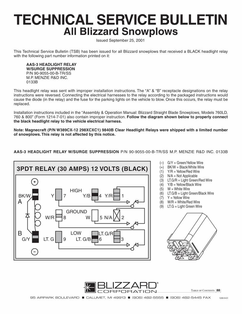
Table of Contents 88
TECHNICAL SERVICE BULLETINAll Blizzard Snowplows
This Technical Service Bulletin (TSB) has been issued for all Blizzard snowplows that received a BLACK headlight relaywith the following part number information printed on it:
AAS-3 HEADLIGHT RELAYW/SURGE SUPPRESSIONP/N 90-9055-00-B-TR/SSM.P. MENZIE R&D INC.0133B
This headlight relay was sent with improper installation instructions. The “A” & “B” receptacle designations on the relayinstructions were reversed. Connecting the electrical harnesses to the relay according to the packaged instructions wouldcause the diode (in the relay) and the fuse for the parking lights on the vehicle to blow. Once this occurs, the relay must bereplaced.
Installation instructions included in the “Assembly & Operation Manual: Blizzard Straight Blade Snowplows, Models 760LD,760 & 800” (Form 1214-7-01) also contain improper instruction. Follow the diagram shown below to properly connectthe black headlight relay to the vehicle electrical harness.
Note: Magnecraft (P/N W389CX-12 298XCXC1) 9840B Clear Headlight Relays were shipped with a limited numberof snowplows. This relay is not affected by this notice.
AAS-3 HEADLIGHT RELAY W/SURGE SUPPRESSION P/N 90-9055-00-B-TR/SS M.P. MENZIE R&D INC. 0133B
95 AIRPARK BOULEVARD CALUMET, MI 49913 [906] 482-5555 [906] 482-5445 FAX 1230-9-01
Issued September 25, 2001
A
BG/Y
BK/W Y 7
W/R 8
LT. G 9
HIGH
GROUND
LOW
Y/B 4
W 5
Y/R 1
LT. G/B 6LT. G/R
3
3PDT RELAY (30 AMPS) 12 VOLTS (BLACK)
N/A 2
(–) G/Y = Green/Yellow Wire(+) BK/W = Black/White Wire(1) Y/R = Yellow/Red Wire(2) N/A = Not Applicable(3) LT.G/R = Light Green/Red Wire(4) Y/B = Yellow/Black Wire(5) W = White Wire(6) LT.G/B = Light Green/Black Wire(7) Y = Yellow Wire(8) W/R = White/Red Wire(9) LT.G = Light Green Wire