assembly and commissioning instructions softstarters vs - 17.. · motor voltage increases according...
TRANSCRIPT

e l e c t r o n i c
Quality is our Drive.
Assembly and Commissioning InstructionsSoftstartersVS ... - 17...45

VS II ...-17 ... 45 1
as per 07/10 15700.10005
Table of Contents Page
1. Safety notes 3
2. Conformity 3
3. General description 4
4. Usage to the intended purpose 4
5. EC Declaration of Conformity 5
6. Block diagram 6
7. Commissioning 67.1 Mounting instructions 67.2 Connection 87.3 Parameter settings 9
8. LED indicators 118.1 Option „M“ 11
9. Fault 129.1 Fault description 129.2 Fault remedy 139.3 Resetting of faults 13
10. Technical data (standard)* 1410.1 Environmental conditions 15
11. Dimensioning rules 1511.1 Dimensioning of pre-fuses 1511.2 Determining the permissible starting frequency 17
12. Special units 2012.1 Devices with rated voltage of 230V or 480V 2012.2 Devices featuring a wide-voltage-range power section 2012.3 Devices featuring special voltage >= 500V 2012.4 Devices with motor-PTC input 20
13. Installation guideline 2213.1 Connection 2213.1.1 Earthing 2213.1.2 Cabling 2213.2 General connection diagram 2413.3 Typical connections 2513.4 Motor/Soft start in delta connection (only units with option „M“) 2613.5 Wide-voltage-range connection 27

2 VS II ...-17 ... 45
14. Dimensions 28
15. Special units 28
Notes and symbols used in these instructions
Note: Notes explain the advantages of certain adjustments or settings and help you to make use of the device in the best possible way.
Warning notices: Read them carefully and follow them strictly!
Warning notices are indicated in order to protect you against danger or to help you to prevent the device from being damaged.
Caution: Danger to life through electric shock!
When you see this sign, always make sure that the device is de-energized and secured against unintentional energizing.
These commissioning instructions were prepared with great care. Nevertheless, AdvancedControl does not assume liability for damage resulting from mistakes possibly contained in this manual. Technical changes that serve to improve the product are subject to change without notice.

VS II ...-17 ... 45 3
1. Safety notesThe described devices are electrical equipment for use in industrial electrical power installations. An impermissible removal of the covers during operation can cause serious damage to your health, since these devices contain live parts with high voltages.
Adjustment work may only be performed by trained staff observing the safety regulations. Assembly and mounting work may only be carried out with the equipment deenergized.Make sure that all drive components are properly earthed.Please read these commissioning instructions carefully before putting the device into operation.Besides, the user must ensure that the devices and associated components are fitted and connected in accordance with the appliable local, legal and technical regulations. The VDE-regulations VDE 0100, VDE 0110 (EN 60664), VDE 0160 (EN 50178) , VDE 0113 (EN 60204, EN 61310),VDE 0660 (EN 50274) plus the appropriate regulations of the TÜV (Technical Control Association) and the trade associations apply in Germany.The user must ensure that the drive turns into a safe operating state following a device failure, in the event of maloperation, or if the control unit has failed etc..Caution: Even if the motor is at rest, it is not physically separated from the mains.
2. ConformityIn industrial linguistic usage the drive controllers of the type series VersiStart II are called "devices", however, in the sense of the "law on the safety of equipment", the "EMC-law" or the "EC-maschinery directive" they are not devices or machines ready for use or connection but they are components. It is only possible to define their final function, when these components are integrated into the design and construction of the user.
To be able to use the devices to their intended purpose, it requires power supply networks according to DIN EN 50160 (IEC38).The user takes the responsibility that the user’s design and construction comply with the appli-cable legal provision. The commissioning is strictly forbidden as long as the conformity of the final product with the guidelines 2006/42/EC (Machinery directive) and 2006/95/EC (Low voltage directive) is not proved.
4 VS II ...-17 ... 45
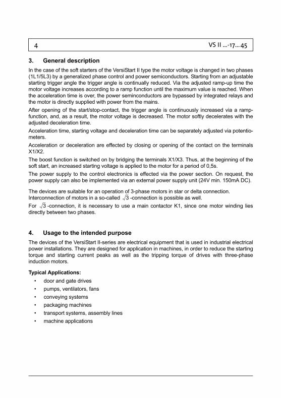
3. General descriptionIn the case of the soft starters of the VersiStart II type the motor voltage is changed in two phases (1L1/5L3) by a generalized phase control and power semiconductors. Starting from an adjustable starting trigger angle the trigger angle is continually reduced. Via the adjusted ramp-up time the motor voltage increases according to a ramp function until the maximum value is reached. When the acceleration time is over, the power seminconductors are bypassed by integrated relays and the motor is directly supplied with power from the mains.After opening of the start/stop-contact, the trigger angle is continuously increased via a ramp-function, and, as a result, the motor voltage is decreased. The motor softly decelerates with the adjusted deceleration time.Acceleration time, starting voltage and deceleration time can be separately adjusted via potentio-meters.Acceleration or deceleration are effected by closing or opening of the contact on the terminals X1/X2.The boost function is switched on by bridging the terminals X1/X3. Thus, at the beginning of the soft start, an increased starting voltage is applied to the motor for a period of 0,5s.The power supply to the control electronics is effected via the power section. On request, the power supply can also be implemented via an external power supply unit (24V min. 150mA DC).
The devices are suitable for an operation of 3-phase motors in star or delta connection. Interconnection of motors in a so-called -connection is possible as well.For -connection, it is necessary to use a main contactor K1, since one motor winding lies directly between two phases.
4. Usage to the intended purposeThe devices of the VersiStart II-series are electrical equipment that is used in industrial electrical power installations. They are designed for application in machines, in order to reduce the starting torque and starting current peaks as well as the tripping torque of drives with three-phase induction motors.
Typical Applications:• door and gate drives• pumps, ventilators, fans• conveying systems• packaging machines• transport systems, assembly lines• machine applications
33

VS II ...-17 ... 45 5
5. EC Declaration of Conformity
EC Declaration of Conformity
Name / Address: Peter Electronic GmbH & Co.KG Bruckäcker 9 92348 Berg
Germany
hereby declares that the following product (device, component, unit) in the version as supplied
Product designation: Softstarter Serien / type designation: VS II 230...690-17...45; B; M; UL; D; H Article group: 257... Year of manufacture: 2005 complies with the provisions of the following EC-directives: 2004/108/EG concerning Electromagnetic compatibility
and 2006/95/EG concerning Electrical equipment designed for use within certain voltage limits
The following harmonized standards have been applied: EN 60947-1: Low-voltage switchgear and 2008 controlgear
General rules
EN 60947-4-2: Low-voltage switchgear and 2007 controlgear Contactors and motor-starters - AC semiconductor motor controllers and starters
This EC Decleration of Conformity is no longer valid, if the products is modified or changed without our agreement. This declaration is issued under the sole responsibility of the signatory.
Berg, 05.08.2009 Dr. Thomas Stiller, Managing Director (place, date)
(signatory and function of the signatory)
(signature)
The manufacturer / company placing the product on the market (authorized representatives of the manufacturer / companies placing the product on the market that are established within the Community)

6 VS II ...-17 ... 45
6. Block diagram
7. CommissioningThe device is to be put into operation in 3 steps:
1. Mounting2. Connection and3. Parameter setting
Note:
Please notice the max. permissible starting current (under 7/Technical data).
7.1 Mounting instructions
Caution: Danger to life through electric shock!
The following conditions are to be complied with in order to ensure a safe and reliable operation of the VersiStart II.
1. The device series VersiStart II is to be used under conditions of the overvoltage category III.
2. Make sure that pollution degree 2 or better, in accordance DIN EN60644-1 / IEC664, is complied with.
supplyvoltage
Triggerpulse
generator
6T32T1 4T2
Controlfor
bypass
5L31L1 3L2
Electronics
Rampcontrol
Start
U start
X8
X7RA2
t acc t dec
X3
X2
Boost
X6
X5RA1
X1
X4control supply U 24VDCat option "B"
+s

VS II ...-17 ... 45 7
3. The device has to be installed into a housing (min. degree of protection: IP54). Please take care of a sufficient heat dissipation.
4. The device must be operated without being exposed to contamination by water, oil, carbon deposits, dust, etc..
5. Insert in North America, UL and CSA-listed.5.1 ’Suitabe For Use On A Circuit Capable Of Delivering Not More Then 5kA rms
Symmetrical Amperes, 600 Volts Maximum’ and ’When Protected by A Circuit Breaker type N2MB2-AF63-NA 63A, 600 Volts Maximum.’
5.2 ’Use Copper Conductors 60/75°C, or 75°C only.’Place the device vertically on a perpendicular mounting plate with the motor terminals pointing downwards. The device is to be snap-mounted onto a 35mm top-hat rail according to DIN EN 50022. Underneath the device, no additional heat sources such as heating resistors must be mounted or arranged.
Warning:
To avoid heat concentrations, a distance of at least 40mm is to be kept between cable duct and device.
Clearance X
Under normal drive conditions, the devices can be mounted side by side.In the case of applications requiring high starting frequencies and / or high-inertia starting, the devices should be mounted with a distance of approx. 10mm in between them, in order to ensure good ventilation of the heat sink.
On
Bypass
versi start II
12345678
0100%
0100%
0100%t
t
UStart
X
min. 40mm
min. 40mm

8 VS II ...-17 ... 45
7.2 Connection
Power section (see also connection diagram)
Control section
The input resistance of the control inputs is 10kOhm. To control them, it is necessary to use switching contacts enabling reliable switching of the lower control currents (e.g., AgNi+Au)!If the contact on the terminals X1 a. X2 is closed, the motor accelerates with the adjusted accele-ration time ramp. When the contact is open, the motor decelerates with the adjusted deceleration time ramp.
Caution: Danger to life through electric shock!
The motor is not physically separated from the mains.
Alternatively, the device can also be controlled with d.c. voltage.If only soft starts are required, VersiStart II may also be controlled via the main contactor. For this purpose, the terminals X1 and X2 have to be bridged.
Adjusting the control typeDevices of the VersiStart II series may be controlled by two types of control.
1. Control with a switching contact or switching transistor between terminal X1 and X2.2. Control by d.c. voltage 10 … 24VDC between terminals X2 and X4.
Control supply voltage US only in the case of wide-voltage devices (option B)
Between the terminals X1 (+) and X4 ( ) an auxiliary voltage of 24VDC ±10%/150mA is to be injected.
Terminal 1L1:Terminal 3L2:Terminal 5L3:Earth connectionTerminal 2T1:Terminal 4T2:Terminal 6T3:
Mains voltage L1Mains voltage L2Mains voltage L3PEMotor terminal UMotor terminal VMotor terminal W
X2
Start/StopControl terminals
+
X1 X3 X4
RA 1 RA 2Boost
Fault Devicebypassed
X5 X6 X7 X8
VS II ...-17 ... 45 9
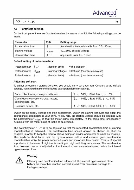
7.3 Parameter settings
On the front panel there are 3 potentiometers by means of which the following settings can be made.
Default setting of potentiometers:
Adjusting soft startTo adjust an optimum starting behavior, you should carry out a test run. Contrary to the default settings, you should make the following basic potentiometer-settings.
Switch on the supply voltage and start acceleration. Watch the starting behavior and adapt the approporiate parameters to your drive. At any rate, the starting voltage should be adjusted with the potentiometer UStart so that the motor starts immediately. At the same time, unnecessary humming with the motor being at rest is to be avoided.
The potentiometer is to be adjusted so that the requested acceleration time or starting characteristics is achieved. The acceleration time should always be chosen as short as possible, in order to keep the thermal stress acting on device and motor as small as possible. This leads to short times until the bypass relays pull in and ensures good acceleration characteristics while the power semiconductors and motor are less heated. This is of special importance in the case of high-inertia starting or high switching frequencies. The acceleration time, however, has to be adjusted so that the motor reaches nominal speed before the internal bypass relays close.
Warning:
If the adjusted acceleration time is too short, the internal bypass relays close before the motor has reached nominal speed. This can cause damage to the bypass relays.
Parameter Poti Setting rangeAcceleration time Acceleration time adjustable from 0.5...10sec
Starting voltage UStart 40…80% of rated voltage
Deceleration time adjustable from 0.5...10sec
Potentiometer (acceler. time) = mid-position
Potentiometer UStart (starting voltage) = left stop (counter-clockwise)
Potentiometer (deceler. time) = left stop (counter-clockwise)
Fans, roller tracks, conveyor belts, etc. 50%, UStart 0%, 0%
Centrifuges, conveyor screws, mixers,compressors, etc.
50%, UStart 50%, 50%
Pressure pumps, etc. 50%, UStart 50%, 50%

10 VS II ...-17 ... 45
Adjusting soft stop
Note: Soft stop is only useful for pump drives or applications in the case of which the drive comes to a stop immediately after switch off. In the case of drives driving high-inertia loads, soft stop is not sensible.
Note: To enable soft stop, the VersiStart II, during the deceleration phase, has to be supplied with power from the supply mains.
In the case of these devices, the cut-off voltage is factory-set to 70%.
The potentiometer is to be adjusted so that the requested deceleration time or deceleration characteristic is reached.
Caution: Danger to life through electric shock!
Even if the motor is at rest, it is not physically separated from the mains.
Warning!
Make sure that the specified switching frequency is not exceeded!

VS II ...-17 ... 45 11
8. LED indicatorsOn the device front panel there are 2 light-emitting diodes indicating the following operational states.
On the control terminals X5 / X6 (RA 1) and X7 / X8 (RA 2) two signaling relays are available which signal the following operational states:
8.1 Option „M“
The signaling contact RA 2 will be closed when acceleration is started. After decelleration is finished the signaling contact will be opened again.
LED Operational statusGreen Device is connected to mains voltage
Yellow Start completed, device bypassed
Yellow - flashing with increasing or decreasing frequency
Soft start / Soft stop
Yellow - flashing with constant frequency
Fault
RA 1 Fault.Under normal operating conditions the signaling contact RA 1 is closed, it only opens if a fault occurs.
RA 2 Device bypassed.When the start-up ramp is over and the motor is supplied with nominal voltage or the bypass relays are closed, the signaling contact RA 2 will be closed.

12 VS II ...-17 ... 45
9. FaultThe device series VersiStart II monitors various fault conditions. If a fault is detected, the device signals the fault with the yellow LED (flashing at constant frequency). In the case of a fault, the signaling relay RA 1 is opened. The various fault conditions are indicated via different flashing frequencies of the yellow LED.
9.1 Fault description
Fault LED Operational status1 Yellow LED flashing 2x repeatedly
with a short pauseHeat sink temperature is too high/device is thermally overloaded, or in the case of devices with motor PTC (see 12.4) the motor temperature is too high.
2 Yellow LED flashing 3x repeatedly with a short pause
Electronics fault
3 Yellow LED flashing 4x repeatedly with a short pause
Mains phase failure / Trigger failure in phase 1
4 Yellow LED flashing 5x repeatedly with a short pause
Mains phase failure / Trigger failure in phase 3
5 Yellow LED flashing 6x repeatedly with a short pause
Motor phase failure / Power semiconductor(s) defective in phase 1
6 Yellow LED flashing 7x repeatedly with a short pause
Motor phase failure/ Power semiconductor(s) defective in phase 3
7 Yellow LED flashing 8x repeatedly with a short pause
General synchronization error/Mains or motor circuit defective

VS II ...-17 ... 45 13
9.2 Fault remedy
In case of a fault, please proceed as follows:
9.3 Resetting of faults
To reset a device failure, it is necessary to disconnect the device from the supply voltage. After the cause of the fault has been remedied by trained expert personnel, the supply voltage can be reconnected. The device works again under normal service conditions.Devices with option B (wide-voltage-range power section) must be reset by disconnect the control supply voltage US on the terminals X1 and X4.
Fault 1: Check the frequency of starts and the starting current and also observe the max. ambient temperature. Give the device and/or the motor enough time between starts to cool down. The heat dissipation can be improved by forced cooling, e.g., by means of a fan mounted unterneath the device or by using a motor with a sepa-rately driven fan.
Fault 2: Defect in the internal control electronics. Send device to the producer to have it checked.
Fault 3/4: Mains supply is interrupted. Motor lead interrupted, power semiconductor(s) defective, motor defective. Check motor and wiring. Send device to the producer to have it inspected.
Fault 5/6: Mains supply is interrupted. Power semiconductors do not trigger. Motor rating is too small. Check as to whether the motor is suitable for the device rating. Send device to the producer to have it checked.
Fault 7: Mains or motor wiring is interrupted. Power semiconductor(s) defective. Check wiring. Send device to producer to have it inspected.

14 VS II ...-17 ... 45
10. Technical data (standard)*
* For special voltages please see our supplement.
Type designation, VersiStart VS II 400-17 VS II 400.25 VS II 400-32 VS II 400-45Mains / motor voltageacc. to DIN EN 50160 (IEC 38)
400V ±10% 50/60Hz
Control supply voltage US only in the case of option „B“
24VDC ±10%/150mA
max. Motor rating at 380/415V (rated power)
7.5kW 11kW 15kW 22kW
Rated device current (Ie) 17A 25A 32A 45A
max. Power dissipation - in operation - in standby
29.5W 7.5W
29.5W 7.5W
29.5W 7.5W
27W 7.5W
min. Motor load 20% of device rating
Acceleration time 0.5 … 10s
Starting voltage 40 … 80% of rated voltage
Deceleration time 0.5 … 10s
Restart time 200ms
max. Switching frequency at 3x Ie and 5s
50/h 35/h 25/h 10/h
Cross-sect. area for connection: Control terminals Power terminals
1.5mm²6mm²
1.5mm²16mm²
Tigthening torque 1.2-1.5 Nm 11-13 Ibs in
1.5-1.7 Nm 13-15 Ibs in
I²t - Power semiconductors 4900A²s 4900A²s 6050A²s 6600A²s
Contact rating ofoutput relays RA 1 / RA 2
3A/250V AC3A/30V DC
Input resistance Control inputs 10kOhm
Surge strength 4kV
Weight 1kg
Special voltages (optional) 230V / 480V / wide-voltage range 400-600V with control supply voltage US 24VDC/150mA (Option „B“)
VS II ...-17 ... 45 15
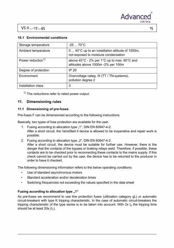
10.1 Environmental conditions
1) The reductions refer to rated power output.
11. Dimensioning rules
11.1 Dimensioning of pre-fuses
Pre-fuses F can be dimensioned according to the following instructions.
Basically, two types of fuse protection are available for the user. 1. Fusing according to allocation type „1“, DIN EN 60947-4-2.
After a short circuit, the VersiStart II device is allowed to be inoperative and repair work is possible.
2. Fusing according to allocation type „2“, DIN EN 60947-4-2. After a short circuit, the device must be suitable for further use. However, there is the danger that the contacts of the bypass or braking relays weld. Therefore, if possible, these contacts are to be checked prior to reconnecting these contacts to the mains supply. If this check cannot be carried out by the user, the device has to be returned to the producer in order to have it checked.
The following dimensioning information refers to the below operating conditions:• Use of standard asynchronous motors• Standard acceleration and/or deceleration times• Switching frequencies not exceeding the values specified in the data sheet
Fusing according to allocation type „1“As pre-fuses we recommend to use line protection fuses (utilization category gL) or automatic circuit-breakers with type K tripping characteristic. In the case of automatic circuit-breakers the tripping characteristic of the type series is to be taken into account. With 2x In the tripping time should be at least 20s (I1).
Storage temperature -25 ... 70°C
Ambient temperature 0 ... 45°C up to an installation altitude of 1000m, not exposed to moisture condensation
Power reduction1) above 45°C - 2% per 1°C up to max. 60°C and altitudes above 1000m -2% per 100m
Degree of protection IP 20
Environment Overvoltage categ. III (TT / TN-systems), pollution degree 2
Installation class 3

16 VS II ...-17 ... 45
The fuse values are to be determied by taking the conductor cross-sectional area of the wiring into account. Depending on the rated motor current, the maximally occurring starting current (normally up to the 5-fold rated device current) and the starting frequency, the wiring cross-sectional area is to be determined. Table 1 shows the values for numerous applications, i.e., with a 3-fold nominal current as mean starting current and a max. starting time of 10s. In the case of parameter values exceeding these values, it may be necessary to adapt the fuse value accor-dingly.
Note: Wiring cross-sectional area according to DIN VDE 0100-430, DIN EN 57100-430.
Table 1
Fusing according to allocation type „2“:The power semiconductors are to be protected by fuses of the utilization class gR (semiconductor protection fuses, high-speed fuses). However, since these fuses do not ensure line protection, it is necessary to use additionally line protection fuses (utilization category gL).To protect the semiconductors it is necessary to select gR-fuses featuring cutoff-I²t-values which are approx. 10-15% below the I²t-value of the power semiconductor (see technical data). In this connection, the fuse rating of the selected fuse should not be smaller than the starting current to be expected.
Note: Advanced control does not prescribe the use of semiconductor protection fuses. However, for some UL- or CSA-listed devices there are exceptions which are indicated in the relevant commissioning instructions.
Note 1 On the basis of the I²t-value of the power semiconductors, the starting time and possibly the max. starting current, the fuse supplier is able to select a suitable type. Due to the great variety of producers, sizes and types, AdvancedControl does not recommend any particular fuses.
Note 2 If the value of the fuse or the cutoff-I²t-value is selected too small, it may happen that the semiconductor fuse reacts during the starting phase or during deceleration.
Rated device current (techn. data)
Device type Fuse value in the case of allocation type 1
Starting frequencies Starts / h
17A VS II 400-17 25A 40
25A VS II 400-25 35/40A 30
32A VS II 400-32 50A 20
45A VS II 400-45 63A 20

VS II ...-17 ... 45 17
11.2 Determining the permissible starting frequency
The starting frequency depends on the:1. starting current or the heat loss across the power semiconductors.2. current carrying capacity and the temperature increase of the power semiconductors.3. heat sink’s capability of absorbing the heat loss and passing the temperature increase on
to the environment.
The following diagrams are to assist you in determining the maximum starting frequency per hour, i.e., on the basis of the given maximum starting current and for various starting times.Should the requested starting frequency not be reached, a different device series has to be chosen.
Example: In a drive, a 15 kW-motor is to be started. A maximum starting current of 120A has been measured. This approximately corresponds to the 4-fold nominal current. The device employed is a VS II 400-32. From the applicable chart it is now possible to read off a max. starting frequency per hour lying between 280 (starting time = 1s) and 28 (starting time = 10S).
VersiStart II 400-17
2xIe
2xIe
3xIe
3xIe
4xIe
4xIe
5xIe
5xIe
6xIe
6xIe
1
10
100
1000
1 10
Anlaufzeit/Ramp-up time (s)
Star
ts/h

18 VS II ...-17 ... 45
VersiStart II 400-25
2xIe
2xIe
3xIe
3xIe
4xIe
4xIe
5xIe
5xIe
6xIe
6xIe
1
10
100
1000
1 10
Anlaufzeit/Ramp-up time (s)
Star
ts/h
VersiStart II 400-32
2xIe
2xIe
3xIe
3xIe
4xIe
4xIe
5xIe
5xIe
6xIe
6xIe
1
10
100
1000
1 10
Anlaufzeit/Ramp-up time (s)
Star
ts/h

VS II ...-17 ... 45 19
These devices must be reseted by disconnect the auxiliary voltage.
VersiStart II 400-45
2xIe
2xIe
3xIe
3xIe
4xIe
4xIe
5xIe
5xIe
6xIe
6xIe1
10
100
1000
1 10
Anlaufzeit/Ramp-up time (s)
Star
ts/h

20 VS II ...-17 ... 45
12. Special unitsThe rated voltage of a device featuring special voltage is indicated on the rating plate. In the case of devices with voltages < 400V it must be ensured that the device rating and the motor rating are not identical. Of prime importance in this connection is the rated device current and the motor current according to rating plate.
12.1 Devices with rated voltage of 230V or 480V
It must be ensured that the mains voltage value indicated on the rating plate is connected to the terminals L1, L2, L3.Otherwise the devices are to be put into operation like standard devices.
12.2 Devices featuring a wide-voltage-range power section
In the case of wide-voltage-range-capable devices1 the voltage range for the power supply is 200V ... 480V. Besides, in order to operate the devices, it is necessary to connect an control supply voltage US of 24VDC ±10%/150mA to the terminals X1 (+24V) and X4 (ground).
Caution:
These devices must be reseted by disconnect the auxiliary voltage.
Otherwise the devices are to be put into operation like standard devices.
12.3 Devices featuring special voltage >= 500V
Devices >= 500V are equipped with power semiconductors featuring higher reverse voltages. These devices are to be connected and put into operation like devices having a wide-voltage-range power section.
12.4 Devices with motor-PTC input
In the case of these devices, it is possible to connect a motor-PTC for motor temperature monitoring. The sensor lines of the motor-PTC are to be connected to the terminals X3 and X4 ( ).If the motor temperature exceeds the switching threshold, the motor PTC triggers a fault. The soft starter switches the motor off and is interlocked in fault mode. The fault is signalized by the yellow LED repeatedly flashing two times and by an opening of the relay contact between the terminals X5 and X6. Let the motor cool down, identify the root cause and remove the cause of the intense heating up of the motor. By switching off the supply voltage, the soft starter can be reset from fault mode into operating mode.
1. with option „B“

VS II ...-17 ... 45 21
Attention!
To avoid EMI couplings into the electronics and they disturbances they involve, it is not allowed to use free, unshielded strands in the motor cable for connecting the temperature sensor to the soft starter. The temperature sensor should be connected with the soft starter by a separate, and preferably, shielded cable. The line ends are to be neatly terminated and unshielded lines must be kept as short as possible. The sensor cable is, as far as possible, to be laid separately from the power cables in separate cable ducts. If crossings of power cables and control cables are inevitable, they should be arranged at an angle of 90°.

22 VS II ...-17 ... 45
13. Installation guidelineThe devices are to be installed into a switchbox or switchgear cabinet according to point 2 and 4. It must be ensured that the switchbox/switchgear cabinet is capable of dissipating the occurring heat loss (see techn. data).
13.1 Connection
The device is to be installed according to the attached connection diagram. For other connections please consult Advanced Control.
13.1.1 Earthing
The electricalearthing provided ensures a low impedance connection between all metallic surfaces. Apart providing a degree of electrical safety and isolation, the earthing also has the beneficial effect that the flow of RF currents can be directed through the structure of the equipment rather than trough sensitive circuits, where it could be disruptive. It is for this reason that it is vitally important to provide separate earth conductors for each part of the installation all connected to a common star point.
13.1.2 Cabling
To avoid EMI couplings into the electronics and the disturbances they involve, it must be ensured that the control cables are laid separately in separate cable ducts and as far as possible away from the power cables. If control cables crossing power cables, they have to be laid at an angle of 90° (Figure 3).When connection shielded cables make sure that the unshielded cable ends are as short as possible. The large-surface shield bonding must not necessarily be located on the end of the shielding but may also be established in a suitable place - at a distance of some centimetres (Figure 4).
Figure 3 Figure 4
at least20cm
control cable
power cable
90°
vamish removedmounting plate
large-surfaceshield bonding
unshielded endsas short as possible
terminals

VS II ...-17 ... 45 23
Caution:
The protective conductor connection to the motor must no be laid in shielded motor cables, but is to be separately laid with an appropriate cross-sectional area. The individual earthing systems, power earth, protective earth, digital earth, and analog earth conductors should be laid separately by using a suitable star-point wiring.
Note: Further connection diagrams for special circuit arrangements are available on our homepage at www.advcontrol.eu
Note: Prior to putting the VersiStart II into operation the wiring is to be checked.

24 VS II ...-17 ... 45
13.2 General connection diagram
X2
M
3 ~
2T1
1L1 3L2
4T2
X1
5L3
6T3 +
PE L2L1 L3
X6X5
F
X4X3 X8X7
Start
Boost
Fault Devicebypassed
Control with10 ... 24VDC
RA1 RA2
VS II 400-17...45
PE
control supply U 24DVCat option "B"
If you want to further reduce the interference voltage onthe mains supply line during acceleration or deceleration(devices with low immunity to interference in closeproximity), three X-capacitors 0,15µF/400V and twosingle-phase line reactors 3mH have to be connected.
s
VS II ...-17 ... 45 25
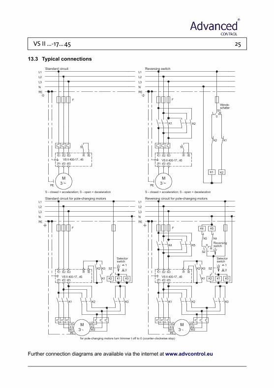
13.3 Typical connections
Further connection diagrams are available via the internet at www.advcontrol.eu
for pole-changing motors turn trimmer t off to 0 (counter-clockwise stop)
U2
X21L1 3L2 5L3 X1
4T22T1
PE
U1V1W1
M
3 ~
K1
6T3
L2
L3
N
PE
W2V2
K1 K2
K2
K1 K3
K3
K2 K3 S22
1
Selectorswitch
S - closed = acceleration; S - open = deceleration
Standard circuit for pole-changing motors
X2
~
M
3L2
4T2
VS II 400-17...45
L1
3PE
1L1
2T1
5L3
6T3
X1
S
Standard circuit
L2
L3
N
PE
L1
U2
X21L1 3L2 5L3 X1
4T22T1
PE
U1V1W1
M
3 ~
K1
6T3
L2
L3
N
PE
K4
W2V2
K1 K2
K2
K1 K3
K3
K4
Reversingswitch
K5
K2 K3 S2
K5 0L R
S2
K4 K5
2
1
Selectorswitch
Reversing circuit for pole-changing motorsL1
S - closed = acceleration; S - open = deceleration
X2
~
M
3L2
4T2
3PE
1L1
2T1
5L3
6T3
X1
S
Reversing switch
L2
L3
N
PE
L1
K1
K2
K1 K2
K1
L
K2
0R
S1
Wende-schalter
VS II 400-17...45
VS II 400-17...45 VS II 400-17...45
FF
F F

26 VS II ...-17 ... 45
13.4 Motor/Soft start in delta connection (only units with option „M“)
Further connection diagrams are available via the internet at www.advcontrol.eu
X2
~M
3L2
4T2VS II 400-17...45 M
3PE
1L1
2T1
5L3
6T3
X1
L2L3NPE
L1
K1
U2
U1 V 1 W1
W2V 2
F
Start
K1
F
X7 X8

VS II ...-17 ... 45 27
13.5 Wide-voltage-range connection
Further connection diagrams are available via the internet at www.advcontrol.eu
+X3
~M
3L2
4T2VersiStart II 400-17...45 B
3PE
1L1
2T1
5L3
6T3
X2
L2L3NPE
L1
X1
Star
t
X7X6X5 X8
X4
Control supplyU = 24VDC
Boos
t
RA1 RA2
F
s
ext. control inputU 10 ... 24VDCc
Fault Devicebypassed

28 VS II ...-17 ... 45
14. Dimensions
All dimensions indicated in mm.
15. Special unitsPlease see supplement.
Mounting dimensions a b c d e
VS II 400-17…32 125 158 53 45 173
VS II 400-45 125 158 53 52.5 178
On
Bypass
versi start II
12345678
0100%
0100%
0100%t
t
UStart
c
b
a
d
e
L1 L2 L3
T1 T2 T3

Advanced Systems Baltic OU Punane 73, 13619 Tallinn, Estonia advcontrol.eu
advcontrol.eu
Тел: +372 62 28 220 E-mail: [email protected]