assembly and maintainance instructions - · pdf file4 ausgabe 10/2003 1. description the...
TRANSCRIPT

Assembly and Maintainance InstructionsMechanical Sliding Caliper Disc Brake
Type PAN 19-1
1st Edition
720 001 024 37200010243
This publication is not subject to any update service.New versions are available in INFORM at www.wabco-auto.com
7200010203
� Copyright WABCO 2004
Vehicle Control SystemsAn American Standard Company
The right of amendment is reservedVersion 001/10.03(en)
Wabcodruck 720 001 024 3


31
Table of contents
Page
1. Description the Mechanical Sliding Caliper Disc Brake 4
1.1 Introduction 4
2. Service Instructions 5
2.1 Safety tips during repair 5
2.2 Checking Brake Function 5
2.2.1 Checking Adjuster Function 6
2.3 Checking Brake Pads 7
2.4 Checking Brake Disc 8
3. Renewing Brake Pads 8
4. Renewing Brake 16
5. Renewing Gaiters 18
5.1 Renewing Guide Pin Gaiters and Bushes 18
5.2 Renewing Adjuster Screw Gaiter 23
6. Renewing Brake Cylinder 25
Table 1: Spanner Widths [AF] and Tightening Torques [Nm] 26
Note:The Service Instruction focuses on trained specialists. Operations on the brake can only becarried out if the appropriate paragraphs have been read through and understood. The safetyinstructions according to paragrahph 2.1 are to be considered and to be followed.
These Service Instructions are copyright. All rights reserved.
This publication is not subject to any update service. You will find the latest versions in INFORM under www.wabco-auto.com when quoting the publications number 720 001 024 3
No part of this publication maybe reproduced, stored in a retrieval system, or transmitted inany form or by any means, electronic, photocopying, recordinf or otherwise withoutpermission in writing from WABCO.

4 Ausgabe 10/2003
1. Description the Mechanical Sliding Caliper Disc Brake1.1 Introduction
The brake PAN 19-1 is a new developed one-piston-brake, which is intended for use in commercialvehicles and trailers on front and rear axles for 19,5" or22,5" wheel rims as service, auxiliary and parking brake.It is actuated mechanically via a diaphragm brakecylinder or a spring brake cylinder. This is mounted tothe end cover of the brake caliper.
A very compact unit is achieved by the direct mountingof the brake cylinder onto the caliper. This enablesoptimal utilisation of the installation situations.
The complete disc brake including brake cylinderconsists of two assemblies:
� Brake caliper (1)
� Brake Carrier (2)
The radially open design of the brake caliper allows forsimple and quick changes of the brake pads.
Brake pads with a large wear volume are used in orderto prolong the pad replacement intervals with this brake.
The internal moving components are lubricated for lifeand all sealing components are maintainance freeunless damaged.
The disc brake is equipped with an electrical wearindicator / sensor (40).
Mechanical Sliding Caliper Disc BrakePAN 19-1
Fig. 1
1
2

5Ausgabe 10/2003
Mechanical Sliding Caliper Disc Brake PAN 19-1
2. Service Instructions
This instruction with the following pictures contains therequired steps and work sequences to replace theavailable repair kits. The spanner size and the tighteningtorques in the sequneces are listed in Table 1 (see page26). For lubrication use only the tube of grease supplied withthe brake repair kit.
2.1 Safety tips to be considered duringrepair
The flawless technical condition of the disc brake is mostimportant to ensure goog driving and safe brakingcharacteristics.
Observe brake pad and disc wear limits!Worn-out pads and discs reduce the brakeeffectiveness and cause brake failure!Danger of accidents! Burned, glazed or oilcontaminated brake pads must be replacedimmediately. Always replace brake pads on a per axlebasis!
During repairs on the brake the vehicle mustbe parked on a level surface be blocked toprevent to prevent rollaway. Only approvedand suitable fixtures are to be used for thelifting and blocking of the vehicle. Whileworking on the brake it must be ensured thatthe brake cannot be actuated inadvertently.Do not actuate the brake while the brakepads are removed. Danger of Bodily Injury!
Do not clean the brake with pressurised air orother high cleaning pressure apparatus.Danger of Bodily Injury!
Keep hands and fingers out of the inside ofthe caliper to avoid injury!
A second technican must assist duringremoval and installation of the brake. HeavyLoad - Danger of Bodily Injury!
During repairs outside of the vehicle, thebrake must be secured in a fixture, such as aheavy vise as high torque is required duringremoval and installation of the bolts. Dangerof Bodily Injury!
The brake caliper with clamping unit shall not beopened. Therefore the bolts holding the cover shall notbe loosened.
Only original and genuine WABCO Service Parts andapproved brake pads are to be used.
During repairs use only recommended tools. Do not usea power-driven socket or tools! Tighten nuts and boltsonly to specified torque limits.
With newly installed brake pads on the first 50 km noemergency stops should be made. Also avoid longbraking cycles and force brakings.
When wear of the cast brake parts such as cracks orheavy abrasion is noticied replace the entire brakeassembly according to the instructions.
Upon completion of repairs the vehicle's braking systemmust be tested on a roller dynamometer. If no rollerdynamometer is available a driving test with brakeapplications must be perfomed.
2.2 Checking Brake Function
Caution: Do not use a power-driven socket! Whileworking at the brake or moving of thebrake caliper handle the caliper only fromoutside to avoid injury!

6 Ausgabe 10/2003
2.2.1 Checking Adjuster FunctionGeneral Note: The turning directions and the torques for the hexagonon the adjuster nut are given in Table 1, Position I.
Work sequences:• Remove plug (12) for the adjuster from the caliper
(22) carefully.
Caution:On disassembly the proper tool position isagainst the plug 12 (left side in Fig. 2)!Do not place the tool between caliper and outer sideof the sealing ring otherwise there is a danger of thedamaging the inner sealing ( right side in Fig. 2)
• Using a SW8 ring spanner (Table 1, Position I) turnthe adjuster (22) hexagon approx. 1/2 turn in theclockwise direction.
Caution: Do not overload the adjuster hexagon! Do not usean open-ended spanner. With the ring spannermounted on the adjuster nut ensure that there issufficient such that it will not be prevented fromturning during the adjuster check.
• Actuate the brake about approx. 5 times (apprx. 1bar) The adjuster is functioning when the ringspanner (arrow) turns in the anti-clockwise with everybrake actuation.
Note: With increasing adjustment increments theangular movement of the ring spanner becomessmaller.
The adjuster is in order when the ring spanner rotates asdescribed above.
• Remove ring spanner.
• Refit plug (12) ensure that the plug is placedproperly.
Failures that might occur:The adjuster (22) respectively ring spanner (arrow)
a) does not turnb) turns only with the first actuationc) turns forward and backward with every actuation
then the adjuster is not ok.
Change the brake according to Section 4!
Mechanical Sliding Caliper Disc BrakePAN 19-1
1222
Fig. 2
Fig. 4
1222
Fig. 3
12

7Ausgabe 10/2003
Mechanical Sliding Caliper Disc Brake PAN 19-1
2.3 Checking Brake Pads
Note: the brake pad thickness is to be checked regularlydenpending on operating conditions duringmaintainance intervals and under applicable local lawsand regulations. Burned, glazed or oil contaminatedbrake pads must be replaced immediately.
Always replace brake pads on a per axle basis!
Work sequences:Caution: To avoid damage to the brake disc, the brake padsshould be replaced at the latest when the thinnestsection of the friction material is 2 mm.
The thickness of the residual friction material should notbe less than 2 mm.
A = residual friction material thickness 2 mm.
B = total friction material thickness 21 mm
At residual friction material thickness A < 2 mm renewbrake pads according to Section 3.
Measuring of WearThe average brake pad wear can be measured,depending on the access, at the close fit (longer guidepin at the brake disc entry) or at the clearence fit (shorterguide pin at the brake disc exit).
Therefore measure the thickness (X) of the flage of theaxle and the distance (Y) between the flange and theedge of the brake caliper of the particular close fit(arrows).
The maximum wear is reached or exceeded wtih thefollowing values.
shorter guide pinmaximum wear X+Y > 95 mm Change lining
Longer guide pinmaximum wear X+Y > 122 mm Change lining
Brake pads Friction material
Fig. 5
Fig. 6
XY

8 Ausgabe 10/2003
2.4 Checking brake disc
Work sequences:
• Remove brake pads according to section 3 andmeasure thickness disc over the rubbing faces.
C = total disc thickness - new 45 mmD = wear allowance limit 37 mm
the brake disc must be renewed.The renewal is recommended on a per axlebasis.
E = total pad thickness - new 30 mmF = pad backplate thickness 9 mmG = minimum residual friction material thickness 2 mmH = absolute minimum pad thickness 11 mm
the brake pads must be renewed.
Caution: Observe brake pad and disc wear limits!Worn-out pads and discs reduce thebrake effectiveness and cause brakefailure! Danger of accidents!
3. Renewing Brake PadsCaution: Do not use a power-driven socket! Whileworking at the brake or moving of thebrake caliper handle the caliper only fromoutside to avoid injury!
Working sequences for removal of pads:• Disconnect cable of the wear indicator 40 at the plug
(arrow).
• Remove hexagon bolt (39) with spanner SW 17(Table 1, position II) from pad hold-down hoop (38).
Mechanical Sliding Caliper Disc BrakePAN 19-1
Fig. 7
Fig. 8
39
40
38

9Ausgabe 10/2003
Mechanical Sliding Caliper Disc Brake PAN 19-1
• Pad hold-down hoop (38) has to be withdrawn fromthe caliper (1).
• Remove three hold-down springs (37) from the brakpads (35 and 36) and the spreader plate (19).
• Remove cable guide (40) and contacts from thebrake pads.
• Both cable clips (41) have to be removed of the brakecaliper.
• Remove plug (12) for the adjuster (22) of the caliper(1) carefully.
Caution: While disassemblying plug (12) pleasenote the instructions for fig. 2!
• De-adjust the brake by rotating the hexagon on theadjuster nut (22) with a ring spanner than release byapprox. 1/4 turn.
Note: The turning direction to de-adjust is to the right,that means clockwise.
Fig. 9
38
1
41
35, 37
37
19, 37
40
Fig. 10
36
12 22Fig. 11

10 Ausgabe 10/2003
Caution:When re-adjusting push back the spreader plate (19)by hand to ensure that the pin as torsion lock (Fig.17) for the adjusting screw does not slip out of itsgroove.Otherwise the danger exsists that the adjusterscrew will turn thereby damaging its gaiter!
• Slide the caliper (1) by hand towards the wheel sideand remove the brake pad (35).
• Slide the caliper (1) by hand towards the wheel sideand remove the brake pad (36) and the spreaderplate (19).
Caution: Do not actuate the brake while the brakepads are removed. Danger of BodilyInjury!
• Using a wire brush remove any corrosion from thespreader plate, brake pad slot and brake pads guidesurfaces.
Caution: Take care not to damage the dust caps (5, 10). Theguide surfaces must be free of grease!
Mechanical Sliding Caliper Disc BrakePAN 19-1
Fig. 12
35
19
Fig. 13
36
19
5 510
Fig. 14

11Ausgabe 10/2003
Mechanical Sliding Caliper Disc Brake PAN 19-1
Checking of the Dust Caps (Gaiters) and the BrakeCaliper Movement:
• Slide the caliper towards the side to allowexamination of the gaiters (5, 10), the guide pins (8,9) and the adjuster screw (21) for wear and damage.Renew all defect gaiters according to Section 5.1and 5.2
Caution: In case of a defective the gaiter (10) must bechecked if dirt or water has already entered ordamaged the inner parts of the brake or the gaiterseat in the caliper by corrosion. In case of doubt thebrake must be renewed according to Section 4. If thegaiter (10) is damaged while the brake is serviced,the gaiter must be renewed according to Section 5.2.
• Slide the caliper on the guide pins by hand over itstotal displacement and check for freedom ofmovement.If the movement is restricted renew the guidepins bushes and gaiters according to section 5.1
Caution:Do not squeeze the dust caps of the guide pinsagainst the torque plate!
Checking of the Adjuster Unit (Clamping Unit):• Prevent the adjuster screw from turning during the
test and while rotating by the adjuster hexagone g holding the pin (arrow).
Fig. 15
5, 85, 9
10, 21
Fig. 16
Fig. 17
12 Ausgabe 10/2003
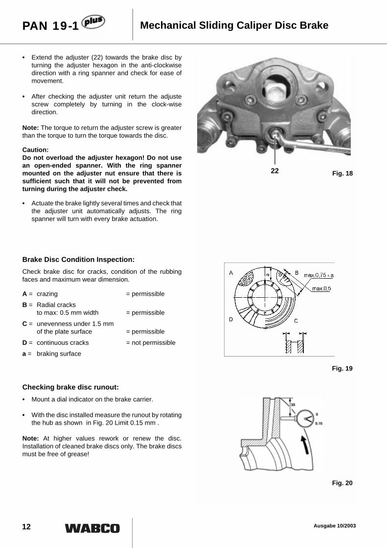
• Extend the adjuster (22) towards the brake disc byturning the adjuster hexagon in the anti-clockwisedirection with a ring spanner and check for ease ofmovement.
• After checking the adjuster unit return the adjustescrew completely by turning in the clock-wisedirection.
Note: The torque to return the adjuster screw is greaterthan the torque to turn the torque towards the disc.
Caution: Do not overload the adjuster hexagon! Do not usean open-ended spanner. With the ring spannermounted on the adjuster nut ensure that there issufficient such that it will not be prevented fromturning during the adjuster check.
• Actuate the brake lightly several times and check thatthe adjuster unit automatically adjusts. The ringspanner will turn with every brake actuation.
Brake Disc Condition Inspection:Check brake disc for cracks, condition of the rubbingfaces and maximum wear dimension.
A = crazing = permissibleB = Radial cracks
to max: 0.5 mm width = permissible
C = unevenness under 1.5 mm of the plate surface = permissible
D = continuous cracks = not permissiblea = braking surface
Checking brake disc runout:• Mount a dial indicator on the brake carrier.
• With the disc installed measure the runout by rotatingthe hub as shown in Fig. 20 Limit 0.15 mm .
Note: At higher values rework or renew the disc.Installation of cleaned brake discs only. The brake discsmust be free of grease!
Mechanical Sliding Caliper Disc BrakePAN 19-1
Fig. 1822
Fig. 19
Fig. 20

13Ausgabe 10/2003
Mechanical Sliding Caliper Disc Brake PAN 19-1
Working sequence for Pad Installation:
• Slide the caliper untile there is sufficient spacebetween the actuation side and the disc to insert thebrake pad.
• Insert spreader plate (19) in the brake carrier andengage with the adjuster screw (21).
Caution: The spreader plate must be located within the brakecarrier abutments and the pin in the adjuster screwmust be located in the slot of the spreader plate.Otherwise the function of the adjuster mechanism isnot ensured! The adjuster screw can be turned toobtain alignment. The gaiter may not be twisted!
• New brake pad (36) has to be inserted on theactuating side
• Slide the caliper toward the wheel until the brake pad(36) contacts the disc.
• New brake pad (35) has to be inserted on the wheelside.
• Using a 1 mm thick feeler gauge (arrow) insertedbetween the backing plate of the brake pad on thewheel side and the brak caliper, turn the hex nut (22)of the adjuster screw with a closed end wrench untilboth brake pads contact the brake disc.
Caution: Do not overload the adjuster hexagon (22)!
Note: The turning direction to adjust the break is to the left, thatmeans anti-clockwise. Do not fit pad hold-down hoopbefore adjusting air gap.
Fig. 21
Fig. 22
21
36
19
Fig. 23
22
35

14 Ausgabe 10/2003
• Fit new cable clips (41) to the brake caliper.
• Install new pre-assembled wear indicator and thecable guide (40) and insert sensor contact into thebrake pads.
Caution: The sensor contacts must be pointed in thedirection of the break disc and the contacts must beproperly seasted!
• Raise cable guide (40),
• Place three new hold down springs (37) under thecable guide and on top of the spreader plate and thebrake pads.
Caution: Route cables on the actuation side so that they donot rest on the brake pad (see cable position to theFig. 25).
• Then push cable guide against the hold-downsprings and position on brake caliper.
Mechanical Sliding Caliper Disc BrakePAN 19-1
41
40
41
40Fig. 24
Fig. 2537
Fig. 26
15Ausgabe 10/2003
Mechanical Sliding Caliper Disc Brake PAN 19-1
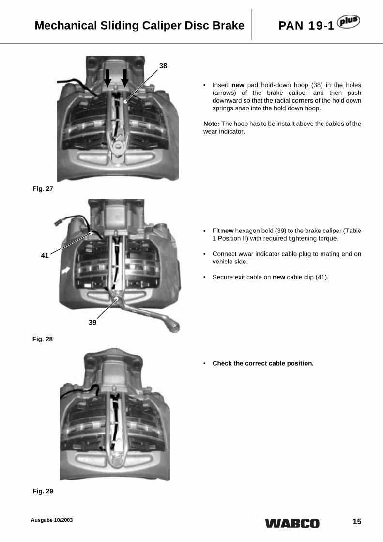
• Insert new pad hold-down hoop (38) in the holes(arrows) of the brake caliper and then pushdownward so that the radial corners of the hold downsprings snap into the hold down hoop.
Note: The hoop has to be installt above the cables of thewear indicator.
• Fit new hexagon bold (39) to the brake caliper (Table1 Position II) with required tightening torque.
• Connect wwar indicator cable plug to mating end onvehicle side.
• Secure exit cable on new cable clip (41).
• Check the correct cable position.
38
Fig. 27
39
41
Fig. 28
Fig. 29

16 Ausgabe 10/2003
• Fit new plug (12) to the opening in the brake caliper!Check and make sure the correct seat!
• Check that the hub rotates freely.
Caution: Upon completion test the brakes on the rollerdynamometer!
4. Renewing BrakeCaution: Do not use a power-driven socket! Whileworking at the brake or moving of thebrake caliper handle the caliper only fromoutside to avoid injury!
Note: The new brake is supplied as a pre-assembledunit and may be mounted to the vehicle's axle via thebrake carrier. Observe left (Illustration A) and right(Illustriation B) brake configurations. The removedbrake pads must be tested according to section 2.3 forwear. If the use of new brake pads is necesary therenewal is recommended on a per axle basis.
Work Sequences for Brake Removal:• Remove brake pads according to Section 3.
• Remove brake cylinder from brake caliper accordingto Section 6.
• Dismantle the caliper with the carrier from the acle(Table 1, Position III).
• Check brake disc according to Secction 2.4.
Mechanical Sliding Caliper Disc BrakePAN 19-1
12 Fig. 30
Fig. 31

17Ausgabe 10/2003
Mechanical Sliding Caliper Disc Brake PAN 19-1
Work Sequences for Installing Brake:
• Place the new brake with the brake carrier over thebrake disc and mount on the axle. Thighten hexagonbolts with spanner (Table 1, Position III).
Note: Special assembly instructions of the vehiclemanufacturer have to be noted.
• Remove the transport protection cap from thecylinder flange on the brake caliper.
• Refit brake pads and sprader plate according toSection 3.
• Refit the brake cylinder on the caliper according toSection 6.
Caution: With the brake cylinder inits installed position,ensure that the lower drainage hole facing theground is open! All other holes must be plugged!
Fig. 32
Fig. 33
Fig. 34

18 Ausgabe 10/2003
5. Renewing GaitersCaution: Do not use a power-driven socket! Whileworking at the brake or moving of thebrake caliper handle the caliper only fromoutside to avoid injury!
Note: When replacing all of the gaiters in the caliper, thework sequences 5.1 and 5.2 are to be combined. In thiscase work sequences need not to be repeated severaltimes.
Whenn replacing individual gaiters, follow thecorresponding work sequences of the seccions 5.1 and5.2.
5.1 Renewing Guide Pin Gaiters andBushes
Working Sequences for Removal:• Remove brake pads according to Section 3.
• Remove brake cylinder from brake caliper accordingto Section 6.
• Dismantle the caliper with the carrier from the axleaccording to Section 4.
• Dismantle brake caliper (1) from brake carrier (2) byremoving short and long caps (11, 11.1) from theguide pins (8, 9) in the caliper housing with a suitabletool, e.g. chisel.
Caution: Take care not to damage cover bores in housing.The proper tool position is against the cover.
Mechanical Sliding Caliper Disc BrakePAN 19-1
Fig. 35
Fig. 36
11, 11.1 8, 9
1
2
F

19Ausgabe 10/2003
Mechanical Sliding Caliper Disc Brake PAN 19-1
• Release the bolts (6, 7) with a male socket (Table 1,Position IV) and separate the caliper (1) from thecarrier (2).
Caution: Moving Brake Caliper: Danger of BodilyInjury!
• Clean the mating surfaces (collars) of the carrier (2).
• Withdraw the guide pins (8, 9) and remove thegaiters (5) from the caliper1.
• Place the caliper (1) on a firm base to push out thebushes (4), so that the caliper opening is facingupwards.
• Press the bushes (4) out of the caliper (1) using amandrel.
• Clean the bores in the caliper.
7
2
1
6
Fig. 37
15
8, 9
Fig. 381
4 4
F
F
Fig. 39
Fig. 40

20 Ausgabe 10/2003
Working sequence for Installation:• Press in two new bushes (4) for the loinger guide pin
(8).
• Firstly (A) fit the inner bush with the special fitting tool(L1) and secondly (B) the outer bush with the specialfitting tool (L2) by pressingin as far as the mandrelabutment. Use special fitting tools from WABCOcase no. 12 851 021.
• Grease the bushes and the space between them.
• Press in new bush (4) for the shorter guide pin (9).
• Fit the bush (C) with special fitting tool (L3) bypressing in as far as the mandrel abutment. Use special fitting tools from WABCO case no. 12 851 021.
• Grease the bush.
• Fit new green gaiters (5) in the gaiter seats (ringgroove/arrow) in the brake caliper (1).
Note: Clean gaiter seats before fitment. The sealingseats must be free of grease. It is possible to fit thegaiters by hand. Ensure that the gaiters are fittedevenla into the seats in the brake caliper!
Mechanical Sliding Caliper Disc BrakePAN 19-1
L1
F
A
L2
F
BFig. 41
L3
F
C Fig. 42
Fig. 43
1
5

21Ausgabe 10/2003
Mechanical Sliding Caliper Disc Brake PAN 19-1
• Grease the sliding surfaces of the guide pins (8, 9)and the inner lip of the gaiters (5).
• Insert the new guide pins from the cylinder side intothe caliper (1) , and
• push gaiter (5) against its guide pin seat (8, 9).
• Move guide pins backwards and forwards as shownin Figure 44 several times. Check for ease ofmovement.
Caution: The longer guide pin (8) is a close fit and is locatedat the brake disc leading side. The shorter guide pin(9) is a clearence fit and is located at the brake disctrailing side.
Remove all exess grease. The brake carrier end ofthe guide pins (arrow) and the mating surfaces ofthe carrier must be freee of grease!
Do not lose the metal-ring on gaiter 5 and check theproper seat (right side in Fig. 44)!
• Place the caliper (1) on the carrier (2) and insert theguide pins (8, 9) into the collars in the carrier.
• Insert new bolts (6) (long for close fit pin 8), (7) (shortfor claerence fit pin 9) into the guide pins in thebreake caliper (1).
• Screw bolts to the brake carrier (2) with spanner(Table 1, Position IV).
Caution: On assembly ensure that the gaiters (5) are notdamaged or twisted during tightening the bolts.
Firstly, tighten the bolt for the close fit longer pin (8),followed by the bolt for the clearance fit shorter pin(9).
Should during the maintenance work the guide pin(8, 9) fastening to the carrier (2) be loosened, thennew bolts (6, 7) must be used when reasssembling!
1
8, 9
5
8, 9
1
7
6
5 2
Fig. 44
Fig. 45

22 Ausgabe 10/2003
• Move brake caliper backwards and forwards onguide pins (8, 9) several times. Check for ease ofmovement.
Caution: Do not squeeze guide pins dust caps against brakecaliper!
• Lubricate the bores for the caps (11, 11.1) in thebrake caliper (1).
• Place new caps (11, 11.1) in the bores in the brakecaliper and press home with a suitable tool.
Note: Fit the long cap (11.1) on the longer guide pin (8).Take care to avoid damaging the covers.
• Mount brake over the brake disc on the axleaccording to Section 4.
Note: Special assembly instructions of the vehiclemanufacturer have to be noted.
• Install brake pads and set clearence. Carry outaccording to Section 3. and pay attention to Notes.
• Before refitting the brake cylinder clean the mountingflange on the caliper and grease the concave seat(arrow) in the brake lever.
• Refit the brake cylinder on the caliper according toSection 6.
Caution: With the brake cylinder inits installed position,ensure that the lower drainage hole facing theground is open! All other holes must be plugged!
Mechanical Sliding Caliper Disc BrakePAN 19-1
Fig. 46
9
8
1111.1
11
F F
Fig. 47
Fig. 48

23Ausgabe 10/2003
Mechanical Sliding Caliper Disc Brake PAN 19-1
5.2 Renewing Adjuster Screw Gaiter
Note: If the gaiter only is to be renewed it is notnecessary to dismantle the brake caliper and cylinder.
Working Sequences for Removal:
• Remove brake pads and spreader plate according toSection 3.
• Pull brake caliper to actuation / cylinder side by hand.
• Pull the gaiter (10) out the annular groove in theadjuster screw (21).
• Remove the gaiter from the seat in the brake caliperby means of a screwdriver.
• Check the adjuster screw thread.
Note: For the purpose refit the wheel side brake pad sothat the adjuster screw cannnot be screwed completelyout of the adjuster. After the thread check remove thebrake pad.
2110
21
Fig. 49
Fig. 50
Fig. 51

24 Ausgabe 10/2003
• Secure adjuster screw (21) against turning (arrowFig. 51) and screw out the adjuster screw c. 30 mmby turning the adjuster hexagon in the anti-clockwisedirection with a ring spanner.
• Examine the thread for corrosion and damage whilstscrewing out.
Caution: The gaiter (10) can be renewed, if definitely no dirt orwater has penetrated into the brake caliper, or if thegaiter has been directly damaged during servicingthe brake. In case of doubt the brake must bereplaced according to Section 4., if nternal parts arecorroded.
• After examination grease the thread and partly screwback the adjuster screw in clockwise sense.
Working sequence for Installation:• Clean the gaiter (10) seat (arrow) in the caliper.
• Push the new gaiter (10) over the adjuster screw.Centralise the fitting tool on the gaiter (10) and pressthe gaiter into the seat in the caliper (1).
• Fit gaiter (10) into ist seat in the adjuster screw (21).Lubricate gaiter lip to ease fitment.
Note: Ensure that the gaiter lip in the annular groove inthe adjuster screw sits free of folds!
• Install brake pads and set clearence. Carry outaccording to Section 3. and pay attention to Notes.
Mechanical Sliding Caliper Disc BrakePAN 19-1
21
101
Fig. 52
Fig. 53
Fig. 54
Fig. 55

25Ausgabe 10/2003
Mechanical Sliding Caliper Disc Brake PAN 19-1
6. Renewing Brake CylinderCaution: Do not use a power-driven socket! Whileworking at the brake or moving of thebrake caliper handle the caliper only fromoutside to avoid injury!
Note: Only use cylinders as specified by vehiclemanufacturer. The following work sequences onlyinform in principle about the assembly and disassemblyof the brake cylinder. Detailed assemnbly and checkinstructions have to be unsed according to the cylindertype and the instructions of the cylinder manufacturer.
Working Sequences for Removal:• Make sure that the brake hoses are pressureless.
• Disconnect air line to cylinder (according to cylindermanufacturar's data).
• Remove brake cylinder from caliper by releasingcylinder nuts (Table 1, Position V).
Working sequence for Installation:Caution: With the brake cylinder inits installed position,ensure that the lower drainage hole facing theground is open! All other holes must be plugged!
• Before refitting the brake cylinder clean the mountingflange on the caliper and grease the concave seat(arrow) in the brake lever.
• Fit brake cylnder and tighten nuts with spanner(Table 1, PositionV).
• Reconnect brake hose to brake cylinder (accordingto cylinder manufacture's data).
Note: The brake hose must not be twisted or lacatedsuch that it will rub against anything! The brake hose ofthe air suply is not allowed to have an influence on themoveability of the brake caliper.
• Test air connection for leaks (according to cylindermanufacturer's data).
• Carry out function and effectiveness tests (accordingto cylinder manufacturer's data).
Fig. 56
Fig. 57

26 Ausgabe 10/2003
Position Spanner Width[SW]
Hexagon Tightening Torque:[Nm]External Internal
I 8 X –
Turning direction of the hexagon:• Adjust, anti-clockwise (left) maximum 3
air gap decrease
• De-adjust, clockwise (right), maximum 12,air gap increase
Caution: Do not use a power-driven socket!
II 17 X – 30 + 15
III 24 X –290 ± 20 recommended
Please note the special assembly instructions of the vehicle manufacturer!
IV 14 –
310 ± 30Tightening order for guide pins:
1. Close fit pin (long internal hexagon bolt)2. Clearence fit pin (short internal hexagon bolt)
V 24 – 210 - 30
Mechanical Sliding Caliper Disc BrakePAN 19-1
Table 1: Tightening torques