assembly and operating instructions · all persons in whose area the oscillating machine and the...
TRANSCRIPT

FRIEDRICH Schwingtechnik GmbH TK-Assembly and operating instructions UE-R1-160309DA_GB - 1 -
Assembly and operating instructions (Translated original)
Unbalance exciter Issue 03.16

FRIEDRICH Schwingtechnik GmbH TK-Assembly and operating instructions UE-R1-160309DA_GB - 2 -
Copyright by FRIEDRICH Schwingtechnik GmbH These operating instructions are copyright protected. Any reproduction or publication in whole or in part shall require express written permission. We reserve the right to make alterations without prior notification. FRIEDRICH Schwingtechnik GmbH P.O Box 10 16 44 D-42760 Haan Germany Sales:
Tel. National
International 02129 3790-0
+49 2129 3790-0
e-mail [email protected]
Fax:
Fax National International
02129 3790-37 +49 2129 3790-37
Internet:
Homepage http://www.friedrich-schwingtechnik.de

FRIEDRICH Schwingtechnik GmbH TK-Assembly and operating instructions UE-R1-160309DA_GB - 3 -
Contents 1. Notes on using these technical instructions ........................................................................................ 4 1.1 Who needs to be familiar with these technical instructions ................................................................................................. 4 1.2 Points for special considerations .......................................................................................................................................... 4 1.3 Explanation of pictographs used .......................................................................................................................................... 5 2. General .................................................................................................................................................. 6 3. Correct use ............................................................................................................................................ 7 4. Safety notes ........................................................................................................................................... 7 5. Transport ............................................................................................................................................... 8 6. Assembly ............................................................................................................................................... 9 6.1 Unpacking and checking delivery contents ......................................................................................................................... 9 6.2 Installation guidelines .......................................................................................................................................................... 9 6.3 Assembling on location ....................................................................................................................................................... 10 6.4 Assembling propeller shaft and drive motor connection piece ............................................................................................. 12 6.4.1 Coupled unbalance exciters ............................................................................................................................................... 12 6.5 Assembling the protective boxes .......................................................................................................................................... 14 6.6 Drive ..................................................................................................................................................................................... 15 6.7 Electrical connection ............................................................................................................................................................ 16 7. Testing guidelines ................................................................................................................................. 16 8. Storage and internal preservation ...................................................................................................... 17 9. Alteration of swing ............................................................................................................................... 17 10. Removing and installing additional weights .................................................................................... 20 10.1 Removing additional weights ............................................................................................................................................ 20 10.2 Installing additional weights .............................................................................................................................................. 21 11. Dimensions .......................................................................................................................................... 22 12. Technical data .................................................................................................................................... 23 13. Lubrication instructions .................................................................................................................... 23 13.1 Propeller shaft .................................................................................................................................................................... 24 14. Oil change intervals ........................................................................................................................... 24 14.1 Ventilation plug ................................................................................................................................................................. 24 15. Selection of used gear oils .................................................................................................................. 26 16. Oil level charts .............................................................................................................................................................. 27 16.1 How to understand the following angle specifications ....................................................................................................... 27 17. Spare parts and repairs, maintenance intervals ............................................................................................. 33 17.1 Spare parts ......................................................................................................................................................................... 33 17.2 Repairs .............................................................................................................................................................................. 33 17.3 Maintenance ........................................................................................................................................................................ 34 18. Warranty ....................................................................................................................................................................... 34 19. Declaration of incorporation ................................................................................................................................. 35
FRIEDRICH Schwingtechnik GmbH TK-Assembly and operating instructions UE-R1-160309DA_GB - 4 -
1. Notes on using these technical instructions
Please read the following pages in order to improve your understanding and utilization of these technical instructions. Always observe the following rules: These technical instructions must be read prior to use, assembly or taking into operation. General and local health and safety regulations must also be observed.
1.1 Who needs to be familiar with these technical instructions
All persons in whose area the oscillating machine and the unbalance exciter are set up must be familiar with these technical instructions.
Users must also be conversant with these operating instructions.
The electrician must be aware of the specifications on electrical instructions.
Service personnel must know the maintenance and repair instructions.
The following generally applies: Any person working on the unbalance exciter must be familiar with the contents of these technical instructions. Personnel must be qualified and given proper instructions. The operator is obliged to instruct his personnel accordingly.
1.2 Points for special considerations
Please ensure that these technical instructions ...
may generally not be separated or altered. Only FRIEDRICH Schwingtechnik GmbH may amend the instructions.
must be maintained complete in vicinity of the oscillating machine; missing pages or complete technical instructions can be requested from FRIEDRICH Schwingtechnik at any time.
must be available at all times to personnel operating the unbalance exciter/oscillating machine.
must be read and understood by service personnel prior to commencing maintenance or repair work on the unbalance exciter.
conforms to the unbalance exciter`s technical specification level at the time of delivery; subsequent amendments must be sufficiently documented and kept with the technical instructions. This also applies to all other copies of the technical instructions issued by us with the ubalance exciter.
is not, and may not amend part of an earlier or existing statement, agreement or legal relation. All obligations on the part of FRIEDRICH Schwingtechnik towards the customer are contained in the purchase agreement also containing the complete and solely valid guarantee rules. These contractual guarantee conditions are neither complemented nor limited by the technical instructions.
FRIEDRICH Schwingtechnik GmbH TK-Assembly and operating instructions UE-R1-160309DA_GB - 5 -
1.3 Explanation of pictographs used The following pictographs are used to facilitate work on these technical instructions and to
help you find what you are looking for. In principle, you should inform other users of the oscillating device as to all warnings.
i
Information This involves basic information and recommendations from FRIEDRICH Schwingtechnik. The following paragraph is to promote understanding or make your work easier. This paragraph does not have to be read. Failing to consider this will not result in direct danger or adverse affects.
Tests and checks Notes on the necessity of regular checks on oil levels and bolt fittings. Failure to observe this sign may lead to danger or damage.
Avoiding material damage Refers to increased danger of damage to the unbalance exciter, e.g. due to the use of incorrect tools, wrong type of oil, contaminated parts in contact with driving components, incorrect assembly sequence or inadequate transport. The opposite paragraph must be read and understood. Failure to observe this sign may lead to danger or damage.
Special tools This refers to the requirement to use special tools.
Please read This refers to standards and documents that must be read and understood.
General warning This pictograph gives a general warning. This refers to dangers, possible malfunctions, incorrect use or other things concerning work safety. The opposite paragraph must be read and understood. Failure to observe this sign may lead to danger or damage.
Warning of danger of injury This pictograph warns of a possible danger of injury. This refers to dangers, incorrect use or other things regarding work safety. This point requires careful attention and special measures must be taken. The opposite paragraph must be read and understood. Failure to observe this sign may lead to danger or damage.
Warning of high voltage This pictograph warns of electrical currents and resulting dangers. Appropriate measures must be taken against this. The opposite paragraph must be read and understood. Failure to observe this sign may lead to danger or damage.

FRIEDRICH Schwingtechnik GmbH TK-Assembly and operating instructions UE-R1-160309DA_GB - 6 -
Warning when transporting This pictograph warns of increased dangers that may occur when transporting the unbalance exciter. The opposite paragraph must be read and understood. Failure to observe this sign may lead to danger or damage .
Important advice This pictograph indicates an important recommendation or explanation. The opposite paragraph must be read and understood. Failure to observe this will not lead to immediate danger but can affect the machine`s operation.
2. General FRIEDRICH unbalance exciter machines are designed for operation in the interior of
oscillating machines, sieving machines or other vibration equipments with particularly high payloads and/or very high transport performance. The unbalance exciter machines consist of a robust cast iron housing with two shafts connected by gearwheels housed in generously proportioned special roller bearings with increased carrying force and bearing play. Lubrication of the bearings and gearwheels is carried out by a combination of immersion in oil and oil mist lubrication. Centrifugal weights are fitted on the end of each shaft. Up to 12 additional weights of steel or lead can be added to these depending on the use and required conveyor capability. The centrifugal weights linked by force synchronization are set into operation in opposing directions by an external standard drive motor via a propeller shaft. The propeller shaft is linked via a connection piece with a centrifugal weight from the long shaft. In contrast to unbalanced motors, unbalance exciter machines do not experience transverse vibrations when starting up or coasting due to asynchronous running. There is the possibility of deploying speed-adjustable drive motors when using FRIEDRICH unbalance exciter machines in a regulated vibration equipment. Pole changing motors and motors with electric speed adjustment can be used or a variable speed gear inserted between the unbalance exciter and the standard revolution engine. As rotary motors, all commercially normal motors of 50 Hz and 60 Hz may be used at the stated voltages. Pay attention not to exceed the highest permissible revolutions (see chapter 12. Technical data). All FRIEDRICH unbalance exciters are put through an internal test run in our factory prior to delivery.

FRIEDRICH Schwingtechnik GmbH TK-Assembly and operating instructions UE-R1-160309DA_GB - 7 -
Each FRIEDRICH Schwingtechnik unbalance exciter is fitted with the following type plate:
Fill oil before use and take note of oil change intervall! See operating instructions!
Vor Inbetriebnahme Öl einfüllen und Ölwechselintervalle einhalten! Betriebsanleitung beachten!
KWMotor
kNCentri. F.:
Fliehkraft:kgcm
Work. Mom.:
Arbeitsmom.:
Nr.:Type:
Postfach 10 16 44D-42760 Haanwww.friedrich-schwingtechnik.de
SCHWINGTECHNIK GmbH
FRIEDRICH
Unwucht-Erreger Unbalance Exciter
n max min -1
3. Correct use
The unbalance exciter is designed exclusively to drive an oscillating machine. Dimensioning of the oscillating equipment must correspond to the parameters of the unbalance exciter. The operation of the unbalance exciters is only permitted if the shafts are in a horizontal position. Any other or extended use is deemed inappropriate. No claim may be made against FRIEDRICH Schwingtechnik for damage resulting from this. Correct use also entails observing the operating instructions and in particular the inspection and maintenance instructions.
4. Safety notes
The unbalance exciter may only be taken into use if it has been correctly installed with the respective machine and all protective devices. All maintenance and adjustment work on the unbalance exciter may in principle to be carried out with the machine at a standstill. Steps must be taken to ensure the unbalance exciter cannot be turned on by accident or by unauthorized personnel prior to starting this work.
Important: When using and working with the unbalance exciter, its centrifugal weights may turn over unexpectedly. There is a danger of knocking or pressing.

FRIEDRICH Schwingtechnik GmbH TK-Assembly and operating instructions UE-R1-160309DA_GB - 8 -
5. Transport
In order to avoid danger to persons and damage to the unbalance exciter, the appliance should be transported with the necessary care. As well as the following points, general and local health and safety rules must be observed.
The following is of special importance:
When transporting out of Europe, the centrifugal weights must be secured or dismounted, otherwise the bearings may be damaged because of mechanical shocks.
The correct use of transport and lifting devices must be ensured.
When transporting unbalance exciters on pallets, make sure they cannot tip over.
Only DIN 580 ring bolts must be used for installing the unbalance exciter. Ropes, shackles, etc. may only be fitted to these ring bolts.
Lifting gear must be approved, undamaged and suitable for transport.
No additional weight may be fitted to the exciter as the ring bolts are only designed for the exciter`s own weight.
For safety reasons, devices for lifting the unbalance exciter must have double the lifting capacity of weight of the unbalance exciter.
The unbalance exciter may only be placed on its footing.
All transport damage must be reported to the manufacturer. Special care must be taken to ensure bearing surfaces and protective covers are undamaged.
It is not allowed to use protective covers, shafts or centrifugal weights for suspension of the unbalance exciter. Heavy knocks or falls will damage the bearings in the exciter and reduce the exciter`s life span. The centrifugal weights and the shafts may not come into contact with the lifting device. Do not use damaged exciters.
Table 1: Capacity of lifting devices
Type Permitted capacity of lifting devices Ring bolt [kg] DIN 580
UE 5,3-6 ( F ) 316 M 16 UE 6-6 ( F ) 324 M 16 UE 8-6 ( F ) 494 M 16 UE 10-6 ( F ) 508 M 16 UE 16-6 ( F ) 682 M 16 UE 24-8 ( F ) 778 M 16 UE 12-4 ( F ) 720 M 20 UE 17-6 ( F ) 796 M 20 UE 20-6 ( F ) 828 M 20 UE 30-6 ( F ) 1126 M 20 UEV 30-6 F 962 M 20 UEV 36-6 F 992 M 20 UEV 40-8 F 1242 M 20 UEV 45-8 F 1090 M 20 UE 50-6 ( F ) 1640 M 24 UE 58-6 ( F ) 1700 M 24
UE 67-8 F 1988 M 24 UE 80-8 F 1988 M 24
UE 65-6 ( F ) 1794 M 24 UE 88-6 F 2254 M 30
UE 125-8 F 2572 M 30

FRIEDRICH Schwingtechnik GmbH TK-Assembly and operating instructions UE-R1-160309DA_GB - 9 -
6. Assembly
The unbalance exciters are delivered ready for installation but without oil filling. When installing, the following must be observed :
Check the delivery for completeness in accordance with chapter 6.1 - "Unpacking and checking the delivery contents".
Transport the unbalance exciter in accordance with chapter 5 "Transport" to the installation location.
Ensure the dimensional accuracy and suitability of the installation location in accordance with chapter 6.2 - "Installation guidelines".
Carry out the fitting onto the oscillating machine in accordance with chapter 6.3 - "Assembly on location".
Adjust the centrifugal weights or the working torque in accordance with chapter 8.
The operation of unbalance exciters is only permitted if the shafts are in a horizontal position.
Important: Carefully remove all paint, grease and oil from bearing surfaces of the unbalance exciter and surfaces onto which the oscillating machine is to be fitted prior to installation.
In principle, when installing unbalance exciters, local and national health and safety rules must be observed.
Important: When using and working with the unbalance exciter, its centrifugal weights may turn over unexpectedly. There is a danger of knocking or pressing.
6.1 Unpacking and checking delivery contents
Unpack the unbalance exciter and check the delivery contents against the delivery note.
Dispose of the packaging material in accordance with respective disposal conditions.
6.2 Installation guidelines
Requirements of the installation location:
The terminal to which the unbalance exciter is fitted must be:
level
vibration free
free of paint, rust, grease and oil
flat

FRIEDRICH Schwingtechnik GmbH TK-Assembly and operating instructions UE-R1-160309DA_GB - 10 -
6.3 Assembling on location
The unbalance exciters are installed as follows:
Assembly of the unbalance exciter requires a level, vibration-free drive bracket. This base must be mechanically processed in order to maintain a perfect bearing surface.
The unbalance exciter machines are secured with DIN 931 or DIN 933 - 8.8 hexagon bolts and DIN 982 or 985 - 8 self-locking hexagon bolts. It is not allowed to use neither split lock washers, serrated lock washers nor something like this. If washers are used, they must be high-strength washers, e.g. HV-washers according to DIN6916 are suitable.
All the fastening elements can be used only one time.
Fastening screws require a certain minimum grip of bolt in order to achieve preliminary tension. Minimum grip of bolt must be triple of the nominal diameter.
The required length of bolt and projection is calculated according to DIN 13. Bolt end projection v = length of nut + 3 x thread pitch P
The hexagon bolts with clamping part should in principle be on the stand side of the unbalance exciter.
The hexagon bolts with clamping part should be tightened using a torque key in accordance with table 2 unless instructions from the vibration machine manufacturer state otherwise. In any case however, instructions from the manufacturer must be observed. If in any doubt, please contact the manufacturer or FRIEDRICH Schwingtechnik.
Table 2: Fastening screws for fastening the UEs on the traverse
Type
Bolts 8.8
Nuts 8
Number
Torque [Nm]
UE 5,3-6 ( F ) M 20 M 20 6 410 UE 6-6 ( F ) M 20 M 20 6 410 UE 8-6 ( F ) M 20 M 20 6 410
UE 10-6 ( F ) M 20 M 20 6 410 UE 16-6 ( F ) M 24 M 24 6 710 UE 24-8 ( F ) M 24 M 24 6 710 UE 12-4 ( F ) M 24 M 24 8 710 UE 17-6 ( F ) M 24 M 24 8 710 UE 20-6 ( F ) M 24 M 24 8 710 UE 30-6 ( F ) M 24 M 24 8 710 UEV 30-6 F M 24 M 24 8 710 UEV 36-6 F M 24 M 24 8 710 UEV 40-8 F M 24 M 24 8 710 UEV 45-8 F M 24 M 24 8 710 UE 50-6 ( F ) M 36 M 36 8 2530
UE 58-6 F M 36 M 36 8 2530 UE 67-8 F M 36 M 36 8 2530 UE 80-8 F M 36 M 36 8 2530
UE 65-6 ( F ) M 36 M 36 8 2530 UE 88-6 F M 36 M 36 8 2530
UE 125-8 F M 36 M 36 8 2530

FRIEDRICH Schwingtechnik GmbH TK-Assembly and operating instructions UE-R1-160309DA_GB - 11 -
Table 2a: Fastening screws, centrifugal weights
Type
Bolt 8.8
Nut 8
Torque [ Nm ]
UE 5,3-6 ( F ) M 16 M 16 210 UE 6-6 ( F ) M 16 M 16 210 UE 8-6 ( F ) M 20 M 20 410
UE 10-6 ( F ) M 20 M 20 410 UE 16-6 ( F ) M 20 M 20 410 UE 24-8 ( F ) M 20 M 20 410 UE 12-4 ( F ) M 20 M 20 410 UE 17-6 ( F ) M 20 M 20 410 UE 20-6 ( F ) M 20 M 20 410 UE 30-6 ( F ) M 20 M 20 410 UEV 30-6 F M 20 M 20 410 UEV 36-6 F M 20 M 20 410 UEV 40-8 F M 20 M 20 410 UEV 45-8 F M 24 M 24 710 UE 50-6 ( F ) M 24 M 24 710
UE 58-6 F M 24 M 24 710 UE 67-8 F M 24 M 24 710 UE 80-8 F M 24 M 24 710
UE 65-6 ( F ) M 24 M 24 710 UE 88-6 F M 24 M 24 710 UE 125-8 F M 24 M 24 710
If the use of a torque key on the screws is not possible because of space restrictions, suitable steps must be taken to achieve the necessary torque. Hydraulic screwdrivers must be used if in doubt (e.g. PLARAD)
The bolts` torque must first be checked after 40 operating hours. Further checks must be carried out every 1000 hours.
The unbalance exciter must be filled up with the necessary amount of oil in accordance with chapter 16 - "Oil level chart" and as per the installation position.
The unbalance exciters are not supplied with oil!
The ventilation plug must always be situated on the uppermost place of the unbalance exciter.
Important: if improper bolts, nuts and torques are used, the unbalance exciter may unfasten and cause huge damages. Possible danger for life!
Important: Note that most malfunctions and breakdowns occur due to incorrect or loose bolt fittings!

FRIEDRICH Schwingtechnik GmbH TK-Assembly and operating instructions UE-R1-160309DA_GB - 12 -
6.4 Assembling propeller shaft and drive motor connection piece
The propeller shaft and the connection piece are fitted between the unbalance exciter and the drive motor. FRIEDRICH Schwingtechnik does not deliver the propeller shaft and the connection piece to the drive motor as standard.
FRIEDRICH Schwingtechnik recommendation We strongly recommend the use of a protective box for the propeller shaft to prevent physical injury.
6.4.1 Coupled unbalance exciters
If two unbalance exciters are coupled together, following notes must be respected.
Unbalances of both exciters must be provided with the same additional weights. Be sure the unbalances of both exciters are exactly in the same position after mounting the propeller shaft. There are marks on the connection piece. The marks must be situated under the shaft.
The drive motor and the propeller shaft must be adequately dimensioned. Contact us in case of doubt.

FRIEDRICH Schwingtechnik GmbH TK-Assembly and operating instructions UE-R1-160309DA_GB - 13 -
Table 3: Connection piece on the unbalance exciter side
Type db [mm]
d [mm]
da [mm]
di [mm]
t [mm]
UE 5,3-6 (F) UE 6-6 (F)
BF 01 6 c12 Ø 62 6xM6x30-10.9
75 42h6 1,5
UE 8-6 (F) UE 10-6 (F)
BF 02 8 c 12 Ø 84 6xM8x30-10.9
100 57h6 2,0
UE 16-6 UE 16-6 F
BF 03 BF 04
10 c12 Ø 101,5 8xM10x40-10.9
120 75h6 2,0
UE 24-8 UE 24-8 F
BF 05 BF 04
10 c12 Ø 101,5 8xM10x40-10.9
120 75h6 2,0
UE 12-4 (F) UE 17-6 (F) UE 20-6 (F)
BF 06 10 c12 Ø 101,5 8xM10x40-10.9
120 75h6 2,0
UEV 30-6 F UEV 36-6 F UEV 40-8 F UEV 45-8 F
BF 07 10 c12 Ø 101,5 8xM10x40-10.9
120 75h6 2,0
UE 30-6 UE 30-6 F
BF 08 BF 09
12 c 12 Ø 130 8xM12x50-10.9
150 90h6 2,0
UE 40-8 BF 10 12 c 12 Ø 130 8xM12x50-10.9
150 90h6 2,0
UE 50-6 BF 11 12 c 12 Ø 130 8xM12x50-10.9
150 90h6 2,0
UE 50-6 F UE 58-6 F UE 67-8 F UE 80-8 F
UE 65-6 (F)
BF 12 12 c 12 Ø 130 8xM12x50-10.9
150 90h6 2,0
UE 88-6 F UE 125-8 F
BF 13 12 c 12 Ø 130 8xM12x50-10.9
150 90h6 2,0
di
db
dad
45°
t
FRIEDRICH Schwingtechnik GmbH TK-Assembly and operating instructions UE-R1-160309DA_GB - 14 -
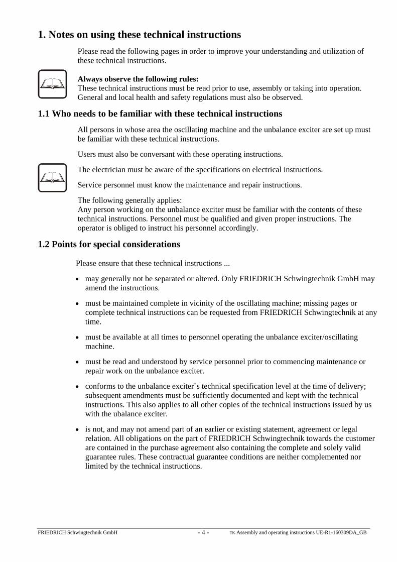
Table 4: Propeller shaft for connection of a single unbalance exciter Type Propeller shaft Fitting length b
[mm] Flange (DIN) Weight
[kg] UE 5,3-6 ( F ) UE 6-6( F )
GF 1 short GF 1
323 - 340 335 - 352
Ø 62 6xM6x30-10.9
MA = 14Nm 3
UE 8-6( F ) UE 10-6( F )
GF 5 short GF 5
365 - 380 435 - 500
Ø 84 6xM8x30-10.9
MA = 35Nm 5,7
UE 16-6( F ) UE 24-8( F ) UE 12-4( F ) UE 17-6( F ) UE 20-6( F ) UEV 30-6 F UEV 36-6 F UEV 40-8 F UEV 45-8 F
GF 2 short GF 2
430 - 470 470 - 530
Ø 101,5 8xM10x40-10.9
MA = 69Nm 8,4
UE 30-6( F ) UE 40-8
UE 50-6( F ) UE 67-8 F UE 80-8 F
UE 65-6( F ) UE 88-6 F UE 125-8 F
GF 3 short GF 3
525 - 570 585 - 650
Ø 130 8xM12x50-10.9
MA = 120Nm 14,2
List of standard FRIEDRICH propeller shafts. Other fitting lengths by request.
6.5 Assembling the protective boxes The protective boxes must be assembled prior to taking the unbalance exciter into use.
The fitting locations on the unbalance exciter and the protective boxes must be cleaned prior to assembly. The following sequence must be observed on installation: Both main segments are fitted with the lower closing sheets first.
The four plates are then placed over the slots. Make sure that a shorter plate is fitted to the side on which the connecting flange is mounted. This should be mentioned when ordering coupled unbalance exciters or a shorter plate ordered separately. Operation, including test runs are not permitted without fully mounted protective box and will release FRIEDRICH Schwingtechnik from any liability.
FRIEDRICH Schwingtechnik GmbH TK-Assembly and operating instructions UE-R1-160309DA_GB - 15 -
The cover of the propeller shaft must be assembled. This is not supplied with the protective box.
Important: The protective box must be completely assembled to be enough rigid. Otherwise, damage to the protective box cannot be excluded. The distance between the protective box and the fixed parts must be a minimum of 30mm. Please pay careful attention to this, especially in cases where the protective box is damaged (dents).
All bolts must be assembled without gaps and tightened up using a torque screw. The values for this are to be taken from table.
The bolts` torque must first be checked after 40 operating hours. Further checks must be carried out every 1000 hours.
Use only original parts provided by FRIEDRICH Schwingtechnik, otherwise mechanical and physical injury may occur.
Table 5: Fastening torque for bolts on the protective box
Bolt Fastening torque M 8 22 Nm M 12 80 Nm M 16 210 Nm
The unbalance exciter may not be taken into use without a completely assembled protective box. This also applies to test runs. The protective box protects against malfunction of the unbalance exciter as well as from rotating parts. Operation without the protective box will release FRIEDRICH Schwingtechnik from any liability.
6.6 Drive
FRIEDRICH Schwingtechnik does not include the drive motor in the delivery.
Both electrical motors and hydraulic motors can be used. The hydraulic motors must provide slow start, The motors can be connected with the unbalance exciter via a propeller shaft or a V-belt.
Note the following on the design of the unbalance exciter drive motor for the oscillating machine provided:
Please see chapter 12 - "Technical data" for the electric drive motor required. The fastening torque in the range 0-300 min-1 must be 2.5 times the nominal torque.
Please see chapter 12 - "Technical data" or the type plate for the highest permitted range.
Important:
The minimum range nmin may only fall short of 500 min-1 with written permission from FRIEDRICH Schwingtechnik.
The maximum range nmax in accordance with chapter 11 may only be exceeded with written permission from FRIEDRICH Schwingtechnik.
Failure to observe this may result in material or physical damage.
The falling short or exceeding of permissible ranges without prior written permission will release FRIEDRICH Schwingtechnik from any liability.

FRIEDRICH Schwingtechnik GmbH TK-Assembly and operating instructions UE-R1-160309DA_GB - 16 -
After switching off the drive motor, the exciter goes through the machine's frequency range and outlet vibration occur. Thi will lead to a slowing down of the transported material or vibrating of the oscillating machine. These undesired outlet vibrations can be avoided to a large extent by slowing down the motor whereby the brake may be operated at will. FRIEDRICH Schwingtechnik recommends braking via a DC brake.
The braking torque must not be greater than the motor's starting torque.
The unbalance exciter may only be started up if the oscillating machine is at a complete standstill.
6.7 Electrical connection
Electrical connection of the unbalance exciter drive motor may only be carried out by authorized specialist personnel according to the regulations and standards applying at the installation location. On the ground of safety reasons an emergency circuit breaker must be used. Important: Earth the drive motor according to the relevant protective regulations.
7. Testing guidelines
Important: Oscillating machines may in principle only be switched on at a standstill to avoid vibrations in the resonance range.
Check the following points before commencing the test run:
Free movability of all vibrating parts.
Proper oil and grease filling for the driving components according to details in chapter 15 - "Selection of available gear oils" and chapter 13 and 14 - "Oil level chart".
Installation location of the unbalance exciter within permissible environmental temperatures of -40°C and +50°C.
The test run may only be started from a local control station so intervention is possible at any time in the event of physical or material danger. An acoustic and if necessary, a visual signal of sufficient length must be given before starting the unbalance exciter.
The unbalance exciter should initially run one to two hours unloaded. The machine can be taken into use under load after checking the bolts for secure seating. Ensure the maximum operating temperature of +80°C is not exceeded.
The unbalance exciter may not be taken into use without a completely assembled protective box. This also applies to test runs. The protective box protects against malfunction of the unbalance exciter as well as from rotating parts. Operation without the protective box will release FRIEDRICH Schwingtechnik from any liability.

FRIEDRICH Schwingtechnik GmbH TK-Assembly and operating instructions UE-R1-160309DA_GB - 17 -
8. Storage and internal preservation
After successful finishing of the test run performed on our testing stand, all the unbalance exciters are given preservation for at least 12 months. It is intended to store the exciters inside closed dry stores under normal environmental conditions. In case of aggressive, moist environmental conditions, e.g. in tropics, storage life is reduced to 6 months. In order to prevent damage in storage, unbalance exciters should be stored without the centrifugal weights. When using an unbalance exciter after long time of inactivity, it is not necessary to wash it out. It must be filled with oil according to tables 8.1– 8.4. Free movement of the shafts must be checked by hand. If the shafts are not free to move, we recommend to let the unbalance exciter dismantle and clean at the producer. If an unbalance exciter should be stored also after expiration of the storage life, you must keep to the following way. Fill up the unbalance exciter with oil and rotate the shafts by hand. After that, get the oil out again. If vapour proof packaging is used, it is absolutely essential that as much of the solvent as possible be evaporated from the interior. It is advisable not to seal available ventilation devices for transport - including sea transport - and subsequent storage. Packaging must be agreed with the supplier or the packaging company as regards destination and storage time.
9. Alteration of swing The unbalance exciter machines have two gearwheel force-synchronized shafts fitted with
unbalances. The circulating masses produce a circulating radial power F of the same frequency on both shafts. An alternating force of value Fres = F1 + F2 in the direction of the exciter stand is produced due to the inverse synchronous circulation of the imbalances. An important characteristic for the selection of unbalance exciters is the so-called "static torque". The static torque of unbalance exciters is defined as the weight of all unbalances multiplied by the radius of the centre of gravity. FRIEDRICH Schwingtechnik uses working torque instead of static torque. This is calculated by doubling the static torque. Working torque is normally expressed in [kgcm].

FRIEDRICH Schwingtechnik GmbH TK-Assembly and operating instructions UE-R1-160309DA_GB - 18 -
Fig. 1
The amplitude of oscillation of vibrating movement of the vibration device is calculated from the unbalenced exciter’s working torque and the weight of the vibrating parts on the vibration device as follows :
Working torque [kgcm] Swing = —————————————— = 2 * Amplitude [cm] Mass of oscillating parts [kg]
The oscillation device’s static and thus working torque can be altered in stages with the machine at standstill by installing and removing additional weights. Please see table 6 - "Working torque according to the additional weights" for the grading of the additional weights. By altering the swing, there is a possibility of altering the throughput of the vibration device.
Chapter 10 - "Removal and installation of additional weights" gives information on changing additional weights.
Table 6 shows the amount of working torque depending on the number and position of additional weights. This table shows installed additional weights by complete circles.
The working torque stated shows an individual unbalance exciter. The oscillating machine’s entire working torque is calculated by the addition of the working torque of all added unbalance exciters.

FRIEDRICH Schwingtechnik GmbH TK-Assembly and operating instructions UE-R1-160309DA_GB - 19 -
Fig. 2
Table 6: Working torque depending on the additional weights Type Additional
weight material Position of additional weights
[kgcm] o o
o o o
• • • o
• • •
UE 5,3-6 ( F ) Steel 390 460 480 540 UE 6-6 ( F ) Lead 390 490 520 620 UE 8-6 ( F ) Steel 630 740 780 860 UE 10-6 ( F ) Lead 630 790 850 1010 UE 16-6 ( F ) Steel 1010 1260 1360 1600 UE 24-8 ( F ) Steel 1520 1890 2040 2400 UE 12-4 ( F ) Steel 790 950 1020 1190 UE 17-6 ( F ) Steel 1190 1430 1530 1780 UE 20-6 ( F ) Lead 1190 1540 1690 2040 UE 30-6 ( F ) UEV 30-6 F
Steel 1730 2270 2500 3040
UEV 36-6 F Lead 1730 2530 2840 3600 UEV 40-8 F Steel 2280 2990 3290 4000 UEV 45-8 F Lead 2280 3580 3830 4460 UE 50-6 ( F ) Steel 2830 3770 4160 5100 UE 58-6 F Lead 2830 4380 4820 5880 UE 67-8 F Steel 3780 5030 5550 6800 UE 80-8 F Lead 3780 5780 6410 7930 UE 65-6 ( F ) Lead 3000 4510 5140 6640 UE 88-6 F Steel 5580 6830 7530 8800 UE 125-8 F Steel 7800 9560 10540 12300
If the centrifugal force is to be altered, proceed as described in chapter 10 - "Installation and removal of additional weights". The additional weights must be installed symmetrically to the centrifugal weights’centreline. The same number of the same additional weights in the same positions are to be installed in all centrifugal weights.

FRIEDRICH Schwingtechnik GmbH TK-Assembly and operating instructions UE-R1-160309DA_GB - 20 -
In principle, one must be careful to adjust the working torque as low as possible to achieve as high a shelf life of the unbalance exciter and the machine as possible.
Important: Ensure the centrifugal force is equally adjusted on all unbalance exciters if several unbalance exciters are to be used on one oscillating machine.
Switch off the oscillating machine immediately if an unbalance exciter goes down during operation; it may only be operated together with all unbalance exciters.
Replacement unbalance exciter
On installation, it is advisable to compare the mounting of the additional weight with an unbalance exciter to be connected with a propeller shaft in order to ensure the same additional weight mounting in number and position has been installed in all centrifugal weights.
10. Removing and installing additional weights
Removing and installing additional weights are carried out like all works on the vibration device when the machine is at standstill. Ensure the machine cannot be switched on by accident by disconnecting the drive motor.
Important: When using and working with the unbalance exciter, its centrifugal weights may turn over unexpectedly. There is a danger of knocking or pressing.
It is strongly recommended that the number or type of additional weights on all centrifugal weights be changed symmetrically.
Important: Install the same number of additional weights in the same position on all four centrifugal weights!
Additional weights of steel or lead are available for unbalance exciter machines. It is imperative to stick to the selection of additional weights according to specification!
10.1 Removing additional weights
Check to see whether there is movement on the centrifugal weights when removing additional weights. There is a danger of knocking or pressing.
Commence with removal of additional weights on the long shaft.
Drive the spring pin radially into the additional weight.
Turn the centrifugal weights so there is no overlap of the additional weights with the centrifugal weight on the short shaft.
Remove the additional weight from the exciter housing by lightly tapping it.
Rotate the centrifugal weights on the short shaft so that the centrifugal weights on the cover of the unbalance exciter machine can be removed using a snap through.
The spring pins in the additional weights must be removed immediately.
Important: If the spring pin is not removed after removing the additional weight it is possible to install the additional weight again, but then it cannot be removed again at a later date, because the spring pin is in the way.

FRIEDRICH Schwingtechnik GmbH TK-Assembly and operating instructions UE-R1-160309DA_GB - 21 -
Fig. 4
1
2
3
4
3
4
Key:
1. Snap through 2. Spring pin
3. Additional weight 4. Centrifugal weights or drive segment
10.2 Installing additional weights
Check to see whether there is movement on the centrifugal weights when installing additional weights. There is a danger of knocking or pressing. Removal of the centrifugal disks is recommended.
Remove paint and dirt from the holes on the centrifugal weights.
Remove paint and dirt from additional weights and clean corrosion inhibitor from new additional weights. Check to see whether the hole is free from retracted spring coils.
Align additional weights so that the radial hole roughly corresponds with the radial hole on the centrifugal weights.
Insert the additional weights into the centrifugal weights. Ensure the centrifugal weights are not struck by blows from a hammer.
Align the holes on the centrifugal weight and additional weight using a snap through.
Drive the spring coil into the radial hole. Ensure the spring coil is flush with the centrifugal weight.
FRIEDRICH Schwingtechnik GmbH TK-Assembly and operating instructions UE-R1-160309DA_GB - 22 -
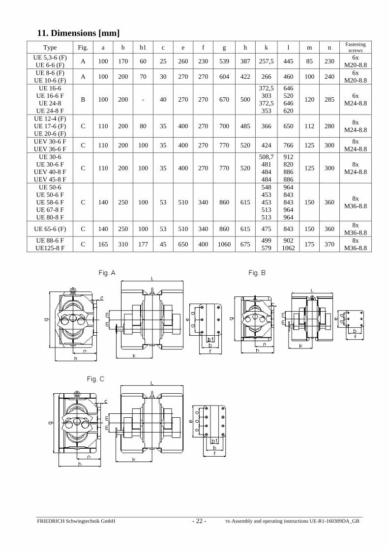
11. Dimensions [mm]
Type Fig. a b b1 c e f g h k l m n Fastening screws
UE 5,3-6 (F) UE 6-6 (F)
A 100 170 60 25 260 230 539 387 257,5 445 85 230 6x
M20-8.8 UE 8-6 (F)
UE 10-6 (F) A 100 200 70 30 270 270 604 422 266 460 100 240
6x M20-8.8
UE 16-6 UE 16-6 F UE 24-8
UE 24-8 F
B 100 200 - 40 270 270 670 500
372,5 303
372,5 353
646 520 646 620
120 285 6x
M24-8.8
UE 12-4 (F) UE 17-6 (F) UE 20-6 (F)
C 110 200 80 35 400 270 700 485 366 650 112 280 8x
M24-8.8
UEV 30-6 F UEV 36-6 F
C 110 200 100 35 400 270 770 520 424 766 125 300 8x
M24-8.8 UE 30-6
UE 30-6 F UEV 40-8 F UEV 45-8 F
C 110 200 100 35 400 270 770 520
508,7 481 484 484
912 820 886 886
125 300 8x
M24-8.8
UE 50-6 UE 50-6 F UE 58-6 F UE 67-8 F UE 80-8 F
C 140 250 100 53 510 340 860 615
548 453 453 513 513
964 843 843 964 964
150 360 8x
M36-8.8
UE 65-6 (F) C 140 250 100 53 510 340 860 615 475 843 150 360 8x
M36-8.8 UE 88-6 F UE125-8 F
C 165 310 177 45 650 400 1060 675 499 579
902 1062
175 370 8x
M36-8.8

FRIEDRICH Schwingtechnik GmbH TK-Assembly and operating instructions UE-R1-160309DA_GB - 23 -
12. Technical data
Type Speed [min-1]
Working torque [kgcm]
min max
Centrifugal force [kN]
min max
Nominal power of drive motor
[KW]
Weight [kg]
min max
Protective boxes
[kg]
UE 5,3-6 (F) 1000 390 540 21,3 29,6 2,2 116 126 16 UE 6-6 (F) 1000 390 620 21,3 34,0 2,2 116 129 16 UE 8-6 (F) 1000 630 860 34,5 47,1 3,0 170 183 20 UE 10-6 (F) 1000 630 1010 34,5 55,4 3,0 170 189 20 UE 16-6 (F) 1000 1010 1600 54,8 87,7 5,5 230 255 27 UE 24-8 (F) 750 1520 2400 46,8 74,0 5,5 263 288 30 UE 12-4 (F) 1500 790 1190 97,4 146,8 15,0 279 297 31 UE 17-6 (F) 1000 1190 1780 65,2 97,6 7,5 308 335 31 UE 20-6 (F) 1000 1190 2040 65,2 111,8 7,5 308 346 31 UE 30-6 (F) 1000 1730 3040 91,1 160,1 11,0 458 515 56 UEV 30-6 F 1000 1730 3040 91,1 160,1 11,0 422 478 40 UEV 36-6 F 1000 1730 3600 91,1 189,5 11,0 422 503 40 UEV 40-8 F 750 2280 4000 70,3 123,3 15,0 454 525 44 UEV 45-8 F 750 2280 4460 70,3 137,5 15,0 454 554 44 UE 50-6 (F) 1000 2830 5100 155,1 279,6 15,0 689 769 50 UE 58-6 F 1000 2830 5880 155,1 322,4 15,0 689 804 50 UE 67-8 F 750 3780 6800 116,5 209,7 15,0 883 939 54 UE 80-8 F 750 3780 7930 116,5 244,5 18,5 883 983 54
UE 65-6 (F) 1000 3000 6640 164,5 364,1 15,0 729 855 50 UE 88-6 F 1000 5580 8800 300,5 482,5 22,0 924 1029 98 UE125-8 F 750 7800 12300 240,5 379,3 22,0 1030 1177 109
13. Lubrication instructions
Important: Unbalance exciter machines are delivered without oil. They must be filled with oil in accordance with the oil level and oil type charts before putting them into operation. Important: The dipstick is only used to check the oil level and must again be replaced with a screwed sealing plug for operating the unbalance exciter. Important: The operation of unbalance exciters is only permitted if the shafts are in a horizontal position.
Please follow the information in the following chapters:
14. Oil change intervals 15. Selection of available gear oils 16. Oil level chart
Important: Only fill or refill with oil after the unbalance exciter or its motor has been switched off and measures have be taken to prevent accidental or unauthorized switching on. Otherwise, there is a danger of knocking or pressing!
The unbalance exciter is equipped with several screwed sealing plugs, a magnetic sealing plug, and a ventilator plug. The magnetic sealing plug is marked with an M. The ventilator plug must be fitted above the oil level of the unbalance exciter, as high as possible. Here, a screwed sealing plug is replaced by the ventilator plug. Depending on the installation position, the magnetic sealing plug is to be used as oil-drain plug. Here, the lowest possible
FRIEDRICH Schwingtechnik GmbH TK-Assembly and operating instructions UE-R1-160309DA_GB - 24 -
position is to be chosen. The metal grit that is produced by the gears during the initial operating time is removed from the oil bath by the magnetic oil-drain plug. All the screwed sealing plugs are provided with a magnet for extracting metal debris from the gearing out of the oil bath occuring during the initial operation period.
The seal rings according to DIN 7603 must be replaced each time the screwed sealing plugs are loosened. There is otherwise the risk of oil leaking and thus damage to the unbalance exciter!
Only high quality doped oils in accordance with DIN 51519 and DIN 51502 are to be used.
If an unbalance exciter is operated using a certain oil from a certain manufacturer and the intention is to change to the same quality oil from a different producer, we recommend the unbalance exciter be completely drained and only then filled up with the new oil as oils are not always mixable due to oil additives that differ according to producers. The oil level depends on the installation situation of the unbalance exciter and is shown in chapter 16. It is important that a quantity of oil should always be visible up to the middle of the dipstick in the unbalance exciter’s housing.
Too much oil in the housing can lead to an oil blockage leading to overheating and damage to the bearings. Moreover the oil runs out. On the other hand, too little oil will lead to seizure and damage to the gearing and the roller bearings.
The oil level should be checked via the dipstick about half an hour after switching off the vibration device.
Important! The oil level should be checked once a month.
When changing the oil, make sur that as much old oil is removed as possible and the metal debris cleaned from the magnetic oil-drain plug.
When filling with oil, ensure that no dirt particles get into the ubalance exciter. Use a funnel with finely woven screen cloth.
Before the appliance is taken into use, check the oil-drain plug and the oil sealing plugs are seated firmly. This should be repeated after 40 hours and later at longer intervals.
13.1 Propeller shaft
Please observe the lubrication intervals as indicated in the operating manual of the manufacturer. As follows are the ongoing lubrication intervals for propeller shafts of the firm FRIEDRICH Schwingtechnik: Ongoing lubrication intervals
Series Articulated joints Shift section GF1 / GF1 short Every 3 months Every 3 months
All others Every 12 months
i
Unfavourable conditions such as temperature, dirt, water or similar could make shorter lubrication intervals necessary. Principally we recommend that the lubrication intervals are adapted to the respective operating conditions.

FRIEDRICH Schwingtechnik GmbH TK-Assembly and operating instructions UE-R1-160309DA_GB - 25 -
14. Oil change intervals
i
We recommend the following oil change intervals:
First oil change after ca. 500 operating hours, no later than three months
Second oil change after ca. 1,000 operating hours, no later than six months
All other oil changes after 1,000 operating hours
The above oil change intervals are reference values. These intervals can be reduced or extended if necessary, according to environmental conditions. Exact oil change intervals can be set on consultation with the oil supplier and the respective oil checks can be carried out by taking occasional samples.
The oil should be changed at shorter intervals if the oil is heavily soiled by unfavourable operating conditions by the time the first oil change is carried out. More frequent oil changes increase the life span of the unbalance exciter.
14.1 Ventilation plug
The ventilation plug must be mounted at the highest point.
i
Because of the vibrations, a slight amount of oil discharge is normal. For the proper functioning of the gear mechanism the ventilation plug must not be obstructed.
i
The functionality of the ventilation plug is to be checked and the ventilation plug cleaned at regular intervals or replaced if necessary by a new one, depending on the amount of dirt and dust at the place of use. We recommend an interval of 4 weeks.
Attention: If dirt causes the ventilation plug to cease functioning properly it can lead to damage to the unbalance exciter, such as oil discharge on the shafts, and the entry of dirt in the bearings. The unbalance exciter's normal pressure equalization during operation then occurs through the gap between the shaft and the bearing plate, instead of through the ventilation plug.
If a substantial amount of oil comes out of the ventilation plug, please check the oil level, mount the ventilation plug at a different position, or change the direction of rotation of the unbalance exciter.

FRIEDRICH Schwingtechnik GmbH TK-Assembly and operating instructions UE-R1-160309DA_GB - 26 -
15. Selection of used gear oils Gear oil with required viscosity is determined according to table 7 depending on
environmental temperatures.
Table 7: Viscocity class depending on environmental and operating temperatures Environmental
temperature Operating temperature Identification to
DIN 51519 Identification to
DIN 51502 °C °C ISO 3498
-40°C to -25°C -10°C to +5°C VG 5 -30°C to -10°C 0°C to +20°C VG 10 -15°C to +20°C +15°C to +50°C VG 68 CLP 68 +15°C to +50°C +45°C to +80°C VG 100 CLP 100
For an ambient temperature of +15 °C to +50 °C, for example, we recommend the following gear oil: Mobilgear 600 XP 100. If different gear oil is used, please ask your oil supplier if the specifications match those of the gear oil we recommend.

FRIEDRICH Schwingtechnik GmbH TK-Assembly and operating instructions UE-R1-160309DA_GB - 27 -
16. Oil level charts 16.1 How to understand the following angle indications
Depending on various mounting options of the unbalance exciters, there are possible various angles of installation, where the dipstick must be used to ensure correct oil level.
Warning! Angle from horizontal plane is decisive, you must add angle of the girder and tilt angle of the machine.
Warning! The illustrated position for the dipstick is an example only. Correct positions are mentioned in the tables.
The ventilator plug must be fitted as high as possible.
+ 50°3
+ 20°
1
Ventilator plug
Horinzontal plane Horinzontal plane
1- 50°
2 - 20°
Ventilator plug
Horizontal plane Horizontal plane

FRIEDRICH Schwingtechnik GmbH TK-Assembly and operating instructions UE-R1-160309DA_GB - 28 -
3
Ventilator plug
Ventilator plug
Position of the dipstick
Horizontal installation = + 90°
Horizontal installation = - 90°
Special position, the dipstick cannot used in this position
1Vertical installation = 0°
Position of the dipstick
Horizontal plane
The dipstick is delivered with maximum length and without marking. It is necessary to provide marking according to the table 8.1 until 8.4 and to cut the dipstick cca 5 mm under the minimum mark.
The unbalance exciters with additional designation F can be installed into various angular positions. Accordingly other positions for the dipstick exist.

FRIEDRICH Schwingtechnik GmbH TK-Assembly and operating instructions UE-R1-160309DA_GB - 29 -
1 3
2
YY
X
Table 8.1 UE 5,3-6 F
UE 6-6 F UE 5,3-6 UE 6-6
UE 16-6 F UE 24-8 F
Oil quantity 0,8 – 3,1 l Oil quantity 0,8 – 1,7 l Oil quantity 1,0 – 5,0 l Install. angle
X [ mm ]
Y [ mm ]
Position dipstick
X [ mm ]
Y [ mm ]
Position dipstick
X [ mm ]
Y [ mm ]
Position dipstick
90° 182 7 3 - - - 267 10 3 85° 173 7 3 - - - 256 10 3 80° 164 7 3 - - - 245 10 3 75° 155 7 3 - - - 235 10 3 70° 146 7 3 - - - 225 10 3 65° 138 8 3 - - - 215 11 3 60° 130 8 3 - - - 206 11 3 55° 121 9 3 - - - 196 12 3 50° 112 9 3 110 13 3 186 13 3 45° 102 10 3 100 14 3 175 14 3 40° 91 7 3 90 15 3 163 15 3 35° 176 7 1 157 10 1 150 17 3 30° 167 7 1 147 10 1 135 20 3 25° 158 7 1 139 10 1 116 22 3 20° 150 7 1 131 10 1 250 10 1 15° 142 7 1 123 10 1 239 10 1 10° 134 7 1 116 11 1 229 10 1 5° 127 8 1 109 11 1 219 11 1 0° 120 8 1 101 12 1 209 11 1 -5° 111 9 1 94 13 1 198 12 1
-10° 103 9 1 86 14 1 188 13 1 -15° 94 10 1 78 15 1 177 14 1 -20° 85 11 1 69 16 1 165 15 1 -25° 73 13 1 60 18 1 151 17 1 -30° 61 14 1 48 20 1 135 20 1 -35° 44 16 1 33 25 1 114 24 1 -40° 339 9 2 14 30 1 87 28 1 -45° 332 10 2 - - - 418 14 2 -50° 326 11 2 - - - 406 15 2 -55° 317 13 2 - - - 392 17 2 -60° 309 14 2 - - - 379 19 2 -65° 296 17 2 - - - 357 24 2 -70° 284 20 2 - - - 336 28 2 -75° 254 30 2 - - - 298 42 2 -80° 225 40 2 - - - 229 56 2 -85° 116 79 2 - - - - - -

FRIEDRICH Schwingtechnik GmbH TK-Assembly and operating instructions UE-R1-160309DA_GB - 30 -
1 3
2
YY
X
Table 8.2
UE 8-6 F UE 10-6 F
UE 8-6 UE 10-6
UE 12-4 F UE 17-6 F UE 20-6 F
Oil quantity 1,1 – 5,3 l Oil quantity 1,1 – 1,9 l Oil quantity 2,2 – 5,2 l Install. angle
X [ mm ]
Y [ mm ]
Position dipstick
X [ mm ]
Y [ mm ]
Position dipstick
X [ mm ]
Y [ mm ]
Position dipstick
90° 223 8 3 - - - 242 9 3 85° 213 8 3 - - - 229 9 3 80° 203 8 3 - - - 216 9 3 75° 193 8 3 - - - 203 10 3 70° 184 8 3 - - - 190 10 3 65° 175 9 3 - - - 179 11 3 60° 166 9 3 - - - 168 11 3 55° 156 10 3 - - - 154 12 3 50° 146 10 3 140 14 3 141 12 3 45° 135 11 3 130 15 3 125 15 3 40° 124 12 3 120 16 3 236 9 1 35° 112 14 3 206 10 1 223 9 1 30° 210 8 1 194 10 1 211 9 1 25° 200 8 1 185 10 1 200 10 1 20° 190 8 1 176 10 1 190 10 1 15° 181 8 1 167 10 1 180 10 1 10° 172 8 1 158 11 1 170 10 1 5° 163 9 1 150 11 1 159 11 1 0° 154 9 1 140 12 1 149 11 1 -5° 144 10 1 132 13 1 139 12 1
-10° 135 10 1 124 14 1 128 12 1 -15° 124 11 1 113 15 1 116 13 1 -20° 114 12 1 102 16 1 104 14 1 -25° 100 14 1 90 17 1 88 17 1 -30° 87 16 1 75 20 1 73 19 1 -35° 64 19 1 57 25 1 51 22 1 -40° 41 23 1 32 30 1 453 12 2 -45° 386 11 2 - - - 444 14 2 -50° 378 12 2 - - - 436 15 2 -55° 368 14 2 - - - 425 17 2 -60° 358 16 2 - - - 414 19 2 -65° 343 19 2 - - - 397 23 2 -70° 328 23 2 - - - 380 27 2 -75° 292 35 2 - - - 340 41 2 -80° 257 46 2 - - - 301 55 2 -85° 127 92 2 - - - 156 109 2

FRIEDRICH Schwingtechnik GmbH TK-Assembly and operating instructions UE-R1-160309DA_GB - 31 -
1 3
2
YY
X
Table 8.3
UE 17-6 UE 20-6
UEV 30-6 F UEV 40-8 F UEV 36-6 F UEV 45-8 F
UE 30-6 UE 40-8
Oil quantity 2,2 – 3,4 l Oil quantity 2,6 – 5,2 l Oil quantity 2,6 – 5,2 l Install. angle
X [ mm ]
Y [ mm ]
Position dipstick
X [ mm ]
Y [ mm ]
Position dipstick
X [ mm ]
Y [ mm ]
Position dipstick
90° - - - 268 10 3 - - - 85° - - - 254 10 3 - - - 80° - - - 241 10 3 - - - 75° - - - 229 11 3 - - - 70° - - - 217 11 3 - - - 65° - - - 204 12 3 - - - 60° - - - 192 12 3 - - - 55° - - - 179 13 3 - - - 50° 147 13 3 166 14 3 173 13 3 45° 133 14 3 150 15 3 160 14 3 40° 118 15 3 135 16 3 145 15 3 35° 219 10 1 239 10 1 235 10 1 30° 207 10 1 225 10 1 222 10 1 25° 196 10 1 213 10 1 208 10 1 20° 186 10 1 201 10 1 196 10 1 15° 176 10 1 189 11 1 185 10 1 10° 166 11 1 178 11 1 174 11 1 5° 156 11 1 167 12 1 163 11 1 0° 146 12 1 156 12 1 152 12 1 -5° 136 13 1 144 13 1 140 13 1
-10° 126 14 1 132 13 1 130 14 1 -15° 115 15 1 119 15 1 118 15 1 -20° 104 16 1 106 16 1 105 16 1 -25° 90 18 1 88 18 1 90 18 1 -30° 75 21 1 70 20 1 73 20 1 -35° 54 25 1 46 24 1 51 24 1 -40° 28 30 1 493 14 2 25 31 1 -45° - - - 482 15 2 - - - -50° - - - 471 16 2 - - - -55° - - - 458 19 2 - - - -60° - - - 442 21 2 - - - -65° - - - 424 26 2 - - - -70° - - - 398 30 2 - - - -75° - - - 359 40 2 - - - -80° - - - 286 59 2 - - - -85° - - - - - - - - -

FRIEDRICH Schwingtechnik GmbH TK-Assembly and operating instructions UE-R1-160309DA_GB - 32 -
1 3
2
YY
X
Table 8.4
UE 50-6 F UE 67-8 F UE 58-6 F UE 65-6 F UE 80-8 F
UE 65-6 UE 88-6 F
UE 125-8 F
Oil quantity 2,6 – 14,2 l Oil quantity 2,6 – 5,2 l Oil quantity 4,0 – 13,7 l Install. angle
X [ mm ]
Y [ mm ]
Position dipstick
X [ mm ]
Y [ mm ]
Position dipstick
X [ mm ]
Y [ mm ]
Position dipstick
90° 322 6 3 - - - 377 5 3 85° 307 6 3 - - - 360 6 3 80° 293 6 3 - - - 344 6 3 75° 279 6 3 - - - 329 6 3 70° 265 6 3 - - - 313 7 3 65° 251 6 3 - - - 299 7 3 60° 238 7 3 - - - 284 7 3 55° 224 7 3 - - - 269 7 3 50° 211 8 3 215 15 3 254 7 3 45° 194 8 3 200 15 3 238 8 3 40° 178 8 3 185 16 3 220 8 3 35° 159 8 3 265 10 1 200 9 3 30° 136 10 3 250 10 1 176 11 3 25° 241 6 1 240 10 1 147 13 3 20° 228 6 1 225 10 1 108 15 3 15° 216 6 1 210 11 1 284 6 1 10° 203 6 1 200 11 1 269 6 1 5° 191 6 1 190 12 1 254 6 1 0° 179 6 1 175 12 1 239 6 1 -5° 167 6 1 165 13 1 224 7 1
-10° 153 7 1 150 14 1 209 7 1 -15° 139 8 1 140 15 1 194 7 1 -20° 123 9 1 125 17 1 178 8 1 -25° 104 10 1 110 20 1 160 9 1 -30° 82 11 1 90 23 1 140 10 1 -35° 52 17 1 65 30 1 117 11 1 -40° 574 7 2 30 38 1 88 12 1 -45° 562 7 2 - - - 48 15 1 -50° 549 8 2 - - - 616 8 2 -55° 535 9 2 - - - 600 10 2 -60° 518 10 2 - - - 583 11 2 -65° 498 12 2 - - - 562 12 2 -70° 472 14 2 - - - 534 16 2 -75° 432 19 2 - - - 492 23 2 -80° 360 27 2 - - - 419 29 2 -85° 156 51 2 - - - 211 58 2

FRIEDRICH Schwingtechnik GmbH TK-Assembly and operating instructions UE-R1-160309DA_GB - 33 -
17. Spare parts and repairs, maintenance intervals
17.1 Spare parts
Only use original spare parts or spare parts that conform to suitable standards. Ordering spare parts In order to ensure that the correct spare parts are delivered, they must be identified precisely using the operating manual and the relevant spare parts list before placing the order. This will prevent unnecessary delays, the delivery of the wrong parts, and enquiries at the customer by FRIEDRICH Schwingtechnik.
Contact:
Phone: +49 (0)2129 3790-0
Fax: +49 (0)2129 3790-37
E-mail: [email protected]
When placing the order indicate the following:
The unbalance exciter type and serial number. This information can be taken from the nameplate.
The name of the part in the spare parts list.
Important! Please do not forget to indicate the number or the quantity of the spare parts to be supplied.
17.2 Repairs
i
Have the unbalance exciter repaired by the manufacturer FRIEDRICH-Schwingtechnik.
Make sure that original spare parts are used if the motor is repaired by an external
workshop. FRIEDRICH-Schwingtechnik will not guarantee or assume continued liability for the proper functioning of the unbalance exciter if no original spare parts are installed.
We recommend you always replace all bearings when replacing the bearings, even if
only one bearing is defective. A defective bearing will always cause other bearings to become damaged too. The other bearings will fail within a short time.
After every second bearing replacement, the bearing plates must be replaced too.

FRIEDRICH Schwingtechnik GmbH TK-Assembly and operating instructions UE-R1-160309DA_GB - 34 -
17.3 Maintenance
To guarantee a longer lifetime for the unbalance exciter we recommend a maintenance interval of 3 years!
Have the maintenance work done by an expert company, or directly at the manufacturer FRIEDRICH – Schwingtechnik.
Clean or regularly replace the ventilation plugs
Only use original spare parts
18. Warranty
For all new unbalance exciters FRIEDRICH provides a warranty of 1 year from the date of delivery.
The warranty will expire if: The motor is used for purposes other than the intended. The unbalance exciter is operated without oil, with too little oil, or with the wrong oil. The unbalance exciter is operated with the wrong unbalance setting.
The unbalance exciter is operated at a defective machine.
The unbalance exciter was not correctly connected up.
Modifications were made to the unbalance exciter which could have an influence on the performance of the unbalance exciter.
The unbalance exciter was operated without centrifugal plate and protective boxes.
Damage occurred during transport.
The unbalance exciter has not been mounted in accordance with the instructions given in section 6.
So if in doubt, have the unbalance exciter repaired by the manufacturer FRIEDRICH-Schwingtechnik.
i

FRIEDRICH Schwingtechnik GmbH TK-Assembly and operating instructions UE-R1-160309DA_GB - 35 -
19. Declaration of incorporation within the meaning of EU Machines Directives (2006/42/EC Article 6 Paragraph (2) ; Annex ll 1.B) for installable machines, amended by Directive 2006/42/EC with special reference to Annex I. Herewith declares the manufacturer Company/Name/Address: FRIEDRICH Schwingtechnik GmbH P.O. Box 10 16 44 D-42760 Haan of the incomplete machine Product/Type: FRIEDRICH unbalance exciter Type: UE … -.- …
that this has been developed, built and manufactured in conformity with the following directive:
Machine Directive (2006/42/EG)
and meet the following basic requirements of the directive:
Annex I, Articles 1.1.2, 1.1.5, 1.3.2, 1.3.3, 1.3.7, 1.7.3
The following harmonised standards have been applied:
DIN EN ISO 12100 Part 1 and 2. Safety of Machines, Equipment and Installations
For this product the special technical documents were prepared in accordance with annex VII Part B. Complete technical documentation exists. Upon justifiable request, these documents from individual national location can be send by post, email or fax. Operating-/installation instructions are available. The safety instructions provided in the operating-/installation instructions must be observed. Authorised representative to assemble and transmission of the technical documents: Bernd Daus, Friedrich Schwingtechnik GmbH, Am Höfgen24, D-42781 Haan It is forbidden to start up this machine/this machine part until it has been established that the machine in which the unbalance exciter is to be installed complies with the regulations of the directive (2006/42/EG). City / Date of Issue Signature and Function of the Signer Haan Dipl.-Ing., Dipl.-Wirt.Ing. Martin Gerth
Managing Director