assembly and operating manual mcs 12
TRANSCRIPT

Translation of operating manual
Assembly and Operating ManualMCS 12Controller for SCHUNK gripper and rotation modules

Imprint
202.00 | MCS 12 | Assembly and Operating Manual | en | 0389675
ImprintCopyright:This manual is protected by copyright. The author is SCHUNK GmbH & Co. KG. All rights re-served. Any reproduction, processing, distribution (making available to third parties),translation or other usage - even excerpts - of the manual is especially prohibited and re-quires our written approval.
Technical changes:We reserve the right to make alterations for the purpose of technical improvement.
Document number: 0389675
Version: 02.00 | 22/01/2018 | en
© SCHUNK GmbH & Co. KGAll rights reserved.
Dear Customer,thank you for trusting our products and our family-owned company, the leading techno-logy supplier of robots and production machines.Our team is always available to answer any questions on this product and other solutions.Ask us questions and challenge us. We will find a solution!Best regards,Your SCHUNK team
SCHUNK GmbH & Co. KGSpann- und GreiftechnikBahnhofstr. 106 – 134D-74348 Lauffen/NeckarTel. +49-7133-103-0Fax [email protected]

Table of contents
02.00 | MCS 12 | Assembly and Operating Manual | en | 0389675
3
Table of contents1 General.................................................................................................................... 5
1.1 About this manual ................................................................................................ 51.1.1 Presentation of Warning Labels ............................................................... 51.1.2 Applicable documents .............................................................................. 6
1.2 Warranty .............................................................................................................. 61.3 Scope of delivery .................................................................................................. 6
2 Basic safety notes ................................................................................................... 72.1 Appropriate use.................................................................................................... 72.2 Inappropriate use ................................................................................................. 72.3 Constructional changes ........................................................................................ 72.4 Spare parts ........................................................................................................... 72.5 Environmental and operating conditions ............................................................. 8
2.5.1 Electromagnetic compatibility.................................................................. 82.6 Personnel qualification....................................................................................... 102.7 Personal protective equipment.......................................................................... 112.8 Notes on safe operation ..................................................................................... 112.9 Disposal .............................................................................................................. 112.10 Malfunctions....................................................................................................... 122.11 Transport ............................................................................................................ 122.12 Fundamental dangers......................................................................................... 13
2.12.1 Protection during handling and assembly .............................................. 132.12.2 Protection during commissioning and operation ................................... 142.12.3 Protection against dangerous movements............................................. 142.12.4 Protection against electric shock............................................................ 152.12.5 Protection against magnetic and electromagnetic fields ....................... 162.12.6 Protection against burns ........................................................................ 16
3 Technical data......................................................................................................... 173.1 ID Number .......................................................................................................... 173.2 Basic Data ........................................................................................................... 173.3 Specific Data ....................................................................................................... 183.4 Housing dimensions ........................................................................................... 183.5 Digital Inputs and Outputs.................................................................................. 19
4 Design and description............................................................................................ 204.1 Design ................................................................................................................. 204.2 Description ......................................................................................................... 21
5 Assembly ................................................................................................................ 225.1 Mechanical assembly ......................................................................................... 225.2 Connection diagram ........................................................................................... 23

Table of contents
402.00 | MCS 12 | Assembly and Operating Manual | en | 0389675
5.3 Electrical connection .......................................................................................... 235.3.1 Observe ERS when connecting a rotary module .................................... 255.3.2 Connecting the Controller ...................................................................... 265.3.3 Terminal Strip X1 .................................................................................... 275.3.4 Terminal Strip X2 .................................................................................... 275.3.5 Terminal Strip X3 .................................................................................... 295.3.6 Communication Interfaces ..................................................................... 30
6 Functional description ............................................................................................ 326.1 Display Elements ................................................................................................ 326.2 Restoring the Factory Settings (DEFAULT Function)........................................... 336.3 Writing Firmware (BOOT Function) .................................................................... 34
7 Start-up and System Integration ............................................................................. 357.1 Compatibility ...................................................................................................... 357.2 Configuration with the Motion Tool Schunk (MTS) ............................................ 35
7.2.1 The Module is in its Delivered State ....................................................... 357.2.2 The module has been reset to its DEFAULT values................................. 40
7.3 Start-up............................................................................................................... 467.4 Start-up of the Digital Inputs .............................................................................. 477.5 Start-up of the Digital Outputs ........................................................................... 477.6 System Integration ............................................................................................. 47
7.6.1 SCHUNK Motion protocol ....................................................................... 477.6.2 System Structure .................................................................................... 48
8 Trouble shooting..................................................................................................... 498.1 LEDs on Controller Do Not Light Up ................................................................... 498.2 RDY LED (Green) Does Not Light Up ................................................................... 498.3 LED POW (green) doesn't light up or is only slightly illuminated ....................... 498.4 LED ERR (red) lights up and LED RDY (green) doesn't......................................... 498.5 Communication failure ....................................................................................... 50
9 Maintenance and care ............................................................................................ 51
10 Appendix ................................................................................................................ 52
General
02.00 | MCS 12 | Assembly and Operating Manual | en | 0389675
5
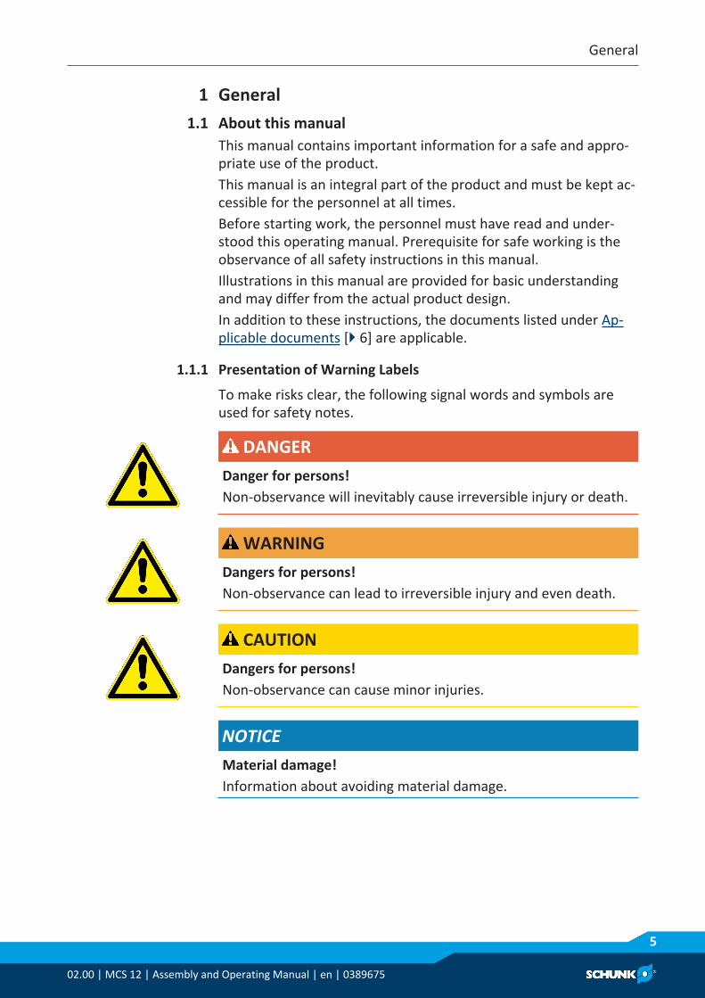
1 General1.1 About this manual
This manual contains important information for a safe and appro-priate use of the product.This manual is an integral part of the product and must be kept ac-cessible for the personnel at all times.Before starting work, the personnel must have read and under-stood this operating manual. Prerequisite for safe working is theobservance of all safety instructions in this manual.Illustrations in this manual are provided for basic understandingand may differ from the actual product design.In addition to these instructions, the documents listed under Ap-plicable documents [} 6] are applicable.
1.1.1 Presentation of Warning Labels
To make risks clear, the following signal words and symbols areused for safety notes.
DANGERDanger for persons!Non-observance will inevitably cause irreversible injury or death.
WARNINGDangers for persons!Non-observance can lead to irreversible injury and even death.
CAUTIONDangers for persons!Non-observance can cause minor injuries.
NOTICEMaterial damage!Information about avoiding material damage.

General
602.00 | MCS 12 | Assembly and Operating Manual | en | 0389675
1.1.2 Applicable documents
• General terms of business*• Catalog data sheet of the purchased product *• Assembly and operating manuals of the accessories *• Software manual "Motion Control SCHUNK" *The documents marked with an asterisk (*) can be downloaded onour homepage schunk.com
1.2 WarrantyIf the product is used as intended, the warranty is valid for 24months from the ex-works delivery date under the following con-ditions:• Observe the ambient conditions and operating conditions, En-
vironmental and operating conditions [} 8]
1.3 Scope of deliveryThe scope of delivery includes• Controller MCS 12• Accessory pack• USB to RS232 converter• 9-pin SUB-D cable (1:1)• DVD
Contents of DVD:Contents of the DVD enclosed with the MCS 12 controller:• Configuration and start-up tool "Motion Tool Schunk (MTS)"• EEPROM files for MCS 12 controller• Assembly and Operating Manual• FB 20 function module for Siemens S7 3007400 for controlling
SCHUNK products• Software Manual "Motion Control Schunk"

Basic safety notes
02.00 | MCS 12 | Assembly and Operating Manual | en | 0389675
7
2 Basic safety notes2.1 Appropriate use
The product is used to control and regulate the EGN and EZN grip-pers as well as the ERS rotary module.• The product is designed to be built into a control cabinet. The
applicable guidelines must be observed and complied with.• The product may only be used within the scope of its technical
data, Technical data [} 17].• The product is intended for industrial use.• Appropriate use of the product includes compliance with all in-
structions in this manual.
2.2 Inappropriate useIt is considered improper use if the product is used to actuate orcontrol products that are not from SCHUNK GmbH & Co. KG.• Any utilization that exceeds or differs from the appropriate use
is regarded as misuse.
2.3 Constructional changesImplementation of structural changesBy conversions, changes, and reworking, e.g. additional threads,holes, or safety devices can impair the functioning or safety of theproduct or damage it.• Structural changes should only be made with the written ap-
proval of SCHUNK.
2.4 Spare partsUse of unauthorized spare partsUsing unauthorized spare parts can endanger personnel and dam-age the product or cause it to malfunction.• Use only original spare parts or spares authorized by SCHUNK.
Basic safety notes
802.00 | MCS 12 | Assembly and Operating Manual | en | 0389675
2.5 Environmental and operating conditionsRequired ambient conditions and operating conditionsIncorrect ambient and operating conditions can make the productunsafe, leading to the risk of serious injuries, considerable materialdamage and/or a significant reduction to the product's life span.• Make sure that the product is used only in the context of its
defined application parameters, Technical data [} 17].• Ensure that the product is protected against sprayed water, va-
pors, contamination, and EMC influences during operation. Ex-ceptions are products that are designed especially for contamin-ated environments.
2.5.1 Electromagnetic compatibility
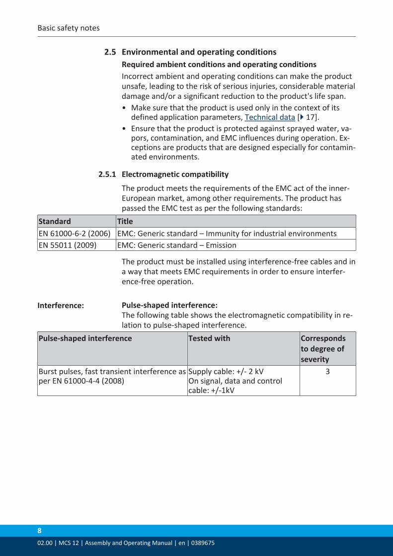
The product meets the requirements of the EMC act of the inner-European market, among other requirements. The product haspassed the EMC test as per the following standards:
Standard TitleEN 61000-6-2 (2006) EMC: Generic standard – Immunity for industrial environmentsEN 55011 (2009) EMC: Generic standard – Emission
The product must be installed using interference-free cables and ina way that meets EMC requirements in order to ensure interfer-ence-free operation.
Interference: Pulse-shaped interference: The following table shows the electromagnetic compatibility in re-lation to pulse-shaped interference.
Pulse-shaped interference Tested with Correspondsto degree ofseverity
Burst pulses, fast transient interference asper EN 61000-4-4 (2008)
Supply cable: +/- 2 kVOn signal, data and controlcable: +/-1kV
3

Basic safety notes
02.00 | MCS 12 | Assembly and Operating Manual | en | 0389675
9
Sinusoidal interference: The following table shows the electromagnetic compatibility in re-lation to sinusoidal interference.
Sinusoidal interference Test values Correspondsto degree ofseverity
HF radiation (electromagnetic fields) as per EN 61000-4-3
80% amplitude modulation at 1 kHz to10 V/m in the range of 80 … 1000 MHz to3 V/m in the range of 1.4 … 2 GHz to 1 V/m in the range of 2 … 2.7 GHz
3
HF energization on cables andcable shielding as per EN 61000-4-6
Test voltage 10 V with amplitude modula-tion80% of 1 kHz in the range of 150 kHz … 80 MHz
3
Emission of radio in-terference
The following table shows the interference emission from electro-magnetic fields as per EN 55011 (2009), limit class A, group 1,measured at a distance of 3 m.
Interference Value30 … 230 MHz230 … 1000MHz
< 50 dB (µV) quasi-peak, measured at a dis-tance of 3 m< 57 dB (µV) quasi-peak, measured at a dis-tance of 3 m

Basic safety notes
1002.00 | MCS 12 | Assembly and Operating Manual | en | 0389675
2.6 Personnel qualificationInadequate qualifications of the personnelIf the personnel working with the product is not sufficiently quali-fied, the result may be serious injuries and significant propertydamage.• All work may only be performed by qualified personnel.• Before working with the product, the personnel must have read
and understood the complete assembly and operating manual.• Observe the national safety regulations and rules and general
safety instructions.
The following personal qualifications are necessary for the variousactivities related to the product:
Trained electrician Due to their technical training, knowledge and experience, trainedelectricians are able to work on electrical systems, recognize andavoid possible dangers and know the relevant standards and regu-lations.
Qualified personnel Due to its technical training, knowledge and experience, qualifiedpersonnel is able to perform the delegated tasks, recognize andavoid possible dangers and knows the relevant standards and reg-ulations.
Instructed person Instructed persons were instructed by the operator about the del-egated tasks and possible dangers due to improper behaviour.
Service personnel ofthe manufacturer
Due to its technical training, knowledge and experience, servicepersonnel of the manufacturer is able to perform the delegatedtasks and to recognize and avoid possible dangers.

Basic safety notes
02.00 | MCS 12 | Assembly and Operating Manual | en | 0389675
11
2.7 Personal protective equipmentUse of personal protective equipmentPersonal protective equipment serves to protect staff againstdanger which may interfere with their health or safety at work.• When working on and with the product, observe the occupa-
tional health and safety regulations and wear the required per-sonal protective equipment.
• Observe the valid safety and accident prevention regulations.• Wear protective gloves to guard against sharp edges and
corners or rough surfaces.• Wear heat-resistant protective gloves when handling hot sur-
faces.• Wear protective gloves and safety goggles when handling haz-
ardous substances.• Wear close-fitting protective clothing and also wear long hair in
a hairnet when dealing with moving components.
2.8 Notes on safe operationIncorrect handling of the personnelIncorrect handling and assembly may impair the product's safetyand cause serious injuries and considerable material damage.• Avoid any manner of working that may interfere with the func-
tion and operational safety of the product.• Use the product as intended.• Observe the safety notes and assembly instructions.• Do not expose the product to any corrosive media. This does
not apply to products that are designed for special environ-ments.
• Eliminate any malfunction immediately.• Observe the care and maintenance instructions.• Observe the current safety, accident prevention and environ-
mental protection regulations regarding the product's applica-tion field.
2.9 DisposalHandling of disposalThe incorrect handling of disposal may impair the product's safetyand cause serious injuries as well as considerable material and en-vironmental harm.• Follow local regulations on dispatching product components for
recycling or proper disposal.
Basic safety notes
1202.00 | MCS 12 | Assembly and Operating Manual | en | 0389675
2.10 MalfunctionsBehavior in case of malfunctions• Immediately remove the product from operation and report the
malfunction to the responsible departments/persons.• Order appropriately trained personnel to rectify the malfunc-
tion.• Do not recommission the product until the malfunction has
been rectified.• Test the product after a malfunction to establish whether it still
functions properly and no increased risks have arisen.
2.11 TransportHandling during transportIncorrect handling during transport may impair the product'ssafety and cause serious injuries and considerable material dam-age.• When handling heavy weights, use lifting equipment to lift the
product and transport it by appropriate means.• Secure the product against falling during transportation and
handling.• Stand clear of suspended loads.

Basic safety notes
02.00 | MCS 12 | Assembly and Operating Manual | en | 0389675
13
2.12 Fundamental dangersGeneral• Observe safety distances.• Never deactivate safety installations.• Install the provided protective product in the danger zone be-
fore switching on the product.• Remove the energy supplies before installation, modification,
maintenance, or adjustment work. Ensure there is no residualenergy in the system.
• Do not move parts by hand while the energy supply is connec-ted.
• Do not reach into the movement area of the product during op-eration.
2.12.1 Protection during handling and assembly
Incorrect handling and assemblyIncorrect handling and assembly may impair the product's safetyand cause serious injuries and considerable material damage.• Have all work carried out by appropriately qualified personnel.• For all work, secure the product against accidental operation.• Observe the relevant accident prevention rules.• Use suitable assembly and transport equipment and take pre-
cautions to prevent jamming and crushing.Incorrect lifting of loadsFalling loads may cause serious injuries and even death.• Stand clear of suspended loads and do not step into their swiv-
eling range.• Never move loads without supervision.• Do not leave suspended loads unattended.

Basic safety notes
1402.00 | MCS 12 | Assembly and Operating Manual | en | 0389675
2.12.2 Protection during commissioning and operation
Falling or violently ejected componentsFalling and violently ejected components can cause serious injuriesand even death.• Take appropriate protective measures to secure the danger
zone.• Never step into the danger zone during operation.
2.12.3 Protection against dangerous movements
Unexpected movementsResidual energy in the system may cause serious injuries whileworking with the product.• Switch off the energy supply, ensure that no residual energy re-
mains and secure against inadvertent reactivation.• The faulty actuation of conected drives may cause dangerous
movements.• Operating mistakes, faulty parameterization during commission-
ing or software errors may trigger dangerous movements.• Never rely solely on the response of the monitoring function to
avert danger. Until the installed monitors become effective, itmust be assumed that the drive movement is faulty, with its ac-tion being dependent on the control unit and the current oper-ating condition of the drive. Perform maintenance work, modi-fications, and attachments outside the danger zone defined bythe movement range.
• To avoid accidents and/or material damage, human access tothe movement range of the machine must be restricted. Limit/prevent accidental access for people in this area due throughtechnical safety measures. The protective cover and protectivefence must be rigid enough to withstand the maximum possiblemovement energy. EMERGENCY STOP switches must be easilyand quickly accessible. Before starting up the machine or auto-mated system, check that the EMERGENCY STOP system isworking. Prevent operation of the machine if this protectiveequipment does not function correctly.

Basic safety notes
02.00 | MCS 12 | Assembly and Operating Manual | en | 0389675
15
2.12.4 Protection against electric shock
Work on electrical equipmentTouching live parts may result in death.• Work on the electrical equipment may only be carried out by
qualified electricians in accordance with the electrical engineer-ing regulations.
• Lay electrical cables properly, e. g. in a cable duct or a cablebridge. Observe standards.
• Before connecting or disconnecting electrical cables, switch offthe power supply and check that the cables are free of voltage.Secure the power supply against being switched on again.
• Before switching on the product, check that the protectiveearth conductor is correctly attached to all electrical compon-ents according to the wiring diagram.
• Check whether covers and protective devices are fitted to pre-vent contact with live components.
• Do not touch the product's terminals when the power supply isswitched on.
Possible electrostatic energyComponents or assembly groups may become electrostaticallycharged. When the electrostatic charge is touched, the dischargemay trigger a shock reaction leading to injuries.• The operator must ensure that all components and assembly
groups are included in the local potential equalisation in accord-ance with the applicable regulations.
• While paying attention to the actual conditions of the workingenvironment, the potential equalisation must be implementedby a specialist electrician according to the applicable regula-tions.
• The effectiveness of the potential equalisation must be verifiedby executing regular safety measurements.

Basic safety notes
1602.00 | MCS 12 | Assembly and Operating Manual | en | 0389675
2.12.5 Protection against magnetic and electromagnetic fields
Work in areas with magnetic and electromagnetic fieldsMagnetic and electromagnetic fields can lead to serious injuries.• Persons with pace-makers, metal implants, metal shards, or
hearing aids require the consent of a physician before enteringareas in which components of the electric drive and control sys-tems are mounted, started up, and operated.
• Persons with pace-makers, metal implants, metal shards, orhearing aids require the consent of a physician before enteringareas in which magnetic grippers or motor parts with perman-ent magnets are stored, repaired, or assembled.
• Do not operate high-frequency or radio devices in the proximityof electric components of the drive system and their feed lines.If the use of such devices is necessary:When starting up the electric drive and control system, checkthe machine or automated system for possible failures whensuch systems are used at different intervals and in differentstates of the control system. A special additional EMC test maybe necessary if the system has a high risk potential.
2.12.6 Protection against burns
Working with hot surfacesDepending on the circumstances the surface of the product canget very hot and cause burns when touching it.• Do not touch hot surfaces, such as brake resistors, heat sinks,
drive units, windings and sheet metals.• Let the surface cool down before working with it. After switch-
ing off the cool-down time of some components can average upto an hour.
• Wear protection gloves.

Technical data
02.00 | MCS 12 | Assembly and Operating Manual | en | 0389675
17
3 Technical data3.1 ID Number
Designation MCS 12ID number EGN 80 0307020
EGN 100 0307021EGN 160 0307022EZN 64 0307030EZN 100 0307031ERS 135 0307035ERS 170 0307036ERS 210 0307037
3.2 Basic DataDesignation MCS 12Mechanical operating dataWeight [kg] 0.98IP rating IP30Ambient temperature [°C]Min.Max.
545
Supported transducer types Encoder, resolverControl types PI current control
PI velocity controlPI position control
Electrical operating data (power)Power supply [VDC] 24 or 48 ± 10% (ERS)Nominal power current [A] Max.
1224
Electrical operating data (logic)Power supply [VDC] 24 ± 10%Nominal power current [A] 0.5InterfaceProfibus (1.5 MBaud) XRS232 (9,600 kBaud) XCAN (max. 1 MBaud) X

Technical data
1802.00 | MCS 12 | Assembly and Operating Manual | en | 0389675
3.3 Specific DataDesignation MCS 12
Nominal current (I nom) [A] Maximum current (I max) [A]
EGN 80 1.04.0
EGN 100 1.84.0
EGN 160 2.64.0
EZN 64 1.44.0
EZN 100 2.24.0
ERS 135 4.1613.0
ERS 170 5.219.8
ERS 210 6.216.0
3.4 Housing dimensions
Housing dimensions (mm)

Technical data
02.00 | MCS 12 | Assembly and Operating Manual | en | 0389675
19
3.5 Digital Inputs and OutputsDesignation MCS 12Digital OutputsType of outputsystem opto-decoupledOutput voltage, Uout [VDC] >12Electric framework GNDElectric currentMax. [mA] >3Short-circuit-proof yesInverse-polarity protection yesOpto-decoupled yesDigital InputsThreshold level 'High'[VDC] >3Threshold level 'Low' [VDC] <0.5Power consumption [mA] <5Inverse-polarity protection yesOpto-decoupled yes

Design and description
2002.00 | MCS 12 | Assembly and Operating Manual | en | 0389675
4 Design and description4.1 Design
Design of the controller
Item Description Function1 Terminal strip X1 Used to connect the module motor phases and supply
power to the controller2 POW LED (green) Power voltage supply indicator3 RS232 interface RS232 connection4 Terminal strip X3 Used to connect differential encoders, resolvers, Hall-ef-
fect sensors5 Terminal strip X2 Used to connect brakes, differential encoders, logic
voltage supply, digital inputs and outputs6 Profibus DP interface Used to connect Profibus DP7 CAN bus interface Used to connect CAN bus8 ERR LED (red) Error indicator9 RDY LED (green) Indicates when the module is ready to communicate with
the higher-level control unit

Design and description
02.00 | MCS 12 | Assembly and Operating Manual | en | 0389675
21
Terminal strip X1
4.2 DescriptionThe controller is designed to activate and control EVG, EGN andEZN grippers or the ERS rotary module.The MCS 12 controller does not include temperature monitoringwith KTY84.Depending on the field bus system, up to 255 modules can be con-nected to each other.

Assembly
2202.00 | MCS 12 | Assembly and Operating Manual | en | 0389675
5 Assembly5.1 Mechanical assembly
NOTICEMaterial damage due to improper assembly!Splash water, vapors, contamination, overheating and EMC im-pact may cause damage to the controller.• Install the controller in a control cabinet that meets at least
the requirements of protection class IP54.• Mount the controller horizontally.• Protect the controller from foreign bodies.• Observe assembly distances.• Do not cover the louvers located on the side between the
printed circuit board carrier and protection cover.
Assembly distances in the control cabinet (mm)

Assembly
02.00 | MCS 12 | Assembly and Operating Manual | en | 0389675
23
5.2 Connection diagram
Control unitOut
FBField bus (FB)
Powersupply
Module
LogicvoltagePowervoltage
IN IN
MCS 12 MCS 12
FB
Transducer
Motor
Connecting plug (CP) CP
Connection Diagram
5.3 Electrical connection
DANGERRisk of fatal injuries due to electric shock!• Always disconnect the logic voltage and motor voltage before
performing any work on the controller.• Do not carry out work on the controller before the intermedi-
ate circuit voltage has dropped to a residual voltage of below10 V.
• It can be measured at terminal strip X1 between +24 V (+48 VERS) and GND.
WARNINGRisk of injury when the machine/system moves unexpectedly!Switch off power supply.
NOTICEMaterial damage due to faulty connection!Electronic components can be damaged in case of all-pole discon-nection.

Assembly
2402.00 | MCS 12 | Assembly and Operating Manual | en | 0389675
NOTEObserve the cable dimensions for the cables, sensors and trans-ducers of the connected module. The required information can befound in the operating manual for the module in question.
NOTEThe wiring diagrams and the cable dimensions for the cables, tem-perature sensors and shaft encoders on the ERS must be observedTechnical data [} 17].
NOTEIf the logic and power voltages are supplied by a voltage source,the logic and power must be shielded separately. Equipotentialbonding must be provided between the voltage sources for logicand power.

Assembly
02.00 | MCS 12 | Assembly and Operating Manual | en | 0389675
25
5.3.1 Observe ERS when connecting a rotary module
NOTICEMaterial damage through regenerative energy!Under great loads, regenerative energy (electric energy from gen-erator effect) may build up and damage the regulator.• Ensure discharge of regenerative energy on customer's
premises.• SCHUNK recommends the use of a brake chopper
(Type: ACC3EA001 ID number 9951504).• Adjust the response threshold of the brake chopper used.✓At 48 VDC operation, set the brake chopper to 53 VDC or "C"
NOTEThe stepper mode of the MCS 12 controller is used for commuta-tion. In this mode, all three phases are energized when the con-troller is switched on. This directs the rotor's magnetic field to-ward that of the stator, causing the drive to jump a few degrees.The resulting change in position is measured using the transducerand saved as the offset in the controller's memory. To increasethe accuracy of this offset, the phases are energized several timesin succession.As such, the motor may jump in the +/- 30° range after the con-troller is switched on. In incremental measuring systems, thisstepper mode is carried out each time the controller is restarted.

Assembly
2602.00 | MCS 12 | Assembly and Operating Manual | en | 0389675
5.3.2 Connecting the Controller
Several modules are connected using connecting plugs with ter-mination resistors. The termination resistor must be set on the lastbus node.
NOTEWhen establishing the electrical connections, observe the connec-tion diagram, Appendix [} 52].
■ The module is installed■ The master (higher-level control unit) is installedØ Connect the connecting plug to the master.Ø Connect the connecting plug to the controller.Ø Connect any other bus nodes to the connecting plug.Ø Connect the termination resistor to the connecting plug if the
controller is the last bus node.Ø Connect the transducer cable between the module and the con-
troller, Terminal Strip X3 [} 29].Ø Connect the motor phases between the module and the con-
troller, Terminal Strip X1 [} 27].Ø Connect the logic voltage supply to the controller, Terminal
Strip X2 [} 27].Ø Connect the power voltage supply to the controller, Terminal
Strip X1 [} 27].
Assembly
02.00 | MCS 12 | Assembly and Operating Manual | en | 0389675
27
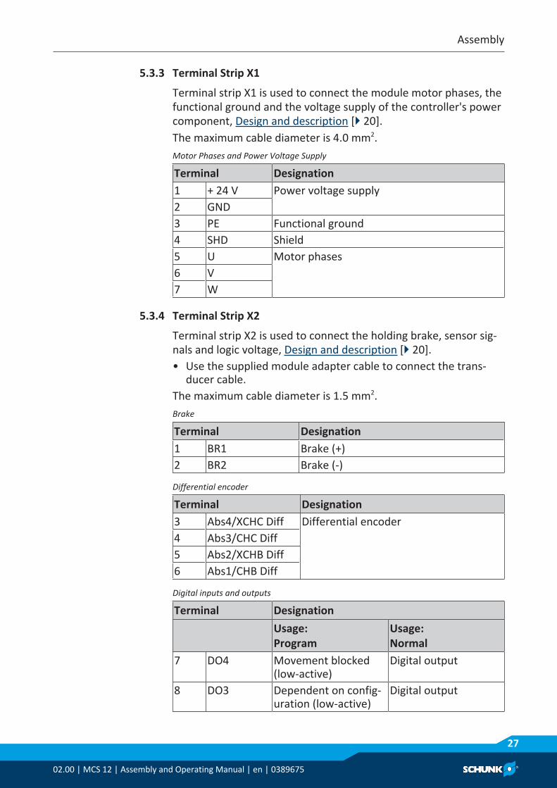
5.3.3 Terminal Strip X1
Terminal strip X1 is used to connect the module motor phases, thefunctional ground and the voltage supply of the controller's powercomponent, Design and description [} 20].The maximum cable diameter is 4.0 mm2.Motor Phases and Power Voltage Supply
Terminal Designation1 + 24 V Power voltage supply2 GND3 PE Functional ground4 SHD Shield5 U Motor phases6 V7 W
5.3.4 Terminal Strip X2
Terminal strip X2 is used to connect the holding brake, sensor sig-nals and logic voltage, Design and description [} 20].• Use the supplied module adapter cable to connect the trans-
ducer cable.The maximum cable diameter is 1.5 mm2.Brake
Terminal Designation1 BR1 Brake (+)2 BR2 Brake (-)
Differential encoder
Terminal Designation3 Abs4/XCHC Diff Differential encoder4 Abs3/CHC Diff5 Abs2/XCHB Diff6 Abs1/CHB Diff
Digital inputs and outputs
Terminal DesignationUsage: Program
Usage: Normal
7 DO4 Movement blocked(low-active)
Digital output
8 DO3 Dependent on config-uration (low-active)
Digital output

Assembly
2802.00 | MCS 12 | Assembly and Operating Manual | en | 0389675
Terminal DesignationUsage: Program
Usage: Normal
9 DO2 Error message (low-active)
Digital output
10 DO1 Referenced (low-active)
Digital output
11 DI4 Program block selection
Digital input (IN3)
12 DI3 Program block selection
Digital input (IN2)
13 DI2 Program block selection
Digital input (IN1)
14 DI1 Enable/external reference switch (firmware version 1.20or higher)
Digital input (IN0)
Logic voltage
Terminal Designation15 GND Reference potential – logic voltage supply16 +24 V Logic voltage supply

Assembly
02.00 | MCS 12 | Assembly and Operating Manual | en | 0389675
29
5.3.5 Terminal Strip X3
Terminal strip X3 is used to connect sensor signals, resolvers andsingle ended, Design and description [} 20].• Use the supplied module adapter cable to connect the trans-
ducer cable.The maximum cable diameter is 1.5 mm2.Differential Encoder and Single Ended
Terminal Designation1 CHA/
XCHA DiffTerminals 1 and 2 have two connections each.Differential encoder: terminals 1 and 2Single ended: terminals 1, 2 and 32 CHZ/
CHA Diff3 CHB
Resolver
Terminal Wire color (*) Designation4 OSZ+ White / Red + Ref5 COS+ Black + Cos5 COS- Red - Cos7 SIN+ Yellow + Sin8 SIN- Blue - Sin9 GND White / Yellow - Ref(*) Wire color of the supplied SCHUNK cable, otherwise accordingto customer specifications
Hall-effect sensors
Terminal Designation10 +5 V Hall-effect sensors11 HC12 XHC13 HB14 XHB15 HA16 XHA

Assembly
3002.00 | MCS 12 | Assembly and Operating Manual | en | 0389675
5.3.6 Communication Interfaces
The controller has the following three communication interfaces:• Fieldbus interface
– CAN bus– Profibus DP
• Parameterization interface– RS232
NOTEThe characteristics of interface RS232 make it unsuitable for useas a fieldbus interface.Only use interface RS232 as the parameterization interface.
The controller can be controlled via these interfaces using theSCHUNK Motion Protocol (SMP).All communication interfaces may be connected simultaneously.However, only one communication interface may be active at anyone time.Depending on the field bus system, up to 255 modules can be con-nected to each other. It is recommended to use T connectors thatcorrespond to the field bus type in order to achieve this. A termin-ation resistor must be set on the last bus node.
RS232 connection The connection is established using a 9-pin SUB-D connector fromthe control unit (PC/PLC) to the controller.
Connector assignment for RS232
Item Description1 Control unit (PC/PLC)2 9-pin SUB-D connector3 9-pin SUB-D socket on the controller
CAN connection The connection is established using a 9-pin SUB-D socket from thecontrol unit (master) to the controller.

Assembly
02.00 | MCS 12 | Assembly and Operating Manual | en | 0389675
31
Socket assignment for CAN bus
Item Description1 Control unit (master)2 9-pin SUB-D socket3 9-pin SUB-D connector on the controller
Profibus DP connection
The connection is established using a 9-pin SUB-D connector fromthe control unit (master) to the controller.
Connector assignment for Profibus DP
Item Description1 Control unit (master)2 9-pin SUB-D connector3 9-pin SUB-D socket on the controller
Digital inputs andoutputs
As an alternative to the field bus, the MCS 12 controller can becontrolled via the digital inputs and outputs, see the Motion Con-trol document.

Functional description
3202.00 | MCS 12 | Assembly and Operating Manual | en | 0389675
6 Functional description6.1 Display Elements
NOTEFor more information on display elements, see the Motion Controldocument.
A green LED POW LED is used as the status display for the motorvoltage. If the LED does not light up, or only lights up very weakly,then the 24 V or 48 V DC ERS motor supply voltage must bechecked.The RDY and ERR LEDs light up for various events in different oper-ating modes. The most important events are given in the followingtable.
RDY and ERR LEDs
OperatingMode
Event RDY LED (green)
ERR LED (red)
Control mode Ready for oper-ation
On Off
Error Off FlashingFirmware update
Downloadingfirmware
On On
Miscellaneous Hardware is notrecognized
Flashing (in alternationwith ERR LED)
Flashing (in alternationwith RDY LED)
Functional description
02.00 | MCS 12 | Assembly and Operating Manual | en | 0389675
33
6.2 Restoring the Factory Settings (DEFAULT Function)
NOTEFor more information on the DEFAULT function and the DEFAULT values, see the Motion Control document.
The DEFAULT function resets the module to its factory settings.Ø Turn off the logic voltage supply on the controller.Ø Set the jumper between pin 6 (GND) and pin 8 (default) on the
CAN bus connector.Ø Turn on the logic voltage supply on the controller.Ø Wait for approx. 10 seconds.Ø Turn off the logic voltage supply on the controller.Ø Remove the jumper between pin 6 (GND) and pin 8 (default).✔ The module is now reset to its factory settings.
DEFAULT Values• Module address = 11
– Controller for drives (ERS)• Module address = 12
– Controller for grippers (EGN/EZN/EVG)• Communication = RS232• Data rate = 9,600 kBaud

Functional description
3402.00 | MCS 12 | Assembly and Operating Manual | en | 0389675
6.3 Writing Firmware (BOOT Function)
NOTEFor more information on the BOOT function, see the Motion Con-trol document.
The BOOT function is used to write the module firmware.
NOTICEThe module will cease to function if all the steps are not com-pleted!• This procedure must not be interrupted.
Ø Turn off the logic voltage supply on the controller.Ø Set the jumper between pin 6 (GND) and pin 1 (boot) on the
CAN bus connector.Ø Turn on the logic voltage supply on the controller.✓ The module is in BOOT mode.
Ø Flash the module with the Motion Tool Schunk software, see theMotion Control document.
Ø Turn off the logic voltage supply on the controller.Ø Remove the jumper between pin 6 (GND) and pin 1 (boot).✔ The firmware has been written.

Start-up and System Integration
02.00 | MCS 12 | Assembly and Operating Manual | en | 0389675
35
7 Start-up and System Integration7.1 Compatibility
The Motion Tool Schunk (MTS) configuration and start-up tool andthe Schunk Motion Protocol (SMP) firmware are not backwardcompatible. This means that the version of MTS that is used mustalways be equal to or higher than the SMP version.If the version of MTS is higher than that of SMP, the module mayend up in an undefined status during parameterization.
Example SMP firmware 1.55 1.56 1.56MTS 1.56.x 1.56.x 1.50.xCompatibility OK OK NOK
The version of the Motion Tool Schunk (MTS) program that is cur-rently in use is shown at the top of the program window.The software version can be found under the General Informationtab, under Software Version.The firmware version currently in use can be found in the modulewindow under Module -> Module Information.
7.2 Configuration with the Motion Tool Schunk (MTS)
NOTEFor more information on configuration using the Motion ToolSchunk, see the Motion Control document.
The module is shipped pre-configured for a fixed fieldbus inter-face, CAN bus or Profibus, Communication Interfaces [} 30]. TheRS232 serial interface is used to parameterize and test the mod-ule.The status of the module must be observed when accessing it viathe RS232 serial interface.The module has two possible states:• The module is in its delivered state [} 35]• The module has been reset to its DEFAULT values [} 40]
7.2.1 The Module is in its Delivered State
If the module is in its delivered state and has an active error, e.g.Motor voltage low, start by performing the following steps. An act-ive error is indicated by a flashing ERR LED.If the ERR LED is not flashing when the machine is in its deliveredstate, the module's bus connection can be broken temporarily totrigger an active error, for example.

Start-up and System Integration
3602.00 | MCS 12 | Assembly and Operating Manual | en | 0389675
Launching MTS ■ ERR LED flashes red■ The controller is connected to a PC■ Motion Tool Schunk (MTS) is installed on the PC
Ø Double-click on the mts.exe icon.✓ Motion Tool Schunk (MTS) will launch.✓ The program window is displayed.
Selecting the RS232interface
Ø Go to Settings -> Open communication….✓ The Open communication window appears.
Ø Under Type, select Serial Generic and press the Select button.✓ The Open communication window closes.
✓ The program window is displayed.

Start-up and System Integration
02.00 | MCS 12 | Assembly and Operating Manual | en | 0389675
37
Searching for themodule
■ Module displays an error, ERR LED flashes red
Ø Go to Module -> Find diagnosis….✓ The Find diagnosis window appears and the system starts to
search for connected modules.
✓ Once the search is complete, the find diagnosis windowcloses and the module window appears.NOTICE! Once the modules have been detected, you canalso press OK to close the window.
Changing the commu-nication mode
Ø NOTICE! The module window opens automatically when afault is detected in the Schunk electronic system.Click on the Parameters tab.

Start-up and System Integration
3802.00 | MCS 12 | Assembly and Operating Manual | en | 0389675
✓ The Parameters tab opens.
Ø Under Communication mode, switch from Profibus to Serial andpress the Write button.✓ The Restart window appears.
Ø Press OK✓ The Restart window closes.✓ Communication with the module is interrupted.

Start-up and System Integration
02.00 | MCS 12 | Assembly and Operating Manual | en | 0389675
39
✓ The program window appears with the message Module re-moved.
Ø Close Motion Tool Schunk (MTS).
NOTEIn order to parameterize the module and test its handling, it hasbeen reset to its DEFAULT values, The module has been reset toits DEFAULT values [} 40].

Start-up and System Integration
4002.00 | MCS 12 | Assembly and Operating Manual | en | 0389675
7.2.2 The module has been reset to its DEFAULT values
Once the module has been reset to its DEFAULT values, Restoringthe Factory Settings (DEFAULT Function) [} 33], perform these ac-tions to parameterize and test the module using the RS232 inter-face.
Launching MTS ■ The controller is connected to a PC■ Motion Tool Schunk (MTS) is installed on the PC
Ø Double-click on the mts.exe icon.✓ Motion Tool Schunk (MTS) will launch.✓ The program window is displayed.
Selecting the RS232interface
Ø Go to Settings -> Open communication….✓ The Open communication window appears.
Ø Under Type, select Serial Generic and press the Select button.✓ The Open communication window closes.

Start-up and System Integration
02.00 | MCS 12 | Assembly and Operating Manual | en | 0389675
41
✓ The program and module windows appear.WARNING! If the module window does not open automatic-ally, a search must be performed to find the module.
Searching for themodule
Ø Go to Module -> Search bus.✓ The Search bus window appears and the system starts to
search for connected modules.
✓ Once the search is complete, the find diagnosis windowcloses and the module window appears.NOTICE! Once the module has been detected, you can alsopress OK to close the window.
Entering parameters NOTEThe module can now be parameterized and tested, see the Helpfunction in the program window or the Motion Control document.

Start-up and System Integration
4202.00 | MCS 12 | Assembly and Operating Manual | en | 0389675
Ø Click on the Parameters tab.✓ The Parameters tab opens.
Ø Enter the parameters and press the Write button.✓ The new values will be adopted into EEPROM.
Ø Click on the Status tab.✓ The Status tab opens.

Start-up and System Integration
02.00 | MCS 12 | Assembly and Operating Manual | en | 0389675
43
Performing a refer-ence run
■ The module has no errors, the Error status bit lights up white
Ø If the Error status bit lights up red: Press the Acknowledge error button.✓ The error is acknowledged and the Error status bit lights up
white.
Ø Press Reference.✓ A reference run will be carried out.

Start-up and System Integration
4402.00 | MCS 12 | Assembly and Operating Manual | en | 0389675
Selecting movementmodes
■ The module has no errors, the Error status bit lights up white■ The module is referenced; the Referenced and Position reached
status bits turn green
Ø Press Movement.✓ The Velocity, Position, Position time, Rel. position, Rel. posi-
tion time, Gripper tabs are displayed.
Ø Click on the tab you required and enter your preferred targetvalues in the input fields.
NOTEA password is required to change the control, referencing anddevice parameters; see the Motion Control document.

Start-up and System Integration
02.00 | MCS 12 | Assembly and Operating Manual | en | 0389675
45
Exiting settings Ø Press Quick stop.
✓ All movement stops.✓ The module displays an error; the Error status bit lights up
red.
Ø Set the fieldbus communication to Profibus or CAN bus andpress Write.✓ The new values will be adopted into EEPROM.

Start-up and System Integration
4602.00 | MCS 12 | Assembly and Operating Manual | en | 0389675
✓ Serial communication with the module is interrupted and themessage MCS 12 not connected appears.
7.3 Start-up
WARNINGRisk of injury due to unexpected movements of the machine/automated system!• Secure the danger zone with suitable protective devices, e.g.
protective fencing, and wear personal protective equipment.
NOTEThe controller is parameterized at the factory for the module thatis to be connected.
Ø Switch on the logic voltage.Ø Switch on the motor voltage.Ø Check whether motor voltage is present (POW LED must light
up green).Ø Adjust the Baud rate if necessary; see the Motion Control docu-
ment.Ø Set the fieldbus address; see the Motion Control document.Ø Check whether the controller can communicate with the master
(RDY LED lights up green).Ø Make sure there are no pending error messages (ERR LED
should not be flashing).Ø If no error message is pending, the controller is ready for opera-
tion.Ø If an error message is pending, Trouble shooting [} 49].

Start-up and System Integration
02.00 | MCS 12 | Assembly and Operating Manual | en | 0389675
47
7.4 Start-up of the Digital Inputs
NOTEFor more information on starting up the digital inputs, see theMotion Control document.
7.5 Start-up of the Digital Outputs
NOTEFor more information on starting up the digital outputs, see theMotion Control document.
7.6 System Integration
7.6.1 SCHUNK Motion protocol
Schunk Motion Protocol
The data frame of the Motion protocol always includes the follow-ing elements:• D-Len (1 byte)• Command code (1 byte)D-Len (Data Length) specifies the number of subsequent items ofuser data including the command byte. The data frame consists ofone byte, therefore a Motion protocol message can transfer amaximum of 255 data bytes.The D-Len byte is always followed by the command code, consist-ing of one byte. If necessary, the command code is followed by therelevant parameters that are required. If required, a "master com-mand" can be extended with a "sub-command".All commands sent are immediately confirmed by the product witha response (acknowledge). This response also uses the data framedescribed above (D-Len, command code, any parameters). If therequest has been processed successfully, D-Len always has a valuethat is not equal to "0x02". If the request fails, D-Len will have thevalue "0x02".
NOTEFor specific features of the different bus systems, please consultthe software manual Motion control.

Start-up and System Integration
4802.00 | MCS 12 | Assembly and Operating Manual | en | 0389675
7.6.2 System Structure
Control unit (master)
PLC/PC
Module 1 Module 2 Module 3
(...)
(...)
Controller 1 Controller 3Controller 2
Fieldbus
Data format The data is transferred in Intel (little Endian) format.
NOTEThe numbers of connected products depends on which bus isused. A maximum of 255 IDs can be assigned: see the document"motion Control".

Trouble shooting
02.00 | MCS 12 | Assembly and Operating Manual | en | 0389675
49
8 Trouble shootingAfter an error with error message has been resolved, this errormessage has to be acknowledged, see document Motion Control.The error is indicated via the (red) LED ERR.A list of the info and error codes is contained in the document Mo-tion Control. A detailed error information may be read out via Motion ToolSchunk (MTS), see document Motion Control.
8.1 LEDs on Controller Do Not Light UpPossible cause Corrective actionNo voltage connected. Check the power and logic voltage supplies
on the controller.Master (control unit) on the field bus is notactive.
Check the master; reactivate fieldbus com-munication if necessary.
8.2 RDY LED (Green) Does Not Light UpPossible cause Corrective actionLogic voltage supply missing. Check logic voltage supply on terminal X2.Faulty connection. Check all connections.
8.3 LED POW (green) doesn't light up or is only slightlyilluminated
Possible cause Corrective actionThere is no or too little power voltage. Check power supply on terminal X1.
8.4 LED ERR (red) lights up and LED RDY (green) doesn't
NOTETroubleshooting, see document Motion Control.

Trouble shooting
5002.00 | MCS 12 | Assembly and Operating Manual | en | 0389675
8.5 Communication failurePossible cause Corrective actionFuse logic supply triggered Check fuse logic supply, replace it if neces-
sary.Connection between Controller and MotionTool Schunk (MTS) has been interrupted.
Check bus cable or cable for interface RS232for damage, replace it if necessary.
No establishment of communication pos-sible withMotion Tool Schunk (MTS)(Interface RS232, Profibus or CAN-bus)
Check delivery status NOTICE! The controller is delivered in thecommunication mode Profibus.Check communication interface, Link MotionTool Schunk starten.Check closing termination, Is module final station connected to thebus?Is a termination resistor necessary?Module with CAN-BusCheck and adjust address of the CAN-Bus,see document Motion Control.Check baud rate, Link Baudrate.Module with ProfibusCheck GSD-file, use convenient GSD-file ifnecessary.Check and adjust address Profibus, see doc-ument Motion Control.Check baud rate, max.l 1.5 MBaud.
Values are safed in the EEPROM but are notactivated.
Before writing stop the module which is con-nected to the controller via quick stop andrestart the module after writing.NOTICE! In the EEPROM the new values arenot adopted, if the module which is connec-ted to the controller is in motion.
Maintenance and care
02.00 | MCS 12 | Assembly and Operating Manual | en | 0389675
51
9 Maintenance and careThe controller is maintenance-free.If the controller gets dirty, wipe it carefully with a soft cloth. Donot use solvents.
NOTEIn case of a defect, send the module to SCHUNK together with arepair order.

Appendix
5202.00 | MCS 12 | Assembly and Operating Manual | en | 0389675
10 Appendix
MCS 12 Connection Diagram - Overview

Appendix
02.00 | MCS 12 | Assembly and Operating Manual | en | 0389675
53
MCS 12 Connection Diagram with EGN/EZN

Appendix
5402.00 | MCS 12 | Assembly and Operating Manual | en | 0389675
MCS 12 Connection Diagram with ERS

Notes
02.00 | MCS 12 | Assembly and Operating Manual | en | 0389675
55
Notes

5602.00 | MCS 12 | Assembly and Operating Manual | en | 0389675