assembly instructions dof reality p3
TRANSCRIPT

Assembly Instructions DOF Reality H6 and P6
1
WARNING! Assembled platform will have exposed motors moving parts. Never operate it with small
children around. Protection cover sold separately. During initial assembly don’t tighten the bolts
completely, do it after everything is assembled. First you need to assemble the full frame and tighten
the screws and bolts after.
Please check all the motor power and sensor plugs. Reconnect them if they happen to have
been disconnected during shipping. This is very important: Never change the wiring. Mixing the colors
to the connectors can damage the motors and platform controllers.
Our platform is very lightweight and simple due to its perfect weight balance. This allows us to
use affordable motors and gearboxes. If you plan to put something besides standard wheel, pedals,
yoke, gear shifter, throttle and HOTAS you need to plan and install it properly. Each additional element
(even if it is light weight) connected to the moving platform should be well positioned and
counterbalanced. Even a light-weight screen/monitor placed on our simulator can cause problems. It is
always better to consult us first, before installing any extra equipment on the platform.
Don’t put ANY controllers on the platform before it is completely tested and proven to be
working as desired. After assembly attach the seat only; nothing extra. After you ensure that the
simulator is moving appropriately, you can start adding controllers one by one, doing movement tests
with the a person seated in the chair. This will replicate the weight distribution.
Each platform control box is shipped preset to the voltage of the destination country. If you
are not sure about the proper voltage settings, turn it upside-down and check ALL 2 or 3 red switches
inside the box and consult us.
If you not sure what bolts to use print the following 1:1 template on corresponding paper size without
extra borders or spacing:
For US Letter Paper : https://dofreality.com/hardware_template_Letter.pdf
For A4 Paper : https://dofreality.com/hardware_templateA4.pdf
Never ever leave platform powered unattended and powered on when not used. Motors are constantly doing micro adjustments. When overheated over 70C they can loose the power.

Assembly Instructions DOF Reality H6 and P6
2
If you doing upgrade from 3 or 2 DOF pls review https://dofreality.com/instructionsUHP6.pdf
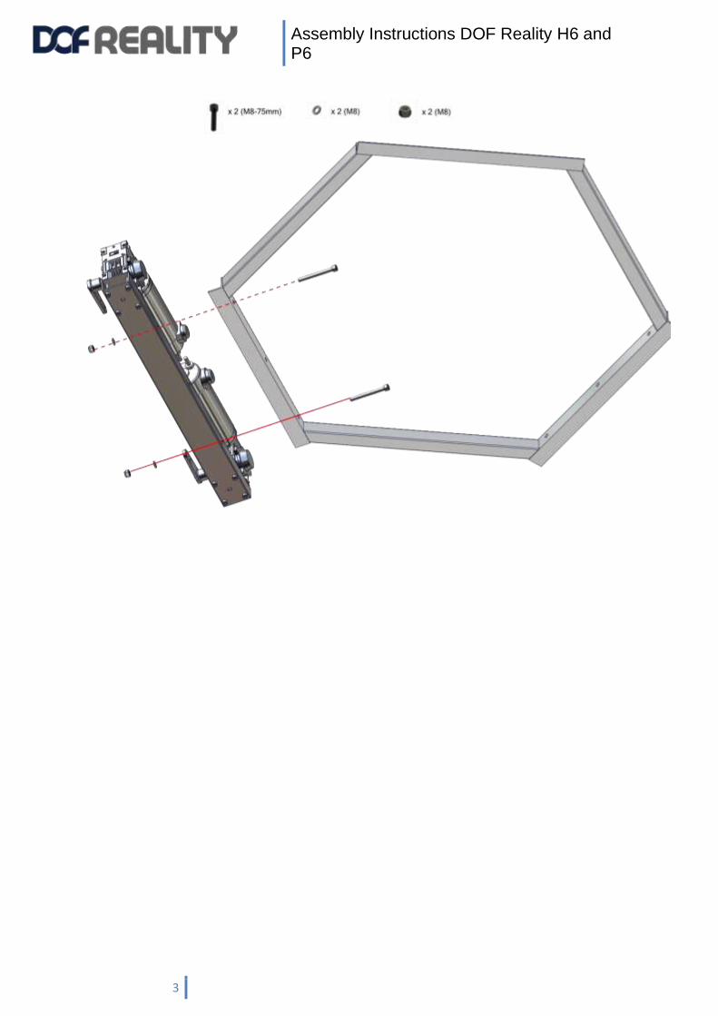
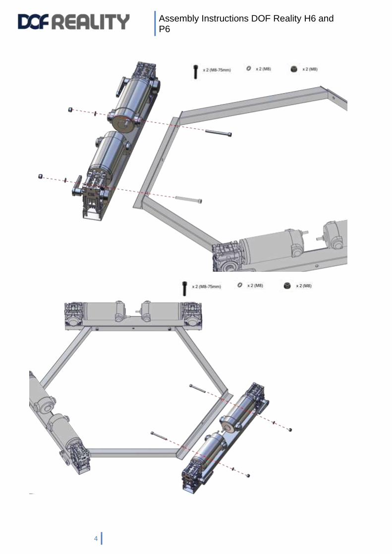
1 . Step by step assembly instructions:
Never ever leave platform powered unattended and powered on when not used. Motors are constantly doing micro adjustments. When overheated over 70C they can loose the power.
Attach motors to the hex base with M8х75 (6 pcs.)
Make sure all motors are attached according to the labeled by numbers, and the black motor
arms are facing the motor itself as shown below in the hexagon:
Assembly Instructions DOF Reality H6 and P6
3
Assembly Instructions DOF Reality H6 and P6
4
Assembly Instructions DOF Reality H6 and P6
5
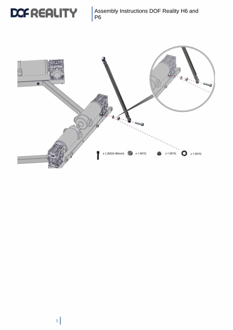
x 1 (M10-40mm)

Assembly Instructions DOF Reality H6 and P6
6
x 1 (M10-40mm)
Assembly Instructions DOF Reality H6 and P6
7

Assembly Instructions DOF Reality H6 and P6
8
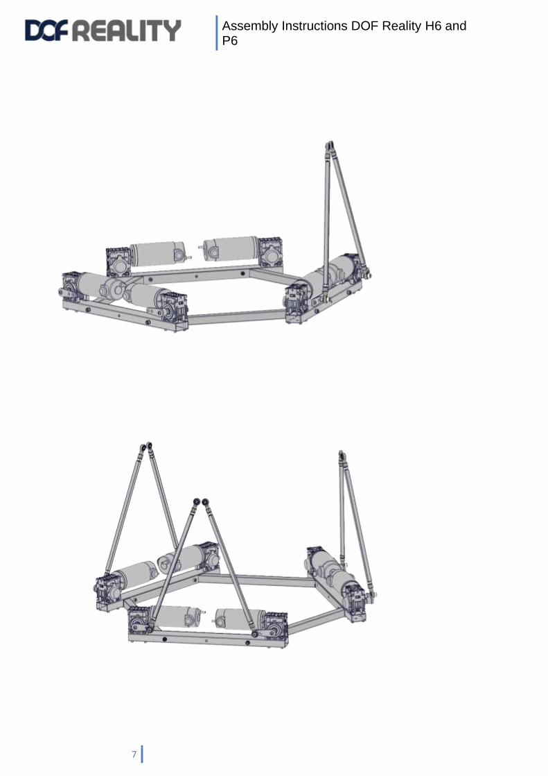
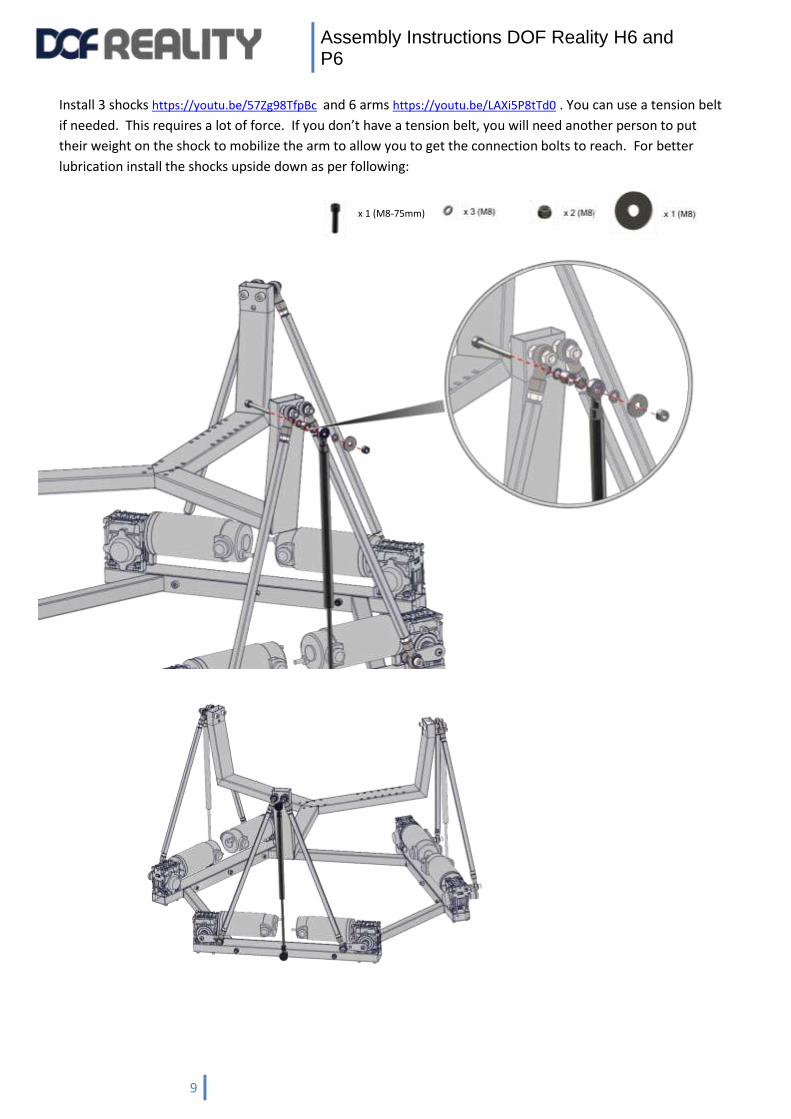
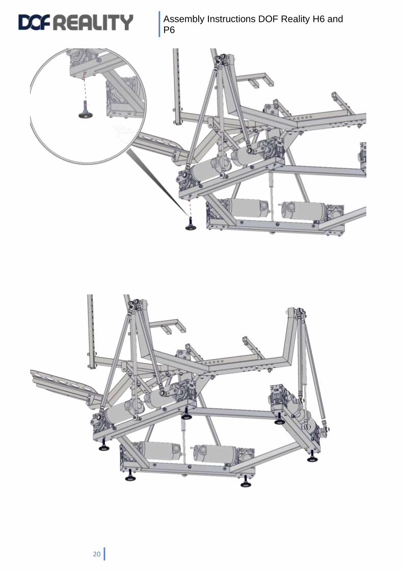
Shocks can be hard to compress. You can change the following steps order: 1) attach 3 shocks to the bottom
of the hexagon frame 2) attach tristar crib to shocks only 3) using your own weight to the tristar crib
compress them one by one and attrach 6 arms.
x 6 (M10-65mm)
Assembly Instructions DOF Reality H6 and P6
9
Install 3 shocks https://youtu.be/57Zg98TfpBc and 6 arms https://youtu.be/LAXi5P8tTd0 . You can use a tension belt
if needed. This requires a lot of force. If you don’t have a tension belt, you will need another person to put
their weight on the shock to mobilize the arm to allow you to get the connection bolts to reach. For better
lubrication install the shocks upside down as per following:
x 1 (M8-75mm)

Assembly Instructions DOF Reality H6 and P6
10
x 2 (M8-65mm)
Assembly Instructions DOF Reality H6 and P6
11
Assembly Instructions DOF Reality H6 and P6
12
x 1 (M8-70mm)
Assembly Instructions DOF Reality H6 and P6
13
x 1 (M8-70mm)

Assembly Instructions DOF Reality H6 and P6
14
Assembly Instructions DOF Reality H6 and P6
15
Assembly Instructions DOF Reality H6 and P6
16
Assembly Instructions DOF Reality H6 and P6
17

Assembly Instructions DOF Reality H6 and P6
18

Assembly Instructions DOF Reality H6 and P6
19
Assembly Instructions DOF Reality H6 and P6
20
Assembly Instructions DOF Reality H6 and P6
21
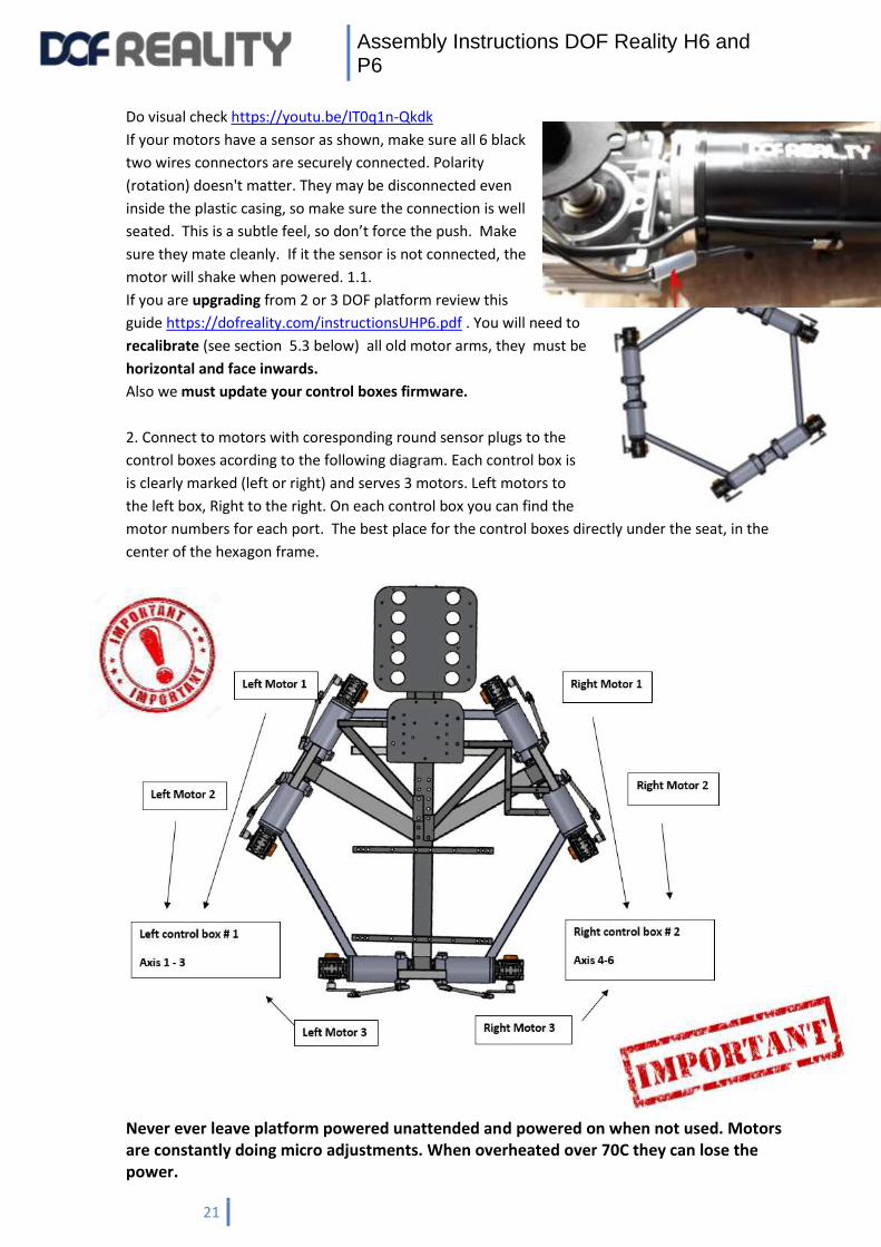
Do visual check https://youtu.be/IT0q1n-Qkdk
If your motors have a sensor as shown, make sure all 6 black
two wires connectors are securely connected. Polarity
(rotation) doesn't matter. They may be disconnected even
inside the plastic casing, so make sure the connection is well
seated. This is a subtle feel, so don’t force the push. Make
sure they mate cleanly. If it the sensor is not connected, the
motor will shake when powered. 1.1.
If you are upgrading from 2 or 3 DOF platform review this
guide https://dofreality.com/instructionsUHP6.pdf . You will need to
recalibrate (see section 5.3 below) all old motor arms, they must be
horizontal and face inwards.
Also we must update your control boxes firmware.
2. Connect to motors with coresponding round sensor plugs to the
control boxes acording to the following diagram. Each control box is
is clearly marked (left or right) and serves 3 motors. Left motors to
the left box, Right to the right. On each control box you can find the
motor numbers for each port. The best place for the control boxes directly under the seat, in the
center of the hexagon frame.
Never ever leave platform powered unattended and powered on when not used. Motors are constantly doing micro adjustments. When overheated over 70C they can lose the power.
Assembly Instructions DOF Reality H6 and P6
22
For US and 110-120 volt power supply countries you must use two different power cords (each
plugged into a separate outlet), one for each control box! Each line current can only handle 15 Amp
and peak power consumption of the two combined boxes can be more than your breaker can handle,
resulting in the breaker to fail, if this happens you will have to reset your breaker to this part of the
house.
2.2 BALANCING – This is a critical step to get the best performance and lifespan from your platform!
When all is moving and working, and you have mounted all your game controllers on the platform,
try to make sure the extra weight is balanced over the platform around the Center Of Gravity
under the center of the platform. If you add weight on one side (e.g. front right) the opposite
side (rear left) must be loaded with more weight in order to counterbalance.
0) If your platform was delivered on or before 2020, we will need to update your firmware with “firmware
updater.exe” . it is inside https://dofreality.com/tools.zip
1) you close SRS and disable PC Bluetooth before starting it.
Unzip and run balancing app for your model from https://dofreality.com/tools.zip
2) click Connect and when connected you should see two ports in the boxes under the buttons
3) wait 10 sec and click Balance . get inside your seat after 10 sec delay (to let you get into the seat etc) you
will hear ding sound and your platform will move up and down. When done you will hear another ding sound.
During motions app might be unresponsive.
4) you will see recommendations on the screen WHERE to move weight and the number telling how much to
move. the number is not in pounds or kilos, but rather relative units.
5) you move your body only to the mentioned direction. temporary , just to see the results. It might be
inconvenient to stay this way , but we just testing it now. and click Balance again .
6) platform will move and give you new results ON THE TOP of the old ones.
7) when you get perfect or almost perfect balancing position move the seat and other objects on your platform
and retest it with your normal sitting position until your get balancing done.
We strongly advise against adding weight in this fashion, as this adds unnecessary weight for the motors to lift
while changing directions. The best counter-balance is your own weight, which is governed by the seat position.
If one or multiple motors are overheating (or even getting hot) during use this is might mean that one side of
the platform is overloaded and you need to move some structural weight away from that side. The motors
should NEVER be hot! Overheated magnets inside the motor loose power forever and it leads to substantial
motor power decrease.
Assembly Instructions DOF Reality H6 and P6
23
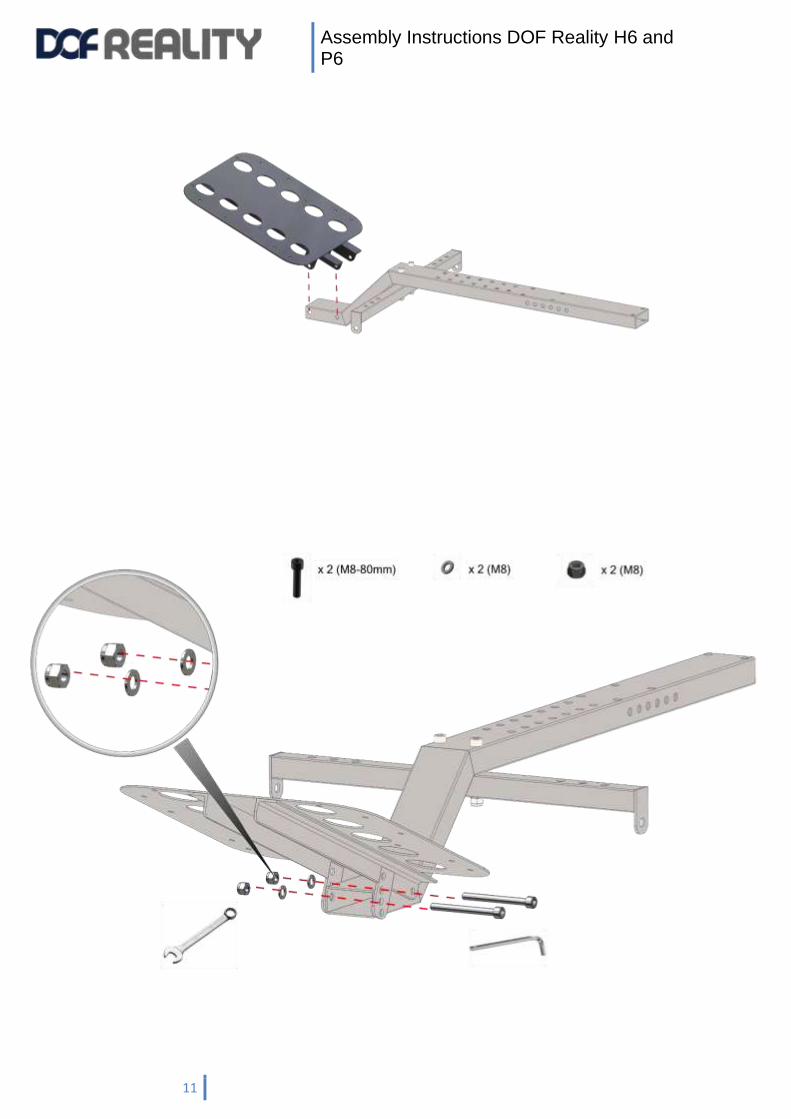
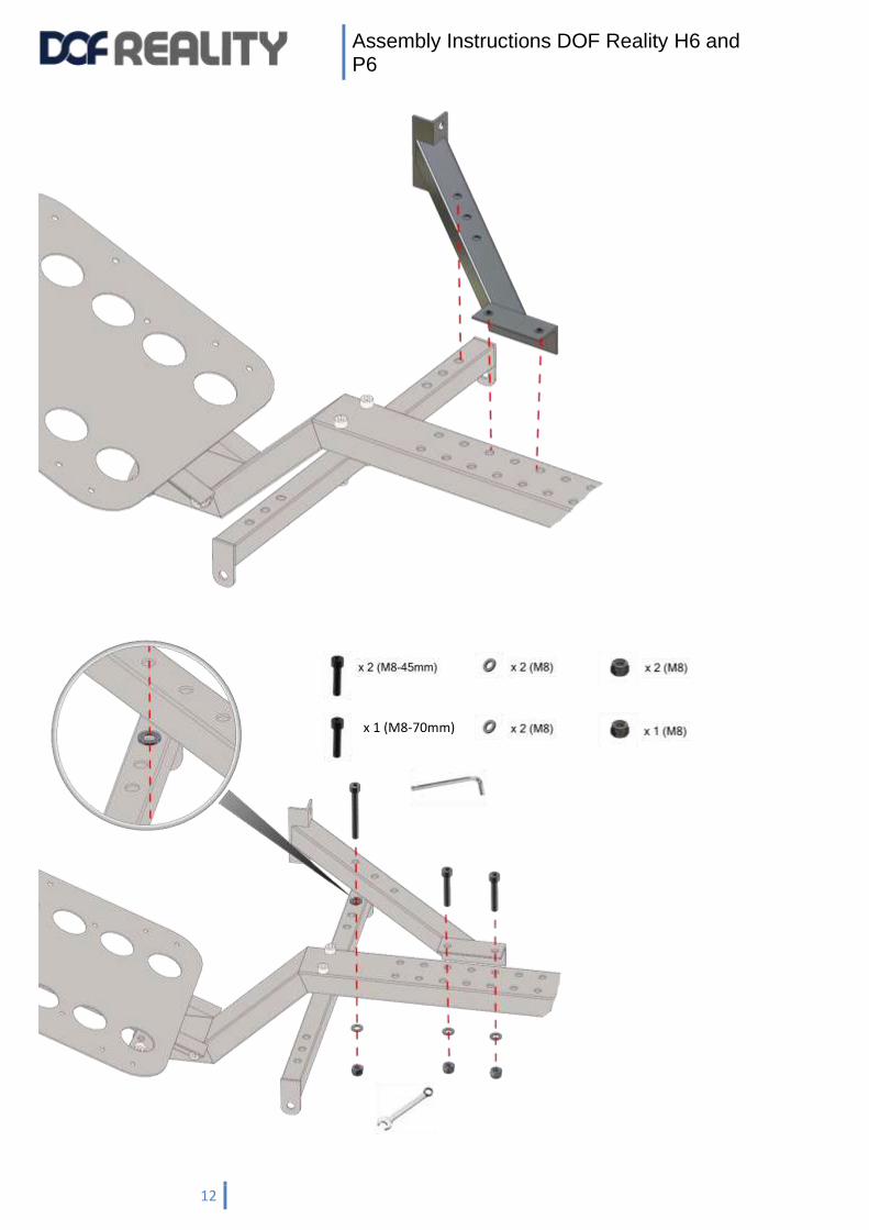
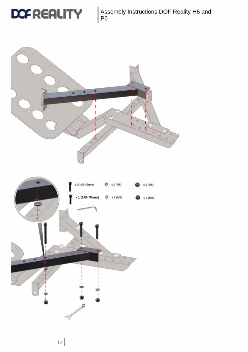
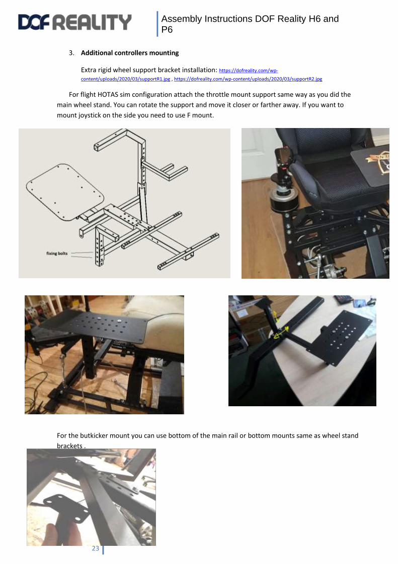
3. Additional controllers mounting
Extra rigid wheel support bracket installation: https://dofreality.com/wp-
content/uploads/2020/03/supportR1.jpg , https://dofreality.com/wp-content/uploads/2020/03/supportR2.jpg
For flight HOTAS sim configuration attach the throttle mount support same way as you did the
main wheel stand. You can rotate the support and move it closer or farther away. If you want to
mount joystick on the side you need to use F mount.
For the butkicker mount you can use bottom of the main rail or bottom mounts same as wheel stand
brackets .
Assembly Instructions DOF Reality H6 and P6
24
4. Software installation
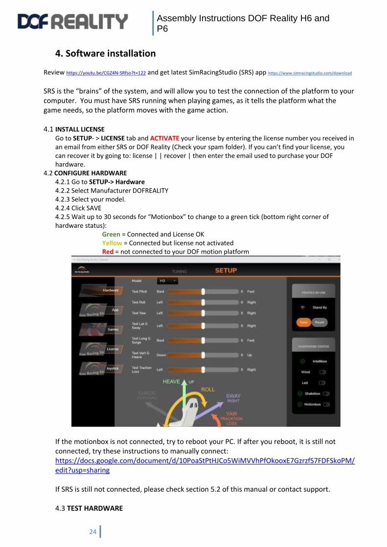
Review https://youtu.be/CGZ4N-SRfso?t=122 and get latest SimRacingStudio (SRS) app https://www.simracingstudio.com/download SRS is the “brains” of the system, and will allow you to test the connection of the platform to your computer. You must have SRS running when playing games, as it tells the platform what the game needs, so the platform moves with the game action. 4.1 INSTALL LICENSE
Go to SETUP- > LICENSE tab and ACTIVATE your license by entering the license number you received in an email from either SRS or DOF Reality (Check your spam folder). If you can’t find your license, you can recover it by going to: license | | recover | then enter the email used to purchase your DOF hardware.
4.2 CONFIGURE HARDWARE 4.2.1 Go to SETUP-> Hardware 4.2.2 Select Manufacturer DOFREALITY 4.2.3 Select your model. 4.2.4 Click SAVE 4.2.5 Wait up to 30 seconds for “Motionbox” to change to a green tick (bottom right corner of hardware status):
Green = Connected and License OK Yellow = Connected but license not activated Red = not connected to your DOF motion platform
If the motionbox is not connected, try to reboot your PC. If after you reboot, it is still not connected, try these instructions to manually connect: https://docs.google.com/document/d/10PoaStPtHJCo5WiMVVhPfOkooxE7GzrzfS7FDFSkoPM/edit?usp=sharing If SRS is still not connected, please check section 5.2 of this manual or contact support.
4.3 TEST HARDWARE

Assembly Instructions DOF Reality H6 and P6
25
Once connected, use your mouse to move TEST sliders and see if platform is moving and in the correct direction.
Assembly Instructions DOF Reality H6 and P6
26
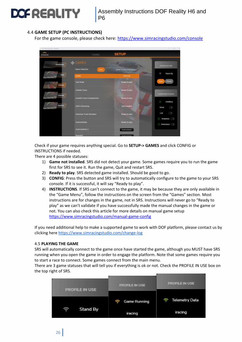
4.4 GAME SETUP (PC INSTRUCTIONS) For the game console, please check here: https://www.simracingstudio.com/console
Check if your game requires anything special. Go to SETUP-> GAMES and click CONFIG or INSTRUCTIONS if needed. There are 4 possible statuses:
1) Game not installed. SRS did not detect your game. Some games require you to run the game first for SRS to see it. Run the game, Quit and restart SRS.
2) Ready to play. SRS detected game installed. Should be good to go. 3) CONFIG: Press the button and SRS will try to automatically configure to the game to your SRS
console. If it is successful, it will say “Ready to play”. 4) INSTRUCTIONS. If SRS can’t connect to the game, it may be because they are only available in
the “Game Menu”, follow the instructions on the screen from the “Games” section. Most instructions are for changes in the game, not in SRS. Instructions will never go to “Ready to play” as we can’t validate if you have successfully made the manual changes in the game or not. You can also check this article for more details on manual game setup https://www.simracingstudio.com/manual-game-config
If you need additional help to make a supported game to work with DOF platform, please contact us by clicking here https://www.simracingstudio.com/change-log 4.5 PLAYING THE GAME SRS will automatically connect to the game once have started the game, although you MUST have SRS running when you open the game in order to engage the platform. Note that some games require you to start a race to connect. Some games connect from the main menu. There are 3 game statuses that will tell you if everything is ok or not. Check the PROFILE IN USE box on the top right of SRS.
Assembly Instructions DOF Reality H6 and P6
27
1) STAND BY: Game not running 2) GAME RUNNING: Game is detected…no telemetry to move platform has yet been received.
For Some games, this is NORMAL as they only send telemetry once you are on the track or in the air…
a. In this status, you also unlocked the TUNING -> MOTION settings. Now you can make changes to the tuning parameters (See below).
3) TELEMETRY DATA: All good. If the MOTIONBOX status is green and SRS is in this status, the
platform will be moving for this game. Make sure platform boxes are ON…😊 a. Intellibox is for Wind (if you didn’t buy the wind accessory, you won’t have this), Led
and Tach are used if you bought an LED or Tachometer as a separate accessory for your racing system. Shakebox is for the buttkicker.
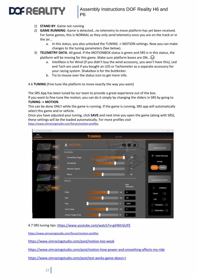
b. Try to mouse over the status icon to get more info. 4.6 TUNING (Fine tune the platform to move exactly the way you want) The SRS App has been tuned by our team to provide a great experience out of the box. If you want to fine-tune the motion, you can do it simply by changing the sliders in SRS by going to TUNING -> MOTION. This can be done ONLY while the game is running. If the game is running, SRS app will automatically select this game and or vehicle. Once you have adjusted your tuning, click SAVE and next time you open the game (along with SRS), these settings will be the loaded automatically. For more profiles visit https://www.simracingstudio.com/forum/motion-profiles
4.7 SRS tuning tips: https://www.youtube.com/watch?v=giHMrIjiUFE
https://www.simracingstudio.com/forum/motion-profiles
https://www.simracingstudio.com/post/motion-too-weak
https://www.simracingstudio.com/post/motion-how-power-and-smoothing-affects-my-ride
https://www.simracingstudio.com/post/test-works-game-doesn-t

Assembly Instructions DOF Reality H6 and P6
28
You can also find additional help in our FAQ. https://www.simracingstudio.com/copy-of-download-faq-1
4.8 VR (Virtual Reality)
The DOF motion platform can be used with any VR headset. There are some subtleties to be considered when
combining VR with a motion platform. The motion platform will move the player’s head, which will move the VR
headset, which will automatically affect the amount of movement you see in the VR image. Most of the time, the
degree of motion is not enough to impact gameplay and can be ignored like in this example video
https://youtu.be/oi8yvWzZXVw. If the additional motion of the VR image is too extreme, you might need to turn down
the motion of the platform to a lower setting. This will minimize the “hopping/swimming” type of effects in the image
and will give you a smoother experience with VR.
Software Solution for Motion Compensation
If the amount of movement in the VR image is too much and you do not want to turn down the motion, you can utilize
motion compensation software which removes the platform movement from the VR image. You have few options:
1) The best way is to use SimRacingStudio Motion compensation premium feature https://www.simracingstudio.com/post/motion-
compensation 2) OpenVR Motion Compensation is the current software to be utilized for motion compensation which can be
downloaded here: https://ovrmc.dschadu.de/. OpenVR Motion Compensation will track the movement of a
tracker mounted on the platform and remove the motion of the platform from the movement of the VR
headset. OpenVR Motion Compensation can work with both types of VR headsets (base stations and inside-out
tracking).
OpenVR Motion Compensation Tutorial Video: https://www.youtube.com/watch?v=1MqGO46xdtI&t
OpenVR Motion Compensation Install and Setup: https://ovrmc.dschadu.de/en/setup
There are primarily two types of VR headsets and they require the tracker to be mounted differently. Ones
that utilize base stations (outside-in) for tracking of the VR headset movements such as the Valve Index, HTC
Vive Cosmos, Pimax 5k/8k* and the original Oculus Rift (CV1). The other type utilizes cameras in the headsets
that provide inside-out tracking which include the HP Reverb/G2, Oculus Quest/Quest 2/Rift S**, Samsung
HMD Odyssey+ and other Windows Mix Reality (WMR) type headsets.
For VR headsets that utilize base stations, a tracker or controller (Valve Index Controller, HTC Vive Controller,
HTC Vive Tracker) must be mounted on the motion platform and be in-line of sight by all the base stations. It
does not matter where the tracker is mounted as long as its visible to all the base stations, though typically
they are mounted near the head at the top of the chair.
For VR headsets that utilize inside-out tracking via the cameras on the headset, a controller (Oculus Touch
Controller or WMR Controller) must be mounted on the front of the motion platform so it is in-line of sight of
the cameras on the headset.
In either case, the tracker must be 1) firmly mounted to the platform and 2) must utilize some type of vibration
mitigation. Vibration mitigation can be achieved by 1) adding additional mass/weight to the mount so it
absorbs vibration energy and 2) using a vibration absorption material like soft rubber or Sorbothane.
Assembly Instructions DOF Reality H6 and P6
29
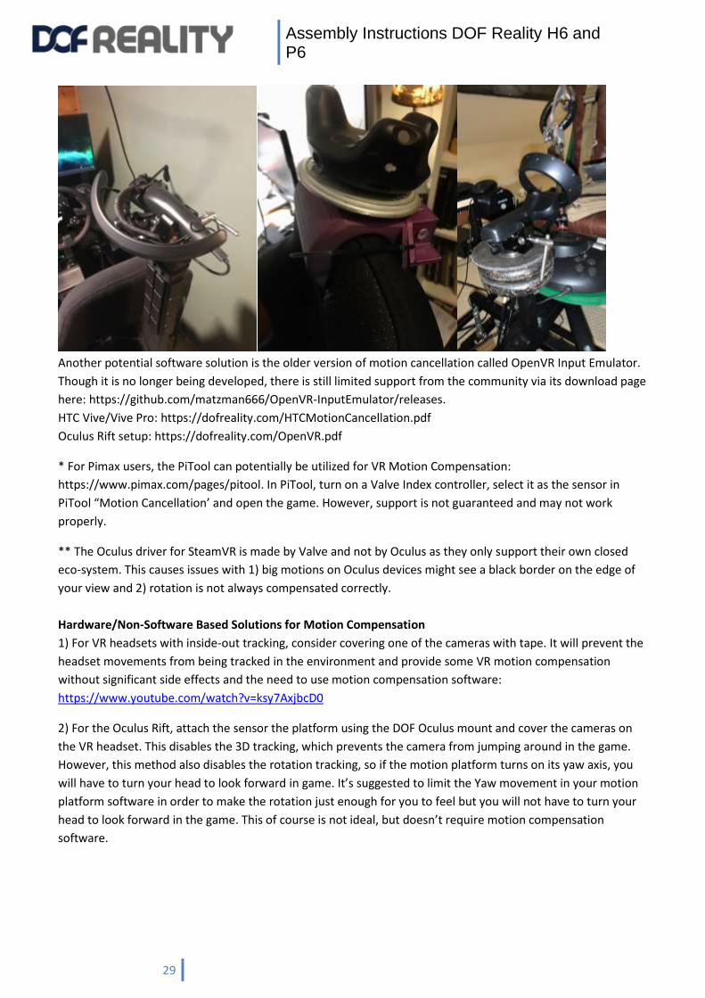
Another potential software solution is the older version of motion cancellation called OpenVR Input Emulator.
Though it is no longer being developed, there is still limited support from the community via its download page
here: https://github.com/matzman666/OpenVR-InputEmulator/releases.
HTC Vive/Vive Pro: https://dofreality.com/HTCMotionCancellation.pdf
Oculus Rift setup: https://dofreality.com/OpenVR.pdf
* For Pimax users, the PiTool can potentially be utilized for VR Motion Compensation:
https://www.pimax.com/pages/pitool. In PiTool, turn on a Valve Index controller, select it as the sensor in
PiTool “Motion Cancellation’ and open the game. However, support is not guaranteed and may not work
properly.
** The Oculus driver for SteamVR is made by Valve and not by Oculus as they only support their own closed
eco-system. This causes issues with 1) big motions on Oculus devices might see a black border on the edge of
your view and 2) rotation is not always compensated correctly.
Hardware/Non-Software Based Solutions for Motion Compensation
1) For VR headsets with inside-out tracking, consider covering one of the cameras with tape. It will prevent the
headset movements from being tracked in the environment and provide some VR motion compensation
without significant side effects and the need to use motion compensation software:
https://www.youtube.com/watch?v=ksy7AxjbcD0
2) For the Oculus Rift, attach the sensor the platform using the DOF Oculus mount and cover the cameras on
the VR headset. This disables the 3D tracking, which prevents the camera from jumping around in the game.
However, this method also disables the rotation tracking, so if the motion platform turns on its yaw axis, you
will have to turn your head to look forward in game. It’s suggested to limit the Yaw movement in your motion
platform software in order to make the rotation just enough for you to feel but you will not have to turn your
head to look forward in the game. This of course is not ideal, but doesn’t require motion compensation
software.

Assembly Instructions DOF Reality H6 and P6
30
3) For original Oculus Rift (CV1) users, the Oculus Rift sensor could be mounted directly to your DOF Reality
platform to provide simulated motion compensation without the need to use motion compensation software;
however, due to recent Oculus update this solution may or may not work. DOF Reality includes a mount for the
Oculus Rift sensor in your DOF hardware shipment which should be placed at the front of the platform looking
back at the VR headset. Mount the bracket to the two holes at the back of the wheel deck plate so it extends
up and out to the front of the platform.
Additional VR Motion Compensation Resources
OpenVR Motion Compensation Tested Devices: https://ovrmc.dschadu.de/en/testeddevices
XSimulator Motion Compensation Thread: https://www.xsimulator.net/community/threads/openvr-
motioncompensation.14576/
XSimulator Motion Cancellation Thread: https://www.xsimulator.net/community/threads/vr-motion-
cancellation-time-to-test.10241/
HTC Vive Tracker Mount Example: https://www.youtube.com/watch?v=BPmo5kmk5CY
Assembly Instructions DOF Reality H6 and P6
31
5. Troubleshooting & Maintenance
The simulator does not need much maintenance, but you should check for loose bolts or other
abnormalities periodically (we recommend once a month).
- Confirm the security of the nuts and bolts every few weeks.
- Listen for any abnormal noises, if encountered please follow the instructions below on how to
grease the ball joints attached to the motor arms.
5.1 Platform doesn’t move and is not shown as “Connected” in SRS.
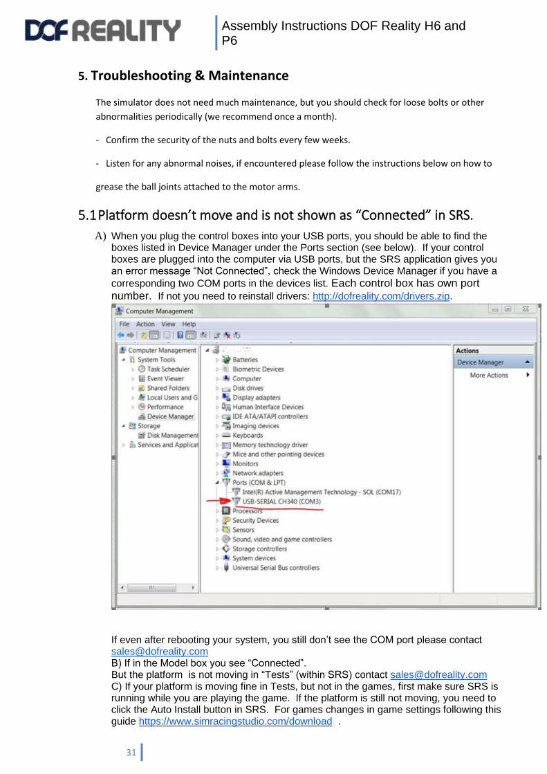
A) When you plug the control boxes into your USB ports, you should be able to find the boxes listed in Device Manager under the Ports section (see below). If your control boxes are plugged into the computer via USB ports, but the SRS application gives you an error message “Not Connected”, check the Windows Device Manager if you have a
corresponding two COM ports in the devices list. Each control box has own port number. If not you need to reinstall drivers: http://dofreality.com/drivers.zip.
If even after rebooting your system, you still don’t see the COM port please contact [email protected] B) If in the Model box you see “Connected”. But the platform is not moving in “Tests” (within SRS) contact [email protected] C) If your platform is moving fine in Tests, but not in the games, first make sure SRS is running while you are playing the game. If the platform is still not moving, you need to click the Auto Install button in SRS. For games changes in game settings following this guide https://www.simracingstudio.com/download .

Assembly Instructions DOF Reality H6 and P6
32
If the platform still doesn’t move, you should pen a ticket by emailing [email protected].
5.2 If one or more of your motors are stuck in an improper position and
don’t seem to respond
If a motor gets into the “protection zone”, it may stop responding. If this occurs, the mechanical
position is so far out of line that the software locks. To unlock it:
1) Power off both control boxes
2) Close all SRS applications
3) Download http://dofreality.com/SMC3Utils.zip
4) Unzip all archive contents into any local folder on your PC
5) Open with notepad file SMC3Utils.ini and set COMM_PORT= to proper COM port number
from your Windows Device Manager (see 5.1) Each control box has a specific port number.
Test one box at a time.
6) Start/run SMC3Utils.exe. If you are getting an error messages about the COM port
communication, you haven’t set the port number properly in the previous step.
7) Select the problematic motor . Most commonly, in the SRS application, the motor will be
shown as OFF and the green line on the chart for it is below the blue line. Disconnect
corresponding motor vertical silver links from the black motor arm so motor black arm can
rotate freely 360 degree.
8) Write down current Max Limits and Clip Input values (on the right of the SMC3Utils window)
and reduce them to 0. Normal is Max Limit 50, and Clip Input is 190.
9) In SMC3Utils click small OFF button in the top left hand part of the screen, so it becomes
ON. Select the button next to the motor you are adjusting. If you can’t set motor to ON, zero
all other motors Clip Input and Max Limit to unlock it as one motor locks all.
10) Power ON the platform
11) The motor should move back to normal position. If you want to check the motion, you can
select the 'Sine' radio buttonand see that it moves appropriately. The green line is a
reflection of the measured motor position (where it actually is), the blue line is the desired
motor position (where it theoretically should be). These will not be perfectly aligned, but
should be similar. 2) If the motor arm has recalibrated, reset the original Max Limits and Clip
Input values (you need to increase Clip first and then Max as max can’t be bigger than Clip) and
close SMC3Utils.
5.3 Motor arm is not horizontal in the neutral position
The resting position of the black motor arm should be:

Assembly Instructions DOF Reality H6 and P6
33
If your motor arm is out of the natural/level position it should be reset. Correct calibration is
the default resting arm position of the motor. Setting this correctly fixes several problems
commonly experienced by users. To recalibrate the motor arm, you will need the small “allen
wrench” or “hex key” provided in your hardware kit.
Over time the motor-sensor coupler bolts may get loose and the neutral motor position can get
malaligned from normal (often the arm moves just a bit higher than horizontal). If this is the case
perform tests (see section 5.4) to make sure motor is moving correctly first or consult DOF Reality
support.
Please review the video of the calibration procedure: https://www.youtube.com/watch?v=Wa6hRdMB4vA
1. Before starting, fully exit everything else on the PC possible, especially SimRacingStudio and
SimHub (check the Windows task manager to make sure).
2. Download http://dofreality.com/SMC3Utils.zip, unzip all contents into any local folder on
your PC. Open with notepad file SMC3Utils.ini and set COMM_PORT= to proper COM port
number from your Windows Device Manager (see 5.1). If you have H6/P6 DOF: each control
box has a specific port number. In order for SRS find the control box, you must know which
box corresponds to the desired control box. See section 5.2.4.Run SMC3Utils.exe. If you are
getting an error messages about COM port communication, you haven’t set port the number
properly in this step.
3. Make sure the DOFR control box power is OFF (make sure motor connections and the USB
remain fully plugged in).
4. Using a wrench and the large allen wrench, disconnect the silver threaded “motor arm”
from the motor that needs to be re-calibrated. Disconnect only from motor side and leave
hanging freely. If you have a damper attached, you will need to disconnect that as well. The
motor needs to be free to move.
5. On the side of the motor pointing towards the center of the platform, use a small allen
wrench to loosen the “coupler” (silver tube like roller). You only want to loosen the two small
allen screws on the MOTOR SIDE. The other side is the “sensor” that connects to the plastic
cover. Do not touch the sensor side allen screws.
6. On your PC go to the SMC3 application.
7. With a computer screen-shot (or your phone) take a picture of the SMC3 screen with the
current settings and values (IMPORTANT). The default settings are: Fpid / 10, Kp = 120, Ki = 1,
Kd = 10, Ks = 5, PWMmin = 0, PWMmax = 180, PWMrev =200, Max limit = 50, Clip Input =
190, Deadzone = 0.
8. At top left of SMC3 tool now click “ON” the motor that needs calibrated.
9. Click the “step 1” buttons to say “step 10”
10. Click “KP” down to “60”
11. “PWMmax” to “60” and “Ki” to “0” (zero).
12. At this point the “Max Limits” and “Clip Input” should also have adjusted down to 0 as well.
If not, then click them both to “0”.
13. Power ON the DOFR control box.
14. By hand, slowly rotate the “coupler” (silver tube like roller). It will move the green graph
line in the SMC3 tool. Make sure this is happening. If not, start over.
15. Now slowly rotate the coupler until the small black motor arm is leveled to flat horizontal
position (pointing inward to another pair motor).
16. Power OFF the DOFR control box.
Assembly Instructions DOF Reality H6 and P6
34
17. Now looking at the SMC3 program tool, slowly rotate the coupler until the green line sits in
the middle of the graph slightly below the blue line. At this point the green line should be
moving right with the blue line.
18. Now take the allen wrench and without moving the “coupler”, properly tighten ONE of the
allen screws we previously loosened(as you do this make sure green line stays in position on
SMC3 with the blue line).
19. Tighten then the second allen screw.
20. Now in the SMC3 application, turn all values back to original settings(from your earlier
screen-capture or phone picture) The default settings are: Fpid / 10, Kp = 120, Ki = 1, Kd = 10,
Ks = 5, PWMmin = 0, PWMmax = 180, PWMrev =200, Max limit = 50, Clip Input = 190,
Deadzone = 0
21. Power on the control box.
22. On the SMC3 tool at the bottom left area, click “Sine”.
23. If we have been successful the green and blue line on the SMC3 will start moving up and
down almost together with the black motor arm we just re-calibrated.
24. Exit SMC3 tool and you are ready to go. If this is not fixing your problem, please review and
repeat these steps very carefully. If you are still not able to recalibrate the motor arm to a
horizontal position, contact DOF Reality.
Assembly Instructions DOF Reality H6 and P6
35
5.4 Something is wrong with my platform!
1) Check all cables and motor connections, including any loose wires inside the control box.
2) Close and exit SimRacingStudio.
3) Download http://dofreality.com/SMC3Utils.zip
4) Unzip all contents into any local folder on your PC.
5) Open SMC3Utils.ini with notepad and set COMM_PORT= to the proper COM port number
from your Windows Device Manager (see 5.1) . Each control box should have a specific port
number. Test one box at a time.
6) Start/run SMC3Utils.exe. If you are getting an error message regarding the COM port
communication, you haven’t set the port number properly in the previous steps.
7) Power ON the platform
8) Set it to 'sine' click Motor 1 and Motor 2 and 3 send us ([email protected]) screen shots
of the SMC Util charts for each motor. It will also be helpful to include a short video clearly
demonstrating the problem. If motor is not moving smooth, shaking and green line don’t
follow blue this is completely normal. In 6 DOF motors cant move independent (one at a time)
when they interconnected to the frame .
5.5 I have troubles installing SRS (Antivirus detects it as a threat)
SRS uses a variety of methods to read the telemetry from the game and some of those
methods will trigger antivirus software. SRS is completely safe, use your antivirus software to
allow an exception for SRS. This will typically solve the problem.
5.6 Simulator does not move in-game
Make sure the SRS application is open and running in the background. This connects the simulator to your gaming software. If you have already confirmed this, click the “Auto Install” button from within the SRS Game section. For some games, you will need to the game settings following this guide: https://www.simracingstudio.com/download. If you have completed all this, and your platform still doesn’t move, please Open a Ticket by contacting [email protected].
5.7 Simulator used to work in the game, but stopped
This can happen if the connection is lost to the computer or Windows Defender (or other
antivirus software) have deemed the software a threat. Windows Defender is notorious for
this. Please investigate with your antivirus software. Usually an SRS reinstall helps or you can
add an exception for SRS from within your antivirus software application.
5.8 The motors make small adjustments all the time
This is because the motors always have power flowing through them, and are always in a ready
state to be able to move the rig quickly without delay. The small movements of the motors will
typically disappear when there is weight on the rig or it is in use.

Assembly Instructions DOF Reality H6 and P6
36
5.9 The simulator behaves strangely while playing games
There are many reasons you may experience this behavior, but the most common reasons are: - The simulator is not in balance. - The simulator doesn’t have the right settings for you. (We supply generic settings, but they might not match your preferences, weight distribution, or accessory setup). - The rig might be too heavy.
5.10 Platform sometimes shakes while in motion The platform is not a precise scientific tool and designed for amusement purposes. SRS -> Setup -> Motion test sliders motions can't be used to test platform coordination and smoothness. Moving the sliders with the mouse or keyboard won't do proper coordinated commands to the platform to judge the smoothness. In order to do proper testing: 1) check that all 6 motors black arms are at the same level when at natural position: Remove all rods and shock absorbers, set the angles of all black arms on the motors exactly the same level according to instructions in chapter 5.3 2) unzip this file to a new folder https://dofreality.com/HeaveTest.zip 3) run RunTest.bat. if you don’t have running numbers in the black window check error messages with a link in it. You might need to download MS .Net 3.5. and run RunTest.bat again until you see running numbers . 4) set following tuning settings in SRS https://dofreality.com/wp-content/uploads/2020/11/teststune1.png
https://dofreality.com/wp-content/uploads/2020/11/teststune2.png
5) make sure you are sitting in the sim and weight is about balanced and center of weight is in the center of the platform. You can experiment with moving your body around the crib. 6) Make a video filmed from the side of the platform with this test and someone in the seat so we can clearly see all 6 motors moving in pairs. https://www.youtube.com/watch?v=l8RRoI1uMIE and email it to [email protected]
6 Repairing the simulator
The simulator should under no circumstances be repaired by unauthorized personnel without
consulting DOF Reality first. Failing to comply may cause damage to equipment and/or injury.
7 Technical Specifications
Motion Simulator for computer gaming
Brand: DOF Reality
Model: DOF REALITY H6/P6
Power input: 100-120/210-240VAC, 50/60Hz
Power consumption: 2400Watt
Peak current: 20.0/10.9A
Short-circuit rating: 60A (30A for each control box)
IP number: 1P190305.DR0W93
Total Weight: 87.300 kg
Made in Ukraine by: “DOF REALITY” LLC
Zaporizhzhya, Harchova, 17/94, Ukraine, 69014
EN 60204-1:2006/AC:2010, EN 60335-2-82:2003/A1:2008, EN 60335-1:2012+A11:2014; EN
55014-1:2006+A1:2009+A2:2011; EN 61000-3-2:2014; EN 61000-3-3:2013. 2019
http://dofreality.com/CE.pdf