ASSEMBLY & OPERATION MANUAL - Sweatband...multi-gym to protect wood flooring or carpeting from damage during assembly and usage. This multi-gym is intended for indoor use only. Rust
30
ASSEMBLY & OPERATION MANUAL RECORD SERIAL NUMBER HERE www.inspirefitness.net by Health In Motion LLC Feb. 2012
CONGRATULATIONS… You’ve just taken the first step to a healthier and stronger body. This multi-gym by Inspire offers the key to unlocking your body’s potential. Regular strength training on a multi-gym has been shown to deliver a host of benefits including: increased muscle tone, decreased body fat, improved energy levels, a reduction in stress, and improved cardiac output. Once again, congratulations, you are on your way to improving your self image, overall health, and quality of life. BEFORE ASSEMBLING YOUR HOME GYM IMPORTANT: Read this entire manual before attempting to build or use this machine. This manual contains step by step instructions for proper assembly. Use the parts list included in this manual to verify that all parts are accounted for before assembly. If any parts are missing, contact the retailer of this multi-gym for replacement parts. Or, call Inspire at 877-738-1729. Make sure that adequate room has been cleared before attempting to build your multi-gym. A rubber mat is recommended for use under your multi-gym to protect wood flooring or carpeting from damage during assembly and usage. This multi-gym is intended for indoor use only. Rust can form on certain parts including guide rods in a humid environment, resulting in impaired function. Service of your multi-gym should only be preformed by an authorized Inspire retailer. Service preformed by anyone else can result in loss of warranty. If you need help finding an authorized retailer, please contact us directly: Inspire Fitness 4945 East Hunter Avenue Anaheim, CA 92807 Ph: 877-738-1729 Fx: 714-738-1728 www.inspirefitness.net
TABLE OF CONTENTS Section Description……………………………………………………. Page Important Safety Instructions………………………………………. 1 Tools Required………………………………………………………………… 1 Parts List………………………………….................…………………. 2 Cable Chart ……………………………………………………………………. 3 Assembly Instructions……………………………………………………. 4-19 Decal Reference……………………………………………………………… 2021 Decal Placement……………………………………………………………… 22 Accessories, Options, Training Tips..……………………………… 23 General Maintenance Information…….…………………………… 24 Maintenance Schedule…….……………………………………………… 25 Limited Warranty…………………………………………………………….. 26
IMPORTANT SAFETY INSTRUCTIONS Please read this entire manual and familiarize yourself with all decals and warnings before using this multi-gym. • WARNING! It is necessary to inspect this multi-gym regularly to maintain safety and proper function. Please use the maintenance schedule included towards the back of this manual. Immediately replace any and all defective or worn parts. Pay special attention to moving parts such as the cables and pulleys and connections to accessories. See General Maintenance section for complete details. • Use this multi-gym for its intended purpose as described in this Operation Manual or the exercise chart. Do not use attachments not recommended by the manufacturer. • Do not hang from press arm. The press arm is not designed to support human weight. • Make sure bystanders are at least 5 feet away from the multi-gym while it is in use. • Keep children off the multi-gym at all times. • Keep the multi-gym away from walls and clear of any obstructions and furniture. • Stop immediately if you experience shortness of breath, pain, or dizziness during your workout. Inspire strongly recommends consulting your doctor before starting an exercise program. TOOLS REQUIRED FOR ASSEMBLY • Metric socket set (including 17mm, 18mm, and 19mm sockets) • Metric 17mm, 18mm, and 19mm wrenches • 6mm, 5mm, 4mm, and 3mm Allen wrenches (supplied in the hardware packs) • Adjustable wrench • Metric Tape Measure • Rubber Mallet
PAGE 1
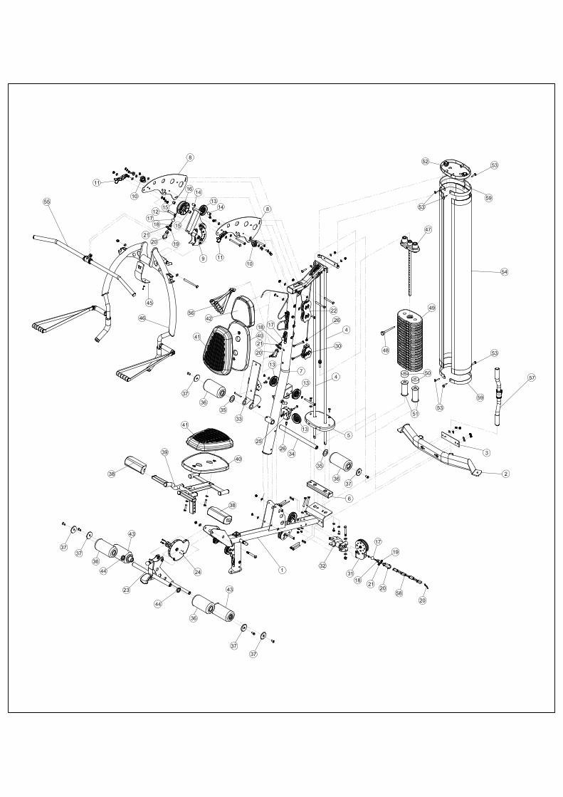
PAGE 2
M2 Parts List Part No EVS CODE Description Q'ty 30 GM872-381-006PZ Adj Floating Pulley Bracket 1
1 GM872-200-001PZ Main Base 1 31 GM872-380-001PZ Swivel Pulley 1
2 GM872-100-001 Rear Base 1 32 GM872-381-001 U Bracket 1
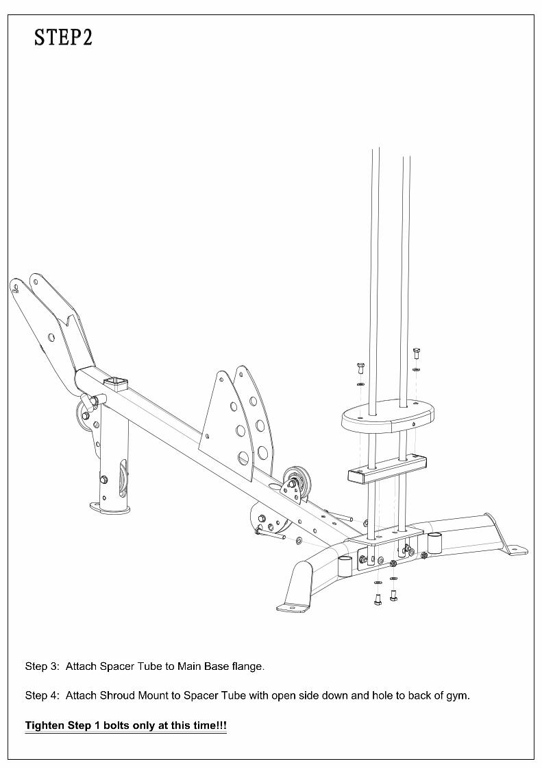
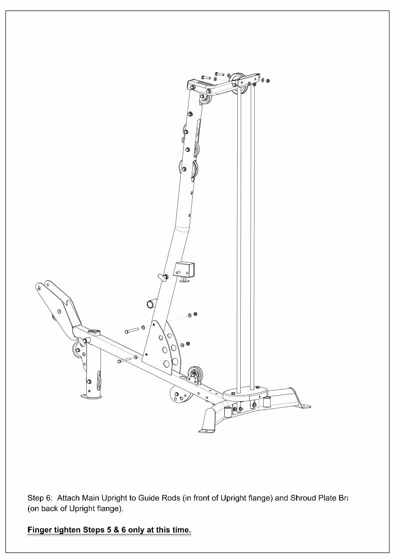
Step 2: Attach Guide Rods to Rear Base. Step 3: Attach Spacer Tube to Main Base flange. Step 4: Attach Shroud Mount to Spacer Tube with open side down and hole to back of gym. Tighten Step 1 bolts only at this time!!!
Step 5: Attach Main Upright to Main Base. Step 6: Attach Main Upright to Guide Rods (in front of Upright flange) and Shroud Plate Bracket (on back of Upright flange). Finger tighten Steps 5 & 6 only at this time.
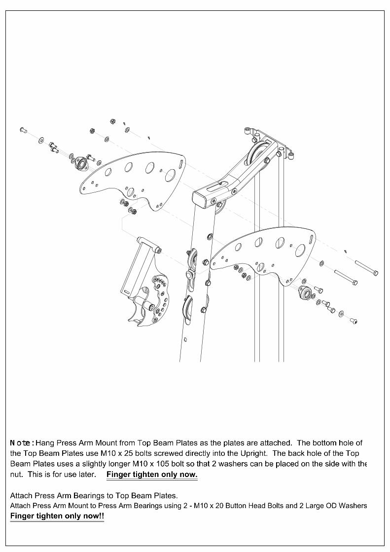
STEP 7: Attach Right and Left Top Beam Plates to the Main Upright (with the INSPIRE logo facing out) as shown. Note: Hang Press Arm Mount from Top Beam Plates as the plates are attached. The bottom hole of the Top Beam Plates use M10 x 25 bolts screwed directly into the Upright. The back hole of the Top Beam Plates uses a slightly longer M10 x 105 bolt so that 2 washers can be placed on the side with the nut. This is for use later.Finger tighten only now. Attach Press Arm Bearings to Top Beam Plates. Attach Press Arm Mount to Press Arm Bearings using 2 - M10 x 20 Button Head Bolts and 2 Large OD Washers. Finger tighten only now!!
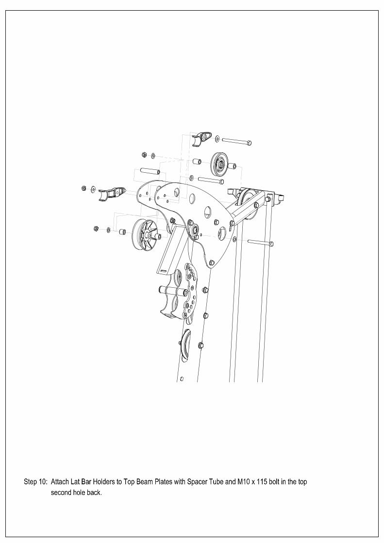
Step 8:Attach Pulley 10 to Top Beam Plates (just behind bearings) with M10 x 100 bolt. Step 9:Attach 4 1/2" Wide Pulley 11 to Top Beam Plates with M10 x 100 bolt in the lowest front hole. Step 10:Attach Lat Bar Holders to Top Beam Plates with Spacer Tube and M10 x 115 bolt in the top second hole back.
Ted Habing
Text Box
Pulley 10
Ted Habing
Text Box
Pulley 11
Ted Habing
Line
Ted Habing
Line
Ted Habing
Text Box
PAGE 8
qxlwl
标注
NOTE: Once Assembled, slide rubber washer against plastic ball
qxlwl
标注
STEP 12 1 – Plastic Ball 1 – Cable “U” Bracket 1 – M6 x 12 Button Head Bolt 1 – Spring Clip 1 – M6 T Nut
qxlwl
标注
NOTE: CABLE GOES INSIDE FRAME TUBE
qxlwl
文本框
PULLEY
qxlwl
文本框
PULLEY
qxlwl
线条
qxlwl
线条
qxlwl
标注
Press Arm Mount
qxlwl
线条
qxlwl
线条
qxlwl
线条
qxlwl
线条
qxlwl
线条
qxlwl
图章
qxlwl
图章
qxlwl
图章
qxlwl
图章
qxlwl
图章
qxlwl
图章
qxlwl
矩形
qxlwl
线条
qxlwl
线条
qxlwl
线条
qxlwl
线条
qxlwl
标注
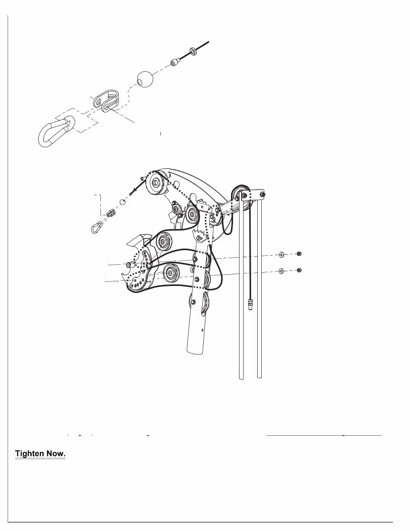
STEP 11
Ted Habing
Text Box
Step 11:Attach Upper Cable. Begin by running Upper Cable from back of machine to front as shown. Weave cable through pulleys and out over the Wide Groove pulley. Step 12: Assemble cable end by sliding the plastic ball onto the end of the cable. Next slide the cable end into the side of the U bracket. Attach Spring Clip to U bracket using Button Head Bolt and T nut as shown. Slide the rubber washer against the ball. Tighten Now.
Ted Habing
Text Box
Leave loop of cable hanging down here!!
Ted Habing
Line
Ted Habing
Text Box
PAGE 9
Ted Habing
Text Box
Hex Head goes on side with the stop flat.
Ted Habing
Text Box
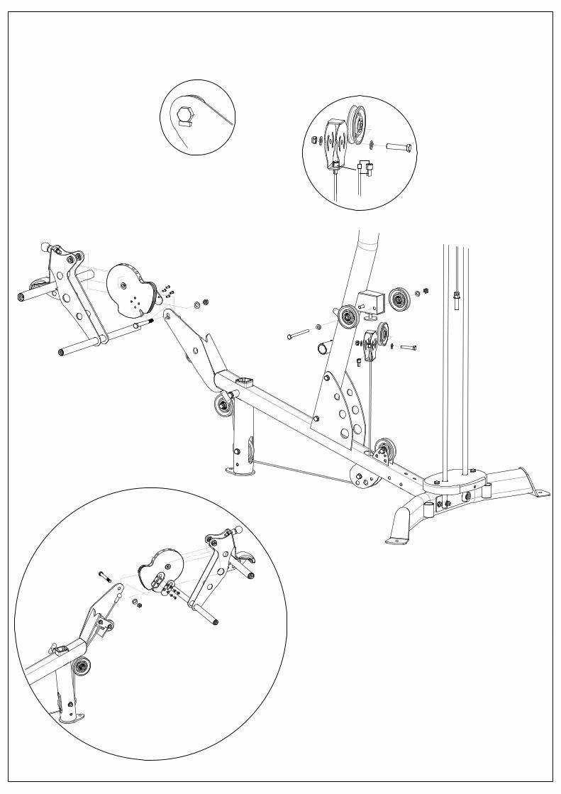
Step 15: Insert L/E cable into hole at bottom of Floating Pulley Bracket. Secure with Cable Adapter and Pulley 19. Tighten Now. Tighten Step 13 Now.
Note: Be sure to feed the L/E Cable between the 2 small pulleys and over the small plate behind the 2 small pulleys, as the L/E and Cam are attached.
Ted Habing
Text Box
Step 13: Attach Pulleys 12 & 13 to Main Upright. Step 14: Remove the 4 Flat Head Cap Screws and Cam Plate from the L/E Cam. Next, using the same 4 Flat Head Screws and the Cam Plate, attach the Leg Extension Cable to the L/E Cam as shown in the circle diagram. Tighten Now! Attach L/E Cam and L/E Assembly to the front of Main Base (Lower Numbers on Cam should be on top). See Note! Tighten Now, Do Not Over Tighten. L/E Assembly should swivel freely. Route L/E cable behind Pulley 3, down to front of & under Pulley 4 (make sure cable is routed between the cable retainer pin and pulley on Pulleys 4 & 2), back under & up around Pulley 2, to Floating Pulley Bracket. Go to Step 15 above.
Ted Habing
Line
Ted Habing
Line
Ted Habing
Line
Ted Habing
Line
Ted Habing
Line
Ted Habing
Line
Ted Habing
Line
Ted Habing
Line
Ted Habing
Line
Ted Habing
Line
Ted Habing
Line
Ted Habing
Line
Ted Habing
Text Box
Pulley 19
Ted Habing
Line
Ted Habing
Line
Ted Habing
Line
Ted Habing
Line
Ted Habing
Text Box
PAGE 10
qxlwl
图章
qxlwl
线条
qxlwl
线条
qxlwl
标注
STEP16 1 – Middle Cable
qxlwl
线条
qxlwl
线条
Ted Habing
Text Box
Floating Pulley Plates
Ted Habing
Line
Ted Habing
Text Box
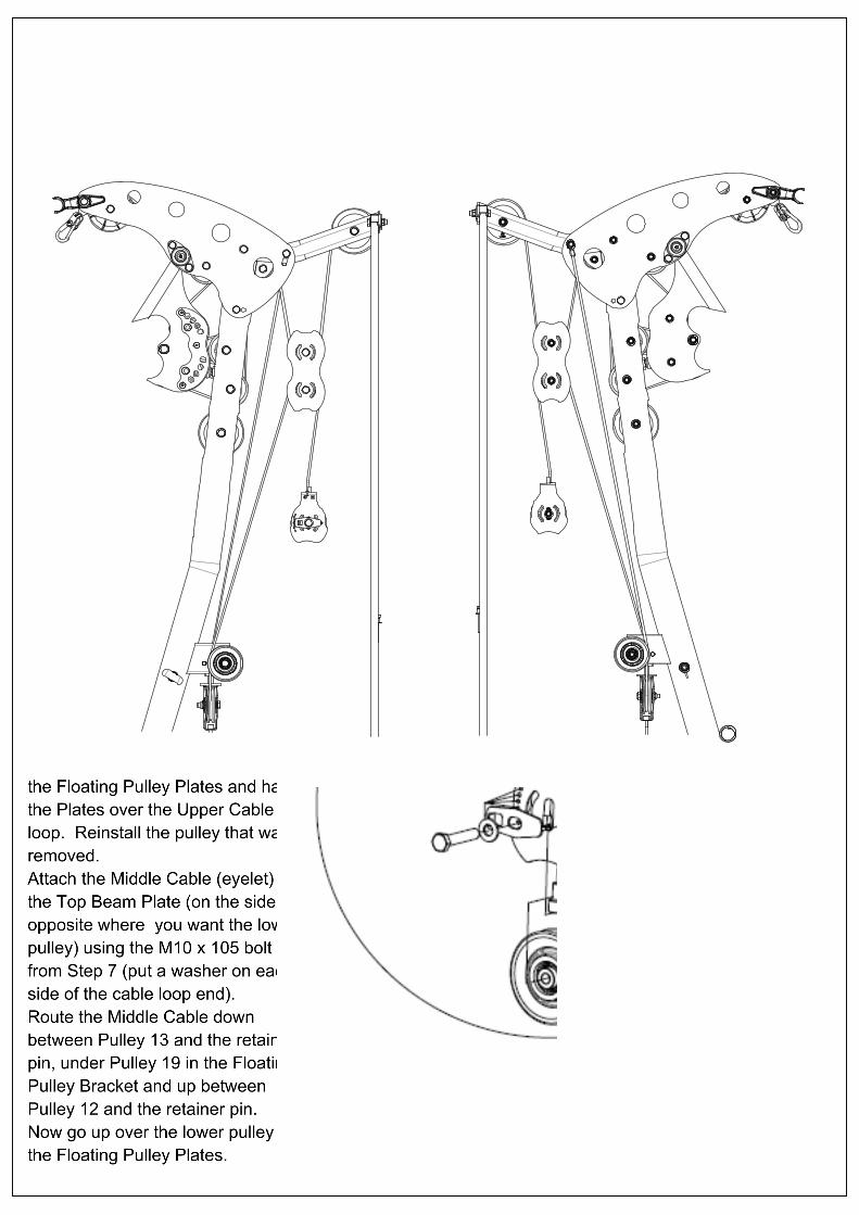
Step 16: Take one pulley out of the Floating Pulley Plates and hang the Plates over the Upper Cable loop. Reinstall the pulley that was removed. Attach the Middle Cable (eyelet) to the Top Beam Plate (on the side opposite where you want the low pulley) using the M10 x 105 bolt from Step 7 (put a washer on each side of the cable loop end). Route the Middle Cable down between Pulley 13 and the retainer pin, under Pulley 19 in the Floating Pulley Bracket and up between Pulley 12 and the retainer pin. Now go up over the lower pulley in the Floating Pulley Plates.
Ted Habing
Text Box
Top Beam
Ted Habing
Line
Ted Habing
Text Box
Pulleys 12 & 13
Ted Habing
Text Box
Pulley 19
Ted Habing
Line
Ted Habing
Line
Ted Habing
Line
Ted Habing
Text Box
Step 16 cont.: Remove the L bracket in the Adjustable Floating Pulley Bracket. Insert the cable end in the Bracket as shown in the circle and place the Cable Adapter on the cable end. Secure with the L bracket. Tighten L bracket now. Tighten Top Beam Bolt with cable end now.
Ted Habing
Text Box
Adjustable Floating Pulley Bracket
Ted Habing
Line
Ted Habing
Line
Ted Habing
Line
Ted Habing
Line
Ted Habing
Line
Ted Habing
Line
Ted Habing
Line
Ted Habing
Text Box
Cable Adapter
Ted Habing
Line
Ted Habing
Text Box
Note: Cable end must be attached to the Top Beam Plate opposite of the side you want the Low Pulley. If you have the Leg Press Option, it will be on the same side as the Leg Press!!
Ted Habing
Text Box
PAGE 11
qxlwl
标注
STEP 19 1 – Plastic Ball 1 – Cable “U” Bracket 1 – M6 x 12 Button Head Bolt 1 – M6 T Nut 1 – Spring Clip
qxlwl
线条
qxlwl
标注
STEP 20 Lower Cable
qxlwl
线条
qxlwl
标注
STEP 21 1 – Plastic Ball 1 – Cable “U” Bracket 1 – M6 x 12 Button Head Bolt 1 – M6 T Nut 1 – Spring Clip
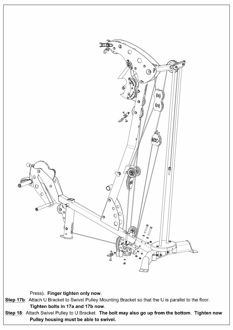
Step 17a: Attach Swivel Pulley Mounting Bracket to Main Base (Opposite side of top cable and Leg Press). Finger tighten only now. Step 17b: Attach U Bracket to Swivel Pulley Mounting Bracket so that the U is parallel to the floor. Tighten bolts in 17a and 17b now. Step 18: Attach Swivel Pulley to U Bracket. The bolt may also go up from the bottom. Tighten now. Pulley housing must be able to swivel.
Ted Habing
Line
Ted Habing
Line
Ted Habing
Line
Ted Habing
Line
Ted Habing
Text Box
Step 19: Assemble one end of the Lower Cable as shown in Step 12. Slide the rubber washer against the ball. Tighten Now. Step 20: Route the other end of the Lower Cable over Pulley 11 (front to back), down (between the two sides of the Middle Cable), under Pulley 1 (front to back) and up to the front side and around the pulley in the Adjustable Pulley Bracket, then down under the Swivel Pulley.
Ted Habing
Text Box
Pulley 11
Ted Habing
Text Box
Pulley 1
Ted Habing
Text Box
Adjustable Pulley Bracket
Ted Habing
Text Box
Swivel Pulley
Ted Habing
Line
Ted Habing
Line
Ted Habing
Line
Ted Habing
Line
Ted Habing
Text Box
Step 21: Assemble the second cable end as shown in Step 12. Make sure the cable is between the pulley and retainer pin in the Swivel Pulley Bracket. Tighten Now.
Ted Habing
Text Box
U Bracket
Ted Habing
Line
Ted Habing
Line
Ted Habing
Line
Ted Habing
Line
Ted Habing
Line
Ted Habing
Text Box
PAGE 12
qxlwl
图章
qxlwl
标注
STEP 24b 2 – M6 x 8 Set screws
qxlwl
线条
qxlwl
标注
Roller Tube Mount
qxlwl
线条
qxlwl
标注
STEP 24a Attach Rollers
qxlwl
线条
qxlwl
标注
STEP 22 Attach Backpad Tilt Frame with Roller Tube.
qxlwl
线条
qxlwl
线条
qxlwl
线条
qxlwl
标注
STEP 23 1 – M6 x 75 Button Head Bolt 1 – M6 T Nut
qxlwl
线条
qxlwl
标注
Main Upright
qxlwl
标注
Backpad Tilt Frame
qxlwl
线条
qxlwl
线条
Ted Habing
Text Box
2 - M10 x 25 Flat Head Screws
Ted Habing
Line
Ted Habing
Text Box
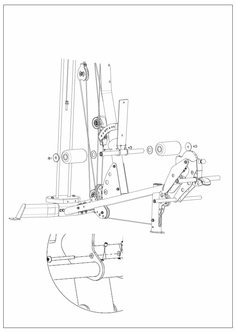
Step 22: Attach Back Pad Tilt Frame to Main Upright with the Roller Tube as shown. Make sure Spring Pin on Main Upright is aligned with one of the middle holes on the selector plate. Step 23: Install Button Head Bolt and T-Nut and tighten so there is slight resistance when tilting Back Pad. Step 24a: Slide Plastic Washers onto Roller Tube, followed by Roller Pads. Secure with Aluminum End Caps and Flat Head Screws. Tighten Now. Step 24b: Secure Roller Tube to Roller Tube Mount with set screws provided. See Circle diagram below. Tighten Now.
Ted Habing
Text Box
Plastic Washers
Ted Habing
Text Box
Aluminum End Caps
Ted Habing
Line
Ted Habing
Line
Ted Habing
Text Box
PAGE 13
qxlwl
标注
Note: To assemble orthopedic pads, place pad on Seat Base. Work the edge of pad into the groove of the Seat Base on all sides. Do not use sharp objects during installation.
qxlwl
标注
SeatBase
qxlwl
线条
Ted Habing
Text Box
Seat Stem
Ted Habing
Line
Ted Habing
Text Box
Step 28b
Ted Habing
Line
qxlwl
标注
Step 25 2– M10 x 95 Hex Bolt 2– M10 Flat Washers
qxlwl
线条
Ted Habing
Text Box
Large Plastic Washer
Ted Habing
Text Box
Plastic Spacer Tube
qxlwl
标注
Step 27 2– M10 x 50 Hex Bolts 2– M10 Flat Washers
qxlwl
线条
Ted Habing
Line
qxlwl
线条
qxlwl
标注
Step 28a (upper) 2- M10 x 25 Flat Head Bolts 2- Aluminum End Caps 2- Roller Pads without extension 2- Large Plastic Washers 2- Plastic Spacer Tubes
Ted Habing
Text Box
Step 28a (lower) 2- M10 x 25 Flat Head Bolts 2- Aluminum End Caps 2- Roller Pads with extension
Ted Habing
Line
qxlwl
线条
qxlwl
标注
Main Upright
qxlwl
线条
qxlwl
标注
Step 26 2 – M10 x 25 Flat Head Bolts
qxlwl
线条
Ted Habing
Text Box
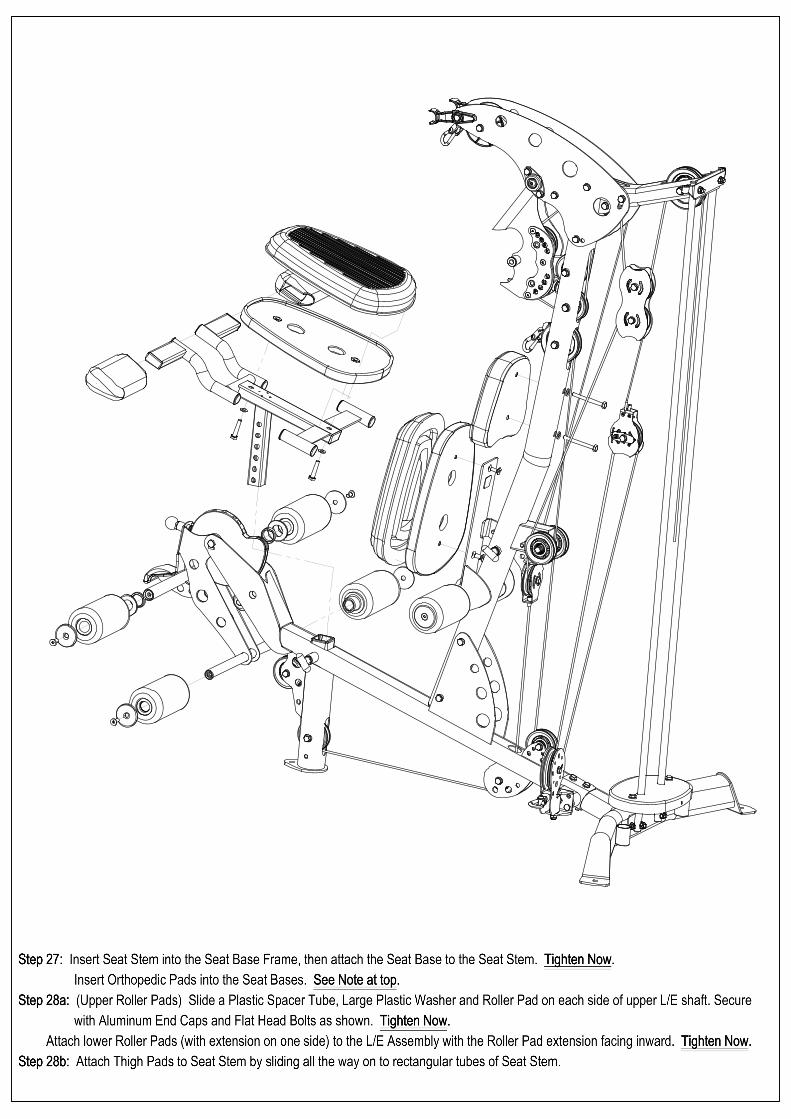
Step 25: Attach Head Pad to the Main Upright. Tighten Now. Step 26: Attach Seat Base to the Back Pad Tilt Frame. Tighten Now. Step 27: Insert Seat Stem into the Seat Base Frame, then attach the Seat Base to the Seat Stem. Tighten Now. Insert Orthopedic Pads into the Seat Bases. See Note at top. Step 28a: (Upper Roller Pads) Slide a Plastic Spacer Tube, Large Plastic Washer and Roller Pad on each side of upper L/E shaft. Secure with Aluminum End Caps and Flat Head Bolts as shown. Tighten Now. Attach lower Roller Pads (with extension on one side) to the L/E Assembly with the Roller Pad extension facing inward. Tighten Now. Step 28b: Attach Thigh Pads to Seat Stem by sliding all the way on to rectangular tubes of Seat Stem.
Step 30 1 – M5 x 12 Phillips Head Screw 1 – M5 Flat Washer
qxlwl
线条
qxlwl
线条
Ted Habing
Text Box
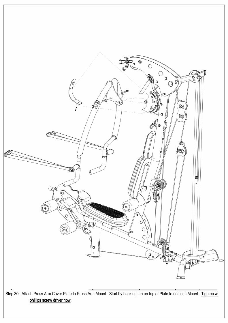
Step 29: Attach Press Arm to Press Arm Mount. Tighten now so there is no play but will swivel for adjustment. Requires force. Step 30: Attach Press Arm Cover Plate to Press Arm Mount. Start by hooking tab on top of Plate to notch in Mount. Tighten with phillips screw driver now.
Ted Habing
Text Box
Press Arm Mount
Ted Habing
Line
Ted Habing
Text Box
Press Arm Cover Plate
Ted Habing
Text Box
Press Arm
Ted Habing
Line
Ted Habing
Line
Ted Habing
Text Box
PAGE 15
qxlwl
标注
Remove Bolts from Guide Rods
qxlwl
线条
qxlwl
标注
IMPORTANT! Cable Bolt must be fully threaded into Selector Stem with Jam Nut tightened securely before using. Failure to do so may cause cable to come loose from weights and cause injury.
qxlwl
线条
qxlwl
线条
qxlwl
标注
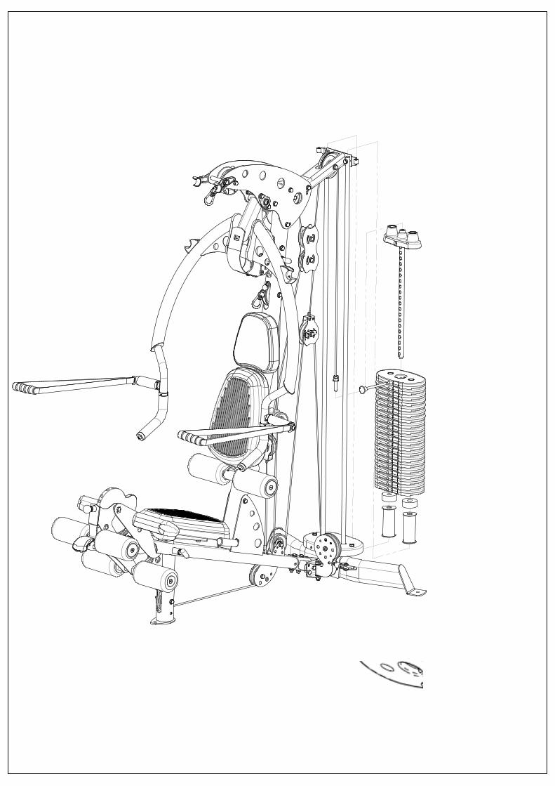
Step 31 Install Weight Stack Risers, Rubber Donuts, Weight Stack, Top Weight/Selector Stem (In That Order) Next reattach Guide Rods on front of plate with bolts that were removed. Tighten Now!!
qxlwl
标注
INSTALL WEIGHT STICKERS NOW Front of weight plate has recessed area for weight plate number. Slide Weight Pin into one of the weights after installed.
qxlwl
图章
qxlwl
标注
Bottom of weight plate has three feet.
qxlwl
线条
qxlwl
线条
qxlwl
线条
qxlwl
线条
Ted Habing
Line
Ted Habing
Text Box
Note: If installing optional 210 lb. (heavy) stack, do not use the Weight Stack Risers!!
Ted Habing
Line
Ted Habing
Line
Ted Habing
Text Box
PAGE 16
qxlwl
标注
Note: Be sure guide rods are positioned in front of plate.
qxlwl
线条
qxlwl
线条
qxlwl
标注
STEP 32 Shroud Plate Assembly
Ted Habing
Text Box
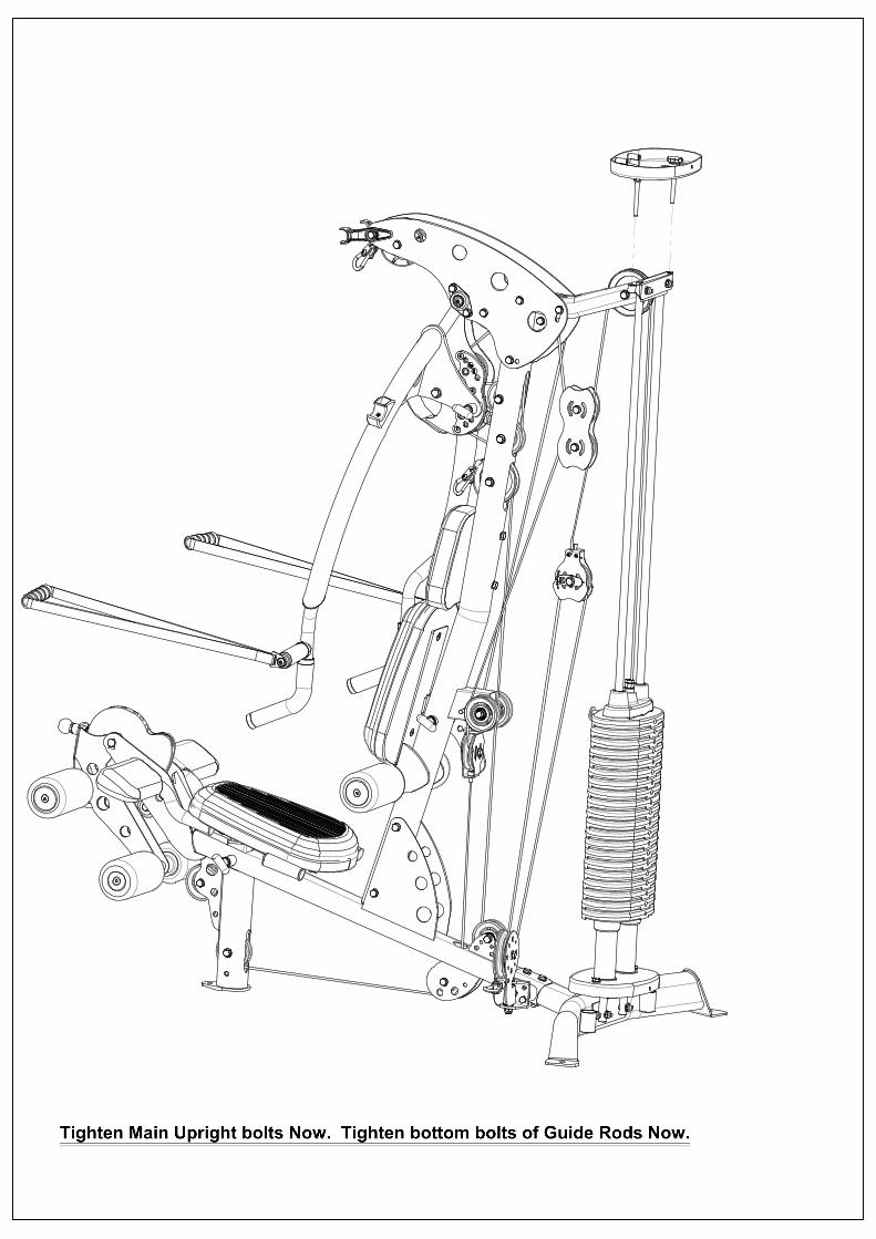
Step 32: Attach Shroud Plate to the Shroud Plate Bracket (Open Side Up) by screwing the bolts into the threaded parts on the Bracket. Use Knobs on top to screw each side all the way down. Tighten Main Upright bolts Now. Tighten bottom bolts of Guide Rods Now.
Ted Habing
Line
Ted Habing
Line
Ted Habing
Text Box
Tighten
Ted Habing
Text Box
Shroud Plate Bracket
Ted Habing
Line
Ted Habing
Text Box
PAGE 17
qxlwl
图章
qxlwl
标注
Step 33 3-Shroud Plate Connector Pins
qxlwl
线条
qxlwl
线条
qxlwl
线条
qxlwl
图章
qxlwl
线条
qxlwl
线条
qxlwl
标注
Step 34 3- T Pins
qxlwl
线条
qxlwl
线条
qxlwl
线条
Ted Habing
Text Box
Step 33: Slide a Shroud C Bracket into the pocket at one end of Shroud. (Pocket seam should face inside). Work shroud around bracket until the opening in the shroud lines up with the hole on the back of the bracket. Repeat this on the other end of shroud. Now position this shroud assembly around the upper and lower Shroud Mount Plates by working around guide rods and stack. Align holes in the top and bottom brackets with the holes in the plates and insert Shroud Plate Connector Pins in each (3 at top and 3 at bottom).
Ted Habing
Text Box
Next, stretch the shroud tight using the 2 knobs at the top, turn counter clockwise working between the 2 knobs to adjust each side up a little at a time.
Ted Habing
Text Box
Tightening Knobs
Ted Habing
Line
Ted Habing
Line
Ted Habing
Text Box
Step 34: The press arm starting position may be adjusted by screwing press arm stop in or out. Lock with jam nut when finished. Adjust cable slack at the upper single floating pulley by loosening bolt and moving pulley up or down with the selector plate. Lock tight with bolt when finished.
Ted Habing
Line
Ted Habing
Line
Ted Habing
Text Box
Adjust the Stop at the Single Floating Pulley for the leg extension to take slack out of the cable. Set the cam so the cable opening is in line with the 2 small pulleys before adjusting. Tighten the Jam Nut when finished.
Ted Habing
Line
Ted Habing
Text Box
PAGE 18
qxlwl
标注
STEP 35
qxlwl
线条
qxlwl
标注
STEP 36
qxlwl
线条
qxlwl
线条
qxlwl
标注
STEP 37
qxlwl
标注
STEP 38
qxlwl
线条
Ted Habing
Text Box
Attach all Accessories as shown.
Ted Habing
Text Box
PAGE 19
Ted Habing
Text Box
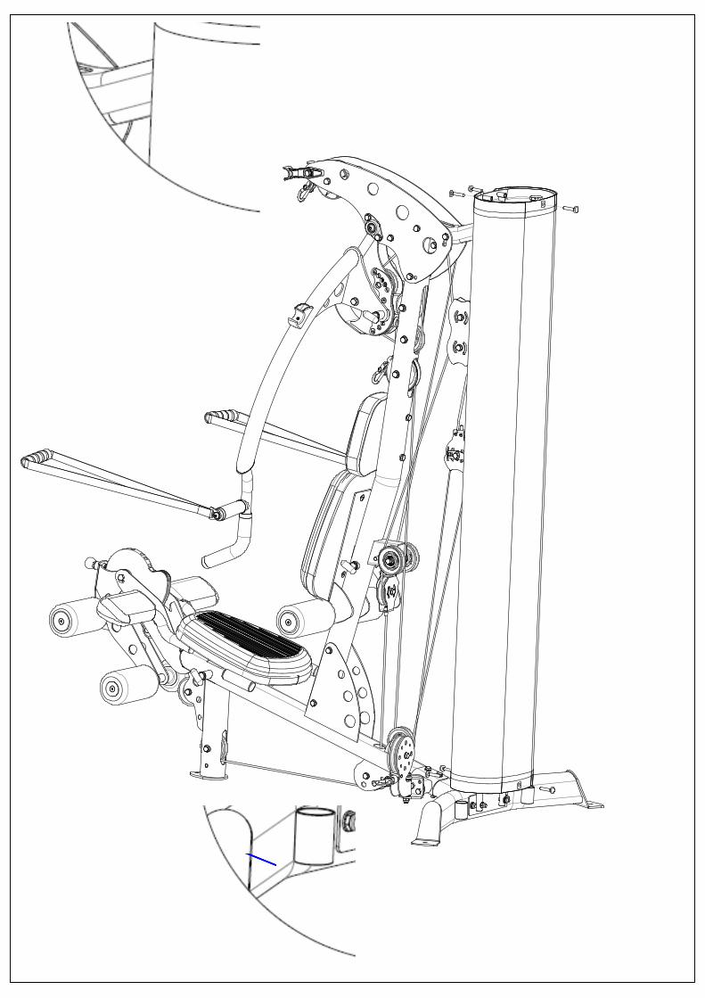
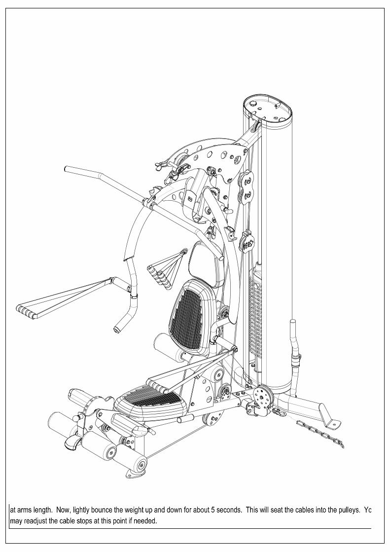
NOTE: At this point it is necessary to seat the cables. Start by verifying that cables are centered in the grooves of all pulleys. Next, select a weight you can comfortably handle on the bench press. Perform a seated bench press and hold the first repetition at arms length. Now, lightly bounce the weight up and down for about 5 seconds. This will seat the cables into the pulleys. You may readjust the cable stops at this point if needed.
877-738-1729
DECAL REFERENCE
PAGE 20
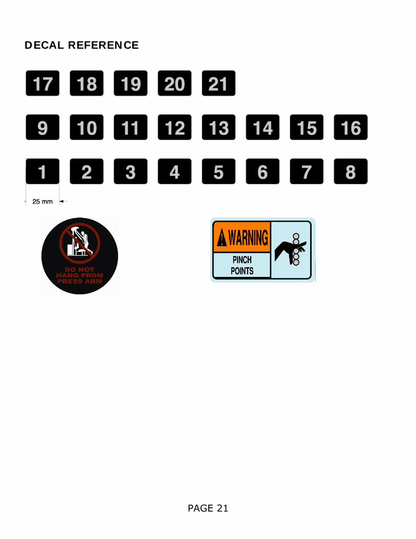
DECAL REFERENCE
PAGE 21
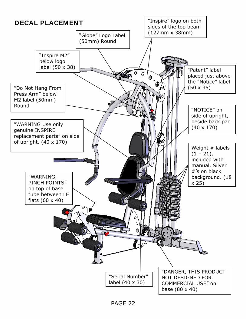
DECAL PLACEMENT
PAGE 22
“Globe” Logo Label (50mm) Round
“Inspire M2” below logo label (50 x 38)
“Do Not Hang From Press Arm” below M2 label (50mm) Round
“WARNING Use only genuine INSPIRE replacement parts” on side of upright. (40 x 170)
“WARNING, PINCH POINTS” on top of base tube between LE flats (60 x 40)
“DANGER, THIS PRODUCT NOT DESIGNED FOR COMMERCIAL USE” on base (80 x 40)
“Serial Number” label (40 x 30)
“Patent” label placed just above the “Notice” label (50 x 35)
“NOTICE” on side of upright, beside back pad (40 x 170)
Weight # labels (1 – 21), included with manual. Silver #’s on black background. (18 x 25)
“Inspire” logo on both sides of the top beam (127mm x 38mm)
ACCESSORIES • Exercise Wall Chart • Revolving Lat Bar • Revolving EZ Curl Bar • Ankle Strap• Abdominal Strap Handle MULTI-GYM OPTIONS • Colored Orthopedic Pads • Colored Shroud • Leg Press • Ab Crunch Bar Training Tips
CONSULT A PHYSICIAN BEFORE STARTING ANY EXERCISE PROGRAM
1. Always warm up before you start weight training. This helps get your muscles warm and prevents injury. You can warm up with light cardio or by doing a light set of each exercise before going to heavier weights.
2. Control the weight. Always work with a weight that you can handle through a full range of motion. Slow and steady movements are recommended.
3. Breathe. Don’t hold your breath during your set. Holding your breath builds internal pressure which increases your change for broken blood vessels, as well as a hernia.
4. Sit up straight. Pay attention to your posture and keep everything straight. Engage your abs in every movement to keep balanced and protect your spine.
PAGE 23
GENERAL MAINTENANCE INFORMATION Warning: DO NOT place styrofoam or printed materials on the orthopedic seat pads. Over time, these may stick to the pads and mar the surface. Do not leave items sitting on the orthopedic seat pads, these pads have a special density that takes shape to objects and small objects will leave imprints in the surface that may take time to come out. • Periodically inspect the cables for splitting, cracking or fraying. Also, watch for bulging or flat areas in the cable. • Immediately replace cables at the first signs of damage or wear. Never use equipment with damaged or worn cables. • Cables naturally stretch over time, so check cable slack periodically and adjust cable tension as needed. • Regularly inspect product for loose hardware. • Do not use or store equipment outdoors. • Inspect snap links, swivels, handles, and weight stack pins for wear or damage. If wear or damage exists, replace immediately. • Locate and familiarize yourself with all warning decals on the multi-gym. • Replace damaged or worn upholstery immediately. • Periodically wipe down guide rods with a dry cloth and re-apply a thin coat of a teflon-based lubricant.
PAGE 24
MAINTENANCE SCHEDULE
ROUTINE HOME MAINTENANCE ENTRY DATE
Inspect: Links, Pull Pins, Spring Clips, Swivels, Weight Stack Pins
WEEKLY
Clean: Upholstery WEEKLY
Inspect: Cables and their Fittings WEEKLY
Inspect: Tautness of all Shrouds WEEKLY
Inspect: Accessory Bars and Handles 3 MONTHS
Inspect: All Decals 3 MONTHS
Inspect: All Nuts and Bolts. Tighten if Needed 3 MONTHS
Inspect: Anti-Skid surfaces 3 MONTHS
Clean and Lubricate: Guide Rods with a Teflon based lubricant
3 MONTHS
Lubricate: Seat Sleeves and all Plastic Slides 3 MONTHS
Clean and Wax: All Glossy Finishes YEARLY
Replace: Cables, Belts and Connecting Parts 2 YEARS
PAGE 25
Warranty. This Warranty applies to Inspire Strength products manufactured or distributed by Health In Motion LLC. CONSUMER USE: LIGHT-COMMERCIAL USE: LIMITED LIFETIME FRAME: LIMITED LIFETIME FRAME: Includes Frame and Welds Includes Frame and Welds LIMITED LIFETIME PARTS: 10 YEAR PARTS: Includes Upholstery, Hardware, etc. Includes Upholstery, Hardware, etc. LIMITED LIFETIME MOVING PARTS: 10 YEAR MOVING PARTS: Includes Pulleys, Cables, etc. Includes Pulleys, Cables, etc.
PLEASE NOTE THAT NOT ALL INSPIRE PRODUCTS ARE MADE FOR LIGHT-COMMERCIAL USE Refer to your Owner’s Manual or consult with you fitness product dealer to establish if a Product is made for light-commercial use or not. Using a non-commercial product in a commercial setting can result in serious injury or death! Health In Motion warrants that the Product you have purchased for light-commercial, personal, family or household use from Health In Motion LLC or from an authorized Health In Motion reseller is free from defects in materials or workmanship under normal use during the warranty period. Your sales receipt, showing the date of purchase of the Product, is your proof of the date of purchase. This warranty extends only to you, the original purchaser. It is not transferable to anyone who subsequently purchases the Product from you. It excludes expendable parts such as paint and finish. This Warranty becomes VALID ONLY if the Product is assembled / installed according to the instructions / directions included with the Product.
Replacement and repair of parts. During the warranty period Health In Motion will, at no additional charge, repair or replace the Product if it becomes defective, malfunctions, or otherwise fails to conform with this Warranty under normal light-commercial, personal, family, or household use. In repairing the product Health In Motion may replace defective parts with, at the option of Health In Motion, serviceable used parts that are equivalent to new parts in performance, or new parts. All exchanged parts and Products replaced under this warranty will become the property of Health In Motion. Health In Motion reserves the right to change manufacturers and or specification of any part to cover any existing warranty.
Service procedures. To obtain warranty parts, you must return the parts to Health In Motion or an authorized Health In Motion retailer in its original container (or equivalent). You must pre-pay any shipping charges, taxes, or any other charges associated with transportation of the Product. In addition, you are responsible for insuring any Product shipped or returned. You assume the risk of loss during shipment. You must present Health In Motion with proof-of-purchase documents (including the date of purchase, Model, and Serial Number). Any evidence of alteration, erasing or forgery of proof -of-purchase documents will be cause to void this Warranty. Register your warranty online visit www.inspirefitness.net
Conditions and Exceptions. This Warranty does not extend to any Product not purchased from Health In Motion LLC or from an authorized Health In Motion reseller. This Warranty does not extend to any Product that has been damaged or rendered defective; (a) as a result of accident, misuse, or abuse; (b) by the use of parts not manufactured or sold by Health In Motion; (c) by modification of the Product; (d) as a result of service by anyone other than Health In Motion, or an authorized Health In Motion warranty service provider; (e) product that has not been properly maintained (follow maintenance schedule found on product). Should any product submitted for Warranty service be found to be ineligible, an estimate of repair cost will be furnished and the repair will be made if requested by you upon Health In Motion receipt of payment or acceptable arrangement of payment.
Disclaimer EXCEPT AS EXPRESSLY SET FORTH IN THIS WARRANTY HEALTH IN MOTION MAKES NO OTHER WARRANTIES; EXPRESSED OR IMPLIED INCLUDING ANY IMPLIED WARRANTIES OF MERCHANTABILITY AND FITNESS FOR A PARTICULAR PURPOSE. HEALTH IN MOTION EXPRESSLY DISCLAIMS ALL WARRANTIES NOT STATED IN THIS WARRANTY. ANY IMPLIED WARRANTIES THAT MAY BE IMPOSED BY LAW ARE LIMITED TO THE TERMS OF THIS WARRANTY. NEITHER HEALTH IN MOTION NOR ANY OF ITS AFFILIATES SHALL BE RESPONSIBLE FOR INCIDENTAL OR CONSEQUENTIAL DAMAGES. HEALTH IN MOTION IS NOT RESPOSIBLE FOR THE REPAIR OR REPLACEMENT OF ANY PARTS THAT HEALTH IN MOTION DETERMINES HAVE BEEN SUBJECTED AFTER THE DATE OF MANUFACTURE TO ALTERATION, NEGLECT, ABUSE, MISUSE, NORMAL WEAR & TEAR, ACCIDENT, DAMAGE DURING TRANSIT OR INSTALLATION, FIRE, FLOOD, OR ANY ACT OF GOD. SOME STATES DO NOT ALLOW LIMITATIONS ON HOW LONG AN IMPLIED WARRANTY LASTS OR THE EXCLUSION OR LIMITATION OF INCIDENTAL OR CONSEQUENTIAL DAMAGES, SO THE ABOVE LIMITATIONS OR EXCLUSION MAY NOT APPLY TO YOU. This Warranty gives you specific legal rights and you may also have other rights that may vary from state to state. This is the only express warranty applicable to Health In Motion’s “Inspire” branded strength products. Health In Motion neither assumes nor authorizes anyone to assume for it any other express warranty.