assembly & operation - reid lifting – aluminium portable … … · · 2014-07-11 &...
TRANSCRIPT

ASSEMBLY & OPERATION GUIDEwww.reidlifting.com
Assembly & Operation
LIGHTWEIGHT PORTABLE SAFE
ASSEMBLY VIDEO
CONTENTS
INTRODUCTION
CORRECT OPERATION• Inspection Prior To Initial Operation
• Inspection Before Starting Work
• Maximum Capacity
• Notes For Correct Usage
• Warning
• Attaching The Load
• Temperature Range
• Regulations
• Inspection/Maintenance
• Regular Inspections
• Maintenance/Repair
• Marking
• ATEX
• Language
ASSEMBLY INSTRUCTIONS
DIMENSIONS
QUALITY & SAFETY• Accreditations
INSPECTION RECORD
N.B. This document should form an element of the overriding Risk Assessment and Method Statement required for each lift.
No. 1 in lightweight, portable, safe lifting solutions
2
Tel: +44 (0)1291 620796 www.reidlifting.com
INTRODUCTIONAll users must read these operating instructions carefully prior to the initial operation. These instructions are intended to acquaint the user with the PORTA-GANTRY RAPIDE and its key options to enable him/her to use it to the full extent of its intended capabilities.
The operating instructions contain important information on how to handle the PORTA-GANTRY in a safe, correct and economic manner. Acting in accordance with these instructions helps to avoid dangers, reduce repair costs and down time and to increase the reliability and lifetime of the PORTA-GANTRY.
Anyone involved in doing any of the following work with the gantry frame must read the operation instructions, be trained and competent in its safe use and act accordingly:
• operation, including preparation, trouble shooting during operation and cleaning
• maintenance, inspection, repair
• transport
Apart from the operating guide, health & safety and the accident prevention act valid for the respective country and area where the gantry frame is used, the commonly accepted regulations for safe and professional work must be adhered to.
It is incumbent on the user or instigator of work with the equipment that all users have suitable medical and physical capabilities. Likewise the competent person should ensure there is a rescue plan in place in the event of an emergency that could occur during the work.
N.B. This document should form an element of the overriding Risk Assessment and Method Statement required for each lift.
LIGHTWEIGHT PORTABLE SAFE

CORRECT OPERATIONInspection prior to initial operationEach PORTA-GANTRY frame must be inspected prior to initial operation by a competent person. The inspection is visual and functional and shall establish that the structure is safe and has not been damaged by incorrect assembly, transport or storage. Inspections are instigated by the user.
Inspection before starting workThe inspection procedure requires that a valid inspection/test certificate has been submitted to and checked by the user.
Before starting work inspect the gantry frame assembly and all load-bearing components for visual defects. Check the integrity of all profiles for denting and pin/bolt holes for wear and elongation. Furthermore, test the trolley for free movement along the beam and check the operation of the footing option.
Ensure that the overall WLL limit is adhered to – following the necessary Risk Assessment and Method Statement.
Maximum capacityThe PORTA-GANTRY RAPIDE is designed to lift and lower loads up to its rated capacity. The capacity indicated on the frame is the maximum working load limit (WLL) or safe working load (SWL) which must not be exceeded (definition is country dependent).
When being used as a personnel lifting anchor the user must use a body harness and retractable device or shock absorber to EN355 , ANSI Z359.6-09 or CSA Z259.16-04 that limits the maximum allowed force (M.A.F.) to 6kN. Winches used with the PORTA-GANTRY RAPIDE should comply to EN1496:2006 or equivalent.
Only ONE person / load may be attached to ONE trolley in accordance with the WLL’s.
The PORTA-GANTRY RAPIDE has different ratings depending upon the application as detailed in the table below.
The gantry has an up-rated capacity for personnel positioning. This is when the structure is to be used as an anchor for lifting persons that have a suitably low chance of falling through a free distance and only carried out following a comprehensive risk assessment.
While the PORTA-GANTRY RAPIDE has the capacities stated below it is only one part of a fall arrest system which is only as strong as its lowest rated component. Each lift must be properly planned and all weights clearly known along with the WLL’s and constraints of all fall arrest system devices.
The capabilities stated in the table below are only applicable to the standard RAPIDE configurations i.e. small, medium and tall. Bespoke versions of the RAPIDE are available tailored to specific lifting needs. If unsure about your system consult serial labels, information filled in on page 23 or consult your supplier. A custom RAPIDE is designated by a product number ending with a “C” found on the serial label attached to each A-frame and the beam. For custom
No. 1 in lightweight, portable, safe lifting solutions
4
Model PGRS20 PGRS23, PGRM20, PGRM23PGRS40, PGRM40, PGRT20,
PGRT23, PGRT40
Application WLL (kg) Capacity [Persons] WLL (kg) Capacity
[Persons] WLL (kg) Capacity [Persons]
Fall Arrest 140 3 140 2 140 1
Personnel positioning
250 3 200 2 125 1
Goods 500 N/A 400 N/A 250 N/A
designed RAPIDEs please contact your supplier for appropriate rating and capabilities.
In the event of simultaneous goods and personnel combined lifting or when being used as a fall arrest system in sub-zero AND wet conditions contact the supplier as capacities may be reduced.
NOTE 1. We recommend the use of a load-sensing device on
all lifts.
2. The Gantry should NOT be moved under load. Any deviation from this should be supported by a risk assessment and method statement.
3. The WLL (or SWL) rating must NOT be exceeded – risk assessment & method statement must consider additional loading in “wet lift” situations.
4. Ensure suitable winches and connection plates are used for all applications – see winch bracket installation on pg 15.
NOTES FOR CORRECT USAGE
• Due care and attention should be practiced when transporting and storing gantry to avoid damage.
• Do not throw the gantry or its components down or stack items on top of it. Always place properly on the ground avoiding damage to the equipment.
• Assemble only as instructed (ensure all pins and bolts are present and fitted correctly as per instructions).
• We recommend that gloves should be worn when using this equipment.
• We recommend single person assembly to avoid conflicting actions.
• Set up the gantry at a safe distance from the hazard and subsequently move the structure into place.
• The beam must be horizontal prior to any lift and A-frames vertical and parallel to each other.
• Do not use the gantry frame if the trolley does not run freely along the beam.
• Trolleys have the ability to be locked into position on the beam for certain applications. e.g. when gantry is used as a restraint point.
• Attach hoist only to the lifting point on the trolley.
• Avoid side pull. Lowering and lifting should only be carried out when the load chain/lifeline form a straight and vertical line between the load and lifting attachment point on the trolley.
• Do not allow load to swing.
• When lifting keep the load low to the ground.
• NEVER walk away from structure whilst still being connected.
• Only raise and lower loads when castor brakes are engaged.
• When using the gantry as a fall arrest anchor the required clearance of the fall arrest device should be considered - refer to device Assembly & Operation manual and consider the height adjustment on the gantry.
• Before the gantry is used consideration must be given to the potential effects of the lifelines over sharp edges, chemical reagents, electrical conductivity, cutting, abrasion, climatic exposure and the effect of offset forces as a result of pendulum falls.
• The gantry is not to be moved under load except when a Competent Person or authority approves a risk assessment and a method statement for a particular reason.
LIGHTWEIGHT PORTABLE SAFE
Tel: +44 (0)1291 620796 www.reidlifting.com

Warning
• The equipment shall not be used outside its limitations, or for any purpose other than that for which it is intended.
• Only one lifeline should be used with each sheave and they should never cross paths with each other.
• Do not lift or transport loads while personnel are in the danger zone.
• Do not allow personnel to pass under a suspended load.
• When gantry is used with multiple persons attached working procedures should dictate that individual lifelines do not cross and become tangled.
• It is NOT recommended to mix the use of the gantry with personnel and goods lifting concurrently.
• After lifting, a load must not be left unattended for a long period of time.
• Start moving the load along the beam only after it has been attached correctly and all personnel are clear of the danger zone.
• Be aware of hazards when setting up/folding down, eg. hands/fingers trapped in rotating parts.
• It is essential for safety that the PORTA-GANTRY RAPIDE is withdrawn from use immediately should:
1) any doubt arise about its condition for safe use or;
2) it has been used to arrest a fall and not be used again until confirmed in writing by a competent person that it is acceptable to do so.
Attaching the loadThe operator must ensure that the hoist is attached in a manner that does not expose him or other personnel to danger by the hoist, chain(s) or the load.
Temperature rangeThe PORTA-GANTRY RAPIDE can be operated in ambient dry temperatures between -20° and +55°C (-4°F to 131°F). Consult your supplier in case of extreme working conditions. If used in sub-zero and wet conditions, fall arrest appliances characteristics may change.
RegulationsThe PORTA-GANTRY RAPIDE complies with the following regulations:
PPE Directive 89/686/EEC, Machinery Directive 2006/42/EC, The Provision and Use of Work Equipment Regulations 1998 (S.I. 1998 No. 2306), The Lifting Operations and Lifting Equipment Regulations 1998 (S.I. 1998 No. 2307). The safety regulations of the respective country for using manual lifting equipment must be strictly adhered to. EN795:1997, ANSI Z359.1-2007 and CSA Z259.16-04 certified.
INSPECTION/MAINTENANCE
Regular inspectionsTo ensure that the gantry frame remains in safe working order it must be subjected to thorough periodic inspections by a competent person. Inspections are to be 6 monthly for personnel lifting and 12 monthly for goods only unless adverse working conditions or profile of use dictate shorter periods. The components of the gantry frame are to be inspected for damage, wear, corrosion or other irregularities. To check for worn parts it may be necessary to disassemble the gantry frame.
Repairs should only be carried out by an approved specialist workshop that uses original spare parts.
If using the Gantry in explosive atmospheres see additional section titled ATEX.
No. 1 in lightweight, portable, safe lifting solutions
6

Inspections are instigated by the user. If detailed information is required on inspection and test criteria, please refer to your supplier’s technical department.
Please refer to pg 23 for the equipment inspection sheet.
Maintenance/RepairIn order to ensure correct operation not only the operations instructions, but also the conditions for inspection and maintenance must be complied with. If defects are found stop using the PORTA-GANTRY immediately.
No alterations or additions to the equipment should be made without the written consent of the manufacturer. Any repair shall only be carried out in accordance with the manufacturer’s procedures.
It is recommended to maintain the equipment in a clean and dry manner. Cleaning is suggested using a sponge or cloth with warm, soapy water (using diluted domestic washing up liquid), rinsing and allowing to dry.
MarkingThe serial labels indicate:
• The product identification number.
• The products unique serial number.
• The goods WLL of the device.
• The year of manufacture.
• The standards to which the device is approved.
• The ATEX rating of the product (if applicable) - see ATEX section below.
• CE 0088: Notified body number (currently LRQA) who are responsible for approving REID Lifting’s quality control system.
Read the Assembly & Operation instructions.
PORTA-GANTRY RAPIDE 500kg Assembly & Operation instructions.
Equipment capacity warning label: refer to maximum capacity section for rating explanations.
ATEX: This product has been designed for use in explosive atmospheres. If the product is to be used in explosive atmospheres then the following section must be followed. Any different or exceeding use is considered incorrect and REID Lifting Ltd will not accept any responsibility for damages resulting from false application. The risk is solely with the user. If the product has been customised in any way then it may not comply with standards and not be suitable for use in explosive atmospheres. If this is the case then the product will not have any of the below marking. If in doubt contact your REID representative.
ATEX - ClassificationAs standard, the product meets the requirements of Category 3 equipment for use in Zone 2 explosive atmospheres, providing a normal level of protection where mixtures of air and gases, vapours or mists or by air/dusts mixtures are unlikely to occur or, if they do occur, are likely to do so only infrequently and for a short period only. Or;Available as an upgrade the product can be supplied to meet the requirements of Category 2 equipment for use in Zone 1 explosive atmospheres, providing a high level of protection where mixtures of air and gases, vapours or mists or by air/dusts mixtures are likely to occur.
ATEX - IdentificationIn addition to the previous marking section the product will have the following identification on the serial label:
As standard for Zone 2 atmospheres:
LIGHTWEIGHT PORTABLE SAFE
Tel: +44 (0)1291 620796 www.reidlifting.com

No. 1 in lightweight, portable, safe lifting solutions
II 3 GD T6
Identification for protection against explosions II: Unit group II – non-mining application 3: Category 3 – Normal safety for use in Zone 2 GD: For use in gas (G) & dust (D) atmospheres T6:Temperature class – Max 85°C
Or;
As an upgrade for use in Zone 1 environments:
II 2 GD T6
Identification for protection against explosions II: Unit group II – non-mining application 2: Category 2 – High safety for use in Zone 1 GD: For use in gas (G) & dust (D) atmospheres T6:Temperature class – Max 85°C
ATEX - Spark FormationIncreased danger of ignition may emanate from clashing of special material pairings. These are non corrosion-resistant steel or cast iron against aluminium, magnesium or pertinent alloys. This applies especially in case of rust or surface rust. When assembling the product and inserting fastening components; they must be clear of rust and debris of any kind. Care must be taken to ensure the product is handled in a suitable manner and is never thrown, and always placed, onto the ground.
ATEX - Static ElectricityFor Zone 2 applications static electricity has been identified as potential for build up leading to an incendive spark. Although the risk of such ignition is unlikely the gantry must be earthed during assembly and use. This can be achieved by attaching a 4mm earthing lead to a convenient location on metallic parts of both the Gantry and Trolley.
In Zone 1 applications, for added explosion protection, the gantry is fitted with anti-static trolley rollers, electrically conductive castors and electrically conductive
transport wheels and therefore does not need to be earthed.
ATEX - Inspection, Maintenance & RepairIf using the gantry in explosive atmospheres, in addition to the regular inspection/maintenance information found on page 6, these additional instructions should be followed.
Inspections shall be instigated by the user and occur at least 6 monthly or sooner if adverse operating conditions or profile of use dictate shorter periods. Inspections and maintenance shall be carried out at a safe distance away from an explosive atmosphere. Special attention should be given to dust deposits on the structure, especially in areas where the profiles come into contact, and should be wiped clean and care taken not to apply materials that could create electrostatic charging. Additionally the bearings in the trolley rollers and castors should be checked to ensure they rotate freely. The structure is predominantly constructed from aluminium which will not rust. However there are steel components used throughout. These are the fasteners, castors, master-link, trolley rollers, A-frame height adjustment gearing system (if fitted) and the height adjustment ratchet (if fitted). Where there is sign of any rust deposits on the aluminium structure it should be wiped clean as above and where there is sign of rust on a steel component then that component should be removed from use and the structure not used until a replacement is fitted.
LANGUAGE It is essential for the safety of the user that if this product is re-sold outside the original country of destination the reseller shall provide instructions for use, maintenance, for periodic examination and for repair in the language of the country in which the product is to be used.
8

LIGHTWEIGHT PORTABLE SAFE
If installed there may be location points on the upper and lower uprights to enable storing of trolleys. The lower upright is only accessible when the upper is rotated out of the way.
N.B. Larger RAPIDE variants do not have stow pegs to allow the trap plates to slide further up the upright for increased collapsibility.
N.B. Appropriate PPE should be worn • Gloves • Protective footwear • Hard hat
For trolleys stowed on underside upright, if stow pins available, removal can only take place when the upper A-frame assembly is rotated out of the way, or when gantry is set up.
• To stow trolley reverse process 1—2.
• If storing on underside upright, store before collapsing or before the upper A-frame assembly is rotated to its final position.
• Note which side the pins are inserted on the upper upright as above. For the lower upright, pins are inserted from other side to avoid interferences with folding i.e. from opposite side as above.
1. Remove pin from trolley. For sheaved trolley 2 pins need to be removed
2. Rotate underside plate to open the trolley and lift off stow pin
Trolley Stow and Removal
ASSEMBLY INSTRUCTIONS
Trolley Storing
9
Tel: +44 (0)1291 620796 www.reidlifting.com

No. 1 in lightweight, portable, safe lifting solutions
Pre set-up checks
• Ensure castors are locked
• Allow sufficient clearance for gantry frame rotation. If sufficient space not available see steps 11 to 17.
3. Rotate first leg assembly to a vertical position.
5. Open leg and insert aircraft/ball-lock pin into second hole securing the leg in its open position.Repeat for second leg.
4. While in this vertical position remove ball lock pin from its stow hole.
6. Continue rotation of leg assembly until it comes to rest on ground.
Gantry Set-Up
10
LIGHTWEIGHT PORTABLE SAFE
11
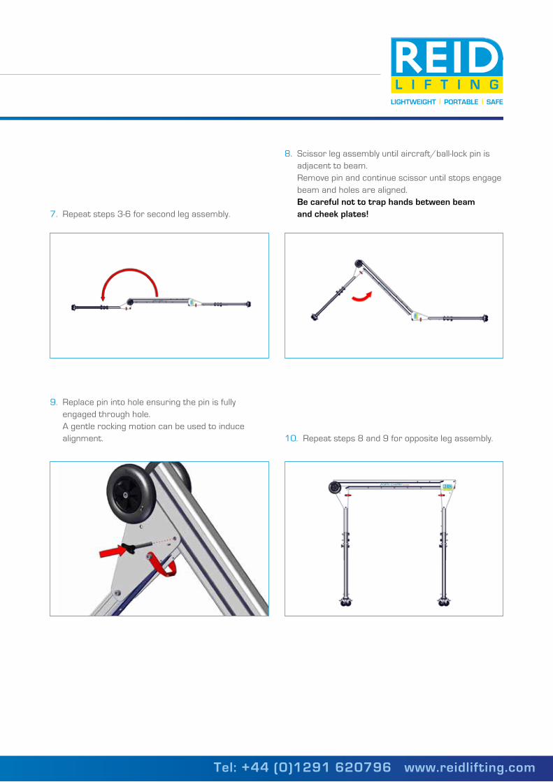
7. Repeat steps 3-6 for second leg assembly.
9. Replace pin into hole ensuring the pin is fully engaged through hole. A gentle rocking motion can be used to induce alignment.
8. Scissor leg assembly until aircraft/ball-lock pin is adjacent to beam. Remove pin and continue scissor until stops engage beam and holes are aligned. Be careful not to trap hands between beam and cheek plates!
10. Repeat steps 8 and 9 for opposite leg assembly.
Tel: +44 (0)1291 620796 www.reidlifting.com
No. 1 in lightweight, portable, safe lifting solutions
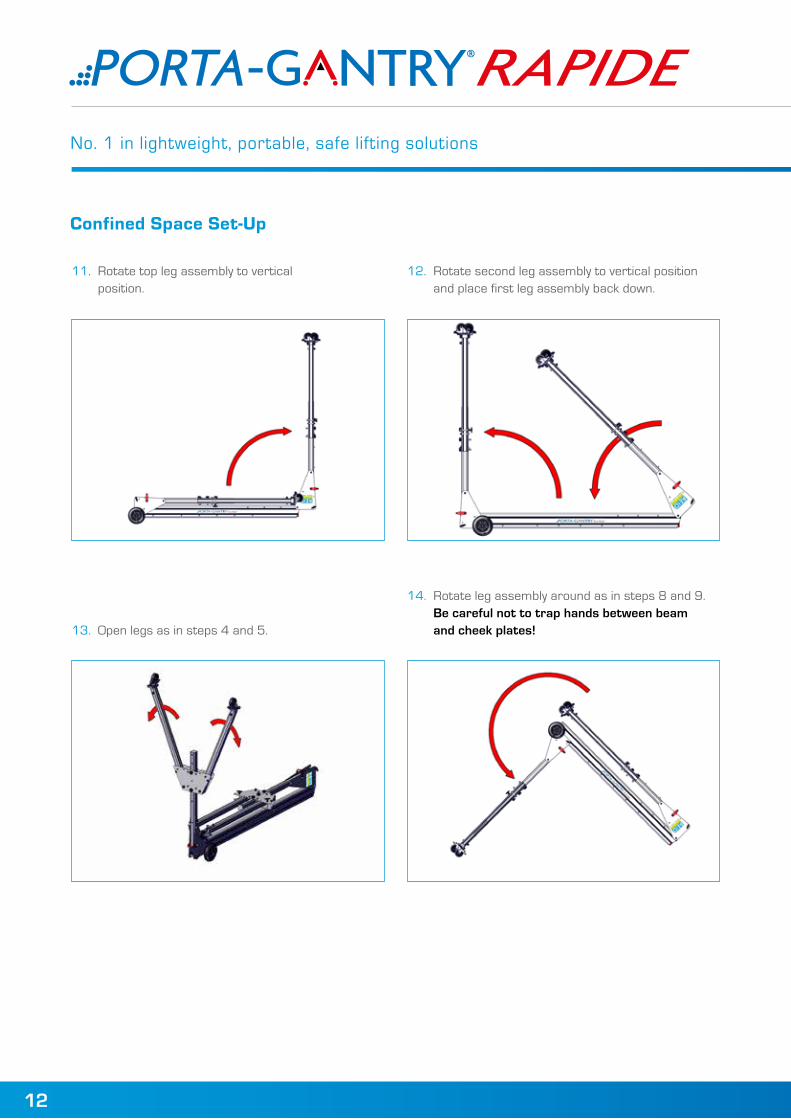
11. Rotate top leg assembly to vertical position.
13. Open legs as in steps 4 and 5.
12. Rotate second leg assembly to vertical position and place first leg assembly back down.
14. Rotate leg assembly around as in steps 8 and 9. Be careful not to trap hands between beam and cheek plates!
Confined Space Set-Up
12

LIGHTWEIGHT PORTABLE SAFE
15. Rotate second leg assembly to vertical posi-tion and open legs as in steps 4 and 5.
Ensure all quick release bolts are hand tight and aircraft/ball-lock pins are secure.Ensure all quick release bolts are hand tight and aircraft/ball-lock pins are secure.
If space is further limited for set up then the legs can be removed.
17. Remove legs from the upright and rotate as per step 14 While legs removed they can be opened and assembled back onto gantry as in step 14 Repeat 17 for opposite leg assembly and assemble as per step 15
16. Rotate leg assembly around as in steps 8 and 9. Be careful not to trap hands between beam and cheek plates!
13
Alternative Confined Space Set-Up
Tel: +44 (0)1291 620796 www.reidlifting.com

No. 1 in lightweight, portable, safe lifting solutions
Be careful not to allow plate to swing open uncontrolled.
18. When collapsing gantry ensure to stow beam aircraft/ball-lock pins in cheek plate holes to ensure they do not become damaged.
To collapse gantry reverse steps 10 to 1 for normal collapse or steps 16 to 11 and steps 2 to 1 for confined space.
If trolleys are required to be locked into position then an additional pin is available to provide trolley lock-off.
20. Close trolley plate encapsulating the beam and insert aircraft/ball-lock pin. Observe pin is properly engaged through holes.
19. Remove pin. Open trolley and present to beam with plate rotated through 90°.
Gantry Stowage
Master-link/Close-Coupled Trolley Installation
14

LIGHTWEIGHT PORTABLE SAFE
15
21. Remove existing bolt, A or C. Present bracket to gantry as shown (with locating pin at bottom) and insert new, longer bolts securing the winch with the quick release knobs provided.
N.B. Illustration shows one example of many winches, fall arrests and interface brackets available.
22. Place winch onto locating pin, D. Rotate winch to align holes, E. Place retaining pin into holes, F. Observe pin is securely engaged.
Never install winch bracket while gantry is under load. Only install winches which are approved by REID for use with the PORTA-GANTRY RAPIDE and a suitable interface / mounting plate supplied.
Winch can be installed on both sides of gantry and on either bolts A and B or B and C. Ensure winch bracket and quick release knobs are hand tight.
Winch Bracket Installation
Winch Installation
Tel: +44 (0)1291 620796 www.reidlifting.com

No. 1 in lightweight, portable, safe lifting solutions
23. Thread rope through plates and capture rope between sheave and beam. Secure sheave by aircraft/ball-lock pin. Observe pin is securely engaged.
25. Insert second pin as shown Observe both pins are fully engaged
24. Present trolley to underside of beam Capture rope between sheave and beam and insert pin as shown
Sheave Trolley Installation
16

LIGHTWEIGHT PORTABLE SAFE
17
26. Take weight of gantry upright. Remove bolts and adjust to the desired position.Re-insert bolts and hand tighten quick release knobs ensuring the gantry is secure.
27. Remove quick release bolt and handle. Store handle in safe place.
Beam width adjustment can take place during steps 6 or 7.
28. Move leg assembly to required position. Re-insert bolt and hand tighten quick release knob.Complete assembly of gantry as steps 8-10.
Never adjust the height while the gantry is under load.
Height Adjustment
Beam Width Adjustment
Tel: +44 (0)1291 620796 www.reidlifting.com

No. 1 in lightweight, portable, safe lifting solutions
29. The foot option can be changed by removing the nut cap and undoing the bolts. Tools required: 20mm spanner & 13mm allen key. Tighten to 25Nm torque or until spring washer is fully depressed.
30. To increase height pull foot down until desired position is achieved.
• Ensure all ball lock pins are fully engaged into their respective holes.• Ensure all quick release knobs (on trap plates and at beam) are hand tight and secure.• Ensure gantry is level.
31. To decrease height depress lever and push foot up to desired position. Observe gantry is level.
Never adjust the height while the gantry is under load.
Changing the Foot Option
Foot Adjustment
Pre-lift Checks
18

LIGHTWEIGHT PORTABLE SAFE
19
Patent Pending
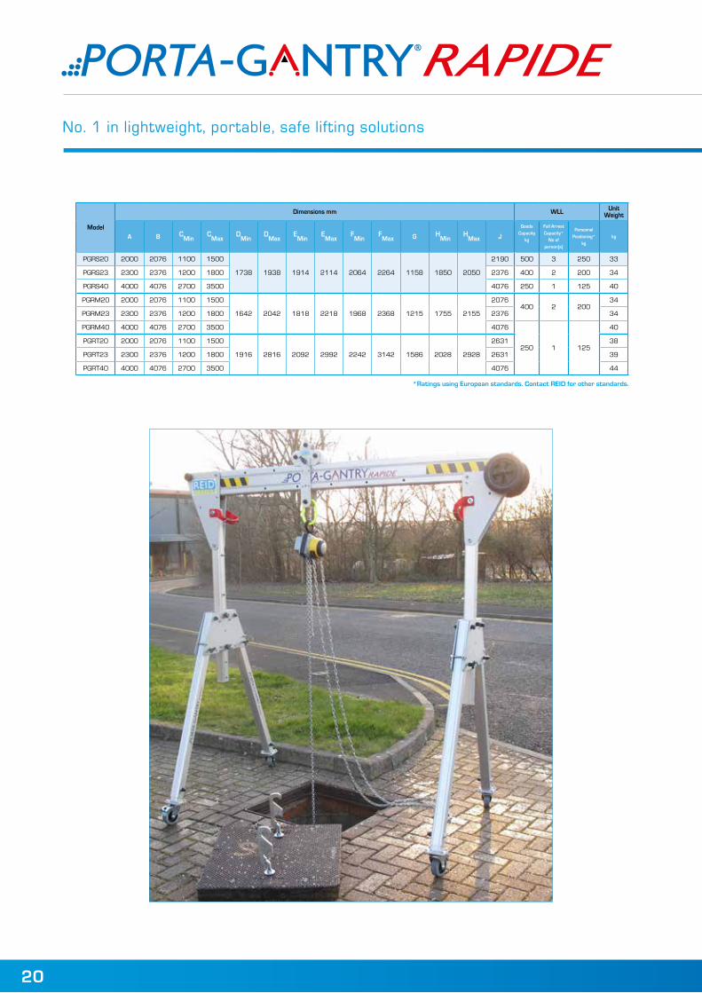
DIMENSIONS
440
415
Tel: +44 (0)1291 620796 www.reidlifting.com
No. 1 in lightweight, portable, safe lifting solutions
EN795 Class B LEEA Membership ISO 9001 ISO 14001 OHSAS 18001
The Queen’s Award for Enterprise Innovation
Unit 1 Severnlink, Newhouse Farm Industrial Estate, Chepstow, Monmouthshire NP16 6UN, UK
LIGHTWEIGHT PORTABLE SAFE
PGRPO/EN/V7/14/04
• Dual rated for goods and personnel lifting
- Goods rated up to WLL 500kg - Designed to exceed EN795 Class B*, OSHA, ANSI and
CSA standards - Personnel rated up to WLL 250kg - Up to 3 x person fall arrest capability in a range of
configurations** - Adaptable, multi purpose trolleys – goods
& personnel lifting
• Load bearing, lockable castors for easy positioning***• Range of beam lengths and configurations available
*Notified Body Approval: SGS UK (0120)
**Fall arrest capability reduced when goods load simultaneously applied
*** ACOP – advises no gantry movement under load except where a“competent person” has undertaken a suitable Risk Assessment &Method Statement and deems appropriate.
Patent Pending
The Facts:
DIMENSIONS
440
415
*Ratings using European standards. Contact REID for other standards.
Model
Dimensions mm WLL Unit Weight
A B CMin
CMax
DMin
DMax
EMin
EMax
FMin
FMax G H
MinH
Max J
Goods Capacity
kg
Fall Arrest Capacity*
No of person(s)
Personnel Positioning*
kgkg
PGRS20 2000 2076 1100 1500
1738 1938 1914 2114 2064 2264 1158 1850 2050
2190 500 3 250 33
PGRS23 2300 2376 1200 1800 2376 400 2 200 34
PGRS40 4000 4076 2700 3500 4076 250 1 125 40
PGRM20 2000 2076 1100 1500
1642 2042 1818 2218 1968 2368 1215 1755 2155
2076400 2 200
34
PGRM23 2300 2376 1200 1800 2376 34
PGRM40 4000 4076 2700 3500 4076
250 1 125
40
PGRT20 2000 2076 1100 1500
1916 2816 2092 2992 2242 3142 1586 2028 2928
2631 38
PGRT23 2300 2376 1200 1800 2631 39
PGRT40 4000 4076 2700 3500 4076 44
20

LIGHTWEIGHT PORTABLE SAFE
Quality and Safety are key themes throughout this document and the REID Lifting ethos. It is with this in mind that we have undertaken external accreditations to ensure we stay focused on what is important to our clients and users and ahead of market trends and developments in Safety and Quality systems.
REID Lifting has been successfully audited by Lloyds Register (LRQA) for approval of its Integrated Management System combining quality systems management, environmental issues and the Health and Safety practices within the company.
REID Lifting holds the following certifications:
• ISO 9001 - Specifies requirements for a quality management system for any organisation that needs to demonstrate its ability to consistently provide product that meets customer and applicable regulatory requirements and aims to enhance customer satisfaction.
• ISO 14001 - Specifies the requirements for implementing environmental management systems throughout all areas of the company.
• OHSAS 18001 - Occupational Health and Safety Managements Systems.
• LEEA Membership - REID Lifting Ltd is a full member of the Lifting Equipment Engineers Association (membership 000897). REID Lifting conforms to the main aims of the Association which is to achieve the highest standards of quality and integrity in the operations of members. Their entry qualifications are demanding and strictly enforced through technical audits based on the Technical Requirements for Members.
Conformité Européenne (CE)REID Lifting’s products have been designed, tested and approved (as appropriate) by the Conformité Européenne.This certifies that REID Lifting’s products meet the demands of the European Directives regarding Health and Safety requirements.
The EC type-examination for this device has been carried out by SGS United Kingdom Ltd, 202b, Worle Parkway, Weston-super-Mare, BS22 6WA, United Kingdom (CE body no. 0120) in accordance with article 10 of the PPE Directive.The EC quality assurance system for this device has been
carried out by Lloyd’s Register Quality Assurance Limited, Hiramford, Middlemarch Office Village, Siskin Drive, Coventry, CV3 4FJ, United Kingdom (CE body no. 0088) in accordance with article 11B of the PPE Directive.
The Queen’s Award for Enterprise InnovationREID Lifting Ltd has been awarded this prestigious award for innovative design and development of lightweight, portable and safe lifting solutions.
TESTINGTesting and Technical File review are integral parts of our design and manufacturing process – to externally verify the products, where appropriate, using government approved Notified Bodies. All REID Lifting products are type tested at laboratories that are accredited by the United Kingdom Accreditation Service (UKAS). In addition products are proof load tested either individually (or on a batch sampling basis). Full product design & development Technical Files are available for inspection.
21
2013
Tel: +44 (0)1291 620796 www.reidlifting.com

PRODUCT IPRDesign Rights apply to all REID Lifting Ltd products REID PATENTS in place, or pending, for:
• PORTA-GANTRY
• PORTA-GANTRY RAPIDE
• T-DAVIT
• SNAPPER
All product names are Trade Marks of REID Lifting Ltd:
• PORTA-GANTRY
• PORTA-GANTRY RAPIDE
• PORTA-DAVIT
• PORTA-BASE
• T-DAVIT
• PORTA-QUAD
• SNAPPER
• PORTA-LIFTER Manhole Lifter
• PORTA-BEAM
ACCREDITATIONS
QUALITY & SAFETY
22

LIGHTWEIGHT PORTABLE SAFE
Product number(s)* A
Serial number(s)* B
WLL* C
Year of manufacture* D
Name of user
Date of purchase
Date of first use
Periodic Examination and Repair History
Date Inspected by Pass/Fail Comments
INSPECTION RECORD
INSPECTION
Equipment Record
Product number(s)* (A) Serial Number(s)* (B) Year of manufacture* (C) Name of user Date of purchase Date of first use
Periodic Examination and Repair History Date Inspected by Pass/Fail Comments
*Insert this data into table below
* Insert data from serial numbers found on product into table below
Tel: +44 (0)1291 620796 www.reidlifting.com

PGROM/EN/V7/14/06
LIGHTWEIGHT PORTABLE SAFE
EMAIL [email protected]
CALL US+44 (0)1291 620796
All information herein is copyright protected by Reid Lifting Ltd. All company and product names are Trade Mark and Trade Name protected and all REID Product IPR is protected under Patents, Patents Pending and/or Design Rights.
Printed using environment friendly processes and materials
WEBwww.reidlifting.com
Des
igne
d an
d pr
oduc
ed b
y H
oriz
on D
igit
al M
edia
Ltd
ww
w.h
oriz
ondm
l.co.
uk
UKREID Lifting LimitedUnit 1 SevernlinkNewhouse Farm Industrial EstateChepstowMonmouthshire NP16 6UN, UKTel: +44 (0)1291 620 796 Fax: +44 (0)1291 626 [email protected]
SWEDENJJ GruppenKAMAB Lyftsystem ABBox 74, Rallarvägen 15184 21 Åkersberga, SwedenTel: +46 (0)8540 69180 Fax: +46 (0)8540 [email protected]
USA & CANADAThern, Inc.5712 Industrial Park Road PO Box 347 Winona, MN 55987, USATel: +1 507 454 2996 Fax: +1 507 454 5282 [email protected]
AUSTRALIAVector Lifting43 Spencer StreetJandakotWA 6164, AustraliaTel: +61 (0)8 9417 9128Fax: +61 (0)8 9417 [email protected]
FRANCEREID Lifting FranceP.A. de KerboulardRue Gutenberg56250 Saint-NolffFranceTel: +33 (0)297 53 32 99Fax: +33 (0)297 53 04 [email protected]
DE & AUT & CHEcolistec AGFinkernstrasse 26Kreuzlingen CH – 8280SwitzerlandTel: +41 (0)71 686 90 40Fax: +41 (0)71 688 51 [email protected]
WEB
ASSEMBLY & OPERATION MANUAL