assessing the costs of solar power plants for the island
TRANSCRIPT

Assessing the Costs of Solar Power Plants for the Island ofRoatan
by
Ethan Huwe
SUBMITTED TO THE DEPARTMENT OF MECHANICAL ENGINEERING INPARTIAL FULLFILLMENT OF THE REQUIREMENTS FOR THE DEGREE OF
BACHELOR OF SCIENCEAT THE
MASSACHUSETTS INSTITTUTE OF TECHNOLOGY
FEBUARY 2011
@2011 Ethan Huwe. All rights reserved.The author hereby grants to MIT permission to reproduce
and to distribute publicly paper and electroniccopies of this thesis in whole or in part
in any medium now known or hereafter created.
ARCHIVES'sIdSiX6-k LsiisTIsir
OF TECHNOLOGY
OCT 2 0 2011
LIBRARIES
Sign atu re of A uth or: ............................................................................................................Department of Mechanical Engineering
Jan 21, 2011
Certified by: ............................................... .... .Daniel Frey
Professor of Me anical EngineeringThesis Supervisor
A ccep te d b y : .................................... ........................ ......... ....................John H. Lienhard V
Col in rofessor of Mechanical EngineeringChairman, Undergraduate Thesis Committee

ASSESSING THE COSTS OF SOLAR POWER PLANTS FOR THEISLAND OF ROATAN
By
ETHAN HUWE
Submitted to the Department of Mechanical Engineeringon January 21, 2011 in partial fulfillment of the
requirements for the Degree of Bachelor of Science in Engineeringas recommended by the Department of Mechanical Engineering
ABSTRACT
This is an analysis assessing the installation costs of different solar power planttechnologies and the current commercial availability for installation on the Island orRoatA'n. Commercial large-scale power plants have been in use for decades and theirtechnical feasibility has been documented as well as their high installation costs.Roatein is currently seeking alternatives for powering their island. This thesisexplores the initial costs of the solar power options currently available to the island,focusing on the large energy storage requirements needed for the island to bepowered entirely off of sunlight.
Thesis Supervisor: Daniel Frey
Title: Professor of Mechanical Engineering

ACKNOWLEDGEMENTS:
I would like to thank Professor Daniel Frey, my thesis advisor, for his guidance through theresearch process. I am privileged to have worked with him.
I'd also like to thank the following people for help in determining the scope of the project,pricing of systems, and technical implications.
Jeffrey Banegas
Mario Contreras
Henry Merriam
Jose Gomez-Marquez
Rodrigo Linares
Anna Young
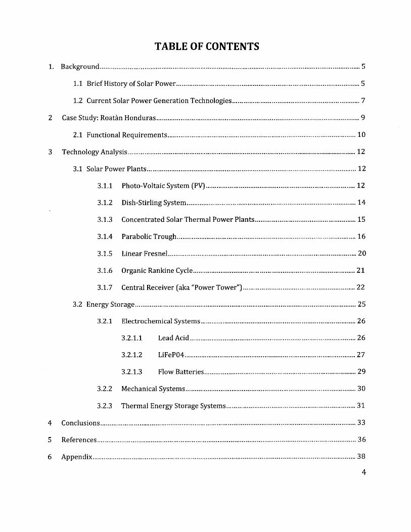
TABLE OF CONTENTS
1. Background............................................................................................................................................ 5
1.1 Brief History of Solar Pow er................................................................................................... 5
1.2 Current Solar Pow er Generation Technologies................................................................. 7
2 Case Study: Roatin Honduras......................................................................................... ....... 9
2.1 Functional Requirem ents................................................................................................. 10
3 Technology Analysis................................................................................................................................ 12
3.1 Solar Pow er Plants................................................................................................................ 12
3.1.1 Photo-Voltaic System (PV)............................................................................ 12
3.1.2 Dish-Stirling System ........................................................................................ 14
3.1.3 Concentrated Solar Therm al Pow er Plants................................................. 15
3.1.4 Parabolic Trough............................................................................................. 16
3.1.5 Linear Fresnel................................................................................................. 20
3.1.6 Organic Rankine Cycle................................................................................... 21
3.1.7 Central Receiver (aka "Pow er Tow er")........................................................ 22
3.2 Energy Storage....................................................................................................................... 25
3.2.1 Electrochem ical System s............................................................................... 26
3.2.1.1 Lead Acid...................................................................................... 26
3.2.1.2 LiFePO4........................................................................................ 27
3.2.1.3 Flow Batteries.................................................................................... 29
3.2.2 M echanical System s......................................................................................... 30
3.2.3 Therm al Energy Storage System s................................................................. 31
4 Conclusions.......................................................................................................................................... 33
5 References........................................................................................................................................... 36
6 Appendix............................................................................................................................................. 38
4

BACKGROUND
1.1 Brief History of Solar Power
Humans have made use of direct sunlight as an energy source for millennia. The
ancient Greeks in the 3rd Century BC used "burning mirrors" to light ceremonial torches,
the Romans used sunlight to heat bathhouses, and the Swiss scientist Horace de
Saussure used a solar oven to cook food during expeditions. However it was not until
the early 1980's that sunlight was harvested on a larger "utility" scale. In 1982 the
installation of a 1-megawatt capacity system in Hisperia California, was the first
installation of such a system on what can be considered a utility scale. The Hisperia
plant was developed by ARCO Solar and employed photovoltaic cells mounted on 108
separate dual-axis trackers. Despite ultimately being unable to make a profit and
eventually closing in 1994, the plant paved the way for the introduction of clean,
renewable solar power on a large scale. [1]
Shortly after the construction of the Hisperia plant in 1982 an industry consortium lead
by the U.S. Department of Energy constructed a 10-megawatt central-receiver
demonstration in plant in California, known as "Solar One". This plant established the
feasibility of solar-thermal electric or concentrating solar power systems (CSP). The
success of Solar One lead to the construction of larger solar thermal power plants
including a collection of plants known as the "Solar Energy Generating Systems" (SEGS),
this collection of power plants is located in the Mojave Desert has a combined
generating capacity of 354 MW. [2]
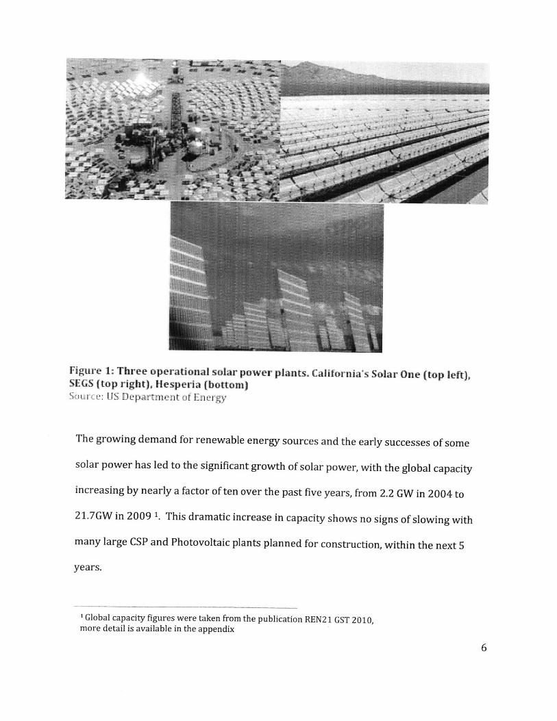
Figure 1: Three operational solar power plants. California's Solar One (top left),SEGS (top right), Hesperia (bottom)StIe: IlS Departnz1t or Energy
The growing demand for renewable energy sources and the early successes of some
solar power has led to the significant growth of solar power, with the global capacity
increasing by nearly a factor of ten over the past five years, from 2.2 GW in 2004 to
21.7GW in 2009 1. This dramatic increase in capacity shows no signs of slowing with
many large CSP and Photovoltaic plants planned for construction, within the next 5
years.
'Global capacity figures were taken from the publication REN21 GST 2010,more detail is available in the appendix
Global Solar Power Generation
2 LIQ 2005 S 2L)6Yea r
Figure: 2Source: REN21 GSR 2010
1.2 Current Solar Power Generation Technologies
There are a variety of methods that are currently being used to produce electricity from
sunlight on large scales. The simplest of these and the first to be implemented on a
large scale at the Hespera site was photovoltaics (PV). PV power plants convert
sunlight directly into electricity using solar cells. This direct conversion has the benefit
of being mechanically very simple and relatively low maintenance. Continuous
improvements in PV technology and new products such as thin-film cells from
Nanosolar promise to reduce the cost of solar power. Currently PV panels produce 96%
of the world's solar generated electricity. [3]

Concentrated solar power technologies (CSP), differ from PV arrays in that the sunlight
is used to heat a fluid that then spins a turbine to generate electricity, much like a coal
or nuclear power plant. These solar thermal plants are mechanically more complex
than PV plants but installations such as Solar One and SEGS have proven CSP to be an
effective means of utility scale electricity generation. The CSP plants in operation use a
variety of concentration methods including parabolic dish, parabolic trough, linear
fresnel and heliostats, as well as a variety of electricity generation methods including
stirling engines and steam turbines.
Figre : () P raholc Tough,(b) Linea r Fresnrel, (c) Pa'rabolc Dish,
(d) Centiral Reeie whIelott
RLI, i.
2. CASE STUDY: ROATAN HONDURAS
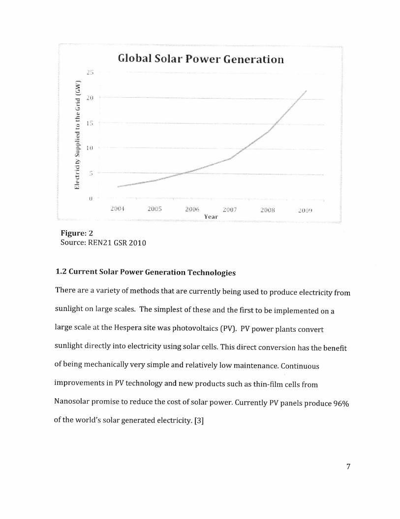
The island of RoatAn in Honduras is a member of a group of small islands known as the
"Bay Islands." Currently these islands including Roatan generate their own electricity
using a number of large diesel powered generators. The cost of this system is volatile
depending largely upon the cost of fuel, with monthly fuel bills costing between
$900,000 and $1,000,000, not including maintenance or repair costs. In addition to the
cost of fuel, an additional concern with the current power generation system is that of
pollution. The primary economic industry on the island is tourism and any damage to
the coral reefs and natural environment from a fuel leak or long-term use of the
generators would severely damage the island's economy. These concerns have led the
island to consider the installation of solar power plants in place of the diesel generators.
[4]
Figure 4: Satellite images of the Island of Roatin
2.1 Functional Requirements
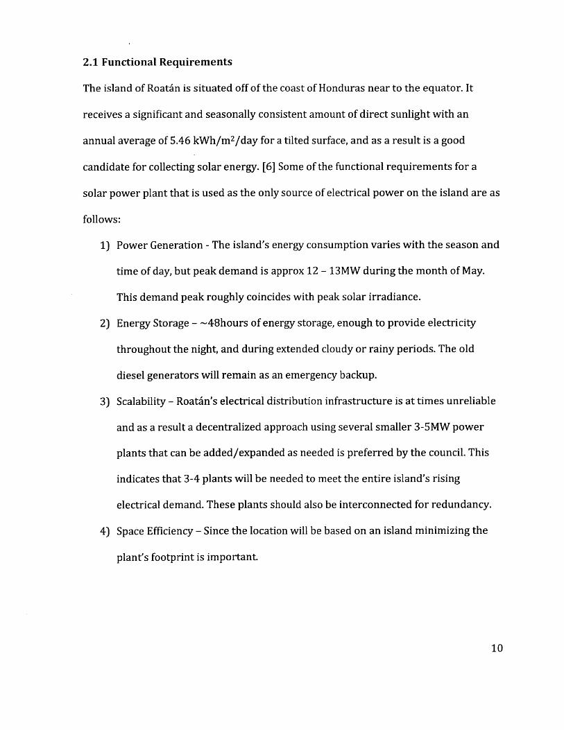
The island of Roatin is situated off of the coast of Honduras near to the equator. It
receives a significant and seasonally consistent amount of direct sunlight with an
annual average of 5.46 kWh/m 2/day for a tilted surface, and as a result is a good
candidate for collecting solar energy. [6] Some of the functional requirements for a
solar power plant that is used as the only source of electrical power on the island are as
follows:
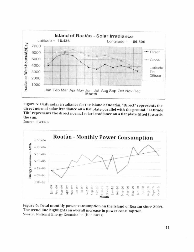
1) Power Generation - The island's energy consumption varies with the season and
time of day, but peak demand is approx 12 - 13MW during the month of May.
This demand peak roughly coincides with peak solar irradiance.
2) Energy Storage - -48hours of energy storage, enough to provide electricity
throughout the night, and during extended cloudy or rainy periods. The old
diesel generators will remain as an emergency backup.
3) Scalability - Roatin's electrical distribution infrastructure is at times unreliable
and as a result a decentralized approach using several smaller 3-5MW power
plants that can be added/expanded as needed is preferred by the council. This
indicates that 3-4 plants will be needed to meet the entire island's rising
electrical demand. These plants should also be interconnected for redundancy.
4) Space Efficiency - Since the location will be based on an island minimizing the
plant's footprint is important.
Island of Roatntn - Solar IrradianceLai tde= 16,436
7000
5000 y4000
30002000
1000
Longitude = -86,306
4 4
4 4
4 4*t ~~Thrt4't
t 44>44' 44' ~'j44
~ "'4 ''4"4 ' 4
CLA
0
r
0
Direct
(Global
LatitudeTitDiffuse
Aug Sep Oct Nov Dec
Figure 5: Daily solar irradiance for the Island of Roatin. "Direct" represents thedirect nornal solar irradiance on a flat plate parallel with the ground. "LatitudeTilt" represents the direct normal solar irradiance on a flat plate tilted towardsthe sun.Source: SWERA
x" rRoatan - Monthly Power Consumption
4E(4
.15E+4%T
/ ~ /
~-ty~ff4" IV1 \
V
t
3-
Xlnutl,
Figure 6: Total monthly power consumption on the Island ofRoatAn since 2009.The trend line highlights an overall increase in power consumption.So Lrcu: Natiional Energy Commrissimi [(Hndur as
Jan Feb Mar Apr May Jun JutMonth
3. Technology Analysis
3.1 Solar Power Plants
There are many potential designs that could be considered to meet these requirements,
some technologies to be considered are Photo-Voltaics (PV) and Concentrated Solar
Power (CSP) designs including, Dish-Stirling, Central Receiver, Parabolic Trough, and
Linear Fresnel.
3.1.1 Photo-Voltaic System (PV)
PV systems have the advantage of directly converting solar radiation into electricity;
this combines the collection and conversion step reducing the overall complexity of the
system. The primary large components needed for a PV power plant include:
Encapsulated PV cells, DC to AC solar inverters, and single axis stands to track the sun's
movement.
All of these components are readily available with many companies such as Suntech,
SunPower, and Nano Solar supplying silicon solar panels optimized for utility scale
applications. High-power, (>500 kW) DC to AC solar inverters are also marketed by a
number of companies including General Electric, Solectria, and Satcon. With many site
dependant variables, the overall cost of large scale PV system is variable and companies
are reluctant to comment on prices, but Beaumont Solar CO. an installer based in the
Boston area listed estimates for a turnkey (installed and grid ready) 5kW system as
$39,000 and a scaled up 100kW system as $700,000. [8] Assuming a linearly scaled
reduction in price due to economies of scale, this translates very roughly into $20.9

million for a 3MW system and $34.8 million for a 5MW PV plant. At least three of the
5MW plants would be needed to power the entire island at a total cost of approximately
$104 million.
Figure 7: Photo of a large scale PV power plant.Se: Departmenit f Energy (United Stateis)
PV solar power plants have the advantage of being mechanically quite simple with few
moving parts and little maintenance and upkeep required. They also benefit from being
very modular; expansion can easily be accomplished by simply adding more panels and
inverters. The downsides to this technology are that PV panels are still expensive when
compared to other technologies, and the lack of an energy storing medium means that
for large-scale off grid applications such as the island of Roatan expensive energy
storage methods such as batteries or mechanical flywheels must be used and the cost of
which would have to be added into the cost of the PV system.
3.1.2 Dish-Stirling System
Dish-Stirling systems are a form of concentrated solar power where a parabolic dish is
used to concentrate sunlight onto a small absorber/heat exchanger. The energy
absorbed by this heat exchanger is then used to run a stirling engine which powers a
generator producing electricity for the electrical grid. Such a system is already being
produced and installed by companies such as Stirling Energy Systems (SES). SES
produces a 25kW solar dish stirling concentrating solar power system that has already
been installed into a 1.5MW Power Plant In Maricopa County Arizona. Even though SES
is not releasing cost figures a company representative claims that the installation's cost
per kilowatt-hour over the plant's expected lifetime is competitive with California's
Market Price Referent (MPR). [9] This means that overall lifetime cost of the electricity
from the plant should be in the range of $0.10 - $0.12 per kWh, or roughly equivalent to
the cost of owning and operating a new base load combined cycle gas turbine (CCGT)
power plant as determined by the state of California. [10]
Dish-Stirling systems such as those supplied by SES take advantage of the high
thermodynamic efficiency of the Stirling cycle with SES boasting the highest solar
energy to grid peak conversion efficiency of any solar technology at 31.25%2. The
compactness and scalability of the dish-stirling unit is also an advantage. With
expansion the of an existing power plant consisting of simply installing more units. The
disadvantages however include increased system complexity compared to a PV power
plant and similar to the PV power plant, an installation on the island of RoatA'n
z Peak conversion efficiency represents the conversion of direct normal solarirradiance into electrical output, as claimed by Stirling Energy Systems. 1 A
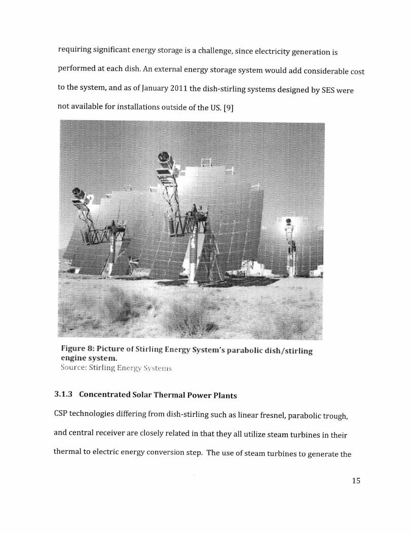
requiring significant energy storage is a challenge, since electricity generation is
performed at each dish. An external energy storage system would add considerable cost
to the system, and as of January 2011 the dish-stirling systems designed by SES were
not available for installations outside of the US. [9]
Figure 8: Picture of Stirling Energy System's parabolic dish/stirlingengine system.Source: Stirling Enelrgy ystera
3.1.3 Concentrated Solar Thermal Power Plants
CSP technologies differing from dish-stirling such as linear fresnel, parabolic trough,
and central receiver are closely related in that they all utilize steam turbines in their
thermal to electric energy conversion step. The use of steam turbines to generate the
electricity in power plants is common, with Nuclear, Coal, and Gas power plants all
using similar thermodynamic processes to generate the electricity. The primary
difference between each of these plants, and CSP solar plants is simply the heat source.
The common use of the steam turbine in power generation means that the technology
has been well optimized, and is well understood. CSP plants using steam turbines also
benefit significantly from economies of scale with the cost per kW decreasing as the size
of the plant increases. Centralized electrical generation is also an advantage where
large-scale energy storage is needed. Due to the thermal energy being pumped through
a single stream to power the turbines, diverting and storing that energy, as heat, is
conceivably cheaper and simpler than with a multitude of smaller storage units. Some
of the drawbacks to a plant using centralized steam turbine are the lack of easy
scalability; increasing capacity may mean replacing expensive components such as the
turbines, instead of simply adding more units. Despite of their many similarities in how
they produce electricity, CSP plants differ primarily in how they harvest energy from
the sun.
3.1.4 Parabolic Trough
Trough collectors are still the most proven design for CSP power plants. With the
installation of SEGS I in 1984 and later with 5 more SEGS installations the technology
has been proven reliable and effective. With a long parabolic trough focusing light onto
a long, vacuum insulated receiving tube, the support structures needed for the trough
are smaller, less complicated, and a single long trough can cover a larger illuminated

area than other forms of solar concentrators. Tracking of the sun can also be
accomplished using a single axis.
Some drawbacks to this design are that the mirrors shaped as a parabolic trough can be
difficult/expensive to manufacture and install, and the heat transfer fluid receiving the
thermal energy must travel through a lot of piping before being used to generate steam.
This adds to systemic losses with more power needed to pump fluids, thermal losses
through the insulation, and more costs associated with the vacuum insulated tubes used
to absorb the solar energy. Trough CSP plants also have a relatively low concentration
ratio when compared to other CSP designs. This translates to a lower fluid working
temperature (typically -350degrees centigrade) and the use of the Rankine cycle with
thermal efficiencies of -40%. [12]
Figure 9: Picture of the parabolic collectors at an SEGS installationSurce: De artn iet o t J g (i Oted Stat es

Due to many different factors, the costs associated with parabolic trough concentrators
can very significantly depending on the systems and installation sites used. Studies
conducted for the World Bank 3 have shown an estimated total plant cost of $2971 per
kW of total plant output for a 30 MW Rankine cycle trough concentrated solar power
plant, installed in a developing country. These numbers are broken down further in
figure 10.
CarFapa~1ern(Wukeou~I 2it 1ad4A
ane t Puy 2? 1 STP (1 TtA
Aii re1-F-h-ted
Lae W1cr i ) 1
St~Aw nc Fox534 318 1402
STu rL Sypeminau 242 234 13
L3 T 1B hER
Figure 10: Estimated Current Costs of Parabholic Trough CSP PLants (in $/kWof total plant routput)Svturce: Enecrmo~dali En gineering Ltd) Mairbek Reso urce Consuwltants Lti.
3 h World Bank hired Enermodal Engineering Ltd./Marbek ResourceConsultants Ltd. To conduct the study to evaluate current and future costreductions in solar thermal power technologies.

Figure 11: Estimates of Rankine-Cycle Solar Plant Specific CostSource: Enermodal Engineering Ltd.Ma Resource Consultants Ltd.
Figures 10 and 11 show how the cost of a parabolic trough CSP power plant can vary
significantly depending upon the plant's size and location. Extrapolating from the data
given here it and assuming an exponential trend in cost per kW as the plant size
decreases, it can be estimated that a small-scale parabolic trough solar plant using a
steam turbine would cost approximately $18 million for a 3MW plant, $26 million for a
5 MW plant, and $55 million for a single 15 MW plant. This analysis shows the benefit of
scale with the cost per kW decreasing significantly with size. The 3 MW plant costs
$6167 per kW, the 5 MW $5258 per kW, and the 15 MW plant $3709 per kW. For 15
9
9
9
MW of each plant size, this translates into a total cost for the island of $93 million, $79
million, and $55 million respectively.
3.1.5 Linear Fresnel
Linear Fresnel collectors function in much the same way as the parabolic trough
collectors except that instead of using a one large curved mirror to concentrate onto a
receiving pipe, many smaller, flat or slightly curved, mirrors reflect sunlight onto a
receiving pipe, or a smaller secondary parabolic reflector which then focuses the
sunlight onto an insulated pipe. The proposed benefits are that the flatter mirrors can
be cheaper to manufacture, and can be more tightly packed together allowing for a
more efficient use of ground area as well as a higher concentration ratio.
The disadvantages to a system of this type are that the greater number of reflectors
increases the complexity of the system, with each facet of the reflectors having to track
the sun differently in order to focus onto the pipe or secondary reflector, and the need
of a secondary reflector to help concentrate the sunlight decreases the optical efficiency
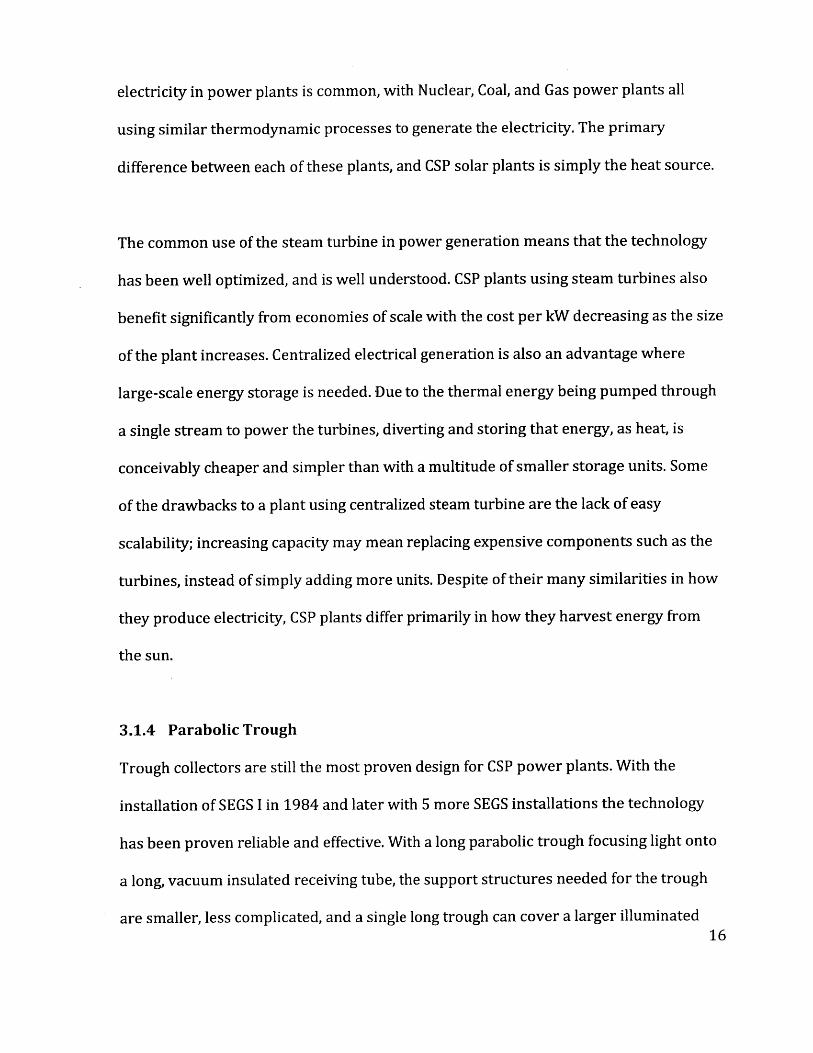
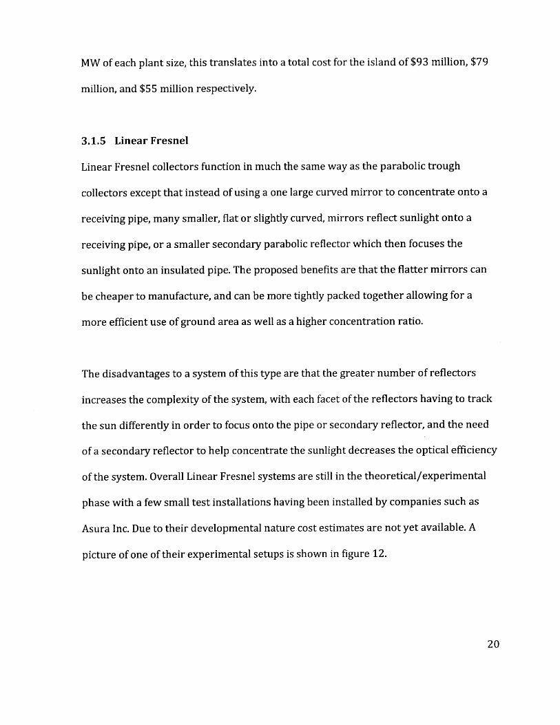
of the system. Overall Linear Fresnel systems are still in the theoretical/experimental
phase with a few small test installations having been installed by companies such as
Asura Inc. Due to their developmental nature cost estimates are not yet available. A
picture of one of their experimental setups is shown in figure 12.
Figure 12: Linear Fresnel Solar CollectorsSource: Asura Inc.
3.1.6 Organic Rankine Cycle
Another technology that may have application for Roatan but has not been used for
solar power is that of organic rankine cycle turbines. These are turbines that are similar
in principle to the steam turbines used in the current solar power plants, but instead of
using water/steam as the working fluid, organic (hydrocarbon) compounds are used.
The benefit is that the system can operate at lower temperatures and pressures. This
translates into lower capital costs since less costly piping, valves, and turbine
components can be used. The disadvantage is that the thermal efficiency decreases
slightly. Organic rankine cycle systems are commonly used in geothermal systems
where temperatures and power outputs are lower. No currently operational solar

thermal power plants use this system to produce electricity, but it may have a cost
advantage for the 3-5MW sized power plants that is preferred for this application.
Further analysis and study is needed to confirm this but is it likely that at the 15MW
scale the cost benefits will be outweighed the losses in efficiency. [4]
3.1.7 Central Receiver (aka "Power Tower")
The central receiver, also known as "Power Tower," has also seen some limited success
with implementation at California's experimental Solar One and a new 11MW
commercial installation in Seville Spain. The central receiver design consists of a field of
mirrors mounted to individual heliostats designed to reflect the sunlight onto a central
receiver placed near the top of a large central tower. By reflecting onto a single central
point, the thermal and pumping losses of the fresnel and trough designs are reduced,
and higher levels of concentration are achievable. The main difficulty associated with
this concept is that the heliostats are very costly, they must very precisely track the sun
through two axis to maintain focus on the tower, and dust or other airborne particles
can reduce the optical efficiency of the heliostats reflecting light onto the receiver
tower.
The tower is the structure that houses the receiving absorber and transmits the thermal
energy to the rest of the plant's components. The thermal tower plants currently in
operation convert their thermal energy into electrical energy using the same rankine
cycle that the parabolic trough plants use. However, the higher concentration ratios
achievable with the thermal towers allow for a higher temperature in the heat transfer22

fluid (up to 1000*C instead of 350'C). This helps to increase the plant's solar to
electrical energy conversion efficiency with peak efficiencies reaching up to 23-25%
(compared to 20% in parabolic trough plants). [14] These higher temperatures might
also allow for an even greater increase in plant efficiency if the hot gas can first be used
to power a brayton cycle turbine before the "waste heat" is used to create steam and
run a rankine cycle turbine. Such a combined cycle plant, (similar in concept to current
combined cycle gas power), is still in the experimental phase but a small combined
cycle plant is currently being build by Abengoa Solar at the Seville site for testing.
The cost of a small thermal tower designed for the island of Roatan is difficult to
estimate due to the small number of such plants in operation. However, the World Bank
cost study4 lists the cost of building a 100MW central receiver power plant as $3,270
and 19% lower at $2,660 in developing countries. The break down of the estimated
costs involved in a 30MW central receiver power plant is shown in Figure 14.
Extrapolating from these two estimates we can roughly estimate that the installation
costs of a central receiver solar thermal power plant using the rankine cycle with the
capacities of 3MW, 5MW, and 15MW are $4,806 per kW, $4762 per kW, and $4541 per
kW respectively. For 15 MW of each plant size, this translates into total costs of, $14
4The World Bahk hired Enermodal Engineering Ltd./Marbek Resource Consultants Ltd. Toconduct the study to evaluate current and future cost reductions in solar thermal powertechnologies.

million, $24 million, and $68 million respectively. Using this method to calculate the
costs of an 11MW plant gives an estimate that is within 5% of the actual estimated costs
for the PS10 plant in Seville Spains. It should also be noted that the estimates include
the cost of approximately 6.5 hours of thermal energy storage.
Figure 13: Photo of the PS10 installation in Seville Spain.Sour'ce: Abengo.a So:lr
s I estimated the installation cost of an 11MW central receiver plant to be $50 million; actualcost was 35 million euros [15]. Using the conversion rate of 1.36 euro to dollar, from the end of2004 (when the plant was completed), gives an estimated error of 4.8%.
24

SiteWorn117117ri 4H tsI t! 27 I267
Hi & F sin soLe' 177 1ff
P:Twvnr Blexck/ Da;irefc f Plan t 933 450
Contmgr :y 64 6
_Tota; J) part 49Y) 33
Eksnco L ir D wn :.ng Catens r744 .
To 42093689
Figure 14; Break down of estimated costs for a 20 MW central receivingsolar thermal power plant.S u e:1 E Ine VIn a I E ci, i: Ltd. I .:i I R 1'rA I, C n 'ul sa L td.
3.2 Energy Storage
Large-scale multi-day energy storage, as is needed for the Island or Roatan, is a design
challenge that has not been addressed within national power grids. Most power grids
meet demand primarily by throttling fossil fuel powered plants to meet demand and
using some short term energy storage methods to help smooth fluctuations in demand.
Examples of these short-term energy storage methods include the large Ni-Ca battery
banks in Fairbanks Alaska that are designed to supply 27MW for 15 minutes and the
practice of pumping water into a reservoir to be used during off peak hours.
For solar power to be used as the only source of electrical power generation the storage
capacity of a solar power plant must be very large relative to its generation capacity to
continue to output power throughout the night and during extended periods of cloudy
or poor weather. There are countless different technologies that can be used to store
large amounts of energy but for this evaluation, a few of the most promising will be
evaluated. Two forms for large-scale energy storage that might pair well with a
decentralized PV or dish-stirling solar plant on the island of Roathn are mechanical
(flywheel) and electro-chemical (battery) storage.
3.2.1 Electrochemical Systems
3.2.1.1 Lead Acid
There are a number of battery chemistries that might be used as an energy buffer to
supply power throughout the night and during periods of low solar insulation. The most
common of which are lead acid batteries. Commonly used in car batteries, the cost of
energy storage in lead acid batteries currently hovers at around $150 per kWh 6. For a
first order estimate the Island of Roath'n would need to store at least 12 hours worth of
electricity to power the island day and night off of solar energy alone. On average this
works out to storing about 82MWh, at a price of approx $12.3 million.
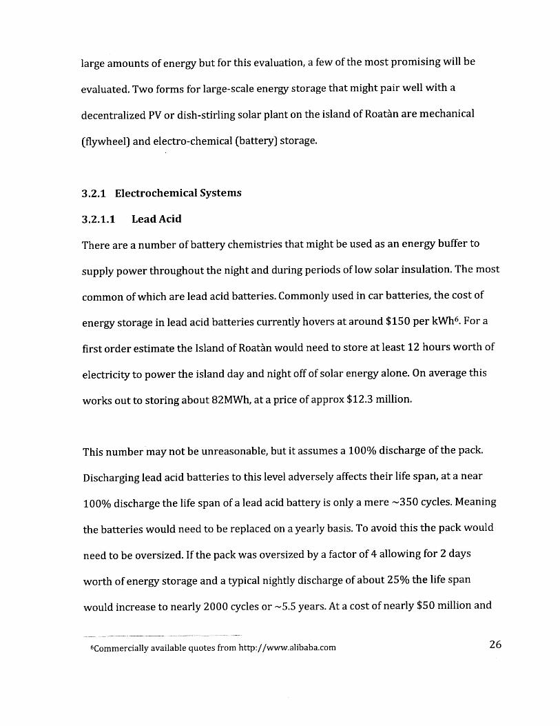
This number may not be unreasonable, but it assumes a 100% discharge of the pack.
Discharging lead acid batteries to this level adversely affects their life span, at a near
100% discharge the life span of a lead acid battery is only a mere -350 cycles. Meaning
the batteries would need to be replaced on a yearly basis. To avoid this the pack would
need to be oversized. If the pack was oversized by a factor of 4 allowing for 2 days
worth of energy storage and a typical nightly discharge of about 25% the life span
would increase to nearly 2000 cycles or -5.5 years. At a cost of nearly $50 million and
6Commercially available quotes from http://www.alibaba.com 26
needing to be replaced every approximately 5.5 years (which works out to about $272
million if the plant has a 30 year lifespan) lead acid batteries are not an attractive
means of utility scale energy storage when relatively deep discharge cycles are needed.
10000
5000
2000
S1000
5003
200
1000 10 20 30 40 50 60 70 80 90 100
Depth of Disc#hge
Figure 15: Cycle life of lead acid batteries vs. depth of dischargeSource: http://w ww windsun.com/Batteries/
3.2.1.2 LiFePO4
A second battery chemistry that might be better suited to this application is that of
Lithium Ion batteries, specifically LiFePO4. Lithium Iron Phosphate batteries can have
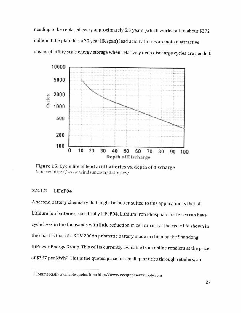
cycle lives in the thousands with little reduction in cell capacity. The cycle life shown in
the chart is that of a 3.2V 200Ah prismatic battery made in china by the Shandong
HiPower Energy Group. This cell is currently available from online retailers at the price
of $367 per kWh 7. This is the quoted price for small quantities through retailers; an
7Commercially available quotes from http://www.evequipmentsupply.com
order of the quantity needed for this application would almost certainly come with a
price reduction. Assuming that the price is $300 per kWh, and with the same 2 day
capacity 25% nightly discharge, a pack made from these cells would cost $98 million.
High cycle life data beyond 1000 - 2000 cycles on LiFePO4 cells is very limited, but
assuming a roughly linear depreciation in capacity, the cells should have a life span of
nearly 15000 cycles before being unable to store enough energy to power the entire
island through a 12 hour period. This estimate is also conservative since the pack is
initially only being discharged to 25% depth of discharge instead of the 100% depth of
discharge used in the test. This translates into a lifespan of nearly 40 years of daily
charge/discharge cycles, bringing the per year cost of the batteries to $2.3 million.
Charge:2 03C Tio 3J V 7 CCDJ
Figu re 1,6- Cce fife of a 200Ah11 LiFePO4 prismaltic cell baL'tte'tY..Source: 'Shangdon H -Fwe Enrg Grou p--F

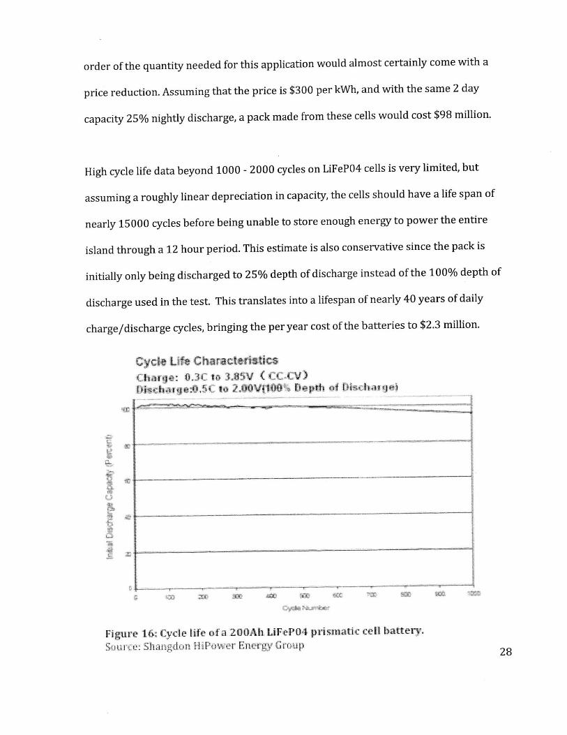
3.2.1.3 Flow Batteries
Flow batteries are a means of energy storage similar in principle to lead acid and
lithium ion batteries, with the exception that their chemical reactants are stored in
separate tanks and pumped through a separate electrochemical cell where the chemical
reaction takes place allowing the release of electricity. The external storage of the
reactants allows for great economies of scale, the tanks can simply be sized up for
greater storage capacity, or similarly the reactive cell can be sized up for greater power
output. The physical separation of the reactants also prevents self-discharge over time
and aids in increasing the life of the battery. There are a number of companies building
and marketing utility scale flow battery systems including the Premium Power
Corporation and the ZBB Energy Corporation.
Currently the flow battery providing the most economical means of large-scale energy
storage is that of Zinc-Bromide (ZnBr) Flow Batteries. ZnBr flow batteries are relatively
inexpensive and can provide energy storage at the cost of approximately $230 per kWh
and $300 per kW [16], while having a no limits to the number of cycles the system can
withstand during its estimated 30 year lifetime. These estimates include estimated
costs for balance of the system and accessory components needed for their operation.
Additionally, not having a limited cycle life, and the decoupling of the reactant storage
and the electrochemical cell, allows the system to be sized appropriately for the
demand at hand without the need for extensive reserve capacities. Using these
estimates a system capable of supplying the island with enough electricity for an
Figure 17: Example diagram of a ZnBr Flow battery system.Siour-ce: h-ttp://www~zbbeniergy.om. )/
average two-day period at a peak demand of 15MW8 would cost approximately $80
million.
3.2.2 Mechanical Systems
Mechanical energy storage systems function by storing energy in the form of kinetic
(flywheels) or potential energy (pumped hydro). The island of Roatan lacks any large
mountains or water reservoirs and as a result the only mechanical system that is
technically feasible for the island is that of mechanical flywheels. Flywheels are
commonly and very effectively used as a form of short-term energy storage and grid
support. Companies such as the Beacon Power Corporation, supply and support farms
that supply utility scale short-term utility scale energy storage, but high capital costs
8 15MW is an over estimate, allowing for future growth and providing power during peak demand.A system primarily used to provide power at night could get by with significantly less.
and energy losses associated with longer-term energy storage (-24hrs) [11] with these
systems means that they are not a viable option for the Island of Roatan.
3.2.3 Thermal Energy Storage Systems
Unlike, PV or Dish-Stirling power plants, CSP power plants operate using a centralized
rankine cycle generator. In these systems all of the thermal energy collected by the
plant must be transferred to the steam turbine using a heat transfer fluid. This has the
potential to provide a very inexpensive means of energy storage. By simply diverting
the hot fluid and storing it in thermally insulated tanks the energy can be stored in the
form of heat with minimal investment in storage systems. Thermal energy storage has
already been tested at a number of solar power plants including the SEGS locations and
the newer power plants in Seville Spain.
The SEGS and Seville systems utilized a two-tank system where cold fluid is stored
within one tank before being pumped through the collector array and being stored
inside a different insulated tank until it was needed to generate steam. These systems
are capable of providing enough thermal energy storage for two hours of plant
operation in the SEGS system and up to six hours of operation at the Seville
installations. Their success has proven the feasibility of such concepts and
demonstrated a thermal efficiency of greater than 99%. [17] The integration of thermal
storage is relatively straightforward with the energy capacity being dependant upon the
tank size, fluid heat capacitance, and fluid temperature, with higher temperatures
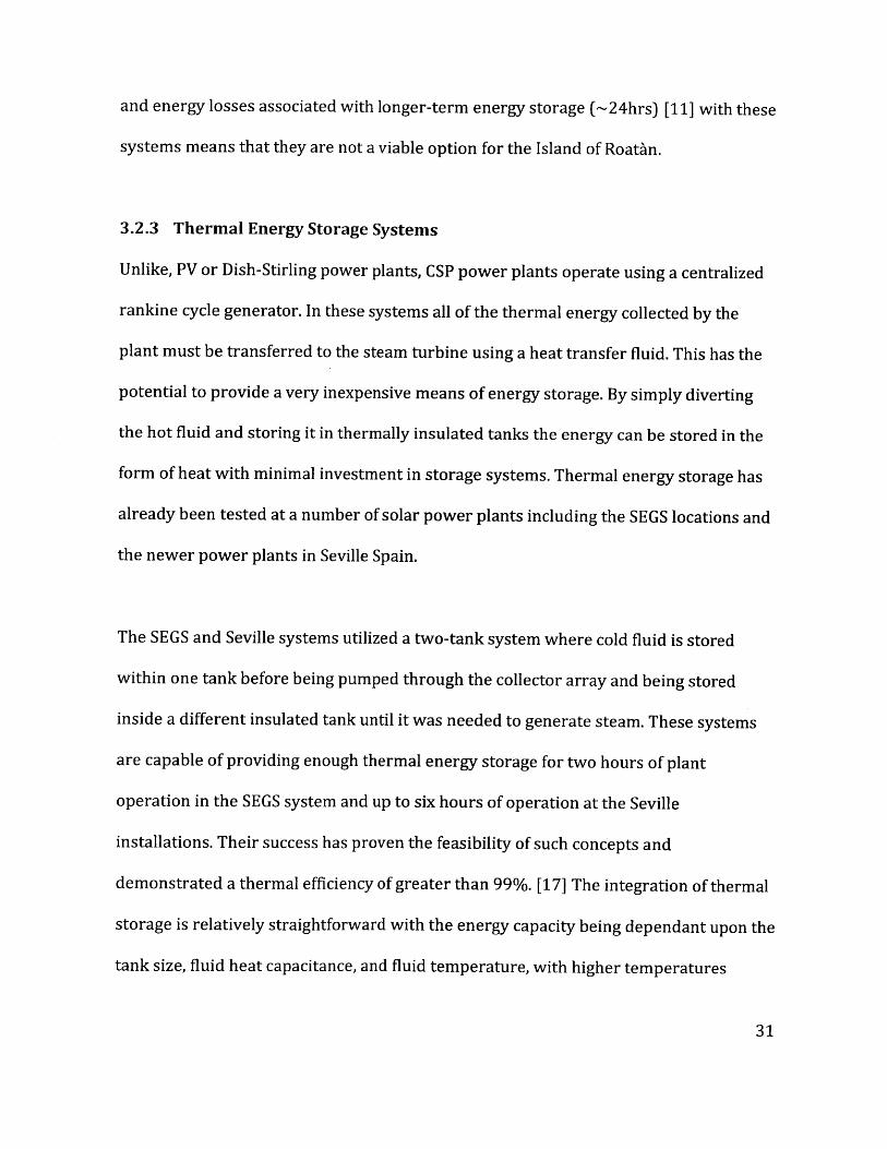
giving a greater energy capacity for a given tank size, but often requiring a more
expensive thermal storage fluid that can withstand the sustained higher temperatures.
Figure 18: Picture of the two molten salt storage tanks at the Andasolsolar power plant.Source: Scientific American Magazine
The recently installed Andasol solar power station, which went online in 2009, is a
50MW parabolic trough solar power plant that was designed to utilize a twin tank
thermal energy storage system. It uses molten salt to store up to 1,010MWht of thermal
energy. At the time of construction it cost roughly $50 per kilowatt-hour to install,
according to NREL's Glatzmaier. [7] Using this estimate and a predicted steam to
electricity conversion efficiency of 37%,9 the expected cost of a thermal storage system
9 37% is the approximate steam to energy conversion efficiency experienced by the SEGS SolarParabolic Trough power plants. [17]

being added onto a parabolic trough CSP plant with enough capacity to power RoatAn
for two average days would cost around $13million, and store 267 MWht of energy.
4. Conclusions
A summary of the cost estimates for all of the currently commercially available
technologies solar power generation technologies is shown in Figures 19 and 20.
Cost Estimates $ Millions)Power Plant Type 3MW 5MW 15MWPhoto Voltaics 20.9 34.8 70Parabolic Trough 18 26 55Central Receiver 14 24 68
Cost of 2 DayEnergy Storage Type Capacity Notes:Lead 272 30 year lifespanLiFePO4 98 40 year lifespanZnBr 80 30 year lifespanThermal (2 Tank 13 N/AMolten Salt) I
Figure 19: Chart of estimated installation costs for commercially availablesolar power generation technologies, and large-scale energy storage.
This first order analysis shows that there is a significant difference in the cost of
implementing the varyous energy storage methods. For the use of photovoltaics,
ZnBr flow batteries are potentially the best means of storing enough energy to run
the Island off of solar power alone. Especially since the number used to calculate the
costs of the LiFePO4 cells does not include any balance of system or structural costs
while the numbers quoted for the ZnBr system do.

The significantly lower cost of the thermal energy storage system, reletive to the
other systems, indicates that regardless of other factors which may have been
excluded in this analysis, a concentrated thermal power system is the most cost
effective method to choose to generate power for Roath'n. All of the technologies
evaluated here are technically capable of meeting the functional requirements for
the island, and when connected to a large established grid it seems that on the small
to medium sized scales evaluated here, that the three technologies are on a
relatively even playing field. The 3-15MW power range is very small when
compared to most operational parabolic trough power plants, which are most
economical in the 100's of MWs. For RoatA'n's application it is the large amount of
energy storage needed that makes the thermal power plants the most feasible
option.
Estimated Installation Costs100
9080
70 ~ 70 Parabolic Trougho 60
~so ~Central Receiver40
0, PhotovoltaicS30
o 20100
3MW 5MW 15MW
Individual Power Plant Outputs
Figure 20: Comparison of the three commercial technologies evaluated.
The results of this analysis show that the design should continue with one of the
solar thermal concepts. Since, both are relatively close in terms of costs a more
detailed analysis of component specific costs will need to be conducted. It may also
be beneficial to include some of the newer experimental components such as using
linear fresnel reflectors, organic rankine cycle turbines, and potentially new
thermal storage ideas such as single-tank thermocline systems. The experimental
components present opportunities for increased efficiencies and reduced costs but
incorperate greater risks and may require a partnership with the companies
exploring these technologies.
Another insight to take away from this analysis is that for thermal solar power
plants capacity matters significantly, with the 15MW plants costing significantly
less per kW than multiple 3 or 5MW plants. This indicates that, if the finances can
be raised and Roatan's final goal is to be completely solar powered, it would be
most beneficial to use a centralized 15MW plant instead of several dispersed plants
and invest the saved money into improving the grid. This will also save costs in
yearly operations and maintinence bills, as more parts and operators will be needed
to operate and service multiple small plants as opposed to a single larger
installation.

5. References
[1] "Deep Cycle Battery FAQ." SolarElectricPower Componentsand SolarPanels.Northern Arizona
Wind & Sun, 2009. Web. 10 Dec 2010. <http://www.windsun.com/Batteries/BatteryFAQ.htm>.
[2] United States. History of Solar., Web. 1 Jan 2011. <wwwl.eere.energy.gov/solar/pdfs>.
[3] REN21. 2010. Renewables 2010 Global Status Report (Paris: REN21 Secretariat). Copyright
@ 2010 Deutsche Gesellschaft fur Technische Zusammenarbeit (GTZ) GmbH.
[4] Hassani, Vahab, and Henry Price. "Modular Trough Power Plants." Proceedings of Solar
Forum 2001 Solar Energy: The Power to Choose. Washington, DC, 2001. PDF.
[5] "Solar Thermal Power Plants." Renewable Energy World Jun. 2003: 109-13. Web. 22 Dec
2010. <http://www.volker-quaschning.de/articles/fundamentals2/index.php>.
6) U.S. National Renewable Energy Laboratory (NREL), . "Solar: annual average latitude tilt map
at 40km resolution for Central America from NREL." SWERA 2003-Dec-11. n. pag. Database. 23
Nov 2010.
[7] Biello, David. "How to Use Solar Energy at Night." Scientific American 18 Feb 2009: n. pag.
Web. 5 Jan 2011. <http://www.scientificamerican.com/article.cfm?id=how-to-use-solar-
energy-at-night>.
[8] "Solar Fact Sheet." Beaumont Solar Company. N.p., n.d. Web. 30 Dec 2010.
<http://www.beaumontsolarco.com/solar-energy-fact-sheet.asp>.
9) "Technology." Stirling Energy Systems. Stirling Energy Systems, 2010. Web. 08 Dec. 2010.
<http://www.stirlingenergy.com/technology.htm>.
[10] "Feed-in Tariff Price." California Public Utilities Commission. Public Utilities Commission, 17
Nov 2010. Web. 20 Dec 2010. <http://www.cpuc.ca.gov/PUC/energy/Renewables/Feed-
in+Tariff+Price.htm>.
[11] "About Flywheel Energy Storage." Beacon Power. N.p., 17 Nov 2010. Web. 2010.
<http://www.beaconpower.com/products/about-flywheels.asp>.
[12] "Parabolic Trough Technology." TroughNet. National Renewable Energy Laboratory, 01
Jun. 2010. Web. 10 Dec 2010. <tp://www.nrel.gov/csp/troughnet>.
[13] "Solar Steam Generator Overview." Asura. Asura, 2010. Web. 15 Dec 2010.
<http://www.ausra.com/technology/applications.html>.
14) "PS10: The first commercial tower of the world." Soldcar Platform. Abengoa Solar, 2008.
Web. 11 Oct. 2010. <http://www.abengoasolar.com/corp/web/en/index.html>.
[15] "PS10." Solar Power and Chemical Energy Systems. Solar Paces, n.d. Web. 1 Dec 2010.
<http://www.solarpaces.org/Tasks/Taskl/ps1O.htm>.
[16] Kluza, J.J. (2009). status of grid scale energy storage and strategies for accelerating cost
effective deployment. Informally published manuscript, System Design and Management
Program, Massachusett Institute of Technology, Cambridge, MA. Retrieved from
http://hdl.handle.net/1721.1/5521017)
[17] Sargent & Lundy LLC Consulting Group. Assessment of Parabolic Trough and Power Tower
Solar Technology Cost and Performance Forecasts. Golden, CO : National Renewable Energy
Laboratory, NREL/SR-550-34440. NREL/SR-550-34440.
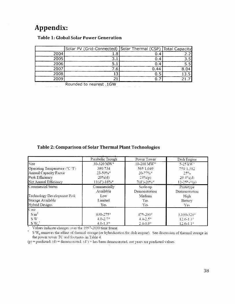
Appendix:Table 1: Global Solar Power Generation
Solar PV (Grid-Connected) Solar Thermal (CSP) Total Capacity2004 1.8 0.4 2.22005 3.1 0.4 3.52006 5.1 0.4 5.52007 7.6 0.44 8.042008 13 0.5 13.52009 21 0.7 21.7
Rounded to nearest ,1GW
Table 2: Comparison of Solar Thermal Plant Technologies
Parabolic Trough Power Tower Dish EnnieSize 30-320 MW* 10-200 MW* 5-25 kW*Operating Temperature (*C 'F) 390 734 565 1.049 750 1.382Annual Capacity Factor 23-50%* 20-7% 25Peak Efficiency 20%(d) 2 3 %(p) 294%(dNet Annual Efficiencv 11 (d')-16%* 7(d')-20%* 12-25o*(p)Commercial Status Commercially Scale-up Prototype
Available Demonstration DemonstrationTechnology Development Risk Low Medium HighStorage Available Limited Yes BattervHybrid Designs Yes Yes YesCost
S mn' 630-275* 475-200* 3.10-320*$ W 4.0-27 4.4-2.5* 12.6-1 3$ W~ 4.0-1.3* 2.4-.9 12.6-1 1Values indicate chanies over the 1997-2030 time frame.S WV, removes the effect of thermal storage (or hybridization for dish engine). See discussion of thermal storage inthe power tower TC and footnotes in Table 4.
(p)= predicted; (d)= demonstrated: (d'= has been demonstrated, out years are predicted values
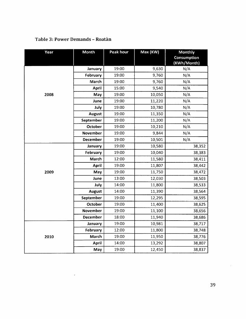
Table 3: Power Demands - Roatan
January 19:00 9,630 N/A
February 19:00 9,760 N/A
March 19:00 9,760 N/A
April 15:00 9,540 N/A
May 19:00 10,050 N/A
June 19:00 11,220 N/A
July 19:00 10,780 N/A
August 19:00 11,350 N/A
September 19:00 11,200 N/A
October 19:00 10,210 N/A
November 19:00 9,844 N/A
December
January
19:00
19:00
10,501
10,580
N/A
38,352
February 19:00 10,040 38,383
March 12:00 11,580 38,411
April 19:00 11,807 38,442
May 19:00 11,750 38,472
June 13:00 12,030 38,503
July 14:00 11,800 38,533
August 14:00 11,390 38,564
September 19:00 12,295 38,595
October 19:00 11,400 38,625
November 19:00 11,100 38,656
December 18:00 11,940 38,686
January 19:00 10,981 38,717
February 12:00 11,800 38,748
2010 March 19:00 11,950 38,776
April 14:00 13,292 38,807
May 19:00 12,450 38,837
2008
2009