assessment of bicyclist head injury under - ircobi · manager, and q. allinne and a. gallego are...
TRANSCRIPT
Abstract Although cycling may be attractive for both economic and environmental reasons, cyclists are
extremely vulnerable road users and subjected to falls or collisions with cars. Therefore, wearing a helmet is of
crucial and vital importance considering the high percentage of head injuries in cyclists. The present research
attempts to understand the degree of protection offered by a commercial bicycle helmet under realistic oblique
impact conditions. Experimental research was carried out on an existing helmet to perform 2 oblique impact
situations at ambient temperature. In parallel, the helmet was digitized and meshed to produce a finite element
model (FEM) that was implemented under the PamCrash® crash code. Coupled to a 50th percentile Hybrid III
dummy head FEM, the experimental tests were numerically reproduced in order to provide a validation of the
helmet model under tangential impact conditions. Then, coupled to a detailed human head model in order to
assess the head injury risk under tangential impact, results showed that even if frontal oblique impacts are more
critical than lateral ones, computed injury risks are acceptable for a realistic head impact condition as extracted
from bicyclist accident analysis.
Keywords: bicycle helmet, brain injuries, head modeling, helmet modeling, oblique impacts
I. INTRODUCTION
Cycling represents one of the most popular recreational sports, but also one of the main transportation means all over the world and more specifically in urban areas. As reported by the United Nations in 2003 [1], road traffic injuries caused the death of more than one million humans in the year 2000, representing the ninth highest cause of death worldwide. Many previous studies have outlined the effectiveness of wearing bicycle helmets [2‐3] and also the possibility of the improvement of currently used helmet design [3]. According to Belgian statistics published in a recent survey [6], 7.3% of bicyclists used the bike as their main method of transportation to work and 19.2% to school. In 2000, 9.8% of all road accidents and 9.1% of road traffic deaths on Belgian public roads were represented by pedal cyclists. Besides, according to a survey published in 2012 concerning road accidents in France [7], 65% of the 4567 bicycle accidents in 2011 were collisions with cars whereas only 4% were collisions with heavy trucks.
The head represents the most vulnerable part of the human body and one of the most important to be protected. Between 21 to 61% of the victims of bicycle accidents seeking medical care have a head injury as reported by Collins et al. [8] and Eilert‐Petersson & Schelp [9]. The medical care required by this large number of victims also implies high costs both economic and societal. Bicycling dramatically leads to increased numbers of fatalities due to head injuries which represent the cause of death in 69–93% of fatal accidents according to Oström et al. [10]. Therefore, wearing a helmet is of crucial and vital importance considering this high percentage of head trauma in cyclists.
The bicycle helmet protects the head against impacts by reducing the impact energy that is transmitted to the head through energy absorption and dissipation through elastic and plastic deformation of its components (external shell and foam liner), and by increasing the area over which the impact is distributed. Nonetheless, the EN 1078 standard [11] considered in Europe to homologate bicycle helmets does not take into account any effects of a tangential component since only normal impacts are performed. More realistic would be to test helmets for impact similar to the most commonly observed impacts in real life bicycle accidents. Otte et al. [12] showed that oblique impacts, with a significant tangential force applied on the helmet, are more common than radial (normal) impacts in crashes. The authors also found that the frontal regions and the sides of the helmets
G. Milne is PhD student, C. Deck (tel: +33 (0) 3 68 85 29 40, fax: +33(0) 3 68 85 29 36, email: [email protected]) and N. Bourdet are researchers, and R. Willinger is Professor in biomechanic team, Fluid and Solid Mechanics Institute, University of Strasbourg, France. R.P. Carreira is R&D laboratory manager, and Q. Allinne and A. Gallego are R&D engineers at Oxylane, Villeneuve d’Ascq, France.
Assessment of Bicyclist Head Injury Risk under Tangential Impact Conditions
G. Milne, C. Deck, N. Bourdet, Q. Alline, A. Gallego, R.P. Carreira, R. Willinger
IRC-13-90 IRCOBI Conference 2013
- 735 -

were the most frequently damaged regions. More recently, Bourdet et al. [13] reconstructed a total of 26 bicyclists’ accident cases with head injuries and computed both linear and tangential head impact velocity. The results showed that the head is impacted more often on the top parietal zone and the mean impact velocity is 6.8 ± 2.7 m/s with 5.5 ± 3.0 m/s and 3.4 ± 2.1 m/s for normal and tangential components, respectively. The most frequently sustained brain injuries in motor vehicle accidents that result in either fatality or the need for long‐term rehabilitation are subdural hematomas (SDH) and diffuse axonal injuries (DAI) [14]. The main causes of SDH are ruptured arteries or bridging veins. DAI is caused by the tearing of neuronal axons in the brain tissue. It has been demonstrated and well accepted that there are correlations between these injuries and rotational loading of the head [13‐15].
According to Aare et al. [17], there is currently a lack of good testing methods for evaluating the effects of oblique impacts. There is also a need for improved understanding of the effects on the human head subjected to oblique impacts. In current helmet standards, no rotational effects are measured in the headform, partly because there are no accepted global injury thresholds for a combination of rotation and translation. Rather than dropping the headform in an oblique direction onto a fixed horizontal surface, some experimental test rigs were constructed by researchers consisting of a freely‐falling Hybrid III headform impacting a horizontally moving surface [18‐20]. Aldman et al. [21] dropped a helmeted dummy onto a large rotating table moving at 8.3 m/s and observed values of peak angular head acceleration in the range of 7 to 15 krad/s². Similarly, Mills & Gilchrist showed in 1996 [22] that the peak linear acceleration was slightly reduced by the tangential velocities of 8 m/s. More recently in 2008 [23], they investigated the performance of bicycle helmets in oblique impacts with a simulated road surface, and both linear and rotational accelerations of a headform, fitted with a compliant scalp, were measured.
The present study aims at assessing a commercial bicycle helmet under tangential impact by means of both experimental and numerical methods. The literature reports a number of bicycle helmet models such as Willinger et al. in 1998 [24], Gilchrist & Mills in 2008 [25], Asiminei et al. in 2009 [26] and Milne et al. in 2012 [27]. Except for the last authors who assessed risks of both DAI and SDH under 90 normative impact cases, none of the reported bicycle helmet FE models were coupled to a human head FE model for a detailed head injury risk assessment against different injury mechanisms. In this context, the present paper reports the bicycle helmet modeling effort followed by a detailed validation against 2 experimental oblique impact tests. Once validated, the helmet model was coupled to an existing human head model (the Strasbourg University Finite Element model or SUFEHM) in order to compute intracranial field parameters such as the brain Von Mises stress and minimum pressure in cerebrospinal fluid (CSF). This step permitted an original head injury risk assessment and evaluation of the degree of protection offered by such a commercial bicycle helmet in case of realistic tangential impact.
II. METHODS
Experimental Approach
As a first step, experimental research was carried out to perform oblique impacts on a commercial bicycle helmet illustrated in Fig. 1. A moulding process allowed the external polycarbonate (PC) shell to be glued to an expanded polystyrene (EPS) foam liner of density 77 kg/m3. The helmet’s shape is sharp with numerous vent holes and has a total mass of 0.235 kg.
Fig. 1. Lateral view of the helmet
IRC-13-90 IRCOBI Conference 2013
- 736 -
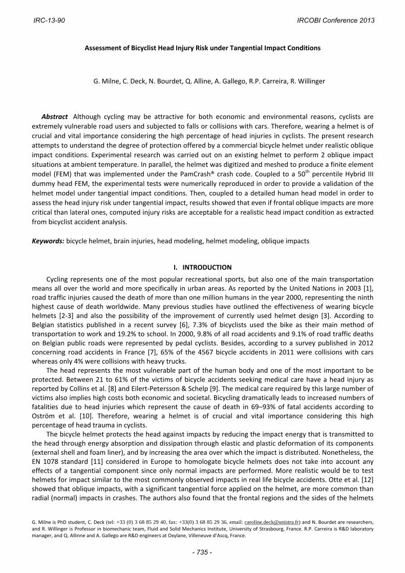
To assess the dynamic energy absorption characteristics of such a helmet in case of tangential impact, automatic electro‐pneumatic shock absorption test equipment with a falling speed up to 8 m/s was used. The helmet was positioned on an instrumented biofidelic 4.5 kg 50th percentile Hybrid III dummy head (Fig. 2) and the retention strap was tightly clamped to maintain the head‐helmet system combined during the test. Three ENDEVCO 7264B/2000 piezoresistive accelerometers capturing accelerations up to 2000 g were placed at the centre of gravity of the headform to measure linear accelerations. One IES 3103‐4800 3‐axes gyro‐sensors measuring angular velocities up to 4800 °/s was also mounted inside the headform. The sensors were linked to an ISO 6487 [28] certified data recorder equipped with a 250 kHz Sensor Input Module (SIM) card. The control software installed on the computer provided tools for performing data collection and display. An oblique anvil was manufactured in XC38 steel with an angle of 60°. As shown in Fig. 3, this anvil was covered by an 80 grain abrasive paper specified in BS 6658 [29] and ECE R‐22.05 [30] standards to represent realistic road‐helmet friction.
Fig. 2. Hybrid III dummy head Fig. 3. Illustration of the 60° anvil covered by abrasive
paper
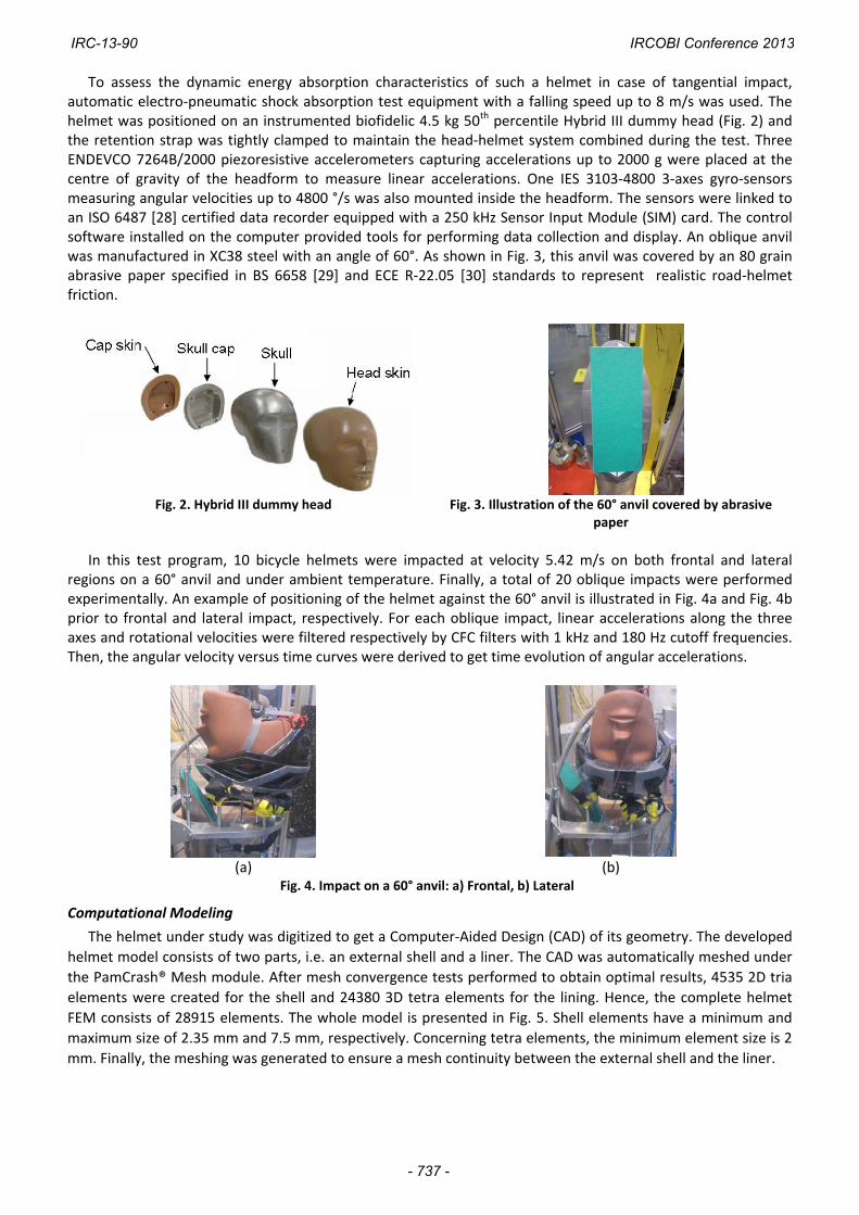
In this test program, 10 bicycle helmets were impacted at velocity 5.42 m/s on both frontal and lateral
regions on a 60° anvil and under ambient temperature. Finally, a total of 20 oblique impacts were performed experimentally. An example of positioning of the helmet against the 60° anvil is illustrated in Fig. 4a and Fig. 4b prior to frontal and lateral impact, respectively. For each oblique impact, linear accelerations along the three axes and rotational velocities were filtered respectively by CFC filters with 1 kHz and 180 Hz cutoff frequencies. Then, the angular velocity versus time curves were derived to get time evolution of angular accelerations.
(a) (b)
Fig. 4. Impact on a 60° anvil: a) Frontal, b) Lateral
Computational Modeling
The helmet under study was digitized to get a Computer‐Aided Design (CAD) of its geometry. The developed
helmet model consists of two parts, i.e. an external shell and a liner. The CAD was automatically meshed under
the PamCrash® Mesh module. After mesh convergence tests performed to obtain optimal results, 4535 2D tria
elements were created for the shell and 24380 3D tetra elements for the lining. Hence, the complete helmet
FEM consists of 28915 elements. The whole model is presented in Fig. 5. Shell elements have a minimum and
maximum size of 2.35 mm and 7.5 mm, respectively. Concerning tetra elements, the minimum element size is 2
mm. Finally, the meshing was generated to ensure a mesh continuity between the external shell and the liner.
IRC-13-90 IRCOBI Conference 2013
- 737 -

Fig. 5. General view of the bicycle helmet finite‐element model
The mesh was imported under the PamCrash® explicit crash code and the material properties of the two
constitutive parts of the bicycle helmet model were implemented. It was observed that under impact, the EPS
foam liner is compressed up to large deformations. In order to simulate such deformations, the EPS behavior
was modeled by a tabulated "General Nonlinear Rate Dependant Foam with Optional Energy Absorption" law
material. The material properties implemented in the model are based on experimental EPS compression tests
at quasistatic strain rate and summarized in Table 1. This quasistatic loading curve is supposed to represent the
material behavior at strain rate “0 /s” according to the PamCrash® formalism for the considered law. Stress
versus strain curves at higher strain rates were extrapolated from the first loading curve by applying scaling
factors deduced from an experiment‐based logarithmic interpolation. The behavior of the EPS is defined by a set
of 8 stress versus strain loading curves, each one related to a strain rate value. Depending on the velocity, a
linear extrapolation beyond the last curve and/or a linear interpolation in between two curves is operated by
the unloading slope Eunloading.
Table 1. Mechanical properties of the EPS foam liner implemented under PamCrash®
ρ (kg/m3) 77
Eunloading (MPa) 10
Tabulated loading curves at ambient temperature
A linear elastic behavior was assumed for the polycarbonate shell and modeled through the “Elastic‐plastic
thin shell material” law. The values of the four parameters had to characterize the PC material, in accordance
with Mills & Gilchrist [25], and are reported in Table 2. A measured thickness value of 1.18 mm was attributed
to all shell elements.
Table 2. Mechanical properties of the PC
shell
ρ (kg/m3) 1200
E (MPa) 2400
ν (‐) 0.35
σyield (MPa) 50
IRC-13-90 IRCOBI Conference 2013
- 738 -

To simulate the 2 oblique experimental tests, a 50th percentile Hybrid III dummy head FEM (Fig. 6a) was imported under the PamCrash® environment. This 4.5 kg headform was meshed with 1888 brick elements and 944 shell elements as shown in Fig. 6b. An accelerometer was defined at the centre of gravity of the head in order to compute rotational accelerations. Moreover, its inertia was in good agreement with that of the physical model as demonstrated in Table 3.
Table 3. Inertia of the 50th percentile Hybrid III dummy head
Model IXX (x10‐3 kg.m²) IYY (x10
‐3 kg.m²) IZZ (x10‐3 kg.m²)
FEM 17.7 18.6 23.4 Physical 17.1 18.9 22.7
The head‐helmet contact of the coupled system illustrated in Fig. 7 was defined by taking into account a
“Symmetric node to segment with edge treatment” interface with a 0.5 friction coefficient.
(a) (b) Fig. 6. Hybrid III dummy head: a) FE model, b) Main components
The geometry and the dimensions of the anvil complied with the EN 1078 prescriptions (minimum diameter
of (125 ± 3) mm and 24 mm thick). The “Null material for shell elements” material law was implemented with parameter values mentioned in Table 4. A “Symmetric node to segment with edge treatment” interface with a friction coefficient of 0.5 was defined to compute the shocks on this inclined anvil.
Table 4. Mechanical properties of the anvil
ρ (kg/m3) 2700
E (MPa) 200000
ν (‐) 0.35
(a) (b)
Fig. 7. Simulation of oblique impact tests at velocity 5.42 m/s on a 60° anvil: (a) Frontal, (b) Lateral
In order to assess the risk of head trauma in terms of DAI and SDH under tangential impacts, a coupling between the bicycle helmet FEM and the Strasbourg University Finite Element Head Model (SUFEHM) was performed under the PamCrash® software. This model developed by Kang et al. [33] and illustrated in Fig. 8 was meshed with 10395 brick elements and 2813 shell elements. Based on anatomical atlas, the head model contains the face, scalp, skull and a homogenous brain. Intracranial membranes and cerebrospinal fluid (CSF) are also represented in this model. The constitutive material laws of the different parts of the model have been defined by the material laws specified in appendix 1 according to Willinger et al. [34]. This model was validated under dynamic experimental tests reported by Nahum et al. [35], Trosseille et al. [36] and Yoganandan et al.
IRC-13-90 IRCOBI Conference 2013
- 739 -

[37]. This 4.7 kg head model has been extensively used for the simulation of a number of well documented real world types of head trauma in order to correlate intra‐cranial mechanical parameters with the occurrence of injury. This approach helped to define model‐based head injury criteria reported by Deck et al. [38], summarized as follows:
50% risk of moderate neurological injury (DAI1+): Brain Von Mises shearing stress of 29 kPa,
50% risk of severe neurological injury (DAI2+): Brain Von Mises shearing stress of 53 kPa,
50% risk of subdural hematoma: minimum pressure of ‐315 kPa in CSF.
The interface between the energy‐absorbing foam and the human head model (Fig. 9a) was computed by a “Symmetric node to segment with edge treatment” PamCrash® contact with a friction coefficient set to 0.5. An example of positioning of the head‐helmet system for a frontal impact against the anvil is shown in Fig. 9b.
Fig. 8. Illustration of the Strasbourg University Finite Element Head Model
(a) (b)
Fig. 9. Helmet‐human head models coupling: (a) Illustration of the head‐helmet interface, (b) Initial positioning of the coupled head‐helmet system against the inclined anvil
III. RESULTS
During the validation process and for each impact location, numerical resultant linear acceleration and
angular acceleration were computed at the centre of gravity of the Hybrid III headform in order to superimpose
them with the respective experimental results. In the framework of this helmet validation effort under oblique
impact configurations, results in terms of time‐history acceleration curves were superimposed with mean
experimental records and their associated standard deviation. Curves were numerically filtered by CFC filters
with 1 kHz and 180 Hz cut‐off frequencies, respectively. An illustration is given for a frontal impact at 5.42 m/s
on a 60° anvil in Fig. 10 and Fig. 11 for resultant linear acceleration and angular acceleration around Y (and X)
axis, respectively. A reasonable agreement is observed in terms of time durations and peak values
demonstrating that the defined stress‐strain curves correspond approximately to the energy‐absorbing material
in the considered loading case. Numerical peak g and peak krad/s² values are 67 g and 5.1 krad/s². Related
experimental values are 60 g and 4.8 krad/s² leading to relative errors less than 10%.
IRC-13-90 IRCOBI Conference 2013
- 740 -

Fig. 10. Superimposition of time‐history resultant linear acceleration curves for a frontal impact (fC = 1 kHz)
Fig. 11. Superimposition of time‐history angular acceleration curves for a frontal impact (fC = 180 Hz)
Time‐history resultant linear and angular accelerations obtained for a lateral impact are shown in Fig. 12 and
Fig. 13. By analyzing the time durations and peak values between numerical and experimental records, a good
agreement is also observed. Numerical simulation of tangential impacts tests led to peak values of 70 g and 4.7
krad/s². Compared to experimental values, relative errors are 5.7% and 18%, respectively.
Fig. 12. Superimposition of time‐history resultant linear acceleration curves for a lateral impact (fC = 1 kHz)
Fig. 13. Superimposition of time‐history angular acceleration curves for a lateral impact (fC = 180 Hz)
When coupled to the human head model, intracranial parameters were computed in order to assess the
injury risks in terms of diffuse axonal injuries and subdural hematoma under tangential impacts, in accordance
with the model‐based injury criteria described in the Methods section. 10 oblique impact configurations
performed with a helmeted head model are illustrated in Table 5. 3 head impact angles and 3 impact velocities
were investigated to assess the influence of both normal and tangential components on head injury risks for a
reasonable range of tangential impact conditions.
Table 5. Oblique impact loading cases simulated with helmeted SUFEHM
Impact α (°) V (m/s) VN (m/s) VT. (m/s)
Frontal
35 6.5 5.3 3.7
45 6.5 4.6 4.6
60
5.42 2.7 4.7
6.5 3.3 5.6
8.0 4.0 6.9
Lateral
35 6.5 5.3 3.7
45 6.5 4.6 4.6
60
5.42 2.7 4.7
6.5 3.3 5.6
8.0 4.0 6.9
IRC-13-90 IRCOBI Conference 2013
- 741 -
As for the numerical simulations with the Hybrid III head FE model, the quality of each simulation was
verified by comparing hourglass to total energy of the system and making sure that hourglass energy did not
exceed 10% of the total energy involved.
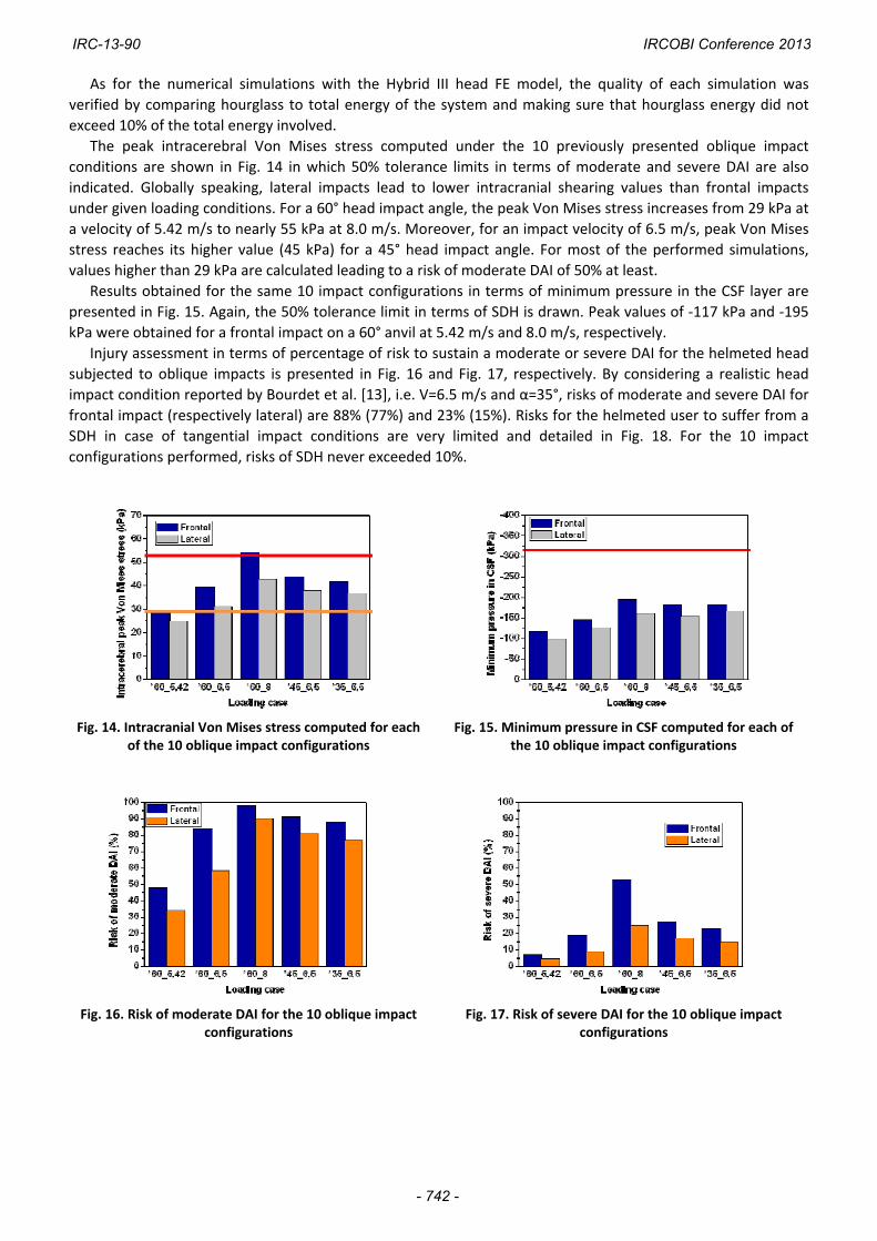
The peak intracerebral Von Mises stress computed under the 10 previously presented oblique impact
conditions are shown in Fig. 14 in which 50% tolerance limits in terms of moderate and severe DAI are also
indicated. Globally speaking, lateral impacts lead to lower intracranial shearing values than frontal impacts
under given loading conditions. For a 60° head impact angle, the peak Von Mises stress increases from 29 kPa at
a velocity of 5.42 m/s to nearly 55 kPa at 8.0 m/s. Moreover, for an impact velocity of 6.5 m/s, peak Von Mises
stress reaches its higher value (45 kPa) for a 45° head impact angle. For most of the performed simulations,
values higher than 29 kPa are calculated leading to a risk of moderate DAI of 50% at least.
Results obtained for the same 10 impact configurations in terms of minimum pressure in the CSF layer are
presented in Fig. 15. Again, the 50% tolerance limit in terms of SDH is drawn. Peak values of ‐117 kPa and ‐195
kPa were obtained for a frontal impact on a 60° anvil at 5.42 m/s and 8.0 m/s, respectively.
Injury assessment in terms of percentage of risk to sustain a moderate or severe DAI for the helmeted head
subjected to oblique impacts is presented in Fig. 16 and Fig. 17, respectively. By considering a realistic head
impact condition reported by Bourdet et al. [13], i.e. V=6.5 m/s and α=35°, risks of moderate and severe DAI for
frontal impact (respectively lateral) are 88% (77%) and 23% (15%). Risks for the helmeted user to suffer from a
SDH in case of tangential impact conditions are very limited and detailed in Fig. 18. For the 10 impact
configurations performed, risks of SDH never exceeded 10%.
Fig. 14. Intracranial Von Mises stress computed for each of the 10 oblique impact configurations
Fig. 15. Minimum pressure in CSF computed for each of the 10 oblique impact configurations
Fig. 16. Risk of moderate DAI for the 10 oblique impact configurations
Fig. 17. Risk of severe DAI for the 10 oblique impact configurations
IRC-13-90 IRCOBI Conference 2013
- 742 -

Fig. 18. Risk of SDH for the 10 oblique impact configurations
IV. DISCUSSION
This paper proposes an evaluation of a FE model of an existing commercial bicycle helmet under tangential impacts. After being subjected to experimental oblique tests, numerical simulations were performed under the PamCrash® crash code to validate the helmet model impacted at 5.42 m/s on 60° anvil and on both frontal and lateral regions. For the impact conditions considered in this study the rotational acceleration is mainly along one single axis only. However, in a further study it would be important to investigate more complex impact situations leading to combined rotational accelerations.
For the two simulations performed, a good agreement with acceptable relative errors has been shown between experimental and numerical results both in terms of time‐history resultant linear acceleration and angular acceleration curves, computed at the centre of gravity of the Hybrid III dummy head FE model. For each impact location, numerical results are within the experimental corridors based on 10 impacts for friction coefficients of 0.5. This is also a limitation of the study and, in a further step, there is a need to conduct a parametric study on these parameters.
In addition, the bicycle helmet model was validated against experimental angular acceleration filtered at 180 Hz. A more pertinent validation could have been proposed if no filtering had been applied on these experimental records. It should be mentioned that this helmet model has been validated under linear impact conditions in an earlier study [27].
Even if current bicycle helmets are designed to reduce headform acceleration, they are still not optimized to reduce human head injuries under tangential impact. In order to progress towards this final objective, head injury risk assessment under tangential impact conditions was performed in the present study. It appears, for the two validated impact configurations, that the risk of severe DAI is less than 7%. A 2% risk of SDH has also been determined. It should be mentioned that the risk of skull fracture was not considered in the present study.
According to the realistic impact conditions reported by Bourdet et al. [13], head injury risks have been assessed for a helmeted head impacting the ground at a velocity of 6.5 m/s and 35°. Risks of severe DAI are 23% and 15%, respectively, for impacts performed at the front and the side, values that are acceptable regarding levels generally accepted in standards.
V. CONCLUSIONS
In this study, a previously published bicycle helmet FE model was implemented and validated under tangential impact condition under the PamCrash® explicit crash code.
The numerical simulation of two experimental oblique impact tests at ambient temperature was performed by coupling the helmet FEM to the Hybrid III dummy head FE model. Results in terms of resultant linear acceleration and angular acceleration versus time curves between experiment and simulation are in good agreement for both impact points.
Once validated, this helmet FE model was coupled to the Strasbourg University FE Head Model in order to
assess the head injury risks of both DAI and SDH injuries. Results show that frontal oblique impacts are more
critical than lateral ones. Results also show that the computed injury risk is acceptable for a realistic head
impact condition as extracted from bicyclist accident analysis. This work is therefore a step towards helmet
optimisation against biomechanical head injury criteria and the consideration of model‐based head injury
IRC-13-90 IRCOBI Conference 2013
- 743 -

criteria in future helmet standards.
VI. ACKNOWLEDGEMENT
The experimental approach has been carried out within the ANR PREDIT Projet “BICYTETE” led by the French
Department of Transport.
VII. REFERENCES
[1] United Nations, Internet: www.un.org/Pubs/chronicle/2003/issue2/0203p78.html [2] Thompson RS, Rivara FP, Thompson DC, A case control‐study of the effectiveness of bicycle safety helmets,
N Engl J Med, 320:1361‐136, 1989. [3] Thomas S, Acton C, Nixon J, Battistutta D, Pitt WR, Clark R, Effectiveness of the bicycle helmets in preventing
the head injury in children: case control study, Brit Med J, 308:173‐176, 1994.
[4] McIntosh AS, Kallieris D, Mattern R, Svensson NL, Dowdell B, An evaluation of pedal cycle helmets performance requirements, 39th Stapp Car Crash Conference, San Diego (California), 1995.
[5] Ching RP, Thompson DC, Thompson RS, Thomas DJ, Chillcott WC, Rivara FP, Damage to bicycle helmets involved with crashes, Accid Anal Prev, 29:555‐562, 1997.
[6] NIS (Statistics Belgium), Mobiliteit 1998–1999, Brussels, 2000.
[7] Observatoire National Interministériel de la Sécurité Routière, Données détaillées de l’accidentalité ‐ Bilan de l’année 2011, juillet 2012.
[8] Collins BA, Langley JD, Marshall SW, Injuries to pedal cyclists resulting in death and hospitalization, N Z Med J, 106(969):514‐516, 1993.
[9] Eilert‐Petersson E, Schelp L, An epidemiological study of bicycle‐related injuries, Accid Anal Prev, 29(3):363‐372, 1997.
[10] Oström M, Björnstig U, Näslund K, Eriksson A, Pedal cycling fatalities in Northern Sweden, Int J Epidemiol, 22:483‐488, 1993.
[11] NF EN 1078 standard, Helmets for pedal cyclists and for users of skateboards and roller skates, S 72‐403, 1997.
[12] Otte D, Chinn B, Doyle D, Mäkitupa S, Sturrock K, Schuller E, Contribution to Final Report of COST 327 Project, University of Hannover, 1999.
[13] Bourdet N, Deck C, Carreira RP, Willinger R, Head impact conditions in case of cyclist falls, Proceedings of the Institution of Mechanical Engineers, Part P: J Sport Eng and Tech 1754337112442326, 2012.
[14] Gennarelli TA, Head injury in man and experimental animals: clinical aspects, Acta Neurochirurgica, 32:1‐13, 1983.
[15] Margulies SS, Thibault LE, A proposed tolerance criterion for diffuse axonal injuries in man, J of Biomechanics, 25(8):917‐923, 1997.
[16] Deck C, Baumgartner D, Willinger R, Influence of rotational acceleration on intracranial mechanical parameters under accidental circumstances, Proceedings of the IRCOBI Conference, Maastricht, The Netherlands, pages 185‐197, 2007.
[17] Aare M, Kleiven S, Halldin P, Injury tolerance for oblique impact test for motorcycle helmets, Int J Crash, 6(1):53‐64, 2001.
[18] Harrison TI, Mills NJ, Turner MS, Jockeys’ head injuries and skull cap performance, Proceedings of the IRCOBI Conference, Dublin, Ireland, 49‐62, 1996.
[19] Halldin P, Gilchrist A, Mills NJ, A new oblique impact test for motorcycle helmets, Int J Crash, 6(1):53‐64, 2001.
IRC-13-90 IRCOBI Conference 2013
- 744 -

[20] Pang TY, Thai KT, McIntosh AS, Grzebieta R, Schilter E, Dal Nevo R, Rechnitzer G, Head and neck responses in oblique motorcycle helmets impacts: a novel laboratory test methods, Int J Crash, 16(3):297‐307, 2011.
[21] Aldman B, Lundell A, Thorngren L, Helmet attenuation of the head response in oblique impacts to the ground, Proceedings of the IRCOBI Conference, Lyon, France, pages 118‐128, 1978.
[22] Mills NJ, Gilchrist A, Response of helmets in direct and oblique impacts, Int J Crash, 2(1):7‐24, 1996.
[23] Mills NJ, Gilchrist A, Oblique impact testing of bicycle helmets, Int J Impact Engng, 35:1075‐1086, 2008.
[24] Willinger R, Diaw BM, Baumgartner D, Development and validation of a bicycle helmet finite element model, Proceedings of the IRCOBI Conference, Göteborg, Sweden, pages 549‐552, 1998.
[25] Gilchrist A, Mills NJ, Finite‐element analysis of bicycle helmet oblique impacts, Int J Impact Engng, 35:1087‐1101, 2008.
[26] Asiminei AG, Van der Perre G, Verpoest I, Goffin J, A transient finite element study reveals the importance of the bicycle helmet material properties on head protection during an impact, Proceedings of the IRCOBI Conference, York, United Kingdom, pages 357‐360, 2009.
[27] Milne G, Deck C, Bourdet N, Carreira RP, Allinne Q, Willinger R, Development and validation of a bicycle helmet: Assessment of head injury risk under standard impact conditions, Proceedings of the IRCOBI Conference, Dublin, Ireland, pages 813‐827, 2012.
[28] ISO 6487 standard, Road vehicles ‐ Measurement techniques in impact tests ‐ Instrumentation, 2002.
[29] BS 6685 standard, Specifications for protective helmets for vehicle users, 1985.
[30] ECE R‐22.05 standard, Uniform provisions concerning the approval of protective helmets for drivers and passengers of motorcycles and mopeds, 1999.
[31] Tinard V, Deck C, Willinger R, Modelling and validation of motorcyclist helmet with composite shell, Int J. Crash, DOI:10.1080/13588265.2011.648465, 2012.
[32] Deck C, Willinger R, Multi‐directional optimisation against biomechanical criteria of a head‐helmet coupling, Int J Crash, 11(6):561‐572, 2006.
[33] Kang HS, Willinger R, Diaw BM, Chinn B, Validation of a 3D human head model and replication of head impact in motorcycle accident by finite element modeling. Proceedings 41th Stapp Car Crash Conf, Society of Automotive Engineers, Lake Buena Vista, USA, pages 329‐338, 1997.
[34] Willinger R, Diaw BM, Kang HS, Finite element modeling of the human head ‐ Modal and temporal validation, Int Conf on Vib Eng, Dalian, China, 1998.
[35] Nahum AM, Smith R, Ward CC, Intracranial pressure dynamics during head impact, 21st Stapp Car Crash Conf, New Orleans, USA, pages 337‐366, 1977.
[36] Trosseille X, Tarriére C, Lavaste F, Guillon F, Domont A, Development of a FEM of the human head according to a specific test protocol, Stapp Car Crash Conf, Seattle, USA, pages 235‐253, 1992.
[37] Yoganandan N, Pintar FA, Sances A, Walsh PR, Ewing CL, Thomas DT, Snyder RG, Biomechanics of skull fracture, Journal of Neurotrauma, 12(4):659‐668, 1995.
[38] Deck C, Willinger R, Improved head injury criteria based on head FE model, Int J Crash, 13(6):667‐678, 2008.
IRC-13-90 IRCOBI Conference 2013
- 745 -

VIII. APPENDIX
APPENDIX 1. MECHANICAL PROPERTIES OF THE SUFEHM CONSTITUTIVE PARTS
Segment Illustration Mechanical behavior
Mechanical parameters
Mechanical parameters
Falx and Tent
Linear elastic
e = 1 mm
ρ = 1140 kg/m3
E = 31.5 MPa
υ = 0.45
/
Brain‐Skull interface
Linear elastic
ρ = 1040 kg/m3
E = 0.012 MPa
υ = 0.49
/
Brain and Cerebellum
Viscous elastic
ρ = 1040 kg/m3
K = 1125 MPa
G0 = 0.049 MPa
Ginf = 0.0167
β = 145 s‐1
/
Skull
Fragile elastic‐plastic
Cortical
e = 2 mm
ρ = 1900 kg/m3
E = 15000 MPa
υ = 0.21
K = 6200 MPa
UTS = 90 MPa
UTC = 145 MPa
Spongy
e = 3 mm
ρ = 1500 kg/m3
E = 4600 MPa
υ = 0.05
K = 2300 MPa
UTS = 35 MPa
UTC = 28 MPa
Face
Linear elastic
e = 10 mm
ρ = 2500 kg/m3
E = 5000 MPa
υ = 0.23
/
Skin
Linear elastic
ρ = 1000 kg/m3
E = 16.7 MPa
υ = 0.42
/
IRC-13-90 IRCOBI Conference 2013
- 746 -