assessment of fishway development and design
TRANSCRIPT

New Concepts in Fish Ladder Design, Volume III of IV
Assessment of Fishway Development and Design
Final Report1982 - 1984
DOE/BP-36523-4 August 1985

This Document should be cited as follows:
Powers, Patrick, Thomas Bumstead, John Orsborn, "New Concepts in Fish Ladder Design,Volume III of IV; Assessment of Fishway Development and Design", 1982-1984 Final Report,Project No. 198201400, 181 electronic pages, (BPA Report DOE/BP-36523-4)
Bonneville Power AdministrationP.O. Box 3621Portland, OR 97208
This report was funded by the Bonneville Power Administration (BPA),U.S. Department of Energy, as part of BPA's program to protect, mitigate,and enhance fish and wildlife affected by the development and operationof hydroelectric facilities on the Columbia River and its tributaries. Theviews in this report are the author's and do not necessarily represent theviews of BPA.
FISHWAYS-AN ASSESSMENT OF THEIRDEVELOPMENT AND DESIGN
Final Project ReportPart 3 of 4
Prepared by
Patrick D. PowersJohn F. Orsborn
Thomas W. BumsteadSharon Klinger-Kingsley
Walter C. Mih
Washington State UniversityDepartment of Civil and Environmental Engineering
Prepared for
Thomas Vogel, Project ManagerU.S. Department of Energy
Bonneville Power AdministrationDivision of Fish and Wildlife
P.O. Box 3621Portland, OR 97208-3621
Project No. 82-14Contract Number DE-AI79-82BP36523
August, 1985
TABLE OF CONTENTS
Page
L I S T O F T A B L E S . . . . . . . . . . . . . . . . . . . . . . . . . . . vi
LIST OF FIGURES . . . . . . . . . . . . . . . . . . . . . . . . . . viii
SUMMARY OF RESEARCH PROJECT REPORTS . . . . . . . . . . . . . . . . xi
ACKNOWLEDGMENTS . . . . . . . . . . . . . . . . . . . . . . . . . . xiii
SHORT GLOSSARY OF FISHWAY TERMS . . . . . . . . . . . . . . . . . . xv
A B S T R A C T . . . . . . . . . . . . . . . . . . . . . . . . . . . . . . xvii
L E G A C Y . . . . . . . . . . . . . . . . . . . . . . . . . . . . . . . xix
INTRODUCTION . . . . . . . . . . . . . . . . . . . . . . . . . . . . 1
HISTORICAL DEVELOPMENT OF FISHWAYS AND THE EVOLUTION OFDESIGN CONCEPT . . . . . . . . . . . . . . . . . . . . . . . . . . 3
Major Developments . . . . . . . . . . . . . . . . . . . . . . . . 11Research on Design . . . . . . . . . . . . . . . . . . . . . . . . 11Pacific Northwest Developments . . . . . . . . . . . . . . . . . . 14
FISHWAY CLASSIFICATION . . . . . . . . . . . . . . . . . . . . . . . 23
1. FISH LADDERS . . . . . . . . . . . . . . . . . . . . . . . . . 23
Entrance Conditions . . . . . . . . . . . . . . . . . . . .Entrance Location . . . . . . . . . . . . . . . . . . . . .Entrance Hydraulics . . . . . . . . . . . . . . . . . . . .Examination of the Pool and Weir/Orifice Types . . . . . . .Vertical Slot Type Fishwayy . . . . . . . . . . . . . . . . .Chute type Fishways . . . . . . . . . . . . . . . . . . . .Exit Conditions . . . . . . . . . . . . . . . . . . . . . .
23242425323437
2. C U L V E R T S . . . . . . . . . . . . . . . . . . . . . . . . . . . 38
Baffled Culverts . . . . . . . . . . . . . . . . . . . . . . 43
3. FISH LOCKS AND FISH ELEVATORS . . . . . . . . . . . . . . . . 45
iii

TABLE OF CONTENTS (Continued)
Page
HYDRAULIC CONDITIONS IN FISHWAYS . . . . . . . . . . . . . . . . . . 46
Pool and Weir Flow . . . . . . . . . . . . . . . . . . . . . . . . 46Chute Floww . . . . . . . . . . . . . . . . . . . . . . . . . . . . 46Orifice and Slot Flow . . . . . . . . . . . . . . . . . . . . . . 48Velocity Calculations . . . . . . . . . . . . . . . . . . . . . . . 48
CAPABILITIES OF FISH AND CONTROLLING CONDITIONS . . . . . . . . . . 51
Introduction . . . . . . . . . . . . . . . . . . . . . . . . . . . 51Swimming Speeds . . . . . . . . . . . . . . . . . . . . . . . . . 52Leaping Ability and Maximum Speed . . . . . . . . . . . . . . . . 57Factors Affecting Fish Speeds . . . . . . . . . . . . . . . . . .Homing . . . . . . . . . . . . . . . . . . . . . . . . . . . . . . ::Energetics . . . . . . . . . . . . . . . . . . . . . . . . . . . . 60
LOCOMOTION AND HYDRODYNAMICS . . . . . . . . . . . . . . . . . . . . 63
Introduction . . . . . . . . . . . . . . . . . . . . . . . . . . . 63Swimming Modes . . . . . . . . . . . . . . . . . . . . . . . . . . 65Basic Equations of Fluid Flow . . . . . . . . . . . . . . . . . . 66Relationships Between Flow Conditions and Fish Speeds . . . . . . 68
A CONCEPTUAL, ANALYTICAL MODEL OF THE ENERGY REQUIREMENTS OFASCENDING FISH . . . . . . . . . . . . . . . . . . . . . . . . . . 73
Basic Fluid Mechanics and Fish Capabilities . . . . . . . . . . . 73Swimming Through a Port . . . . . . . . . . . . . . . . . . . . . 75Swimming Up a Sloping Channel . . . . . . . . . . . . . . . . . . 77Leaping Over a Waterfall or Weir . . . . . . . . . . . . . . . . . 88Summary of Energy Requirements for Fish to Ascend Through Ports,
Up Chutes or Over Weirs . . . . . . . . . . . . . . . . . . . . 91
THE ROLES OF STIMULUS, RESPONSE, AND STRESS IN THE DESIGN OF FISHPASSAGE STRUCTURES . . . . . . . . . . . . . . . . . . . . . . . . 93
Introduction . . . . . . . . . . . . . . . . . . . . . . . . . . . 93Stimulus and Response . . . . . . . . . . . . . . . . . . . . . . 94Stresses . . . . . . . . . . . . . . . . . . . . . . . . . . . . . 97
SALMONID PREFERENCE FOR HIGHER VELOCITIES DURING UPSTREAM MIGRATION . 100
Introduction . . . . . . . . . . . . . . . . . . . . . . . . . . . 100TestDataa . . . . . . . . . . . . . . . . . . . . . . . . . . . . . 100Methods of Analysis . . . . . . . . . . . . . . . . . . . . . . . . 101
iv

TABLE OF CONTENTS (Continued)
Page
Analysis to Include Chance . . . . . . . . . . . . . . . . . . . . 101Summary . . . . . . . . . . . . . . . . . . . . . . . . . . . . . . 105
DESIGN SURVEY AND INTERVIEWS . . . . . . . . . . . . . . . . . . . . 106
Attraction Velocity . . . . . . . . . . . . . . . . . . . . . . . . 107Observations of Fish Passage . . . . . . . . . . . . . . . . . . . 108Design Philosophies . . . . . . . . . . . . . . . . . . . . . . . . 109
SOME CONSTRUCTION CONSIDERATIONS . . . . . . . . . . . . . . . . . . 120
APPENDIX I .--BIBLIOGRAPHY . . . . . . . . . . . . . . . . . . . . . 125
APPENDIX II.--- RESEARCH SUMMARY FOR THE INITIAL DEVELOPMENT OF NEWCONCEPTS IN WEIR AND POOL FISH LADDER DESIGN . . . . . . . . . . . 142
V

LIST OF TABLES
Table
1. Fishway characteristics . . . . . . . . . . . . . . . . . . . .
2. Fish-subsystem characteristics . . . . . . . . . . . . . . . .
3. Pool and Weir, and Pool and Orifice Types . . . . . . . . . . .
4. Summary of design criteria for pool and weir/orifice fishladders for use with Figure 21 . . . . . . . . . . . . . . .
5. Vertical slot fishway dimensions and criteria . . . . . . . . .
6. Summary of Steeppass floor and side fin angles . . . . . . . .
7. Water velocity relationship to resting pool distance for salmon,steelhead, and resident trout . . . . . . . . . . . . . . . .
8. Popular and scientific names of some common anadromous andresident commercial and sport fish species . . . . . . . . .
9. Nominal upper limits of sustained, prolonged, and burst speedsof adult fish . . . . . . . . . . . . . . . . . . . . . . . .
10. Some historical highlights of the study of fish locomotion from600 B.C.-1971 . . . . . . . . . . . . . . . . . . . . . . . .
11. Summary of equations used in the analysis of fish and flowrelationships . . . . . . . . . . . . . . . . . . . . . . . .
12. Frontal area as a function of fish length when resting andswimming . . . . . . . . . . . . . . . . . . . . . . . . . .
13. Selected values of burst speeds . . . . . . . . . . . . . . . .
14. Water velocity in a chute for roughness, n = 0.01 . . . . . . .
15. Energy requirement for swimming up a chute for roughness,n=0.03 . . . . . . . . . . . . . . . . . . . . . . . . . .
16. Distance against velocity for adult sockeye swimming up aninclined plane using Eq. (21) . . . . . . . . . . . . . . . .
17. Energy requirement for leaping from a level pool for afour-pound fish . . . . . . . . . . . . . . . . . . . . . . .
Page
5
5
25
27
32
37
41
51
55
64
69
74
75
80
82
85
89
vi

LIST OF TABLES (Continued)
Table
18. Energy requirement for leaping from a standing wave for afour-pound fish . . . . . . . . . . . . . . . . . . . . . . .
19. Summary of energy requirements of a four-pound ascending fishswimming through a port, up a chute, and leaping anequivalent height . . . . . . . . . . . . . . . . . . . . . .
20. Environmental passage conditions for a fishway unit . . . . . .
21. Velocity combinations and data reduction for analyzing theselection of the higher velocity channel by silver andchinook salmon and steelhead trout . . . . . . . . . . . . .
22. Data reduction and velocity combinations for analyzing theselection of the higher velocity channel by silver andchinook salmon and steelhead trout using the momentumdifference between two attraction flows and theirmomentum--a fish attraction factor . . . . . . . . . . . . .
23. List of addresses for Fishway Design Questionnaire . . . . . .
24. Fish Ladder Questionnaire for International Survey . . . . . .
25. Discussion topics for personal interviews during the period ofJune, 1982-September, 1984 . . . . . . . . . . . . . . . . .
26. Summary of responses to Questions 5, 6, and 3 of theInternational Survey . . . . . . . . . . . . . . . . . . . .
27. Composite of fishway design questions resulting from interviewsand survey responses . . . . . . . . . . . . . . . . . . . .
Page
90
92
95
101
102
110
112
113
114
117
vii
LIST OF FIGURES
Figure
1. Nomenclature and characteristics of a fishway flow system . . .
2. Nomenclature and characteristics of a fish subsystem . . . . .
3. Nomenclature and characteristics of fishway subsystems . . . .
4. Ice Harbor type pool, weir and port fishway at Lower Granitedam on the Snake River near Wawawai, Washington . . . . . . . .
5. Full overflow weir fishway at Easton diversion dam in theheadwaters of the Yakima River, Washington . . . . . . . . . .
6. Single-slot fishway on Mill Creek diversion dam in SoutheasternWashington . . . . . . . . . . . . . . . . . . . . . . . . . .
7. Denil-type fishway at culvert outlet on Hastings Creek nearVancouver, British Columbia . . . . . . . . . . . . . . . . . .
8. Alternating-weir fishway at Johns Creek hatchery near Shelton,Washington at high flow . . . . . . . . . . . . . . . . . . . .
9. Two versions of WSU pool-weir-baffle fishway installed at JohnsCreek hatchery with the same total drop as in Fig. 8 underexcessively high flow for observation . . . . . . . . . . . . .
10. MacDonald's steep slope Fishladder of 1879 in Virginia . . . .
11. Plan view and section of Landmark's first slotted Fishway . . .
12. Denil's early fishpass with roughness elements on floora n d w a l l s . . . . . . . . . . . . . . . . . . . . . . . . . .
13. Denil's fishway modifications with emphasis on wall roughnessand smooth floor . . . . . . . . . . . . . . . . . . . . . .
14. Initial Bonneville overflow weir and submerged orifice ladder .
15. Hell's Gate double-slotted fishway on the Fraser River inBritish Columbia . . . . . . . . . . . . . . . . . . . . . .
16. Ice harbor fishladder design with double weir and double port .
17. Type A, Alaska Steeppass/Denil No. 6 Fishway . . . . . . . . .
Page
2
6
6
8
8
9
9
10
10
12
12
13
13
16
17
18
20
viii

LIST OF FIGURES (Continued)
Figure
18. Aeroceanics spiral fishway . . . . . . . . . . . . . . . . . .
19. Pipe f
20. Warnernear
21. Nornenc
shway for trout at Helena Lake, British Columbia . . . .
Fishlift installed at Cariboo Dam on the Brunette RiverBurnaby, British Columbia . . . . . . . . . . . . . . .
ature sketch for weir and port fishladder . . . . . . .
22. Section through Corps of Engineers beveled weir crest and port
23. Profile shape of weir floor suggested by Menzies . . . . . . .
24. Cross section of weir with circular base and flared top similarto WSU weir design . . . . . . . . . . . . . . . . . . . . .
25. Orifice-tube fishladder sloping down 45 as developed byICE Committee on Fish Passes- . . . . . . . . . . . . . . . .
26. Sloping, centerline-orifice fishway developedand Nemenyi . . . . . . . . . . . . . . . .
27. Inclined pipe orifice fishway . . . . . . . .
28. Nomenclature sketch for slotted fishways show is l o t t y p e . . . . . . . . . . . . . . . . .
29. Institution of Civil Engineers modified Denil
by McLeod. . . . . . . . .
. . . . . . . . .
ng single. . . . . . . . .
Fishway . . . . .
30. Typical dimensions of Alaska Steeppass Fishway . . . . . . . .
31. Two vertical slot baffle systems developed at the BonnevilleFisheries-Engineering Laboratory for controlling fishway flowwhen forebay elevation fluctuates . . . . . . . . . . . . . .
32. Relationship of relative swimming speed to relative length forartic grayling . . . . . . . . . . . . . . . . . . . . . . .
33. Culvert Baffle arrangement suggested by McKinley and Webb . . .
34. Hydraulic conditions for shooting and plunging flow after Bell
35. Rating curves for Alaska Steeppass Type A fishway . . . , . . .
ix
Page
20
19
22
26
28
29
29
30
31
31
33
35
36
39
42
44
47
50

LIST OF FIGURES (Continued)
Figure Page
36. Interrelationships of fish and velocity during four life stageswith emphasis on upstream migration . . . . . . . . . . . . . 53
37. Speed, fatigue time and fish size for young rainbow and sockeye 56
38. Body shape during propulsive cycle for subcarangiform motion ofSalmo gairdneri taken at 0.03 sec. intervals . . . . . . . . 65
39. Nomenclature for velocity profile . . . . . . . . . . . . . . . 70
40. Velocity distribution downstream of a port . . . . . . . . . . 76
41. Open channel flow . . . . . . . . . . . . . . . . . . . . . . . 78
42. Sockeye swimming velocity related to fatigue time . . . . . . . 87
43. Distance that adult sockeye can swim before tiring as a functionof channel roughness and slope . . . . . . . . . . . . . . . 86
44. Angle of velocity of leaping from a quiet pool . . . . . . . . 88
45. Choice of higher velocities by upstream migrating salmon andsteelhead related to momentum level in the attraction flowsas defined by the momentum difference divided by theaverage momentum in the two jets . . . . . . . . . . . . . . 104
46. View of Rogers Creek fishway and falls . . . . . . . . . . . . 122
47. Turning chamber near entrance to Rogers Creek fishway ath i g h f l o w . . . . . . . . . . . . . . . . . . . . . . . . . . 122
48. Rogers Creek weir:baffle:pool fishway operating at a flow of afew cubic feet per second . . . . . . . . . . . . . . . . . . 123
49. Rogers Creek weir:baffle:pool fishway operating at anintermediate flow of about six to seven cubic feet per second 123

SUMMARY OF RESEARCH PROJECT REPORTS
Bonneville Power AdministrationBPA Fisheries Project 82-14
DEVELOPMENT OF NEW CONCEPTS IN FISH LADDER DESIGN
Conducted at theAlbrook Hydraulics Laboratory
Department of Civil and Environmental EngineeringWashington State University
Pullman, Washinqton 99164-3001
Project Period: June, 1982-October, 1984
1. Orsborn, John F. 1985. SUMMARY REPORT
A synopsis of the project components was prepared to provide anoverview for persons who are not fisheries scientists or engineers.This short report can be used also by technical persons who areinterested in the scope of the project, and as a summary of thethree main reports. The contents includes an historicalperspective on fishway desiqn which provides the basis for thisproject. The major project accomplishments and significantadditions to the body of knowledge about the analysis and design offishways are discussed. In the next section the research projectorganization, objectives and components are presented t ofamiliarize the reader with the scope of this project.
The summary report concludes with recommendations for assisting inthe enhancement and restoration of fisheries resources from theperspective of fish passage problems and their solution. Promisinqresearch topics are included.
2. Aaserude, Robert G. and John F. Orsborn. 1985. NEW CONCEPTS INFISHLADDER DESIGN. --Results of Laboratory and Field Research on NewConcepts in Weir and Pool Fishways. (With contributions by DianeHilliard and Valerie Monsey).
The drivinq force behind this project, and the nucleus from whichother project components evolved, was the desire to utilize fishleaping capabilities more efficiently in fishway desiqn. Thisreport focuses on the elements which were central to testing thepremise that siqnificant improvements could be made in water use,costs and fish passage efficiencies by developing a new weir andpool fishway. These elements include: historical review ofavailable information; optimization of weir geometry; fluid jetmechanics; air entrainment; enerqy dissipation in the pool chamber;and fish capabilities. The new weir and pool chambers were testedin the field with coho and chum salmon.
xi
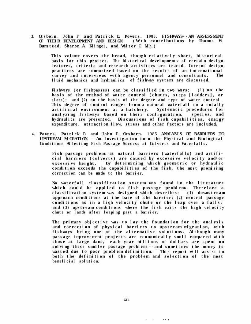
3. Orsborn. John F. and Patrick D. Powers. 1985. FISHWAYS--AN ASSESSMENTOF THEIR DEVELOPMENT AND DESIGN. (With contributions by Thomas W.Bumstead, Sharon A. Klinger, and Walter C. Mih.)
This volume covers the broad, though relatively short, historicalbasis for this project. The historical developments of certain designfeatures, criteria and research activities are traced. Current designpractices are summarized based on the results of an internationalsurvey and interviews with agency personnel and consultants. Thefluid mechanics and hydraulics of fishway systems are discussed.
Fishways (or fishpasses) can be classified in two ways: (1) on thebasis of the method of water control (chutes, steps [ladders], orslots); and (2) on the basis of the degree and type of water control.This degree of control ranges from a natural waterfall to a totallyartificial environment at a hatchery. Systematic procedures foranalyzing fishways based on their configuration, species, andhydraulics are presented. Discussions of fish capabilities, energyexpenditure, attraction flow, stress and other factors are included.
4. Powers, Patrick D. and John F. Orsborn. 1985. ANALYSIS OF BARRIERS TOUPSTREAM MIGRATION. --An Investigation into the Physical and BiologicalConditions Affecting Fish Passage Success at Culverts and Waterfalls.
Fish passage problems at natural barriers (waterfalls) and artifi-cial barriers (culverts) are caused by excessive velocity and/orexcessive height. By determining which geometric or hydrauliccondition exceeds the capabilities of the fish, the most promisingcorrection can be made to the barrier.
No waterfall classification system was found in the literaturewhich could be applied to fish passage problems. Therefore aclassification system was designed which describes: (1) downstreamapproach conditions at the base of the barrier; (2) central passageconditions as in a hiqh velocity chute or the leap over a falls;and (3) upstream conditions where the fish exits the high velocitychute or lands after leaping past a barrier.
The primary objective was to lay the foundation for the analysisand correction of physical barriers to upstream migration, withfishways being one of the alternative solutions. Although manypassage improvement projects are economically small compared withthose at large dams, each year millions of dollars are spent onsolving these smaller passage problems --and sometimes the money iswasted due to poor problem definition. This report will assist inboth the definition of the problem and selection of the mostbeneficial solution.
xii

ACKNOWLEDGMENTS(BPA Fisheries Project 82-14)
The financial support for this project was provided by the BonnevillePower Administration, Portland, Oregon. The project was initiated prior tothe time that the Fish and Wildlife Program of the Northwest Power PlanningCouncil was developed and initiated. The results of this project have alreadyfound, and will continue to find, many opportunities for application to theproblems addressed in the NPPC Fish and Wildlife Program for the ColumbiaRiver Basin.
We wish to express our gratitude to numerous active and retired agencypersonnel and consultants who responded to our design questionnaire andparticipated in personal interviews. The names and addresses of many arelisted in other parts of this report, but those who were especially helpfulinclude:
F. J. Andrew - International Pacific Salmon Fisheries CommissionDoug Arndt - NPD, USCEBill M. Bakke, Director, Trout and Salmon Resource CenterKen Bates - WDOFMilo Bell - ConsultantTed Bjornn - Idaho Cooperative Fishery UnitRoger Bogden - WDOGBert Carnegie - ODFWWayne Daley - KCMBrian Dane - Canadian Fisheries and Marine ServiceMike Dell - Grant Co. PUDIvan Donaldson - RetiredEdward Donahue - Fish Pro ConsultantsRay Finnigan - Canadian Fisheries and Marine ServiceM. Fretwell - International Pacific Salmon Fisheries CommissionJim Haas - ODFWThomas M. Humes - Consulting Western, Ltd., Cranbrook, B.C.John Hutchins - Anderson, Bjornstad, Kane and JacobsChris Kellogg - Corrosion Controllers, Inc.Christine Moffitt - Idaho Cooperative Fishery UnitBob Pearce - NMFSJim Riis - South Dakota Dept. of Game, Fish and ParksCharles Ritzi - Consultant, Winthrop, MaineEmil Slatick - NMFSHugh Smith - RetiredGerry Taylor - B.C. Ministry of the EnvironmentClark Thompson - RetiredChuck Wagner - RetiredDick Weaver - RetiredRuss Webb - WDOF
xiii
Our special acknowledgement of helpful cooperation goes to the WashingtonDepartment of Fisheries for the use of its hatcheries for field testing of ournew fishway designs In particular we wish to thank Dennis Popochock for useof the Johns Creek facility.
The advice, guidance, criticism and support of our BPA contractingofficer's representative, Thomas S. Vogel, were extremely important to thesuccess of this project.beneficial.
His suggestions at critical points were very
The project personnel were:
Robert G. AaserudeRobin BayleyThomas W. BumsteadKathy CoxDiane HilliardPeter HinesC. J. KhistySharon A. Klinqer
Ann E. MartinsonWalter C. Mih
(Co-Principal Investigator)Valerie MonseyB. J. NaikJohn F. Orsborn
(Principal Investigator)Patrick D. Powers
xiv

SHORT GLOSSARY OF FISHWAY TERMS
ALASKA STEEPPASS: a type of Denil fishway developed for use in remote areasof Alaska; prefabricated of metal in sections which can be connectedon site; has vanes on floor and sides to reduce velocity; high aircontent in flow.
ATTRACTION FLOW: flow exiting the downstream end of the fishway; the fishway
BAFFLE:
BARRIERS:
DENIL:
flow is sometimes augmented by the auxiliary flow to form a largerattraction flow; auxiliary flow is usually needed where there arecompeting flows which could attract fish from the fishway entrance,such as from powerhouses, spillways or waterfalls.
any protrusion on the floor and/or walls of a chute or channel usedto create an energy loss (velocity reduction) in the flow; largebaffles provide a wake behind the baffle where fish can rest; inhydraulic engineering a baffle is any device which is used to dissi-pate (baffle) kinetic energy (caused by velocity).
to upstream migration; physical and chemical; natural and artificial;debris and log jams; chutes, falls, culverts, temperature; chemical.
a fishway chute with roughness elements (baffles, vanes) on thesides and floor which cause the average velocity to be reduced; muchair is entrained which reduces the attractiveness of the flow at thedownstream end of the fishway; usually constructed as a connectingfishway between resting pools, a chute and pool fishway.
FISH LADDER: a type of fishway consisting of a series of steps (like a lad-der) or drops for dissipati ng water energy in expansion eddies inpools.
FISH PASS: term for fishway; more commonly used in Europe.
FISH SPEEDS: (or velocity) defined in three ranges: sustained, prolongedand burst (formerly called cruising, sustained and dart or burst)speeds; fish can swim sustained indefinitely without tiring; prolong-ed speeds are for 20 sec. to 200 min. but fish will become exhausted;and burst speeds can be maintained for 5-20 secs. and result inexhaustion. Burst speeds are used fur leaping. Speeds are a func-tion of fish size, species, condition, life phase and water quality.A steelhead maximum burst speed is about 28.0 ft/sec (fps).
FISHWAY: general term for any flow passage which fish negotiate by swimmingand/or leaping; can be a high velocity chute, a cascade or verticalwaterfall in nature; can be a man-made (artificial) structure such as
xv
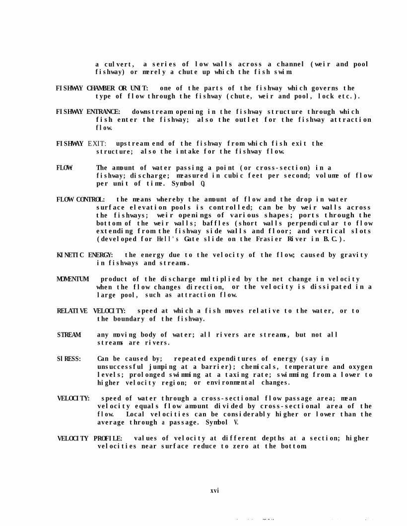
a culvert, a series of low walls across a channel (weir and poolfishway) or merely a chute up which the fish swim.
FISHWAY CHAMBER OR UNIT: one of the parts of the fishway which governs thetype of flow through the fishway (chute, weir and pool, lock etc.).
FISHWAY ENTRANCE: downstream opening in the fishway structure through whichfish enter the fishway; also the outlet for the fishway attractionflow.
FISHWAY EXIT: upstream end of the fishway from which fish exit thestructure; also the intake for the fishway flow.
FLOW: The amount of water passing a point (or cross-section) in afishway; discharge; measured in cubic feet per second; volume of flowper unit of time. Symbol Q.
FLOW CONTROL: the means whereby the amount of flow and the drop in watersurface elevation pools is controlled; can be by weir walls acrossthe fishways; weir openings of various shapes; ports through thebottom of the weir walls; baffles (short walls perpendicular to flowextending from the fishway side walls and floor; and vertical slots(developed for Hell's Gate slide on the Frasier River in B.C.).
KINETIC ENERGY: the energy due to the velocity of the flow; caused by gravityin fishways and streams.
MOMENTUM: product of the discharge multiplied by the net change in velocitywhen the flow changes direction, or the velocity is dissipated in alarge pool, such as attraction flow.
RELATIVE VELOCITY: speed at which a fish moves relative to the water, or tothe boundary of the fishway.
STREAM: any moving body of water; all rivers are streams, but not allstreams are rivers.
SlRESS: Can be caused by; repeated expenditures of energy (say inunsuccessful jumping at a barrier); chemicals, temperature and oxygenlevels; prolonged swimming at a taxing rate; swimming from a lower tohigher velocity region; or environmental changes.
VELOCITY: speed of water through a cross-sectional flow passage area; meanvelocity equals flow amount divided by cross-sectional area of theflow. Local velocities can be considerably higher or lower than theaverage through a passage. Symbol V.
VELOCITY PROFILE: values of velocity at different depths at a section; highervelocities near surface reduce to zero at the bottom.
xvi

Fishways--An Assessment of TheirDevelopment and Design
ABSTRACT
Various areas of scientific and engineering endeavor in natural resourcesdevelopment and maintenance receive oscill ating amounts of attention andsupport. As a result, and as reflected in the literature on fishways, thestate-of-the-art receives pulses of useful information from research and themonitoring of completed projects. For example, such pulses of effort occurredin Britian and the United States in the late 18OOs, in Belgium between 1908and 1939, in Britain and the United States again from 1936 to 1940, and in thePacific Northwest on the Columbia River in the period from 1950s to the 1970s.
Certain classical types of fishways have emerged from the documentationof this effort such as: the Denil chute fishway, the Alaska steeppass, theIce Harbor pool-port-weir fish ladder, and the Hell's Gate slotted fishladder. Variations on each of these basic designs number in the tens, andthey have been developed usually to meet specific site conditions, to handlesmaller or fewer fish, or to test new design variables under prototypeconditions.
The design criteria developed from these experiences have emerged in asomewhat conservative aura. As a result, natural selectivity has been lost atsites where fishways have greatly reduced the size of the energy expenditureincrements required for fish to negotiate a reach of stream. Designedfishways initially dealt with fish response to various flow configurations.But in the last 30-40 years more attention has been paid to stimulus,attractive releasers and response in fish passage design. Numerous empiricalstudies have developed a rich reservoir of hydraulic and geometricinformation, and their associated design criteria.
But, many fishway desiqn topics have not received a fundamental analysisfrom the biomechanical and fluid mechanical perspectives. Also, many of thedesiqn criteria have not been thoroughly tested (not observed, but tested)with fish in prototype situations. As a result there is room for improvementsin efficiency-- in the efficiency of fish passage, water usage and economics.For example, doubling the leaping heiqht for a weir and pool fishway, forcertain species would cut the cost of the structure by almost 50 percent.Water economies would result only at sites where there are competing uses forthe flow, but that does not obviate the basic design objective of minimizingwater use under any circumstances. Although numerous theoretical studies onthe locomotion of fish and their hydrodynamic advantage have been reported,the instances wherein the results of these studies have been applied to theimprovement of fishway designs have been scarce.
xvii

Therefore, we have explored some of the components of fishway theory,design and construction through: literature assessments, personal designsurveys and interviews, theoretical and applied analyses (and testing) ofstimuli, and the energy expenditure of ascending fish in various passagemodes. A fundamental analysis of attraction flows, based on data from theUSCE Bonneville Fisheries-Enqineering Laboratory, supplies the physical basisfor fishway attraction flow design. Tests using typical fishway attractionflow and stream geometries with various species of fish are still needed toexpand this analysis.
Because much of the current fishway construction is being done in moreremote and smaller systems, some consideration has been given to the use ofalternative construction methods and materials. Also, because of the breadthand depth of the project an extensive bibliography is included in this volume.This report concludes with an appendix which summarizes the early stages ofdevelopment of a new weir, pool, and baffle fishway. Although testing hasbeen conducted with only two species of salmon, the early results are verypromising.
xviii


INTRODUCTION
The 1874 statement by Jonn Muir below the picture on the previous pagewas used in the Introduction for Part 1 of this four-part report. It bearsrepeating because as Muir noted over 100 years ago, if dams are built, thensuccessful fish ladders should be an integral part of those dams. The loss ofthe court case in 1825 over the construction of an illegal dam (without afishway) caused the demise of the St. Croix River run of Atlantic salmon inMaine. Our history shows other similar cases across the United States whichare more numerous than can be justified on any basis.
If an artificial barrier to upstream migration is created (a dam,culvert, or box bridge) an alternate passage route must be provided for theanadromous and/or resident fish. The alternate route should not add to thelevel of stress (or even total energy expenditure) compared with the level ofenergy expenditure experienced by the fish under pre-dam conditions. Thecomparative analysis of pre-migrating adult fish is complex,
and post-dam energy expenditure by upstreamand can use many frames of reference. The
analysis can range from site specific to total energy available to the fishfrom the ocean to the spawning site (Idler and Clemson, 1959; Osborne, 1961).
In this volume of our four-part project report we have prepared a seriesof in-depth sections which deal with bio-engineering aspects of fishwayanalysis and design. One of those sections covers the development of aconceptual model of the energy expended by ascending fish in negotiating afishway by swimming and/or leaping.
If one considers energy as a "flow" term (rate of expenditure of energy),a similar systematic approach can be taken to the characterization of the verycomplex bio-enqineerinq systems we call fishways. All the flow (Q) componentsof a fishway system (shown in Fiq. 1) are numbers, volumes or events per unittime, for example the number of fish per hour, QFI (Flow of Fish Into the thefishway from the downstream end of the structure).
One qeneral approach to the systematic analysis of complex structures isto define the (fishway) system with a boundary as shown by the dashed line inFig. 1. The ENVIRONMENT is beyond the control of the system and provides theINPUTS to the system, such as the streamflow (QS). Some of the inputs dividewith a portion going over the barrier (QSB) which is still "streamflow " andother portions going through the fishway (QFW), or around it, to appear in theentrance chamber as auxiliary flow (QAX). At fishways where auxiliary flow(QAX) is added to the fishway flow (OFW),attraction flow (QAT).
they combine to form the OUTPUT

FIGURE 1.
Nomenclature and Characteristics of a Fishway Flow System
QLSl-7
QAX \ &L-
QFW ~-\ -FISHWAY *
UNITST -I- T
INDI ITS -v- OUTPUTS
Q = Flow
QS = Stream
QSB = Barrier
QFW = Fishway
QAX = Auxiliary
QD =Debris
QDF = Debris to Fishway
QDB = Debris to Barrier
QAT = Attraction
QFI = Fish In
QFO = Fish Out
QFF = Fish Fallback
QLS = Landslide
2

Within the fishway its passage flow input (QFW) is "operated on" withinthe fishway system and changed in terms of energy forms (velocity and depth).The flow energy changes depend on the type of fishway, whether it is merely aroughened chute, pool and weir or slotted fishway (see Glossary on pagesxv-xvi).
The fishway system includes the barrier which necessitated theconstruction of the the fishway, be it a dam, waterfall, cascade, rock chuteor culvert. This approach accounts for the fact that the stream and debrisflows divide when the fishway is external to the barrier. In the case of aculvert, or a box bridge with a floor, the fishway could be either internalor external to the barrier.
Not all the inputs, and corresponding outputs are shown in Fig. 1 toreduce congestion. For example, debris flow (QD) is shown as having a partialinput to the fishway (QDF), but it is not shown as an output. Debris can beone of the major problems in fishway operation if not avoided by correctintake placement, deflectors, trashracks and/or timely maintenance. Debris isnot shown as an output in Fig. 1, because it will usually be deposited withinthe fishway and removed. Bedload gravels, if allowed to enter the fishway,can reduce the pool volume, increase flow-through velocities, and thusdecrease the resting space for fish.
Some of the flow terms can have both positive and negative components.For example
QFO (Fish Out) = QFI (Fish In) - QFF (Fish Fallback) (1)
when considered over some time period. As a simple measure of fish passageefficiency one could use
PassageEfficiency
= g$ = QFI-QFFQFI (2)
Conditions in the fishway must be conducive to timely upstream migration forthe fish to stay within the biological time clocks of the species involved.
The most positive (or negative) factor affecting fishway performance isthe attraction flow where
QAT (Attraction) = QFW (Fishway) + QAX (Auxiliary) (3)
Not only must (QAT) compete with spillway, waterfall and/or powerhouse flowsfor fish attractiveness, but positioning the fishway entrance too fardownstream will negate its function. The fish move as far upstream as theycan go, usually to the base of the barrier, where they respond to thestrongest flow momentum (discharge times velocity), flow concentrations anddisturbances in the flow pattern.

Any system can be described generally by five-common CHARACTERISTICS, andcan be subdivided into interdependent subsystems for closer functionalanalysis. The fishway characteristics are listed in Table 1 within the fivegroupings of: objectives, functions, management, resources, and theenvironment. The OBJECTIVES describe what purpose the system seeks toachieve. The FUNCTIONS are those actions (verbs) undertaken to achieve theobjective(s). Notice in Table 1 that fishway functions are characterized bythe action verbs of attract, provide and return. MANAGEMENT exerts controlthrough monitoring, feedback and regulation of operation. This can range fromcomplex control systems for fishways at dams, to the natural flow fluctuationsof a slotted fishway at a waterfall. One must consider both natural andartificial management factors influencing fishway operation, theirinteractions and their exclusiveness.
The RESOURCES of a fishway system are all the means available toachieve the objectives. As discussed earlier the ENVIRONMENT includes allthe factors outside the control of the fishway system which affect itsperformance. Fishways constructed along an unstable hillside can be adverselyaffected by landslides (QLS). Though rare and intermittent, they can totallynegate the objective functioning of the fishway. The size of the disturbanceand the rate of change in conditions would usually be beyond the capacity of afishway to continue to function without major maintenance or reconstruction.
If we consider an in-depth analysis of a fishway (referring to Fig. l),we must of course reduce it to a series of subsystems including:
o The upstream chamber (fishway exit, water intake)0 The fishway units (or passage chambers)o The downstream chamber (fishway entrance chamber, water outlet)
But, it is imperative that we consider the biomechanical subsystem of thefish whose five system characteristics are listed in Table 2. The matching ofthese fish subsystem characteristics with those the fishway is required forsuccessful passage (Tables 1 and 2). The various nomenclature for the fishsubsystem are depicted in Fig. 2. Again, for the subsystem as defined, someof the influencing conditions have not been included directly, such asvelocity, or pressure.approaching the fishway,
Velocity is included within both streamflow (QS)and the attraction flow (QAT). Pressure is a
function of the flow depth at which the fish passes, plus local velocityconditions. The hydraulics and fluid mechanics equations governing the fishsubsystem in a fishway and the stream environment are presented in subsequentsections of this report on the:
o Hydraulics in Fishways0 Capabilities of Fisho Locomotion and Hydrodynamics, a n do Energy Expenditure of Ascendinq F i s h .
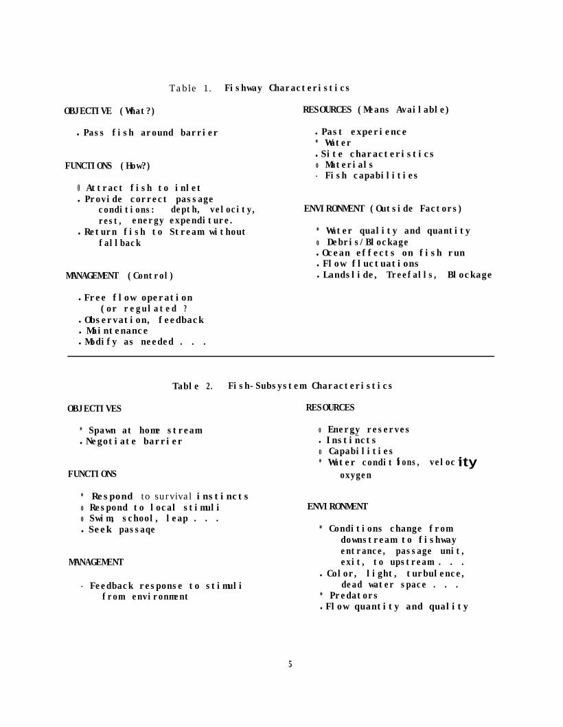
Table 1. Fishway Characteristics
OBJECTIVE (What?) RESOURCES (Means Available)
l Pass fish around barrier l Past experience* Waterl Site characteristics
FUNCTIONS (How?) o Materials- Fish capabilities
0 Attract fish to inletl Provide correct passage
conditions: depth, velocity, ENVIRONMENT (Outside Factors)rest, energy expenditure.
l Return fish to Stream without * Water quality and quantityfallback o Debris/Blockage
l Ocean effects on fish runl Flow fluctuations
MANAGEMENT (Control) l Landslide, Treefalls, Blockage
l Free flow operation(or regulated ?
l Observation, feedbackl Maintenancel Modify as needed . . .
OBJECTIVES
Table 2. Fish-Subsystem Characteristics
RESOURCES
o Energy reserves* Spawn at home streaml Negotiate barrier
.._l Instinctso Capabilities* Water condit
oxygenions, veloc ity
FUNCTIONS
* Respond to survival instinctso Respond to local stimulio Swim, school, leap . . .l Seek passaqe
MANAGEMENT
- Feedback response to stimulifrom environment
ENVIRONMENT
* Conditions change fromdownstream to fishwayentrance, passage unit,exit, to upstream . . .
l Color, light, turbulence,dead water space . . .
* Predatorsl Flow quantity and quality
5

FIGURE 2.
Nomenclature and Characteristics of a Fish Subsystem
QQ = Flow quallty, temperature,
P= Predators
ENVIRONMENT
FIGURE 3.
Nomenclature and Characteristics of Fishway Subsystems
PASSAGE CHAMBER
ENVIRONMENT
6
The nomenclature sketches of the three basic parts (subsystems) of thefishway (exit, passage and entrance chambers) are presented in Fig. 3 in moredetail than in Fig. 1. The fish subsystem must be interjected into each oneof fishway subsystems in sequence to analyze the transient environmentalconditions which help, or hinder, fish passage through the structure. In thecase of chute fishways, such as a Denil, Alaska steeppass or culvert (seeGlossary) the fishway system becomes only the passage chamber. The fishwayentrance and exit are the tailwater and headwater pools, respectively.
The analysis, design and operation of a fishway can range from simple toextremely complex, depending on the degree of naturalness or artificialityexisting at the site. One needs only to review Figs. l-3 and Tables 1 and 2to reinforce this range of complexity and simplicity. These figures andtables are only the representations (models) of fishways as conceptualized bya few "modelers." Other persons might visualize (model) fishways fromdifferent perspectives. But, hopefully the general systems approach aspresented will meet the needs of numerous disciplines associated withfishways. As stated by Stuart (1962) "the perfect fish pass has not yet beendesigned," (nor modeled).
The first major section of this volume traces the historical developmentof fishway design. In preparation for this discussion a series ofphotographs, covering examples of various types of fishways, has beenprepared in Figs. 4-9 on succeeding pages.
The weir and port fishway in Fig. 4 is used at Snake and Columbia Riverdams, and has developed from the original full-width weir and pool type offishway shown at Easton Dam on the Yakima River (Fig. 5). Although slottedfishways are usually considered to be fish ladders, with drops between pools,slotted fishways (as shown in Fig. 6) can be visualized as chutes with largewall baffles. Chute fishways with smaller baffles on the walls and floor toreduce velocity are of the Denil type shown in Fig. 7.
During the testing of our new fishway at John's Creek hatchery nearShelton, we temporarily replaced the alternating weir fishway (Fig. 8) withseveral versions of the new weir-pool-baffle fishway (Fig. 9). The historicaldevelopment of fishways discussed in the next section covers the evolution ofdesign concepts and their associated criteria.
7


HISTORICAL DEVELOPMENT OF FISHWAYS AND THEEVOLUTION OF DESIGN CONCEPTS
Major Developments
Five major events in fishway development have occurred since the earlynineteen hundreds. These include: (1) 1908-1939 research by G. Denil fromBrussels, Belqium: (2) 1936-1938 research by The Institution of CivilEnqineers, Committee on Fish Passes in England: (3) 1939-1940, studiesconducted by McLeod and Nemenyi at Iowa University; (4) 1943-1946, thedevelopment of the vertical slot fishway for use at Hell's Gate, Fraser river,BC: and (5) 1951-1972 the U. S. Army Corps of Engineers and the Bureau ofCommercial Fisheries research programs at the Bonneville Fisheries EngineerinqResearch laboratory.
Before the early nineteen hundreds there was a period of fishwaydevelopment in which detailed plans were made, but no scientific approach wastaken. The objective was to retard the velocity in a steep channel to allowfish passaqe. One attempt appeared in 1879, when Marshall MacDonald fromVirqinia invented a fish pass which consisted of a timber trouqh two feet wideby two feet deep, with a slope of 1:3 as shown in Fig. 10. The flow enteredthe sides of the fishway and was deflected back upstream by buckets to reducethe velocity of the main flow. Even though MacDonald's fishway was anoutstandinq idea at that time, his analysis was so incomplete that his fishwaywas abandoned.
At the time MacDonald built his steep slope ladder, Landmark wasdesigning pool and weir ladders to pass fish over natural falls in Norway.These ladders consisted of a chain of pools which were formed by blastinqthrouqh rock formations. Landmark revised this desiqn by installing weirsobliquely to one wall and extendinq across but not joininq the opposite wall(see Fiq. 11). Simple jet deflectors were placed on the opposite wall,creating a narrow slot which extends the full heiqht of the weir (McLeod andNemenyi, 1941).
Research on Design
The first attempt to approach fishway desiqn scientifically andsystematically was initiated by Denil in 1908. Denil's objectives were todescribe the nature and maqnitude of the resistances encountered by miqratinafish and their ability to overcome such resistances. From this work hedeveloped the first successful fishway at that time, as shown in Fiq. 12. Thisfishway consisted of a series of symnetrical "teeth-like" baffles which trans-ported momentum from the central part of the channel to the walls. The maindrawback of this fishway was its inadaptability to variations in water level.To provide for a qreater variation of water level, Denil devised a narrow deep
11

M A N
F L O W
Figure 10. MacDonald's steep slope Fishladder of 1879 in Virginia.
F L O W - - - - - - ,
CROSS SECTION
Figure 11. Plan view and section of Landmark's first slotted Fishway(Norway, circa 1890).
12

47%B
‘, ’p&c.’ ,t* <,’. \* \\ \
PLAN PROFILE
G=t- 56%8
22968
CROSS SECTION
Figure 12. Denil's early fishpass with roughness elements on floorand walls.
CROSS SECTION
Figure 13. Denil’s fishway modifications with emphasis on wall roughnessand smooth floor.
13

channel fishway with only side baffles as shown in Fiq. 13. He suggestedthat the bottom of the channel should be flat because bottom baffles werehydraulically effective for only a limited ranqe of water depth.
Another drawback of Denil's first fishway was that the baffleconfiquration did not lend itself to construction in concrete, and metal ortimber had to be used. Denil's channels showed a marked scientific advance,but more important than the results was the stimulus it gave to the fields ofichthyology, fish protection and the application of hydraulic engineerinq tofisheries problems.
Following upon Denil's work,(1942), Committee on Fish Passes,
The British Institution of Civil Engineerslaunched an investigation to study fish
passes just prior to World War II. The appendix of the Comnittee's reportincludes hydraulic research done on fish passes by White and Nemenyi inEngland (1942). Their comprehensive research covered: (1) jet dispersion inchambers; (2) experiments in pool overfalls; (3) resistance to be overcome byswimminq fish; (4) relations between depth, slope, and flow in open channels;(5) flow in systematically-roughened steep channels; (6) deflection of a sub-merqed jet to obtain lateral spreadinq; and (7) the upward deflection of asubmersed jet.
Twenty-five different fishpasses were tested in this study, and based onenerqy dissipation the dimensions and qeneral arrangements were determined.The Committee's intention to conduct tests with prototypes was stopped due tothe onslauqht of World War II.
McLeod and Nemenyi continued this work at Iowa University (1939-41) andtested the fishways with fish. At this time there were no model studies withfish on record. The water for their prototype testina was taken from the IowaRiver and the fish used were actually migrating up the river. The types ofladders tested were:
(1) Pool and overfall(a) straight overfall(b) notched overfall (one side and alternate)
(2) Pool and submerged orifice(a) abrupt jet deflection
(3) Paired-obstacle baffled fishways(4) Alternate-obstacle baffled fishways(5) Modified Denil fishways
Results of these studies led to recommendations for new designs andconcepts concerninq energy dissipation.
Pacific Northwest Developents
With the construction of the Bonneville Dam on the Columbia River in1937-38 the development of fish facilities was forced to reach a climax,because the preservation of the anadrotnous fish was deemed essential to the
14

economy of the Pacific Northwest reqion. The U. S. Fish and Wildlife Serviceand the Fisheries agencies of Washinqton and Oreqon were responsible for thehydraulic and bioloqical details of the fish passage facilities. The initialBonneville ladders were 35 feet wide, with standard overflow-weirs andsubmerged orifices on a line adjacent to each wall (see Fiq. 14). This ladderis similar to the ones tested by McLeod and Nemenyi (1939). They suqqestedthat submerged jets on a centerline should be avoided, and that they should hestaqqered. Rut in the McLeod and Nemenyi study, the orifice openings were 40to 50 percent of the baffle width, whereas the Bonneville ladder orificeopeninqs are only about 10 percent of the baffle width.
In 1914, due to construction of a railroad, a large rock slide occurred inHell's Gate canyon on the Fraser River in British Columbia. The accumulationof rock and debris partially blocked the upstream passage of the larqe runs(2,400,OOO) of sockeye salmon. This situation was approached by theInternational Pacific Salmon Fisheries Commission (Clay, 1961). The siterequired a new application of fishway principles, because conventionalstep-type ladders could not handle the daily six-foot fluctuations in waterlevel.
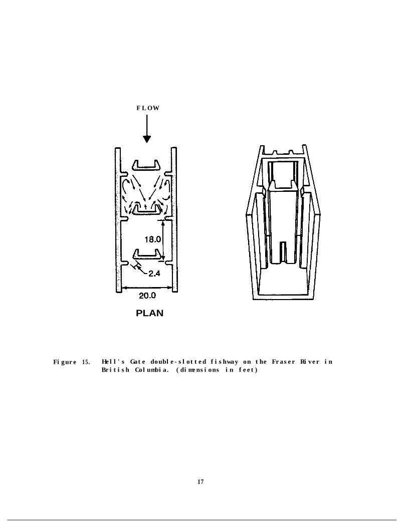
The fishwav developed for this situation, the vertical slot baffle (seeFiq. 15) was desiqned so that the flow from the two slots met in the center ofthe fishway to dissipate the energy. Otherwise the length of the pool wouldhave to he used for enerqy dissipation, thus increasing the costsiqnificantly. This was the first recorded instance where fishway dimensionswere determined from the volume of fish required to accommodate peak runs. Avolume of two cubic feet of water was used as the minimum requirement for eachfish. For the application of this new fishway to smaller runs, the desiqn washalved along the centerline. Because of the loss in symmetry the jet energydissipation takes place in the corner of the pool. To adjust for the tendencyof the jet to turn directly downstream towards the next slot, the baffledimensions were adjusted and a sill was added (up to 12 inches in heiqht)across the slot on the fishway floor. This fish ladder has proved verysuccessful in fish passage and is still preferred today by most fishwaydesiqners of large and small facilities.
After Hell's Gate, proposals to build more dams on the Columbia riverwere the main stimulus for fishway research. The absence of definite criteriaor standards for use in large fishway system desiqns prompted the Corps ofEnqineers to initiate a program of fisheries research in 1951. This proqramhas provided bioloqical information on fish and their capabilities, and in1962 developed the Ice-Harbor fishladder for the newly constructed Ice HarborDam on the Snake River (see Fiq. 16). The main difference between this typeand the standard overflow weir with submerqed orifices is the addition of avertically extended center portion of the weir wall. This extended portion,with short winq walls projectinq upstream, danpens oscillations which producetransverse waves across the full width overflow weir, as was shown in Fiq. 14.
Since the development of the Colunbia River dams fishway design emphasishas been limited to small projects. One earlier innovation which occurred inthe early 1960s was developed by Gil Ziemer of the Alaska Department of Fish
15

I 35.0 I
I-m
-!
2.06.0
c l w =xH ,c1.37s
T0.208
CROSS SECTION
-I
0.4 17+
0.67 -I
2.0
I
r-O.146
h- 0.208
///+/ 2.0
/
,’ 4.0
9 *
PROFILE
Figure 14. Initial Bonneville overflow weir and submerged orifice ladder.(dimensions in feet)
16
F L O W
PLAN
Figure 15. Hell's Gate double-slotted fishway on the Fraser River inBritish Columbia. (dimensions in feet)
17

16.0
F L O W
PLAN
3.0 1.5
CROSS SECTION
-63
-417
.5
Figure 16. Ice Harbor fishladder design with double weir and double port.(dimensions in feet)
18

and Game. This fishway is constructed of aluminum and is lightweight,corrosion resistant and an excellent energy dissipator. It was desiqned tospecifically meet the needs of passaqe problems in remote areas with accessonly by air. The side baffles are similar to models tested by McLeod andNemenyi usinq the modified Denil Type No. 6, as shown in Fiq. 17.
Another type of fishway developed in 1976 is the Aeroceanics spiralfishway (see Fiq. 18). It is constructed of fiberqlass reinforced plasticwith alternating vertical baffles projectinq 0.75 feet into the channel. Likethe Alaska steeppass fishway, the Aeroceanics fishway consists of sections
These twowhich are liqht enouqh to be helicoptered into remote areas.fishways are examples of the onqoinq search for a low-cost, fishway. Another circular fishway is under development which usesflow control. Further information is not available at this time.major construction benefits of circular fishways is that they arefoundation efficient.
liqht-weislotsOne ofs p a c e
ghtfortheand
A DOE study by Truebe and Drooker (1981) contains very comprehensive dataon a number of smaller fishway applications and construction options. Aunique pipe fishway was installed throuqh the dam at Helena Lake in BritishColumbia (Smallwood, 1982). The end of the pipe fishway in the reservoir ismounted on a float which adjusts the gradient on the fish pipe as thereservoir fluctuates as shown in Fiq. 19.
Figure 19. Pipe fishway for trout at Helena Lake, British Columbia.( U s e d with permission of Ducks Unlimited, Sept./Oct., 1982, p. 15)
19

FWS
27
‘nut’PROFILE
Row
-Raw
-525 IN
-FWS
Figure 17. Type A, Alaska Steeppass/Denil No. 6 Fishway.
eorrouTROUGH
0.75
Figure 18. Aeroceanics spiral fishway. (dimensions in feet)
20

Based on preliminary test results, one of the most effective fishelevators appears to be the Warner "Fishlift." Its qeometry and operationalp r o c e d u r e s are displayed in Fig. 2 0 . The photograph on the le f t shows t h e1982-85 test arranqement at Cariboo Dam on the Brunette River near Burnahy,British Columbia, just south of Vancouver.
The "Fishlift" system operates by raisinq and lowerinq a column of water,with the fish being raised or lowered in the upper few feet of water, andsupported by a wire-mesh floor. The fish underqo no pressure chanqe, and twounits can be intertied to operate alternately off the same water supplysystem, thus reducing possible delays due to interrupted operation. Thefacility was modified to handle downstream migrating smolts in 1985 with "100%passage success.n1
Fishway design has evolved over a period of 75 years. Biological datathat was not available 75 years aqo are now documented. Except for accurateleapinq abilities of salmon and trout, swimminq speeds and the ability tosustain these speeds have been determined (Bell, 1984). Fishway design at thepresent is leaning towards smaller, low-cost facilities that do not requirethe excessive amounts of water that many of the present fishways do. Part ofthis impetus for water conservation in fishway desiqn has come from the recentdevelopment of many small-scale hydroelectric projects and proposals for othersmall-scale sites. An economic incentive is present in all designconsiderations, but the most important design feature in any fishway systemshould be the expeditious transport of fish past the barrier that is blockinqor delayinq their upstream migration.
l Warner, J., 1985. Personal communication.
21


FISHWAY CLASSIFICATION
This report will classify fishways three ways: 1) fish ladders includingchutes, 2) culverts, and 3) fish locks and elevators. Each of these is asystem used to pass fish through or over a natural or manmade barrier. At
large hydroelectric dams, the fishway consists of three major components: theentrance, passage, and exit sections. Because chutes usually connect pools,they can be a form of fish ladder, but with larger steps. Culverts which areinstalled at stream road crossings can pose problems to upstream fishmigration through: (1) poor entrance conditions, (2) high velocities andshallow depths in the culvert barrel, and (3) steep exit conditions due toculvert differential and/or rock accumulation at the entrance. Culverts formone of the major groups of barriers to upstream migration and are one of themost critical types of fishways to design. Therefore, they are thoroughlyaddressed in Part 4 of this project report (Orsborn and Powers, 1985). Locksand elevators are used at a few dams to mechanically transport the fish overthe obstruction, but are mechanical and intermittent in operation.
1. FISH LADDERS
Entrance Conditions
As noted in many publications on fishway design, the fishway entrance isthe single most important part of any fishway system. This is especially trueat hydroelectric projects where large flows from the draft tube and spillwaycan obliterate the relatively small attraction flow from the fishway.
In the early 195Os, part of the Corps Fisheries Research Program investi-gated which water velocity was most suitable for entrance attraction. Two
criteria utilized were the swimming ability of the fish and the response offish to a choice of velocities. Fish were allowed to choose between a higherand a lower velocity in each test. In almost every case, a greater percentageof the fish tested entered the channel of higher velocity. Even when the fishwere swept back after failing to pass through the test flume they selected thehigher velocity on their second attempt. Collins (1951) showed that even witha velocity of 13 fps, 80 to 90 percent of the salmon and steelhead preferredthe higher velocity compared to a lower velocity of 3 fps. This study isanalyzed further in a later section of this report on the analysis ofattraction velocity.
Two factors to be considered in the design of fishway entrances are theirlocation and hydraulics. The following is a list of general recommendationsabstracted from the literature on fishway entrances.
23

Entrance Location
At hydroelectric plants, the main fishway entrance should be locatedalonq the shore or between the spillway and powerhouse at the farthestdistance upstream (Clay, 1961). This is true for almost every barrierconfiquration.
The powerhouse collection system should extend over the entire lenqth ofthe powerhouse with openinqs over each unit (Clay, 1961).
The attraction water should form a riqht anqle with the direction inwhich the river flows and be situated just downstream of the point wherethe turmoil of the water falling over the weir finishes (Deelder, 1958).
Entrance Hydraulics
Attraction velocity should be 4 to 8 fps, preferably in the 8 fps ranqe(Bell, 1984).
Cross velocities should not exceed 2 fps (Bell, 1984).
Auxiliary water velocity should be in the 0.25 to 0.75 fps ranqe (Clay,1961), when it issues into the entrance chamber.
Approach flow should be parallel to the axis of the entrance weir, or atleast no greater than 25 percent to the axis of the main current(Mahmood, 1972).
Entrances to powerhouse collection systems should be vertical, adjustableorifices 2 feet wide by 5 feet hiqh located at a depth of 3 feet(Thompson, 1967).
Attraction (stream) should be 7 feet deep by 10 feet wide extendinq 50feet into the bay for large dams (Corps, Charles River, 1977).
Denil-type ladder entrances should be submerqed to a depth of 2.5 feet(Slatick, 1969).
As can be seen from the above summary about fishway entrance conditions,most of the published literature is on larger structures where they are sodifficult to manaqe.
Ladders can be classified into four types: 1) pool and weir, 2) pool andorifice, 3) vertical slot type, and 4) chute type. Chutes are equivalent tosteps in a ladder as fish travel from pool to pool, while using swimminq astheir mode of transport.
24

Examination of the Pool and Weir/Orifice Types
For classifying ladder types, the pool and weir and pool and orifice willbe combined because many combinations exist, such as the Ice Harbor ladder.For the purpose of this report, pool ladders will be classified as shown inTable 3.
Table 3. Pool and Weir, and Pool and Orifice Types
A Notched overflow with submerged orifice
c"Straight overflow with submerqed orificeNotched overflow without submerged orifice
D Non-overflow with submerqed orifice
Weir and orifice type ladders present the fish with two routes ofpassagee --either swimming through the orifice, or by swimminq or jumping overthe weir. Fig. 21 is a diaqram of pertinent dimensions which apply to thesetypes of ladders. The dimension locates the center line of the over flowsection. Table 4 is a matrix of accepted design factors which apply to pooltype ladders. The desiqn of the baffle wall is straight forward, but theshape of the weir crest and the shape and placement of the orifices areimportant features which require more detailed consideration.
Most desiqners warn that sharp crests should be avoided because the fishmiqht be injured, but a well desiqned weir should allow the fish to passwithout contactinq the weir. Tests done by the Corps of Enqineers haveresulted in a beveled weir crest shown in Fiq. 22. This crest was found todampen oscillations which were present with the flat, square weir crests. Mostof the dams on the Columbia River have incorporated the beveled crest. TheInstitution of Civil Enqineers Committee on Fish-Passes in 1936 experimentedwith ten different weir crest profiles, and concluded that no specialattention need be qiven to this, but that a semi-circular cross-section isvery satisfactory.
In Scotland, where there is a noticeable preference for pool and weirtype ladders, Menzies (1934), suggests a weir crest with a downstream curvelike a wave section (see Fig. 23). This crest shape is desiqned to produce asolid unbroken body of black water qlidinq into the pool below with a minimumof disturbance to itself and the pool. The weir-section shape sugqested byMenzies is similar to one recommended by Sedqwick (1982). He noted that weirshapes should be downward curving with a rounded base as shown in Fig. 24.
Submerged orifices were introduced to control the depth of flow over theweir crest, while limitinq the total volume of water flowinq throuqh the pass.The Committee on Fish Passes (1942) suqqested that the dissipation of asubmerqed jet beqins along the surface of the unbroken jet; hence, aconsidernhle lenqth of pool is necessary. They also sugqest that the orificeshould be converqent (i-o., inlet = 1.4 outlet), the inlet bell-mouthed, all
25

WC= WEIR CREST LENGTH
w,X
I
I II I
ow =ORlFlcE Ir’l ~~~cE~~~~~~
II :III
d=POOL
DEPTH
I e=PooL WIDTH
CROSS SECTION
HO-HEADBETWEEN POOLS
I
dw=DEPlH OVER WEIR
I
+ LA- CREST
- L- POOL LENGTH PROFILE
8- ORIFKX BAFFLEWALL ANGLE
PROFILE
Figure 21. Nomenclature sketch for weir and port fishladder.
26


0.42 3.17 0.083
1.0
Figure 22. Section through Corps of Engineers beveled weir crestand port. ( dimensions in feet)
28

Figure 23. Profile shape of weir floor suggested by Kenzies (1934).(dimensions are in feet)
!$;$Jj
.: .. . i :..:..-- ._. :;.‘.‘.“.‘. . ..__-... . _..__ .* _,
,.: . . . . .-. :: - ‘,.. -:. ._. :.:..*:. . . _a:. . . . . . . . . . . ;I
Figure 24. Cross section of weir with circular base and flared topsimilar to WSU weir design (see Project Report Parts 1and 2). (dimensions are in feet)
29

edges rounded to a smooth surface, and the orifice sloped downward at an anqleof 45 degrees to the horizontal (see Fig. 25). McLeod and Nemenyi suggestedan orifice arrangement where the baffle wall is sloped 55 degrees downstreamfrom the ladder bottom, and the orifices are in the middle on a center line asshown in Fig. 26.jet deflection"
This type of arrangement has been given the name "abruptas the jet is deflected onto the floor of the ladder at a
35-degree angle. Decker (1956) suggested a ladder identical to McLeod andNemenyi's. Neither of these publications suggest a shape for the orifice andit is assumed that they used a square opening without rounded upstream edqes.Orifices on the Columbia River ladders are square openings with the upstreamand downstream sides beveled similar to the beveled weir crest shown in Fig.22 at 45 degrees.
Another orifice arrangement is a type of inclined cylindrical or pipe-type orifice (Clay, 1961) which has been used in Scottish fishways (see Fiq.27). The length of the cylinder recommended is about 1.5 to 2.0 times thepipe diameter. The preference for this type was confirmed through a FishLadder Ouestionnaire response from Scotland (Sedgwick, 1982), in which henoted this was a successful underwater orifice type of ladder for passingsalmon.
6.0
Figure 25. Orifice-tube fishladder sloping down at 45" as developedby ICE Committee on Fish Passes (1942). (dimensions arein feet)
30

0.83
PROFILE CROSS SECTION
Figure 26. Sloping, centerline-orifice fishway developed by McLeodand Nemenyi (1939-40). (dimensions are in feet)
6.25
CONCRETE P IPE
Figure 27. Inclined pipe orifice fishway. (dimensions are in feet)
31

In Russia, a design providing a conical qrating guide on the upstreamside of the orifice has been developed by Antonnikov (1964). Two orificeswork in combination with a straiqht overfall-weir wall (Type B) ladder. Thistype of orifice lends itself to debris problems, and when clogged acts as asolid, conical opening. Another type of opening was developed by Michel andNadeau (1965), et the Lava1 University Hydraulic Laboratories. This orificehas a Borda mouth piece (parabolic) opening. It is supposed to duplicate theflow conditions chosen in nature by salmon and trout as they progress upstreamresting behind stones in the stream bed. This orifice is combined with a non-overfall baffle (Type D) ladder, and was installed in the Nabisipi River inFrance. It is reported by Mahmood (1972) to be working satisfactorily.
Vertical Slot Type Fishway
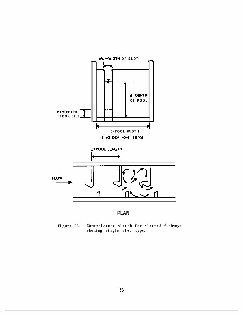
There are two types of vertical slot fish ladders used: 1) pairedvertical slot (the original Hell's Gate design), and 2) single vertical slot(see Fig. 28). the latter being a half model of the first and in morecommon use. Table 5 includes design factors from Clay (1961) and Bell(1984). This fish ladder allows fish to pass at any depth, and adapts well tofluctuations in the water level.
Table 5. Vertical Slot Fishway Dimensions and Criteria
Pool DimensionsaPublisher us HP Pool Space L B d Hf
Clay (1961) 12” (min)b 12" 2 ft3/fish 10’ 8' f(Q)*6" (min)c 9" (pink, (optfZal)**
chum)
Bell (1973) 12” 12” (max) 0.2 ft3 per 10’ f(Q) (optional)( 1984) 24" lb. fish 16.5' 1::
Notes: a) Pool size = f (slot width): see nomenclature in Fig. 28.b) Salmon 5 lbs. or more.c) Salmon or trout 2 lbs. or less.
*f(Q) : Function of fishway flow.**Floor sill has been found to be helpful in preventing fallback.
32
Ws -WIDTH O F S L O T
I+ = HEIGHTF L O O R S I L L
d=MPTHO F P O O L
m-w.
v
4B - P O O L W I D T H
CROSS SECTION
LtPOOL LENGTH
PLAN
Figure 28. Nomenclature sketch for slotted fishwaysshowing single slot type.
33

The most critical dimension in this type of ladder is the slot width.This is a function of the fish size, and once determined, allows determinationof pool size for proper energy dissipation.
When a vertical slot ladder is installed at a natural barrier the routeof ascent presents a path that was not available before the ladder wasinstalled. Therefore, predatory species which are usually weaker swimmers,can now negotiate the falls or rapids and are introduced into the newlyopened spawning grounds.
Chute Type Fishways
The function of a chute type ladder is based on the original work done byDenil in 1908 in which baffles acted as roughness elements to reduce the flowvelocity down the chute. Two distinct types recommended in the designliterature are: 1) the one developed by the Institution of Civil Engineers(ICE), Committee on Fish Passes (1942), and 2) that developed by the AlaskaDepartment of Fish and Game under the guidance of Gil Ziemer (1962).
The ICE Committee on Fish Passes tested 25 baffle types and selected themost practical (see Fig. 29). This type is also recommended by Fisher (1964),and Decker (1956). The accepted design dimensions are included in Fig. 29.The maximum suggested length for a 1:5 slope is 30 feet. Continuous flow isobtained at a velocity of 6 fps and a flow rate of 21 cfs. This produces adepth of 3 feet. Ten cfs would produce a depth of two feet. For this type ofchute, the maximum recommended change in water level is 12 inches. To providefor greater variation of water level, the Committee suggests a deep narrowchannel fishway, as devised by Denil, with only side baffles of herring boneform. This type has been constructed at a natural barrier on the PacificCoast by the Washington State Department of Fisheries on the Coweman River. Astudy done by Clausen and Floodeen (1954) suggests that the deep narrowchannel type works best with the entrance rounded to decrease the contractionof the jet which produces drawdown at the water entrance, and in turnincreases velocities. The rounding produced a full channel width flowimnediately upon entering the chute.
The Alaska Department of Fish and Game in the early 1960s developed theAlaska Steeppass fish ladder (see Fig. 30). The baffle configuration is thesame as that developed by McLeod and Nemenyi (1939), modified Denil No. 6.McLeod and Nemenyi suggest construction of either concrete or wood, but theAlaska steeppass is an aluminum, corrosion resistant, pre-fabricated, light-weight channel in 10 foot units. Each unit weighs 55 pounds per lineal foot.The estimated maximum number of fish that can pass is 750 per hour. Thevelocities range in the 3-5 fps range, with a full discharge of about 9 cfs ,depending on the depth of the unit. Slopes vary from 20-35 degrees. Fourmodels have been developed. Table 6 is a comparison of (0, downstream)horizontal angle of the fins and (Q) upstream vertical angle of the fins.Velocities in the Model (or type) A steep pass range from 2.8 to 3.3 fps for a
34


FLOW
27 I N
22 I N
I FINS
11 IN ’PROFILE
e FLOW
Figure 30. Typical dimensions of Alaska Steeppass (ASP) Fishway.
36

slope of 20-35 degrees, and 4.1 to 4.5 fps for the same slope in model C.Model C was developed to reduce the air entrainment and turbulence present inmodel A. Because of the high velocities obtained in the model C, the verticalangle of the fins was adjusted back to 77.5 degrees, which is the model D.
Table 6. Summary of Steeppass Floor and Side Fin Angles
Alaska Steeppass Floor Fin Angle Side Fin AngleModel Phi, 0, degrees Theta, 0, degrees
ABCD
9 0Variable4577.5
The Department of the Environment, Fisheries Service of Canada hasincreased the depth in the model C steeppass by 2.0 feet in order toaccammodate a greater headwater range. Hydraulic test results have not beenpublished on these deeper units.
Exit Conditions
When fish exit a ladder, whether it be at a natural obstruction or a dam,the main concern is for fish being swept back downstream (a type of externalfallback). Studies at Ice Harbor Dam on the Snake River in 1962 (Corps ofEngineers, 1966) showed that 18.7 percent of the north ladder upstreammigrating fish fell back through the spillway during a period of low riverflow compared to 3.5 percent of the south ladder fish. The north ladder exitis 150 feet from the spillway and the south ladder exit is 1100 feet from thenearest spill gate. At a higher flow situation fallback increased.
The National Marine Fisheries Service in 1979 developed a list ofcriteria which apply to the fish ladder exit section. These are:
1. Avoid exit location next to spillway or powerhouse intakes. Extendexit upstream if necessary to avoid fallback;
2. Avoid locating exit in stagnant area where water quality may be poor;it should be located in area of positive downstream flow;
3. Exit should have a trash boom and/or trash rack:
37

Trash rack--Vertical bars 8 inches clear minimum spacing (Chinook):
--Horizontal bars 18 inches clear minimum spacing;
--Cleaned by rake:
4. Provide structural freeboard to prevent flood damage;
5. Provide stoplogs or a closure gate for ladder maintenance anddewatering;
6. Exit water depth--4 feet minimum,--6 feet preferred;
7. Maximum exit velocity at low forebay should be 2.0 fps.
In large fishway systems such as the ones on the Columbia and Snake RiverDams, the exit section of the ladder is used to regulate the flow entering theladder. This is known as the control section. Devices used consist ofstoplogs, adjustable height weir gates, tilting weirs and combinations ofdifferent sizes of orifices and slots. Orifice control sections wereintroduced in the 1960s in the Columbia River fishways. The facilities wereintended primarily for salmon and steelhead trout, but numerous shad, andscrap fish with less enerqy capabilities and different swimming habits wouldnot use the submerged orifice opening and the ladder pools became overcrowded.
In 1969, studies at the Bonneville Fisheries-Engineering ResearchLaboratory resulted in the design of two vertical slot type baffles (see Fig.31) for control sections. These have been used successfully on the ColumbiaRiver dams (Washington), Connecticut River dams and the Charles River dam inMassachusetts. The baffle walls have varying orifice sizes and slot floorsill heights which regulate the flow and, along with the auxiliary water,provide a constant ladder discharge as forebay elevations vary.
At the Lower Granite dam on the Snake River, the control section consistsof Type C baffles with nine pools, each 16 feet long. The sill height startsat six inches and increases by six inches with every pool upstream. Thisaccepts a forebay elevation change of five feet. At the downstreamtermination of this control section, the addition of water through a diffusionchamber maintains a constant flow of about 72 cfs through the overflow weirand submerged orifice section (Ice Harbor Type).
2. CULVERTS
A culvert is a conduit used for conveying water through an embankment.The embankment may be for a highway, railway, street, dams, or levee. themanner in which this water is conveyed is where the problem arises for fish
38

24.0
Q * \/x
t
'&---
f .Ir/ 1
I IP-YGT-~
TYPE E - PLAN
MTYPE C-PLAN
F L O W
Figure 31. Two vertical slot baffle systems developed atthe Bonneville Fisheries-Engineering Laboratoryfor controlling fishway flow when forebayelevation fluctuates.

passaqe. This section will describe current practices in culvert design asrelated to fish passaqe. Four significant papers used for source material are"Fish Passaqe Facilities for Culverts of the Mackenzie High way," Enqel(1974): "Design of Culvert Fishways," Watts (1974); "Culvert Guidelines:Recommendations for the Design & Installation of Culverts in British Columbiato Avoid Conflict with Anadromous Fish,"Fish Passage,* Evans and Johnston (1980).
Dane (1978): and "Fish Migration and
Many culverts are made from corrugated metal pipe. Some culverts consistof wooden box structures or other materials to support the embankment. Themost desirable type of culvert for fish passage has a bottom consistinq ofnative material. The open- or bottomless-arch culvert is the most common ofthis type. Round culverts are the most commonly used cross-sectional shape atstream road crossings. This type of culvert usually reduces the stream area,and possibly the roughness of the stream channel which in turn increases thevelocity to pass flood flows. The culvert concentrates the flow and thendischarges it into an area of stream much wider than the culvert resulting inscour of the bed and banks.culvert slope,
The velocity, the depth at which it flows, theand the height of drop from the culvert outlet to the stream
bed are the important design factors to consider.
The U.S. Forest Service (Evans, Johnston, 1980) suggest that water depthsin culverts should be at least six inches deep for resident trout and at least12 inches deep for salmon and steelhead. The designers of culverts are oftenconcerned with the swimming capabilities of fish. Evans and Johnston suggesta relationship between the velocity of the water (VW), and maximum allowabledistance between resting pools for certain species (Lp). These are summarizedby equations in Table(1978).
7, which also includes values suggested by DaneDane makes other general suggestions for culvert desiqn. These are:
1. For culverts less than 80 feet in length, the averaqe velocity shouldnot exceed 3.9 fps;
2. For culverts greater than 80 feet, the average velocity should notexceed 3 fps;
3. For culverts qreater than 200 feet, special site specificconsiderations should be given;
4. Depth of water should not be less than 0.75 feet at any point in theculvert: and
5. Difference in water levels should never exceed 1.0 feet (culvert tooutlet pool).
Watts (1974) provides a method for estimating the swimming capability ofimmature fish. He suggests the use of Fig. 32, which is a plot of relativeswimninq speed versus relative length of young and mature fish as developed byWatts and MacPhee (1973). The curve was developed from arctic grayling data.
40

Table 7. Water Velocity Relationship to Resting Pool Distance for Salmon,Steelhead, and Resident Trout
Note Species Velocity and Pool Length Boundaries
(4
lb)
(4
(b)
Most Salmon andSteelhead
VW < 12 fpsLp > 30 feet
-0.622VW = 82 Lp
Pink and ChumSalmon
VW < 6.5 fpsLp > 32 feet
-0.562VW = 42 LP
Trout VW < 5.5 fpsLp > 20 feet
-0.618VW = 33 Lp
Grayling andNorthern Pike
VW < 2.5 fpsLp > 50 feet
-0.353VW = 10 Lp
VW = 12 fpsLp < 30 feet
VW = 12 fps
VW = (6.5-7.5) fpsLp < 30 feet
VW = (6.5-7.5) fps
VW = 5.5 fpsLp < 20 feet
VW = 5.5 fps
VW = (2.5-2.8) fpsLp < 50 feet
VW = (2.5-2.8) fps
Notes: Fish passage velocity 2 fps net in relation to channelVW = Velocity of water in feet per secondLP = Maximum allowable distance between resting pools in feet
(i.e., length of culvert)(a) IJSDA, Evans and Johnston, 1980(h) Fisheries and Marine Service, Dane, 1978
41

II
I
I
II
I,,
,
II
c
1.0
0.9
0.8
0.7
0.6
0.5
0.2 0.3 0.4 0.5 0.6 0.7 0.8 0.9 1.0
L, = FORK LENGTH OF IMMATURE FISH
FORK LENGTH OF ADULT FISH
Figure 32. Relationship of relative swimming speed to relative length forartic grayling (modified expression from data by MacPhee andWatts, 1973).
42
However, Watts suggests the curve should be similar for any specie of fish.Given the fork length of an imnature fish, assuming a fork length for an adultof the same specie and using a range of prolonged swimming speeds of adultfish from Bell (1984), one can enter Fiq. 32 and determine the sustainedswimming capability of an immature fish. Watts also suggests that the upperrange of prolonged swimming speed should be used for short culverts (60 feet)and the lower range for long culverts (150 feet).
Baffled Culverts
The effective slope of the culvert at any point along its length shouldnot exceed 0.5 percent for a culvert greater than 80 feet in length. Forculverts less than 80 feet in length, the slope should not exceed 1 percent.If these conditions are not met, the addition of baffles is recommended. Theslope of the culvert even with baffles should not exceed 5.0 percent. If theculvert slope does exceed 5.0 percent, then a culvert fishway must beconsidered.
The most successful baffle configuration is the offset baffle designdeveloped by McKinley and Webb (1956), WSDOF (see Fig. 33). In thisarrangement, the jet velocity at the opening between the baffle pairs is thegoverninq factor.
Testing of these baffles by McKinley and Webb (19S6) has indicated qoodcleaninq characteristics. but some installations in Oregon and Washington havefilled with bed material and are no lonqer completely effective. Anotherundesirable feature of any floor baffle is the loss of high flow efficiency.Culvert efficiency is the depth of flow without baffles divided by the depthof flow with baffles. Model tests done by Watts-with 1 foot high bafflesindicated an efficiency of 69 percent. This would cause the headwater toincrease higher than the specified design for a regular culvert withoutbaffles, in order to drive the same discharge through the culvert. This mayinundate valuable land or structures by backing up water but can be correctedby increasinq the size of the culvert:
In box culverts, baffles are constructed across only a portion of thetotal culvert width with a low divider wall separating the two channels. Thispresents a problem to fish passage as the fish are faced with a choice of tworoutes. In this situation, the channel without baffles should be blocked witha low weir of some type, so the fish do not use it (for B > 4 ft).
As in fish ladders, the entrance (or outlet pool) is extremely importantin attractinq fish into the culvert. Dane suggests that the length and widthof the outlet pool should be twice the diameter of the culvert, and the bottomelevation of the pool should be at least two feet below the invert elevationof the culvert, for a one-foot drop at the outlet. Watts suggests a pool
I 43

FLOW1
11
/+
26x8
&@ t-385m
\BINWP)
8
2.5xB
t
-30” r”
49.5%6
-8 (4-6 FTI
B=CLEAR WIDTHBAFFLEs=1.o*HGH
.
PLAN
Figure 33. Culvert Baffle arrangement suggested byMcKinley and Webb (1956).
44

1ength of S-7 pipe-diameters. This may require a natural or artificialcontrol sill, or series of sills (i.e., gabions, logs, and/or rock berms), toprovide control of the pool level and downstream gradient.
3. FISH LOCKS AND FISH ELEVATORS
Fish locks and elevators represent alternatives to conventional fishwaysfor passinq fish over dams.chamber with water,
Fish locks raise fish over dams by filling awhich the fish have already entered, until the water
surface reaches the forebay level and permits the fish to exit. Elevators area mechanical means of transportinq fish over a dam, such as buckets hung on acable, or even trappinq and trucking around. Clay (1961) describes manydifferent types of locks and elevators used around the world, covering costs,operation principles and practical use. This report will not repeat this workbut qives an example of a new FISHLIFT not covered by Clay.
The Warner FISHLIFT, developed in 1977 is the latest in fishlock design.The first installation was at Cariboo Dam in 1981, on the Brunette River inBritish Columbia. Its rated capacity was in excess of 2000 fish per day. Itconsists of a semi-buoyant chamber floating in a vertical or inclinedcylinder. Attraction water entices the fish into the unit which thentransports them to the desired level where they are released. The mainadvantaqe in this set-up was that modification to the existing dam was avoidedand interference with the dam's operation was kept to a minimum duringinstallation. The fish movement process is intermittent, and electrical ormechanical failures of any lift or lock system can be detrimental to thecondition of upstream miqrating fish.
45
HYDRAULIC CONDITIONS IN FISHWAYS
In considering hydraulic design in fishways, one needs to be concernedwith three aspects: 1) flow over a weir, 2) flow down a chute with roughnesselements of various sizes and shapes, and 3) flow through a submerged orificeor slot.
Pool and Weir Flow
As water flows over a weir and enters a pool, it either flows along thesurface, generating strong unbroken standing waves, or it strikes downward,becomes fully submerged and sweeps the bed of the pool. These are describedas streaming or plunging flows, respectively (see Fig. 34). Experiments doneat the Corps Fisheries-Engineering Laboratory by Thompson (1970) examined thebehavior of adult chinook salmon in plunging and streaming flows to determineif one flow was preferable over the other. The results indicated that fall-run chinook salmon can ascend a pool and overfall ladder equally well undereither plunging or streaming flow. The fish were delayed only when the flowchanged from plunging to streaming or streaming to plunging. From this study,plunging flow was defined as existing when the head on the weir was greaterthan or equal to 0.8 feet and less than 1.0 foot. Streaming flow was definedas when the head on the weir was greater than or equal to 1.0 foot.
Chute Flow
When water enters and flows down a chute or Denil-type ladder, it goesthrough three flow regimes: a flow development region; a fully developed flowregion; and a drawdown section at the water outlet. If the chute outlet(water inlet) is located in a relatively calm area, the flow will enter theladder and immediately obtain a full-channel width. This is a desirablecondition for proper energy dissipation and passable velocities. If the inletis not located in a calm water area, the transition could create excessivedrawdown and increased velocities due to the contraction of the enteringwater. Clausen and Floodeen (1954), tested the Denil, deep-channel fishwayand found that rounding the entrance decreased the jet contraction anddrawdown, and a full channel flow width was obtained. The fully developedflow region consists of two interacting parts: the main stream in the centralportion of the channel, and a series of lateral streams created by the vanes.This interaction between the main stream and the lateral ones produces airentrainment, turbulence and energy loss. At the water outlet, the tailwaterfluctuation must be the governing design factor. A low tailwater couldproduce excessive drawdown and therefore high velocities; but on the otherhand, with a high tailwater and little or no drawdown, the lower exitvelocities could reduce the effectiveness of the fishway attraction.
46

*3-l-’ T Cl I -Be&mP-;ak.d
-,--
> $ -ziiz--. .
1
e .l’II: F-I. .. . -.-.
-.. .
-: I I-. 1 )*.:. \:. . /
.\L/ =1
. t aA+-,
1 K
BhdWidtb b26R
DChitbWidth W-18-
E Fb&oododkeV~ i.zsR
F Weirtki6ht 6Pr
Fig. 34. Hydraulic conditions for shooting and plunging flowafter Bell (1984), page 246.
47

Orifice and Slot Flow
In pool-type ladders, the manner of dissipating energy is quite differentfrom chute or Denil ladders. In pool ladders, the energy must be dissipatedat each pool so that no erratic flow pattern is present at the opening to thenext pool.
Jet dispersion in a space of unlimited extent is a fluid motion problemof which has received a considerable amount of theoretical and experimentalattention (Daily and.Harleman, 1966).chambers,
The dispersion of jets in closedwhich is the situation encountered in fish ladder pools, has
received little attention. Studies done by White and Nemenyi (1936), with anair jet discharging into a closed chamber of varying wall roughness, indicatedthat the dissipation begins along the surface of the unbroken jet, androughening the walls or extending the width has little effect; therefore, aconsiderable length of pool is necessary. They found also that the maximumvelocity was reduced to less than one-quarter in a distance of 12 orificediameters. This is equivalent to a dissipation of more than 90 percent of thejet energy, which they determine would ensure a smooth flow transition throughthe ladder. This was the main criterion used in the design of ladders by theBritish ICE Committee on Fish Passes (1942).
Velocity Calculations
In chute-type ladders, the energy must be dissipated in such a manner asto secure an even flow at an acceptable velocity for passage. Velocity down aDenil-type ladder can be calculated from the equation:
v=cJ-E
where C is the Chezy coefficient, R the hydraulic radius and S the slope.White and Nemenyi (1936), suggest that the area and perimeter do not havedirect bearing upon the effective size of the channel in providing a way forfish. Rather the minimum width or the minimum depth, whichever is less,controls the size of the fish which can pass along the channel. Therefore,they define R as the diameter of the inscribed circle (minimum dimension) = f(least fishway dimension), rather than R = flow area/wetted perimeter.
Velocity calculations for overflow weirs or submerged orifices in poolladders, can be made using the standard weir and orifice discharge equations.
In some cases, the magnitude of flow through a fishway can alter theoperation of the baffles. For example, in a Denil-type ladder like that shownearlier in Fig. 29, a low flow through the ladder would act as flow through aseries of V-notch weirs and pools. Also in slotted ladders, where the sillheight in the slot has been raised to dissipate the energy and control theflow, the low flow situation is like a notched overflow weir. The sill tendsto pull the jet from the slot down into the cushioning pool where better
48

mixing and energy dissipation take place. Instead of using the length of thepool to dissipate jet energy, the sill acts as an overflow weir allowingreduced pool lengths during operation at lower flows.
Katopodis and Rajaratnam (1983) recently completed an extensive study ofDenil Fishwavs (includinq the Alaska Steeooass) and also included a briefhistor i cal review of fishway development. the reader is referred to thisreport for further details, but briefly the author's found that:
1 .
2.
The highest velocities in a steeppass are near the bottom,
In the Denil (with V-weirs and side vanes) the maximum velocityoccurs near the surface, and
3. The average velocity of the Steeppass flow was about 14% of thevelocity in a smooth flume under similar discharge and slopeconditions.
Data from Ziemer (1962) have been plotted for the Type A Alaska SteeppassUnit (Figs. 35a and 35b). Velocity has been solved for in terms of slope (S)and discharge (Q) so that
V= 3.5(S) Do30 (Q) D-25
Discharge in Fig. 35a is solved for in terms of Slope (S) and the mean depthof water (d) to give
Q = 7.0 (S) o-5 (d) I.33
These two equations in Fig. 35b can be re-arranged to solve for any of thedesired parameters.
Based on the tests by Katopodis and Rajaratnam (1983) the generaldischarge equation for the ICE Denil (Fig. 29) is
Q = 5.67 b2 do.5 SD.5
Where: b is the clear spacing between the side baffles, d is the depth offlow measured perpendicular to the fishway floor, and S is the slope of thefishway.


Introduction
The species considered in this part of the report are listed in Table 8.Velocity data are unavailable for some species and conditions and, thereforesome capabilities had to be estimated. In developing a basis from which wecan consider the various physical relationships between fish species and theirvelocity needs or limitations in fishways, we must first assume a basic set ofnatural conditions. Natural and artificial factors which affect fish swimmingcapabilities include: sediment, water temperature, streamflow dissolvedoxygen, and other water chemistry factors. Road building requires theinstallation of stream crossing structures, either culverts or bridges. Thesestructures have the potential to become artificial velocity or elevationbarriers to migrating anadromous, rearing and resident fish. As such someform of fishwav may need to be installed to assure passage. These hard,straight fixed surfaces can be classified as "altered passage boundaries"which change the hydraulic characteristics of the stream.
Table 8. Popular and Scientific Names of Some Common Anadromous and ResidentCommercial and Sport Fish Species.
NamePopular
Symbol Name Scientific Name
Chinook Salmon CKChum Salmon CMCoho Salmon coPink Salmon PKSockeye Salmon soAtlantic Salmon ATSteelhead Trout STRainbow Trout RBCutthroat Trout CTnolly Varden DVBrook Trout lxBrown Trout BNGrayling GR
King, TyeeDogSilverHumpbackRedLeaper*SteelheadRainbowCutthroatDolly, CharSpeckledGermanGrayling
Oncorhynchus tshawytscha Walbaum)0. keta (W.)0. kisutch w 10. gorbuscha w 10. nerka w. 1Salmo salar (Lin;;e;dSaZmo gairdneriSaZmo gairdneri (R:)Sabno ci!arki (Richardson)Satvetinus ma&a (W-1SaZvetinus fontinatis (Mitchill)Salmo trutta IL.1Thymallus arcticus (Pallus)
*Sea Salmon
51

These factors can adversely affect the primary characteristic of fish--their swimming capabilities. In order to differentiate between watervelocity, fish velocity and the relative velocity of the fish to the water,the term speed is used to designate the rate of motion of fish with respect toa reference plane. Relative speed will denote the difference between fishspeed and the velocity of the water.
There are water velocities to which fish cannot respond through movement,but upon which they are totally dependent, such as the velocity of flowthrough spawning gravels during the egg incubation phase. A general set ofrelationships between fish and velocity is presented in Fig. 36. Although someof the activities noted in the diagram are concerned with stream flow, it isreally the velocity, or lack of it, which breeds success or causes problemsfor the mature fish, smolt, fry, alevins, or eggs. With the attractivevelocity filament comes the migratory movement to the spawning grounds, or thehigh velocity blockage of that movement. Observations of preferred spawningvelocities and depths (depth seems to be secondary to velocity) sought byspawning fish abound in the literature.carries with it the oxygen (or the lack of
The flow through spawning gravels
directly affects the eggs and alevins.it, if from groundwater) which
Flow aeration due to velocity, whichoccurs upstream of the gravels, provides oxygen (Vaux, 1962; Wickett, 1954).
The physical barriers to upstream migration passage consist of eithervelocity chutes or differential elevations,conditions.
or combinations of the twoUnder natural conditions fish may be able to negotiate these
barriers during higher or lower discharges. In some instances, depth may bethe controlling factor. For example, at a pipe-arch culvert where the fishcan successfully move from a down-stream pool into the culvert migrationupstream may be limited by the shallow depth of water in the wide-bottomedculvert.
As might be expected, upstream passage has received an inordinate amountof attention in the literature. This is largely due to two factors:
1. Our desire to enhance the fisheries upstream of natural barriers; and
2. Our desire to minimize the impacts of dams and offset other detri-mental practices by providing fish passage facilities.
Studies done in connection with man's impacts have provided us with muchof the data on fish and velocity relationships.
Swirmming Speeds
Throughout the life cycle of a fish,velocity dependent, even while resting.
its total set of functions areAs was shown in Fig. 36, from the
52


time a young fry begins to feed, it seeks certain velocity conditions, and asthe fish increases in size, so do its strength and speed, and thus its watervelocity tolerance and preference.
Ranges of fish speeds are classified in the literature according to thefunction, or relative speeds, which they can maintain while cruising,sustaining and darting (or bursting). Some values of these speeds are givenin Table 9.
Recently more well-defined terms of classifying levels of fish swimmingspeeds have been published ished (Hoar and r and Randal 1, 1978). Sustained swimmingimplies that it includes any activity which does not cause fatigue includingforaging, schooling, holding, and migration under aerobic metabolism. Burstswimming at high speeds can be maintained for less than 15-20 seconds usingprimarily anaerobic processes for energy. Prolonged swimming covers the rangeof conditions between sustained and burst speeds. Prolonged swimming isdivided between steady and more vigorous modes, but results in fatigue ifcontinued.
These classifications of speeds as published by Hoar and Randall (1978)will be used throughout the rest of the report:
Sustained--normal functions without fatigue;Pro 1 ollged-- activities lasting 15 seconds to 200 minutes which results in
fatigue; andBurst--activities which cause fatigue within 15 seconds or less.
Fig. 37 displays a graphical example of these speed ranges. Many velocitystudies have been conducted on various species in order to relate swimmingspeed to fish size and environmental conditions (Beamish, 1978; Brett andGlass, 1973; Davis, et al., 1963; Paulik and Delacy, 1957). These testsusually deal with PROLONGED speeds and the results are combined with BURSTspeed tests conducted on adult fish. PROLONGED speed is especially importantin the consideration of upstream fish passage through long rapids, chutes, andthrough culverts. The PROLONGED speeds, in some cases, may indeed have to beBURST speeds to achieve passage. The rate of energy expenditure increasesvery rapidly with increasing speed, and the time until exhaustion commences(time available for passage) decreases accordingly as shown in Fig. 37.
A fourth speed (standard speed) which is useful for comparing species,and fish of varying ability within species, is the CRITICAL speed which isdefined by Hoar and Randall (1978) as the maximum speed achieved in stepwiseincreasing step-velocity tests prior to fatigue--or
Scrit = Sf-1 +[(Sf - Sf-1) X tf/ti1
54

Table 9. Nominal upper limits of sustained, prolonged, and burst speedsof adult fish.
Upper Speed for
Species (1) CruisingW(S~;;yed)
Sustained Darting ObservedMaximum(fps)
Salmon
Chinook 3.4 10.8 22.4 22.1
Chum1 1.6 5.2 10.6 --
Coho 3.4 10.6 21.5 17.5
Pink1 1.8 5.6 11.3 --
Sockeye 3.2 10.2 20.6 --
Trout
Cutthroat 2.0 6.4 13.5 13.5
Steelhead 4.6 13.7 26.5 26.8
Brown 2.2 6.2 12.7 12.8
Atlantic Salmon2 4.0 12.0 23.2 26.5
Data primarily from Bell (1973), Beamish (1978), and Dimeo (1977).Row (1) - Classification of speed in Bell (1973, 1984).Row (2) - Classification of speed in Beamish (1978).
IBurst speed estimated from observed leap heights. Sustained and prolongedspeeds estimated as ratios of burst speed similar to sockeye salmon.
2Burst speed of Atlantic salmon estimated from leap height of 11 feet4 inches (Calderwood, 1930). Sustained and prolonged speeds estimated asratios of burst speed similar to steelhead.
55

100
14
A
g
c l#
dd
OS11
7-
I -
1:
D -
D-
11 -
s-e
T ‘I
-W-d----------------- -t
Trwmltlm tow.-w
*\II
2 4 0 8 10 12
4oodAeodYLomho(seuooc)
Figure 37. Speed, fatigue time and fish size for youngrainbow and sockeye (after Beamish in Hoarand Randall, 1978).
56

where: Scrit = the critical speed;
Sf = the speed at fatigue;
Sf-1 = the speed at the next lower increment before the fatiguespeed;
tf = time to fatique during the test increment; and
ti = the length of time in the step increment, usually 60 minutes.
For example, if a fish was able to swim 4 fps for 60 minutes, but onlyfor 10 minutes at 5 fps, its critical speed would be
Scrit = 4 + [(S-4) lo/603 = 4.2 fps
These critical velocity measures are for steady swimming, whereas fishrarely swim steadily when performing their usual functions. But when they arefaced with the uniform velocity field over an extended length, Scrit can beused as a design guide. Rarely, though, is a fish faced with a uniformve1ocity over any appreciable distance.
Leaping Ability and Maximum Speed
Commencing at the upper limit of a fish's capability, with maximum speed,provides a more definite basis for comparing species, considering some designstandards for passage facilities, and evaluating the passability of barriers.
The ability of salmon to leap past waterfalls is an obvious and well-known fact. But success is highly variable, as is man's interpretation ofthis natural phenomenon. As noted by Stuart (1962) it took a long time todispel1 the "tail-in-mouth" theory described by Michael Drayton in 1612.
Here, when the labouring fish at the foot (of the fall) arrive, andfinds that by strength he does but tainly strive; his tail takes inhis mouth and bending like a bow, that's to full compass drawn,aloft himself doth throw.
There are certain conclusions which can be drawn from Stuart's (1962) studiesabout observations of fish leaping:
(1) Williamson (1822) stated (in Stuart, 1962) that a salmon, in preparationfor leaping a falls, "descends deep into the pool."
(2) Stuart stated that "the leaping fish invariably commenced its jump fromnear the surface of the pool and never from the depths . . ."
(3) Both st ta ements are obviously correct because:
57

l the fish respond to the hydraulic conditions by sensing the edge of thedominant jet (flow filament);
l the dispersion of the flow over the falls (or weir) is governed by theboundaries (shape) and size of the pool;
- the natural pool observed by Williamson was formed by flood flows to adepth (probably) greater than the depth to which the observed passageflow was descending; but the fish had to seek the edge of the jet atdepth downstream of the standing wave;
l Stuart's weir flows were discharging into a "relatively shallow" pool(rectangular) and he probably could not achieve them deep" poolconfiguration observed by Williamson;
l increasing the depth in Stuart's test pool probably did not create a"deep pool" situation because the elevation of the weir was fixed, andthe fall height (and thus the jet velocity) was reduced as the pooldepth was increased.
It was assumed that many persons have documented the leaping abilities ofvarious species of salmon and trout. But, after reviewing the literature andconducting a survey of 50 fisheries engineers and biologists (8 responses), itappeared that recorded hard data, or even observations, on the leaping abilityof these fish (and the conditions under which the leaps have been attempted)are in short supply. In considering alternative designs of fish passagefacilities for upstream migrating fish, it seemed appropriate to analyze themost naturally efficient way that the fish achieve passage--by leaping--andthen design to optimize those conditions. This was the approach we took inPart 2 of this project in developing the new *waterfall weir" and poolconfiguration--try to design for the best leaping conditions.
Factors Affecting Fish Speeds
There are physiological limitations which are related to burst, maximumor darting speed (referred to as "burst" speed from hereon). Wardle (1975)developed relationships between the contraction time of swimming muscles andfish size. Based on this relationship he was able to develop an upper limiton swimming speed using the twitch time of the lateral white muscle of marineteleosts and other small species. Small fish (4 in. +) had been observed tobe able to swim at up to 25 body lengths per second, whereas larger fish (36in. +) could achieve only about 4 body lengths per second (BLS). (Note: Testsnot used by Wardle in his 1975 article show mature salmon and steelhead canachieve burst speeds of 27-28 fps which would be about 9 BLS rather than 4BLS. Maximum prolonged speeds are on the order of 4BLS.) The smaller fishhave higher tail beat frequencies (TBF) and TBF ranges from 0.6 - 0.8 timesthe fish length.
The concept that fish burst speed is limited by the relationship betweenmuscle twitch time and stride leads to some interesting possibilities forfuture investigation. We just explored the leaping success of fish at
58

waterfalls and found that if attraction (standing wave) conditions aresatisfied, limiting conditions can occur at the crest of the falls. Herefish may have to try and sustain a burst speed for a prolonged time periodwhich exceeds their endurance. As was observed by Stuart (1962), fish whichare not able to sustain the speed for along enough period to gain a restingspot are swept back downstream. Just before they succumb, the amplitude oftheir body motion is elongated.
Perhaps under this condition in their passage, as in the case of any highvelocity chute, one can equate the inter-relationships of drag and maximumprolonged speed in a burst mode,improving fish passage.
and develop another design parameter forFish may not be able to develop full burst speed in
such a high velocity environment without having a lower velocity field fromwhich to initiate the necessary motions.
Besides the burst speed which anadromous fish must exert on occasion tofeed, avoid predators or other dangers, and to pass barriers, they spend mostof their lives in one of the other two levels of movement--sustained orprolonged speed. We are evaluating the physical capabilities primarily ofsalmon and trout, and the "releases" which stimulate the drives resulting inan acceleration or deceleration in fish speed. These inherent characteristicsinclude other related factors such as he homing instinct of anadromousspecies. Before discussing locomotion and dynamics of various fish speeds, itmay be helpful to divert for a few moments and explore some fundamentalaspects of the homing and energetic characteristics of the subject.
Homing
Two articles which go far towards describing the inherent velocity-related senses and abilities of salmon appeared ten years apart in ScientificAmerican. In 1955 Hasler and Larsen wrote about the results of variousstudies, including their own, which dealt with the homing instinct of salmon.After reviewing available information the authors developed some uniquelaboratory apparatus to test fish responses to various stimuli. Because of theodors in the underwater environment, Hasler and Larsen were able to trainminnows to respond to very low concentrations of phenol (a release) in orderto avoid a mild electrical shock. Later with both minnows and salmon, theyran tests using two creeks in Wisconsin to learn whether the fish coulddiscriminate between the waters which varied mainly in organic matter.Destruction of the fishes'between the two waters.
nose tissue rendered them unable to distinguish
Field tests were run in two branches of the Issaquah River in Washington.Ripe salmon were trapped and taken from the tributaries, the noses of half thefish were plugged and they were replaced in the Issaquah downstream of thetributaries. Those fish with plugged nasal passages (odor-blind) randomlychose either the correct or the wrong tributary, whereas most of the normalfish re-entered their home tributary.
59

Energetics
Besides their ability to "home," anadromous fish have a remarkablereservoir of energy, and efficient recuperative powers, to transcend thedistance and elevation difference from the ocean to their "hatchery"--whetherit be the natural gravels of their stream of origin, or the attraction flow ofan artificial hatchery. In 1965, Brett published the article in which hediscussed the swimming "energetics" of salmon--he expanded on the "apparent"fact (called "Gray's paradox") that says fish swim more efficiently than weare able to account for using hydrodynamic theory.spawning area,
In seeking their home
usinq what Brettthe anadromous fish minimize their expenditure of energy by
advantage.'(1965) called "their magnificent sense for hydrodynamic
This ability to sense the edge of the best filament of velocity toachieve upstream passage has been discussed in terms of the leaping ability ofsalmon, steelhead and trout.
To address some of the obvious questions about man's lack of under-standing of natural salmon phenomena,hundreds of studies.
researchers have conducted literally
young sockeye.Brett (1964) presented some of his very thorough work on
This basic work provides a foundation for setting limits onthe sustained performance of this age group and species.1 A sumnary of thefindings includes:
(1) Optimum activity levels occur at about 15' C, swimming at about 4 bodylengths per second for 1 hour (sustained speed);
(2) Active metabolism was apparently limited by oxygen availability above15-c;
(3) The subjects recovered from fatigue (caused by prolonged speed) after anaverage time of 3.2 hours (independent of temperature);
(4) They achieved a sustained level of performance at about 200-300 minutes;(5) Respiratory metabolism (RM) and swimming speed (SS) are related by
RM = a (e)b(SS)
where RM = rate of respiratory metabolism (oxygen consumption)(mg 02/kg/hr), e = the Naperian logarithmic base, and SS =speed in body lengths per second.
swirmming
Over the range of acclimation temperatures (S-24' C), the co-efficient fi ranged from 1.61 to 2.29 and exponent coefficient b from 0.34to 0.17.
1 Standard test conditions were for 7-inch (18 cm), O.lO-lb (50 gram) yearlingsockeye in air-saturated fresh water at 15' C.
60

Rewritinq the previous equation to cover all test conditions yields
RM
C 2.29
[I 1 ss
= a e
1.61
Similarly, and more practically in terms of design considerations, one can use fatigue time instead of respiratory metabolism and achieve similar, but more easily applied functions.
Following an order of descending magnitude for fish speed, from burst speed we have entered the ranges of prolonged and then sustained speeds. Whereas burst speeds can be maintained only for a matter of five to fifteen or twenty seconds (nominally), sustained speeds are those which can be maintained for over 200 minutes without fatigue (Beamish, in Hoar and Randall, 1978).
The category of speed in the intermediate time range is called prolonged speed which results in fatigue after about 20 seconds to 200 minutes. The basic difference between sustained and prolonged speeds is the question of fatigue. Burst speed can be considered a prolonged speed, if when attempting to negotiate a high velocity passage the fish become fatigued and have to fall back (as has been viewed at waterfalls, chutes and fishways). But the time range of l-20 seconds for burst speed, differentiates it from the time ranqe of prolonged speed (20 seconds to 200 minutes), and sustained (or cruising) speed (greater than 200 minutes, or essentially indefinitely).
Summarizing samples of the available data, one finds that for migrating fish the mean sustained cruising speed is in the ranqe of 0.5 to 0.2 body lenqths per second (BLS). But this type of migration at "mean sustained speed" includes a considerable amount of lateral movement, whereas the distance is calculated along the river length and is only a "net upstream speed."
Referring to Beamish's state-of-the-art chapter on swimming capacity in Hoar and Randall (1978), he combined data on the various levels of swimming speeds for trout by Bainbridge (1960, 1962) and for sockeye salmon by Brett (1964). The mean solutions for this data have been developed by fixing the transitional values to provide equations in a form which will be useful for conservative design. Referring again to Fig. 37, the two graphs denote the ranges of speeds in body lengths (SBL) which trout and sockeye salmon can prolong in terms of fatigue time (FT). Because of the semi-logarithmic nature of the function the two graphs can be expressed in ranges of the standard time increments mentioned earlier.
61

Trout Sockeye
For prolonged speeds (200 minutes to 20 seconds):
FTPS = 25 x 104/(e)4-65BL FTPS = 80 x 106/(e)4-5 SBL
For burst speeds (prolonged speeds for less than 20 seconds):
FTBS = 1.2/(e)O*20SN FTBS = 2 .O/ (e)OJ3SBL
Some characteristics of these graphs which are of value for upstream fishpassage design include:
1. For smaller fish (trout) in the prolonged speed range, a doubling ofspeed in body lengths (SBL) from 1.5 (+) to 3.0 (+) changes thefatigue time from 200 minutes to about 0.30 minute (about 20seconds), a factor of almost 700. So for a 6-inch trout (0.5 ft.),if the velocity is doubled from 0.75 to 1.5 fps, its fatigue timerapidly decreases from 200 minutes to about 18 seconds.
2. Sockeye, being stronger, can withstand a velocity change of fromabout 3 to 4.3 SBLs over the prolonged speed time range of 200 to 0.3minutes. Assuming application to larger fish, this means that a2-ft. sockeye when swimming at 6 fps (8 times the 200-minute speed ofthe 6-inch trout), can swim 8.6 fps (about 5.7 tilnes the trout speedof 1.5 fps) for 20 seconds.
This emphasizes the need to consider the passage velocity of the smallerfish in cases when rearing fish must pass upstream through a culvert to gainaccess to nursery areas during high flows.
62

LOCOMOTION AN0 HYOROOYNAMICS
Introduction
Anadromous fish have adapted to the environmental conditions of theirlife processes, as have all other species to theirs. As a result, thesalmonids considered in this report have developed certain vertebralstructure, muscular systems, swimming modes and thus hydrodynamiccapabilities. The numerous articles in the literature on these topics, andhundreds of subtopics, form parts of the scientific body of knowledge on heswimming capabilities of fish. To address the subject of fish swimming innatural and artificial environments comprehensively, one must blend subjectmatter from the disciplines of chemistry, biology, physiology, fluidmechanics, body mechanics and physics.
This blending has been capably achieved in two major references by Webb(1975) and Hoar and Randall (1978). Within the volume edited by Hoar andRandall (1978) on fish physiology there are the two applicable chapters forthis report on:
(1) "Form, Function and Locomotory Habits in Fish," by C. C. Lindsey(1978); and
(2) "Swimming Capacity," by F. W. H. Beamish (1978).
The third chapter in this volume by Webb (1978) ("Hydrodynamics: NonscombroidFish") is a more specific version of Webb's earlier fundamental treatise onthe "Hydrodynamics and Energetics of Fish Propulsion" (1975).
Because the thrust of this report is to provide an overview of therelationships between fish and velocity to persons who design fishways,locomotion and hydrodynamics will be addressed in terms of basic principles.Persons interested in obtaining more detailed information on the subjects arereferred to the two major references by Hoar and Randall (1978) and Webb(1975).
A summary of historical highlights in the development of the hydrodynamicanalysis of fish locomotion up to 1971 is presented in Table 10. More recentdevelopments are referred to separately in this section. It is quite obviousfrom a quick review of Table 10 that the matching of fish propulsion theory toactual energy expenditure still has a discontinuity. Also, data on propulsionmodes at high levels of activity (burst speeds) are lacking. The mechanicalenergy expended during acceleration has been modeled, and it sugqests that thehighest final swimming speeds can be reached in the shortest time, and withthe lowest energy expenditure, by using the highest acceleration rates (Webb,1975).
63

Table 10. Some historical highlights of the study of fish locomotion from600 B.C.-1971 (after Webb, 1975)
Time Events
600s B.C.
1680
1873
1895
1909-1936
1926
1936
1952
1961
1960-1963
1963
1960-1971
First reference to propulsive function of the tail.
G. A. Borelli compared movements of the caudal fin to an oar.
3. B. Pettigrew observed shape of the propulsive wave.
E. J. Marey used cinephotography to study locomotory kinematics ofswinning fish.
Denil's work on matching fish energy to water energy in chutefishway.
C.M.Breder summarized and classified types of propulsive movementsin fish.
Sir James Gray used hydrodynamic theory of drag for rigid bodiesto calculate drag of a swimming dolphin; compared with values formammalian muscle power output. Insufficient power available toovercome the theoretical hydrodynamic drag--Gray's Paradox.
Sir Geoffrey Taylor used hydrofoil theory to formulate aquantitative hydrodynamic model for fish propulsion.
R. Bainbridge used hydrodynamic theory for drag of rigid bodies asa model for swimming drag. Drag was compared with the latestvalues for muscle power output. Gray's Paradox not supported formost fish.
New respirometers permitted accurate measurement of poweravailable to a swimming fish.
J. R. Brett compared power available to a cruising salmon(calculated by indirect calorimetry) with drag measured on a deadfish, and found insufficient power available to meet the drag'.
Sir James Lighthill developed hydromechanical models of fishpropulsion, covering full range of caudal fin propulsion types;first model of practical biological use having deductive andinductive values.
64

In a later section of this report on the choice of hiqher velocities byupstream migratinq salmon and attraction flow, the maximum operating ranqe offish speeds between the lowest and most efficient speed, and the maximum burstspeed, are derived in terms of the attraction momentum in jets.
Swirmninq Modes
The classification of basic swimminq modes by fish are arranqed in threecateqories: anguilliform, carangiform, and obstraciform. In terms of therelative percentage of body movement associated with these forms, they couldbe described as total-, half-, and zero-body movement, respectively. Examplesof fishes usinq each mode would be eel, salmon, and ostracion, respectively.Ostracion have wide, blunt bodies and use only their caudal fin forpropulsion.
The salmonid swimminq mode is within the caranqiform mode, and morespecifically in a subcarangiform mode. In this mode both the body and thecaudal fin form the wave motion with more than half the wave length occurringwithin the body length (Fiq. 38 ).
Fiq. 38. Body shape during propulsive cycle for subcaranqiform motion ofSalmo qairdneri taken at 0.03 sec. intervals (after Webb, 1975).
65

The amplitude of the wave increases rapidly towards the posterior half ofthe body. The connection between the body and the tail (caudal penduncle) isvery narrow. The wave length of these relatively stiff bodies (fusiform orspindle shaped).can be related to a specific wavelength in terms of the bodylength as
specific = Length of Propulsive Wave LPW-wave length Length of Body LB
Sockeye salmon (and other salmon) swim in such a mode (Fig. 38) thatLPW/LB > 1 in the subcarangiform mode. In terms of specific wave amplitudes,A, values of A/LB range between 0.04-0.07 at the nose (Fig. 38) and decreasesalong the body to about the mid-point, or the point of inflection. Beyondthis point, the amplitude increases exponentially to a maximum value of about0.20 at the extremity of the tail.
Basic Equations of Fluid Flow
Flow forces and energy which relate to the stimulation, response, andmovement of fish in the hydraulic medium include:
(1)
(2)
(3)
(4)
(5)
(6)
(7)
The internal viscous forces in the water;
Shear stress (resistance to flow) on their skins, and shear stressdue to contact of the moving water with the stream boundaries;
Relationships between energy, depth (pressure) and velocity;
The drag forces caused by the pressure changes in the wake as theflow passes the fishes oscillating body, plus the friction drag onthe fish's skin;
The momentum force in the flow caused by changes in direction andimpacts (inertia forces) of the flow and the fish;
The momentum force that the fish are able to generate in sayingleaping past a barrier; and
The gravitational attraction force of the earth for the water, asdefined by the gradient of the stream, which in turn governs thevelocity in conjunction with boundary resistance.
These forces are summarized with their applications in Table 11.
Two main dimensionless ratios of forces enter into the analysis:
Froude Number: NF = Gra~~~~~~~n',~r~~rce ; and
66
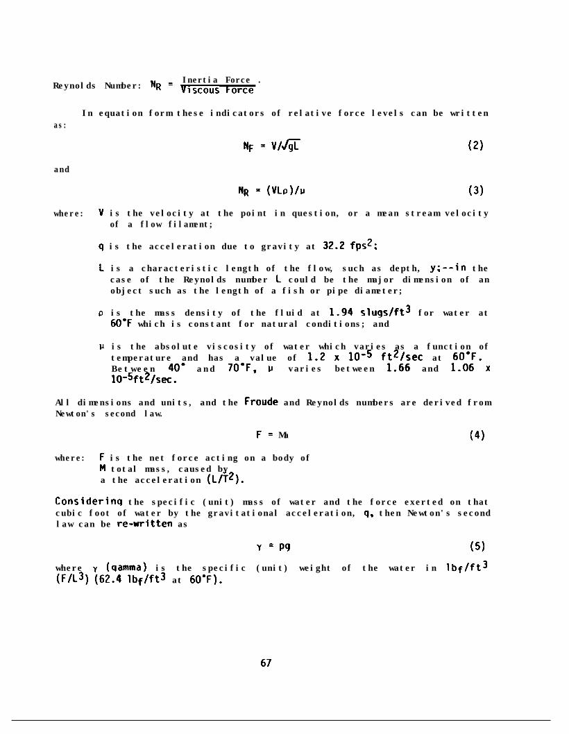
Inertia Force .Reynolds Number: NR = Viscous korce
In equation form these indicators of relative force levels can be writtenas:
and
RF = v/thjr (2)
NR = (~LP)/IJ (3)
where: V is the velocity at the point in question, or a mean stream velocityof a flow filament;
q is the acceleration due to gravity at 32.2 fps2;
L is a characteristic length of the flow, such as depth, y;--in thecase of the Reynolds number L could be the major dimension of anobject such as the length of a fish or pipe diameter;
P is the mass density of the fluid at 1.94 slugs/ft3 for water at6O'F which is constant for natural conditions; and
IJ is the absolute viscosity of water which varies as a function oftemperature and has a value of 1.2 x 10-S ft2/sec at 6O'F.Between 40' and 70.F, p varies between 1.66 and 1.06 xlo-6ft2/sec.
All dimensions and units, and the Froude and Reynolds numbers are derived fromNewton's second law.
F = Ma (4)
where: F is the net force acting on a body ofM total mass, caused bya the acceleration (L/T2).
Considerinq the specific (unit) mass of water and the force exerted on thatcubic foot of water by the gravitational acceleration, 9, then Newton's secondlaw can be re-written as
Y = P9 (5)
where y (qamma) is the specific (unit) weight of the water in lbf/ft3(F/L3) (62.4 lbf/ft3 at 6O'F).
67

The static pressure forces under water are governed by the depth, y andspecific weight, Y, so that p =to the atmosphere.
vy below the free surface of a stream exposed
This static pressure value changes as a function of depth and velocity.They are related to each other, and to the potential energy and their total,by the energy (Bernoulli equation) in Table 11.
Considering the depth and velocity of flow above a streambed, thentwo energy terms of (y + V2/2g) are called the specific energy of the flow.
the
At constant discharge (steady) through a cross-section of a river), thenas the flow moves downstream it will change depth and velocity (and specificenergy) as a function of changes in channel cross-section and slope.The equation one needs to relate flow velocity to cross-sectional area is thecontinuity (conservation of mass) equation.
Q = AV = AlVl = A2V2 = AiVi . . . (6)
where: Q is the flow in cubic feet per second (cfs);A is the cross-section area of top width, W, times mean depth, y; andV is the mean velocity through cross-section A.
Subscripts 1, 2, and i denote stations or cross-sections along the river.Obviously, as depth increases, area increases, and therefore velocitydecreases to keep the discharge constant.velocity in the downstrezmn direction,
In terms of changes in depth andthe flow is classified as gradually or
rapidly varying flow, or non-uniform. If there were no changes in depth orvelocity downstream of a reference cross-section (station) the flow would beclassified as uniform. For a constant discharge at a station, the flow isclassified as steady (or unsteady for Q # C).
Relationships Between Flow Conditions and Fish Speeds
A general description of stream flow, fish speeds and applicableequations from Table 11 are presented next. In a natural stream the velocityprofile throughout the depth can be represented by the conditions shown inFig. 39. As can be seen in Fig. 39, the rate of change in velocity (u) overdepth (y) (the velocity gradient) changes as a function of depth. It is mostpronounced near the stream bed where the local velocities may be irregularwhen vortices are being shed behind large roughness elements. The velocitygradient (du/dy) in association with viscosity governs the shear stress on thebed particles (Table 11, component 1).
68

Table 11. Sunnlary of equations used in the analysis of fish and flowrelationship;.
cQOonmt Equetion
0) uatw VlSCws 1 l udu/dy
Forces
‘*I E” shwrto - VRsI
(3) Enrcp -111Atirtlonsh1m EqlJet1en
y l vwg l 2 l t
(4) SoaiflcEnrcg
Es l y l V212g
w☺wmd☺bwe
Itry Bed.
(5) ~~;;~ity 0 l AV
Q l A,V,= A*V*..
(6) “n;~g v - (1.49/nPSe"*
A~iICJtIons
VlSCous forces. Reynoldsstrossos. bowdJry shmrstress. sed14ttmns-port. velocity protllc.
6nnir1ze Inspmningweb. (SW note Jar6 m: 5.)
Emvgy lost In flw;chJnges In deem. Dras-SUIV. kimtic emqyJnd Position
ktedning sum offlw. rlwther flw 1sdeam Jnd slaminp(r*ritIyi velalty).-or rue JW SnklisuDercrItiui).
used In cmjUnct
Ia 5
.Ion with
Def1nct10n of Terms-(Dimensions: corce; &ngth; IIr; (1ssi
shew stress (force/unit rm). (F/l*,
r1scesity (n/l*)
laai rclalty (L/Ii 4t depth. y
SDaiflC mefpht of Yter (F/L')
hydreu1tc radius of chemel (Li
slam of allergy gmdlmt (L/L)
wm (Limen velalty over 4eoth (y), (L/T)
efurgy Jquktlaa tocAlal-14tewter surfece pm- A l cross-rectioml J~J of ciunml (L*)flla. sugc-dlscneqere14t1ons. etc.
v l men velocity of flw (L/l)
To demmln mnf do- n l mirlc~i roqhmss coefflclmt~_ --crtybrsedon cluncter-fstics of CJmmel Se- slooe of energy graw lfm fra
Bermuill Eawtion
MO-: The slooe of me chenmi bed (SiJ rcDresents the mte of crlelQe (gredienti of the potent1ei energy of
mefla4ewetordnu. or me grev1t4tlomi Jttratlm ecnly on the flw. IAWn YteC surfrcerlooe (SJ is prreilel to the sleoe of the chenmi bed (Sb) they are equei to the slooe of he emqy
gndlrnt (5,). l nd UN fla 1s chsslfled JS unlfom. mml flw rklch rerciy occur in mturrl.
lrr49uirr chumeir. exCCOt on fi4tter gredlents with flm gnlm4 bed uterirls.
(7)
(8)
(9)
(10)
VoialProfllo u/~'S.75(log y/k)+&5
1
For locei velocity:
For-n strem veiaftyv/u.-S.lylog V,/k)*s.O
.o-9 Ute drag:Forms F, l $,+/2
Skin (frlCtlenJ drq:Ff - CcJAsW2
Tot~i drag:*Ft - Ct”A,V It
pacredP - WFtJ
4nwFOR@
Fe - dJW2-9)
Oetemim velocitynJIlmtmhlb flrh mst
0 = unitmss denisty (M/L')
sul= new St-. u.=sh~rstmss velocity. ir(L/T)
rclrtd to size ef bed-WrL mughness
k l height of dmlmnt bad rteriri (L)
y,- mn death of flw (Li
c4icul4te ralstenceforce In velalty field
F, - make force (F), ~mswre
(such JS In culvert flwi C, l wkedreg coefficientta flsll mcmtup-strem; CItiPte soaies
ALP - fmntrl protected WM of
rbllity to bare-e high Cf - friction dreg coefficientreiaIty rqions. As = rurfrce M-M of fish (L*)
Ct = tot41 drag coefficient
Ffsl) ower m?cas~ry topm#ei fish at 41c1n
P . (LFITi
reloclty. v.
Attrectlon Of fish byflws. 1-t force if
☺CU. mat force Of
fish Strikill9 ObJcCtS.
F-0 srntu force (FJnv2- second velocity cond3tIon
V,= inltiri velocity condltlon
V, ad d2 am ln the same dlmctlon.
'kc cut for mre 4etetled uoi4~tion.
flSh (L*i

Figure 39. Nomenclature for velocity profile.
The shear stress on the boundary o can be calculated from
=0 = TRSe (7)
This shear stress is the mean value in the cross section with a hydraulicradius of R and an energy slope of S . Assuming that "normal" flowconditions exist (see note after Item 6, Table 11 ), and the water surfaceis parallel to the bed, obviously a steeper slope will cause a larger shearstress on the bed (assuning R is constant). But in reality, of course, for aconstant discharge, if the slope increases (Manning's equation) then hehydraulic radius will be reduced.
The hydraulic radius is defined by the ratio of the flow area (A) to thecontact surface between the water and the streanbed (wetted perimeter, P) as
Hydraulic Radius (R) = Flow Area (A)
Wetted Perimeter (P)(8)
In a wide channel the mean depth (yo) can be substituted for the hydraulicradius such that
'CO = YY& 0)
The change in depth (yo) must be calculated at various sections along thechannel using the energy equation and the continuity or Manning's equation.
70

Obviously, assuming that y. remains constant (Q increases) as Seincreases, the boundary shear stress increases and the size of the surficialbed material becomes larqer. Locally, such as where flow concentrates alonqthe outside bank of a 90' bend, shear stress on the boundary increases andbecomes about 60 to 100 percent larger than the mean value in the bend.
Also, as slope increases and depth decreases, velocity must increaseaccording to the continuity equation. As a result (for Q = constant) thespecific energy in the flow changes. The kinetic energy term becomes moreimportant as the flow becomes shallower and follows the relationship shown inthe sketch of the specific energy in Table 11.
The single line in the specific energy (depth, y, plus velocity head,V*/Zg) diagram is for one flow. As depth y changes, velocity is calculatedfrom the continuity equation to obtain the kinetic energy. Larger dischargeswould form a series of specific energy diagrams to the right of the one inTable 11. The slope and hydraulic radius are not needed in thesecalculations --only the continuity equation and the channel cross-sectionalshape from which to determine area.
The Froude number of the flow
NF = v/fi (10)
chanqes inversely as a function of depth y.
When the soecific energy (y + V*/Zg) is a minimum, then NF = 1.0.This means that the flolwould move (VW =as critical flow WE
7less than critical willclassified as supercrit icritical, depth becomesless than critical, and
is moving at just the speed at which a surface wavein that depth of water. This condition is classified
NF = l.O., flowing at critical depth, yc. Depthshave velocities greater than critical velocity and arecal flow conditions. When water depth increases abovethe dominant energy term (pressure), velocities arethese flow conditions are classified as subcritical.
One other important aspect relates the state of flow to the Froudenumber. At a control point, such as a spillway, fishway weir, or waterfallwith a pool upstream, the water surface profile is calculated from the controlupstream (subcritical flow-- a wave will travel upstream NF < 1.0). On thedownstream side of the crest, the depth will try to decrease to some newnormal depth for that bed slope (SW = Sb = Se). The water surface profilemust be calculated from the crest in a downstream direction for supercriticalflow (a wave caused by a disturbance will travel downstream). The velocity ofthe water is greater than that of a wave at that depth and NF is greater than1.0. Water surface profiles when the flow state is subcritical are classifiedas mild and as steep when the flow is supercritical.
71

The momentum force applies to the strength of a jet (e.g., fishladderattraction flow) to sustain itself after issuing into a pool or flowingstream.
F, = PQ& - VI) (11)It can be readily visualized that when a jet is issuing from a chamber
into a quiet pool, then the jet velocity (VI) is reduced to essentially zeroat some point downstream (V2) by entrainment of flow and viscous forces (shear
. stress between the edge of the jet and the quiet water). A larger discharge
E)zeroissuing at the same velocity would require a greater distance to bring V2
.
If a jet is issuing into a flowing stream, then the distance throughwhich the jet will be attractive will depend on its direction with respect tothe direction of the stream and the relative velocity of the jet to thestream. The attraction of upstream migrating salmonids to high velocity (andthus high momentum) jets is discussed in a later section in which a new methodfor the analysis of attraction flows is developed. An analytical model forthe comparison of fish energy expenditures using different modes of fishwaypassage is developed in the next section.
72

A CONCEPTUAL, ANALYTICAL MODEL OF THE ENERGYREQUIREMENTS OF ASCENDING FISH
The following is an analysis of energy requirements for fish migratingupstream past velocity and elevation barriers. Three different cases areconsidered: (1) swimming through ports in a fish ladder; (2) swimming up asloping channel such as a spillway or waterfall face, chute, or culvert; and(3) leaping over a waterfall or a weir.
Basic Fluid Mechanics and Fish Capabilities
The total energy required to satisfy the above conditions is due to acombination of pressure forces and drag forces. The energy requirement of thefish to ascend in elevation, due to the pressure force alone, is the same asthe increase in potential energy (Ziemer and Behlke, 1966).
EP = WAH (1)
where: EIi
= the energy requirement due to the pressure force, ft-lb;= the weiqht of the fish. lb; and
AH = the
Energy requi
where: D = thed = the
difierence in the water surface elevation, ft.
rements caused by drag forces are calculated from
Ed = Dd
drag force, lb; anddistance through which the drag force acts, ft.
The drag force on the fish can be calculated by the standard equation
D= CdA P(vf)*/2
where: D = the drag force on the fish, lb;Cd = the drag coefficient, dimensionless;P = the density of the fluid, for water at normal
1.94 slugs/ft3;temperature,
Vf = the velocity of the fish relative to surroundA = a certain drag-related area.
ing water; and
(2)
(3)
For most fluid mechanics research the area, A, is defined as the frontalsilhouetted area viewed in the direction of flow. Researchers have useddifferent definitions for the area which has a profound effect on the value ofdrag coefficient, Cd. Ziemer and Behlke (1966) used A = L*, where L is thelength of the fish. Weihs (1974) defined it as the total surface area of thefish. He mentioned that experimental data by Lighthill (1971), and Webb
73

(1971) showed that the drag of swimming fish is increased by a factor ofapproximately three times the value for a rigid body. Estimated of muscularefficiencies by Alexander (1967) led to the same conclusion of increased dragduring active swinaning. When a fish is swimming its surface area remains thesame,whiletefficienciesbyAlexander(1967)ledtothesaneconclusionofincreaseddragduring active swimming. When a fish is swimming its surface area remains thesame, while the projected frontal area can be expected to increase by aboutthree times. For an adult salmon 22 inches long, 4.4 inches deep, and 2.5inches wide, the frontal area is estimated to be 11.0 in2 or 0.076 ft2 whilein a restingabout 0.23 ftk
osition. When swimming, the frontal area, A, will increase to.
In general, the length to height ratio of a fish is 5 and length to widthis 0.8. The frontal area, A, is estimated to be equal to a rectangle of theheight times the width. The rectangular area is slightly larger than theactual frontal area.
A = HW
A = (L/5) (L/8.8)
A = 0.0227 L2 (4)
From this equation the frontal area of different sizes of fish can becalculated as follows:
Table 12. Frontal area as a function of fish length whenresting and swinxning
Length, L Frontal Area, ft2
At restinch ft.
When swimmingAr = 0.0227 L2 As = 3Ar = 0.0682 L2
05126 1'0
0.0057 0.017
18 1:50.0227 0.0680.0511 0.153
22 1.8 0.0764 0.22924
22::0.0909 0.273
30 0.1420 0.426
74

The general shape of a fish is close to that of a two-dimensionalelliptical airfoil. Daily and Harleman (1966) indicate for a two-dimensionalelliptical airfoil with an aspect ratio (length to height) of 5, Cd is 0.06 ata Reynolds number of 4 x 10⁵. The Reynolds number is defined as VfL/$ , whereL is a characteristic dimension such as fish length, and 3 is kinematicviscosity. At a temperature of 50 degrees Fahrenheit, the kinematic viscosityof water is 1.4 x 10-S ft2/sec. The fish speed, Vf, can be divided into threeclasses of sustained, prolonged, and burst for which upper values were listedearlier in Table 9. A surmnary of selected values is given in Table 13.
Table 13. Selected Values of Burst Speeds (fps)
Lower Limit Upper Limit(Maintained for (Maintained for
15 seconds) 6 seconds)
Chinook 10.8 22.4Steelhead 13.7 26.5Coho 10.6 21.5Chun (or Pink) 7.7 16.0Approximate Averages 11 .o 22.0
Brett (1963) claimed that the power required by a fish when swimming isabout 50 percent of the power recorded in dead fish drag tests. However, thedrag force during swimming was not measured directly. Brett's conclusion wasbased on oxygen consumption of fish measured by the rate of oxygen depletionin circulating water, and the oxygen-debt in fish was determined by tracingthe recovery rate under resting conditions. These procedures may not be anaccurate determination of swimming power. It is known that protein can beused as an energy source when in a lack of oxygen situation.
Swinning Through a Port
When a fish swims through a submerged port it encounters both thepressure force and the drag force. In most fish ladders the water surfacedrop through each port is usually fixed at one foot. If the weight of a fishis assumed to be 4.0 lbs, the energy required to swim against one foot ofdifference in the water surface elevations is
EP =WAH= (4)(l) = 4 ft-lb
assuming no use of its air sack for buoyancy.
75

ABC - CONE OF CONSTANT VELOClfYV-8 rp8
DAC - CONE OF MMNG, VELOCITV CHANGESmay’ 8 10s ALONG AC to0 for ALONG AD
Figure 40. Velocity distribution downstream of a port.
For a 15-inch square port, the velocity distribution downstream of theport is shown in Fig. 40 (Albertson, 1950). The average water velocity at astreamlined port opening with one foot of head drop is about 8 fps.Therefore, the fish must swim through a port at a speed higher than 8 fps.
Assuming the fish swims at the lower average burst speed of Vf = 11 fps,the drag force on the fish is
D = CdA p &)2/z
D = (0.06)(0.23)(1.94)(11)2/2 = 1.61 lb.
76
(5)

The relative position from which fish start to dart through the port is notalways the same. They usually move close to the port to take a visual fixand/or to sense the velocity pattern before darting through the port.Sometimes they swim into the main jet stream and are pushed downstream beforethey can regain their orientation, and then they burst through the port. Forthis estimate it is assumed that fish start to dart from a location two feetdownstream. The two-foot distance is measured from the port to the masscenter of the fish. Therefore, the energy requirement due to the drag force is
Ed = Dd = (1.61)(2) = 3.22 ft-lb (6)
The total energy requirement of a four-pound fish to swim through a port witha one-foot pool surface drop is
ET = Ep + Ed = 4 + 3.22 = 7.22 ft-lb (7)
Since the cone of constant velocity extends about 7.5 feet downstream,the fish encounters essentially a constant downstream velocity of 8 fps duringthe two-foot swim through the port. If the fish swims at a relative velocitywith respect to the surrounding water at 11 fps upstream, then the fish speedwith respect to the fish ladder is only 3 fps upstream. It would take about2 ft/3 fps = 0.67 seconds to swim through a port. Using similar calculationsit would take ET = 3.61 ft-lb for the same four-pound fish to swim through aport with 0.5 feet of drop between pools.ft-lb.
At 2.0 feet of drop ET = 14.45
Swirrming Up a Sloping Channel
Examples of flow down an open channel, classified as a "velocity chute"are shown in Fig. 41. When a fish is swimming up such a channel, the depth ofwater at the head and at the tail of fish are assumed to be the same. Thus,there is no difference in pressure force in this motion, and the energyrequirement to overcome the pressure difference is zero. So the total energyrequirement is due to the drag force only and ET = Ed. Near the top of thevelocity chute there is a rapid decrease in velocity as the fish nears theupstream pool. For these calculations it is assumed that the flow is atnormal depth throughout the length of the slope.
f o o t .
Take the example of a wide ramp with a normal water depth yn = 1.0The hydraulic radius of a wide channel is approximately equal to the
depth of flow. Manning's equation (Daily and Harleman, 1966) can be used tocalculate the friction energy loss on the chute as
VW = (1.49/n) (R) 2/3 (se)112 (8)
from which
Se = (n/1.49)2 (Vw)2/(R)4/3
77

/
ENERGY GRAOE LINE
, WATER SURFACE
WATER SURFACEA H
w STEEP SLOPE
Figure 41. Open channel flow.
where: VW = the average water velocity in the channel, fps;= Manning’s roughness coefficient;
g = the hydraulic radius, ft; and
Se = the slope of the energy grade line.
For a short chute, the entrance loss (0.2 (VY)2/2g) and the exit loss(1.0 (V,)2/2g) cannot be neglected. The energy equation of the flow is
AH = O** (v;/29) + se L t (Qg)
78

and substituting Eq. (9) for Se
AH = 1.2 (V;/2g) + (n/1.49)2 [(VW)2 / (R)4/31 L
= [l.2 + 2g (n/1.49)2 / R4/3 (L)] (Vt/2g)
or VW = [2g AH/(1.2 + 2g (n/1.49)2 / (R)4/3 L)]l/2
Using the customary units, g = 32.2 ft/sec2, then
VW (fps) = 8[ AH/(l.2+ 29.0 n2 / R4/3 L)]1/2
(10)
(11)
!W
For the case of normal depth, yn = R = 1 foot and n = 0.01, the watervelocity in the ramp can be calculated by Eq. (12) and is shown in Table 14for several elevation differences, AH, and channel slopes, SC.
Take the case for H = 1 foot, n = 0.01, and SC = l/100, the averagewater velocity in the ramp is 6.6 fps. If the fish swims at the lower burstspeed of 11 fps, it would take lOO/(ll.O - 6.6) = 100/4.4 = 23 seconds tocomplete the passage. This is longer than 15 seconds for which the fish canmaintain that speed. If it uses the maximum burst speed of 22 fps, it willtake 100/(22.0 - 6.6) = 100/15.4 = 6.5 seconds, which is slightly longerthan the 6 seconds that the fish can maintain its maximum speed. This may ormay not be, by definition, an impassable situation. In order to successfullypass longer chutes, the water velocity must be slower than the sustained speedwhich is defined as the speed fish can maintain for 200 minutes. An averagesustained speed for chinook and coho is 3.4 fps, 4.6 fps for steelhead, and2.6 fps for chum.
The situation for passage can be greatly improved if the roughnesscoefficient is increased, which is the basis of Denil's fishway. Forinstance, if the Manning's roughness coefficient is increased from 0.010 to0.030 or 0.05, the velocity in the ranp is much reduced.
For n = 0.03, AH = 1 foot, and SC = l/100, the average water velocity is4.1 fps. At the lower burst speed of 11.0 fps, it takes lOO/(ll - 4.1) =14.5 seconds which is slightly less than 15 seconds for which the fish canmaintain its speed. Therefore, this is a passable condition which some fishwill pass and some will not, depending on their condition.
For n = 0.03, AH = 2 feet, and SC = l/100, the water velocity is 4.5fps. At lower bursting speed of 11 fps, it takes 200/(11.0 - 4.5) = 31seconds which is longer than the fish can maintain (15 seconds). At a burstspeed of 22 fps, it takes 200/(22.0 - 4.5) = 12.9 seconds, which is alsolonger than 6.0 seconds for that speed. This is an impassable situation.However, it can be made passable by dividing it into two channels withAH = 1 foot, and with a resting pool at the midpoint.
79


In order to calculate the energy requirement for swimming up a steepramp, it is necessary to estimate the switmning speed of the fish. It can beassumed to vary from 1.2 times the water velocity up to a maximum burst speedof 27 fps. The energy requirement is E0.06, A =0.23 ft2, 3and P = 1.94 slug/ft ,
= Ed = Od = ACdA (Vf)2/2 d. For cd =
D = 0.0133 (Vf)2 (13)
ET = 0.0133 (Vf)2d (14)
The values of ET are listed in Table 15. For the case of fish drag whileswimming up a sloping channel, the channel (chute) length, L, equals distance,d.
In order to calculate the distance a fish can travel up a slopingchannel, it is necessary to obtain information on fatigue time versus speed,tf = f(Vf). It is preferable to have one equation covering the full range ofvelocity instead of a graphical solution.
For this sample calculation for an adult sockeye, the following relationhas been used:
Upper DescriptionFatigue Time Speed of Speed
tm, minutes k, set fps
200.00 12,0000.25 150.10 6
1E20:6
SustainedProlongedBurst
The following form of the equation may be used to describe the tf =Wf),
tf (set) = k/(Vf - V,)
where: tf = the fatigue time, seconds;
Vf = fish speed, fps; and
(15)
VO = upper sustained speed, fps, defined as the migration speedunder aerobic metabolism which does not cause fatigue. For adultsockeye, V, = 3.2 fps. The constant k (in feet) can be determinedfor prolonged and burst speeds
k = tf Of - V,)
81


For prolonged speed k = 15 (10.2 - 3.2) = 105.0 feet
For burst speed k = 6 (20.6 -3.2) = 104.4 feet
The k values are nearly constant and the average value is assumed to be105 feet. Therefore, the equation for adult sockeye is
tf (WC)= 105/ (Vf - 3.2) (16)
Eq. (16) is plotted on Fig. 42. The distance adult sockeye can swim is
L(ft) = (Vf - VW) t = (Vf - VW) 105Vf - 3.2
where VW = water velocity in the channel, fps. From Eq. (12)
VW (fps) = 8 AH 1 l/21.2 + 29 n2/R4/3 (L)
(17)
(18)
where L is the length of the channel which is equal to L = AH/S. For a longchannel, wherein friction is an important energy loss, the term 1.2 in Eq.WL which represents entrance and exit losses, can be neglected so that
VW (fps) = 8 LS
I
l/2
29 n2/R473 (L)
and
VW = (1.49/n) ( R2/3 (-(s)) (19)
where 1.49 = 8/e and the L cancels, yielding Manning's equation.
Assuming the fish migration velocity upstream is 20 percent greater thanthe downstream water velocity, then Vf = 1.2 VW, and Eq. (17) becomes
L (W = (0.2 VW) 1 l ,,‘“5w
3 . 2
L = 21VW
1.2 VW - 3.2 (20)
Combining Eq. (20) with Eq. (19), and letting R = 1 ft as before, yields
83

1.49fi
L (ft) = 21n
1.2 + - 3.2
45 1= 31.3 -n 1.79& _ 3 2
n .
= 31.3 & nn 1.79fi - 3.2 n
L= 31.s1.798 - 3.2 n (21)
where V, = 3.2, the upper sustained speed, and the hydraulic radius R = 1foot.
Distance values for adult sockeye are listed in Table 16, and plotted in Fig.43. Re-arranged as a function of the upper sustained speed, Vo, in Eq. (21)is
1.796 - V. n = [31.1&]
1.796 = [31.36]
/L
/L + V, n
or, vo n = 1.79&-
when R = 1, and the distance a-
c31.31153 /L (22)
fish can swim on a particular slope becomesinfinity when V,n -+ 1.79 6. Thus, stronger fish can swim farther, and allfish can swim farther as the channel roughness is increased.
Recall that this solution was for a wide channel in which R = y = 1 foot.The more general equation for the swimming distance before tiring,for any depth of flow, y, and hydraulic radius, R, would be
L (ft) = 21 (1.49/n) (R)2/3 (S)1/2
1.2 (1.49/n) (R)2/3 S1/2 - 3.2
= 31.3 (R)2/3 (S)1/2
1.79 (R)2/3 (S)1/2 - 3.2 n
84

Table 16. Distance against velocity for adult sockeye swimming up aninclined plane using Eq. (21)
Manning's VO” SlopeRoughness 1.79n
n = 3.2 n S 6 1.79JT - Van 31.36
0.011 0.032 K%pM&
0:0400.050
iEE .
0.02 0.064 EEi0:0200.030
: l Ep;; .
0.03 0.096 !E~.0.0200.0300.0400.050
:-YE .
0.04 0.128 0.0050 .OlO0.0200.0300.0400.0500.0700.100
0.05 0.160 0.0050.0100.0200.0300 -0400.0500.0700.100
0.07070.1000
ix!Cpg
pg;.
c-0$5maSL:”25
EE.!?%z
0: 35800.4000
iE8:.
tu-J’,aaWW
t2.L“P
tE%pgpgp;:;. .VEp;“0:;;;;pm;.
0.00140.0510
:- ;;:i0:23000.27200.34600.4380
0.24000.31400.4060
2.213 23.43.130 ?1.3
4.4305.420 :E6.260 19:27.000 19.0
KE . :iE .
35.427.2
cm23.422.0
72.337.728.225.323.923.021.921.2
61.435.429.827.225.723.922.6
‘CL36:l31.6
;:-:24:4
85

70
so
rl 1I 'I 1 111 I I I - ;. ! : 7: : ..!m i \I I
1
’ i :!I:‘!
* n-o.05 ’’+‘\I
i y:Li
I j iiiiii
t
- lot Anm@a(1lnahvuocuYio~lyoIaunrnnr~.(2lLmmr-mnelm32~(31 Om@U’ d mlu b 1.0 IL h l r(dr M 10 R-Ycl.0 (1.
0 I i Ill! 1 1 ;li:::i0.005 0.01 0.015
SLOPE OF CHANNEL. s0:1
Fig. 43. Distance that adult sockeye can swim before tiringas a function of channel roughness (n) and slope (SC).
86

26
24
22
2c
111cn
E’1 16
5
; 14
%0 11F<u.
l(
e
t
I
+ ADULT SOCKEYEFROY J. F. ORSBORN’S FISHERIESNOTE TABLE 2
0 YOUNG SOCKEYE16.6 cm (7.4 m) TOTAL LENGTH55.2 gm (0.12 lb) Al 15%FAOU BRETT. J. R. 1963 WIG 4)
FOR ADULT SOCKEYE
1.15t (mmutosl- -
“I‘ v,
i i 6 i 10 t-2 ;4V,. FISH VELOCITY. 10s
Fig. 42. Sockeye swimming velocity related to fatigue time.
87

In the form of Eq. 22,
"0" = 1.79 (R)2/3 (S)1/2 - 131.3 (R)2/3 (S)l/23 / L (23)
when the fish velocity,Vf, is 20% greater than the mean water velocity. Theentrance and exit energy losses are neglected by assuming they are smallcompared with the channel friction loss. All these losses could be accounted
. for by using Eq. (12). and repeating the development of Eq. (23).
Leaping Over a Waterfall or Weir
During leaping, the fish passes through air rather than dense water. Ata temperature of 50 degrees Fahrenheit, the density of air is 0.00242slugs/ft3 which is 800 times lighter than water (1.94 slugs/ft3). The dragforce in the air becomes negligible even at maximum burst speed. The totalenergy requirement of leaping is solely to compensate for the potential energyincrease at the new elevation, ET = ESp = WAH. For a one-foot drop andfour-pound fish, the energy requirement is 4 ft-lb. In order to reach the new
the fish must have a vertical velocity component ofwhen it jumps from the lower quiet pool without a
Generally the initial leaping velocity is at an angle about 60to 70 degrees to the horizontal as shown in Fig. 44.
% -----IIII
\-
t
II’ 8 II
1 vy+~-VfSin 8
LAYVX
Fig. 44. Angle of velocity of leaping from a quiet pool.
The velocity of the fish Vf = Vy sin 8 =Jm/sin 8. The energyfor leaping, ET = Ep is
88

EP = 1/2mv2, = 112 (w/9) ("f) 2 = (W/(29)) (&CJY!Z/sin e)2
= (w/(29)) (29 AH/sin2 0)
= W ( AH/sin2 e)
For a fish with W = 4 lb and c1= 60 degrees:
FP = 4 [ A H/(sin260')] = 5.33~ H (ft-lb) (24)
The energy requirements in Table 17 are for leaping without any help fromthe standing wave in front of a waterfall or weir. When the jet is a freefall into water of sufficient depth (about 1.25 times the height of the falls)the fish consistently leap from a point where the pool surface bulges upward,known as a standing wave (Stuart, 1962). Apparently, fish have the instinctto take advantage of the upward current to help in leaping, thus reducingtheir energy requirements.
Table 17. Energy Requirement for Leaping from a Level Pool for a Four-PoundFish
Elevation EnergyDifference Required
AH E = 5.33 AHft ft-lb
1 5.3
510.716.0
4 21.35 26.76 32.0
From tests on weir-type fish ladders by Hilliard (1983) in the AlbrookHydraulics Laboratory at Washington State University , the average standingwave rises above the pool surface by 0.024 4H for pool depths ranging from(0.80 to 1.50) 4H. The upward (vertical) water velocity, VW, at the standingwave due to the rising velocity of air bubbles, is approximately
VW = &g(O.O24) 4H = 1.24m (25)
With this upward velocity component taken into consideration, thevertical fish velocity, Vf relative to the surrounding water is:
89

"f = vy - VW
Vf = 8m - 1.24fiH
Vf = 6.76 KH (26)
The energy requirement for vertical leaping is:
E = W(Vf)2/29
E = 2.84 AH (27)
There is an upstream (horizontal) water velocity component in a standingwave which also helps the fish leap (Stuart, 1962; Aaserude, 1984). Theleaping angle, 8 , can be increased to about 75 degrees for a standing wave incomparison to the 60-degree angle used in a still pool. The energyrequirement for leaping from a standing wave is:
E = W (Vf)2/2g (l/sin20 )
E = 3.04 AH (28)
Energy values for the four-pound example fish are listed in Table 18. Amore complete hydrodynamic analysis of the leaping mode is presented in Part 2of this report (Aaserude and Orsborn, 1985).
Table 18. Energy requirement for leaping from a standing wavefor a four-pound fish
ElevationDifference
EnergyRequired
E = 3.04AH(ft-lb)
: ii::34 l?:
s15:218.2
90

Sunmary of Energy Requirements for Fish to AscendThrough Ports, Up Chutes or Over Weirs
A comparison of the energy required for fish to ascend elevations of 1 to6 feet by various modes--through a port, up a chute, or by leaping, ispresented in Table 19 for the assumed flow and fish conditions. As discussed,these modes of transportation from one pool of a fishladder to another requiredifferent amounts of energy expenditure. The analysis does not solve thegeneral equations for all the variables (such as different fish species), butit does define the concepts of the model. Further work in this area of fishcapabilities should be developed.
Certain conclusions are obvious from the values in Table 19.
l Swimming up a chute takes less energy only for elevation differencesof two feet or less and on a l/l (45 ) channel slope.
l Leaping from a quiet pool takes a little less energy, but about thesame amount that swimming through a port does, up to H = 2 ft.
l Leaping from a standing wave decreases the energy requirement to about57 percent of the energy required to leap from a quiet pool, but thisis a function of the amount of air rising in the standing wave, andthus the roughness of the weir crest and the height of the fall.
. For a comparative example, when AH = 4 feet in Table 19, swimming up aranp 400 feet long at a 1 percent grade requires about 10 times as muchenergy as swimming through a port or leaping the 4 feet from a quietpool. But leaping 4 feet from a standing wave requires only 4.6 percentof the energy to swim up a 400-foot ramp on a 1 percent slope, and only42 percent of the energy required to swim through a port. One mustrealize that this is a comparative analysis and that port fishways arenot designed with four-foot drops between pools, because of theprohibitive velocities through the ports.
The application of this biomechanical analysis to fish passage problemsin culverts, up chutes, and through various fishway openings (port, slot andweir), should be developed for other variables such as species, port size andshape, slot opening and flow depth, and weir flow.
91

Table 19. Summary of energy requirements of a four-pound ascending fishswimming through a port, up a chute, and leaping an equivalentheight.
LeapElevation Swim From From
Difference Through Swim :I;,; Ramp Level StandingAH Ports l/loo l/l Pool Wave
Table 15 Table 17 Table 18
ft ft-lb ft-lb ft-lb ft-lb ft-lb ft-lb
1
21:7 1tf
50.3 13.0 1.6
1E 16:0
3.0
5 121 -- .o 44.0 -- 6.1 -- 6.1 9.1
---------------------------------------
4 28.9 264 .O 134.4 23.5 21.3 12.2
- - - - - - - - - - - - - - - - - - - - - - - - - - - - - - - - - - - - - - -
5 36.1 -- 26.7 15.26 43.3 413.4 25010 3816 32.0 18.2
92

THE ROLES OF STIMULUS, RESPONSE, AND STRESS INTHE DESIGN OF FISH PASSAGE STRUCTURES
Introduction
Two primary considerations need to be addressed when discussing fishpassage structures. One is the biology of the fish and how the fish'sadaptations prepare it for obstacles encountered during the spawning run.Secondly, if a fish passage structure is to aid upstream migration, itshould do so without causing additional stressing factors to the upstreammovements of the fish.
Hoar (1958) addresses the first concern and categorizes the fish, itsenvironment and how it deals with that environment into a series of stimuliand responses. Responses may be physiological or behavioral with behaviordefined by Tinbergen (1951) as the "total movements of the intact animal."An ethological approach (i.e., objective analysis) to fish behavior will beused and explanations of behavior may be in terms of immediate cause-effectrelations, or evolutionary adaptations.
Hoar (1958) describes behavior as a series of fixed stereotypedmovements. These movements can be the result of a specific internalphysiological state or in response to definite factors (termed "releasers")from the external environment. Normally, there is a steering or orientingcomponent to the movement. The term "appetitive behavior" refers toextended activity which frequently precedes the goal situation. Thisbehavior may be described as an "urge" or "appetite".
Three major levels of movements can be described:1. drive--" the complex of internal and external states and stimuli
leading to a given behavior (Thorpe, 1951; Baerends, 1957, as citedin Hoar, 1958);
2. appetitive behavior;3. the consummatory act.
The series of behavioral movements is set in motion by what Hoar terms"specific releasers" and they are then guided by conditions in theenvironment. Behavior is a very plastic phenomenon and, depending oncircumstances, may not proceed directly from the drive to the consummatoryact. Various factors are responsible for the plasticity of instinctivebehavior:
1. The intensity of movements may vary in relation to the amount ofinformation received;
2. releaser information is sometimes received through more than onesensory channel; and
3. there may be a change in the intensity of internal motivation.
93

When two incompatible instincts are simultaneously aroused, or when thenormal releaser disappears before the behavior pattern is completed,inappropriate, illogical behavior patterns may result. These are termed"displacement activities." If a strong disturbance occurs, the behaviormight regress back to an earlier stage in the hierarchical organization.This condition is known as *fall back."
Within this context, the behavior of a fish negotiating fish passagestructures will be discussed, including specific stimulatory or inhibitoryfactors which should be minimized in the design of passage structures.
Table 20 lists various passage structure and environmental componentswhich contribute to the bio-hydraulic conditions present in a fishway.Also listed are factors which could be considered stimuli, inhibitors, andstressors.
Stimulus and Response
Behavioral patterns of animals can be characterized as a series ofresponses to stimuli, both external and internal. In the specific case ofthe upstream migrations of adult salmonids, numerous environmental factorsare involved. These factors and the responses they elicit in migrating fishmust be recognized if man-made structures are to assist fish (or at leastnot hinder them) in overcoming natural and artificial obstacles encounteredin river systems. A general discussion of environmental factors which mayserve as potential stimuli will be followed by a more specific treatment ofa pool:weir fish ladder design.
Stuart (1962) in studies on potential stimuli identified direction andstrength of flow as directing and releasing stimuli. The naturalorientation of movement of a fish is to the direction of the flow. Athreshold level of flow is required to initiate and maintain orientation andmovement. These threshold levels vary with the size of fish and presumablyalso vary with species. Sudden increases in flow can initiate upstreammovement (Elson, 1939; Hayes, 1953). However,inhibitory. In general,
excess flow may bean increase in the rate of flow stimulates greater
activity in the fish (Banks, 1969).
The implications for fish passage design are obvious. Sufficient flowmust be maintained in order to attract the fish to the pass and to stimulatethe fish to move through the fishway. Extreme flows must be avoided becauseof their inhibitory effect on upstream movement.
Temperature serves as both a stimulatory and inhibitory factor. Withintheir preferred temperature range, juvenile coho and Atlantic salmonexhibited the greatest frequency of leaping behavior (Symons, 1978). Fisherand Elson (1950) demonstrated that a species' preferred temperature range isalso the temperature of maximum response to an external stimulus. Maximumcruising speeds are also exhibited within the selected temperature range
94

Table 20 .--Environmental passage conditions for a fishway unit
Items Passage Conditions
Variables Contritpting toHydraulic Conditions in aFish Passage Structure
External Stimuli
Internal Stimuli
Inhibitory Factors
'Undue' Stress Sources
1. Watera. Flow e. Entrained Airb. Velocityc. Turbulence
f. Temperature
d. Momentum;- ;;r;:try
.
2. Passa e Opening (Weir, Port, Channel, Slot)a. Di 3ference in pool elevationsb. Widthc. Type of openingd. Jet geometre. Flow contra Y
3. LaowcDrp;;ol (Fishway Entrance)
b: Pool geon?etryd. Entrained aire. Volume of chamber
c. Standing wave f. Baffles or otherstructures
1. Strength of standing wave/-et2. Location for standing wave jet3
::Attraction flow
z-
Vi/i;;1 perception
Boundaries7: Streamlining flow downstream
::Temperature
3.LightSeason
:-DelayLack of sufficient flowthrough
3: Excessive flowthrouoh4. Temperature barriers5. Excessive turbulence
1. Mechanical damage 5. Delay-2. ‘Hyperactivity ;. ;;;;",;;g
Temperature43: Water quality 8: Chanqes from natural
stream environment
95
Extreme temperatures may elicit avoidance behavior in fish if a temperaturefront is encountered, or may ultimately result in the death of the fish ifavoidance is impossible. Fishways should draw water from areas such thatwater within and exiting the fishways is at a similar temperature as thedownstream receiving water at the fishway entrance.
Specific information on the role of dissolved gases, trace minerals, andpH as stimuli is not available. Banks (1969) suggests that subtle effects onbehavior may prevent the ascent of fishways by fish acclimated to water ofdifferent characteristics than the water exiting the pass.
Light intensity appears to function also as both a stimulus and aninhibitor. Light is necessary for salmonids to ascend obstacles, but inunobstructed waters, a preference for darkness is seen (Banks, 1969).
The design of a pool:weir fish ladder takes advantage of the naturalleaping ability of salmonids. Stuart (1962) investigated the principalstimuli involved in leaping behavior and concluded that this behavior can bedirectly correlated with hydraulic conditions at natural waterfalls. Thespecific conditions involve a free-flowing jet plunging into a lower pool,resulting in the formation of a standing wave just downstream from the pointof impact. Fish consistently leapt from the crest of the standing wave.
For a given flow, the hydraulic conditions created at the base of theoverfall are dependent upon the height of the drop, and the water depth andbed geometry of the lower pool. The height of the drop controls the amountof kinetic energy and momentum contained in the jet. The depth of the lowerpool affects the location of the standing wave and velocity distribution inthe pool. The bed geometry affects stability of the location of thestanding wave and the streamlining of the flow downstream.
In Stuart's observations, the fish consistently jumped when the ratio ofkinetic to potential (depth) energies was high in the area just ahead of thefish. Fish are seemingly able to sense the "high energy front" and attempt toleap over it instead of swimming through it. Thus, the presence of the"energy front" may serve as a releaser to the leaping activity.methods used by the fish to detect the energy barrier are unknown.
However, the
The standing wave formed in the lower pool played a significant role inthe leaping activity. Hydraulic conditions exist which may, in themselves, beproviding a releasing stimulus.current.
The standing wave contains a strong upwardStuart conducted a series of experiments where balls of various
buoyancies were placed in the upstream pool. The balls were projected backupstream from the standing wave over the weir. This observation, inconjunction with the observation that all the fish initiated the leap fromthis area, led Stuart to conclude that the presence of such a wave was ofdefinite importance. (Results as shown in Report 2 of this project indicateair content is of importance to the formation of some "standing waves" due tothe rising bubble velocity.)
96

Another potential stimulus identified by Stuart was the impact caused bythe jet striking the lower pool. Fish which were 15 to 20 feet from the pointof such an impact could be stimulated to jump. Jumping activity could bestarted in a static pool by pouring water from a heiqht to the surface of thepool. The relative size of the fish responding to the apparent impactstimulus varied with the amount of water striking the surface. The impactstimulus (increase in noise level and/or the local velocity past the fish) mayserve to stimulate the fish to move forward in preparation for the leap.
A potential directing stimulus may be a visual perception of theenvironment. Stuart (1962) suggests that the fish may be able to perceive thecontrast between light and shade and thereby visually locate obstructioncrests by the contrast created between the sky and the barrier. Theorientation serves not only to locate the obstruction, but also to indicatethe height of the barrier. The suggestion of a visual, directing stimulus issupported by the facts that all leaping stopped at the onset of darkness andthat fish were able to leap over a barrier placed just above the weir crest.(Sighting was observed during tests at Johns Creek hatchery ladder asdiscussed in Report 2 of this project.)
Other components which could function as directing stimuli are factorssuch as color and the presence of boundaries. Fish orient toward surfacesof lighter colors. The shadings of walls and floors of ladder chambersrelative to incident light striking the water surface may affect theirorientation within the ladder and ultimately their movement through and outof the ladder. Fish also exhibit a natural tendency to follow boundariesthey encounter. Care must be taken in design so as to avoid leading edgesthat may direct fish into corners or other "dead ends."
Stresses
Mechanical Damage to Fish
Damage could result from sharp-edged structures within the passagestructure and on the fishway opening itself as shown in the Denil fishwayentrance in Fig. 7.problem.
Excessive turbulence within the chamber could magnify the
Hyperactivity
This term refers not only to excessive undirected behavior, but also toexcessive energy demands placed on the fish as it negotiates the fishway.
The end result of extreme hyperactivity is the death of the fish (Black,1958). To avoid undirected behavior, fish should be stimulated to keep
97
I

moving through the structure. A balance must be struck between keeping thefish moving and allowing them enough rest so as not to become exhausted.Sufficient, but not stagnant, resting opportunities should be provided.
Delay
A delay of the normal migration schedule of a run of fish may havevarying degrees of effects on the spawning success of these fish dependingon how much *slack time' has been built evolutionarily into a particular runof fish. If they enter the river system at an advanced stage of gonadalmaturation, even a small delay could result in spawning in unsuitable areasor death before spawning at all. Fish entering a system while they arestill *bright" may be less affected by delay, depending on how far up thesystem they have to travel before reaching their spawning grounds, and howlong they hold at the site before spawning. Nevertheless, delay isundesirable.
Delay could result from a number of factors. Two that are directlyrelated to fish passage structure design are: (1) inadequate attractionflow--if fish are unable to find the entrance, they may remain below thepass for extended periods of time; (2) lack of correct flow conditions tokeep fish moving through the pass. In this situation, fish would eitherremain in pools, or fall back, and possibly out of the passage structure.
Temperature
Salmonids, being cold-water species, are less tolerant of warmertemperatures. Higher temperatures increase oxygen demand as well as increasethe rate of all other metabolic functions and concurrently reduce the oxygen-carrying capacity of the water. Temperature stress also facilitates diseasespreading (Hunter et al., 1980). Temperature may also function as a barrierin a fishway. Water drawn from warmer upper levels of a reservoir would bein contrast to the receiving water at the entrance to the fishway and couldserve as a barrier as the fish encounter the temperature differential.
Water Quality
Oxygen and carbon dioxide concentrations should not prove to be a majorproblem in a fishway due to the mixing of the water as it travels through thefishway. These components are more a function of the incoming water than ofthe fishway itself. By taking care in locating the source of water for thefishway so as not to draw excessively warm or stagnant water, problems couldbe avoided.
98

Crowding
Higher biomass of fish per unit volume of water increases thepossibility of injury, disease, and stress due to hyperactivity. However,durinq peak spawning runs, avoidance of crowded conditions would be nearlyimpossible anywhere the natural upstream migration is interrupted by anytype of barrier. The best approach would be to provide sufficientattraction flows to eliminate delay below the passage structure and preventfish from "piling up.* Also, correct flow conditions should be providedwithin the pass to keep the fish moving up and out of the structure.Conservative designs tend to encourage delays and allow nonselective fishpassage.
Disease
Disease is more prevalent any time fish are crowded, stressed (due toany factor), physically damaged, and/or water quality is marginal. Byoptimizing correct conditions discussed above, the threat of disease can belessened.
99

SALMONID PREFERENCE FOR HIGHER VELOCITIESDURIN6 UPSTREAM MIGRATION
I ntroduction
In studies of fish passage facilities, and during other fieldinvestigations, it has been observed that upstream migrating salmonids tend tochoose the path with the highest velocity associated with the strongest flowfilament (largest amount of mass flow). This is a very important considera-tion in the attraction of fish to the entrances of fish ladders. Even thoughthis need has been realized and studied for many installations, fundamentalphysical relationships have not been developed between different velocitiesand the consistent choice of certain velocities by the fish.
In this section some principles of fluid mechanics have been applied todata reported in 1960 on the choice of the higher of two parallel attractionvelocities by several species of salmonids (Collins and Elling, 1960). Theiroriginal analysis tested the results statistically. The new analysis,involving the momentum differences between two attraction flows, yields aphysical basis for the design of attraction flows. The boundary solutions ofthe developed equations yield the upper limit of salmonid burst speed, and thelower limit is their most efficient sustained speed (about 2.3 fps, Brett,1965).
Test Data
Data on the preference of chinook salmon Oncorhynchus tshawytscha, silver1salmon 0. kisutch and steelhead trout Salm gaizdnsri for the higher of twovelocities in duplicate channels are presented in Table 21 from Collins andElling (1960). A report by Weaver (1963) gives details of the test apparatusand conditions at the Fisheries-Engineering Research Laboratory at BonnevilleDam in Washington.
The statistical analysis of the data in Table 21 showed significance onlyfor velocity ratios (Vl/V2) of almost 5:1, 4:1, and 3:l. There were toofew silver salmon to analyze statistically, but the test results are included.The data in Table 21 are average values for all tests, and replicate testswere run alternating the higher and lower velocities in both channels.
Testing was conducted on upstream migrating fish to observe theirpreference for higher velocities. The results of high velocity tests(6-8 fps) indicate that while both steelhead and the chinook sought highervelocities, the steelhead had greater stamina. During the highest velocitytests, 90 percent of the chinook chose the higher velocity channel, but only
I Popular name for coho used by Collins and Elling (1960).
100

26 of 51 (about 50 percent) traversed the 85-foot channel. Although only 75percent of the steelhead chose the higher velocity channel, 29 of the 31 (94percent) successfully neqotiated its full length.
Table 21. Velocity Combinations and Data Reduction for Analyzing theSelection of the Higher Velocity Channel by Silver and ChinookSalmon and Steelhead Trout (from Collins and Elling, 1960).
Test Average Percent of Fish ChoosingCondition Higher Velocity in All Tests
Silver(W
Chinookw
Steelhead6)
El8:0
z6:0
ii; iii 5;46 45 52
6.0 2.0 83 87 736.0 4.0 68 62 64
4.0 2.0 100 73 67
Special Test:
12.9 2.7 -- 90 76
Methods of Analysis
To expand the analysis of the data from Collins and Elling (1960), and todevelop some parametric relationships, several combinations of velocitymultiples, ratios, and differences were analyzed. It is important to considerthe velocity squared term, because it is indicative of both the drag andmomentum forces, on the fish and in the flow as discussed in the section onlocomotion and hydrodynamics.
Analysis to Include Chance
After examining the various combinations of velocity terms in the twochannels, it was decided that the differences in momentum between the twochannels and their average momentum should be set as boundary conditions onthe analysis as summarized in Table 22.
101


The choice between two velocities must be based on the relative level ofwhat is being sensed by the fish dnear the channel or fishway entrance. Moreimportantly, the difference in momentum forces ( 4pQV) is the dominant term,where: p is density, Q is flow, and V is mean velocity. Because flow is areatimes velocity, the momentum in the jets is represented by the velocitiessquared, and a fish attraction factor can be defined by
FAF = “* - v2211/2(Vl + v2)j 2
where the numerator represents the difference in attraction momentum and thedenominator represents the average (level of) momentum in the two jets. Thiscould be considered to be an indicator of the attractiveness of one jetdivided by the level of attractiveness in both jets.
If one plots these results as shown in Fig.45 they can be related to thestatistical analysis which was conducted by the researchers at the BonnevilleLaboratory. This is shown by noting that when the percent of fish choosingthe higher velocity is 50 percent, this is a chance situation with no realchoice being available. The fact that some samples fall below 50 percentdemonstrates that at lower values of the "fish attraction factor" (FAF) thereis more randomness in the choice. It should be noted again that the cohosamples were very small (five fish), and this accounts for the large amount ofscatter in their data points.
Some physical boundaries can be put on the graphs in Fig. 45 and theextreme values of Vl and V2. For example, the maximum burst speed forsteelhead is about 28 fps or 8.8 m/s. If Vl is the maximum fish speed and V2is equal to zero (pool condition) then the maximum FAF (X-scale) is 4.0. Ifone considers the lower limit (of V2) as being the most efficient velocity forenergy expenditure (about 2.3 fps) then the FAF term is about 3.4 (using Vl =28.0 fps). This is probably about the actual maximum conditions that could beachieved by steelhead and Atlantic salmon as shown by the long-dashed line inFig. 45 leading up to 100 percent of FAF = 3.4. An FAF = 2.8 is the bestvalue for chinook to guarantee maximum attraction. Other, less dynamicspecies would have their graphical relationships to the left of those shownfor chinook and steelhead, and lower limits on their FAF values.
Although the upper limits of the "fish attraction factors" were shown tocoincide with the maximum burst speed and most efficient minimum speed, thesame high level of FAF can be achieved with other velocity combinations. Forexample, a FAF = 2.7 can be achieved with Vl and V2 combinations of 22 and 4,15 and 3, and 10 and 2, respectively. The same analysis can be done forlower FAF values, but with less probability of success and more random choicesby the fish as shown in Fig. 45. The attraction flow velocity should, ofcourse, be less than the maximum burst speed of the species in question.
103

-bQ-4>
5W-0”
f
trm-zc
zmt-c,iii
2-iIArmV-LLcc0c,sY2
100
80
60
40
20
0
2.8 3.4
I I
I
-
0 S i l v e r
0 Chinook
V Steelhead
Maximum physical FAF = 3.4 I
1 2 3 3.4 4
Fish Attraction = V12 - v22Factor (FAF)
[f(Vl + V2)lZ
Figure 45. Choice of higher velocities by upstream migrating salmon andsteelhead related to momentum level in the attraction flows asdefined by the momentum difference divided by the averagemomentum in the two jets.
104

Sumary
The "fish attraction factor" makes it possible to design attraction flowsfor fishway entrances by knowing only the ambient velocity conditions (V2) andthe design species.
This physical-mathematical analysis of the selection of higher velocitieshas demonstrated boundary conditions governed by momentum, velocitydifferences, fish burst speed and minimum energy expenditure. Similarconditions can be established for other species based on their capabilities sothat more effective attraction flows can be designed. The application ofthis type of physical analysis, which matches fluid dynamic principles to fishlocomotion, has application to other problems where design criteria arelacking, such as the analysis of velocity and elevation barriers to upstreammigration, including culverts and waterfalls as discussed in Part 4 of thisproject report (Powers and Orsborn, 1985).
ouslyOther factors regarding the attraction of fish have been presented previ-in the chapter on fishway classification.
105

DESIGN SURVEY AND INTERVIEWS
Two different surveys were conducted to obtain information about currentfishway design practice:
(1) A questionnaire was mailed internationally to the organizations inTable 23; (NOTE: TABLES 23-27 BEGIN ON PA6EllO); and
(2) Personal interviews were held with fishway designers in BritishColumbia, Washington, and Oregon.
A copy of the mailed questionnaire is shown in Table 24. The questions usedto initiate discussion during the personal interviews are listed in Table 25.As a result of both the survey and the interviews we noticed that certaindesign information, based on documentation of both successes and problems,does not appear to be widely distributed or in common use. Applications ofcertain designs to certain species seem to be limited to a country or aregion. This "provincial" characteristic was noticed as a result of thenumerous comments and questionsSurvey (Table 24).
raised by respondents to the InternationalThree of the questions (3, 5, and 6) were addressed most
enthusiastically by the respondents.fishway designs and operation,
Their answers to questions 5 and 6 aboutand question 3 on references, are summarized in
Table 26 in that order because of their content.
Our survey and interview questions, plus those raised by respondents,have been categorized, paraphrased and summarized in Table 27. They areincluded as an overview of the types of questions which must be answeredcorrectly (within certain operational limits) when designing any fishway forparticular species. During our personal interviews, the responses to theconmnon questions were very similar to those we received from the internationalsurvey.
But, during the interviews we asked several other questions regardingfishway design which were not included in the international survey.
We have taken the following questions from Table 25 for furtherdiscussion:
7. How do you design for attraction velocity?
9. Have you made observations of fish passage at fishways? Formal orinformal? Documented?
11. Please discuss your general design philosophy regarding fishways.
106

Attraction Velocity
The need for attraction flow at the entrance to a fishway, its amount,orientation and its relationship to ambient flow conditions are all functionsof the particular site in question and its flow geometry during the upstreammigration season. The state-of-the-art in attraction flow is based primarilyon experience, but Bell (1984) gives a few criteria (also referred to byrespondents):
(1) Attraction velocities should be 4-8 fps, and preferably in the rangeof 8 fps, which agrees with the results of the tests by Collins andElling (1960); and
(2) Cross velocities should not exceed 2 fps.
If one considers the cross velocity of 2 fps to be competing velocityalmost parallel to the attraction velocity of 8 fps, the "Fish AttractionFactor* from Fig. 45 in the previous section would be
v12 - v22 *
FAF = [l/2 (Vl + v2) 32 = 2*4
This would mean that about 90-953 of the chinook would be attracted to the 8fps flow, but only 7580% of the steelhead, assuming velocity was the onlyfactor affecting their choice.
If fish are being attracted to a fishway from a quiet pool, the ambientvelocity is zero and there is no competition for the attractiveness of thefishway attraction flow (QAT in Fig. 1). As ambient flow becomes stronger(such as from a waterfall, spillway or powerhouse) then the relative strength(momentum = discharge times velocity) of the attraction flow becomes moreimportant. The angle of intersection is extremely important as well as therelative locations of the competing flows. Attraction flows which enter astronger strean at 90 are sheared off, and lose their attractiveness. Fishcan only find the fishway entrance by following the boundary until they sensethe attraction flow and turn directly into it.
Some persons interviewed felt that along a parallel boundary, such as astream bank, it is important to have a go-degree offset from which theattraction flow (QAT) can be issued parallel to the ambient flow of the stream(QS-QAT) parallel to the main stream and the bank. The offset cannot be wideenough to cause a large eddy in the ambient flow which can sever, dissipateand/or trap the attraction flow.
One of the main features of attraction flow mentioned in the interviewswas the necessity to counteract false attraction flow. This would be the caseboth in the eddy example mentioned above, and in upwelling in fishladder
107

chambers. Fish are erroneously stimulated to jump by flows which circulatealong the floor, and then up the side walls and in the corners. Baffling anddiagonal filling of the corners reduces these false attractions. During ourinterviews we cane across some unique attraction systems which included: (1)barrier fences and fire hoses; (2) a siphon hose to move impounded juvenilesupstrewl; and of course, (3) chemical signature homing to hatcheries whichdoes not require velocity for attraction.
Observations of Fish Passage
We asked this question to ascertain whether or not there was a body ofinformation on fish passage through fishways, other than the informationdeveloped during:
(1) Formal tests such as those conducted at the Corps of EngineersFisheries Engineering Laboratory at Bonneville; and
(2) Fish counts as conducted at most mainstem dams on the Columbia Riversystem dams which have upstream passage facilities.
We were seeking information which might lead to the development of abetter way to evaluate fish passage efficiency in terms of its efficiency inenergy expenditure, as well as documentation on observed actions and reactionsby various species. Some of the persons interviewed have observed passage infishways and offered these comments:
(1) There is not much well-documented information readily available onfish passage through fishways or over waterfalls;
(2) If given their choice, most species prefer to swim through low levelports as opposed to leaping over a weir (ostensibly to avoidexposure);
(3) Many observation reports have not been formalized, but are residingin agency files;
(4) It is "almost impossible" to get chum salmon to jump;
(5) If a weir drop is nine inches or less, chums will swim through theww;
(6) German brown trout in New England were successfully clearing avertical jump of 28 inches; and
(7) No formal tests have been conducted on pinks and chums to determinetheir swimning and passage capabilities.
108

It appears that there is a definite need for a more thorough analysis of"passage efficiency" through various types of fishways. The energyexpenditure of fish using different modes of upstream migration was developedin a previous section of this report and summarized in Table 19. Also, inPart 2 of this project report, a probability analysis of energy expenditurebased on successful and unsuccessful passage attempts at weirs of variousheights was presented. This type of statistical energy analysis holds promisefor a better method of evaluating fishway efficiency.
Design Philosophies
Most of the persons interviewed responded to question number 11 with astatement that usually followed this (average) line of reasoning: "Althou heach system is unique, there are certain criteria which can be applle ,al&only after careful planning." This may, at first glance, appear to benon-commital, generic or ultraconservative, but it reflects both the truestate-of-the-art for fishway design, and the judgment with which it should beapplied.
Although many natural passage sites have similar geometric and hydrauliccharacteristics, a uniqueness may exist in the combinations of species, thetiming of their runs, and/or the hydrologic characteristics of the site towhich the fish have become biologically attuned. Two points which wereemphasized throughout the interviews were to "keep it simple" and *it isbetter to err on the conservative side."
Some other aspects of design philosophy regarding fishways are:
(1) Use successful precedents as guides for new structures;
(2) Analyze each site for species, size, timing of runs, streamflow, sitegeometry, blending of flows and the existing attraction flow(s);
(3) Study the combination of factors during high water which adverselyaffects movement, and design for the worst combination of factors;
(4) Passage conditions at many sites are most strongly influenced byfluctuations in water levels (variations in the drop in water surfaceacross the barrier and through the ladder) as a function ofstreanflow;
(5) Field ob servations of the existing species should be made prior todesign;
(6) If all you do (in providing fish passage) is mitigate the knownaffects of a structure, then you (and the fish) lose; and
(7) We should be working to better understand, andnarrow passage "windows."
improve on, nature's
109

Table 23. List of Addresses for Fishway Design Questionnaire
United States of America
Atlantic Sea Run Salmon ConmrissionUniversity of MaineOrono, Maine
Mr. Don Clark24370 SE Strawberry DriveBoring, OR 97009
Mr. Mike DellGrant County PUDPO Box 878Ephrata, WA 98823
Mr. Carlos M. Fetterolf, Jr.Great Lakes Fisheries Commission1451 Green RoadAnn Arbor, MI 48105
Mr. Jack Fisher425 G Street, Suite 770Anchorage, AK 99501
Mr. Johanness LarsonAlden Research LaboratoriesWorcester Polytechnic InstituteHolden, MA 01520
Australia
Department of Fish and GameMelbourne, Victoria
Scotland
Nature Conservancy12 Hope TerraceEdinburgh
Maine Atlantic Salmon Federation36 Pitt StreetPortland, Maine
Mr. Ole MatisenFisheries Research InstituteUniversity of WashingtonSeattle, WA 98195
Mr. Dick NadeauU.S. Fish and Wildlife ServiceSRA-134-DAnchorage, AK 99507
Mr. Ben RizzoU.S. Fish and Wildlife ServiceOne Gateway CenterNewton Corner, MA 01258
Mr. Ted P. Vande SandeDepartment of Fish and Game1416 9th Street
Department of Fish and GameSydney, New South Wales
110

Table 23. (Continued)
Canada
Atlantic Salmon AssociationShell Tower1255 University StreetMontreal, Quebec
International Atlantic SalmonFoundation
PO Box 346Gaspe, Quebec
Ireland
Ministry of AgricultureSmall Farms and Fisheries Division2-4 Queen StreetBelfast
Mr. D. O'LearyElectricity Supply Board of IrelandStephen's Court, St. Stephen's GreenDublin 2
Japan
River and Lake DivisionFreshwater Fisheries Research LabHino-shi, Tokyo
Norway
Freshwater Fisheries ResearchDepartment
Inspektoren for ferskvannsfisketVollebek
Mr. James Walker andMr. G. 0. Taylor
Fish and Wildlife BranchMinistry of EnvironmentParliament BuildingsVictoria, B.C.
Department of LandsFisheries Division3C;;",a; Brugha Street
Sweden
Fishery Board of SwedenInstitute of Freshwater ResearchDrottningholm
Salmon Research InstituteAlvkarleo
111

Table 24. Fish Ladder Questionnaire for International Survey
Project Title: Development of New Concepts Albrook Hydraulics Laboratoryin Fish Ladder Design Washington State University
Pullman, WA 99164-3001 USA
1. Have you or your organization worked on the design or performance offishways? Yes No- -
2. What types?Slot Weir Weir and Port Oenil Steeppass Other type
3. What references did you use for your designs? (use back if needed)
4. Do you have project design reports, operation records, or other notes onfile? Yes No; Please send a few examples of these documents.
For these few exmles:
5. If Y O U were to build these ladders today, would you use the same designs?What modifications would you like to make?
6. For what species were these ladders built?
7. How well did the species use these ladders?
8. Do you have records or notes on performance evaluation? Yes Noyou do, please send some examples. We are particularly interekddesign modifications that were made after the ladder was in operation.
Ifin
9. Have you documented (e.g., photos or measurements) the leaping abilitiesof salmon or trout? Yes No-. We would appreciate being able toborrow these photos/notes.
Name Date
Address Phone
Thank you for your cooperation.Jack Orsborn and Walter Mih
112

Table 25. Discussion Topics for Personal Interviews* During The Period ofJune, 1982-September, 1984
1.
2.
3.
4.
5.
6.
7.
8.
9.
10.
11.
12.
13.
14. Do you have an inventory of your existing fishways?
Agency of firm.
Person(s) interviewed, discipline and experience
Types of fishway activity:
it:Design d. ResearchOperation e. All (a-d)
C. Review f. Other
Which major references do you use?
What is the relative size of fishways with which you deal?
L:Large SmallMedium 2 All
With which types of fishways do you have the most experience?Weir and pool
i: Orifice and poold. Slotted
C. Weir, orifice and pool f':Denil or Alaska SteeppassOther
How do you design for attraction velocity?
What data sources do you use for fish speeds, and swimming and leapingcapabilities?
Have you made observations of fish passage at fishways?Formal or informal? Documented?
Have you observed passage at natural barriers?
Please discuss your general design philosophy regarding fishways.
Can you provide examples of design, research or evaluation reports?
What are some names, addresses and phone ntiers of several other personswho are working on fishways?
l Persons interviewed are listed in the Acknowledgments.
113

Table 26. Summary of Responses to Questions 5, 6, and 3 of the InternationalSurvey (Table 24)
QUESTION 5. IF YOU WERE TO BUILD A FISH LADDER TODAY, WOULD YOU USE THE SAMEDESIGN AS THE OLDER LADDER? IF NOT, WHAT MODIFICATIONS WOULD YOU LIKE TOMANE?
Australia (weir type): We are still experimenting with ladder design.Different designs are applicable to the unique character of certainlocations.
Halifax, Nova Scotia: We build about ten new fishways yearly--mostlypool and weir types with two-foot drops.
Sweden: We usually have to change the entrance to the ladders.
Ireland (Department of Fisheries and Forestry) (Borland Fish Lock): Wewould not use (a lock) unless some modifications could be made toovercome the closed period of operation.
USF&WS (Massachusetts): In most cases we would use the same designs.However, in many cases where American Shad are a target species, wewould construct fish elevators.
Marine Atlantic Sea Run Salmon Commission (MASK.) (Maine): We no longerrecommend the Denil-type, and strictly prefer the vertical-slot typenow.
Grant County PUD (Ephrata, WA): The size of the facilities are over-sizes for the numbers of fish passing upstream. The 1:lO foot onlo-foot slope at Wanapum is an improvement over Priest Rapids design of1:16 slope. We probably should have vertical-slot weirs to pass allanadromous fish species including shad in the upper control structuresat each dam.
Ireland (Electricity Supply Board): We would use the Borland Fish Lockin all dam over 20-feet high. The inlet should be located in a stillwater area away from the draught tube outlets. There the small flowfrom the fishpass is easily detected by the salmon.
Scotland: We have both underwater orifices and overfall salmon ladders.Notches in overfall ladders should be trapezoidal with sides at about60 degrees and a downward curving base. This design concentrates theflow towards the center and directs the fish up the middle of theoverfall. Head differences in this type are 1 foot to 2 feet 6 inches,and the flow should not exceed 5 to 6 cfs. (See Question 6, Scotland.)
114

Table 26. (Continued)
CONCLUSION: It appears that most designers in North America prefer thevertical-slot baffle fishway to pass all anadromous fish speciesincluding shad. In Europe, the use of fish locks is still in questionwhere large runs of fish exist.
QUESTION 6. FOR WHAT SPECIES WERE YOUR LADDERS BUILT AND HOW WELL DID THESPECIES USE THE LADDERS ?
Halifax, Nova Scotia: Atlantic Salmon and trout use pool and weir typethe best.
USF&WS (Massachusetts): Atlantic Salmon, coho, chinook, trout,shad--in general efficiencies are adequate, but in some cases poorefficiencies were obtained with fish not *imprinted" above a specificbarrier. There was mortality of American shad due to fallback invertical-slot fishways (without sills).
NASSC (Maine): Large Atlantic Salmon did not use Denil-type fishway.Also, Denil fishway was prone to a lot of maintenance and repairs anddid not operate well under our extremely fluctuating water levels.
Scotland: Atlantic Salmon use the weir-type ladders very well. Fishdo not leap up a well-designed overfall weir but swim up and do this soquickly they are difficult to observe. (See Scotland answer forQuestion 5 above regarding shape of weir up which the salmon swim. Seealso section of report on Fishway Classification, Fig. 23.)
Grant County PUD (Ephrata, WA): Salmonids, quite well; shad are unableto pass through submerged orifice control structures at the upper endof fish ladders. A Denil is used for fish trapping and may hold upfish. Shad will not pass through a Denil fishway.
Ireland (Electricity Supply Board): Under proper conditions, allAtlantic salmon arriving at the Boreland fish lock passed.
CONCLUSION: Denil fishway is limited to use by smaller salmon. Shadwill not pass a Denil fishway or use a submerged orifice fishway; theyprefer weir or slot, but have difficulty avoiding fallback at night.Atlantic salmon use the pool and weir-type best.
115

Table 26. (Continued)
QUESTION 3. WHAT REFERENCES DID YOU USE FOR YOUR DESIGN?
Halifax, Nova Scotia: Those developed in the Atlantic Region for eastcoast fish species.
USFbWS (Massachusetts): Clay, C.H.; "Design of Fishways and OtherFish Facilities.* Various Corps of Engineers and NMFS publications.
Massachusetts (Alden Research Lab): Bell, Milo, 'Fisheries Handbook";and Ben, Rizzo, "Fish Passage Facilities Design Parameters forConnecticut River Dams.'
MSC (Maine): "Fishways in Maine,* Maine Department of F&W, 1967;Clay, C.H., "Design of Fishways and Other Fish Facilities," Ottawa,Canada.
Grant County PUD (Ephrata, WA): Federal and state fishery agencypublications.
Ireland (ESB): Glenfield 6 Kennedy of Kilmarnock (Scotland) and ESBreferences.
116

Table 27. Composite of Fishway Design Questions Resulting From Interviews andSurvey Responses
Introductory Interview Questions
1. With what types of fishways have you worked? (e.g., weir, slot, orifice,Denil, ASP, culverts, fish lifts, others, or combinations)?
2. What references did you use for design?
3. If you installed fishways today, what types would you prefer by species?
4. Do you have records or notes on performance of fishways?
5. Have you photographs or measurements of the leaping abilities of salmonor trout?
6. What are the most conmnon reasons for fishway failure by type?
Hydraulics of Fishways
1. What design criteria are used for fishway attraction flows (e.g.,velocities, flow, depths, orientation to stream)?
2. What is the percent of flow through the fishway compared to the river?
3. What criteria do you use to size the ladders?
Fish Leaping
1. What stimulates fish to jump?
2. When fish jump at natural falls, are they stimulated to jump or are theyjumping as a last resort?
3. Under what kind of water conditions do fish most often jump?
4. Where do fish jump in relation to an overfall weir?
5. What species of fish swim through waterfalls as compared to jumping?
6. How accurate are fish in jumping, and what factors affect their accuracy?
7. By observations, how high can fish jump?
117

Table 27. (Continued)
Weir Fishways
1. What weir shapes were used in your fish ladder?
2. Have you observed standing wave heights with different weir shapes?
3. What kind of opening passed the fish most successfully (both in naturaland man-made conditions)?
4. How well have different weirs worked over a range of flows?
5. How does the momentum over the weir compare to the momentun through a portas far as stimulating the fish to move?
Fish Movement Through Fishways .
1. How long do fish "reside" in fishways, by species?
2. Are there any characteristics that 'hurry* fish through the fishway?
3. How do "delayed movement" and "fast movement" vary with differing flows?
4. What design features minimize physical damage to the fish as they movethrough the ladder?
5. Please comment on undersizing or oversizing of fish ladders.
6. How does fishway slope effect the rate of passage?
7. Have you worked with covering the parts of the fish pass that have shallowdepths (e.g., to eliminate fright response)?
Denil or Alaska Steeppass (ASP)
1. How does the Denil fishway compare to a (weir or slot fishway) interms of maintenance and operation during fluctuating water levels?
2. How well do large fish (salmon and steelhead) use the Denil or ASPfishway?
3. What type of exit and entrance conditions have you seen on a Denil or ASPfishway (geometry, attraction, location to toe of barrier, inside oroutside of a bend, etc.)? How well did they work?
118

Table 27. (Continued)
Slot Type Fishways
1. How good are the resting conditions in a vertical-slot fishway chamber?
2. Do fish fall back through vertical slot fishways at night? If yes, underwhat conditions?
3. Have you worked with the Aeroceanics circular fishway for passing smallerfish (e.g., kokanee, trout, etc.)?
Fish Characteristics
1. What stimulates fish to move through a fishway?
2. Do fish have an aversion to surroundings outside their usual habitat?
3. What type of fishway entrance condition should be used to simulate anatural condition?
4. What vertical height do you consider to be an upstream migration?
5. Do fish stop migrating at night?
6. What water conditions do fish tend to avoid?
Fish Lifts or Elevators
1. How well do they work compared with the height to be lifted?
2. What do fish do during closed periods of operation of a fish lift?
Orifice Fishways
1. What experience have you had with shad passing through submerged orificefishways?
2. In Europe, why is the weir type fishway preferred over the orifice type,unlike North America?
119

SOME CDNSTRUCTION CONSIDERATIONS
All during this project the importance of using practical constructionmethods for the fabrication of any new fishway design was foremost in ourthinking. For example, when prototype tests were run at the John's Creekhatchery near Shelton our weirs, baffles, chutes and stop logs were allprefabricated in Pullman to fit the stop log slots in the John's Creekfishway. The stop logs were prefabricated to various depths to allow a largevariety of ladder step heights within the limitations of the fishway channelslope and depth. Carrying these steps further into the applied constructionfield (and assuming adequate foundations), we discussed with designers andfabricators various such options as:
(1) Cutting large (8-foot diameter) fiberglass or corrugated metal pipeshorizontally to form fishladder units; the weir plates at the ends ofthe sections would be designed to connect two units at a fixed dropin elevation;
(2) Using sandwich materials (fiberglass layers over plywood) toprefabricate tanks, weirs and baffles as a unit with external flangesto set the drop in elevation between tanks; and
(3) Prefabrication of units of concrete, steel, aluminum, or fiberglasssimilar to those in option (2), depending on the particular siteenvironment and project objectives.
Wherever excavation through rock would be required, the unitizedconstruction would have a definite advantage over concrete in that the rockwould not have to be over-excavated for concrete forms. Also, repair andmaintenance could be done quite simply with fiberglass patching, welding, orreplacement of the damaged unit(s).
We did not go into detailed cost comparisons, but assuming co-n costsfor site preparation, and assuming adequate foundations, the use of pre-fabricated units most certainly would be less expensive than concrete,especially in remote areas with off-channel fishways. Considering initial andmaintenance operating costs, and special construction requirements, concretewill be the best material to use in certain environments, components and siteconditions. But, as in the case of conservative biological design offishways, there is ample room for creativity in the structural design offishways.
Some designers and fabricators are already applying these concepts, suchas for the adjustable, precast concrete, V-shaped fishway at the Lake Oahechinook, coho and trout hatchery in South Dakota (Donahue, 1983). The precastconcrete fishladder sections are installed seasonally from the hatchery intothe reservoir on a gently sloping beach until they reach the water level.
120

Truncated, triangular weir Plates are placed apex down into slots in theconcrete units to provide any desired drop or pool condition depending on thespecies using the ladder. The ladder had to be built in sections so that itcan be extended or shortened to reach the variable water levels of OaheReservoir.
A fishladder, built of corrugated metal Binwall, was installed a fewyears ago at a hydroelectric installation in New Foundland (Penny, 1982). TheBinwall formed the rectangular perimeter of the fish ladder units with filloutside. The interior baffle walls and weirs were constructed of marineplywood and supported with steel angles.
Modular fishway construction is discussed with regard to the new WSUweir-pool-baffle fishladder at the back of Appendix II to this report. Theweir, pool and baffle design principles of this new fishway (see Fig. 9, andin Appendix II, Fig. 18) were applied in a new fishladder on Rogers Creek inthe Chehalis River basin in the Sumner of 1985 (Powers, 1985)*. This projectis part of the Washington State Department of Fisheries salmon enhancementprogram. The drop between pools at low flows (a few cfs) was designed for 2.5ft. with a plunge pool depth of 3.0 ft. The general site conditions are shownin Fig. 46.
As shown in Figs. 47 through 49, a shorter version of the baffle guidewalls was used than is shown in Fig. 9. Also, the baffles were made ofstandard perforated plate with small (two-inch) holes, so that fish would notbe gill netted as occurred during the John's Creek preliminary tests. Wildstock coho have been observed passing through the ladder on Rogers Creek byleaping during low to average fishway flows. At the highest observed fishwayflow (20 cfs), the differential is slightly reduced, the weir jet strikes thepool at a flatter angle, and the fish swim up the jet.
Based on the commonly used energy-volume relationship of 4 ft-lb/sec/ft3of fishway chamber, at 20 cfs the tank volume would have to be
20 ft3/sec (62.4 lb/ft3) (2.5 ft)/4 = 780 ft3
But, the tank volume is
10 ft (L) x 3 ft (D) x 6 ft (W) = 180 ft3
One chamber of the fishway is only eight feet long and dissipates the energyas adequately as the ten-foot chambers.fishway is on1
The actual design volume of the new
ft-lb/sec/ft ?about 20% of the size which would have been required using 4of tank as the design criterion. This has been accomplished
by the use of a weir which concentrates the flow, the overflow weirs upstreamof the baffles, and the energy dissipation by the baffles.
* Personal communication.
121


The new fishway cost about $60,000 with a pool drop (ladder step) of 2.5feet and a falls height of 14 feet. Standard design practice calls for 1.0foot of pool drop for stronger salmon and steelhead. Using this designcriterion, and assuming all construction costs would scale up directly, a"standard" fishladder would have cost about $150,000.
Another less expensive, research pool and weir fishway has beenconstructed recently at the Toppenish irrigation diversion darn in the Yakimasystem. The fishway is designed to assist steelhead in their passage over theseven-foot high, free-overfall spillway at lower flows (75-300 cfs), when thedam has been impassable. Steelhead can pass over the dam at less frequentflows greater than about 300 cfs. The new fishway is being constructed ofgabion wire baskets filled with rock at a cost of about $30,000-40,000. Atraditional slotted fishway at the same sight would have cost on the order of$140,000-160,000, based on a preliminary design estimate.
124

APPENDIX I. --BIBLIOGRAPHY
Aaserude, R.G., "New Concepts in Fishway Design," M.S. Thesis, Dept. Civil andEnvironmental Engineering, Washington State University, 1984 (Report Part2 of 4, BPA Project 82-14 Report, 1985).
Aeroceanics Fish Corporation, "The Aeroceanics Fishway--A New Concept,"Product Brochure, 1976.
Albertson, M.L., "Diffusion of Submerged Jets," Trans. of Am. Sot. of CivilEngineers, p. 115, 1950.
Alexander, R.M., "Functional Design of Fishes," London, Hutchinson, 1967.
American Society of Civil Engineers, "Design of Water Intake Structures forFish Protection,* Task Committee on Fish Handling Capability of IntakeStructures, 1982.
Anderson, D.J., "Air Entrainment and Velocity Profile Characteristics UponImpact of a Free Fluid Jet into a Similar Fluid," M.S. Thesis, Universityof Minnesota, 1968.
Anderson, John W., "Vincent Creek Fish Pass," USDI, Bur. Land Mgt. Tech. Note253, Coos Bay Dist., OR, 1974.
Anonymous, Excerpt from the Annual Reports of the Canadian Dept. of Marine andFisheries, 1886, in Larkin, P.A., "Play it Again Sam--An Essay onSalmon Enhancement," J. Fish. Res. Bd. Can., 31(8):1433-1459, 1974.
Antonnikov, A.F., "Hydroelectric Construction and the Problem of Fish PassageFacilities," Trans. by Ale A. Mathisen from Hydroelectric Construction,No. 3, 26-29, Fisheries Res. Inst., Univ. of Wash., Circular No. 225,1964.
Babb, A.F., W.C. Mih, and H.C. Aus, "Air-Entrainment Characteristics ofPlunging Water Jets and Their Relationship with Nitrogen Supersaturationin Rivers," First Annual Report, OWRT Project W-14, 74-025C, R.L. AlbrookHydraulic Laboratory, Washington State University, Pullman, Washington,1974.
Bainbridge, R., "An Apparatus for the Study of the Locomotion of Fishes," 3.Exp. Biol. 35:109-113, 1958.
Bainbridge, R., "Speed and Stamina in Three Fish," 3. Exp. Biol. 37:129-153,1960.
125
Bainbridge. R., "Problems of Fish Locomotion," Sympos. 2001. Sac. London,5~13-32, 1961.
Bainbridge. R., "Training, Speed and Stamina in Trout," J. Exp. Biol. 39:537-555, 1962.
Banks, J.W. 1969. "A Review of the Literature on the Upstream Migration ofAdult Salmonids," 3. Fish Biol., 1:85-136, 1969.
Beamish, F.U.H., "Swinning Capacity," Chapter 2 in Vol. VII of Fish Physiology(eds. Hoar and Randall), Academic Press, New York, 1978, pp. 101-187.
Bell. Milo C., "Fisheries Handbook of Engineering Requirements and BiologicalCriteria," Fish. Engr. Res. Prog., Corps of Engrs., N. Pac. Div.,Portland, OR, 1973 and 1984.
Biette, R.H. and Odell, R.M., *An Assessment of a Fish Pass Manufactured byAeroceanics Fishway Corporation," Ontario Ministry of Natural Resources,circa 1975.
Black, Edgar C., "Hyperactivity as a Lethal Factor in Fish," J. Fish. Res. Bd.Canada, 15(4), 1958.
Blake, R.W., "Fish Locomotion," Cambridge University Press, Cambridge, 1983.
Bohne, Joseph R. and Lee Sochasky, "New England Atlantic Salmon RestorationConference," Proceedings of the "New England Atlantic Salmon RestorationConference,* Boston, Mass., January, 1975.
Breder, CA., Jr., "The Locomotion of Fishes," Zoologica, 4(15):159-297, 1926.
Brett, J.R., "Implications and Assessments of Environmental Stress," H.R.MacMillan Lectures in Fisheries: The Investigation of Fish-PowerProblems: Symp. of April 29-30, 1957, Inst. of Fisheries, Univ. ofBritish Columbia, Vancouver, 1958.
Brett. J-R., "The Energy Required for Swimming by Young Sockeye Salmon with aComparison of the Drag Force on a Dead Fish," Trans. of the Royal Soc. ofCan., 1, Series IV, 1963.
Brett, J.R., "The Respiratory Metabolism and Swimning Performance of YoungSockeye Salmon," 3. Fish. Res. Bd. Canada, 21(5):1183-1226, 1964.
Brett, J.R., "The Swimming Energetics of Salmon," Reprint 1019 from ScientificAmerican 213(2):80-85, 1965.
Brett, J.R., "Energy Expenditure of Sockeye Salmon During SustainedPerformance," 3. Fish. Res. Bd. Canada, 30(12), Pt. 1, 1973.
126

Brett, J-R., and Glass, N-R., "Metabolic Rates and Critical Swimming Speeds ofSockeye Salmon in Relation to Size and Temperature," J. Fish. Res. Bd.Canada, 30(3), 1973.
Brett, J.R., Holland, M., and Alderdice, D.F., "The Effect of Temperature onthe Cruising Speed of Young Sockeye and Coho Salmon,w J. Fish. Res. Bd.Canada, lS(4), 1958.
Calderwood, W.L., "Salmon and Sea Trout," Edward Arnold and Co., London,England, 1930.
Cederwall, K. and 3.0. Ditmars, "Analysis of Air-Bubble Plumes," W.M. KeckLaboratory of Hydraulics and Water Resources, California .Institute ofTechnology, Report No. KH-R-24, 1970.
Chow, V.T., "Open-Channel Hydraulics," McGraw-Hill Book Company, 1959.
Clausen, J.C. and Floodeen, E.R., "Hydraulic Model Test of Denil Deep ChannelFishway," Washington State Dept. of Fisheries, 1954.
Clay, C.H., "Desiqn of Fishways and Other Facilities," Dept. of Fish. ofCanada, Ottawa, 301 p., 1961.
Cobb, John N., "Preliminary Report of Fishway Work," College of Fisheries,University of Washington, Seattle, 1927.
Collins, Gerald B., "Proposed Research on Fishway Problems," Unpublished,submitted to the U.S. Army Corps of Engineers Fish and Wildl. Serv.,1951.
Collins, Gerald B. and Ellinq, Carl H., "Fishway Research at the FisheriesEnqineering Research Laboratory," Bur. of Comnerical Fisheries, Circular98, 1960.
Collins, Gerald B. and Gauley, Joseph, "Ability of Salmonids to Ascend HiqhFishways," U.S. Bureau of Commercial Fisheries, Trans. of the AmericanFisheries Society, 91(l), 1962.
Collins, Gerald B., Elling, Carl H., Gauley, Joseph R., and Thompson,Clark S., "Effect of Fishway Slope on Performance and Biochemistry ofSalmonids," 1J.S. Fish and Wildl. Serv. Fish. Bull. 63(1):221-253,Washington, D.C., 1963.
Conrad, V. and H. Jansen, "Refinements in Design of Fishways for Small WaterSheds," Gov't of Canada, Fisheries and Oceans, Fisheries Research Branch,Freshwater and Anadromous Division, Scotia Fundy Region, presented atNortheast Fish and Wildlife Conference, Dover, VT., May 15-18, 1983.
127

Coots, Mi 1 lard, “Some Notes on Biological Investigations of the PerforatedPlate Fish Screen," Inland Fisheries Administrative Report No. 56-8,Calif. Dept. of Fish and Gane, 1956.
Cramer, F.K. and Dligher, R.C., "Passing Fish Through Hydraulic Turbines,"Trans. Amer. Fish. Sot., 93(3), July, 1964.
Daily, J.W. and Harleman, D., "Fluid Dynamics," Addison-Wesley Pub. Co., Inc.,Reading, MA., 1966.
Dane, B.G., "A Review and Resolution of Fish Passage Problems at Culvert Sitesin British Columbia," Fish. and Marine Service, Tech. Rpt. 810, 1978.
Dane, B.G., "Culvert Guidelines: Recommendations for the Design andInstallation of Culverts in British Columbia to Avoid Conflict withAnadromous Fish," Fisheries t Marine Service Technical Report No. 811,October, 1978.
Davidson, F.A., "The Effect of a Succession of Dams on the Columbia River onthe Upstream Movement of the Blueback Salmon Runs," Public UtilityDistrict of Grant County, Ephrata, WA, January, 1967.
Davis, G.E., Foster, J., Warren, C.E., and Doudoroff, P., "The Influence ofOxygen Concentration on the Swimming Performance of Juvenile PacificSalmon at Various Temperatures," Trans. Am. Fish. Sot. 92(2):111-124,1963.
Decker, Laurence F., "Fishways in Maine," Dept. of Inland Fisheries t Game,Pamphlet No. 5, 1956.
Deedler, C.L., *Modern Fish Passes in the Netherlands," "Progressive Fish-Culturalist," 151-154, October, 1958.
Denil, G., "La Genes d'une Echelle a Poissons Nouvelle," Bulletin Populaire dela Pisciculture et des Ameliorations de la Peche, Duenieme Annee, No. 9,Sept.-Oct., 1909.
Denil, G., "La Mechanique du Possion de Riviere," Chap. X., Les CapacitesMechaniques de la Truite et du Saumon, Ann. Trav., 38(3):411-433,Belguim, 1937.
Dimeo, Art, "Correcting Vertical Fish Barriers," ED&T 2613 USDA Forest Ser.,Equip. Develop. Ctr., Missoula, MT, September, 1977.
Donahue, E-E., Pre-cast Concrete, V-Shaped, Extendable Fish Ladder for ChinookSalmon Hatchery on Lake Oahe,1983.
South Dakota, Personal Commuinication,
128

Douma. J-H., "Open Channel Flow at Hiqh Velocities," Trans. Amer. Sot. Civ.Enars., No. 205, 1462-1473, 1943.
Dtiedzic, W.R. and Kiceniuk, J.W., "Blood Lactate Levels in Free-swimminqRainbow Trout (Salmo pairdneri) Before and After Strenuous ExerciseResultinq in Fatique," J. Fish. Res. Bd. Canada 33:173-176, 1976.
Dryden, R.L. and Stein, J.M., "Guidelines for the Protection of theFish Resources of the Northwest Territories During Highway Constructionand Operation." Dept. of the Environment, Fish and Marine Service, Tech.Rt. No. CEN/T-75-1, 1975.
Ellinq, Carl H., "Further Experiments in Fishway Capacity," United States Fish& Wildl. Serv., Special Scientific Report--Fisheries, No. 340, May 1960.
Ellinq, Carl H. and Rawond, Howard L., "Fishway Capacity Experiment," UnitedStates Fish and Wildl. Serv. Fisheries No. 299, May, 1959.
Ellis, Derek V., "Swimminq Speeds of Sockeye and Coho Salmon on SpawninqMiqration," 3. Fish. Res. Bd. Canada, 23(2), 1966.
Elson, P.F., "Effects of Current on the Movement of Speckled Trout," J. Fish.Res. Bd. Can. 4:491-499, 1939.
Enqel, P., "Fish Passage Facilities for Culverts of the McKenzie Fishway,"Dept. of the Environ., Hyd. Div., Canada Centre for Inland Waters, March,1974.
Ervine, D.A. and E.M. Elsawy, "Effect of a Fallinq Nappe on River Aeration,"16th Conqress of the International Association for Hydraulic Research,Brazil, Vol. 3, pp. 390-397, 1975.
Evans, W.A. and Johnston, B., "Fish Miqration and Fish Passaqe--A PracticalGuide to Solvinq Fish Passaqe Problems," USDA EM71fX.b12, Forest Service,June 1980.
Everhart, W.H. and W.D. Youngs, "Principles of Fishery Science," CornellUniversity Press, Ithaca, New York, 1981.
Falvey, H.T., "Air-Water Flow in Hydraulic Structures," U.S. Dept. of theInterior, Water and Power Resources Services, Water Resources TechnicalPublication, Enqineerinq Monoqraph No. 41, 1981.
Fairbridqe, R.W., "The Encyclopedia of Geomorpholoqy," Encyclopedia of EarthSciences Series, Vol. III, Waterfalls by D.C. Ford, Reinhold Book Corp.,New York, pp. 1219-1220, 1968.
Feldmeth, Rohert C., "An Estimate of Enerqy Expenditure by Rainbow Trout(Salmo qairdneri) in a Mountain Stream," J. Fish. Res. Bd. Canada,
129

"Fish Pass at Chester Weir, River Dee," Wallingford Hydraulics ResearchStation, Wallingford, England, Rpt. EX737, (No author) July 1976.
Fisher, Jack, "Fishway Design," State of Idaho, Fish 6 Game Dept. In-ServiceTraining School, March 1964.
Fisher, K.C. and P.F. Elson, "The Selected Temperature of Atlantic Salmon andSpeckled Trout, and the Effect of Temperature on the Response to anElectrical Stimulus," Physiol. Zool., 23:27-34., 1950.
Forrester, C.R., "A Note on the Practical Use of a Salmon Repellent," TheFisheries Research Board of Canadas Biological Station, Nanaimo, B.C.,The Canadian Fish Culturist, Issue 30, pp. 61-62, 1954.
Fry, F.E.J., "The Effects of Environmental Factors on the Physiology of Fish,"Chapter 1 in Vol. VI of Fish Physiology (Eds. Hoar and Randall, Ref. 43),Academic Press, pp. l-98, 1971.
Fry, F.E.J. and Cox, E.T., "A Relation of Size to Swimming Speed in RainbowTrout," J. Fish. Res. Bd. Canada 27(5):976-978, 1970.
Gauley, Joseph R., "Effect of Fishway Slope on Rate of Passage of Salmonids,"USFWS, Bur. Comn. Fish. Spec. Sci. Rpt., Fisheries No. 350, 23 p., 1960.
Gauley, J.R. and Thompson, C.S., "Further Studies on Fishway Slope and ItsEffect on the Rate of Passage of Salmonids,"USFWS, Bur. Comn. Fish. Bull.63(1):45-62, 1963
Gero, D.R., "The Hydrodynamic Aspects of Fish Propulsion," Amer. Mus. Novit.1601, 32 p, 1952.
Glova, 6.3. and McInerney, J.E., "Critical Swimming Speeds of Coho Salmon(Oncorhynchus kisutch) Fry to Smolt Stages in Relation to Salinity andTemperature,* 3. Fish. Res. Bd. Canada, 34:151-154, 1977.
Graha, J.M., "Some Effects of Temperature and Oxygen Pressure on Metabolismand Activity of Speckled Trout (S. fontinalis)," Can. 3. Res. 27:270-288,1949.
Graharne, A., "Over the Top" (Dead salmon rivers revive when Percy Nobbsworks magic), Outdoor Life, May, 1953.
Gray, Sir James, "How Fish Swim," Sci. Am. 197(2):48-54, 1957.
Gray, J.,1968.
"Animal Locomotion," W.W. Norton and Co., Inc., New York, New York,
130
I

Greenland, Donald C. and Thomas, Allan F.,Salmon Fry,"
"Swimming Speed of Fall ChinookTrans. Amer. Fish. Sot., No. 4, 1972.
Griffiths, J.S. and Alerdice, D-F.. "Effects of Acclimation and Acute Tempera-ture Experience on the Swimning Speed of Juvenile Coho Salmon," J. Fish.Res. Bd. Canada 29:251-264, 1972.
Haberman, W.L. and R.K. Morton, "An Experimental Investigation of the Drag andShape of Air Bubbles Risinq in Various Liquids," David W. Taylor ModelBasin, Report 802, 1953.
Hall, L.S.,Enqrs.,
"Open Channel Flow at Hiqh Velocities," Trans. Amer. Sot. Civ.No. 2205, 1393-1434, 1943.
Harvey, H.H., Hoard, U.S., and Bothern, C.R., "Sounding Response of theKokanee and Sockeye Salmon",1968.
3. Fish. Res. Bd. Canada, 25(6):1115-1131,
Hasler, A.D., "Underwater Guideposts--Homing of Salmon," University ofWisconsin Press, Madison, 1966.
Hasler, Arthur D. and Larsen, James, "The Homing Salmon,* Reprint 411 fromSci. Amer., 97(2):48-54, 5 p., 1955.
Hayes, F.R., "Artificial Freshets and Other Factors Controllinq the Ascent andPopulation of Atlantic Salmon in the La Have River, Nova'Scotia," Bull.Fish. Res. Bd. Can., 99:47pp., 1953.
Hilliard, D., "Weir Optimization: A New Concept in Fish Ladder Desiqn," Dept.of Civil and Environmental Enqr.,Washinqton, 1983.
Washington State University, Pullman,
Hines W.W., and D.C. Montgomery, "Probability and Statistics in Enqineerinqand Manaqement Science, "John Wiley t Sons, New York, New York, 1980.
Hoar, William S.,in Fisheries:
"The Analysis of Behaviour of Fish," H.R. MacMillan LecturesThe Investiqation of Fish-Power Problems,* Spp. of April
29-30, 1957, Inst. of Fisheries, Univ. of British Columbia, Vancouver,pp. 99-111, 1958.
Hoar, U.S. and Randall, 0.3. (Eds.), "Fish Physioloqy," Vol. VI, Chap I,(F.E.J. Fry, Environ. Effects onN.Y., pp. l-98, 1971.
Physioloqy --Ref.29). Academic Press,
Hoar, U.S. and Randall, D.J. (Eds.), "Fish Physioloqy," Volune VII, Locomotion(Selected chapters on locomotion, swimninq capacity, and hydrodynamics byLindsey, Beamish and Webb, see separate references by these authors),Academic Press, New York, 1978.
131

Holmes, H.B. and Bell, M.C., "A Study of the Upstream Passaqe of hadromousFish at Willamette Falls with Reconmnendations for Improvements inFish-Passaqe Facilities," Final Report (unpublished) to Oreqon FishCOtllll., Portland, OR, 1960.
Homma, M., "An Experimental Study on Waterfall,* Proceedings of the MinnesotaInternational Hydraulics Convention, International Association forHydraulic Research and the Hydraulics Division, American Society of CivilEngineers, Joint Meeting, Univ. of Minnesota, Minneapolis, Minnesota,1953.
Horak, Donald L., "Survival of Hatchery-Reared Rainbow Trout (Salmo gairdneri)in Relation to Stamina Tunnel Ratinqs," 3. Fish. Res. Bd. Canada 29:1005-1009, 1972.
Hourston, W.R., *Power Developments and Anadranous Fish in British Colunbia,"H.R. MacMillan Lectures in Fisheries: The Investigation of Fish-PowerProblems, Symp. of April 29-30, 1957, Inst. of Fisheries, Univ. ofBritish Colunbia, Vancouver, 15-24, 1958.
Hunter, V.A., M.D. Knittel, and J.L. Fryer, "Stress-Induced Transmission ofYersina Ruckeri Infection from Carriers to Recipient Steelhead TroutSalmo gairdneri (Richardson)," 3. Fish. Diseases, 3:477-472, 1980.
Idler, D.R. and Clemsen, W.A., "The Energy Expenditures of Fraser RiverSockeye Salmon durinq the Spawning Migration to Chilko and Stuart Lakes,"Inter. Pac. Sal. Fish. Comn., New Westminister, B.C., Canada, 1959.
Idyll, C.P., "The Incredible Salmon," National Geographic Magazine, Vol. 134,No. 2, August, 1968.
Institution of Civil Engineers, Report of the Committee on Fish-Passes,William Clones and Sons, Limited, London, 1942, Reprinted 1948.
Jackson, J.R., "Variations in Flow Patterns at Hell's Gate and Their Relation-ships to the Migration of Sockeye Salmon," Intl. Pac. Salmon Fish. Comn.Bull. No. 3:85-129, 1950.
Jones, D.R., Kiceniuk, J.W., and Bamford, O.S., "Evaluation of the SwimninqPerformance of Several Fish Species from the Mackenzie River,* 3. Fish.Res. Bd. Canada, 3l(lO), 1974.
Katopodis, C. and Rajaratnam, N., "A Review and Laboratory Study of theHydraulics of Denil Fishways," Can. Tech. Rpt. of Fisheries and AquaticSciences No. 1145, Winnipeq, Manitoba, 1983.
Kay, A.R. and Lewis, R.B., )(Passage of Anadromous Fish through HighwayDrainage Structures," Calif. Div. of Hiqhways. Res. Rpt. 629110, 15 p.plus tables and figures, 1970.
132
Kerr, Cons et al., "Stream Enhancement Guide," Prepared for Prov. of BritishColumbia, Ministry of the Environment, Vancouver, B.C., 82 p., 1980.
Kipper, Z.M. and Mileiko, I., "Fishways in Hydrodevelopments of the USSR,"Rybnoe Khozyaistvo, Moscow, 1962, Translated by A. Wald, Israel, Proqramfor Scientific Translations, Ltd., U.S. Dept. of Commerce, CFSTI,Springfield VA, 1967.
Kutty, M.N. and Saunder, R.L., "Swimminq Performance of Younq Atlantic Salmon(Salmo salar) as Affected by Reduced Ambient Oxygen Concentration," J.Fish. Bd. Canada 27:1987-1995, 1973.
Lauman, Jim E., "Salmonid Passaqe at Stream Road Crossings," A Report withDept. Standards for Passage of Salmonids, Ore. Dept. of Fish and Wildl.,Portland, 1976.
Liqhthill, M.J., "Larqe-Amplitude Elongated-Body Theory of Fish Locomotion,"Proc. R. Sot., Ser. B 179, p. 125-138, 1971.
Liqhthill, M.J., "Aquatic Animal Propulsion of Fish Hydro-MechanicalEfficiency," J. Fluid Mech., 44:265X01, 1977.
Liqhthill, Sir James, "Mathematical Theories of Fish Swimming," in FisheriesMathematics, pp. 121-144, Ed. J.H. Steele, Marine Lab Aberdeen, Scotland,1977.
Lind, O.T., "Handbook of Common Methods in Limnology," C.V. Mosby Co., St.Louis, MO, 1974.
Lindsey, C.C., "Form, Function and Locomotory Habits in Fish," Chap. 1 in Vol.VII of Fish Physiology Locomotion (Eds. Hoar and Randall, Ref. 44),Academic Press, New York, pp. l-100, 1978.
Liscon, K.L., "Orifice Placement in Gatewells of Turbines Intakes forBypassinq Juvenile Fish Around Dams," Trans. Amer. Fish. Sot. 100(Z),March, 1971.
Lonq, Clifford W., "Passaqe of Salmonids Through a Darkened Fishway," USFWS,Fisheries No. 300, May, 1959.
Lowman, Ben 3.. "Investiqation of Fish Passage Problems through Culverts,"USDA Forest Ser. Equipment Development Center, ED&T 2427, Missoula, MT,1974.
MacPhee, Craig and Watts, F.J., "Swimminq Performance of Arctic Grayling inFishway Culverts," Final Proj. Rpt. to USFWS, Anchorage, AK, 41 p., 1976.
133

Mahmood, Khalid, "Fish Facilities at River Development Projects," Institute ofRiver Mechanics, Colorado State University, Ft. Collins, CO, August 11,1972.
McKeown, B.A., "Fish Migration," Croom Helm, London and Timber Press,Portland, Oregon, 1984.
McKinley, W.R. and Webb, R.D. "A Proposed Correction of Migratory FishProblems at Box Culverts," Washington Dept. of Fisheries, Fish. Res.Papers, 1(4)33-45, 1966.
McLeod, A.M. and Nemenyi, Paul, "An Investigation of Fishways," University ofIowa, Studies in Engr. Bulletin 24, 1939-1940.
McNeish, Dennis 3. and Hatch, R.W., "Stanrina Tunnel Tests on Hatchery-RearedAtlantic Salmon," The Progressive Fish-Culturist, 40(3), July, 1978.
Meehan, William R., "Fish Habitats," In The Forest Ecosystem of SoutheastAlaska, Part 3, USDA For. Ser. 6en. Tech. Rpt. PNU-IS, 1974.
Menzies, W. J.M., "Salmon Passes--Their Design and Construction, 1 at SmallerObstructions," Fish. Bd. of Scotland, His Majesty's Stationery Office,Edinburq, 1934.
Michel, B. and Nadeau, R., "A New Type of Fishway Designed for ContinuousOperation," La Houille Blanche, 20(6), October, 1965 (in French).
Mills, Derek, "Salmon and Trout: A Resource, Its Ecology, Conservation andManaqement,* Oliver and Boyd, Edinburg, 336 p. ,197l.
Milne, D. J., "Moricetown Falls as a Hazard to Salmon Migration," Bull. Fish.Res. Bd. Canada (86), 1950.
Moffit, Christine M., Kynard, B., and Rideout, S., "Fish Passage Faciltitiesand Anadromous Fish Restoration in the Connecticut River Basin,"Fisheries 7(6), November-December, 1982.
Natl. Marine Fish. Svc., Information on Fish Facilities, Portland, OR, 1979.
Nemenyi, Paul, "An Annotated Bibliography of Fishways," Iowa State Conserva-tion Ccnnnission, University of Iowa, No. 389, 1941. Also published bythe University of Iowa, Studies in Engineering Bull. 23, Iowa City, 1941.
Neproshin, A.Y., "The Acoustic Behavior of Some Far Eastern Salmon in theSpawning Period," Journal of Ichthyology, 14(1):154-157, 1971.
Nikolayev, A.S. and Neproshin, A. Yu, "Acoustic Activity of the Sockeye inFresh Water,* Journal of Ichthyology, 12(1):134-143, 1969.
134

Northwest Power Planning Council, "Northwest Energy News," Vol. l(3), May/June, 1982, p. 17.
Northwest Power Planning Council, "Columbia River Basin Fish and WildlifeProgram," Portland Region, Adopted November 15, 1982, Amended Oct. 10,1984.
Orsborn, John F., "Preliminary Notes on the Development of a Fish Ladder forSmall Systems," Suislaw National Forest, Corvallis, Oregon, April 20,1981.
Orsborn, J.F., "Low-Cost Fish Passage Facilities at Five Waterfalls," Stikineand Ketchikan Areas, Tongass National Forest, Alaska, 1982.
Orsborn, John F., "Relationships between Fish and Velocity," USDA, TongassNatl. For., Ketchikan, AK, August, 1983.
Osborne, M.F.M., "The Hydrodynamical Performance of Migratory Salmon," 3. Exp.Biol. 38:365-390, 1961.
Paulik, 6.3. and DeLacy, A.C., "Swimming Abilities of Upstream Migrant SilverSalmon, Sockeye Salmon, and Steelhead at Several Water Velocities," Univ.Wash. Coll. Fish. Tech. Rpt. 441, 40 p., 1957.
Paulik, G.A., DeLacy, A.C., and Stacy, E.F., "The Effect of Rest on theSwimming Performance of Fatigued Adult Silver Salmon," Univ. Wash. Coll.Fish. Tech. Rpt. 31, 24 p., 1957.
Penny, D.J.,Personal Cormnunications, ARMCO Canada Ltd., Guelph, Ontario, 1982,with article on "The Fish Must Get Through," Author Unknown, Civil PublicWorks, Sept., pp. 8-10, 1982.
Perkins, L.Z. and Smith, P.M., "Modification of Fish Ladders, Bonneville Dam,Columbia R. Oregon and Washington," Hydraulic Model Investigation, U.S.Army Corps of Engrs, North Pac. Div.,Bonneville, OR, December, 1973.
Hyd. Lab Tech. Rpt. No. 141-1,
Pickering, A.D. (Ed), "Stress and Fish," Academic Press, Ltd., London, 1981.
Platts, W.C., "Trout Streams and Salmon Rivers" (Their Management andImprovement), The Field Press Ltd., London, 1930.
Powers, E.B., "Chemical Factors Affecting the Migratory Movements of PacificSalmon," Publs. Am. Ass. Advmt. Sci., 8:72-85, 1939.
Powers, E.B., "Physio-chemical Behaviors of Waters as Factors in the Homing ofthe Salmon," Ecology 22:1-16, 1941. From Banks, J.W., "A Review of theLiterature on the Upstream Migration of Adult Salmonids," 3. Fish. Biol.1:85-136, 1969.
135

Pryce-Tannatt, T.C., "Fish Passes in Connection with Obstructions in SalmonRivers, "The Buckland Lectures for 1937, Edward Arnold and Co., London,England, 1938.
Rajartnam,N. and Katopodis, C., "Hydraulics of Denil Fishways," Amer. Sot.Civil Enqrs., Journal of Hydraulic Engr., V. 110(g), September, 1984.(Summary of report No. 1145 by Katopodis and Rajaratnum).
Renard, K.G. and Laursen, E.M., "Dynamic Behavior Model of Ephermeral Strean,"3. Hyd. Div., ASCE, 101 (HY5):511-528, 1975.
Richey, E.P., "A Model Study of Some Fish Facilities for the Proposed MayfieldDan," University of Washington, Seattle, January, 1957.
Richardson, E.G., "The Physical Aspects of Fish Locomotion," 3. Exp. Biol.13(1):63-74, 1936.
Rizzo, B., "Fish Passaqe Facilities Desiqn Parameters for Connecticut RiverDams, Holyoke Dam," Bureau of Sport Fisheries and Wildlife, Boston,Massachusetts, November, 1968.
Ritz@, B., "Fish Passaqe Facilities Design Parameters for Connecticut RiverDans," Vernon, Bellows and Wilder Dams, Bureau of Sport Fisheries andWildlife, Boston, MS, 1968-1970.
Rizzo, B., "Fish Passage Facilities Design Parameters for Connecticut RiverDams," U.S. Bureau of Sport Fish and Wildlife, August, 1969.
Rizzo, B., "Fish Passaqe Facilities Desiqn Parameters for Connecticut RiverDams," Turner Falls Dan, Bureau of Sport Fisheries and Wildlife, Boston,MS, August, 1969.
Rizzo, B., "Fish Passage Facilities Desiqn Parameters for Connecticut RiverBasin," Rainbow Dan, Bureau of Sport Fisheries and Wildlife, Boston, MS,March, 1972.
Rouse, H., J.W. Howe, and D.E. Metzler, "Experimental Investiqation of FireMonitors and Nozzles," Proc. &n. Sot. Civ. Enq., Vol. 77, pp. 1147-1175,1951.
Sakowicz, Stanislaw and Zarnecki, Stanislaw, "Pool Passes--Bioloqical Aspectsin Their Construction," Roczniki Nauk Rolniczych, Warsaw, Poland, 69,Series D5, p. 171, 1954, Translated from Polish 171, U.S. Dept. of C~mn.Office of Tech. Serv., Washington, D.C., 1962.
"Salmonid," Dept. of Fish. and Oceans, Vancouver, B.C., Vol. VIII, NO. 4,1983.
136

Sedqwick, S.D.,1982.
Personal Communication--Response to Desiqn Questionnaire,
Slatick, Emil, "Laboratorv Evaluation of a Denil-Type Steeppass Fishway withVarious Entrance and Exit Conditions for Passage of Adult Salmonids andAmerican Shad," U.S. Fish and Wildlife Serv., March, 1969.
Slatick, Emil, "Passaqe of Adult Salmon and Trout throuqh Pipes," U.S. Fishand Wildlife Service, Fisheries No. 592, January, 1970.
Smallwood, S.,1982.
"A Way Out for Trout," Ducks Unlimited, p. 14-15, Sept./Ott.,
Steele, J.H. (Ed.), "Fisheries Mathematics," The proceedinqs of a conferenceorqanized by the Institute of Mathematics and its applications at theMarine Laboratory, Aberdeen, Scotland, (Nov. 24-26, 1975), 1977.
Steele, J.H., Wardle, C.S. and Reid, A., "The Application of Larqe AmplitudeElonqated Body Theory to Measure Swimming Power in Fish, Chap. 11, inRef. 89, 1977.
Strinqham, E. 1924.58:156-161, 1924.
"The Maximum Speed of Fresh-Water Fishes," Amer. Nat.
Stuart, T.A., "The Leapinq Behavior of Salmon and Trout at Falls andObstructions," Department of Aq. and Fish. for Scotland, Freshwater andSalmon Fisheries Research, His Ma.jesty's Stationery Office, Edinburqh,No. 28, 1962, Reprinted in 1964.
Symons, P.E.K., "Leapinq Behavior of Juvenile Coho (Oncorhynchus kisutch) andAtlantic Salmon (Salmo salar),"1978.
3. Fish. Res. Bd. Canada 35:907-909,
Tack, Stephen L. and Fisher, Jack G., "Performance of Arctic Grayling in aTwenty-Foot Section of Model 'A' Alaska Steeppass Fish Ladder," Report tothe Army Corps of Enqrs Alaska Division, 1976.
Talbot, G.B.,Fishways,"
"A Biological Study of the Effectiveness of Hell's GateIntl. Pac. Salmon Fish. Comm., Bull. III Part 1:7-80, 1950.
Tavolqa, William N., "Masked Auditory Thresholds in Teleost Fishes," Dept. ofAnimal Behavior, The American Museum of Natural History, N.Y. Dept. ofBioloqy, The City Colleqe of the City University of New York. date?
Taylor, G-I., "The Action of a Surface Current Used as a Breakwater," Proc.Royal Sot., Vol. A231, 1955.
137

Thomas, Allen E. and Donahoo, Michael J., "Differences in Swimninq PerformanceAmonq Strains of Rainbow Trout (Salmo gairdneri). J. Fish. Res. Bd.Canada 34:304-306, 1977.
Thompson, C.S., "Effect of Flow on Performance and Behavior of Chinook Salmonin Fishways," USFWS Bur. Conm., Fish. Spec. Sci. Rpt. Fisheries No. 601,1970.
Thompson, C.S. and Gauley, J.R., "Laboratory Evaluation of l-on-10 Slope IceHarbor Fishway Desiqn," USFWS, Bur. Comn. Fish. Spec. Sci. Rpt. Fisheries .No. 509, 1965.
Thompson, C.S., Davis, W.S. and Slatick, E., "Response of Miqrating AdultSalmonids to Vertical and Horizontal Rectangular Orifices at Two Depths,"USFWS, Spec. Rpt. Fisheries No. 547, Washington, D.C., June, 1967.
Tinberqen, N., "The Study of Instinct," Claredon Press, Oxford, 1951.
Tredger, C.D., "Experimental Testing of Kokanee Passage in an AeroceanicsSpiral Fishway at Meadow Creek, B.C.," For G.D. Taylor, Fish HabitatImprovement Section, Fish and Wildlife Branch, Ministry of Environment,Victoria, B.C., May, 1982.
Trefethen, Parker S., "Effect of Impoundments on Migratory of Fish," InFish-Passaqe Research, Review of Proqress, 1961-1966, U.S. Bur. of Comm.Fish. Circular 254:3-5, Seattle, WA, October, 1968.
Trefethen, Parker S., "Passage of Migrant Fish at Dams," In Fish-PassageResearch, Review of Proqress, 1961-1966,” U.S. Bur. of Comm. Fish.254:1-14, Seattle, WA, October, 1968.
Truebe,J. and Drooker, M., "Modular Innovations in Upstream Fish Passaqe,"DOE/ID/12207-T2 (Cont. No. 82010268), Dept. of Enerqy, Available fromNTIS, 1981.
U.S. Army Corps of Enqineers, North Pacific Division, "Buoyant SubmergedOrifice Research," p. 56, In Progress Report on Fisheries-EngineeringResearch Program," Portland, OR, November, 1956.
U.S. Army Corps of Enqineers, North Pacific Division, "Fishway AttractionWater SUPPlY Study," pp. 43-45, I n Progress Report onFisheries-Engineering Research Proqran, Portland, July, 1960.
U.S. Army Corps of Engineers, North Pacific Division, "Powerhouse SystemAttraction and Transportation Flows, Bonneville Dam," pp. 42-48, InProgress Report on Fisheries-Enqineering Research Program, November 1956and July 1960.
138

U.S. Army Corps of Engineers, North Pacific Division, "Research on FishwayProblems." pp. 76-90A, In Progress Report on Fisheries-EngineeringReserach Program, July. 1960.
U.S. Army Corps of Engineers, North Pacific Division, "Submerged OrificeResearch Powerhouse Fish Collection, Bonneville Dam," pp. 67-73, InProgress Report on Fisheries--Engineering Research Program, pp. 131-135,November, 1956 and July 1960.
U.S. Army Engineering Division, Hydraulic Laboratory River, "Fish Ladder forCharles River Dam, Charles River, Mass.," Tech. Rept. No. 157-1,December, 1977.
U.S. Department of Aqriculture Forest Service, Notes on "Model Demonstration,Helical Fishway,"May 24, 1982.
Memorandum to Director Fish and Wildl. Management R-6,
U.S. Department of Interior, "Determination of Fishway Size--Columbia River,"Bureau of Commercial Fisheries,Portland, Dregon, 1960.
Columbia Fisheries Program Office,
VanDerwalker, J.G., "Response of Salmonids to Low Frequency Sound," in MarineBio-Acoustics, Vol. 2, Proc., 2nd Symposium, 13-15 April, 1967.
VanDomelen, 3-L. and Garber, W.E., "Engineering Study Report of Fish PassageFacilities on North Santiam River near Stayton Oregon," Fish Commissionof Oregon. Portland, Oregon, 1964.
Vaux, W.G.,Riffle,"
"Interchange of Stream and Intragravel Water in a Salmon SpawningIJSFWS Spec. Sci. Rpt. Fish., No. 405, p 11, 1962.
Vincent, R-E., "Some Influences of Domestication Upon Three Stocks of BrookTrout Salvelinus fontinalis (Mitchill),1960.
"Trans. Am. Fish. Sot. 89:35-52,
Walker, M. Greer and Emerson, L.,Muscle Function in the Trout,"
"Sustained Swimming Speeds and NyotomalJ. Fish. Biol. 13:475-481, 1978.
Wardle, C.S., "Limit of Fish Swimming Speed," Nature, 225:725-727, 1975.
Ware, D.M., "Bioenergetics of Pelagic Fish:Speed and Ration with Body Size,"
Theoretical Change in Swimming
Canada, 1976.Bedford Institute of Oceanography,
Warner, J., Personal communication, 1985.
Watts, F-J., "Design of Culvert Fishways,"Univ. of Idaho, Moscow, ID, 1974.
Water Resources Research Inst.,
139

Weaver, Charles R., "Influence of Water Velocity Upon Orientation andPerformance of Adult Migrating Salmonoids," USFWS Bur. Comm. Fish.63(1):97-121, 1963.
Webb, P.W., "The Swimminq Energetics of Trout," I) Thrust and Power Output atCruising Speeds, 3. Exp. Biol. 55:489-520, 1971a.
Webb, P.W., "The Swimming Energetics of Trout,* II) Oxygen Consumption andSwimning Efficiency, J. Exp. Biol. 66:521-540, 1971b.
Webb, P.W., "Hydrodynamics and energetics of fish propulsion," Bull. Fish.Res. Bd. Can., 190:159, 1975.
Webb, P.W., "Hydrodynamics: Nonscombroid Fish," Chap. 3 in Vol. VII of FishPhysiology (Eds. Hoar and Randall, Ref. 44), Academic Press, New York,pp. 189-237, 1978.
Webster, D.A., "Leaping Rainbows of the Finger Lakes," N.Y. State ConservationDept., Division of Conservation Education, Information Leaflet, 1965.
Weihs, D., "Optimal Fish Cruising Speed," Nature, 245: September, 1973.
Weihs, D., "Energetic Advantages of Burst Swimninq of Fish," J. Theor. Biol.,48:215-229, 1974.
,Weihs, D., "Some Hydromechanical Aspects of Fish Schooling," in Swinnning and
Flying in Nature, Vol. 2, Eds., T.Y. Wu, C.J. Brokaw, and C. Brennen, p.203-218, New York, Plenum, 1974.
Welch, H.E., "Swimming Performance of Arctic Char from the Saqvaqjuac River,Northwest Territories," West. Reg. Dept. Fish. and the Environ, Fish. andMar. Svc. Tech. Rpt. 854, 1979.
White, C.M. and Nemenyi, P., "Survey of the Hydraulic Investiqations Carriedout,- within Part III of Report of the Committee on Fish-Passes,Institution of Civil Engineers, Willian Clowes and Sons, Limited, London,1942, Reprinted 1948.
White, O.K. and Pennino, B.J., "Connecticut River Fishways: Model Studies,"J. Hyd. Div. ASCE, 106(HY7): Paper No. 15554, July 1980.
White, W.R. and Hartley, W.G., "Experiments to Compare the Passage of FishOver Two Triangular Profile Flat-Vee Weirs," Hydraulics Research Station,Report No. INT67, Wallingford, England, n.d.
Wickett, WA, "The Oxygen Supply to Salmon Eggs in Spawning Beds," 3. Fish.Res. Bd. Can., 11:(6)933-953, 1954.
140
Ziemer, G.L., File Notes(1) "Fishways for Heights Under 20 feet"(2) Data Required for Planninq Fish Facilities(3) Fishway Desiqn(4) Alaska Dept. of Fish and Game (1960)
Ziemer, G.L.,1961.
"Fish Transport in Waterways,"Alaska Dept. of Fish and Game,
Ziemer, G.L., "Steeppass Fishway Development,"Info. Leaflet No. 12, April 17, 1962.
Alaska Dept. of Fish and Game,
Ziemer, G.L. and Behlke, C.E.,Ladders,"
"Analysis of Salmon Capabilities in Steep FishProc. Second Annual American Water Resources Conference, Univ.
of Chicaqo, Nov. 1966.
141

APPENDIX II
RESEARCH SlMARY FOR THE INITIAL DEVELOPMENT OF NEW CONCEPTSIN WEIR AND POOC FISH LADDER DESIGN
Prepared by
ROBERT G. AASERUOE
On work conducted in 1982-83
142

TABLE OF CONTENTS
Fundamental Ideas . . . . . . . . . . . . . . . . . . . . . . . . .
Components and Functions . . . . . . . . . . . . . . . . . . . . . .
Sumnary of Test Programs and Significant Results . . . . . . . . . .
Half-Scale Model/Weir Optimization Study . . . . . . . . . . . . .Full-Scale Model/Energy Dissipation Study. . . . . . . . . . . . .
Survey, Interviews, and Literature . . . . . . . . . . . . . . . . .
Sumnary . . . . . . . . . . . . . . . . . . . . . . . . . . . . . . 156
General Structural Considerations. . . . . . . . . . . . . . . . . . 157
Final Weir and Pool Design . . . . . . . . . . . . . . . . . . . . . 158
R E F E R E N C E S . . . . . . . . . . . . . . . . . . . . . . . . . . . . . 161
143
Page
145
145
146
146151
154
LIST OF FIGURES
Figure
1.
2.
3.
4.
5.
6.
7.
8.
9.
10.
11.
12.
13.
14.
15.
16.
17.
18.
Waterfall Weir Chamber and Nomenclature . . . . . . . . . . . .
Schematic of Fishway Entrance Chamber . . . . . . . . . . . . .
Schematic of Fishway Exit Chamber .- . . . . . . . . . . . . . .
Subfunction Analysis for Weir Chamber of Fish Ladder . . . . .
Subfunction Analysis for Entrance Chamber of Fish Ladder . . .
Subfunction Analysis for Exit Chamber of Fish Ladder . . . . .
Hexagonal Weir Shape with One-on-One Side Slopes . . . . . . .
Semicircular Weir Shape . . . . . . . . . . . . . . . . . . .
Trapezoidal Weir Shape with Four-to-One Side Slopes . . . . . .
Triangular Weir Shape with a 68-Degree V-Notch . . . . . . . .
Ogee crested weir with sidewalls and rounded entrance that wasdeveloped by a trial and error approach concurrent with thesystematic approach of the weir optimization study . . . . . .
Frothy appearance of the standing wave formed downstream of theplunging jet . . . . . . . . . . . . . . . . . . . . . . . .
Page
147
148
148
149
149
149
150
150
150
150
152
152
Semicircular Weir Shape Identified in the Weir Optimization Studyas the Best Weir Shape, Looking Upstream . . . . . . . . . . . 153
Baffle Pattern Used in the Energy Dissipation Study . . . . . 153
Baffle pattern designed to shut off the boundary flow and passincrementally large volumes of flow per unit area towards theupper center of the pool . . . . . . . . . . . . . . . . . . . 155
Plan view showing baffling orientation . . . . . . . . . . . . 155
Plan view of possible configurations using standard modularcomponents . . . . . . . . . . . . . . . . . . . . . . . . . . 159
Recommended geometry for new weir and pool fishladder . . . . . 160
144
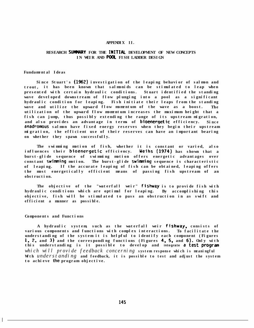
APPENDIX II.
RESEARCH SUMARY FOR THE INITIAL DEVELOPMENT OF NEW CONCEPTSIN WEIR AND POOC FISH LADDER DESIGN
Fundamental Ideas
Since Stuart's (1962) investigation of the leaping behavior of salmon andtrout, it has been known that salmonids can be stimulated to leap whenpresented with certain hydraulic conditions. Stuart identified the standingwave developed downstream of flow plunging into a pool as a significanthydraulic condition for leaping.wave and utilize the upward
Fish initiate their leaps from the standingflow momentum of the wave as a boost. The
utilization of the upward flow momentum increases the maximum height that afish can jump, thus possibly extending the range of its upstream migration,and also provides an advantage in terms of bioenergetic efficiency. Sinceanadromous salmon have fixed energy reserves when they begin their upstreammigration, the efficient use of their reserves can have an important bearingon whether they spawn successfully.
The swimming motion of fish, whether it is constant or varied, alsoinfluences their bioenergetic efficiency. Weihs (1974) has shown that aburst-glide sequence of swimming motion offers energetic advantages overconstant swimming motion.of leaping.
The burst-glide swimming sequence is characteristicIf the accurate leaping of fish can be obtained, leaping offers
the most energetically efficient means of passing fish upstream of anobstruction.
The objective of the "waterfall weir" fishway is to provide fish withhydraulic conditions which are optimal for leaping. By accomplishing thisobjective, fish will be stimulated to pass an obstruction in as swift andefficient a manner as possible.
Components and Functions
A hydraulic system, such as the waterfall weir fishway, consists ofvarious components and functions with complex interactions. To facilitate theunderstanding of the system it is helpful to identify each component (Figures1, 2, and 3) and the corresponding functions (Figures 4, 5, and 6). Only withthis understanding is it possible to develop and integrate a test program
which will provide feedback concerning system response which is meaningfulWith understanding and feedback, it is possible to test and adjust the systemto achieve the program objective.
145

Some pertinent definitions follow:
(1)
(2)
(3)
(4)
(5)
(6)
Waterfall Weir: Routes the flow through the fishway and concentrates theflow momentum prior to the plunge into the downstream pool. Produces astable standing wave over a range of flows. Also serves as an accessopening to upstream pools for leaping fish.
Overflow Weir: Extends the range of flows over which the fishway canfunction. From the model studies it is also apparent that the overflowaids with energy dissipation and may enhance the standing wave.
Fishway Chamber: Provides water storage capacity and constitutes thebase structure of the fishway. The tank geometry influences thehydraulic conditions developed within the pools of the fishway.
Baffling: Dissipates hydraulic energy, directs flow, and guides fish.Influences the overall hydraulics within the pools of the fishway.Contains turbulence upstream of the baffles in each pool.
Downstream Fishway Portal: Attracts fish to the entrance structure andprovides access into the fishway. Serves as the hydraulic exit.
Upstream Fishway Portal: Regulates flow into the fishway and serves asan exit for fish.
Sumnary of Test Programs and Significant ResultsHalf-Scale Modelheir Optimization Study
The purpose of the weir optimization study was to determine the weirshape and orientation angle with the flow that produced the "best* water jetfor use in the fishway. Functional considerations included concentration offlow momentum and development of a stable standing wave in the downstreamplunge pool.
Four weir shapes were tested: 1) hexagonal with one-on-one side slopes,2) semicircular, 3) trapezoidal with four-on-one side slopes, and 4)triangular with a 68-degree, V-notch (Figures 7, 8, 9, and 10). Each weirshape was tested at five orientation angles with the flow (rotated about theupstream edge of the weir from the horizontal position). These were 1) 18degrees, 2) 33 degrees, 3) 45 degrees, 4) 90 degrees, and 5) 135 degrees.Each combination of shape and orientation angle was tested over a range ofdischarges (0.1-2.0 cfs) and tailwater depths (8-40 inches).
The study identified the semicircular shape oriented at 45 degrees as thebest combination. This combination produced the most circular jet, which wasthe criteria for concentration of flow mOmenturn, and the most stable (heightand location) standing wave.
146

A WSE
HWE p1
n SWH vt -
TWE
c
+x*
S/do View
/WATERFALL WEIR
WATERFALLFront View WEIR
Notatlon: CHAMBER
HWE = Hesdwuter elevetlon~TWE = Tallwater e/ever/on:
AWSE = Charge In wafer surface clevetlon:P - D/stance from upsrream tank floor ro we/r crest;
HWW = Hesd on wsterfaft wefr:HOW = Heed on overflow weir;SWH = Stwndfng wuwe hefght;
X - Dfstence t o stundfng wuve f r o m wefr bulkheed.
Figure l--Waterfall Weir Chamber and Nomenclature
147

FLOW
DOF~;‘;~~“\
PORTAL
PLAN VIEW
Figure Z--Schematic of Fishway Entrance Chamber
UPSTREAYFmv~LY \
.
FLOW
PLAN VIEW
/
FlSH WA Y PORTAL
wA ~ERFALL
END VIEW
FISHWAY PORTAL
/ /WA%i%ALL
END VIEW
Figure 3--Schematic of Fishway Exit Chamber
148

STIMULATE FISH TO LEAPF R O M P O O L T O P O O L
PROVIDE. FLOW OVER WEIRWITH CHARACTERISTICS
PROVIDE POOL
WHICH s&lMJ;L$.E FISHCONDITIONS
W H I C H S T I M U L A T EFISH TO JUMP
T O ;;t;DING
-battles
I -battles-tank geometry
CONCENTRATEFLOW MOMENTUM
4-waterfall weir
I
GENERATESTANDING W A V E
ATTRACT FISH I
Figure 4--Subfunction Analysis for Weir Chamber of Fish Ladder
STIMULATE FISH TO ENTERTHE FISHLADDER
tPROVIDE “F[oRwACl
Figure 5--Subfunction Ana
ON LOCATE ENTRANCE WHEREFISH WILL DETECT THE
ATTRACTION FLOW .
ysis for Entrance Chamber of Fish Ladder
REGULATE FLOWI N FISHLADDER
cSIZE OPENING CORRECTLY WASTE EXCESS FLOW
Figure 6--Subfunction Analysis for Exit Chamber of Fish Ladder
149
I
I


Additional testing indicated that the incorporation of sidewalls androunded entrances to the weir further improved the jet shape and stability.These tests were completed early in year 2. (See Project Report Part 2 of 4,Aaserude and Orsborn, 1985).
Full-Scale Model/Energy Dissipation Study
The purpose of the energy dissipation study is to identify thecombination of weir and baffling layout which provides the "best" hydraulicconditions for leapinq. The essence of this study is the development of thefinal design for use in prototype fishwayr. Functional considerations includeenergy dissipation, flow direction, fish guidance, and standing wave formationand stabilization. A more detailed description of the test has been preparedby Aaserude (1983) and Aaserude and Orsborn (1985).
The qualitative phase of the energy dissipation study has been completedwith the result that much has been learned about the response of the system tovarious baffling and weir layouts. The study proceeded with a trial and errorapproach to develop the best waterfall weir. This portion of the study wasconcurrent with the systematic approach taken to identify the best waterfallweir in the weir optimization study. The results highlighted the importanceof sidewalls and rounded entrances to the development of a circular jet (Fig.11). Without sidewalls the jet shape was elongated. To reduce thefluctuations in the location of the standing wave (Fig. 12), an ogee-shapecrest was added to the weir to direct the jet along the same plunge path forvarying discharges. This effectively helped stabilize the location of thestanding wave and could be useful in the final weir design. Because ofproblems with the integrity of the construction of the weir, the seeminglyless than adequate opening for leaping fish and the undesirable jet shape(horseshoe shaped--not circular) produced, the weir was abandoned. It wasdecided to replace it with the semicircular shape identified in the weiroptimization study (Fig. 13).
A rectangular overflow weir layout was studied concurrently with thewaterfall weir development. As anticipated, this is a viable way to extendthe operational range of discharge through the fishway without adverselyaffecting the pool hydraulics. After observing the model, it became apparentthat the sheetflow characteristic of the overflow could provide some hydraulicbenefit. By shearing countercurrents as the sheetflow plunges vertically intothe receiving pool, water pile-up and vorticies in the upstream corners of thepool are attenuated and hydraulic energy is dissipated. When the overflowweirs are positioned such that the sheetflow plunges adjacen't to the weirbulkhead, the circulation pattern promoted may enhance the standing wave.These qualities were analyzed in the quantitative phase of the study early inyear 2.
151


Without baffles,areas of upwelling flow,
a three-foot overfall (US) caused vorticies, scatteredand a generally turbulent appearance throughout the
upstream two-third of the receiving pool. Turbulent hydraulic activity wasparticularly vigorous along the tank boundaries as evidenced by viewing airbubbles entrained in the flow.with the desired flow path for fish
To prevent the boundary jets from competingattraction, a baffle pattern was designed
which shut off the boundary flow and passed incrementally larger volumes offlow per unit area towards the upper center of the pool (Figs. 14 and 15).When oriented at 45 degrees from the tank sidewalls in the upstream direction,and attached at points such that the plane of the baffle aligns with the farside of the weir (Fig. 16), this baffle eliminated most of the vorticies andupwelling and stabilized the standing wave. As anticipated, the areadownstream of the baffles is suitable resting area for fish. The flow moveswell, has simple direct flow lines, and has the appearance of "green water."Much of the air entrained by the jet had been caught and vented to the surfaceby the baffles. The overall performance of the baffle was encouraging. Inthe succeeding phase of the study the effectiveness of various bafflingschemes were quantified.
Following the installation of the semicircular weir that was identifiedas the best in the weir optimization study, it became apparent that the jetshape was dependent on the orientation of the sidewalls. Testing revealedthat both the skew and the lean of the sidewalls significantly affected thejet shape.becomes.
The less skew and lean, the more laterally expanded the jet shapePreliminary results were that a 5-degree skew and a lo-degree lean
produced the most circular jet. Subsequent testing underscored the influenceof discharge on jet shape. Higher discharges tend to expand the cross-sectional jet shape longitudinally. A more thorough analysis of sidewallorientation versus discharge which considers the tradeoffs between the two hasbeen completed. The study identified a workable sidewall orientation for theoperational flow range of the fishway early in year 2.
thereIn addition to the hydraulic benefits of the semicircular weir shape,are two others. One is the 32-inch weir opening. It is anticipated
that leaping fish will be sufficiently accurate to hit this opening with ahigh percentage of success. This opening is eight inches wider than theminimum opening size recommended by Stuart (1962). Tests on leaping accuracywill be conducted this fall. Another benefit is that the simplicity of theweir form lends itself to ease of fabrication. The three-dimensional ogee-crested weir that was developed earlier was not easy to fabricate.
Survey, Interviews, and Literature
The results from the survey, interviews, and literature review providedvaluable information that was used in the development of criteria forinclusion in our test programs (Aaserude, 1983). This research alsohighlighted the need for additional testing by identifying gaps in theunderstanding of fish capabilities, fish behavior, and fishway performance.
154

SlOE ATTACHED
TO CHANBPR WALL
0 000OOO 0@O00000 00ooooo00000
oo”oo
~go”000 00000g 000000 000G0000000000
Figure 15--Baffle pattern designed to shut off the boundary flow and passincrementally larger volumes of flow per unit area towards theupper center of the pool.
AREA WHERE JETENTERS POOL
STANDING WAVE
WEIR CHAMBER
WEIR
155
/ B A F F L E
Figure 16--Plan viewshowing baffleorientation.

The result has been an expanded testing proqram for year 2 with studiesdesigned to resolve: 1) whether fish can be stimulated to jump, 2) thethreshold flow momentum required to stimulate fish to move or leap, 3) fishpreference for weirs, slots, or orifices (i.e., testing of the differentialflow momentum theory), and 4) the accuracy of leaping fish. Below is asumnary of the significant findings resulting from this outside-contact phaseof the project, some with application to the new weir-pool-baffle fishway.
Stmary
1. In some regions, including Scotland and Nova Scotia, and Canada, weir andpool fishways are preferred. In other areas vertical slot, or weir andorifice types are preferred. Preference seems to be based on traditionand the experience of the designer.
2. Weir and pool fishways have been designed with drops between pools aslarge as 2.5 feet. With such a drop, fish pass by swining over the weir(Sedgwick, 1983).
3. At natural falls, fish initiate their leaps from the standing wave formedin the plunge pool.
4. A weir and pool fishway in Scotland uses a rounded weir notch similar tothe semicircular weir shape identified in the weir optimization study.This fishway operates successfully with a discharge of 5-6 cubic feet persecond (cfs) (Sedgwick, 1983).
5. Much of the disagreement between researchers regarding fish capabilitiesand behavior can be attributed to the natural variation of the differentfish stocks studied and unaccounted for hydraulic conditions at theobservation site.
6. The stimulus, fluid, and body mechanics of fish leaping behavior is poorlyunderstood.
7. A weir and pool fishway which utilizes energy dissipation baffles and isdesigned specifically to promote leaping is a new concept in fishwaydesign.
To convey the flavor of this realm of research, several quotes have beenselected:
1. *Jumping still may occur as the phenomenon is not fully understood,although it is known to be triggered by shadow patterns or upwelling,"(Bell, 1973, 1984).
I 156

2. "Salmon will always avoid having to leap to ascend an obstruction if theycan possibly do so, but they frequently indulge in random leaps both atthe foot of falls and in pools for no apparent reason," (Sedgwick,1983).
3. "Salmonids do not jump waterfalls as a last resort but do so with purposeand with a certain calculation." (Bakke, 1983).
4. "... the standing wave forming the departure point. It was no accidentthat these fish, and many others like them, followed an identical route.They picked a common watery pathway enabling them to take full advantageof the hydraulics of the currents and turbulence below the falls--a pathculminating in the spectacular jumps." (Webster, 1965).
5. "All leaps in the laboratory and in the field were observed to beinitiated at the surface of the pool (on the neutral point of the standingwave) . . .'I (Stuart, 1962).
6. "Sensing that the conditions are right to permit their escapement. Thatis, the proper water velocity (or quantity) to permit their successfulnavigation over the obstacle," (Evensen, 1983).
7. "The overfall type has the advantage of being attractive to the fish,"(McLeod and Nemenyi, 1940).
From our research, it is apparent that we are on the right track. Thishas been a constant source of encouragement. The studies completed for Year2 provided valuable information for refinement of the waterfall weir fishway.
General Structural Considerations
To insure that a structure is appropriate for more than a specificapplication it must be developed with consideration for the range of expectedsite conditions. For a fishway, these include remote sitesfield conditions as well as the controlled environment of a damthe lack of control, applications at remote sites are moreshould be considered the worst case for design. If remoteaccommodated, applications at dams should prove easy.
with variableBecause of
difficult andsites can be
To develop a fishway structure for widespread applicat i on at remotesites, versatility and economics must be at the forefront of thought.Versatility is required so that the structure can be fitted to variabletopography. Minimizing the cost of the structure is important so that agreater number of sites can be justified economically for its application.For the waterfall weir fishway, modular construction satisfies both of thesecriteria.
157

The advantages of modular construction are many: 1) it allows thefishway to be designed using standard components of known hydraulicperformance, 2) components can be prefabricated and flown into remote sites,3) components can be assembled on site with a minimun of time and manpower, 4)off-site fabrication provides versatility in material selection (e.g.,fiberglass, aluminum, steel), 5) components can be easily repaired or replaced(e.g., welded, patched), 6) a minimum of foundation preparation is required,and 7) components can be designed to be assembled in versatile configurations(Fig. 17). The net effect is adaptability to variable site conditions andminimal engineering, construction, and maintenance costs. -Resource managerswill be able to mitigate more obstructions to the migration of anadromous fishthan before for the same capital investment.
Final Weir and Pool Design
The final weir and pool fishladder design was developed from thepreliminary laboratory work described in this appendix coupled with the fieldwork at ,Johns Creek hatchery (Aaserude and Orsborn, 1985). The final designis summarized in Fig. 18, and is discussed in more detail in Report Number 1of 4 for this project series (Orsborn, 1985).
158
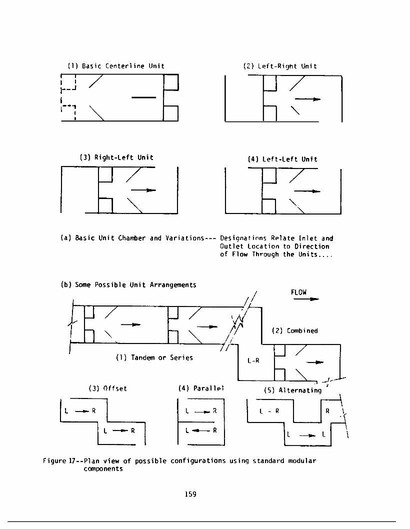
(I) Basic Centerline Unit
I 1
;A
I--' 1
I
(3) Right-Left Unit
(2) Left-Right Unit
\
(a) Basic Unit Chamber and Variations--- Designatinns Relate Inlet andOutlet location to Directionof Flow Through the Units....
(b) Some Possible Unit Arrangements(b) Some Possible Unit Arrangements
IFL01FL01
/ /
(2) Combined(2) Combined
(1)(1) Tandem or SeriesTandem or Series
(3) Offset(3) Offset (4) Parallel(4) Parallel
Figure17--Plan view of possible configurations using standard modularcomponents
159

REFERENCES FOR APPENDIX II
Aaserude, R.G., "Waterfall Weir Energy Dissipation Study--Summary Report,"unpublished paper in Quarterly Progress Report for December, 1982-February, 1983, BPA Project DE-AI79-82BP36526, Fishladder Development,Albrook Hydraulics Laboratory, Washington State University (1983).
Aaserude, R.G. and J.F. Orsborn, "New Concepts in Fishladder Design," Part 2of 4 of a BPA Fisheries Project, No. 82-14, Department of New Concepts inFishladder Design, August 1985.
Bakke, Bill M., Director, Trout and Salmon Resource Center, Portland, Oregon,letter dated May 25, to Dr. John F. Orsborn and Dr. Walter Mih,Department of Civil and Environmental Engineering, Washington StateUniversity, Pullman, Washington (1983).
Bell, Milo C.,Criteria,"
"Fisheries Handbook of Engineering Requirements and Biological
(1973).Fish. Engr. Res. Prog., Corps of Engineers, Portland, Oregon,
Evensen, John C.,dated April
Past President of Steelhead Trout Club of Washinqton, letter9 to Dr.John F. Orsborn and Dr. Walter C.Mih, Department of
Civil and Environmental Engineering,Pullman, Washington (1983).
Washington State University,
McLeod, A.M. and Paul Nemenyi, "An Investigation of Fishways," University ofIowa Studies in Engineering, Bulletin 24, 63 p. (1940).
Sedqwick, S. Drumnond, Consultant to the Scotland Hydroelectric Board, letterdated February 16 to John F. Orsborn, P.E., Department of Civil andEnvironmental Engineering,Washington (1983).
Washington State University, Pullman,
Stuart, T.A., "The Leaping Behavior of Salmon and Trout at Falls andObstructions," Department of Agriculture and Fish for Scotland,Freshwater and Salmon Fisheries Research, Her Majesty's StationeryOffice, Edinburgh, No. 28, 46 p, (1962).
Webster, Dwight A., "Leaping Rainbows of the Finger Lakes," InformationLeaflet, N.Y. State Conservation Department,Education, 4 p. (1965).
Division of Conservation
Weihs, D, "Energetic Advantages of Burst Swimming of Fish," Journal ofTheoretical Biology 48, 215-229 (1974).
161