assessment of mechanisms for
TRANSCRIPT

*S
ASSESSMENT OF MECHANISMS FOREARLY WASTE PACKAGE FAILURES
Prepared for
U.S. Nuclear Regulatory CommissionContract NRC-02-02-012
Prepared by
Vijay JainDarius Daruwalla
Center for Nuclear Waste Regulatory Analyses
Carolyn FairbanksU.S. Nuclear Regulatory Commission
Center for Nuclear Waste Regulatory AnalysesSan Antonio, Texas
January 2003

0 0
PREVIOUS REPORTS IN SERIES
Number Name Date IssuedCNWRA 91-004
CNWRA 91-008
CNWRA 92-021
CNWRA 93-003
CNWRA 93-004
CNWRA 93-014
CNWRA 94-010
CNWRA 94-028
A Review of Localized Corrosion of High-LevelNuclear Waste Container Materials-I
Hydrogen Embrittlement of Candidate ContainerMaterials
A Review of Stress Corrosion Cracking of High-LevelNuclear Waste Container Materials-I
Long-Term Stability of High-Level Nuclear WasteContainer Materials: I-Thermal Stability of Alloy 825
Experimental Investigations of Localized Corrosion ofHigh-Level Nuclear Waste Container Materials
A Review of the Potential for Microbially InfluencedCorrosion of High-Level Nuclear Waste Containers
A Review of Degradation Modes of Alternate ContainerDesigns and Materials
Environmental Effects on Stress Corrosion Cracking ofType 316L Stainless Steel and Alloy 825 as High-LevelNuclear Waste Container Materials
April 1991
June 1991
August 1992
February 1993
February 1993
June 1993
April 1994
October 1994
CNWRA 95-010 Experimental Investigations of Failure Processes ofHigh-Level Radioactive Waste Container Materials
May 1995
CNWRA 95-020 Expert-Panel Review of the Integrated WastePackage Experiments Research Project
September 1995
CNWRA 96-004 Thermal Stability and Mechanical Properties ofHigh-Level Radioactive Waste Container Materials:Assessment of Carbon and Low-Alloy Steels
May 1996
CNWRA 97-010
CNWRA 98-004
An Analysis of Galvanic Coupling Effects on thePerformance of High-Level Nuclear Waste ContainerMaterials
Effect of Galvanic Coupling Between Overpack Materialsof High-Level Nuclear Waste Containers-Experimentaland Modeling Results
August 1997
March 1998
ii

3s,
PREVIOUS REPORTS IN SERIES (continued)
NumberCNWRA 98-008
CNWRA 99-003
CNWRA 99-004
CNWRA 2000-06Revision 1
CNWRA 2001-003
CNWRA 2002-01
CNWRA 2002-02
CNWRA 2003-01
CNWRA 2003-02
NameEffects of Environmental Factors on Container Life
Assessment of Performance Issues Related toAlternate Engineered Barrier System Materials andDesign Options
Effects of Environmental Factors on the AqueousCorrosion of High-Level Radioactive WasteContainers-Experimental Results and Models
Assessment of Methodologies to ConfirmContainer Performance Model Predictions
Effect of Environment on the Corrosion ofWaste Package and Drip Shield Materials
Effect of In-Package Chemistry on the Degradationof Vitrified High-Level Radioactive Waste and SpentNuclear Fuel Cladding
Evaluation of Analogs for the Performance Assessmentof High-level Waste Container Materials
Passive Dissolution of Container Materials-Modelingand Experiments
Stress Corrosion Cracking and HydrogenEmbrittlement of Container and Drip Shield Materials
Date IssuedJuly 1998
September 1999
September 1999
January 2001
September 2001
October 2001
March 2002
October 2002
October 2002
iii

3
ABSTRACT
Early failure of some waste packages may lead to an early release of radionuclides. Earlyfailure also provides a mechanism for water ingress into the failed waste packages, which mayincrease the potential for criticality. This review of the U.S. Department of Energy (DOE) report(CRWMS M&O, 2000) indicates that the evaluation of potential failures and early failuremechanisms for waste packages can be based on historical data obtained from componentswith similar operating conditions or built using similar fabrication processes, if an adequateunderstanding of the origin and applicability of such information is available. Factors with thepotential to cause early failures include human error, equipment failure, and timely inspection.These factors could lead to, among other pitfalls, the generation of flaws during manufacturingand welding, improper use of weld material or heat treatment, and contamination that couldresult in early failures. These failure modes could have significant consequences. The DOEshould provide a technical basis to justify the use of surrogate material data in lieu of Alloy 22and incorporate possibility of unknown degradation mechanisms in its model abstractions. Thereview also indicates that most analyses contained in the DOE report require significant revisionand additional analyses, however, the DOE approach to estimating early failure is acceptable.
Reference
CRWMS M&O. "Analysis of Mechanisms for Early Waste Package Failure."ANL-EBS-MD-000023. Rev. 02. Las Vegas, Nevada: CRWMS M&O. 2000.
v

CONTENTS
Section Page
PREVIOUS REPORTS IN SERIES ......................... iiABSTRACT ............................... vFIGURES ................................. ixTABLES ......................... xiACKNOWLEDGMENTS...................................................... xiiiEXECUTIVE SUMMARY ......................... xv
1 INTRODUCTION .1-1
2 REVIEW OF INDUSTRIAL FAILURES AND FAILURE MECHANISMS ... 2-12.1 Failure of Industrial Components .. 2-1
2.1.1 Boilers and Pressure Vessels .2-12.1.2 Nuclear Fuel Rods .2-12.1.3 Underground Storage Tanks .2-32.1.4 Radioactive Cesium Capsules. 2-42.1.5 Dry Storage Casks for Spent Nuclear Fuel .2-52.1.6 Steam Generator Tubes .2-6
2.2 Aircraft Jet Engines Components .. 2-72.3 Nickel-Base Alloys .. 2-72.4 Use of Surrogate Materials .. 2-82.5 Unanticipated Degradation Mechanisms .. 2-9
3 REVIEW OF FACTORS RELEVANT TO INITIAL FAILURES .3-13.1 Human Error Probabilities .. 3-1
3.1.1 DOE Approach .3-13.1.2 CNWRA Review .3-3
3.2 Equipment Failure Rates.. 3-43.2.1 DOE Approach. 3-43.2.2 CNWRA Review. 3-4
3.3 Reliability of Ultrasonic Examination .. 3-53.3.1 DOE Approach .3-53.3.2 CNWRA Review .3-6
4 ASSESSMENT OF MANUFACTURING DEFECTS IN WASTE PACKAGES ... 4-14.1 Weld Flaws .. 4-1
4.1.1 DOE Approach .4-74.1.2 CNWRA Review .4-10
4.2 Base Metal Flaws in Waste Package .. 4-114.2.1 DOE Approach .4-114.2.2 CNWRA Review .4-12
4.3 Improper Material in Alloy 22 Welds .. 4-124.3.1 DOE Approach .4-124.3.2 CNWRA Review .4-13
4.4 Improper Heat Treatment .. 4-134.4.1 DOE Approach .4-134.4.2 CNWRA Review .4-15
vii
CONTENTS (continued)
Section Page
4.5 Contamination ............................ 4-154.5.1 DOE Approach ............... .......................... 4-154.5.2 CNWRA Review .............. .......................... 4-16
4.6 Unidentified Handling Damage ............... .................... 4-164.6.1 DOE Approach ............... .......................... 4-174.6.2 CNWRA Review .............. .......................... 4-17
4.7 Waste Package Having Thermal Output Outside the Expected Range .... 4-184.7.1 DOE Approach ............... .......................... 4-194.7.2 CNWRA Review .............. .......................... 4-20
4.8 Gap in the Drip Shield Over the Waste Package ........ ............. 4-204.8.1 DOE Approach .............. ........................... 4-204.8.2 CNWRA Review .............. .......................... 4-21
4.9 Summary .................................................... 4-21
5 SUMMARY ............ 5-1
6 REFERENCES .......... 6-1
viii

FIGUP.ES
Figure Page
1-1 Diagram Illustrating the Relationship Between Engineered BarrierDegradation and Other Integrated Subissues .............................. 1-2
4-1 Types of Crack-Like Defects (Chapman and Simonen, 1998) ..... ............. 4-24-2 Schematic Representation of Different Types of Crack-Like Defects ..... ........ 4-44-3 Effect of Weld Thickness on Flaw Density Normalized to a Thickness of
25.4 mm [1 in] ....................................................... 4-84-4 Size Distribution for Indicated Frequency of Occurrence for Outer Surface
Breaking Flaws in Waste Package Alloy 22 Shell Welds ...... ................ 4-94-5 Size Distribution for Indicated Frequency of Occurrence for Outer Surface
Breaking Flaws in Waste Package Alloy 22 Lid Weld ........................ 4-9
ix

0 0
TABLES
Table Page
2-1 Estimated Failure Rates Determined from Experience with Boilersand Pressure Vessels .2-2
2-2 Estimated Failure Rates from Experience with Nuclear Fuel Rods .2-32-3 Dry Spent Nuclear Fuel Storage Designs Approved by NRC for
General Use .2-52-4 Information About Cracks in Dry Storage Casks ............... ............. 2-62-5 Corrosion Failure Modes of Boiling Water Reactor and Pressurized
Water Reactor Components Discovered During Operations .2-10
3-1 Selected Human Error Probabilities and Error Factors ....... ................. 3-23-2 Logical Combinations of Human Error Probabilities for Misloading
an Assembly .3-33-3 Selected Component Failure Rates per Hour ............. .................. 3-4
4-1 Observed Weld Flaw Frequencies ....................................... 4-64-2 Causes of Fuel Failures in Pressurized Water Reactors ....... .............. 4-184-3 Summary of the Review Results ........................................ 4-21
xi

* `* Zs-
ACKNOWLEDGMENTS
This report was prepared to document work performed by the Center for Nuclear WasteRegulatory Analyses (CNWRA) for the U.S. Nuclear Regulatory Commission (NRC) underContract No. NRC-02-02-012. The activities reported here were performed on behalf of theNRC Office of Nuclear Material Safety and Safeguards, Division of Waste Management. Thepaper is an independent product of CNWRA and does not necessarily reflect the views or theregulatory position of NRC. The NRC staff views expressed herein are preliminary and do notconstitute a final judgment or determination of the matters addressed or of the acceptability of alicense application for a geologic repository at Yucca Mountain.
The authors thank G.M. Light for his contribution to a preliminary draft of this report and to thefollowing NRC staff for their technical input: M. Mitchell and A. Hiser (Office of Nuclear ReactorRegulation), and D. Jackson, E. Lois, and T. Santos (Office of Regulatory Research).
The authors gratefully acknowledge G. Cragnolino for technical review, B. Sagar forprogrammatic review; and C. Cudd, B. Long, and A. Woods for editorial reviews. Appreciationis due J. Gonzalez for assistance in preparing this report.
QUALITY OF DATA: Sources of data are referenced in each chapter. CNWRA-generated datacontained in this report meet quality assurance requirements described in the CNWRA qualityassurance manual. Data from other sources, however, are freely used. The respective sourcesof non-CNWRA data should be consulted for determining levels of quality assurance.
ANALYSES AND CODES: None used.
xiii
EXECUTIVE SUMMARY
Early failure of some waste packages may lead to an early release of radionuclides. Earlyfailure also provides a mechanism for water ingress into the failed waste packages, which mayincrease the potential for criticality. The U.S. Department of Energy (DOE) report(CRVVMS M&O, 2000) evaluated the types of defects or imperfections that could occur in awaste package and potentially lead to its early failure. The intended use of the DOE report(CRV\/MS M&O, 2000) is to provide information and inputs to the DOE Total SystemPerformance Assessment. In the report, DOE identified the types of defects applicable to wastepackages, estimated the probability of their occurrence and provided a general discussion of thepotential affect on the long-term performance of the waste package if a defect is present. Thisliterature review, including the review of the DOE report, indicates that the evaluation of thepotential failures and failure mechanisms for waste packages can be based on historical dataobtained from components with similar operating conditions or built using similar fabricationprocesses, if an adequate understanding of the origin and applicability of the existinginformation is available.
Chapter 2 provides a review of studies conducted to estimate failure probabilities of industrialcomponents such as boiler and pressure vessels, spent nuclear fuel rods, underground storagetanks, radioactive cesium capsules, dry storage casks, and steam generator tubes. Alsoincluded in the review are a high-consequence, low-probability event from the aerospaceindustry and the use of nickel-base alloys in the chemical process industry, marine components,and flue-gas desulfurization plants. A discussion is provided about the use of surrogatematerials and the need for an analysis of future degradation mechanisms based on the nuclearreactor experience. However, DOE has not developed an adequate technical basis to justify theuse of surrogate material data in lieu of Alloy 22, and incorporated possibility of unknowndegradation mechanisms in its model abstraction.
Chapter 3 provides a review of key factors used in the assessment of initial failures, andrelevant parameters are discussed. These parameters include human error probabilities,equipment failure rates, and reliability parameters associated with inspections. The DOE reportalso provided insight into the types of failures that led to breakdowns in these components. Toachieve a lower failure rate, careful control and analysis of these failure mechanisms arerequired. A review of the DOE report indicates the human error probabilities are in errorbecause of incorrect use of data in NUREG/CR-1278 (Swain and Guttmann, 1983). DOE useddata that were provided only as examples. This method of determining human errorprobabilities is not acceptable. The systematic methodology described in NUREG/CR-1278(Swain and Guttmann, 1983) should be followed. Also, equipment failure rates must address allequipment to be used in the waste package fabrication process, and additional informationregarding the ultrasonic technique is needed to adequately assess the reliability ofthe inspection.
A review of the accumulated historical data about similar types of containers indicates thatpotential defects arising from the generation of flaws during manufacturing and welding, the useof improper weld materials, improper heat treatments, inadequate weld design, handlingdamage, and potential contamination are important. Chapter 4 provides a review of the DOEinformation and the Center for Nuclear Waste Regulatory Analyses (CNWRA) assessment andanalysis of applicable defects associated with early failures. While the DOE approach toestimating early failures is acceptable, additional analyses should be performed in areas that
xv

could significantly affect the estimated number of early waste package failures. For example,because the welding and heat treatment of the outer lid of the waste package are remoteoperations, it is highly unlikely the sequence of operations used by DOE for developing an eventtree to estimate the probability of improper heat treatment is applicable to outer-lid closurewelds. Also, the DOE report did not provide an event-tree sequence for improper weld material.Either improper weld material or improper heat treatment could result in affecting wastepackage performance. The DOE report lists major assumptions that would affect estimates ofearly waste package failures. Several of these assumptions need to be justified. For example,the assumption that the frequency of occurrence of weld flaws could be based on data collectedusing the expert system-based simulation RR-PRODIGAL code reflects a lack of understandingof the key components of operation and of the sensitivities of the code. Applying the results ofthe RR-PRODIGAL code simulation analysis for nuclear piping published byKhaleel, et al. (1999) to the early failure analysis of Alloy 22 container material requiresadditional technical justification. Furthermore, DOE assumed the simulation results arebounding and conservative by a factor as large as 10 based on the analysis presented bySimonen and Chapman (1999). Simonen and Chapman (1999) based their analysis on themeasurement of weld flaws greater than 4 mm [0.16 in] in depth in pipes and vessels installed inU.S. nuclear power plants and showed that the RR-PRODIGAL code simulations areconservative compared to observed weld flaw frequencies. Analysis provided by DOE,however, ignores the inclusion of the small flaws that could result in a nonconservativeestimate. The CNWRA review of the validation data for the RR-PRODIGAL code (Chapmanand Simonen, 1998) indicates that RR-PRODIGAL code significantly underestimates thenumber of small flaws. The validation data showed that, for the simulation data to match theexperimental data, small cracks less than 3 mm [0.12 in] in size, which account for more than90 percent of the cracks, have to be ignored. Therefore, the DOE assumption results in anonconservative flaw frequency distribution of one to two orders of magnitude. The DOE use ofa simulation scenario with no experimental verification is inappropriate for estimating the flawsize distribution in Alloy 22.
References
Chapman, O.J.V. and F.A. Simonen. NUREG/CR-5505, "RR-PRODIGAL-A Model forEstimating the Probabilities of Defects in Reactor Pressure Vessel Welds." Washington, DC:NRC. October 1998.
CRV\MS M&O. "Analysis of Mechanisms for Early Waste Package Failure."ANL-EBS-MD-000023. Rev. 02. Las Vegas, Nevada: CRWMS M&O. 2000.
Khaleel, M.A., O.J.V. Chapman, D.O. Harris, and F.A. Simonen. "Flaw Size Distribution andFlaw Existence Frequencies in Nuclear Piping." Proceedings of the Probabilistic andEnvironmental Aspects of Fracture and Fatigue: The 1999 ASME Pressure Vessel and PipingConference. PVP-386. New York City, New York: ASME International. pp. 127-144. 1999.
Simonen, F.A. and O.J.V. Chapman. "Measured Versus Predicted Distribution of Flaws inPiping Welds." Proceedings of the Probabilistic and Environmental Aspects of Fracture andFatigue: The 1999 ASME Pressure Vessel and Piping Conference. PVP-386. New York City,New York: ASME International. pp. 101-112. 1999.
xvi

0 0
Swain, A.D. and H.E. Guttmann. NUREG/CR-1278, "Handbook of Human Reliability Analysiswith Emphasis on Nuclear Power Plant Applications: Final Report." Washington, DC: NRC.August 1983.
xvii

I INTRODUCTION
The current waste package design has a corrosion resistant Alloy 22 outer containersurrounding a Type 316 nuclear grade stainless steel inner container providing structuralintegrity (CRVVMS M&O, 2001). A dual lid design is proposed for closure of the outer Alloy 22container. The inner lid will be welded and laser peened to provide compressive stresses in theweld region. The outer lid will be secured with a deep U-groove weld joint with several passesand a cover pass, which is induction annealed to provide compressive stresses in the weldregion. While the U.S. Department of Energy (DOE) is contemplating several changes in thedesign of the waste package that includes use of a flat final closure lid and use of innerlow-plasticity burnishing as a stress mitigation method,' the DOE report about early failures(CRWMS M&O, 2000a) and the review documented in this report do not account for thesechanges. The review is based on a waste package design discussed in Civilian RadioactiveWaste Management System Management and Operating Contractor (CRV\AVIS M&O) 2001.Prior to emplacement in the repository, a remote nondestructive inspection will be performed(CRWMS M&O, 2001).
Early failure of some waste packages may lead to an early release of radionuclides. Earlyfailure also provides a mechanism for water ingress into the failed the waste package, which isessential for the occurrence of criticality (CRWMS M&O, 2001). Early waste package failure isdefined as a failure of a waste package caused by manufacturing or handling induced defects ata time earlier than would be predicted by degradation models for a defect-free waste package(CRWMS M&O, 2000a).
For the undisturbed repository, corrosion is considered the primary degradation process of theengineered barriers (NRC, 2002). Engineered barriers can degrade as a result of disruptiveevents, however, as presented in Figure 1-1. With the exception of igneous activity, DOE hasscreened out all potential disruptive events from consideration of the repository total systemperformance assessment based on either low-probability or low-consequence arguments(NRC, 2002). Center for Nuclear Waste Regulatory Analyses (CNWRA) studies on Alloy 22indicate that breach of a waste package by passive or localized corrosion in the anticipatedrepository environments is highly unlikely within the 10,000-year performance period. In theheat-affected zone around the outer-lid closure weld, however, resistance to localized corrosionmay be reduced significantly leading to early waste package failure. Furthermore, thecombination of residual tensile stresses, defects, and corrosive environment could lead to stresscorrosion cracking of the closure weld.
1cogar, J.A. "Overview of the Design." Presentation at the Nickel Development Workshop #5 on the Fabrication,Welding, and Corrosion of Nickel Alloys and Other Materials for Radioactive Waste Containers October 16-17, 2002.Las Vegas, Nevada. 2002.
2Dunn, D.S., 0. Pensado, C.S. Brossia, G.A. Cragnolino, N. Sridhar, and T.M. Ahn. 'Modeling Corrosion of Alloy 22as a High-Level Radioactive Waste Container Material." Proceedings of the Prediction of Long-Term CorrosionBehavior in Nuclear Waste Systems International Workshop, European Federation of Corrosion Event No. 256,Cadarache, France, November 26-29, 2001. In press. 2002.
1-1

-
( Volcanic Disruption ofWaste Packages
Waste packages already failedby volcanic disruption cannotbe failed again by corrosion
Radionuclide Release Ratesand Solubility Limits
Radionuclides arereleased from
failed waste packages
_ .
Waste packages already failedby corrosion cannot be failedagain by volcanic disruption
Waste packages and drip shielddamaged by rockfall or faulting may
experience enhanced corrosionat the impact site
Engineered BarrierDegradation (Humidity,
Chemistry, andTemperature)
-
i)
Nearby dike intrusion affects near-fieldchemistry (e.g., sulfide concentration
and pH) and temperature
/
Near-field chemistry affectwaste packages and drip
shield corrosion rates
idynot bedisruption
Corrosion products from corrodedwaste packages affect the
near-field chemistry
S
Waste packages and dripshield already failed
by mechanical disruption cannotbe failed again by corrosion
I
VWaste packages
and drip shield alreefailed by corrosion cani
failed again by mechanical
j
H Quantity and Chemistry ofWater Contacting Waste
Packages and Waste FormsMechanical Disruption of
Engineered Barriers(Seismicity. Faulting,
Rockfall, and Dike Infusion)
Figure 1-1. Diagram Illustrating the Relationship Between Engineered Barrier Degradation andOther Integrated Subissues

DOE evaluated the types of defects or imperfections that could occur in a waste package andpotentially lead to its early failure. The intended use of the DOE report is to provide informationand inputs to the DOE Total System Performance Assessment. In the report, DOE identifiedthe types of defects applicable to waste packages, estimated the probability of occurrence andprovided a general discussion of the effect on the long-term performance of the waste packageif the defect is present. In the outer-lid closure weld of a waste package, weld flaws originatefrom defective material, inadequate welding process and technology, improper welding skills forremote welding, and unreliable equipment. This report reviews the DOE methodology forestimating early waste package failures using simulation data from the expert-system basedsimulation RR-PRODIGAL code and event-tree analysis to quantify probabilities of failure forvarious manufacturing defects (CR/MS M&O, 2000a). In addition, this report provides areview of other available information, and an analysis of weld flaws for the outer-lidclosure weld.
1-3

/) 2* 0
2 REVIEW OF INDUSTRIAL FAILURES AND FAILURE MECHANISMS
This section provides a review of studies conducted to estimate failure probabilities of industrialcomponents in the aerospace industry, chemical process industry, marine, and flue-gasdesulfurization facilities. In addition, a discussion is provided about the use of surrogatematerials and the need for incorporating possibilities of unknown future degradationmechanisms based on the nuclear reactor operating experience.
2.1 Failure of Industrial Components
In 1994, the Center for Nuclear Waste Regulatory Analyses (CNWRA) conducted an in-depthreview that focused on field engineering experience with structural materials(Tschoepe, et al., 1994). The summary provided in this section is extracted fromTschoepe, et al. (1994) and the U.S. Department of Energy (DOE) report about initial wastepackage failures (CRWVMS M&O, 2000a). The information presented in this section can beused as a guide for determining the probability of failures for various errors that could occurduring the fabrication and qualification of waste packages. Failure histories of components withsimilar welding and qualification backgrounds are available for boilers and pressure vessels,nuclear fuel rods, underground storage tanks, radioactive cesium capsules, and dry storagecasks for spent nuclear fuel.
2.1.1 Boilers and Pressure Vessels
The construction of boilers and pressure vessels is similar to the construction of wastepackages because they are welded, metallic components of similar thickness typicallyfabricated according to accepted standards and inspected prior to entering into service. Inaddition, there have been several statistically significant studies about the number and types offailures that occurred in a fairly large population. Information about estimated failure rates isprovided in Table 2-1. Boiler and pressure vessel defects, such as weld flaws, base metalflaws, use of improper material in welds, improper heat treatment of welded or cold-workedareas, improper weld flux materials, poor joint design, and contaminants are similar in natureand may be applicable to the waste packages. The failure rate data for boilers and pressurevessels, however, cannot be directly applied to the waste packages because of significantdifferences in operational conditions and the degree of inspection performed prior to service.
2.1.2 Nuclear Fuel Rods
Nuclear fuel rods are conceptually similar to waste packages because they are manufactured inlarge numbers, subjected to rigorous quality control and inspection, and have radionuclidecontainment as one of their primary functions. There are significant differences, however,because nuclear fuel rods (i) are simple, single-barrier components with small wall thicknesses,(ii) have significantly different operating conditions, and (iii) have a much shorter period ofoperation. The failure rate information presented for nuclear fuel rods, therefore, cannot bedirectly used to develop a probability for early waste package failures, but the information canbe used to provide some guidance. It is necessary, however, to establish a distinction betweenoperational failures and failures caused by undetected manufacturing defects. The lowfrequency of fuel rod failures caused by undetected manufacturing defects is attributed100 percent to nondestructive testing. In recent years, most of the fuel rod failures for which the
2-1

0
Table 2-1. Estimated Failure Rates Determined from Experience with Boilers andPressure Vessels
NumberReference of Sample Estimatedof Study Failures Population Comments Failure Rate
Doubt* 229 20,000 Vessels-all welded or forged 8.5 x 10 4 perunfired pressure vessels with vessel yearwall thicknesses greater than9.5 mm [0.37 in] and workingpressure in excess of 724 kPa[105 psi], all less than40 years old. There were17 cases of external leakageor rupture in service identifiedas caused by preexistingdefects in the weld or basemetal or caused by incorrectmaterial. Most failuresoccurred in regions wherenondestructive examinationwas not performed. It isassumed that if nondestructiveexamination was performed, alarge number of the criticaldefects would havebeen detected.
National 6,400 27,000,000 Failures were listed as caused 2.4 x 10⁻⁴ perBoard of by faulty design or fabrication. vessel yearBoiler andPressureVesselInspectorstGerman - BetweenDatabases* 2 x 10⁻⁶ and
8 x 10⁻⁵ pervessel year
*Doubt, G. 'Assessing Reliability and Useful Life of Containers for Disposal of Irradiated Fuel Waste."AECL-8328. Chalk River, Ontario, Canada: Atomic Energy of Canada Limited. 1984.tNational Board of Boiler and Pressure Vessel Inspectors. "Incident Reports." Columbus, Ohio: National Board ofBoiler and Pressure Vessel Inspectors. 1999.qTschoepe, III, E., D.M. Dancer, Jr., C.G. Interrante, and P.K. Nair. "Field Engineering Experience with StructuralMaterials." San Antonio, Texas: CNWRA. 1994.
2-2

/ 3315
failure cause was known have been attributed to operational factors (Tschoepe, et al., 1994).Estimated failure rates for nuclear fuel rods are given in Table 2-2. The failure rate data fornuclear fuel rods cannot be directly applied to waste packages because of significantdifferences in construction and operational conditions. Manufacturing defects, such as weldflaws, base metal flaws, mislocated welds, missing welds, material out-of-specification, handlingdamage, and contaminants, however, also may be encountered in waste packages.
2.1.3 Underground Storage Tanks
Extensive information is available about the causes of early failure for underground storagetanks. The U.S. Environmental Protection Agency (EPA) provided data through 1987 for baresteel, clad or coated steel, and fiberglass reinforced plastic tank systems (EPA, 1987a,b). The
Table 2-2. Estimated Failure Rates from Experience with Nuclear Fuel Rods
Reference of Number of Sample EstimatedStudy Failures Population Comments Failure Rate
Electric Power Not Not Utilities, vendors, and the 3 x 10⁻⁴ toResearch reported reported U.S. Nuclear Regulatory 6 x 10⁵ per rodInstitute* Commission monitor
failure of nuclear fuelrods. A large databaseexists, which providednuclear fuel rod failurerates through 1985 forboth pressurized waterreactors and boiling waterreactors.
YangT Not Not Improvements were made 4.6 x 10⁻⁴ perreported reported in the design and assembly
fabrication to decrease 1.7 x 10⁻⁶ per rodpotential for failure.Failures were caused byhandling damage.
Potts and 47 4,734,412 Failures were caused by 9.9 x 10b6 per rodProestle_ manufacturing defect.Tschoepe, 16 570,200 Failures were caused by Betweenet al.5 manufacturing defect. 1.2 x 10⁻⁵ and
8.2 x 10⁶ perrod
*Electric Power Research Institute. 'The Technical Basis for the Classification of Failed Fuel in the Back End of theFuel Cycle." EPRI TR-108237. Palo Alto, California: Electric Power Research Institute. 1997.tYang, R.L. 'Meeting the Challenge of Managing Nuclear Fuel in a Competitive Environment." Proceedings of the1997 International Topical Meeting on LWR Fuel Performance, Portland, Oregon, March 2-6, 1997. LaGrange Park,Illinois: American Nuclear Society. pp. 3-10. 1997.tPotts, G.A. and R.A. Proestle. "Recent GE BWR Fuel Experience." Proceedings of the 1994 International TopicalMeeting on Light Water Reactor Fuel Performance, West Palm Beach, Florida, April 17-21, 1994. LaGrange Park,Illinois: American Nuclear Society. pp. 87-95. 1994.5Tschoepe, III, E., D.M. Dancer, Jr., C.G. Interrante, and P.K. Nair. "Field Engineering Experience with StructuralMaterials." San Antonio, Texas: CNWRA. 1994.
2-3

0 9
dominant factor in underground storage tank leakage is overfilling and leaking at attachedpiping. A significant number of cases of tank failures also have been reported. Approximately95 percent of the failures have occurred in bare steel tanks as a result of corrosion. Many tanksevaluated in the studies showed through-wall corrosion holes that were plugged by corrosionbyproducts and, consequently, did not leak. Data from EPA suggest an upper bound of0.04 percent of the fraction of the population of underground storage tanks initially failedbecause of unidentified manufacturing defects. The failure rate data for underground storagetanks cannot be directly applied to waste packages because underground storage tanks aresingle shell, less robust, noncorrosion-resistant barriers. Commercial grade quality controls,however, can produce components with a relatively low rate of unidentified defect enteringservice. Various types of manufacturing defects that may be found in waste packages are weldflaws and handling damage.
Historical data show the containers were routinely subjected to varying degrees of inspections.These inspections allow mitigative actions to be taken if unanticipated causes of failure arise.The discussion in the DOE report (CRVMS M&O, 2000a) about the underground storage tanksillustrated the complexities in transferring error rates from one industry to other. Mostunderground storage tanks contained petrochemicals and generally leaked prematurelybecause of failure of the cathodic protection systems. In the mid-1980s, more stringent EPAregulations regarding underground storage tanks were enacted, and as a result, mostunderground storage tank owners replaced steel underground storage tanks with fiberglasstanks. The DOE report states that for one study, "5 to 7 percent of bare steel tanks leakedwhen they were tested for the first time due to manufacturing or installation defects." The DOEreport then concluded that most of these initial defects would be discovered and repaired so thefraction of the population failed by unidentified defects would be much lower, and the reportidentified a different study in which manufacturing defects were closer to 0.0003 percent. Thesedata reflect the need of
* Identifying repair criteria, repair processes, and applicable quality assurance.
* Using only relevant data from industries that operate under differing conditions with differingquality assurance criteria. For example, in some industries, containers may be able totolerate larger manufacturing defects than would be permissible for a waste package and,therefore, may not recognize certain flaws as defects.
* Recognizing that a number of manufacturing defects may reduce with time as wastepackage manufacturing and other waste package handling operations incorporate lessonslearned from startup operations.
2.1.4 Radioactive Cesium Capsules
At the DOE Hanford facility, 1,600 radioactive cesium capsules were fabricated between 1974and 1983 for use as sources by commercial companies (Tschoepe, et al., 1994). There is onlyone known failure partly attributed to storage conditions that were drastically difficult from thosefor which capsules were designed; therefore, the failure rate was 6.3 x 10⁻⁴ per capsule.
2-4
/C/
3 S
2.1.5 Dry Storage Casks for Spent Nuclear Fuel
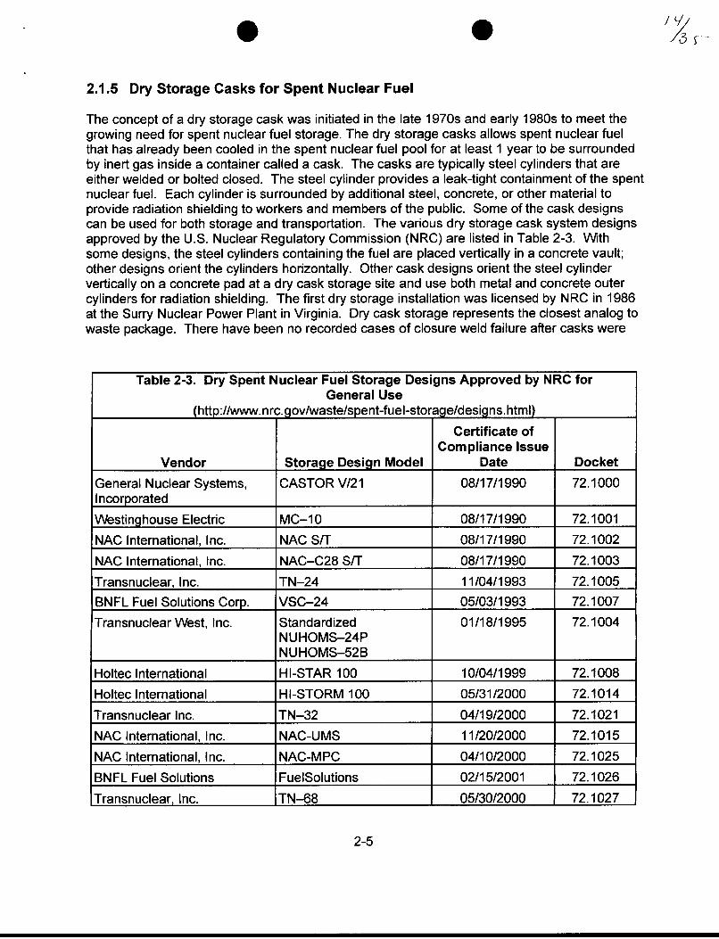
The concept of a dry storage cask was initiated in the late 1970s and early 1980s to meet thegrowing need for spent nuclear fuel storage. The dry storage casks allows spent nuclear fuelthat has already been cooled in the spent nuclear fuel pool for at least 1 year to be surroundedby inert gas inside a container called a cask. The casks are typically steel cylinders that areeither welded or bolted closed. The steel cylinder provides a leak-tight containment of the spentnuclear fuel. Each cylinder is surrounded by additional steel, concrete, or other material toprovide radiation shielding to workers and members of the public. Some of the cask designscan be used for both storage and transportation. The various dry storage cask system designsapproved by the U.S. Nuclear Regulatory Commission (NRC) are listed in Table 2-3. Withsome designs, the steel cylinders containing the fuel are placed vertically in a concrete vault;other designs orient the cylinders horizontally. Other cask designs orient the steel cylindervertically on a concrete pad at a dry cask storage site and use both metal and concrete outercylinders for radiation shielding. The first dry storage installation was licensed by NRC in 1986at the Surry Nuclear Power Plant in Virginia. Dry cask storage represents the closest analog towaste package. There have been no recorded cases of closure weld failure after casks were
Table 2-3. Dry Spent Nuclear Fuel Storage Designs Approved by NRC forGeneral Use
(httD://www. nrc.aov/waste/sDent-fuel-storaae/desians. html)
Certificate ofCompliance Issue
Vendor Storage Design Model Date Docket
General Nuclear Systems, CASTOR V/21 08/17/1990 72.1000Incorporated
Westinghouse Electric MC-10 08/17/1990 72.1001
NAC International, Inc. NAC S/T 08/17/1990 72.1002
NAC International, Inc. NAC-C28 S/T 08/17/1990 72.1003
Transnuclear, Inc. TN-24 11/04/1993 72.1005BNFL Fuel Solutions Corp. VSC-24 05/03/1993 72.1007
Transnuclear West, Inc. Standardized 01/18/1995 72.1004NUHOMS-24PNUHOMS-52B
Holtec International HI-STAR 100 10/04/1999 72.1008
Holtec International HI-STORM 100 05/31/2000 72.1014
Transnuclear Inc. TN-32 04/19/2000 72.1021
NAC International, Inc. NAC-UMS 11/20/2000 72.1015
NAC International, Inc. NAC-MPC 04/10/2000 72.1025
BNFL Fuel Solutions FuelSolutions 02/15/2001 72.1026
Transnuclear, Inc. TN-68 05/30/2000 72.1027
2-5

0 9
placed into service (Hodges, 1998). Four cases have been reported, however, where cracks inthe closure welds were identified during a post-weld inspection of the cask (Hodges, 1998).This information is presented in Table 2-4.
Table 2-4. Information About Cracks in Dry Storage Casks
Location of Failure Description of Crack Cause of CrackShield lid-to-shell Approximately Preexisting condition in the rolling plane ofweld defect 152.4 mm [6 in] long the shell material that was opened by
by 3.2 mm [1/8 in] constructing the shield lid weld. The defectdeep may have resulted from an improper repair
or incomplete removal of temporarylow-quality welds used to facilitate thefabrication process (e.g., an attachmentweld for a strong back used to assist in therolling of plate material)
Structural lid-to-shield Three cracks, each Poor welding technique and moistureweld less than 25.4 mm contamination
[1 in] long, locatedalong the center of theroot pass
2.1.6 Steam Generator Tubes
Steam generator tubes have a number of characteristics in common with waste packages. Bothare and will be produced in large quantities under stringent quality control and surveillanceprograms. Steam generator tubes, however, have much shorter lives, and operating experiencewith steam generator tubes has been very troubling for many pressurized water reactors.'Steam generator tubes degrade with service time because of physical mechanisms such ascorrosion and phosphate wastage, pitting, denting, wear, stress corrosion cracking, andintergranular attack. Industry efforts have been largely successful in managing degradationcaused by wastage and denting, but stress corrosion cracking and intergranular attack remainas more difficult problems. The modes of steam generator tubes have evolved from phosphatewastage in the early 1970s to denting in the late 1970s and stress corrosion cracking in 1980s.The changes in the degradation modes have led to the changes in the inspection technologies.The interpretation of nondestructive examination inspection data, however, is somewhatsubjective and depends strongly on the experience of the analyst. Improvements are needed inflaw sizing capability and in the probability of detecting flaws in areas of high background noise.
While steam generator tubes have significant operational failures caused by knownmechanisms as discussed above, stringent quality control and surveillance have significantlyreduced manufacturing defects. Tschoepe, et al. (1994) cited steam generator tube failure datacollected by the Atomic Energy of Canada Limited in 1981 in which a survey of 1,549,816 tubes
1Chokshi, N.C. "Aging Effects on Plant Safety-Now and in the Future." Presentation to the IAEA TechnicalCommittee Meeting on Maximizing Aging in Nuclear Power Plants June 26-28, 2001. Vienna, Austria. 2001.
2-6

showed defects in 4,692 tubes. Furthermore, only one tube had a defect possibly attributableto manufacturing.
2.2 Aircraft Jet Engine Components
Failure of aircraft jet engine compressor rotors and disks made of titanium alloy is provided inthis section to show importance of minor defects that could result in catastrophic failures. Whilethis is not directly applicable to early waste package failure, it provides an example ofinadequate material performance leading to a high-consequence, low-probability event.
Titanium alloys, formerly processed by double-vacuum arc remelting and now by triple-vacuumarc remelting, are used for fans, compressor rotors and disks in aircraft jet engines. Occasionalupsets during processing can result in the formation of metallurgical anomalies referred to ashard alpha. Although rare, these anomalies have led to engine failures that resulted in fatalconsequences such as the accident in Sioux City, Iowa, in 1989. In 1991, as a result of thisaccident, the Federal Aviation Agency requested that industry review the available techniques todetermine if a damage tolerance approach can be introduced to produce a reduction in the rateof uncontained rotor events. This enhancement was intended to supplement, not replace, thecurrent safe-life design methodology. Southwest Research Institute@, in collaboration with fourmajor gas turbine manufacturers, developed a probabilistically based damage tolerance designcode called Design Assessment of Reliability With Inspection (DARV\WN) to determine the risk offracture of turbine engine rotor disks containing undetected material anomalies caused by hardalpha defects in titanium structures (Office of Aviation Research, 2000). DARVIN integratesfinite element stress analysis results, fracture mechanics based life assessment of low-cyclefatigue, material anomaly data, probability of anomaly detection, and inspection schedules todetermine the probability of rotor disk fracture as a function of applied operating cycles. Theevaluation of anomaly data and probability of anomaly detection were based on 220 millionengine flight cycles in a 6-year reporting period in which 3 titanium melt-related events wereexperienced. A design target risk of 5.0 x 10⁻⁹ events per cycle was selected for engines and1.0 x 10 ' events per cycle was selected for components (Office of Aviation Research, 2000).
2.3 Nickel-Base Alloys
This section provides a brief review of available data on nickel base alloys and identifies theneed for more information on the performance of Alloy 22 waste package material.
CNWRA conducted a review of the industrial experience with nickel-chromium-molybdenumalloys, which can be used as metal analogs for Alloy 22 (Sridhar and Cragnolino, 2002). Thesenickel-base alloys are widely used in marine components, geothermal energy conversionprocesses, the paper and pulp industry, flue-gas desulfurization plants, and waste processingapplications because of their resistance to corrosion. A historical examination of thedevelopment of nickel-base alloys, indicates commercial production and use of these alloysextend to approximately 30 to 75 years if stainless steels are also included. An examination ofthe limited information available about the behavior of these alloys in more severeenvironments, such as those encountered in flue-gas desulfurization systems or the chemicalprocessing industry, provides confidence in the preservation of the passivity of Alloy 22 for wideranges of temperatures, potentials, and concentration of aggressive species, such as chloride,fluoride, and sulfur oxyanions. Probability data about the failure of nickel-based alloycomponents, however, are not available.
2-7

2.4 Use of Surrogate Materials
Providing technical bases for justifying the use of a surrogate material is a complex issue. NRCstaff have been addressing the surrogate materials issue for reactor pressure vessel materialsfor several years. Commercial reactors have ongoing surveillance programs (Strosnider, et al.,1994), in which specimens of the pressure vessel steel used in the reactor are placed insurveillance capsules for testing, after exposure to the reactor core. After samples arewithdrawn from the surveillance capsule, they are analyzed, and correlations are developed todetermine the level of embrittlement in the reactor pressure vessel. The NRC established aregulation that effectively limits the allowable level of pressure vessel embrittlement to protectagainst failure because of pressurized thermal shock events.2 Only very few plants, however,have their limiting materials in their surveillance capsules. For this reason, the issue of crediblesurrogate materials that could be tested in lieu of testing actual limiting materials for a reactorpressure vessel has been and continues to be investigated. The definition of a same materialfor plates and forgings could be a full-thickness section of material removed from the parentbase metal of the same class and heat and given exactly the same post-weld heat treatment.For submerged arc welds, surrogate material could be defined as a full-thickness weldfabricated with exactly the same welding environment and given the same post-weld heattreatment. For example, a section from a vessel drop out or prolongation could be the samematerial if given the same post-weld heat treatment. Anything other than that, some materialsincluding even minor variations in post-weld heat treatment and such, is not considered as thesame material, and it may not qualify as surrogate material. For example, even the abovedescription for same materials requires evaluation because it is well known that one specificlocation in a plate or weld may not give identical properties as those from other locations.The present approach involves determining how well surveillance specimens representmaterials in a vessel as a function of the degree of matching between the importantcharacteristics of the specimen and the vessel materials. As an example, in the case of weldmetals, characteristics may include
* Weld wire* Welding flux* Thickness and weld design* Base metal* Chemical composition* Welding parameters* Simultaneous or separate fabrication* Post-weld heat treatment
Even for the base metal material for reactor pressure vessels, the plant manufacturers havebeen identified as having statistically significant effects on embrittlement behavior. Theproblems associated with surrogate materials demonstrate that addressing the inherent lack ofuniformity between different manufacturers should be discussed since waste packages mayhave different manufacturers.
2Chokshi, N.C. "Aging Effects on Plant Safety-Now and in the Future." Presentation to the IAEA TechnicalCommittee Meeting on Maximizing Aging in Nuclear Power Plants June 26-28, 2001. Vienna, Austria. 2001.
2-8

The history of reactor pressure vessel development demonstrates that wide variations inmaterial properties can exist under narrowly defined material specifications, such as materialswith identical weld wire numbers but having different fluxes, post-weld heat treatment, and such.Considering this experience and the level of significance to the calculation of the waste packagefailure rates, the assumption in the DOE report (CRVVMS M&O, 2000a) that stainless steel datawould be representative or bounding for Alloy 22 requires thorough technical bases forjustification. The effect of the post-weld treatment, such as induction annealing, on the closureweld must be included as well. This could be significant depending on the time lapsed in the900 and 700 0C [1,562 and 1,292 OF] temperature range while cooling from the annealingtemperature {-1,125 'C [-2,057 'F]}. Alloy 22 is highly susceptible to the precipitation oftopologically closed packed phases in this temperature range and, hence, to localized corrosion(Pan, et al., 2002).
2.5 Unanticipated Degradation Mechanisms
It is well documented (Scott, 2000; Staehle, 2000; Marston and Jones, 1992) that the materialsin nuclear power plants exhibit degradation mechanisms with long incubation periods. Somedegradation mechanisms that can cause failure may not be evident at the time of design andmanufacture. One example of such behavior is the experience with piping at nuclear powerplants. In spite of thorough inspections, it has been shown that unanticipated degradationmechanisms were identified, as presented in Table 2-5. The most recent example of initiallyunanticipated degradation mechanism has been the primary water stress corrosion cracking ofreactor vessel head penetration nozzles. NRC efforts to redefine the large break loss-of-coolantaccident will include future unknown degradation mechanisms in its analyses. Another exampleinvolves embrittlement of reactor pressure vessel materials.3 The recently revisedembrittlement trend curve model now includes a long-term, time-effect factor and has addedmanganese and phosphorous chemistries as input. The recent incident at Davis-Besse nuclearpower plant, characterized as degradation of the reactor pressure vessel head, illustrates thesignificant risk associated with the coupling of two corrosion processes that are separately welldefined and investigated such as intergranular stress corrosion cracking of Alloy 600(Scott, 2000) and boric acid corrosion of carbon steel (NRC, 1988). In this case, theintergranular stress corrosion cracking of an Alloy 600 control rod drive mechanism nozzleresulted in leakage of primary water through an axial crack. Boric acid, a component of thepressurized water reactor primary water added as a chemical shim to control reactivity,promoted severe corrosion of the low-alloy pressure vessel steel leaving a deformed portion ofstainless steel clad {0.61 to 0.79 cm [0.24 to 0.31 in] thick} as the only reactor pressureboundary in the 212.9-cm2 [33-in2] corroded area. This last process was not anticipated despitethat the volatility of boric acid is well known, and NRC alerted the utilities in the 1980s aboutboric acid corrosion of carbon steel reactor pressure boundary components. As with the casesinvolving nuclear reactor components, it should not be assumed that all future degradationmechanisms relevant to the waste packages are known at this time. DOE should incorporatesuch unknowns in its uncertainty estimates.
3Chokshi, N.C. "Aging Effects on Plant Safety-Now and in the Future." Presentation to the MAEA TechnicalCommittee Meeting on Maximizing Aging in Nuclear Power Plants June 26-28, 2001. Vienna, Austria. 2001.
2-9

.
Table 2-5. Corrosion Failure Modes of Boiling Water Reactor and Pressurized WaterReactor Components Discovered During Operations
Year of FirstComponent Material Corrosion Failure Mode Occurrence
Boiling water reactor and Zircaloy-2 and Stress corrosion cracking 1973pressurized water reactor Zircaloy-4 (pellet cladding interactioncladding failure)
Boiling water reactor Type 304 SS Intergranular stress 1965recirculation piping corrosion cracking
Secondary side pressurized Alloy 600 Intergranular stress 1970water reactor recirculating corrosion cracking andsteam generator tubing intergranular corrosion
Pressurized water reactor Carbon Accelerated corrosion of 1974recirculating steam generator steel/Alloy 600 support plate or denting oftube support plate/tubing tubing
Primary side pressurized Alloy 600 Intergranular stress 1977water reactor steam corrosion crackinggenerator tubing
Boiling water reactor Various Corrosion fatigue 1970recirculation pump shafts and materialspressurized water reactorcoolant pump shafts
Secondary side pressurized Alloy 600 Pitting 1980water reactor recirculatingsteam generator tubing
Reactor core structural Type 304 SS Irradiation assisted stress 1984components (control rod corrosion crackingguide tubes, core shroud,control blade, and such)
Reactor auxiliary systems Carbon steel Microbially influenced 1984(storage, tanks, spray pond Types 304, corrosionpiping, makeup water tank, 304L, andand such) 316 SS
Pressurized water reactor Carbon steel One- and two-phase 1986feedwater piping and wet flow-assisted corrosionsteam lines (erosion corrosion)
Pressurized water reactor Alloy 600 Intergranular stress 1991vessel head corrosion crackingpenetration nozzles
2-10

0 0 1s
3 REVIEW OF FACTORS RELEVANT TO INITIAL FAILURE
Key factors for assessing initial failures and related parameters are discussed in this section.The parameters include human error probabilities, equipment failure rates, and reliabilityparameters associated with inspections.
3.1 Human Error Probabilities
3.1.1 DOE Approach
Selected human error categories and their probabilities of occurrence based on the handbookby Swain and Guttmann (1983) are presented in Table 3-1. Swain and Guttmann (1983) definehuman error as any member of a set of human actions that exceeds some limit of acceptability.Therefore, an error is an out-of-tolerance action where the limits of tolerable performance aredefined by the system. Errors are regarded as the natural outgrowth of some unfavorablecombination of people and the work situation. Either the person making an error lacks sufficientskill or motivation for consistently acceptable performance or aspects of the work situation arenot in accordance with what can be done reliably, or both. It is important to note that malevolentbehavior is excluded from this definition of human error. Human errors include intentional andunintentional errors. Intentional errors occur when the operator intends to perform some actthat is incorrect but believes it to be the correct act. In everyday language, the operator hasgood intentions, but the effect on the system caused by the performance may be undesirable.Unintentional error is defined as an error that simply happens; it was not intended.
In human reliability analysis, it is important to consider not only the human error but also theconsequence of the human error. Human error probability is defined as the probability thatwhen a given task is performed, an error will occur. There are many ways to estimate thehuman error probability; some are statistical and some are judgmental. The reliability is thengiven by 1-human error probability.
Most human error probability represents best estimates of the human error for the tasks oractivities described. The amount of variation or uncertainty in the estimated human errorprobability is described as an error factor. Uncertainty in the human error probability arises fromthree main sources. The first source is variability in people and conditions. A second source isthe uncertainty in assessing human error probability. The third source is the modelinguncertainty (i.e., How well can the human performance be modeled in a human reliabilityanalysis application?).
The uncertainty is expressed as a lower or upper uncertainty bound-the lower uncertaintybound represents the 5 th percentile of the human error probability, and the upper uncertaintybound represents the 9 5 th percentile on a hypothesized lognormal distribution of human errorprobability for a task. As an example, the expression 0.003 (0.001 to 0.01) means that thenominal human error probability is 0.003. It is believed that the true human error probabilityunlikely would be lower than 0.001 in more that 5 percent of the cases, nor would it be higherthan 0.01 in more than 5 percent of the cases. Most uncertainty bounds are symmetric aboutthe mean, and, therefore, a convenient shorthand term has been defined as an error factor. Inthe previous example, the expression for human error probability could be restated as0.003 (EF = 3). The lower uncertainty bound is calculated by dividing the nominal human error
3-1

Table 3-1. Selected Human Error Probabilities and Error Factors
Report by Swain andHuman Error Guttmann*
Action Probability Error Factor Chapter/PageFailure to follow written 0.010 3 20/22procedure during normalconditionsFailure to use a checklist 0.500 5 20/22properly__ _ _ _ _ _ _ _ _ _ _ _
Error of commission by 0.001 3 20/26reading and recordingquantitative data from anunannunciated digital displayFailure of checker using 0.100 5 20/38written procedures to find anerror made by anothercheckerFailure of operator to detect a 0.010 3 20/30stuck manual valve with nomeans of position indication
Failure to perform rule-based 0.050 10 20/18action correctly when writtenprocedure is available (norecovery factor considered)
Error of commission by 0.001 3 20/28selecting wrong control on apanel from an array ofsimilar-appearing controlsarranged in well-delineatedfunctional groupError of commission by 0.003 3 20/28improperly mating a connector
*Swain, A.D. and H.E. Guttmann. NUREG/CR-1278, 'Handbook of Human Reliability Analysis with Emphasis onNuclear Power Plant Applications Final Report." Washington, DC: NRC. August 1983.
probability by the error factor or 0.003/3 = 0.001. The upper uncertainty bound is calculated bymultiplying the human error probability by the error factor or 0.003 x 3 = 0.009 (for convenience,this can be rounded up to 0.01). The spread between the lower and upper uncertainty boundsin the handbook by Swain and Guttmann (1983) varies according to task conditions.
In general, the spread increases with small (less than 0.001) and large (more than 0.01) humanerror probabilities. Error factors ranging from 3 to 10 are based on judgment and should not beconfused with statistical confidence levels. An example of how to use Table 3-1 for a givenhuman error probability of misloading an assembly into a waste package is provided inTable 3-2. A value of 0.006 was calculated by a combination of errors.
3-2

0 /1<1j
Table 3-2. Logical Combinations of Human Error Probabilities for Misloadingan Assembly
Report by SwainHuman Error Probability and Guttmann*
Action Probability Error Factor of Error Chapter/PageMisloading an assembly 0.05 10 0.005 20/18into a containerdesigned to receive theassembly (operator failsto determine theadequate disposalcontainer designed toreceive the assembly)Selection error 0.001 1 0.001 20/28(operator hasdetermined whichdisposal container touse, but selects thewrong one)Total probability of error _ _ 0.005 + 0.001for misloading an = 0.006assembly
*Swain, A.D. and H.E. Guttmann. NUREG/CR-1278, 'Handbook of Human Reliability Analysis with Emphasis onNuclear Power Plant Applications Final Report." Washington, DC: NRC. August 1983.
3.1.2 CNWRA Review
The treatment of human error was based on NUREG/CR-1278 (Swain and Guttmann, 1983), astandard reference for human reliability analysis. NUREG/CR-1278 provides a methodology forusers to develop human error probabilities and human reliability analyses. NUREG/CR-1278(Swain and Guttmann, 1983) provides basic principles, guidelines, and numerous examples ofhow human behavior and performance are estimated for various situations in nuclear powerplants to assist the user in performing human reliability analyses. To develop human errorprobabilities, the process includes identification of task, analyses, process steps, conditions,underperformance, time for performance, human-machine interfaces, qualifications,dependencies among actions, and performance shaping factors, as well as other inputs. Directreference to selected error categories from the example tables of NUREG/CR-1278 (Swain andGuttmann, 1983) is insufficient for identifying human error probabilities.
Development of human error probabilities for the waste package fabrication process shouldfollow the systematic methodology of NUREG/CR-1278 (Swain and Guttmann, 1983), or thetechnical basis for an alternative methodology must be provided. The waste packagefabrication process is sufficiently analogous to the nuclear power plant situations forNUREG/CR-1278 (Swain and Guttmann, 1983) to be applicable. The methodology ofNUREG/CR-1278 (Swain and Guttmann, 1983) should be applied to specific steps of the waste
3-3

* S
fabrication process and should be described to a sufficient level of detail in the report to allowfor adequate review. A stringent quality control and surveillance programs should be placed toreduce the number of manufacturing defects expected during the startup of thefabrication operations.
In summary, human error probabilities should be calculated utilizing the methodology ofNUREG/CR-1278 (Swain and Guttmann, 1983), and the event trees discussed in theU.S. Department of Energy (DOE) report (CRV\MS M&O, 2000a) should be revised to reflectappropriate human error probability inputs specific to the waste package fabrication process.
3.2 Equipment Failure Rates
3.2.1 DOE Approach
Failures of waste packages can be caused by equipment failures. The DOE report uses failurerates obtained from the Institute of Electrical and Electronics Engineers, Inc. (1984) as listed inTable 3-3.
Table 3-3. Selected Component Failure Rates per Hour
Institute of Electricaland ElectronicsEngineers, Inc.*
Component Low Mean High Page Number
Heater, catastrophic, all 6 x 10-" 1.3 x 10⁻⁶ 2.5 x 10 5 283modes
Thermostat, all modes 1.2 x 10⁻⁶ 5.8 x 10⁻⁶ 1.7 x i0-5 543
*Institute of Electrical and Electronics Engineers, Inc. IEEE Std 500 Reliability Data-IEEE Guide to the Collectionand Presentation of Electrical, Electronic, Sensing Component, and Mechanical Equipment Reliability Data forNuclear-Power Generating Stations. New York City, New York: Institute of Electrical and ElectronicsEngineers, Inc. 1984.
3.2.2 CNWRA Review
DOE selected two specific component failure rates from the Institute of Electrical andElectronics Engineers (1984). All equipment components involved in the waste packagefabrication, however, should have been identified and assessed for predicted failure rates.Justification for excluding any specific equipment component should have been provided. Insummary, insufficient information was provided to evaluate if the specified failure rates areadequate to reflect a systematic assessment of the potential for equipment failure and if the twofailure rates selected reflect a systematic and adequate use of the reference data.
3-4

3.3 Reliability of Ultrasonic Examination
3.3.1 DOE Approach
Because the waste package outer-lid closure weld inspection will have to be performed in a hotcell, the final ultrasonic inspection of the closure weld will also have to be conducted remotely inthe hot cell. Presently, only an ultrasonic inspection of the closure weld is scheduled.Information about the probability that an ultrasonic examination would fail to detect a given sizeflaw was obtained by DOE from Bush (1983) and Heasler and Doctor (1996). This informationrefers to the reliability of ultrasonic testing for detecting various types of weld defects. TheDOE report summarizes the results of previous studies about reliability and providesparameters for a modified log normal function giving the probability of nondetection as afunction of flaw depth as
PND = e + 0.5 x (1-c) x erfc[vxIn(-a-) (3-1)
where
PND - probability of nondetectionC - the lower limit of PND [0.005, based on Bush (1983)]erfc - the complementary error functiona - the flaw depth in centimetersa* - the characteristic flaw depth in centimetersv - a nondimensional shape factor (Bush, 1983)
A more recent study about ultrasonic testing detection of cracks produced by intergranularstress corrosion cracking in stainless steel shows an improved reliability (Heasler and Doctor,1996). The nondetection distribution for a flaw size, a, has the form
PND(a) = 1 - [1 + exp (-A.1 - 82 x a)]- (3-2)
where
)6, = -2.67 (Heasler and Doctor, 1996)fl2 = 16.709 cm-' (Heasler and Doctor, 1996)a = the flaw depth in centimeters
The DOE report (CRV\MS M&O, 2000a) indicates the probability of nondetection for flaws ofvarious sizes is dependent on a number of variables such as the type of material, operator skill,access to the weld, and type of defect. In addition, the flaw size itself can be characterized inseveral ways based on length, depth, or area. Because all these variables could not bespecified, the DOE report used a log normal complementary cumulative distribution functionshowing a 50-percent probability of nondetection for a 2.5-mm [0.1-in] flaw depth and a higherprobability of nondetection for smaller flaws.
3-5
3.3.2 CNWRA Review
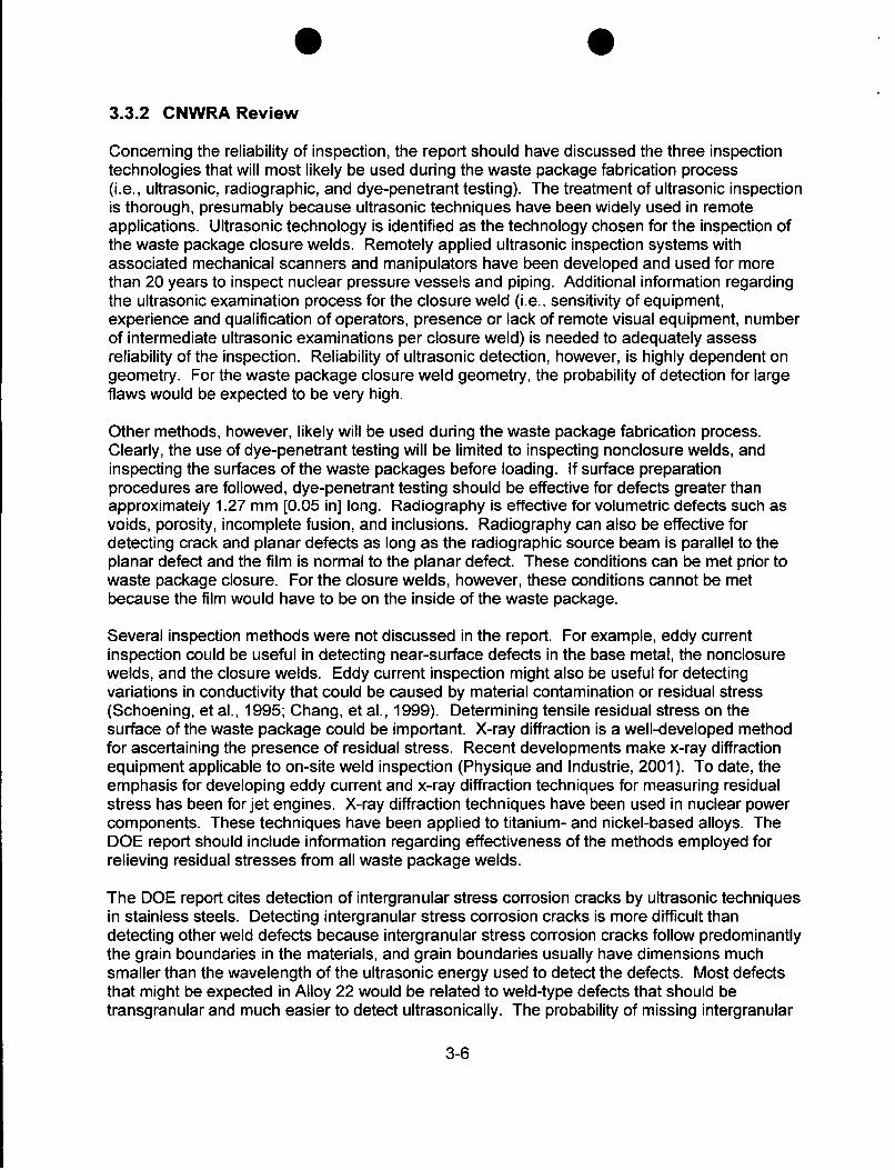
Concerning the reliability of inspection, the report should have discussed the three inspectiontechnologies that will most likely be used during the waste package fabrication process(i.e., ultrasonic, radiographic, and dye-penetrant testing). The treatment of ultrasonic inspectionis thorough, presumably because ultrasonic techniques have been widely used in remoteapplications. Ultrasonic technology is identified as the technology chosen for the inspection ofthe waste package closure welds. Remotely applied ultrasonic inspection systems withassociated mechanical scanners and manipulators have been developed and used for morethan 20 years to inspect nuclear pressure vessels and piping. Additional information regardingthe ultrasonic examination process for the closure weld (i.e., sensitivity of equipment,experience and qualification of operators, presence or lack of remote visual equipment, numberof intermediate ultrasonic examinations per closure weld) is needed to adequately assessreliability of the inspection. Reliability of ultrasonic detection, however, is highly dependent ongeometry. For the waste package closure weld geometry, the probability of detection for largeflaws would be expected to be very high.
Other methods, however, likely will be used during the waste package fabrication process.Clearly, the use of dye-penetrant testing will be limited to inspecting nonclosure welds, andinspecting the surfaces of the waste packages before loading. If surface preparationprocedures are followed, dye-penetrant testing should be effective for defects greater thanapproximately 1.27 mm [0.05 in] long. Radiography is effective for volumetric defects such asvoids, porosity, incomplete fusion, and inclusions. Radiography can also be effective fordetecting crack and planar defects as long as the radiographic source beam is parallel to theplanar defect and the film is normal to the planar defect. These conditions can be met prior towaste package closure. For the closure welds, however, these conditions cannot be metbecause the film would have to be on the inside of the waste package.
Several inspection methods were not discussed in the report. For example, eddy currentinspection could be useful in detecting near-surface defects in the base metal, the nonclosurewelds, and the closure welds. Eddy current inspection might also be useful for detectingvariations in conductivity that could be caused by material contamination or residual stress(Schoening, et al., 1995; Chang, et al., 1999). Determining tensile residual stress on thesurface of the waste package could be important. X-ray diffraction is a well-developed methodfor ascertaining the presence of residual stress. Recent developments make x-ray diffractionequipment applicable to on-site weld inspection (Physique and Industrie, 2001). To date, theemphasis for developing eddy current and x-ray diffraction techniques for measuring residualstress has been for jet engines. X-ray diffraction techniques have been used in nuclear powercomponents. These techniques have been applied to titanium- and nickel-based alloys. TheDOE report should include information regarding effectiveness of the methods employed forrelieving residual stresses from all waste package welds.
The DOE report cites detection of intergranular stress corrosion cracks by ultrasonic techniquesin stainless steels. Detecting intergranular stress corrosion cracks is more difficult thandetecting other weld defects because intergranular stress corrosion cracks follow predominantlythe grain boundaries in the materials, and grain boundaries usually have dimensions muchsmaller than the wavelength of the ultrasonic energy used to detect the defects. Most defectsthat might be expected in Alloy 22 would be related to weld-type defects that should betransgranular and much easier to detect ultrasonically. The probability of missing intergranular
3-6

* *2u~
stress corrosion cracks is higher than the probability of missing a fatigue crack or other weldingdefect. Therefore, the probability of not detecting a fatigue crack or welding defect will beoverestimated by application of Eq. (3-2) which is applicable to intergranular stress corrosioncrack detection.
The DOE report provided information about nondestructive evaluation techniques, initial flawdistributions, and flaw densities for the closure weld only. The DOE report should addressthese issues in detail for nonclosure welds and base metal also.
3-7

* 0S
4 ASSESSMENT OF MANUFACTURING DEFECTS IN WASTE PACKAGES
Civilian Radioactive Waste Management System Management and Operating Contractor[CRWVMS M&O (2001)] identified the following types of defects in its report on initial failures ofwaste packages.
* Weld flaws* Base metal flaws* Use of improper material in welds* Improper heat treatment of welded or cold-worked areas* Improper weld-flux material* Poor joint design* Contaminants* Mislocated welds* Missing welds* Handling/installation damage* Administrative/operational error
The following defects were excluded from further consideration for reasons given.
* Improper weld-flux material has been excluded from further consideration because theU.S. Department of Energy (DOE) will employ a welding method that does not useweld-flux material.
* Poor joint design has been excluded because DOE believes that a significant effort will gointo the design of the final closure joint to ensure that weld designs are acceptable.
* Missing welds are expected in the spent nuclear fuel rods at a rate of 5.0 x 10⁻⁶ per rod.The missing weld in a waste package is easier to identify than in a spent nuclear fuel rod,and it would have a noticeable effect on the configuration of the waste package. Therefore,it is expected the occurrence rate of this defect will be below the threshold probability of 1 Q 8
per waste package (CRWMS M&O, 2000a).
* Mislocated welds is only applicable to very small, single-pass welds. For large multipasswelds, any significant mislocation would cause the weld arc not to strike, which would beevident to the operator and the control system of the automatic welder. Hence, this type ofdefect is not applicable to waste packages.
Review of the DOE information and the Center for Nuclear Waste Regulatory Analyses(CNWRA) assessment and analysis for the applicable defects is provided in the followingsections. It should be noted that the DOE report did not include out-of-specification material asa source of defect in the waste packages.
4.1 Weld Flaws
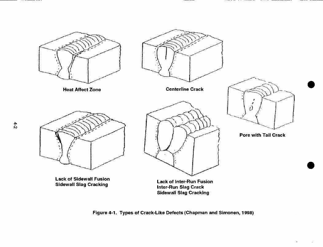
In a welding process, various types of weld flaws, as shown in Figure 4-1, can originatebecause of defective material, inadequate welding process and technology, poor remotewelding skills, unreliable equipment, and poor inspections (Chapman and Simonen, 1998). As
4-1
0Heat Affect Zone Centerline Crack
-1h,
Pore with Tail Crack
Lack of Sidewall FusionSidewall Slag Cracking Lack of Inter-Run Fusion
Inter-Run Slag CrackSidewall Slag Cracking
Figure 4-1. Types of Crack-Like Defects (Chapman and Simonen, 1998)

0 * Ss-
discussed by Chapman and Simonen (1998) and summarized next, these weld flaws can bedescribed as follows. Centerline cracking results from the formation of low strength or lowmelting point phases caused by the collection of impurities at the top of the weld bead duringsolidification. The stresses present on the surface then cause a centerline crack along the weldbead. Automatic high-speed welding techniques, such as submerged arc welding, show agreater tendency to centerline cracking than do manual techniques. The fill runs of largemultipass welds are less susceptible than root welds.
Heat-affected zone cracking is caused by the combination of absorption of hydrogen duringcooling and formation of hardened structure in the heat-affected zone. The risk of heat-affectedzone cracking is higher for the low heat input method and thicker joints because of the low levelof hydrogen diffusivity. There are higher chances of the heat-affected zone cracking in thickerweld joints and in multipass welds. Also, higher restraint may result in a higher number ofheat-affected zone cracks. Heat-affected zone cracking is more likely in high-carbonferritic steels.
Lack of fusion flaws result from lack of union between weld metal and parent plate or betweensuccessive weld runs. Chances of lack of fusion are higher in narrower or deeper weldgrooves. In addition, thicker sections or limited accessibility of electrodes result in a greaterchance of lack of fusion flaws.
Nonmetallic inclusions occur because of incomplete slag removal between weld runs or slaglaminations within the parent plate. Mill scale, rust, or damaged electrode coatings could alsocause formation of such inclusions. Slag inclusions are common in submerged arc welding andmanual metal arc welding, while oxide inclusions are common in tungsten inert gas weldingdeposits. Nonmetallic inclusions are more likely in tighter and thicker weld joints. A thoroughremoval of slag between the runs of a multipass weld reduces the amount ofnonmetallic inclusions.
Porosity is caused by the gas-forming elements present in the welded joint. These gaseousphases evolve as the weld is cooled and form cavities. Porosity is caused by moisture, rust,grease on the plate surface, and oxygen or nitrogen from the atmosphere or shielding gas.Isolated porosity areas could be attributed to an unstable arc. In addition, interdendritic orshrinkage porosity could occur at stop-start positions. Fluxless processes such as tungsteninert gas welding are more susceptible to porosity compared with fluxed processes such assubmerged arc and manual metal arc welding. Also, lack of clean surfaces is a frequent causeof porosity.
Although weld defects are common, and, if detected, they are often mitigated by rewelding,there has been a limited number of research projects focused on the systematic analysis ofdefects in a weld. Available information is limited to studies about size and distribution of weldflaws that were conducted using the RR-PRODIGAL crack simulation code (Chapman andSimonen, 1998) for reactor pressure vessels, and nuclear piping.
The RR-PRODIGAL code is a crack simulation software that reproduces the initiation andinteraction of defects observed in piping and vessels. The software couples Monte Carlosimulations with a knowledge base developed by interactions with welding experts. Figure 4-2shows a schematic drawing of a weld buildup and the positioning of different types of defectspresented in Figure 4-1. A predefined set of distributions is used to select depth and
4-3

A LAYer 6
La er 4
LAW 2
L4We I
LAWerS
Figure 4-2. Schematic Representation of Different Types of Crack-Like Defects (A-HeatAffected Zone Crack, B-Centerline Crack, C-Pore with Tail, D-Lack of SidewallFusion, E-Inter-Run Slag, and G-Sidewall Slag) (Chapman and Simonen, 1998)
dimensions for a defect, and a decision is made if the defect can propagate. If a defect canpropagate, it is taken to the next weld layer. If a second defect initiates within the vicinity of thefirst defect with an overlapping influence zone, the two defects are combined. If a defect fails topropagate, it is assumed to be left behind by the welding process after simulating its depth andlength. Defect width and angle are not simulated. These are, however, used in radiographicand dye-penetrant inspection simulations.
The RR-PRODIGAL code was developed to predict the frequency and distribution of flaws thatoccur during multipass welding for a given type or family of welds. The code modeled welds forsteel piping and vessels of less than 10.16 cm [4 in] in wall thickness and was used by theU.S. Nuclear Regulatory Commission (NRC) licensees for leak-before-break submittals to theNRC. The code was modified in a collaborative program between the Pacific NorthwestNational Laboratory and Rolls-Royce Associates funded by NRC to address vessels with wallthicknesses of 20.32 cm [8 in] or more. The RR-PRODIGAL code has been applied toestimating the probabilities of defects in reactor pressure vessel and in HI-STORM cask welds(Santos, et al., 2001).
A A533B steel pressure vessel research user facility {4.39 m [173 in] in diameter and 13.34 m[525 in] in height) was used for validation of the RR-PRODIGAL code (Doctor, et al., 1999). Thewall thickness of the vessel varied from one region to the other but within 25 cm [10 in] of thebelt line welds, the thickness was 22 cm [8.6 in]. Approximately 2,500 flaws were detectedusing the synthetic aperture focusing technique for ultrasonic testing. Most of the flaws had athrough-wall dimension of greater than 3 mm [0.12 in]. Of 2,500 flaws, 884 were detected in thewelded region that included the heat affected zone. A total weld volume of 0.214 m3 [7.6 ft3]was examined. This gave an average flaw density of 4,131 flaws/m3 [117 flaws/ft3] of weld.This number is significantly higher than weld flaw density obtained by Simonen and Chapman(1999), who conducted a systematic study of welding defects in pipes and vessels installed in
4-4

* 0 f33S
U.S. nuclear power plants. The study found 23 flaws with through-wall depths less than 4 mm[0.16 in]. In examination of 1.9 m3 [67.1 ft3] welds and using the Gumbel distribution, 597 weldflaws {greater than 0 mm [0 in]) were estimated. A flaw density of 314.2 flaws/m3 [8.9 flaws/ft 3]was calculated, which is more than one order of magnitude lower than the experimentallydetermined flaw density in the pressure vessel research user facility vessel. The data weredominated by welds of approximately 2.54 cm [1 in] thickness.
Weld flaws were also examined in the Shoreham reactor pressure vessel (Schuster, et al.,1999). Table 4-1 provides the number of flaws observed in the weld region in the inner andouter 25 mm [0.98 in] depths of the vessel. Ninety-eight percent of the flaws were less than4 mm [0.16 in] in through-wall thickness (Schuster, et al., 1999). These small flaws wereprimarily located in the fusion area slightly {1 mm [0.025 in]) inside the weld. The through-wallextent and the length of small flaws were estimated to be below the resolution of the syntheticaperture focusing technique for ultrasonic testing inspection. The predominant shape wasround, indicating these flaws were less than 3.5 mm [0.138 in] in length.
The observed data for pressure vessel research user facility vessels showed a much largernumber of flaws were smaller in size than predicted by the RR-PRODIGAL code. Although thismay not be a significant concern for structural integrity, small flaws are of interest for estimatinginitial waste package failures. These small flaws can act as initiating sites for stress corrosioncracking. Chapman and Simonen (1998) attribute this inconsistency to
* The RR-PRODIGAL code may systematically underestimate flaw frequencies
* The RR-PRODIGAL code was developed to address only crack-like flaws and excludesvolumetric types of flaws. The inclusion of volumetric flaws would roughly double thepredicted flaw frequencies.
* The RR-PRODIGAL code was developed to predict the expected number of flaws for a largepopulation of vessel welds with given attributes and does not address the differences forindividual welds.
For the flaw depths greater than 5 mm [0.20 in], the observed flaw rates are consistent with theresults predicted by the RR-PRODIGAL code without x-ray examination, while for flaw depths of10 mm [0.39 in], the observed flaw rates are consistent with predicted flaw rates that includex-ray examination. These observations point out serious deficiencies in predicting flaw size anddensities in vessels and warrant us to limit applicability of the RR-PRODIGAL code in thepresence of small flaws.
A selection of pressure vessel research user facility samples were characterized using theradiographic method to determine the shape of the flaws (Schuster, et al., 2000). Results ofradiographic testing confirmed that the fusion surfaces between weld and base metal containedan elevated concentration of flaws and that 30 percent of the flaws were rounded. For largerflaws, however, the rounded flaws were 60 percent.
A comparison of weld flaw data for pressure vessel research user facility and Shoreham vesselindicates the majority (more than 98 percent) of the flaws are small in size {less than 3 mm[0.12 in]), with characterization limited by the resolution of the instrument. A large variability inthe flaw density for small flaws, as shown in Table 4-1, was observed betweenvessels, however.
4-5

Table 4-1. Observed Weld Flaw Frequencies*t
NumberSize of Weld of Flaws/m 3
Vessel Location Cracks Volume Flaws [flaws/ft3]
Pressure Near Surface <3 mm 0.014 m3 191 13,571Vessel Zone {25 mm [< 0.12 in] [0.49 ft3] [384.3]Research User [0.98 in]}Facility
Near Surface >3mm 0.014 m 3 13 929Zone {25 mm [> 0.12 in] [0.49 ft3] [26.3][0.98 in]}
Remaining <5 mm 0.20 m3 653 3,625thickness [< 0.20 in] [0.7 ft3] [102.6]
Remaining > 5 mm 0.20 m3 27 135thickness [> 0.20 in] [0.7 ft3] [3.8]
Shoreham Inner 25 mm <4 mm 0.0226 m3 459 20,309Reactor [0.98 in] surface [< 0.16 in] [0.8 ft3] [574.5]PressureVessel
Inner 25 mm >4mm 0.0226 m3 9 398[0.98 in] surface [> 0.16 in] [0.8 ft3] [11.3]
Outer 25 mm <4 mm 0.0241 m3 639 26,515[0.98 in] surface [< 0.16 in] [0.85 ft3] [750.8]
Outer 25 mm > 4 mm 0.0241 m3 19 788[0.98 in] surface [> 0.16 in] [0.85 ft3] [22.3]
*Doctor, S.R., G.J. Schuster, and F.A. Simonen. NUREG/CP-0166, Vol. 1, "Fabrication Flaws in ReactorPressure Vessels.' Proceedings of the Twenty-Sixth Water Reactor Safety Information Meeting, Bethesda,Maryland, October 26-28, 1998. Washington, DC: NRC. pp. 85-103. June 1999.
Schuster, G.J., S.R. Doctor, S.L. Crawford, and A.F. Pardini. NUREG/CR-6471, Vol. 3, "Characterization ofFlaws in U.S. Reactor Vessels-Density and Distribution of Flaw Indications in Shoreham Vessel."Washington, DC: NRC. November 1999.
4-6
The literature review indicates no studies have been published about Alloy 22, which is thematerial of choice for the waste package outer container.
4.1.1 DOE Approach
To estimate the frequency of weld flaws in the closure weld of the Alloy 22 waste package outerlid, DOE used the results of a simulation scenario used by Khaleel, et al. (1999) as an input tothe RR-PRODIGAL code (CRV\MS M&O, 2000a). As discussed in the previous section, theRR-PRODIGAL code has several limitations including underestimation of small flaws that mayact as initiating sites for stress corrosion cracking. DOE used the following assumptions todevelop the probability of having various size weld flaws in the waste package shell andlid welds.
* Weld flaw density and size distribution information for tungsten-inert-gas welded stainlesssteel can be applied to Alloy 22. The basis for this assumption is that welding Alloy 22 hasbeen identified as a process similar to welding austenitic stainless steel(ASM International, 1993).
* Information on the frequency of occurrence of weld flaws, their locations, and their depthdistributions was obtained from results of the RR-PRODIGAL code.
* Information on the median flaw size and shape parameters for tungsten-inert-gas weldedstainless steel is given as a function of wall thickness {6.35- to 63.5-mm- [0.25- to 2.5-in-]thick welds}.
* Information on density of flaws is based on the simulation scenario that used 25.4-mm-[1-in-] thick stainless steel manual metal arc welds performed in the shop and subjected toinspections by radiographic and dye-penetrant testing.
* All flaws detected by post-weld inspections are perfectly repaired.
* Information on the reliability of radiographic, ultrasonic, and dye-penetrant tests is applicableto the materials and inspection methods that will be used for waste packages.Khaleel, et al. (1999) consider that flaw density increases by a factor of 12.8 for welds withno radiography for stainless steel manual metal arc, and this value is similar for atungsten-inert-gas weld. An increase in flaw density that uses only radiographic and nodye-penetrant test is 31.4.
* Possible defects present in the welds are either rounded and have no direction(e.g., tungsten inclusion, silicon, or porosity) or planar (e.g., lack of fusion). It is assumedthat 1 percent of the defects are planar and in a direction normal to the direction of theweld centerline.
* Flaws are divided into five depth regions: outer surface flaws, flaws within the outer quarterof the weld, embedded center flaws, flaws within the inner quarter of the weld, and innersurface flaws. Based on Khaleel, et al. (1999), and assuming that weld flaws are uniformlydistributed throughout the depth of the weld, it was estimated that 1 percent of the flaws are
4-7

on the inner surface, 11 percent are in the inner quarter of the weld, 49 percent are embeddedin the center, 35 percent are in the outer quarter of the weld, and 4 percent are on theouter surface.
* The probability of a flaw exceeding a depth ranging 1-11.5 mm [0.04-0.45 in] is 1.06 x 10⁹.
* The most likely location for base metal flaws is along the edge of the plate material.
* Embedded flaws are not a concern for postclosure performance, which is based on theassumption that waste packages will not be subjected to cyclic fatigue (the primarymechanism for causing embedded flaws to grow through-wall in similar components).
DOE used the following methodology for estimating the probability of having various size weldflaws in the waste package shell and lid welds.
* The total flaws per type of waste package weld were calculated by multiplying the weldlength by the linear flaw density {given as 0.6839 flaws/m [0.0174 flaws/in] of weld for a25.4-mm- [1-in-] thick stainless steel tungsten-inert-gas weld performed in shop conditions)and by an adjustment factor for weld thickness from Figure 4-3.
* The flaw size distribution was used to determine the probability that a flaw would have a sizewithin a given range.
* The probability of each range was multiplied by the total number of flaws per weld todetermine the expected number of flaws within that size range. For welds subjected toultrasonic inspection, the expected number of flaws within each range was then reduced bymultiplying by the probability of nondetection for the lower end of the size range. Becausethe ultrasonic test probability of nondetection is based on a single-angle ultrasonicexamination, and a multiangle examination is planned for the lid welds, the square of theprobability of nondetection was used for the lid welds.
8 800
7,600 f.it
5 500.0400
. 3.00
0 .00 - -
0 20 40 60 80
Weld Thickness (mm)
Figure 4-3. Effect of Weld Thickness on Flaw Density Normalized to a Thickness of25.4 mm [1 in] (CRWMS M&O, 2000a).
Note: Information Is Presented in mm, use 1 mm = 0.039 in For Equivalent Conversion.
4-8

* For all cases, each range was then multiplied by 0.34 percent (Khaleel, et al., 1999) to yieldthe expected number of outer surface-breaking flaws within that range. On average,0.34 percent of flaws are surface breaking, as shown from Khaleel, et al. (1999).
* Finally, the expected numbers of outer surface-breaking flaws in each size range aresummed to determine a new value for total flaws per weld, which accounts for the ultrasonicinspection. The data for the Alloy 22 shell welds are shown in Figure 4-4 and results for lidwelds in Figure 4-5.
r a>U~.,
CoM C
_ .
- C
i0
IE l01
1.E-02 -_]fi _ _ _ Q _ No tnxpecTn
1E-034 T. and tnul l............ . -T ,nspocon
l , 0 If---I.E- . _ _ _
IE: .__IG _O . r_1.I-07 ! \l
1.1508 __ Ii I'x>1 AL
1E-10g - | l + .1.E-11 .L { 1 ........ _ Li
0 1 2 3 4 5 6 7 8 9 10 11 12 13 14 1s 16 17 18 19 20
Flow Depth (mm)
Figure 4-4. Size Distribution for Indicated Frequency of Occurrence for Outer SurfaceBreaking Flaws in Waste Package Alloy 22 Shell Welds (CRWMS M&O, 2000a).
Note: Information Is Presented in mm, use 1 mm = 0.039 in For Equivalent Conversion.
I.E+001AE-01 i -No Inspechon
1E.02 ---- Bottmn Lid (RT, PT, and rnufi-t4Tinspections) and Outer Extended Lid
3 . t rEX3 - ( \ fmult-UT inspecbions)
I.E-07 "
v o t lE-O' \ ,
1 -.E-9 -
E -10 - sI.E-O1, ,i SNi , ti ,i
0 1 2 3 4 5 6 7 8 9 10 11 12 13 1415 16 17 18 192021222324 25Flaw Depth (mmr)
Figure 4-5. Size Distribution for Indicated Frequency of Occurrence for Outer SurfaceBreaking Flaws in Waste Package Alloy 22 Lid Weld (CRWMS M&O, 2000a).
Note: Information Is Presented in mm, use 1 mm = 0.039 in For Equivalent Conversion.
4-9

The consequence of an outer surface-breaking flaw in combination with the presence of anaggressive environment and high (near-yield) residual stress from the weld could potentiallylead to stress corrosion cracking of the Alloy 22 container. Another consequence of surfaceflaws of any size is the potential for growth of these flaws into deeper pits or crevices. This isunlikely, however, in view of the high resistance of materials, such as Alloy 22, to pitting orcrevice corrosion under the expected repository conditions.
4.1.2 CNWRA Review
Section 4.1.1 lists major assumptions that would affect the calculations for estimating thepotential of early failures. Some assumptions are reasonable, however, some are erroneous orpose serious concerns because of their significant potential to affect analysis of the wastepackage failures nonconservatively. These assumptions include
Published stainless steel data using the RR-PRODIGAL code are bounding for predictingfeatures of flaws in the welds for Alloy 22. DOE assumed the simulation results obtained byKhaleel, et al. (1999) are bounding and the results provided by the RR-PRODIGAL code areconservative by a factor as large as 10 (Simonen and Chapman, 1999). Simonen andChapman (1999) based their analysis on the measurement of weld flaws greater than 4 mm[0.16 in] depth in pipes and vessels installed in U.S. nuclear power plants and showed thatthe RR-PRODIGAL code simulations are conservative compared with observed weld flawfrequencies in reactor pressure vessels. However, they completely ignored observed smallflaws as reported by Chapman, et al. (1996), Chapman and Simonen (1998), Doctor, et al.(1999), and Schuster, et al., (2000, 1999, and 1998). Validation data showed that for thesimulation to match the experimental data, small cracks less than 3 mm [0.12 in] in sizehave to be ignored. Therefore, the DOE assumption results in a nonconservative flawfrequency distribution of one to two orders of magnitude. The DOE use of simulation resultswith no verification is inappropriate for estimating the flaw size distribution in Alloy 22.
* Weld flaw density and depth distributions for tungsten-inert-gas welded stainless steel canbe applied to tungsten-inert-gas welded Alloy 22. Despite differences in the flowcharacteristics of Alloy 22 and stainless steel caused by the sluggish flow of Alloy 22, theDOE report assumed that welding of Alloy 22 is similar to the welding process of austeniticstainless steel. Even though DOE has welded Alloy 22, no systematic analysis has beenconducted to show that the observed weld flaw frequencies are similar to austeniticstainless steel.
* Flaws detected by postweld inspections are perfectly repaired. In reality, this is known notto be the case (Chapman and Simonen, 1998). Experience with nuclear materials hasshown that a large flaw may be repaired, but weld repair tends to leave many small flawsinstead, and repairs to flaws can result in flaws greater than the original flaw. The DOEreport does not include any information regarding requirements for repairs, repairprocesses, or criteria for approval of repair completion.
* In the analysis, the DOE report assumed that 1 percent of the defects are planar and in adirection normal to the direction of the weld centerline. In the Uncertainty Analyses andStrategy (Bechtel SAIC Company LLC, 2001), however, DOE has modified this assumptionto state that all flaws are oriented in such a way that they can grow in the radial direction inthe presence of hoop stress. CNWRA agrees with DOE that this revised assumption is
4-10

conservative. The analysis of the HI-STORM cask also assumed that 100 percent of thedefects would be axially oriented (Santos, et al., 2001).
In the analysis, DOE assumed that embedded flaws are of no concern. DOE needs toevaluate if there exists a critical flaw size that can cause a through-wall crack during aseismic event.
The DOE report used frequency of occurrence of weld flaws, their location and depthdistribution obtained from the results of the RR-PRODIGAL code simulations by Khaleel, et al.(1999). No new calculations were performed using the RR-PRODIGAL code. Various errorsby DOE were noted in the assumptions and use of the data calculated from the results of theRR-PRODIGAL code. The paper by Khaleel, et al. (1999) identifies data for piping materialsderived from the original RR-PRODIGAL code. This paper cites only the flaws near the innersurface of a pipe that would affect fatigue crack growth, and does not address embedded flaws.The waste package outer container material, Alloy 22, may have potentially different crackingmechanisms and different probabilities of occurrence than stainless steel. Flaws buried withinthe welds and flaws breaking the outer surface are of concern to waste package performance.In the RR-PRODIGAL code, the heat-affected zone for stainless steel is assigned a zeroprobability for cracking. It is likely that the probability of the heat-affected zone cracking inAlloy 22 is not zero and verification is needed.
Although the probabilities of various defects that may potentially lead to early failures in wastepackage are discussed, there is no discussion on acceptable range of predicted flaw sizes.DOE proposed using the ASME Boiler and Pressure Vessel code as a guide and indicated thatunacceptable weld defects, as defined in the applicable portions of the ASME code, Section III,Division 1, Subsection NB, shall be repaired in accordance with subsection NB(CRVVMS M&O, 2000b). The discussion on weld flaws developed in the report should beextended to include acceptable range of weld flaw size.
4.2 Base Metal Flaws in Waste Package
Base metal flaws could result from improper waste package fabrication processes, in particularfrom weld repairs made to the base metal.
4.2.1 DOE Approach
The following main assumptions were used to develop the probability of having various sizes ofbase metal flaws in the waste package.
* All base metal flaws occur as a result of weld repairs made to the base metal.
* The most likely location for base metal flaws will be along the edge of the plate material.
* Fabrication procedures will restrict the use of welded attachments to base metal that will beremoved prior to completion of the waste package fabrication.
* A quality control check of the fabrication process will be performed and documented toidentify base metal weld repairs not executed according to the fabrication procedure.
4-11

0 0
The flaw distribution for base metal is based on information from Doctor, et al. (1999) obtainedfrom unused reactor pressure vessels. The flaw densities were found to be one order ofmagnitude lower than those for weld metal. If base-metal flaws occur only as a result of weldrepairs in regions near the welds, and those weld repairs are strictly controlled(CRVVMS M&O, 2000b), then base-metal flaws can only occur as a result of failure to follow thefabrication procedure relating to base-metal forming and weld repair. The human errorprobability for failing to follow a written operating procedure is estimated to be 0.01, and theprobability that the quality control check of the fabrication process will fail to find a violation inthe fabrication procedure is estimated to be 0.1. It is further estimated, that there is a nominalflaw density reduction factor of 0.1 for a base-metal flaw compared with weld flaws. Therefore,the frequency of occurrence of base-metal flaws is estimated to have a probability of occurrence10,000 times less than the flaws in the uninspected welds.
Any outer-surface-breaking flaws, in combination with the presence of an aggressiveenvironment and sufficiently high residual stresses, could potentially lead to stress corrosioncracking. Another possible consequence is the growth of surface flaws into deeper pits orcrevices. Alloy 22, however, is highly resistant to pitting corrosion, and therefore, surface flawsare not expected to grow by pitting corrosion, according to the DOE report.
4.2.2 CNWRA Review
Although the number of base metal flaws is expected to be lower when compared with weldflaws, the DOE report does not provide basis for initiating repairs that could result in formationof base-metal flaws. DOE proposed using the ASME Boiler and Pressure Vessel code as aguide and indicated that unacceptable weld defects, as defined in the applicable portions of theASME Code, Section III, Division 1, Subsection NB, shall be repaired in accordance withSubsection NB (CRWMS M&O, 2000b). The discussion on weld flaws developed in the reportshould be extended to include acceptable range of base-metal weld flaw size.
4.3 Improper Material in Alloy 22 Welds
DOE plans to fabricate, weld, and inspect the waste packages in accordance with the portionsof the ASME Boiler and Pressure Vessel code, Section III, Division 1, Subsection NB (Class 1Components) (ASME International, 1995) that will ensure the waste package will perform inaccordance with the design basis. In addition to two closure-lid welds, the Alloy 22 outercontainer of the waste package will undergo five welds during fabrication (two longitudinal andone circumferential for welding the outer barrier, one for welding the support ring, and one forwelding the bottom lid).
4.3.1 DOE Approach
The following two main assumptions were used to develop the probability of improper materialin the waste package Alloy 22 shell or lid welds.
* Field verification of the chemical composition of each weld wire will be performed prior to itsuse in fabricating any weld on the waste package. It is also assumed that such fieldverification will use new instrumentation such as portable x-ray spectroscopy equipment,which is assumed to work perfectly.
4-12
* 0
The Alloy 22 outer container contains approximately 249 kg [550 lb] of weld material(including closure weld).
Inspection of 47 reactor vessels from 1966 to 1978, indicated 29.5 to 158.8 kg [65 to 350 lb] ofweld wire was out of specification of the 1,935,202 kg [4,266,390 lb] of weld wire used.Probability of use of improper weld material ranges from 6.8 x 10⁻⁴ to 3.7 x 10 5 per unit mass ofweld material. DOE used an adjusted mean of 5.0 x 10⁻⁵ per unit mass for this analysis. Inaddition, the DOE report indicates that the Babcock and Wilcox response to NRC Bulletin 78-12concluded that the evolution of shop practices had virtually eliminated the possibility of usingimproper weld material in the fabrication of a reactor vessel. There is still a 1/1,000 probability(probability of improperly checking the digital readout), however, that an operator performingsuch verification would fail to perform the operation correctly. The probability of using improperweld material is estimated to be approximately 5.0 x 10 8 per unit mass of weld material. Usingan assumed 249 kg [550 lb] mass of weld material in the Alloy 22 barrier yields an estimatedprobability of 2.7 x 10⁻⁵ per waste package for improper weld material.
DOE further states that if an improper material is used, it is expected the improper materialwould be another nickel-based alloy for the outer barrier or another stainless steel alloy for thestructural barrier. The DOE report considers that the use of the improper material could affectthe corrosion performance of the barrier.
4.3.2 CNWRA Review
It is not evident from the DOE analysis that the welding material used in the reactor pressurevessels routinely undergo verification prior to welding. If the welding material in reactor vesselsundergo verification similar to the planned verification for waste packages, the DOE analysis isincorrectly multiplying the probability by 0.001 which accounts for an operator performingverification of the digital readout failing to perform the operation correctly. This would increasethe probability of improper material to 2.7 x 10 2 per waste package. It should be noted thatDOE did not develop an event tree to calculate probability of improper material inAlloy 22 welds.
The use of improper material such as stainless steel will result in a waste package susceptibleto both stress corrosion cracking and localized corrosion, and waste package may havesignificant consequences on the repository performance.
4.4 Improper Heat Treatment
Each disposal container will undergo heat treatment after welding to remove residual stresses.However, no heat treatment is planned after the outer-lid closure weld. Note that beforehigh-level waste is placed in a container, the container is called a disposal container. Once acontainer is loaded with high-level waste and welded, the canister is called a waste package.
4.4.1 DOE Approach
The following assumptions on the heat-treatment process were used by DOE to develop anevent-sequence tree to quantify the probability that a waste package is subjected to improperheat treatment.
4-13

* There is only one heat treatment/annealing operator and the furnace is manually controlled(not computer controlled).
* There are written operating procedures for the ramp-up/hold-time phases and the quenchphase for every disposal container component.
* The operator needs to initially match the waste package components to be heat treated withthe appropriate written heat-treatment operating procedure(s) via some type of digitalidentification code.
* If the operator has a mismatch between the components and the procedure, the ramp-upand hold time will be inappropriate for the components subjected to the heat treatment.
* The ramp-up and hold-time operations can be addressed by one procedure (and, hence,modeled with a single human error probability).
* A quality assurance check of the furnace occurs following the ramp-up and hold-timeoperations and can identify an error in implementing the written operating procedure.
* The quality assurance check of the furnace cannot identify a noncatastrophicequipment failure.
* Components are annealed with a quench following the quality assurance check, and thequench is accomplished with nozzles and hoses (not immersion).
* An independent laboratory check can identify failures caused by noncatastrophic equipmentfailures, such as not following the ramp-up and hold-time operating procedures or notfollowing the quench procedures.
* The furnace has two failure modes: (i) catastrophic, which can be immediately detected;and (ii) noncatastrophic, which can only be detected using a laboratory test.
* The annealing time is approximately 24 hours, during which a failure in the furnace couldlead to an improper heat treatment.
Because heat treatment involves human interaction, the probability of improper heat treatmentis evaluated using an event-sequence tree that focuses on human errors. The heat-treatmentprocess involves several decision points and one potential hardware failure mode. The DOEreport determined the probability of placing a waste package repository with improper heattreatment as 2.21 x 10i5.
Although the likelihood of improper heat treatment is small because of the administrative(procedural) controls and multiple checks, the DOE report noted that the consequences ofimproper heat treatment can be significant depending on the error. The inconsistent coolingrate of alloys such as Alloy 22 may result in precipitation of carbides and inter-metallic phases inthe grain boundaries, which make the material more susceptible to a localized attack along thegrain boundaries and, hence, promote stress corrosion cracking.
4-14

* 0
4.4.2 CNWRA Review
The DOE report determined the probability of placing a waste package into operation withimproper heat treatment was 2.21 x 10i5. It should be noted that 95 percent of this probability iscontributed by a sequence in which the furnace suffers a noncatastrophic failure and anindependent laboratory incorrectly determines that the component was subjected to proper heattreatment. Improper heat treatment produces a defect in the metal not identifiable in theprocedural quality assurance check (because this is not a procedure error).
DOE approach for determining the probability for improper heat treatment is acceptable forfabrication of waste packages. This approach not feasible, however, to conduct independentlaboratory check for an outer-lid closure weld because waste package cannot be moved outsidethe remotely operated facility. DOE should develop an event tree for estimating probability ofimproper heat treatment for the outer-lid closure weld. As indicated by DOE, improper heattreatment could result in a waste package susceptible to both stress corrosion cracking andlocalized corrosion, and may have significant consequences on the repository performance.
4.5 Contamination
The waste package will undergo at least nine cleaning steps before emplacement-afterfabrication of each of the five welds (two longitudinal and one circumferential for welding theouter container, one for welding the support ring, and one for welding the bottom lid), after heattreatment, prior to shipping the empty disposal container to the site, prior to loading thehigh-level waste, and prior to emplacement of the waste package in the drift.
4.5.1 DOE Approach
The following main assumptions were used by the DOE to develop an event-sequence treeto quantify the probability of having corrosion-enhancing surface contamination on thewaste package.
* There are different operators for each cleaning occurrence.
* Each cleaning is independent of the other cleanings.
* Procedures exist to prohibit cleaners that could have a corrosion-enhancing effect on thewaste package metal.
* There is a written operating procedure to perform the cleaning process.
* An incorrect cleaning process with proper cleaning agents cannot leave a residue that canhave adverse effects on the metal.
* A check of the cleaning process occurs.
* The probability of contamination just before final cleaning is assumed to be 0.0163 based ondata from the steam generators of Indian Point-3 and nuclear fuel rods.
4-15

* Failure to have proper cleaning agents is estimated as 0.005, based on the expectation thatmislabeling of cleaning supplies is similar to the failure to follow a written procedure(probability of 0.01) and that the stocking person fails to recover by using the wrongchecklist form (probability of 0.5).
* Human error probability to check the post cleaning correctly is approximated as a probabilityto follow a written procedure (probability of 0. 1). A lower limit of 0.02 was used for a morerigorous check.
* Failure of the cleaning process is approximated by a failure to follow a written procedurewith an human error probability of 0.01.
The probability of placing a waste package into service after being subjected tocorrosion-enhancing surface contamination involves various human interactions with thepotential for human errors. The probability of a contaminated waste package is the sum of theprobability of contamination during each cleaning plus the probability of leaving a wastepackage contaminated during the last cleaning. In the first step, an unacceptable consequenceis obtained when the proper cleaning agent is not used, an operator check fails to acknowledgethe use of the wrong material, and the checker review fails to determine that the cleaning wasperformed properly. This calculation step provides a probability of 5.0 x 10⁻⁵ per cleaning or4.5 x 104 per waste package (assuming nine cleanings). In the second step, which is the lastcleaning, an operator receives a contaminated waste package and incorrectly follows the writtenprocedure, and the checker fails to provide a rigorous review. This calculation step provides aprobability of 3.26 x 10⁻⁶. Based on the assumption that the outer container will be subjected tonine cleanings before emplacement, the probability of a waste package with a contaminatedAlloy 22 outer container is approximately 4.5 x 10⁻⁴.
DOE states that the waste package fabrication specifications will restrict the chemicalcompositions of the cleaning materials and solvents. The fabrication process also calls forremoving all contaminants prior to heat treatment and other operations. Human error, however,could cause either the cleaning to be insufficiently performed or not accomplished at all. Thus,the consequence of this error is not expected to be a significant factor in corrosion.
4.5.2 CNWRA Review
In the DOE report, the probability of contamination was obtained by assuming the total numberof cleanings equals 10, however, there are only nine cleanings. This was obtained bymultiplying by nine the probability of contamination during cleaning followed by a final cleaning.In the first event tree, probability should be multiplied by eight. This correction provides anestimated probability of 4.0 x 10 4 per waste package.
DOE has not provided a list of chemicals that will be present at the site that could result in ahuman error. Without the availability of this information, it is not possible to assign a probabilityor estimate consequences for this event.
4.6 Unidentified Handling Damage
Improper handling can occur during transport at the repository. Handling damage is defined asany gouging or denting of a waste package surface, significant enough to affect postclosure
4-16

performance of the Alloy 22 outer container and that might have the potential to go unnoticed.This event does not consider complete penetration of the outer container or malicious damageto the container.
4.6.1 DOE Approach
The following main assumptions were used to develop an event-sequence tree for quantifyingthe probability of a waste package being emplaced with unidentified handling damage.
* Damage is significant enough to cause penetration of the waste package, and the damagewould not go unnoticed.
* The probability that a waste package is significantly gouged or dented during transport orhandling at the repository is equivalent to the rate at which the fuel assembly failuresoccurred because of handling damage, which is 5 x 10⁻⁴.
* At least the outer container will be inspected for handling damage on arrival at therepository, and the waste package will be inspected before final emplacement in the drift.
* If handling damage occurs and is identified, the waste package is either completely repairedor scrapped.
* Human error probability for failure by the operator to realize that the waste package hasbeen damaged is considered as 0.01. Failure of inspection to detect a damaged wastepackage is considered as 0.1.
Because this type of potential damage involves primarily human error, an event-sequence treewas developed that included (i) waste package damage during transportation to the repository,(ii) failure of the operator to realize that the waste package had been damaged duringmovement, and (iii) failure to detect the damage during inspection. Based on this analysis, theprobability of placing a waste package in the emplacement drift with undetected damage to theouter Alloy 22 container is estimated to be 5.5 x 10⁻⁶.
Gouges on the waste package outer surface could provide sites for the start ofcrevice corrosion.
4.6.2 CNWRA Review
The probability of handling damage is estimated to be 5.5 x 10⁻⁶. Ninety-one percent of thisprobability is associated with the sequence in the event tree in which the handling damage to adisposal container goes undetected during inspections on arrival at the repository and prior toemplacement in the drift as a waste package. The probability of handling damage prior toarrival at the repository is estimated to be 5.0 x 10⁻⁴, based on handling damage data for spentnuclear fuel rods for the period 1989-1995. In addition to the 10 failures (of the 21,810assemblies) caused by handling damage, the data in Table 4-2 indicate 226 failures between1989-1995 attributed to defective assemblies which were not inspected after fabrication. Thisnumber results in a probability of failure of 0.01 (i.e., 226/21,810). Because the latter probabilityis considerably larger, the analysis should be expanded to incorporate an additional event-treesequence wherein an uninspected and damaged disposal container arriving from the fabricator
4-17

0
Table 4-2. Causes of Fuel Failures in Pressurized Water Reactors*
Number of Assemblies
1996Failure Cause 1989 1990 1991 1992 1993 1994 1995 (Partial)
Handling Damage - 6 2 - - 1 1 1
Debris 146 11 67 20 13 6 10 1
Baffle jetting - - - - - - -
Grid fretting 14 18 9 33 36 9 33 19
Primary hydriding - 1 - 4 -
Crudding/corrosion - 4 1
Cladding creep collapse - -= 1 -
Other fabrication 1 15 1 5 3 1 15 3
Other hydraulic 1 - -
Inspected/unknown 36 36 13 2
Uninspected 43 58 35 61 14 3 12 1
Totals 204 109 114 123 103 56 89 27
Total discharged 2,196 3,461 2,937 3,302 3,612 2,636 3,666
*Yang, R.L. "Meeting the Challenge of Managing Nuclear Fuel in a Competitive Environment." Proceedings of the1997 International Topical Meeting on LWR Fuel Performance, Portland, Oregon, March 2-6,1997. LaGrange Park,Illinois: American Nuclear Society. pp. 3-10. 1997.
goes undetected during arrival inspections at the repository and prior to emplacement. Theprobability of this new sequence will be two orders of magnitude greater than the currentlyestimated probability and will have a significant effect on the number of early waste packagefailures expected to occur in the repository.
It is not evident from the DOE description that the probability of damage during handling will besimilar to spent nuclear fuel because the disposal container weighs significantly more than thefuel assemblies and, therefore, could have a higher occurrence of damage during regular orremote handling.
4.7 Waste Package Having Thermal Output Outside the Expected Range
According to waste package specifications, the maximum allowable heat output of a wastepackage is 11.8 kW [4.03 x 10⁴ Btu/hrJ per waste package. Currently, maximum heat output of
4-18

~3X
11.53 kW [3.93 x 1 04 Btu/hr] is from waste packages containing 21 assemblies and minimumheat output of 0.52 kW [1.77 x 10³ Btu/hr] is from waste packages containing 24 assemblies ofboiling water reactor fuel (DOE, 2001).
4.7.1 DOE Approach
The assumptions used by DOE to develop an event-sequence tree to quantify the probability ofa waste package containing 21 assemblies of pressurized water reactor fuel having a thermaloutput outside the expected range as a result of a thermal misload were
* It is possible to load a waste package in such a manner that it will be outside the thermaldesign basis of 11.8 kW [4.03 x 10⁴ Btu/hr] using only the population of fuel available in thepool at any given time.
* Waste package thermal misload results from assembly misload.
* A loading diagram is developed for each waste package, and any failure in developing theloading diagram will lead to a misloaded waste package if the failure is not identified by aquality assurance check or independent verification.
* Quality assurance checks are performed for the loading diagram development and for theloaded waste package.
* A thermal verification of a waste package is performed, and the operator will simply read themeasured thermal output from a digital display.
* Any waste package found to be misloaded will be reloaded so it is within the allowablethermal output range.
The probability that a waste package is accidentally loaded with fuel not within its thermaldesign basis was estimated for a 21-pressurized water reactors waste package because thisrepresents the waste package closest to the maximum allowable heat output of 11.8 kW[4.03 x 10⁴ Btu/hr]. There are two types of human errors that the operator might commit whenselecting the waste package, the fuel assemblies to be loaded, or both: conceptual andselection. The conceptual human error represents the intentional selection of a wrong itembased on an erroneous belief that the item is actually correct. The selection human errorrepresents the unintentional selection of the wrong item while trying to collect the correct item.
The probability of misloads may be higher, however, if the current strategy of blending fuel toachieve the desired heat output is used. Again, there are several human steps involved:(i) developing an incorrect written loading diagram that the operator follows, (ii) failing toproperly check the incorrect written loading diagram, (iii) loading the fuel incorrectly, and(iv) failing to match components with the written procedures. The event-sequence treedeveloped in the DOE report showed the probability of storing a waste package with animproper heat load to be 1.2 x 10⁻⁵, per waste package if the thermal output is verified prior todisposal, which can increase to 1.2 x 10⁻² if the thermal output is not verified prior to disposal.This analysis clearly shows that the thermal output of the load should be verified to minimizepotential misleading.
4-19

* 0
In the DOE report it is noted, based on data obtained from the viability assessment repositorydesign, that the outer temperature of the waste packages as a function of time appears to beroughly the same after the first 200 years regardless of the initial thermal output of the wastepackage. Therefore, it is believed that a thermal misload would not significantly alter theperformance of a waste package after closure.
4.7.2 CNWRA Review
Even though after 200 years the temperature of the waste package containing 21 assemblies ofpressurized water reactor spent nuclear fuel rods is not significantly different compared to otherwaste packages, the differential between the waste packages containing 21 assemblies ofpressurized water reactor fuel and 24 assemblies of boiling water reactor fuel before 200 yearsis almost 60 0C [104 'F] (CRWIMS M&O, 2000a). This differential could create a cold trap effectthat may provide a source of moisture to other waste packages in the drift. Most currentinformation taking into account various thermal options should be used in determining the effectof thermal loading.
4.8 Gap in the Drip Shield Over the Waste Package
In the current engineered barrier design, a titanium drip shield will be placed over the wastepackages at the time of repository closure, and this will be accomplished remotely by amobile gantry.
4.8.1 DOE Approach
The assumptions used to develop an event-sequence tree for quantifying the probability ofhaving a gap in the drip shield over the waste package were
* The operator remotely emplaces the drip shield and performs a self check of the work. Theprobability that the operator fails to properly place the drip shield is based on the humanerror probability of 0.003 estimated for improperly mating a connector. Using the maximumerror factor of 3, DOE is using a probability of 0.009 per waste package for misplaceddrip shield.
* A remote self-check by the operator and a quality assurance inspection of the emplaced dripshield are performed and have a human error probability of 0.1.
* Once a gap in the drip shield has been identified, it is perfectly repaired and a new gap isnot introduced anywhere along the length of the drift.
DOE identified two types of emplacement errors that could occur during emplacement of thedrip shields. First, an operator does not place the drip shield segments (their lengths areslightly larger than that of the waste package) so that the neighboring drip shield segmentsproperly overlap. Second, operator self inspection and quality assurance inspection fail to verifythat the drip shield segments were installed properly. An event-sequence tree was developed inthe DOE report to evaluate the human errors involved with this process, and it was determinedthe potential for drip shield emplacement error was 9.0 x 10 5 per waste package.
4-20

0 0 .3'j/3-
An improperly placed drip shield will provide a gap that will allow water to drip directly onto thewaste package. DOE further states that the current waste package degradation model takes nocredit for the drip shield against dripping (CRWMS M&O, 2000c).
4.8.2 CNWRA Review
DOE uses the human error probability of 0.003 for improperly mating a connector with acorrection factor of 3. It is not evident from the discussion if the human error probability of 0.003is applicable for remote operations or if the error factor of 3 is sufficient to account forremote operations.
A drip shield emplacement error will result in additional dripping of water on the waste packagesurface and, depending on other factors, may provide localized corrosion and enhanceradionuclide release.
4.9 Summary
Review of the DOE approach to estimating early failures is acceptable. Most analyses,however, requires significant revision and additional analyses. Table 4-3 provides a summaryof the discussion presented in this chapter.
Table 4-3. Summary of the Review Results. This Table Combines the DOE Data fromCRWMS M&O* and Includes the CNWRA Comments in the Last Column
Probabilityper Waste Possible Consequences forPackage Postclosure Performance
Waste Degraded Pitting or Stress EarlyPackage Alloy 22 Mechanical Crevice Corrosion Water CNWRA
Defect Type Barrier Properties Corrosion Cracking Contact CommentsWeld Flaws Less than Possible Possible - Flaws < 5 mm(outer surface, 10 4for [< 0.20 in] arebreaking only, flaws ignored in theassuming greater than analysis, whichinspections 5 mm accounts forusing [0.2 in] deep greaterradiographic than 90 percentpenetrant, and of the flaws.ultrasonic Data used fortesting) estimating the
number offlaws is notjustified.
4-21

0
Table 4-3. Summary of the Review Results. This Table Combines the DOE Data fromCRWMS M&O* and Includes the CNWRA Comments in the Last Column (continued)
Probabilityper Waste Possible Consequences for PostclosurePackage Performance
Waste Degraded Pitting or Stress EarlyPackage Alloy 22 Mechanical Crevice Corrosion Water CNWRA
Defect Type Barrier Properties Corrosion Cracking Contact CommentsBuried flaw 10 b for Possible A critical flawextends to the 5.5 mm size that cancritical depth [0.22 in] of result in aof 11.5 mm weld through-wall[0.45 in] or corroding crack from abeyond away seismic event
should beevaluated.
Base metal 10 ' times _ Possible Possible _ No technicalflaws less than basis provided
the weld for acceptingflaw rate base metal
flaws resultingfrom weldrepairs.
Improper weld 2.7 x 10 5 Possible Possible Possible No event treematerial was
developed.Analysis lacksjustification forthe humanerrorprobability.
Improper heat 2.2 x 10 5 Possible Possible Possible This should betreatment evaluated
taking intoaccount allfabricationsteps. Noanalysis isprovided forclosure welds.
4-22

-35-
Table 4-3. Summary of the Review Results. This Table Combines the DOE Data fromCRWMS M&O* and Includes the CNWRA Comments in the Last Column (continued)
Probabilityper Waste Possible Consequences for PostclosurePackage Performance
Waste Degraded Pitting or Stress EarlyPackage Alloy 22 Mechanical Crevice Corrosion Water CNWRA
Defect Type Barrier Properties Corrosion Cracking Contact Comments
Surface 4.5 x 10 4 - Possible _ _ Errors found incontamination the analysis.
Consequenceanalysis shouldincludeevaluation ofall chemicalsplannedfor use.
Handling 5.5 x 10 6 Possible Analysis isdamage incomplete. It
should includeall handlingsteps in theevent tree.
Thermal 1.2 x 10 2 Analysismisload of without should includewaste waste the cold trappackage package effect that
thermal could haveverification; significant1.2 x 10 5 consequence.with wastepackagethermalverification
Drip shield 9.0 x 10 l o _ _ Possible Analysis doesemplacement not provide anerror assessment of
human errorprobability forremoteoperations.
*CRWMS M&O. "Analysis of Mechanisms for Early Waste Package Failure." ANL-EBS-MD-000023. Rev. 02.Las Vegas, Nevada: CRWMS M&O. 2000.
4-23

5 SUMMARY
Early failure of some waste packages may lead to an early release of radionuclides. Earlyfailure also provide a mechanism for water ingress into the failed waste packages, which mayincrease the potential for criticality. This review of the U.S. Department of Energy (DOE) reportindicates that the evaluation of potential failures and failure mechanisms for waste packagescan be based on historical data obtained from components with similar operating conditions orbuilt using similar fabrication processes, if an adequate understanding of the origin, content, andapplicability of the existing information is available. DOE should provide a technical basis tojustify the use of surrogate material data in lieu of Alloy 22, and it should identify future unknowndegradation mechanisms in its model abstractions.
The DOE report lists major assumptions that would affect estimates of early waste packagefailures. Several of these assumptions are not fully supported. For example, the assumptionthat the frequency of occurrence of weld flaws could be based on data collected using theexpert system-based simulation RR-PRODIGAL code reflects a basic lack of understanding ofkey components of operation and of the sensitivities of the code. Also, the use of data obtainedfrom the RR-PRODIGAL code simulation results published by Khaleel, et al. (1999) is notapplicable to Alloy 22. Furthermore, DOE assumed the simulation results obtained by Khaleel,et al. (1999) are bounding and that the results provided by the RR-PRODIGAL code areconservative by a factor as large as 10, as noted by Simonen and Chapman (1999). Simonenand Chapman (1999) based their analysis on the measurement of weld flaws greaterthan 4 mm [0.16 in] in depth in piping and vessels installed in U.S. nuclear power plants andshowed that the RR-PRODIGAL code simulations are conservative compared to observed weldflaw frequencies. However, they ignored observed small flaws as reported by Chapman andSimonen (1998). The validation data showed that, for the simulation data to match themeasurement data, small cracks less than 3 mm [0.12 in] in size have to be ignored. Therefore,the DOE assumption results in a nonconservative flaw frequency distribution of one to twoorders of magnitude. The DOE use of simulation values from Khaleel, et al. (1999) with noexperimental verification is inappropriate for estimating the flaw size distribution in Alloy 22.
The DOE report also provided a review of failures in various types of similar containers. Toachieve a lower failure rate, careful control and analysis of failure mechanisms are required. Areview of the accumulated historical data about similar types of containers indicates thatpotential defects arising from the generation of flaws during manufacturing and welding, the useof improper weld materials, improper heat treatments, inadequate weld design, handlingdamage, and potential contamination are important. Staff review indicates that the DOE reportshould provide additional information on the following:
* Human error probabilities are in error due to incorrect use of data in NUREG/CR-1278(Swain and Guttmann, 1983). DOE used data that were provided only as examples. Thesystematic methodology described in NUREG/CR-1278 must be followed.
* Equipment failure rates must address all equipment to be used in the waste packagefabrication process.
* Additional information regarding ultrasonic techniques is needed to assess the reliability ofthe inspection adequately.
5-1

* 0
Although an extensive set of event-tree sequences was provided to estimate the failureprobabilities associated with some mechanisms for early failure (e.g., improper heat treatment,contamination, and improper handling), additional analyses should be performed in areas thatcould significantly affect the estimated number of early waste package failures. For example,because the welding and heat treatment of the outer lid of the waste package are remoteoperations, it is highly unlikely the sequence of operations used by DOE for developing an eventtree to estimate the probability of the improper heat treatment is applicable to the outer-lidclosure welds. Also, the DOE report did not provide an event-tree sequence for improper weldmaterial. Either improper weld material or improper heat treatment could have significantconsequences in the waste package performance.
Review of the DOE approach to estimating early failures is acceptable. Most analyses,however, requires significant revision and additional analyses.
5-2

6 REFERENCES
ASME International. ASME Boiler and Pressure Vessel Code. New York City, New York:ASME International. 1995.
ASM International. "Welding, Brazing, and Soldering." ASM Handbook. Vol. 6. Materials Park,Ohio: ASM International. 1993.
Bechtel SAIC Company, LLC. "Uncertainty Analyses and Strategy." SA01 1481 M4. Rev 00.Las Vegas, Nevada: Bechtel SAIC Company, LLC. 2001.
Bush, S.H. NUREG/CR-31 10, Vol. 3, "Reliability of Nondestructive Examination."Washington, DC: NRC. October 1983.
Chang, H., F. Schoening, Jr., and J.A. Soules. "Eddy Current Offers a Powerful Tool forInvestigating Residual Stress and Other Metallurgical Properties." Materials Evaluation.Vol. 57, No. 12. pp. 1,257-1,260. 1999.
Chapman, O.J.V., M.A. Khaleel, and F.A. Simonen. "A Simulation Model for EstimatingProbabilities of Defects in Welds." Proceedings of the Probabilistic and Environmental Aspectsof Fracture and Fatigue: The 1996 ASME Pressure Vessel and Piping Conference. PVP-323.New York City, New York: ASME International. pp. 375-391. 1996.
Chapman, O.J.V. and F.A. Simonen. NUGER/CR-5505, "RR-PRODIGAL-A Model forEstimating the Probabilities of Defects in Reactor Pressure Vessel Welds." Washington, DC:NRC. October 1998.
CRVVMS M&O. "Yucca Mountain Science and Engineering Report: Technical InformationSupporting Site Recommendation Consideration." DOE/RW-0539. Las Vegas, Nevada:DOE. 2001.
. "Analysis of Mechanisms for Early Waste Package Failure." ANL-EBS-MD-000023.Rev. 02. Las Vegas, Nevada: CRVJMS M&O. 2000a.
. "Waste Package Operations Fabrication Process Report." TDR-EBS-ND-000003.Rev. 01. Las Vegas, Nevada: CRWMS M&O. 2000b.
. "Total System Performance Assessment for the Site Recommendation."TDR-V\IS-PA-000001. Rev. 0 ICN 01. Las Vegas, Nevada: CRWMS M&O. 2000c.
Doctor, S.R., G.J. Schuster, and F.A. Simonen. NUREG/CP-0166, Vol. 1, "Fabrication Flaws inReactor Pressure Vessels." Proceedings of the Twenty-Sixth Water Reactor Safety InformationMeeting, Bethesda, Maryland, October 26-28, 1998. Washington, DC: NRC. pp. 85-103.June 1999.
DOE. "Yucca Mountain Science and Engineering Report: Technical Information SupportingSite Recommendation Consideration." DOE/RW-0539. Las Vegas, Nevada: DOE, Office ofCivilian Radioactive Waste Management. 2001
6-1

EPA. "Causes of Release from UST Systems." EPA 510-R-92-702. Washington, DC:EPA. 1987a.
"Causes of Release from UST Systems: Attachments." EPA 51 0-R-92-703.Washington, DC: EPA. 1987b.
Estill, J.C., K.J. King., D.V. Fix, D.G. Spurlock, G.A. Hust. S.R. Gordon, R.D. McCright,R.B. Rebak, and G.M. Gordon. "Susceptibility of Alloy 22 to Environmentally Assisted Crackingin Yucca Mountain Relevant Environments." Proceedings of CORROSION 2002 Conference.Paper No. 02535. Houston, Texas. NACE International. 2002.
Heasler, P.G. and S.R. Doctor. NUREG/CR-5068, "Piping Inspection Round Robin."Washington, DC: NRC. April 1996.
Hodges, M.W. "Confirmatory Action Letter 97-7-001-Technical Evaluation." DocketNo. 72-1007. Washington, DC: NRC. 1998. <http://www.nrc.gov/OPA/reports/snO72298.htm>(November 2, 1999).
Institute of Electrical and Electronics Engineers, Inc. IEEE Std 500 Reliability Data-IEEEGuide to the Collection and Presentation of Electrical, Electronic, Sensing Component, andMechanical Equipment Reliability Data for Nuclear-Power Generating Stations. New York City,New York: Institute of Electrical and Electronics Engineers, Inc. 1984.
Khaleel, M.A., O.J.V. Chapman, D.O. Harris, and F.A. Simonen. "Flaw Size Distribution andFlaw Existence Frequencies in Nuclear Piping." Proceedings of the Probabilistic andEnvironmental Aspects of Fracture and Fatigue: The 1999 ASME Pressure Vessel and PipingConference. PVP-386. New York City, New York: ASME International. pp. 127-144. 1999.
Marston, T.U. and R.L. Jones. "Materials Degradation Problems in Advanced Light WaterReactors." Proceedings of the Fifth International Symposium on Environmental Degradation ofMaterials in Nuclear Power Systems-Water Reactors." LaGrange Park, Illinois: AmericanNuclear Society. pp 3-9. 1992.
NRC. NUREG-1762, "Integrated Issue Resolution Status Report." Washington, DC: NRC.July 2002.
. "Boric Acid Corrosion of Carbon Steel Reactor Pressure Boundary Components in PWRPlants." Generic Letter 88-05. March 1988.
Office of Aviation Research. "Turbine Rotor Material Design." Federal Aviation AdministrationReport DOT/FA/AR-00/64. Washington, DC: Office of Aviation Research. 2000.
Pan, Y. -M., C.S. Brossia, G.A. Cragnolino, D.S. Dunn, G.D. Gute, and L. Yang. "StressCorrosion Cracking and Hydrogen Embrittlement of Container and Drip Shield Materials."CNWRA 2003-02. San Antonio, Texas: CNWRA. 2002.
Physique and Industrie. <http://members.nbci.com/XMCM/physiq/setx.htm.> 2001.
6-2

Santos, C.T., F.A. Simonen, M.T. Kirk, L. Abramson, J. Guttmann, and E.M. Hackett."Estimated Risk Contribution for Dry Spent Fuel Storage Cask." Proceedings from the 9th
International Conference on Nuclear Engineering, Acropolis Nice, France, April 8-12, 2001.New York City, New York: ASME International. 2001.
Schoening, Jr., F., J.A. Soules, H. Chang, and J.J. Dicillo. "Eddy Current Measurement ofResidual Stresses Induced by Shot Peening in Titanium TI-6AL-2V." Materials Evaluation.Vol. 53, No.1. pp. 23-26. 1995.
Schuster, G.J., S.R. Doctor, A.F. Pardini, and S.L. Crawford. NUREG/CR-6471, Vol. 2,"Characterization of Flaws in U.S. Reactor Pressure Vessels." Washington, DC: NRC.August 2000.
Schuster, G.J., S.R. Doctor, S.L. Crawford, and A.F. Pardini. NUREG/CR-6471, Vol. 3,"Characterization of Flaws in U.S. Reactor Vessels-Density and Distribution of FlawIndications in Shoreham Vessel." Washington, DC: NRC. November 1999.
Schuster, G.J., S.R. Doctor, and P.G. Heasler. NUREG/CR-6471, Vol. 1, "Characterization ofFlaws in U.S. Reactor Pressure Vessels-Density and Distribution of Flaw Indications inPVRUF." Washington, DC: NRC. November 1998.
Scott, P.M. "Stress Corrosion Cracking in Pressurized Water Reactors-Interpretation,Modeling and Remedies." Corrosion. Vol. 56. pp. 771-782. 2000.
Simonen, F.A. and O.J.V. Chapman. "Measured Versus Predicted Distribution of Flaws inPiping Welds." Proceedings of the Probabilistic and Environmental Aspects of Fracture andFatigue: The 1999 ASME Pressure Vessel and Piping Conference. PVP-386. New York City,New York: ASME International. pp. 101-112. 1999.
Sridhar, N. and G.A. Cragnolino. "Evaluation of Analogs for the Performance Assessment ofHigh-Level Waste Container Materials-i." CNWRA 2002-02. San Antonio, Texas:CNWRA. 2002.
Staehle, R.W. "Framework for Predicting Stress Corrosion Cracking." STP-1401:Environmentally Assisted Cracking: Predictive Methods for Risk Assessment and EvaluationMaterials, Equipment, and Structures. R.D. Kane, ed. West Conshohocken, Pennsylvania:ASTM International. pp. 131-165. 2000.
Strosnider, J., K. Wichman, B. Elliot, C. Fairbanks, E. Hackett, S. Sheng, J. Tsao, L. Lois, M.Mayfield, and M. Mitchell. NUREG/CR-151 1, "Reactor Pressure Vessel Status Report."Washington, DC: NRC, Office of Nuclear Reactor Regulation. October 1994.
Swain, A.D. and H.E. Guttmann. NUREG/CR-1278, "Handbook of Human Reliability Analysiswith Emphasis on Nuclear Power Plant Applications: Final Report." Washington, DC: NRC.August 1983.
Tschoepe, 1II, E., D.M. Dancer, Jr., C.G. Interrante, and P.K. Nair. "Field EngineeringExperience with Structural Materials." San Antonio, Texas: CNWRA. 1994.
6-3