assessment of relap5/mod3.2 using loft large break · abstract the loft experiment lp-02-6 was...
TRANSCRIPT

NUREG/IA-0139
InternationalAgreement Report
Assessment of RELAP5/MOD3.2Using LOFT Large BreakLOCA Test, LP- 02- 6Prepared byT S. Choi, J. H. Lee, B. S. Park, C. S. Cho, J.Y. Park/KNFCY. S. Bang, S. W Seul, H. J. Kim/KINS
Korea Nuclear Fuel CompanyDogJin-Dong 150Yusong Gu, Daejeon CityKorea
Korea Institute of Nuclear SafetyAdvanced Reactor Dept.P.O. Box 114Yusung, Taejon305-600 Korea
Office of Nuclear Regulatory ResearchU.S. Nuclear Regulatory CommissionWashington, DC 20555-0001
August 1998
Prepared as part ofThe Agreement on Research Participation and Technical Exchange under theInternational Thermal-Hydraulic Code Assessment and Maintenance Program (CAMP)
Published byU.S. Nuclear Regulatory Commission

AVAILABIUTY NOTICE
Availability of Reference Materials Cited in NRC Publications
Most documents cited In NRC publications will be available from one of the following sources:
1. The NRC Public Document Room, 2120 L Street, NW., Lower Level, Washington, DC 20555-0001
2. The Superintendent of Documents, U.S. Government Printing Office, P. 0. Box 37082, Washingtori, DC
20402-9328
3. The National Technical Information Service, Springfield, VA 22161-0002
Although the listIng that follows represents the majority of documents cited In NRC publications, It Is not In-tended to be exhaustive.
Referenced documents available for inspection and copying for a fee from the NRC Public Document Roominclude NRC correspondence and internal NRC memoranda; NRC bulletins, circulars, information notices, In-spection and Investigation notices; licensee event reports; vendor reports and correspondence; Commissionpapers; and applcant and licensee documents and correspondence.
The following documents In the NUREG series are available for purchase from the Government Printing Office:formal NRC staff and contractor reports, NRC-sponsored conference proceedings, international agreementreports, grantee reports, and NRC booklets and brochures. Also available are regulatory guides, NRC regula-tions In the Code of Federal Regulations, and Nuclear Regulatory Commission Issuances.
Documents available from the National Technical Information Service Include NUREG-series reports and tech-nical reports prepared by other Federal agencies and reports prepared by the Atomic Energy Commission,forerunner agency to the Nuclear Regulatory Commission.
Documents available from public and special technical libraries Include all open literature items, such as books,journal articles, and transactions. Federal Register notices, Federal and State legislation, and congressionalreports can usually be obtained from these libraries.
Documents such as theses, dissertations, foreign reports and translations, and non-NRC conference pro-ceedings are available for purchase from the organization sponsoring the publication cited.
Single copies of NRC draft reports are available free, to the extent of supply, upon written request to the Officeof Administration, Distribution and Mail Services Section, U. S. Nuclear Regulatory Commission, Washington,DC 20555-0001.
Copies of Industry codes and standards used in a substantive manner in the NRC regulatory process are main-tained at the NRC Library, Two White Flint North, 11545 Rockvllle Pike. Rockville, MD 20852-2738, for use bythe public. Codes and standards are usually copyrighted and may be purchased from the originating organIza-tion or, If they are American National Standards. from the American National Standards Institute, 1430 Broad-way, New York, NY 10018-3308.
DISCLAIMER NOTICE
This report was prepared under an international cooperative agreement for the exchange of technical informa-tion. Neither the United States Government nor any agency thereof, nor any of their employees, makes anywarranty, expressed or Implied, or assumes any legal liability or responsibility for any third party's use, or theresults of such use, of any Information, apparatus, product, or process disclosed in this report, or representsthat its use by such third party would not infringe privately owned rights.
NUREGIIA-0139
InternationalSAgreement Report
Assessment of RELAP5/MOD3.2Using LOFT Large BreakLOCA Test, LP- 02-6Prepared byI S. Choi, J. H. Lee, B. S. Park, C. S. Cho, J.Y. Park/KNFCY. S. Bang, S. W Seul, H. J. Kim/KINS
Korea Nuclear Fuel CompanyDogJin-Dong 150Yusong Gu, Daejeon CityKorea
Korea Institute of Nuclear SafetyAdvanced Reactor Dept.PO. Box 114Yusung, Taejon305-600 Korea
Office of Nuclear Regulatory ResearchU.S. Nuclear Regulatory CommissionWashington, DC 20555-0001
August 1998
Prepared as part ofThe Agreement on Research Participation and Technical Exchange under theInternational Thermal-Hydraulic Cqde Assessment and Maintenance Program (CAMP)
Published byUS. Nuclear Regulatory Commission


Abstract
The LOFT experiment LP-02-6 was simulated using the RELAP5/MOD3.2 code to assess itscapability to predict the thermal-hydraulic phenomena in LBLOCA of the PWR. The reactorvessel was modeled with two core channels and split downcomer for a base calculation. Theresults of the base calculation show that the code can not predict the early bottom-upquenching which is a distinguished phenomenon of the experiment LP-02-6, mainly due to thedeficiency of break flow model.
The discharge coefficient sensitivity study was performed to show that the calculatedsubcooled break flow which might significantly affect the early bottom-up quenching isdependent on the coefficient. More detailed modeling of the cross flow in the split downcomerwas performed, but, resulted in little improvement on the predictability of bottom-up quenching.Additional calculation using the RELAP5/MOD3.1 instead of RELAP5/MOD3.2 showed thatthere is no large difference between the versions in the simulation of LBLOCA.
i

TABLE OF CONTENTS
ABSTRACT ..................................................................................................... i
TABLE OF CONTENTS ................................................................................. iiLIST OF TABLES .......................................................................................... iii
LIST OF FIGURES ......................................................................................... iii
EXECUTIVE SUM M ARY ............................................................................ v
1. INTRODUCTION ...................................................................................... 12. FACILITY AND TEST DESCRIPTION .................................................. 3
2.1 LOFT Facility ........................................................................................ 32.2 Experim ent LP-02-6 .............................................................................. 3
3. CODE AND MODELING DESCRIPTION ............................................... 53.1 Input M odeling ..................................................................................... 53.2 Initial and Boundary Conditions .......................................................... 7
4. RESULTS FROM BASE CASE CALCULATION ................................... 84.1 Loop Behavior ...................................................................................... 84.2 ECCS Perform ance .............................................................................. 94.3 Vessel Phenom ena ................................................................................ 10
4.4 Fuel Thermal Response ..................................................................... 11
5. SENSITIVITY STUDIES ........................................................................... 13
5.1 Influence of Discharge Coeffi cient .................................................... 135.2 Influence of Cross Flow Modeling in the Downcomer ...................... 14
5.3 Calculation Using RELAP5/M OD3.1 ................................................. 15
6. RUN STATISTICS ..................................................................................... 16
7. CONCLUSIONS AND RECOMMENDATIONS .................................... 17
REFERENCES ............................................................................................... 19
TABLES ......................................................................................................... 20FIGURES ....................................................................................................... 25
APPENDIX .................................................................................................... 69
ii

LIST OF TABLES
2.1 Initial and Boundary Conditions for Experiment LP-02-6 .................... 20
2.2 Chronology of Events for Experiment LP-02-6 ................................... 21
4.1 List of assessment parameters (LOFT LP-02-6) ................................. 22
6.1 Run statistics data in base case ........................................................... 24
LIST OF FIGURES
2.1 LOFT major component .................................................................. 25
3.1 Schematic diagram of standard nodalization ........................................ 26
4.1 System pressure in the intact loop hot leg ........................................... 27
4.2 Mass flow rate in the broken loop cold leg .......................................... 28
4.3 Mass flow rate in the broken loop hot leg ........................................... 29
4.4 Mass flow rate in the intact loop cold leg ........................................... 30
4.5 Mass flow rate in the intact loop hot leg ............................................. 31
4.6 Mass flow in the broken loop cold leg and the intact loop cold leg ....... 32
4.7 Accum ulator pressure ......................................................................... 33
4.8 Accumulator liquid level .................................................................... 34
4.9 LPIS discharge flow rate ..................................................................... 35
4.10 Fluid temperature in the lower plenum ............................................... 36
4.11 Collapsed liquid levels in the downcomer and core channels ................ 37
4.12 Cladding temperature at hot core node I ............................................. 38
4.13 Cladding temperature at hot core node 2 ............................................. 39
4.14 Cladding temperature at hot core node 3 ............................................. 40
4.15 Cladding temperature at hot core node 4 ............................................. 41
4.16 Cladding temperature at hot core node 5 ............................................. 42
4.17 Cladding temperature at hot core node 6 ............................................. 43
4.18 Cladding temperature at hot core node 7 ............................................. 44
4.19 Cladding temperature at hot core node 8 ............................................. 45
4.20 Cladding temperature at hot core node 9 ............................................. 46
4.21 Cladding temperature at hot core node 10 ........................................... 47
4.22 Cladding temperature at hot core node 11 ........................................... 48
4.23 Cladding temperature at hot core node 12 ........................................... 49
i.°
5.1 Mass flow rate in the broken loop cold leg
with various discharge coefficients ..................................................... 50
5.2 Mass flow rate in the broken loop hot leg
with various discharge coefficients ..................................................... 51
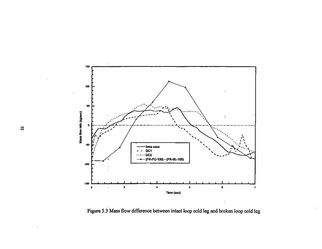
5.3 Mass flow difference between intact loop cold leg and broken loop cold leg
................ ........................................... .............. . ......... ............. 525.4 Mass flux at the core inlet junction with various discharge coefficients 53
5.5 Cladding temperature at hot core node 5 with various discharge coefficient
.................................................................. • ..................................... 54
5.6 Cladding temperature at hot core node 8 with various discharge coefficient
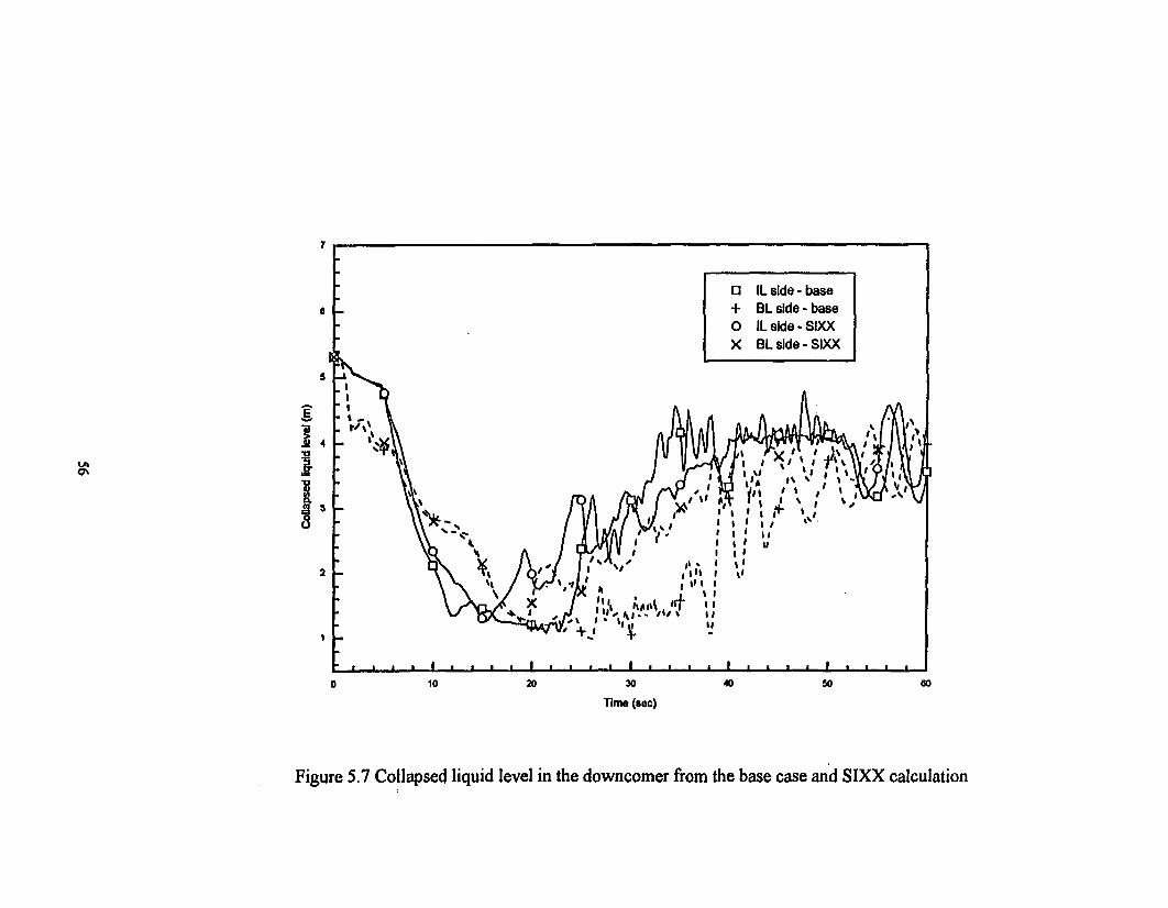
.. . o... =... °..... ..... ..... .................................................................... 555.7 Collapsed liquid level in the downcomer
from the base case and SIXX calculation .............................................. 56
5.8 Mass flux at the inlet of core in the SIXX calculation ........................... 57
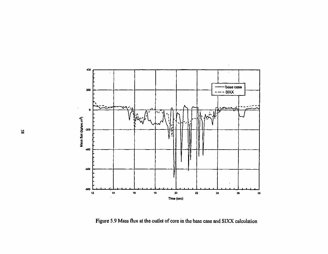
5.9 Mass flux at the outlet of core in the SLXX calculation ......................... 58
5.10 Cladding temperature at hot core node I in the SIXX calculation ......... 59
5.11 Cladding temperature at hot core node 5 in the SIXX calculation ......... 60
5.12 Cladding temperature at hot core node 10 in the SMXX calculation ....... 615.13 Mass flow rate in the broken loop cold leg by MOD3.1 and MOD3.2 ... 62
5.14 Mass flow rate in the broken loop hot leg by MOD3.1 and MOD3.2 .... 63
5.15 Cladding temperature at hot core node 2 by MOD3.1 and MOD3.2 ..... 64
5.16 Cladding temperature at hot core node 5 by MOD3.1 and MOD3.2 ..... 65
5.17 Cladding temperature at hot core node 10 by MOD3.1 and MOD3.2 ... 66
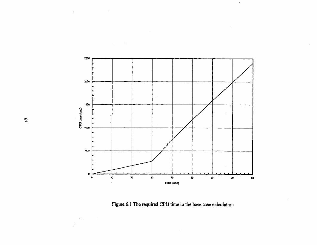
6.1 The required CPU time in the base case calculation ............................. 67
6.2 Time step size of base case calculation ................................................ 68
iv

Executive Summary
This report presents the results of RELAP5/MOD3.2 assessment in the prediction
of the thermal-hydraulic behavior under the conditions of Loss of Fluid Test(LOFT)
LBLOCA Experiment LP-02-6. The assessment was purposed to determine whether the
code can predict the major phenomena of LOFT LP-02-6 and to provide some useful
information to code developers and users.
Experiment LP-02-6 was conducted on October 3, 1983. It was the forth experi-
ment conducted in the LOFT facility at the Idaho National Engineering Labora-
tory(INEL) under the auspices of the OECD. This experiment, which was designed to
meet requirements outlined by the USNRC as specified in the OECD LOFT Project
Agreement, simulated a double-ended off-set shear of a commercial PWR main coolant
inlet pipe coincident with the loss of offsite power. Experiment LP-02-6 addressed the
response of a PWR to conditions closely resembling a USNRC "Design Basis Accident"
in that prepressurized fuel rods were installed and minimum US emergency coolant injec-
tions were used.
A base case calculation using RELAP5/MOD3.2 with the typical LOFT nodaliza-
tion and default break flow model was conducted. The results of the calculation were
compared with the experiment data in terms of loop behavior, ECCS performance, vessel
phenomena, and fuel thermal response. It was disclosed from the comparison that the
code has poor predictability of the important thermal-hydraulic phenomena such as the
early bottom up quenching during the blowdown. A primary cause of this poor predic-
tion was inferred as the overprediction of subcooled break flow. The overprediction of
subcooled break flow bring about the early end of subcooled break flow, early core heat
up during the blowdown, the early initiation of bottom-up quenching and little amount of
bottom-up flow.
To identify the effect of break flow model in the base case calculation, several cal-
culations were performed with changing discharge coefficient. It was concluded that de-
V

creased discharge coefficient reduces the peak subcooled break flow and it helps the
code better predict the early bottom up quenching.
Another sensitivity study was performed to identify the effects of the modeling of
cross flow in the split downcomer annulus. All the downcomer volumes of each side
were connected by cross flow junctions while only the top volume of downcomer annu-
lus was connected by a cross flow junction in the base case calculation. This change of
nodalization resulted in little improvement on the prediction of bottom up quenching,
which means that the core thermal-hydraulic behavior is not dependent on the number of
cross flow junctions.
Additional calculation using the RELAP5/MOD3.1 was performed to catch the
improved features of RELAP5/MOD3.2 compared with RELAP5/MOD3.1. The ver-
sions showed nearly identical results, but, RELAP5/MOD3.2 predicted better the thermal
behavior in the both end parts of the core than RELAP5/MOD3. 1.
vi

1. INTRODUCTION
This report presents the results of code assessment of RELAP5/MOD3.2 using the
LOFT experiment LP-02-6. The assessment was performed within the Code Applications
and Maintenance Program(CAMP) organized by the U. S. Nuclear Regulatory Commis-
sion(NRC).
The experiment LP-02-6 was the first large break LOCA simulation which was de-
signed to represent the design basis accident conditions. The distinguished thermal-
hydraulic phenomena of the experiment LP-02-6 is a positive bottom-up core flow,
which resulted in bottom-up quench of central fuel assembly during the blowdown period,
due to the long-term pump coast down.
The objective of this study is to identify effectiveness and deficiencies of
RELAP5/MOD3.2 in predicting thermal-hydraulic phenomenon specific to LBLOCA
such as bottom-up quenching. RELAP5/MOD3.2 is a recently released version of
RELAP5/MOD3 which was developed by improving the modeling base of
RELAP5/MOD2. RELAP5/MOD2 was assessed using the LP-02-6 test data by
Lfbbesmeyer [2]. He concluded that it could not predict the early bottom-up rewetting
which occurred between 4 and 8 seconds of the blowdown phase.
It is well known that RELAP code is very strongly dependent upon user specific
input parameters. The discharge coefficient at the break valve affects significantly on the
resultant thermal-hydraulic behavior in the analysis of LBLOCA. To find out the influ-
ence of discharge coefficient in the calculation of LP-02-6, sensitivity calculations on the
discharge coefficient were carried out.
Transversal flow in the downcomer, which has been believed to have effects on the
core flow behavior, has been modeled by cross flow junction between downcomer upper
volumes of both loop sides. A more detailed modeling of the transversal flow by connect-
ing all the volumes of both loop sides with six cross flow junctions was tried to get better
I

prediction of core flow behavior.
Finally, a calculation using RELAP5/MOD3.1 in place of RELAP5/MOD3.2 was
conducted, though it is generally thought that there is no significant change between
these versions in the analysis of LBLOCA, to get knowledge of the improved features of
RELAP5/MOD3.2.
A brief description of the LOFT system and the LP-02-6 experiment are provided
in Chapter 2. The code and modeling basis for the base case calculation is described in
Chapter 3. The results of the base case calculation are discussed in Chapter 4. The scope
and results of sensitivity studies are presented in Chapter 5. Chapter 6 describes the run
statistics for the base case calculation and conclusions and recommendations from this
assessment are presented in Chapter 7. The input list for steady-state run and transient
run of the base case is attached in Appendix.
2

2. FACILITY AND TEST DESCRIPTIONS
2.1 LOFT facility
The LOFT(Loss of Fluid Test) facility at Idaho National Engineering Laboratory
was designed to simulate the major component and system responses of commercial
PWR during LOCA. It is a scaled representation of a commercial PWR of Westinghouse
type having 4 loops with a volume ratio of 1/60. The experimental assembly includes five
major subsystems which have been instrumented such that system variables can be meas-
ured and recorded during a LOCA simulation. The subsystems consist of a reactor
vessel with a nuclear core, an intact loop, a broken loop, the blowdown suppression sys-
tem, and the emergency core coolant system. The entire nuclear core consists of five
square and four triangular fuel bundles with a total of 1300 fuel pins each of 1.67 m long
and an outside diameter of 10.72 mm. The overall configuration is shown in Figure 2.1
and complete information on this system is provided in Reference 1.
2.2 Experiment LP-02-6
Experiment LP-02-6 was completed on October 3, 1983, in the LOFT facility lo-
cated at the Idaho National Engineering Laboratory. It was the first large-break LOCA
simulation and the fourth experiment conducted under the auspices of the Organization
for Economic Cooperation and Development(OECD) LOFT Project. This experiment
simulated a double-ended offset shear of a pressurized water reactor(PWR) main coolant
inlet pipe, and was initiated from conditions similar to PWR operating conditions.
Prior to the experiment, LOFT facility was set to have a primary system pressure
of 15.0 MPa, primary system cold leg and hot leg temperature of 560K, and 590K re-
spectively, and a loop mass flow rate of 248.7 kg/sec. Initial reactor power level was 46
3

MW with a maximum linear heat generation rate (LHGR) of 48.8 kW/m. Table 2.1 pres-
ents a summary of initial conditions of the experiment.
The experiment was initiated by opening both the Quick Opening Blowdown
Valves(QOBV) in hot and cold leg. Reactor was scrammed on low hot leg pressure at
0.1 secs and the pumps were tripped at 0.8 secs. The pumps coasted down until 16.5
secs when their rotational speed fell below the trip point and they were decoupled from
their flywheels. Flow in the core reversed almost instantaneously with experiment initia-
tion, and the fuel rod cladding temperatures started to increase due to stored thermal
energy at 0.9 secs. The entire core heated up until 5.2 secs, when positive core flow was
again established due to choking of the flow in the broken cold leg. This positive core
flow quenched the lower -2/3 of the core until -10 secs when flow in the intact cold leg
decreased to below that of the broken cold leg and the core again started to heat up. A
partial top-down core quench initiated at 14.8 secs and lasted until 18.6 secs. The lower
plenum was filled by 30.7 secs, the core quench was complete by 56 secs, and core re-
flood was complete by 59 secs. Thermal-hydraulic sequence of main events observed in
the experiment is summarized in Table 2.2.
4

3. CODE AND MODELING DESCRIPTION
RELAP5/MOD3.2 used in this assessment was the very version(without any
modification) received at October 1995 from USNRC. Since any RELAP5 input spe-
cific to LP-02-6 experiment was not obtained from INEL, a reference input was devel-
oped by authors based on the input which was used in the previous LP-LB-1 assessment
by Liibbesmeyer [3].
3.1 Input Modeling
The base nodalization used to simulate the LOFT experiment LP-02-6 in this study
is shown in Figure 3.1. This nodalization and input deck are based on those used to cal-
culate the LP-LB-1 experiment with RELAP5/MOD2 by LUibbesmeyer [3]. Modifica-
tions implemented into the original input are as follows : (1) General changes suitable to
RELAP5/MOD3(e.g. heat structure), (2) Introduction of ECCMIX component, (3)
Changes in the number of volumes of pressurizer (six to twelve), (4) Changes in the
number of axial nodes of core channel, (5) LP-02-6 experiment specific modifications
The reactor vessel is modeled by three hydraulic channels representing reactor
core(volume 230, 231, and 235), two downcomer channels(volume 200 to 210 and 270
to 280 respectively), lower plenum(volume 220 to 225) and upper plenum with the ves-
sel dome(240-260). Top volumes of each downcomer channel(volume 200 and 270) are
connected with single cross flow junction(junction 290) which has energy loss coefficient
of 1.8341. Nozzle bypass from intact cold leg to upper plenum is also modeled. The core
is modeled by 3 parallel channels; core bypass channel(volume 235) with 3 subvolumes,
average and hot core channel(volume 230 and 231) subdivided into 12 equally spaced
volumes respectively. It is assumed that the total mass flow rate through the core is
shared approximately 79%/a by the average channel, 16% by the hot channel and 5% by
5

core bypass channel. The heat generated in the fuel pin is transferred to primary coolant
by heat structures attached to the hot channel and the average channel. To include the
effect of heat capacity of material, heat structures of the downcomer and lower plenum
are modeled.
The intact loop consists of twenty volumes with several subvolumes. The pumping
system is divided into two pump lines with two individual pumps numbered as 135 and
165 respectively.
The ECC injection system consists of five volumes and one valve. This system is
connected to the intact loop cold leg volume modeled by the ECCMIX compo-
nent(volume 185). The -PIS and LPIS are modeled by time dependent junctions num-
bered 635 and 625 respectively. Control valve(valve 610) in the accumulator line is to
isolate the accumulator when the accumulator is emptied.
The steam generator consists of eight volumes on the primary system and fifteen
volumes on the secondary system. Heat is exchanged between primary and secondary
side of the steam generator via the u-tubes which is modeled by heat structures. Feed
water system and steam condenser are modeled by time dependent volumes(volume 505
and 541, respectively). Feed water flow rate and steam flow rate are controlled by con-
trol logic to keep the required secondary pressure and level.
The pressurizer is modeled by surge line(volume 400 and 402), pressurizer ves-
sel(volume 415) and pressurizer dome(volume 420). Pressurizer vessel was divided into
twelve subvolumes.
The broken loop hot leg is modeled by four volumes(volume 300 to 315). Compo-
nent 315 represents steam generator simulator. The broken loop cold leg is modeled by 4
volumes(volume 335 to 344). Reflood assist bypass line is modeled by 2 volumes(volume
370 and 380). The reflood assist bypass valve is modeled by a trip valve which is closed
when the break valves are opened. At the end of each broken loop, two break valves
which have to be opened by trip signal are placed and connected with the suppression
6

tank modeled by two time dependent volumes(700 and 705). The discharge coefficients
of the break valves are 1.0 for the subcooled discharge and the saturated discharge.
In the input modeling delineated above, total number of hydrodynamic volumes,
junctions and heat structures are 147, 152, and 47, respectively.
3.2 Initial and Boundary Conditions
To obtain the initial conditions proper to the test conditions over the whole system,
a steady state calculation was performed with four steady state controllers and a time
dependent volume : two primary coolant pump speed controllers, a charging and letdown
controller, a feed water flow rate controller, and a time dependent volume to set pressur-
izer pressure to a designed value.
The results obtained from the steady state run were compared with the measured
initial conditions [4] in Table 2.1. The calculated results generally agree with the experi-
mental conditions except the broken loop hot leg temperature which was estimated lower
than the measured data. The reason of such underprediction of the broken loop hot leg
temperature was not clear, but, it was believed to have negligible effect on the overall
system transient.
Based on the experiment data, the reactor power history, containment pressure
and feedwater flow rate after scram were described as time dependent tables. Perform-
ance curves for HPSI and LPSI flow rate as function of cold leg pressure were provided
in the input. The pump speed after trip was simulated by time dependent speed table.
And the steam generator secondary side air-cooled condenser was modeled as a time
dependent volume with a constant pressure of 2.069 MPa during the transient. All infor-
mation of boundary conditions was provided in the steady and transient input deck.
7
4. RESULTS FROM BASE CASE CALCULATION
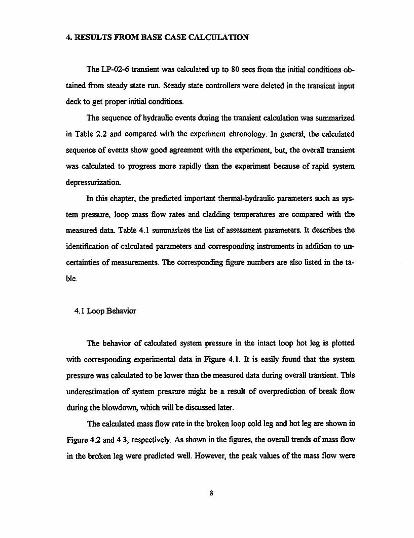
The LP-02-6 transient was calculated up to 80 secs from the initial conditions ob-
tained from steady state run. Steady state controllers were deleted in the transient input
deck to get proper initial conditions.
The sequence of hydraulic events during the transient calculation was summarized
in Table 2.2 and compared with the experiment chronology. In general, the calculated
sequence of events show good agreement with the experiment, but, the overall transient
was calculated to progress more rapidly than the experiment because of rapid system
depressurization.
In this chapter, the predicted important thermal-hydraulic parameters such as sys-
tem pressure, loop mass flow rates and cladding temperatures are compared with the
measured data. Table 4.1 summarizes the list of assessment parameters. It describes the
identification of calculated parameters and corresponding instruments in addition to un-
certainties of measurements. The corresponding figure numbers are also listed in the ta-
ble.
4.1 Loop Behavior
The behavior of calculated system pressure in the intact loop hot leg is plotted
with corresponding experimental data in Figure 4.1. It is easily found that the system
pressure was calculated to be lower than the measured data during overall transient. This
underestimation of system pressure might be a result of overprediction of break flow
during the blowdown, which will be discussed later.
The calculated mass flow rate in the broken loop cold leg and hot leg are shown in
Figure 4.2 and 4.3, respectively. As shown in the figures, the overall trends of mass flow
in the broken leg were predicted well. However, the peak values of the mass flow were
8

highly overestimated to be about 741 kg/sec (the measured value is -550 kg/sec) in the
cold leg and 241 kg/sec (the measured value is -193 kg/sec) in the hot leg. Such an
overprediction of mass flow rate in the broken loop in the early period of transient is
considered as a deficiency of RELAP5/MOD3.2 critical flow model. This might lead the
intact loop to contain less inventory than the experiment.
The calculated mass flow rates in the intact loop cold leg and the intact loop hot
leg were compared with the experimental data in Figure 4.4 and 4.5, respectively. It can
be found that the calculated mass flow rates followed the trend of the measured data very
well with slight underestimation of mass flow rate in the cold leg during the blowdown
phase.
The mass flow rate in the broken loop cold leg was predicted to fall below the
mass flow rate in the intact loop cold leg at -3.3 sees as shown in Figure 4.6. The fact
that the mass flow rate in the broken loop cold leg is lower than the mass flow rate in the
intact loop cold leg means that the flow in the broken loop cold leg is saturated and the
core is being filled with fluid from the intact loop cold leg. The phase transition of flow
in the broken loop cold leg was observed at -4 secs after transient initiation in the ex-
periment.
4.2 ECCS Performance
Figure 4.7 shows the calculated accumulator pressure and Figure 4.8 shows the
predicted liquid level in the accumulator with corresponding measured data. As shown in
these figures, the accumulator injection was initiated at -14.5 secs while it was started at
17.5 secs in the experiment. This earlier accumulator injection was resulted from rapid
system depressurization.
Figure 4.9 shows the calculated LPSI mass flow rate with the measured data. The
injection was predicted to be earlier and higher than the measured data. This earlier and
9

higher injection was also due to the underestimation of the primary system pressure dur-
ing the injection period.
4.3 Vessel Phenomena
Figure 4.10 shows the calculated liquid temperature in the lower plenum. The liq-
uid temperature was underperdicted after -14 secs when the accumulator injection was
initiated -3 secs earlier than the experiment as stated in the previous section.
Figure 4.11 presents the collapsed liquid level in the two downcomer channels and
the two core channels of reactor vessel. Since no experiment data for these collapsed
liquid levels were available, the predicted levels are plotted only.
The liquid level in the core decreased rapidly after initiation of break and the core
was completely emptied at -3 secs until bottom up flow was initiated. The filling of the
core with the bottom up flow was predicted to make the lower part of the core rewet.
And then, the liquid level fell again below the bottom of core and was maintained low
level until the ECC injection water reached the bottom of core at -38 secs. The hot core
reflood was completed at 64 secs, -5 secs latter than the experiment.
In the early blowdown period up to -3 secs, the liquid level in the broken side
downcomer dropped more rapidly than that in the intact side one due to less flow resis-
tance. The liquid level in the broken side downcomer increased for a short time from the
end of subcooled blowdown because the break flow was reduced significantly due to
saturation while the incoming flow from the intact loop cold leg was still maintained.
During the core rewetting period, the liquid levels in the both sides decreased again. The
decreasing rate of the broken side liquid level was smaller than that in intact side. This
was due to upward water flow from the lower plenum to the broken side downcomer.
The level in the intact side downcomer started to increase at -22 secs mainly due to ac-
cumulator injection flow initiated at 14.5 secs. The level in the broken side downcomer
10

also started to increase at -26 secs.
4.4 Fuel Thermal Response
Calculated cladding temperatures of hot rod at 12 axial hot core nodes are com-
pared with the measured data of corresponding elevation in Figure 4.12 to Figure 4.23.
From the comparison of the cladding temperature behavior, following features are ob-
served.
1) The blowdown heat up was relatively well predicted over the core except at the
highest node, but, it was calculated to occur little earlier than the measured data.
2) The blowdown heat up was underpredicted at the low heat flux region, and
overpredicted at the high heat flux region. In the middle part of the core, the
degree of overestimation is -60K at the hottest elevation.
3) The early bottom-up quenching was predicted to occur at the 1/4 lower part of
the core, while it was observed at the -2/3 lower part of the core in the experi-
ment. Even more, it was calculated to be initiated slightly earlier than the meas-
ured data. This prediction of earlier and little amount of bottom up quenching
resulted from the overestimated peak mass flow rate in the broken loop cold leg,
i.e. cold leg break flow and the early end of subcooled blowdown as mentioned
in section 4.1.
4) The calculated second heat up was also calculated to start earlier than the
measured data due to earlier bottom-up quenching.
The peak cladding temperature(PCT) during the blowdown phase in the core was
calculated to occur at the elevation of 22 to 27.5 inches(node 5) while it was measured at
27 inches from the bottom of core. The calculated PCT is 1121 K, which is -50 K higher
I1

than that measured in the experiment. The calculated maximum cladding temperature
during the reflood phase was approximately 960 K while it was 831 K in the experiment.
Such an overestimation is a result from the deficiency of RELAP5/MOD3.2 not to be
able to predict the early bottom-up quenching in the middle part of the core.
12

5. SENSITVITY STUDIES
To investigate the influence of discharge coefficient on the resultant cladding tem-
perature behaviors, two additional calculations were carried out. A brief note of these
calculations is as follows :
calculation ID subcooled discharge coeff. saturated discharge coeff.
DC1 1.1 1.1
(Base case) (1.0) (1.0)
DC2 0.9 0.9
And to find out the effects of the cross flow junction between the intact side
downcomer and the broken side downcomer, an additional calculation was performed
with six cross flow junctions between all the volumes of both sides. The sum of mass
flow through the cross flow junctions before the initiation of transient in the calculation
is made to be nearly equal to that in the base case calculation by adjusting the energy loss
coefficients of junctions. For the convenience of later discussion, the calculation was
named SIXX.
Finally, a calculation using RELAPS/MOD3.1 was conducted to identify the ef-
fects of improved features of RELAP5/MOD3.2 for the LBLOCA analysis.
5.1 Influence of Discharge Coefficient
In Figure 5.1 and 5.2, the calculated mass flow rates in the broken loop cold leg
and hot leg with various discharge coefficients are presented for comparison. These fig-
ures show that the mass flow rate in each broken leg during the blowdown is highly de-
13

pendent on the discharge coefficient.
Figure 5.3 contains the difference between mass flow rate in the intact loop cold
leg and mass flow rate in the broken loop cold leg, and Figure 5.4 presents the calculated
bottom-up core mass flux at the hot core inlet junction induced by the mass flow differ-
ence. From these figures, it can be found that the bottom-up core flow in the blowdown
phase is dominated by the discharge coefficient at the break and the smaller discharge
coefficient, in other words, the lower break flow induces the higher bottom-up core flow.
This correlation between the discharge coefficient and the bottom-up core flow
can be made clear by Figure 5.5 and 5.6, which show the calculated cladding temperature
behaviors at the hot core node 5 and 8, respectively. As shown in the figures, the more
break flow rate was estimated in the blowdown phase, the less bottom-up quenching was
predicted.
5.2 Influence of Cross Flow Modeling in the Downcomer
Figure 5.7 contains the calculated downcomer liquid levels both in the base case
calculation and in the SIXX calculation. From the figure, one can find that the liquid lev-
els of both sides of downcomer predicted in the calculations showed almost similar trend.
The difference between the base case and SIXX calculation for the core bottom-up
flow is shown in Figure 5.8 As shown in the figure, the initiation and completion of bot-
tom-up flow in the SIXX calculation was predicted to be little later than those in the base
case, and the total bottom-up flow in the SIXX calculation is considered somewhat
greater than that calculated in the base case calculation. Such a delayed and larger bot-
tom-up flow resulted in lower and delayed second heat up.
Figure 5.9 shows the mass flux at the outlet of the core. The calculated top-down
quenching flow in the base case was higher than that predicted in the SDCX calculation.
14

However, the cladding temperature behavior predicted in the both calculations didn't
show any significant difference because the differences of flow behavior were not so
large. The cladding temperature behaviors at hot core node 1, 5, and 10 are presented in
Figure 5.10 to 5.12.
In conclusion, the hydraulic and thermal behavior in the core calculated by
RELAP5/MOD3.2 was not strongly dependent on the number and position of the cross
flow junctions in the downcomer.
5.3 Calculation Using RELAP5/MOD3.1
A calculation similar to the base case using RELAP5/MOD3.1, for which we
didn't make any change after it was received at October in 1993 from USNRC , was
performed to identify the difference between RELAP5/MOD3.1 and RELAP5/MOD3.2
for LBLOCA analysis.
The calculated hydraulic behavior by RELAP5/MOD3.1 is very similar to that
predicted by RELAP5/MOD3.2. The mass flow rates in the broken loop cold leg and hot
leg, for instance, showed nearly same trend as shown in Figure 5.13 and Figure 5.14.
However, the cladding temperatures predicted by RELAP5/MOD3.1 showed less degree
of heat up both in the blowdown phase and the reflood phase than those by
RELAP5/MOD3.2. The cladding temperatures calculated by RELAP5/MOD3.1 at sev-
eral elevations are presented in Figure 5.15 to Figure 5.17 with corresponding data by
RELAP5/MOD3.2. More profound studies of these results were not tried because the
predicted cladding temperature behavior by RELAP5/MOD3.1 and RELAP5/MOD3.2
showed no dramatic difference.
15
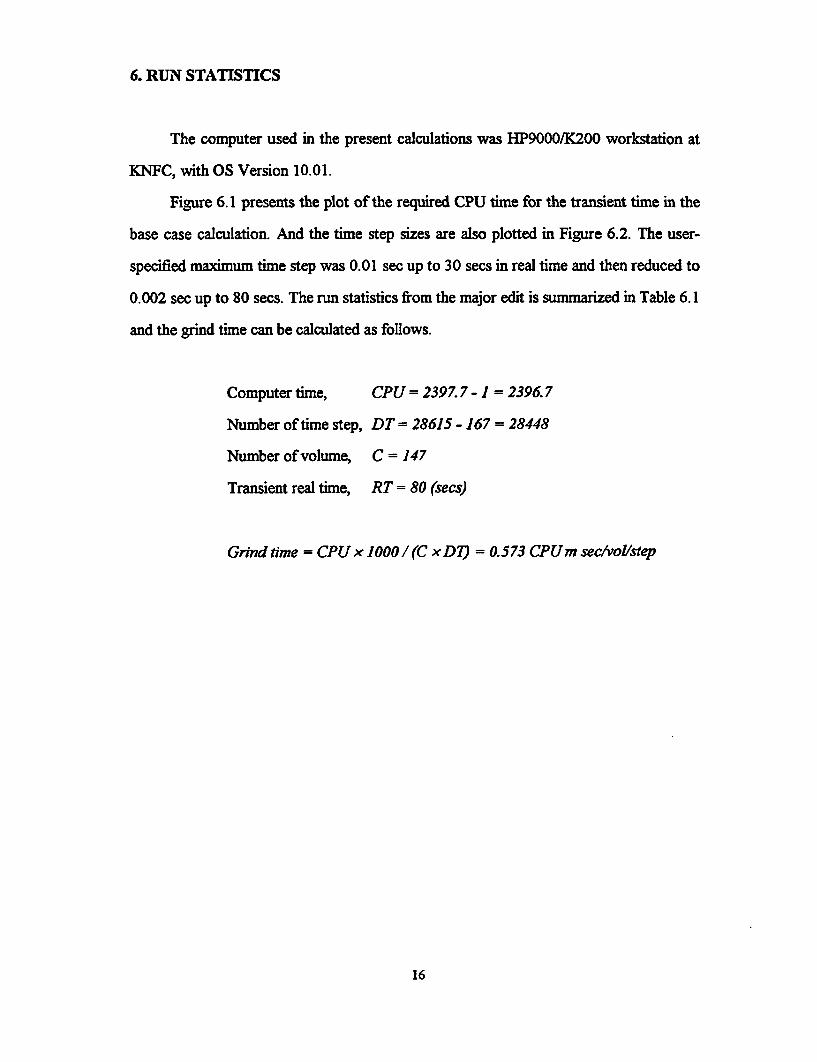
6. RUN STATISTICS
The computer used in the present calculations was HP9000/K200 workstation at
KNFC, with OS Version 10.01.
Figure 6.1 presents the plot of the required CPU time for the transient time in the
base case calculation. And the time step sizes are also plotted in Figure 6.2. The user-
specified maximum time step was 0.01 sec up to 30 secs in real time and then reduced to
0.002 sec up to 80 secs. The run statistics from the major edit is summarized in Table 6.1
and the grind time can be calculated as follows.
Computer time, CPU = 2397.7 - 1 = 2396.7
Number of time step, DT = 28615 - 167 = 28448
Number of volume, C = 147
Transient real time, RT = 80 (secs)
Grind time = CPU x 1000/(C xD7) = 0.573 CPUm sec/vol/step
16

6. CONCLUSIONS AND RECOMMENDATIONS
RELAP5/MOD3 code was assessed using LOFT LP-02-6 test data. A base case
calculation using RELAP5/MOD3.2 was carried out as a reference case. Discharge coef-
ficient sensitivity studies were performed to investigate the influence of this user-specific
parameter in the analysis of LBLOCA. A more detailed modeling of cross flow in the
inlet annulus and downcomer volume was tried to improve the code predictability of
early bottom-up quenching in the blowdown phase. As a final case, a calculation using
RELAP5/MOD3.1 was performed to identify the differences between RELAP5/MOD3.1
and RELAP5/MOD3.2. Based upon the results from the scope of this study, the follow-
ing conclusions were made.
1) Using LOFT LBLOCA test data LP-02-6, a base calculation with a standard
nodalization was successfully performed and matched relatively well with the
experimental data.
2) RELAP5/MOD3.2 with standard nodalization can predict system hydraulic be-
havior. However the mass flow rates in the broken loop cold leg and hot leg
during the subcooled blowdown were largely overestimated.
3) RELAP5/MOD3.2 can predict well the blowdown heat up of the core. How-
ever, the calculated blowdown heat up was initiated slightly earlier than the ex-
periment due to the poor prediction of heat transfer in the fuel rod during blow-
down. The calculated PCT was predicted to be -50K higher than the measured
data.
4) The bottom-up quenching in the middle part of hot core was not predicted
17

properly by RELAP5/MOD3.2, therefore, the maximum cladding temperature
during the reflood phase was highly overestimated to be about 960 K.
5) RELAP5/MOD3.2 was so sensitive to the discharge coefficient that the resul-
tant behavior of cladding temperatures was greatly varied with small change of
discharge coefficient. The development of more accurate break flow model,
which is known to be undergoing, should be made to remove the sensitiveness
to this user accessible parameter.
6) From our analysis of cross flow modeling in the downcomer volume, it was re-
vealed that the core flow behavior is not dependent on the position and number
of cross flow junctions connected. In other words, single cross flow junction
with a low energy loss coefficient and multiple cross flow junctions with a high
energy loss coefficient might have similar effect on the resultant thermal behav-
ior in the core.
7) Neither of code versions, RELAP5/MOD3.1 and RELAP5/MOD3.2, could
predict properly the early bottom-up quenching in the middle part of the core.
The only effect of improved features of RELAP5/MOD3.2 could be shown in
the lower part of core, where RELAP5/MOD3.2 could predict the blowdown
heat up better than RELAP5/MOD3.1.
8) It was revealed that RELAP5/MOD3 can be used as a best estimate tool for
analysis of LBLOCA with the improvement of break flow model which has
great influence on the predictability of early bottom-up quenching in the
LBLOCA.
18

REFERENCES
[1] LOFT System and Test Description, Reeder, D.G., NUREG/CR-0247 Tree-
1208, 1978(update 9/80)
[2] Post-Test-Analysis and Nodalization Studies of OECD LOFT Experiment LP-
02-6 with RELAP5/MOD2 cy 36-02, D. Lilbbesmeyer, Draft to NUREG
Report
[3] Post-Test-Analysis and Nodalization Studies of OECD LOFT Experiment LP-
LB-i with RELAP5/MOD2 cy 36-02, D. Liibbesmeyer, NUREG/IA-0089,
October 1992
[4] Quick-Look Report on OECD LOFT Experiment LP-02-6, J.P.Adams,
K.G.Condie, D.L.Blatt, OECD LOFT-T-3404, October 1993
[5] RELAP5/MOD3 code manual, The RELAP5 Development Team,
NUREG/CR-5535, August 1995
[6] TRAC-PF1/MOD1 Calculation of LOFT Experiment LP-02-6, P.Coddington,
C.Gill, NUREG/IA-0027, April 1992
19

Table 2.1 Initial and boundary conditions for experiment LP-02-6
Parameter Measured CalculatedData value
Power(MW)
Temperature Across Core(K)
Hot Leg Pressure(MPa)
Cold Leg Temperature(K)
Mass Flow Rate(Kg/s)
Pressurizer
Liquid Level(m)
Water Temperature(K)
Pressure(MPa)
Broken Loop
Cold Leg Temperature(K)
Hot Leg Temperature(K)
Emergency Core cooling System
Accumulator Liquid Level(m)
Accumulator Pressure(MPa)
Accumulator Liquid Temperature(K)
High Pressure Injection Flow Rate(l/s)
High Pressure Injection Liquid Temperature(K)
Low Pressure Injection Flow Rate(l/s)
Low Pressure Injection Liquid Temperature(K)
46.0±1.2
33.1±1.1
15.09±0.08
555.9±1.1
248.7±2.6
1.04±0.04
615.6±5.8
15.3±0.11
553.0±6.0
560.0±6.0
2.10±0.0
4.11±0.06
302. ±6.1
1.04±0.04
305. ±7
a
305. ±7
46.0
33.57
15.10
555.98
248.69
1.041
615.76
15.09
555.8
555.9
2.10
4.11
302.
1.04
305.
a
305.
a. Depending on pressure difference between LPIS and downcomer
20

Table 2.2 Chronology of event for experiment LP-02-6
Event Measured CalculatedData value
(seconds) (seconds)
Blowdown Valve Open 0.0 0.0
Reactor Scrammed 0.1 0.1
Primary Coolant Pumps Tripped 0.8 0.8
Cladding Temperature Initially Deviated from
Saturation 0.9 0.5
End of Subcooled Break Flow 4.0 3.3"
Blowdown Peak Cladding Temperature Reached 4.9 3.8
Bottom-up Core Rewet Initiated 5.2 3.7
Bottom-up Core Rewet Completed 9.1 13.0
Partial Core Top-down Quench Initiated 14.8 14.5
Pressurizer Empty 15.5 14.0
Accumulator Injection Initiated 17.5 14.05
Partial Core Top-down Quench Completed 18.6 24.6
High Pressure Injection Initiated 21.8 21.8
Lower Plenum Refill Completed 30.7 32.
Low Pressure Injection Initiated 34.8 34.8
Reflood Peak Cladding Temperature Reached 41.0 26.3
Accumulator Injection Completed 57.0 50.0
Core Quench Completed 56.0 60.5
Core Reflood Completed 59.0 64.0
a. This value is based on the time when the junction void fraction in the cold legbreak valve is less then 0.1
b. The measured time for complete refill of the lower plenum is based on when thelowest fuel rod cladding quenched.
21

Table 4.1 List of assessment parameters (LOFT LP-02-6)
Description Calculation Measurement Uncertainty Figure
Primary SystemPressureBLCLMass Flow RateBLHLMass Flow RateILCLMass Flow RateILBLMass Flow RateDowncomerFluid TemperatureLower PlenumFluid TemperatureLPISMass Flow RateCladding Temperature(Central 2 inches)Cladding Temperature(Central 5 inches)
Cladding Temperature(Central 8 inches)Cladding Temperature(Central 11 inches)Cladding Temperature(Central 15 inches)
Cladding Temperature(Central 21 inches)
Cladding Temperature(Central 24 inches)Cladding Temperature(Central 26 inches)
Cladding Temperature(Central 27 inches)
Cladding Temperature(Central 28 inches)Cladding Temperature(Central 30 inches)
p 112-01
mflowj 340-01
mflowj 305-01
mflowj 175-01
mflowj 112-01
tempf 210-02
tempf 220-01
mflowj 630-00
httemp 231-01
httemp 231-01
httemp 231-02
httemp 231-02
httemp 231-03
httemp 231-04
httemp 231-05
httemp 231-05
httemp 231-05
httemp 231-06
httemp 231-06
PE-PC-002
FR-BL-105
FR-BL-205
FR-PC-100
FR-PC-205
TE-IST-002
TE-5LP-001
FT-P120-085
TE-5H02-002
TE-5I06-005TE-5J04-005
TE-5H07-008
TE-5G06-01 1
TE-5F04-015TE-5HO5-0lsTE-5M07-015
TE-5304-021TE-5J06-021
TE-5H106-024
TE-5F04-026TE-5F08-26TE-5108-026TE-5J06-026TE-5M07-026
TE-5D)07-027TE-5I04-027
TE-5H106-028
TE-5006-030
0.036 MPa
Not found
5.1 K
5.1K
0.25 1/s
5.2 K
if
4.1
4.2
4.3
4.4
4.5
4.6
4.7
4.8
4.12
4.12
4.13
4.13
4.14
4.15
4.16
4.16
i
ff
it
ff
if
if
if
if
if
if
if
4.16
4.17
4.17
'I
22

Table 4.1 List of assessment parameters (Continued)
Description Calculation Measurement Uncertainty Figure
Cladding Temperature(Central 31 inches)
Cladding Temperature(Central 32 inches)
Cladding Temperature(Central 37 inches)Cladding Temperature(Central 39 inches)
Cladding Temperature(Central 41 inches)Cladding Temperature(Central 43.8 inches)
Cladding Temperature(Central 45 inches)Cladding Temperature(Central 49 inches)Cladding Temperature(Central 54 inches)
Cladding Temperature(Central 58 inches)Cladding Temperature(Central 62 inches)
httemp 231-06
httemp 231-06
httemp 231-07
httemp 231-08
httemp 231-08
httemp 231-08
httemp 231-09
httemp 231-09
httemp 23 1-10
httemp 231-11
httemp 231-12
TE-5C07-03 1TE-5D07-03 1
TE-5F04-032TE-5H06-032TE-5M07-032
TE-5H06-037
TE-5106-039TE-5104-039
TE-5H07-041
TE-5C07-43.8TE-5104-43.8
TE-5G06-045
TE-51105-049
TE-5I06-054TE-5J04-054
TE-5H07-058
TE-5F04-062TE-5006-062
5.2 Kn
4.17
4.17
if
if
if
'I
if
if
if
ft
I,
iv
4.18
4.19
4.19
4.19
4.20
4.20
4.21
4.22
4.23
23

Table 6.1 Run statistics data in base case
Attempted Repeated LastTransient time
(sec)
0
10
20
30
40
50
60
70
80
CPU time(sec)
1.00
94.46
189.78
291.52
784.41
1229.55
1676.05
1995.11
2397.70
AttemptedADV
0
1011
2011
3106
8613
13615
18615
23615
28615
RepeatedADV
0
3
3
3
166
167
167
167
167
LastDT
0.01
0.01
0.01
0.01
0.002
0.002
0.002
0.002
0.002
CourantDT
0
1.11175-2
9.57746-3
1.17485-2
1.06071-2
1.84512-2
1.65845-2
4.72061-2
1.38078-2
24

Intact Loop
BL-Iexperimontal
Broken Loop
IA
INEL-LP-02.6 1505 Reactor vessel
Figure 2.1 LOFT major component

S/I Secondary Side.7 /500]
420
Pressurizer/400.
616
415
Reactor Vessel/200/1 Broken Loop.
/300]
09
280
ECCS/600]
Figure 3.1 Schematic diagram of standard nodalization

I
0 10 20 30 40 50
Time (sec)
Figure 4.1 System pressure in the intact loop hot leg
w0

746 kg/sec
8o
-00 _mflowj 340-01-a-- FR-BL-105
600
00 300-
I:
200
iWi
00
0 10 20 30 40 50 60
Time (sec)
Figure 4.2 Mass flow rate in the broken loop cold leg

217 kg/sec
250
150
100
so
0
%0
0 10 20 30 40 50 80
Time (sec)
Figure 4.3 Mass flow rate in the broken loop hot leg

300
20D
(.J
I100
0
.100
0 10 20 30 40 50 60
1 Time (sec)
Figure 4.4 Mass flow rate in the intact loop cold leg

400
300
3200
AEU
0
0 10 20 30 40
Time (sec)
80
Figure 4.5 Mass flow rate in the intact loop hot leg

O0W
500
400
~300
~200
W•t4J
100
0
-100
0 10 20 30 40 50 60
Time (sec)
Figure 4.6 Mass flow in the broken loop cold leg and the intact loop cold leg

4
3
W II
10 20 30 40 50 80
Time (see)
Figure 4.7 Accumulator pressure

2.2
4•
2.0
1.8
1 .8
1.4
1,2
1.0
10 20 30 40
Time (sec)
60
Figure 4.8 Acummulator liquid level

a
L4 4
2
0
0 10 20 30 40 50
Time (sec)
s0
Figure 4.9 LPIS discharge flow rate

650
g
0'
4W0
3500 10 20 30 40 50
Time (sec)
60
Figure 4.10 Fluid temperature in the lower plenum

6
M OL aowncomer0 average core
E hot core
4 "i
- J I
I!: ' •1 11.o I ll J ll$12I l',I
IN , 0 1 , Bottom of core. . . . .. . . . I ...5 .. . . . . . . . . . . . . . . . . . . . . . . . . . . . . . . . . . . . . . .
0 10 20 30 40 50 e0 70 80
Time (sec)
Figure 4.11 Collapsed liquid levels in the downcomer and core channels

aw
800 -0-TE
700
E0 __L0 0 0
Cooo DO- )a000O
I ,
40
0 10 20 30 40 U
Time (see)
Figure 4.12 Cladding temperature at hot core node I
60

1000
900
800
160
g700
000
500
400
0 10 20 30 40 50
lime (sec)
60
Figure 4.13 Cladding temperature at hot core node 2

0
gaLb2I-
1100
1000
800
800
700
6am
500
400
0 10 2D 30 40 5o 6o
Time (sec)
Figure 4.14 Cladding temperature at hot core node 3

46gE
I.-
1200
1100
1000
000
a0
700
a0
500
400
0 10 20 30 40 so
Time (sec)
60
Figure 4.15 Cladding temperature at hot core node 4

1200
1100
1000
EA-
8OO
000
500
400
0 10 20 30 40 50 60
Time (sec)
Figure 4.16 Cladding temperature at hot core node 5
70

1200
1100
900
I.I- 700
600
500
0 10 20 30 40 50 60 70
Time (sec)
Figure 4.17 Cladding temperature at hot core node 6

t
gz
800
600
700
400
500
400
0 10 20 30 40 50 60
Time (sec)
Figure 4.18 Cladding temperature at hot core node .7
70

1100
1000
Ow0
tA
g
I.am0
700
am0
5M0
0 10 20 30 40 50 60
lime (sec)
Figure 4.19 Cladding temperature at hot core node 8
70

1000
4ý5% I-
800
700
800
5OO
400
0 10 20 30 40 50 60 70
Time (sec)
Figure 4.20 Cladding temperature at hot core node 9

900
80o
700
500
400
0 10 20 30 40 50
Time (see)
80
Figure 4.21 Cladding temperature at hot core node 10

6OO
750
700 - httemp 231-11
.... TE-5HO7-058
0d
550
450
d.
40000
0 10 20 30 40 50 60
Time (see)
Figure 4.22 Cladding temperature at hot core node 11

750
700
650
eoo
550
500
'50
400
0 10 20 30 40 50 60
lme (Sec)
Figure 4.23 Cladding temperature at hot core node 12

800
700
800
%500
~400
~300
200
100
0
l.A0
0 5 10 I5 20 25 30
Time (sec)
Figure 5.1 Mass flow rate in the broken loop cold leg with various discharge coefficients

250
L.A
200
jISO
p100
50
50
30
Time (sec)
Figure 5.2 Mass flow rate in the broken loop hot leg with various discharge coefficients
150
tA
100
50
0.50
.100
-150$ 4 5 7
Time (sec)
Figure 5.3 Mass flow difference between intact loop cold leg and broken loop cold leg

800
am
LtLI
Sg200
0
-200
.400
a 8 10 12 14Time (sec)
Figure 5.4 Mass flux at the core inlet junction with various discharge coefficients

a.A I
1zoo
1100
1000
900
80o
700
60o
500
400
0 10 20 30 40 50 60
Time (sea)
Figure 5.5 Cladding temperature at hot core node 5 with various discharge coefficients

1100
1000
900
700
60O
am0
LA
g
0 10 20 30 40 50
Tlime (sec)
60
Figure 5.6 Cladding tempeature it hot core node 8 with various discharge coefficients
7
a
a
i
2
0 10 20 30 40 so 60
Time (sec)
Figure 5.7 Collapsed liquid level in the downcomer from the base case and SIXX calculation

800
O00
400
-200
0
-200
2 4 8 10 12
Time (see)
Figure 5.8 Mass flux at the inlet of core in the base case and SIXX calculation
14
200
0
.400
0000
40012 14 16 18 20 22 24 26
Time (sec)
28
Figure 5.9 Mass flux at the outlet of core in the base case and SIXX calculation

900
Va
700
5O0
0 10 20 30 40 50 60
Time (sec)
Figure 5.10 Calculated cladding temperature at hot core node I in the SIXX calculation

1200
1100
1000
700
8000
500
400
10 20 30 40
Time (see)
00
Figure 5.11 Cladding temperature at hot core node 5 in the SIXX calculation

900
800
700
5e00
400
0 10 20 30 40 50 80
Time (sec)
Figure 5.12 Cladding temperature at hot core node 10 in the SIXX calculation

800
700
400
300
200
100
0
0•
0 10 20 30 40 50 60
Time (sec)
Figure 5.13 Mass flow rate in the broken loop cold leg by MOD3.1 and MOD3.2

250
0%w~
200
150
~100
so
50
0 10 20 30 40 50 60
Time (eec)
Figure 5.14 Mass flow rate in the broken loop hot leg by MOD3.1 and MOD3.2

1000
Boo
800
ag600
800
400
0 10 20 30 40 50
Time (sec)
60
Figure 5.15 Cladding temperature at hot core node 2 by MOD3.1 and MOD3.2

LAON
12W0
1100
9OO
BOO
700
000
900
400
0 10 20 30 40 50
Tlme (sec)80
Figure 5.16 Cladding temperature at hot core node 5 by MOD3.1 and MOD3.2

@1
I-
boo
750
700
650
000
550
500
450
400
0 I0 20 30 40 50 60
Time (sec)
Figure 5.17 Cladding temperature at hot core node 11 by MOD3.1 and MOD3.2
25W
0 100%-J
00 10 20 30 40 50 60 70
Time (sec)
s0
Figure 6.1 The required CPU time in the base case calculation

a%O0CL
P-
0.08
0.07
0.08
0.06
0.04
0.03
0.02
0.01
0.000 10 20 30 40 50 60 70
Time (sec)
80
Figure 6.2 Time step size of base case calculation

APPENDIX : INPUT LISTING
69


S.************** **********S * *5* * **5* *** ** **5*5*****5*** ** ** **
* STEADY-STATE INPUT FOR LP-02-6 (Base Case)
* CODE VERSIONS : MOD3.2* DISCHARGE COEFFICIENTS AT 1I1E BREAK VALVES: 1.0, 1.0
* JODIFIED AT 6/25/96* EDITOR : T. S. CHOI
*---....1--------.1-.......-1........1--------.1-- -... 1----
100 new stdy-st101 run105 5.0 10.0 * No CPU time limit110 nitrogen
* time step control cards* end time min dt max dt optn mnr mir rst
201 1.+5 1.0-6 0.1 14003 1000 5000 5000*5**5****55*5****55****5******5****.*.*****************************
* trips
*55*55*.5****5.5**5**55**.**5**5..5****55******.*5*5**55***5******- -.....1-.......1. ..... ....... * ..........-... 1
* 500 end of job trip
500 time 0 ge null 0 3000. I600 500
* 501 always true
501 time 0 ge null 0 -1.0 I
* 501-515 test specific trips
* break open510 time 0 ge null 0 1500.0 I
* scram511 time 0 ge timeof 510 0.13 1* pcp trip512 time 0 ge timeof 510 0.0 I* hpsi on513 time 0 ge timeof 510 21.8 I* broken leg bypass514 time 0 ge null 0 1.0+9 I
* accumulator valve515 p 620010000 ge p 185010000 0.0 1* Ipsi on516 time 0 ge timeof 510 34.8 I* reflood555 time 0 ge timeof 510 1.0+6 I
* difference related trips
* It 681 reflood bypass valve card 3750301
681 -510 and -510 n
* It 682 accumulator valve card 6100301
582 cntrlvar 4 It null 0 1.-3 I682 -582 and 515 n*--- -1--------.1--------.1--------.I--.......I--------.1-....
* It 685-686 steam valve card 5400301 : L2-5
* open trip589 p 530010000 gt null 0 7.12+6 n590 p 530010000 It null 0 6.98+6 n670 685 or 589 n671 -590 and -686 n685 671 and 670 n* close trip591 p 530010000 gt null 0 6.57+6 n592 p 530010000 It null 0 6.50+6 n672 686 or 592 n673 -591 and 672 n674 -685 and 511 n686 673 and 674 n
* job termination valve trip
* open687 685 or 685 n* close688 686 or 686 n
** nta* loop** 100*** ************ *************5*******5*5*5*5**
* intact loop [1001
- Al -

1 ... ... 1 -.. ... 1 . .... --- . . ... -- - ---- .. --- .. . . .--- --- ...--* reactor vessel nozzle - intact loop hot leg
1000000 rvnilhl branch1000001 2 01000101 0.0 1.58878 0.102752 0.0 0.0 0.01000102 4.0-5 0.0 010001000200 0 1.51702+7 1415050. 2455780. 0.01001101 252010000 100000000 0.0634 0.1 0.1 00021002101 100010000 105000000 0.0 0.1 0.1 00001001201 5.7156000 6.0302000 0.01002201 5.6978000 5.6978000 0.0S. .-1--- ----1 . ---- ---- 1---- ---- 1 -------- 1 -------- 1----
* pressurizer connection tee reactor vessel sideI-........--- ---- 1 -------- 1 -------- 1 -------- 1---- ---- 1 ----
1050000 pxrtrvs branch1050001 1 01050101 0.0634444 1.0531192 0,0 0.0 0.0 0.01050102 4.0-5 0.0 010001050200 0 1.51680+7 1415050. 2457290. 0.01051101 105010000 107000000 0.0 0.12 0.12 00001051201 5.8282000 5.8282000 0.0* ---- 1---- I -- .---- 1--- ----1 ----.--- 1 -------- 1 -------- 1 ----• pressurizer connection tee
1070000 przt branch1070001 1 01070101 0.0620253 0.2810215 0.0 0.0 0.0 0.01070102 4.0-5 0.0 010001070200 0 1.51658+7 1415050. 2457350. 0.01071101 107010000 110000000 0.0 0.135 0.135 00001071201 5.9648000 5.9648000 0.0* ----------- ---- 1 ----.---- I - 1 -- ---- ---- ---- -- 1----* pressurizer connection tee steam generator side---- ----1 ---- ---- 1---- ---- 1--- --.1---- ---- 1---- ---- 1---
1100000 prztsgs branch1100001 1 01100101 0.0606063 0.9207292 0.0 0.0 0.0 0.01100102 4.0-5 0.0 010001100200 0 1.51632+7 1415050. 2455890. 0.01101101 110010000 112000000 0.0 0.15 0.15 00001101201 6.3002000 6.3002000 0.0
• hot leg piping* 1-- -- 1 ----. - -1 ---- ----1 . ---- ---- 1---- ----.1 ----1120000 hotlegpp pipe1120001 21120101 0.0 21120201 0.0 1
1120301 1.38893 11120302 0.707687 21120401 0.0796973 11120402 0.0579614 21120501 0.0 21120601 0.0 11120602 90.0 21120701 0.0 11120702 0.246447 21120801 4.0-5 0.0 21120901 0.20 0.20 11121001 01000 21121101 0000 11121201 0 1.51590+7 1415050. 2456050. 0. 0. 11121202 0 1.51619+7 1415050. 2455980. 0. 0. 21121300 01121301 6.3002000 6.3002000 0. 1•-- -- 1- --.....1--- ---1--------.1--------.1--------.1---
s sg inlet plenum
1140000 sginpinm branch1140001 2 01140101 0.0 0.629795 0.33532 0.0 90.0 0.5127561140102 4.-5 0.0102 010001140200 0 1.51362+7 1415050. 2456610. 0.01141101 112010000 114000000 0.0512 0.0 0.0 01001142101 114010000 115000000 0.0 0.0 0.0 01001141201 4.4139000 4.4760000 0.01142201 2.3845000 2.6100000 0.01142110 0.0102 0. 1. 1.
.-1-.---- ---- 1---- ---- 1 -------- I ---- ---- 1 -------- 1 ----* sg u-tubes
1150000 sgtubes pipe1150001 81150101 0.0 81150201 0.151171 71150301 0.902 11150302 0.6096 31150303 0.462908 51150304 0.6096 71150305 0.902 81150401 0.136356 11150402 0.0921538 31150403 0.0699783 51150404 0.0921538 71150405 0.136356 81150501 0.0 81150601 90.0 4
- A2

1150602 -90.0 81150701 0.902 11150702 0.6096 31150703 0.299572 41150704 -0.299572 51150705 -0.6096 71150706 -0.902 81150801 1.27-7 0.01022 81150901 0.0 0.0 71151001 01000 81151101 100000 71151201 0 1.51270+7 1372420. 2456830. 0. 0. 11151202 0 1.51192+7 1338080. 2457020. 0. 0. 21151203 0 1.51128÷7 1309560. 2457180. 0. 0. 31151204 0 1.51077+7 1290670. 2457300. 0. 0. 41151205 0 1.51062+7 1274150. 2457340. 0. 0. 51151206 0 1.51077+7 1255880. 2457300. 0. 0. 61151207 0 1.51101+7 1240550. 2457240. 0. 0. 71151208 0 1.51132+7 1227210. 2451600. 0. 0. 81151300 01151301 2.3324000 2.5621000 0.0 11151302 2.2887000 2.5175000 0.0 21151303 2.2549000 2.4830000 0.0 31151304 2.2335000 2.4610000 0.0 41151305 2.2153000 2.4424000 0.0 51151306 2.1961000 2.4227000 0.0 61151307 2.1803000 2.4066000 0.0 71151401 0.01022 0. 1. 1. 11151402 0.01022 0. 1. 1. 21151403 0.01022 0. 1. 1. 31151404 0.01022 0. 1. 1. 41151405 0.01022 0. 1. 1. 51151406 0.01022 0. 1. 1. 61151407 0.01022 0. 1. 1. 7
* sg outlet plenum
1160000 sgoutpln branch1160001 2 01160101 0.0 0.629795 0.33532 0.0 -90.0 -0.5127561160102 4.-5 0.0102 010001160200 0 1.51176+7 1227210. 2457160. 0.01161101 115010000 116000000 0.0 0.0 0.0 01001162101 116010000 118000000 0.0512 0.0 0.0 01001161201 2.1672000 2.3880000 0.01162201 4.0188000 4.1687000 0.01161110 0.01022 0. 1. 1.1162110 0.0102 0. 1. 1.* -------- I ---- ---- 1--- --- 1 ----.---- 1 -I ---- I ---- ---- 1 ---
* pump suction piping
1180000 pmpsucpp pipe1180001 31180101 0.0 31180201 0.0 21180301 0.546638 11180302 0.688596 21180303 0.558577 31180401 0.0445625 11180402 0.0445137 21180403 0.0354278 31180501 0.0 31180601 -90.0 31180701 -0.498052 11180702 -0.688596 21180703 -0.355604 31180801 4.-5 0.0 31180901 0.083 0.083 11180902 0.104 0.104 21181001 01000 31181101 0000 21181201 0 1.51001+7 1227210. 2457480. 0.0 0.0 11181202 0 1.50998+7 1227210. 2457490. 0.0 0.0 21181203 0 1.51020+7 1227210. 2457440. 0.0 0.0 31181300 01181301 5.0681000 5.3877000 0.0 11181302 5.1655000 5.4876000 0.0 2
* pump suction tee
1200000 pmpsuct branch1200001 3 01200101 0.0 0.759614 0.0487901 0.0 0.0 0.01200102 4.0-5 0.0 010001200200 0 1.51033+7 1227210. 2457410. 0.01201101 118010000 120000000 0.063427 0.0 0.0 00001202101 120010000 125000000 0.063427 1.075 1.25 00001203101 120010000 155000000 0.063427 1.075 1.25 00001201201 5.1654000 5.4874000 0.01202201 2.5827000 2.5827000 0.01203201 2.5826000 2.5826000 0.0
* pumpI suction tee outlet
1250000 pmplsctt branch1250001 1 01250101 0.0 1.00308 0.0640548 0.0 90.0 0.5207041250102 4.0-5 0.0 01000
- A3 -

1250200 0 1.51059+7 1227210. 2457340. 0.01251101 125010000 130000000 0.0 0.13 0.13 00001251201 4.2208000 4.4909000 0.
* pump 1 inlet*- --...-1-.......-1-- -.. 1--.....1--------.1--------.1----
1300000 pmplinlt snglvol1300101 0.0 0.457201 0.0177444 0.0 90.0 0.4572011300102 4.0-5 0.0 010001300200 0 1.50969+7 1227210. 2457560. 0.0
* primary coolant pump I
1350000- pcpmpl pump1350101 0.0366 0.0 0.0991 0.0 90.0 0.3179001350102 01350108 130010000 0.0 0.017 0.017 00001350109 140000000 0.0 0.05 0.05 00001350200 0 1.51620+7 1227280. 2455980. 0.01350201 0 4.4717000 4.7483000 0.1350202 0 4.4715000 4.4715000 0.1350301 0 0 0 -1 0 512 01350302 369.0 .449573 .3155 96. 500.6 1.4311350303 613.6 .0 207.433 .0444 19.5987 0.1350310 0.0 0.0 0.0
* pcpl pump velocity table----1---- I" ---- - --.. 1--------.1--------.1--------.1..-.
1356100 501 cntrlvar 9021356101 0.0 0.01356102 369.0 369.0* ---- .1 -------- 1 ----------- --- 1 ---- ---- 1 ---- ---- 1----* pump I outlet pump side
1400000 pmploutp sngivol1400101 0.0 0.502185 0.0183849 0.0 0.0 0.01400102 4.0-5 0.0 010001400200 0 1.52294+7 1227290. 2454300. 0.0
----- - 1- --- 1 ----.---- 1---- ---- ---- ---- I ---- ---- 1----* pumpl outlet pipe tee side
1450000 pmploutt branch1450001 2 01450101 0.0 1.40843 0.0633861 0.0 0.0 0.01450102 4.0-5 0.0 010001450200 0 1.52317+7 1227290. 2454300. 0.01451101 140010000 145000000 0.0 0.0 0.0 00001452101 145010000 150000000 0.0 0.57456 0.050347 00001451201 4.4741000 4.4741000 0.0
1452201 3.6395000 3.6395000 0.0-....1--------.1--------.1-.......-1--------.1--------.1----
* pump outlet tee
1500000 pmpoutt branch1500001 1 01500101 0.0 0.496511 0.0316011 0.0 0.0 0.01500102 4.0-5 0.0 010001500200 0 1.52235+7 1227290. 2454300. 0.01501101 150010000 175000000 0.063427 0.0 0.0 0000001501201 5.1648000 5.1648000 0.0
* pump 2 suction tee outlet
1550000 pmp2suct branch1550001 1 01550101 0.0 1.00308 0.0640548 0.0 90.0 0.5207041550102 4.0-5 0.0 010001550200 0 1.51059+7 1227210. 2457340. 0.01551101 155010000 160000000 0.0 0.13 0.13 00001551201 4.2207000 4.4907000 0.0* ---.--- 1---- . 1 ----.---- 1---- ----1.----.----- 1 ----.--- 1 ----* pump 2 inlet pipe
1600000 pmp2init snglvol1600101 0.0 0.457201 0.0177444 0.0 90.0 0.4572011600102 4.0-5 0.0 010001600200 0 1.50969+7 1227210. 2457560. 0.0* ---- --- 1- -- 1----- 1 - ---- I ----.. 1.. ---- -- I ... 1 ---- ---- 1 ----* primary coolant pump 2*--- ---- I - ---- 1 ----. 1 .---1 .-- 1 ----- ---- .---- ----.1 ----1650000 pcpmp2 pump1650101 0.0366 0.0 0.0991 0.0 90.0 0.3179001650102 01650108 160010000 0.0 0.017 0.017 00001650109 170000000 0.0 0.1 0.1 00001650200 0 1.51618+7 1227280. 2455990. 0.01650201 0 4.5461000 4.8246000 0.01650202 0 4.5459000 4.5459000 0.01650301 135 135 135 -1 0 512 01650302 369. 0.449573 .3155 96. 500.6 1.4311650303 613.6 0.0 207.433 .0444 19.5987 0.1650310 0.0 0.0 0.0
--- ---- 1---- I -- 1---- --- I ----- I -------- I -------- I ------ 1----* pcp2 pump velocity table
1656100 501 cntrivar 9031656101 0.0 0.01656102 369.0 369.0
- A4 -
* .... . .- . . ... -- -. . . .. -.. . ... 1 . . . . .* pump 2 outlet
1700000 pmp2outt branch1700001 1 01700101 0.0 0.514071 0.0192958 0.0 0.0 0.01700102 4.0-5 0.0 010001700200 0 1.52294+7 1227290. 2454350. 0.01701101 170010000 150000000 0.036611 0.3847 0.6316 00001701201 4.4738000 4.4738000 0.0
* intact loop cold leg pipe*--------1- - 1--- -- --....1--------.1--------.1--------.1--
1750000 l clpipe pipe1750001 21750101 0.0 21750201 0.0 11750301 0.558577 11750302 0.613244 21750401 0.035428 11750402 0.038895 21750501 0.0 21750601 0.0 21750701 0.0 21750801 4.0-5 0.0 21750901 0.0 0.0 11751001 01000 21751101 0000 11751201 0 1.52232+7 1227290. 2454500. 0.0 0.0 11751202 0 1.52229+7 1227290. 2454510. 0.0 0.0 21751300 01751301 5.1650000 5.1650000 0.0 1
* ecc connection tee* I .-- -1 -- - 1 ----.----1 -------- 1 -------- 1 ----.---- I ---1800000 ecct branch1800001 1 01800101 0.0 1.15189 0.0730598 0.0 0.0 0.01800102 4.0-5 0.0 010001800200 0 1.52225+7 1227290. 2454520. 0.01801101 175010000 180000000 0.0 0.0 0.0 0000001801201 5.1650000 5.1650000 0.0
* reactor vessel nozzle - intact loop cold leg*-- --- 1----.1-------1---.----1- ---..1--------.1....
1850000 mixer eccmix1850001 3 01850101 0.0 1.00965 0.0644920 0.0 0.0 0.01850102 4.0-5 0.0 00000
1850200185110118521011853101185120118522011853201*
0 1.52221+7605010000 185000000180010000 185000000185010000 2020000001.99758-3 2.02067-35.1649000 5.16490005.1671000 5.1671000
1227290.0.00.00.06340.00.00.0
2454530.0.9350.02.8
0.00.9350.02.8
001000 90.000000000001
*$*$*$*a~$*$*$*$*$*$*$*$*$*$*$*$*$*$*$*$*$*$*$**$*$*$*$*$*$*S$*$$
* reactor vessel [200]
* inlet annulus upper volume intact side
2000000 inanupri annulus2000001 12000101 0.1308530 12001601 0.0322690 12000301 0.1876129 12001801 0.7607831 12000401 0.0 12000501 0.0 12000601 90.0 12000801 3.81-6 0.172 12002301 3.81-6 0.172 12001001 01000 12002701 00000 12001201 0 15201400. 1227290. 2455030. .00000000 0.0
* junction - upper to lower inlet annulus intact side
2010000 inanmuin angljun2010101 202000000 200000000 0.129467 0.0000 0.0000 01002010110 0.172 0.0 1.0 1.02010201 0 .731170 .85084 0.0
* inlet annulus middle volume intact side
2020000 inanmidi annulus2020001 12020101 0. 1308530 12021601 0.0490510 12020301 0.2851823 12021801 0.7607787 12020401 0.0 1
- A5 -
2020501 0.0 12020601 -90.0 12020801 3.81-6 0.172 12022301 3.81-6 0.172 12021001 01000 12022701 00000 12021201 0 15201400. 1227290. 2455030. 0.0 0.0
* junction - middle to lower inlet annulus intact side*--- --- 1---- ---- 1---- --- 1 -------- 1 -------- 1 -------- 1 ----2050000 inaumlin sngljun2050101 202010000 210000000 0.0709408 0.0 0.0 01002050110 0.172 0.0 1.0 1.02050201 0 1.7724 1.8718 0.0
-----.---- 1 -- .---- I -------- 1---- ---- -------- I -------- I ----* inlet annulus lower volume intact side*---- ---1---- ---- 1 -------- 1 ----.----1 -- 1---- ----1 ----2100000 inanlwri annulus2100001 42100101 0.0710000 12101601 0.0258470 12101602 0.1550460 22101603 0.1286870 32101604 0.1100840 42100102 0.0 42100201 0.0709408 32100301 0.2534239 12100302 1.5200561 22100303 1.2616333 32100304 1.0792591 42101801 0.6961386 12101802 1.0202559 22101803 0.9457054 32101804 0.8964118 42100401 0.0 12100402 0.1581866 22100403 0.1217000 32100404 0.0986806 42100501 0.0 42100601 -90.0 42100801 3.81-6 0.102 42102301 3.81-6 0.102 42100901 0.0 0.0 32101001 01000 42102701 00000 42101101 100100 32101201 0 15201400. 1227290. 2455030. .00000000 0.02101202 0 15204900. 1227290. 2454940. .00000000 0.02101203 0 15213600. 1227290. 2454730. .00000000 0.0
1
2101204 0 15221100. 1227290. 2454550. .00000000 0.02101300 02101301 3.2693 3.5236 0.0 12101302 3.2693 3.5236 0.0 22101303 3.2692 3.5234 0.0 32101401 0.102 0.0 1.0 1.0 12101402 0.102 0.0 1.0 1.0 22101403 0.102 0.0 1.0 1.0 3* ----.--- 1 - .--- 1 ----.---- I --------- 1 ---.---- 1 -------- 1 ----* junction - inlet annulus to downcomer intact side
2150000 inan2dci sngljun2150101 210010000 222000000 0.0709408 0.0000 0.0000 1001002150110 0.102 0.0 1.0 1.02150201 0 2.5365 5.1650 0.0* ----.--- 1 -------- 1 -------- 1 ----.---- 1---- ---- 1--- ---- 1 ---* lower plenum top volume*- --- 1- ..-- 1--.--- -- 1 --- 1 ----.---- 1 ---- ---- 1----2220000 lwrpltc branch2220001 22220101 0. 0.3533183 0.2592277 0. -90. -0.35331832220102 3.81-6 0.0 010002220200 0 1.52253+7 1227290. 2454450. 0.02221101 222010000 220000000 0.0 0.005 0.005 00002222101 222000000 225000000 0. 1499 1.5 1.5 00002221201 7.17715-7 7.17715-7 0.2222201 2.1854000 2.4112000 0.*- -.1 ..----.---- 1 ----.---- 1 ----.---- 1---- ---- ---- ---- 1----* lower plenum bottom volume
-1---- ---- 1I---- ---- 1I---- ---- 1I---- ---- 1I---- ---- 1I----2200000 lowplbv snglvol2200101 0. 0.3741720 0.29656 0.0 -90. -0.37417202200102 0. 0.0 010002200200 0 1.51655+7 1408220. 2455830. 0.0* ----.--- 1 ----.----1 -------- 1 -------- I---- ---- 1---- ---- 1 ----* lower core support structure
2250000 Icoresup branch2250001 3 02250101 0.2832456 0.5709989 0.0 0.0 90.0 0.57099892250102 3.81-6 0.095 010002250200 0 1.50018+7 1230920. 2459750. 0.02251101 225010000 230000000 9.4301-2 1.5 1.5 00002252101 225010000 231000000 1.9099-2 1.5 1.5 00002253101 225010000 235000000 0.0 12. 12. 00002251201 0.5923840 0.5923840 0.02252201 1.5174900 1.5174900 0.02253201 0.3590500 0.3590500 0.02251110 0.095 0. 1. 1.
4
123
- A6 -

2252110 0.095 0. 1. 1.2253110 0.095 0. 1. 1.
*active core (average core)-1- -- -- ----1 ---- ---- 1---- ---- I---- ----1I---- ---- 1I----
2300000' avgcore pipe2300001 122300101 0.152397 22300102 0.142439 42300103 0.143852 62300104 0.142604 82300105 0.142578 102300106 0.147386 122300201 0.141784 32300202 0.119747 42300203 0.141784 72300204 0.119747 82300205 0.141784 112300301 0.1397017 122300401 0.0 122300501 0.0 122300601 90.0 122300801 1.27-7 0.012 122300901 0.0 0.0 32300902 0.66 0.66 42300903 0.0 0.0 72300904 0.66 0.66 82300905 0.0 0.0 112301001 01000 122301101 0000 112301201 0 15048500. 1263450. 2459550. .00000000 0.02301202 0 15045400. 1309480. 2459550. .00000000 0.02301203 0 15042500. 1357660. 2459550. .00000000 0.02301204 0 15040100. 1394080. 2459550. .00000000 0.02301205 0 15037200. 1417170. 2459550. .00000000 0.02301206 0 15034300. 1424460. 2459550. .00000000 0.02301300 02301301 1.4679000 1.4679000 0.0 022301302 1.7789000 1.7789000 0.0 042301303 1.5425000 1.5425000 0.0 062301304 1.8668000 1.8668000 0.0 082301305 1.5994000 1.5994000 0.0 112301401 0.012 0. 1. 1. 12301402 0.012 0. 1. 1. 22301403 0.012 0. 1. 1. 32301404 0.012 0. 1. 1. 42301405 0.012 0. 1. 1. 52301406 0.012 0. 1. 1. 62301407 0.012 0. 1. 1. 7
2301408 0.012 0. 1. 1. 82301409 0.012 0. 1. 1. 92301410 0.012 0. 1. 1. 102301411 0.012 0. 1. 1. 11
-I- -- l---- ---- 1I---- --- I1---- ---- 1I---- ---- 1I---- ---- 1I----*active core (hot)
2310000 hotcore pipe2310001 122310101 3.08652-2 22310102 2.88483-2 42310103 2.91345-2 62310104 2.88819-2 82310105 2.88766-2 102310106 2.98503-2 122310201 2.87158-2 32310202 2.42526-2 42310203 2.87158-2 72310204 2.42526-2 82310205 2.87158-2 112310301 0.1397017 122310401 0.0 122310501 0.0 122310601 90.0 122310801 1.27-7 0.012 122310901 0.0 0.0 32310902 0.66 0.66 42310903 0.0 0.0 72310904 0.66 0.66 82310905 0.0 0.0 112311001 01000 122311101 0000 112311201 0 15048500. 1263450. 2459550. .00000000 0.02311202 0 15045400. 1309480. 2459550. .00000000 0.02311203 0 15042500. 1357660. 2459550. .00000000 0.02311204 0 15040100. 1394080. 2459550. .00000000 0.02311205 0 15037200. 1417170. 2459550. .00000000 0.02311206 0 15034300. 1424460. 2459550. .00000000 0.02311300 02311301 1.4679000 1.4679000 0.0 022311302 1.7789000 1.7789000 0.0 042311303 1.5425000 1.5425000 0.0 062311304 1.8668000 1.8668000 0.0 082311305 1.5994000 1.5994000 0.0 112311401 0.012 0. 1. 1. 12311402 0.012 0. 1. 1. 22311403 0.012 0. 1. 1. 32311404 0.012 0. 1. 1. 42311405 0.012 0. 1. 1. 5
020405061012
020405061012
- A7 -

2311406 0.012 0. 1. 1. 62311407 0.012 0. 1. 1. 72311408 0.012 0. 1. 1. 82311409 0.012 0. 1. 1. 92311410 0.012 0. 1. 1. 102311411 0.012 0. 1. 1. 11*--- --. -- ----1 ---- ----1 ---- ---- 1---- ---- 1 ----.---- 1 ----* core bypass volume (4 prozent)
2350000 corebypa pipe2350001 32350101 0.0129428 32350201 0.0 22350301 0.5588068 32350401 0.0 32350501 0.0 32350601 90.0 32350801 3.81-6 0.003 32350901 0.0 0.0 22351001 01000 32351101 0000 22351201 0 1.49951+7 1230900. 2460030. 0.0 0.0 12351202 0 1.49899+7 1230870. 2460150. 0.0 0.0 22351203 0 1.49846+7 1230840. 2460270. 0.0 0.0 32351300 02351301 0.6985700 0.7893400 0.0 12351302 0.6985700 0.7893600 0.0 22351401 0.003 0. 1. 1. 12351402 0.003 0. 1. 1. 2* --- ----.---- 1 -------- 1 -------- 1---- ---- 1 -------- 1 ----* upper end boxes and support structure
2400000 uprendbx branch2400001 3 02400101 0.2423341 0.5867979 0.0 0.0 90.0 0.58679792400102 3.81-6 0.145 010002400200 0 1.49777+7 1423500. 2460430. 0.02401101 230010000 240000000 9.2971-2 1.5 1.5 1000002402101 231010000 240000000 1.8829-2 1.5 1.5 1000002403101 235010000 240000000 0.0 12. 12. 1000002401201 0.5486000 0.5484000 0.02402201 1.5486000 1.5484000 0.02403201 0.4357900 0.4357900 0.02401110 0.012 0. 1. 1.2402110 0.012 0. 1. 1.2403110 0.003 0. 1. 1.
* upper core support structure - cross flow region-....1- ..---. 1--------1--------.1--------.1--------.1'--
2450000 uprcrsup branch2450001 2 02450101 0.0 0.4933248 0.1280806 0.0 90.0 0.49332482450102 3.81-6 0.145 010002450200 0 1.51905+7 1420710. 2455290. 0.02451101 240010000 245000000 0.0 0.0 0.0 1000002452101 245010000 251000000 0.0 0.0 0.0 1000002451201 1.4917000 1.6814000 0.02452201 2.34575-6 2.34579-6 0.02451110 0.145 0. 1. 1.2452110 0.145 0. 1. 1.* ---- 1.--- ---- 1 . ---- ---- 1 ------- ---- ----- 1 .-------- 1 ----* upper flow skirt region
2500000 uflwskrt branch2500001 1 02500101 0.1547532 0.7850547 0.0 0.0 90.0 0.78505472500102 3.81-6 0.131 010002500200 0 1.51850+7 1420710. 2455420. 0.02501101 245010000 250000000 0.0 0.0 0.0 1000002501201 2.3359000 2.5642000 0.02501110 0.145 0. 1. 1.* ----.--- 1 ---------------- ---- ---- ---- ---- ---- ---- 1----* dead end of fuel modules
2510000 deflmods snglvol2510101 0.0 0.7844123 0.1154214 0.0 90.0 0.78441232510102 3.81-6 0.214 010002510200 0 1.51872+7 1590340. 2455370. 0.0*-- ---- ---- ---- 1 ------------ ---- 1---- ---- 1 -------- 1 ----* upper head
2520000 uprhead branch2520001 2 02520101 0.2622585 0.2869580 0.0 0.0 90.0 0.28695802520102 3.81-6 0.0 010002520200 0 1.51825+7 1415050. 2455490, 0.02521101 250010000 252000000 0.0 0.006 0.006 1000002522101 202000000 252010000 0.0 0.90+4 0.90+4 00032521201 2.3359000 2.5642000 0.02522201 0.053 0.053 0.02521110 0.131 0. 1. 1.2522110 0.172 0. 1. 1.* - .--- 1 -------- 1 -------- 1 -------- I ---- ---- I---- ---- 1 ----* upper plenum bottom volume
2550000 uprplbot branch2550001 2 02550101 0.2622585 0.6312304 0.0 0.0 90.0 0.6312304
- A8

2550102 3.81-6 0.0 010002550200 0 1.51822+7 1539710. 2455490. 0.02551101 250010000 255000000 0.0 0.006 0.006 1000002552101 255010000 260000000 0.0 0.03 0.03 1000002551201 2.16560-5 2.16570-5 0.02552201 1.21306-5 0.1789200 0.02551110 0.131 0. 1. 1.
* upper plenum top volume
2600000 uprpltop snglvol2600101 0.0 0.7747094 0.1914909 0.0 90.0 0.77470942600102 3.81-6 0.0 010002600200 0 1.51787+7 1592880. 2455580. 0.38893
* inlet annulus upper volume Intact side* --. --- -1. . - ----.1-----.. 1-.......1-- ...... 1----
2700000 inanupri annulus2700001 12700101 0.1308530 12701601 0.0322690 12700301 0.1876129 12701801 0.7607831 12700401 0.0 12700501 0.0 12700601 90.0 12700801 3.81-6 0.172 12702301 3.81-6 0.172 12701001 01000 12702701 00000 12701201 0 15201400. 1227290. 2455030. .00000000 0.0
* junction - upper to lower inlet annulus intact side
2710000 Inanmuin sngljun2710101 272000000 270000000 0.129467 0.0000 0.0000 01002710110 0.172 0.0 1.0 1.02710201 0 .5 .5 0.0
I-- --- I1-- --1- - 1-- ----1 ----.---- 1 ----.---- I ----* inlet annulus middle volume intact side
. 1------------ 1 -------- I---- ---- 1---- ---- 1 ----.---- 1----2720000 inanmidi annulus2720001 12720101 0.1308530 12721601 0.0490510 12720301 0.2851823 12721801 0.7607787 12720401 0.0 12720501 0.0 1
2720601 -90.0 12720801 3.81-6 0.172 12722301 3.81-6 0.172 12721001 01000 12022701 00000 12721201 0 15201400. 1227290. 2455030. 0.0 0.0*a --- 1 ----.---- I ---- ---- 1 -------- 1 -------- 1 ----.---- 1----* junction - middle to lower inlet annulus intact side
1
0-- ---- 1 -------- 1 -------- 1 ----.---- 1----2750000 inanmlin sngljun2750101 272010000 280000000 0.0709408 0.02750110 0.172 0.0 1.0 1.02750201 0 0.5 0.5 0.0* ----.----1 -------- 1 -------- 1---- ---- 1 ----* inlet annulus lower volume intact sideS.....1- ---.. 1--------.I--.......1----
2800000 inanlwri annulus2800001 42800101 0.0710000 12800102 0.0 42801601 0.0258470 12801602 0.1550460 22801603 0.1286870 32801604 0.1100840 42800201 0.0709408 32800301 0.2534239 12800302 1.5200561 22800303 1.2616333 32800304 1.0792591 42801801 0.6961386 12801802 1.0202559 22801803 0.9457054 32801804 0.8964118 42800401 0.0 12800402 0.1581866 22800403 0.1217000 32800404 0.0986806 42800501 0.0 42800601 -90.0 42800801 3.81-6 0.102 42802301 3.81-6 0.102 42800901 0.0 0.0 32801001 01000 42802701 00000 42801101 100100 32801201 0 15201400. 1227290. 245502801202 0 15204900. 1227290. 245492801203 0 15213600. 1227290. 245472801204 0 15221100. 1227290 24545
---- 1 ----.---- 1 ----
0.0 0100
----.1-----.. ----
----.1--------.1-....
1
30. .00000000 0.040. .00000000 0.030. .00000000 0.050. .00000000 0.0
1234
- A9 -

2801300 02801301 0.5 0.5 0.0 12801302 0.5 0.5 0.0 22801303 0.5 0.5 0.0 32801401 0.102 0.0 1.0 1.0 12801402 0.102 0.0 1.0 1.0 22801403 0.102 0.0 1.0 1.0 3
* junction - inlet annulus to downcomer intact side*- --- 1- -- 1-- --.. .1 --....1--------1--------1----.
2850000 inan2dci sngljun2850101 280010000 222000000 0.0709408 0.0000 0.0000 1001002850110 0.102 0.0 1.0 1.02850201 0 0.5 0.5 0.0*---- ---- -------- --- 1 ---- ---- -------- ---- ---- 1 ----* junction - between inlet annulus top volumes of both sides
2900000 jbinantv angijun2900101 200010004 270010003 0.0 1.8341 1.8341 01002900201 0 0.5 0.5 0.0
* broken loop
* . ... 1-- -1- ---1 .... 1--------.1--------1--------.1....
* reactor vessel nozzle - broken loop hot leg*--- ----.1 ----.---- 1 ---------- - ---- 1 ---- 1 -------- 1 ----3000000 rvnblhl branch3000001 2 03000101 0.0 0.876303 0.0575410 0.0 0.0 0.03000102 4.0-5 0.0 010003000200 0 1.51825+7 1237685. 2456050. 0.03001101 252010000 300000000 0.067014 0.7385868 1.2309481 00023002101 300010000 305000000 0.063426 0.1005 0.1005 00003001201 0. 0. 0.03002201 0. 0. 0.0*--- -- 1-- ----I ...... 1 1---- ---- I ----.--- 1 ----.---- 1 ----* hot leg pipe to reflood assist bypass tee*--1.. -- ---- --- ---- 1- I -------- I ------ 1 -------- 1 ----3050000 hiprabat branch3050001 1 03050101 0.0 0.698336 0.0442927 0.0 0.0 0.03050102 4.0-5 0.0 010003050200 0 1.51825+7 1237685. 2456950. 0.03051101 305010000 310000000 0.063426 0.1005 0. 1005 0000
3051201 0. 0. 0.0
* broken loop hot leg contraction
3100000 blhlcont branch3100001 2 03100101 0.0 1.50013 0.0678467 0.0 0.0 0.03100102 4.0-5 0.0 010003100200 0 1.51825+7 1237685. 2456950. 0.03101101 380010000 310000000 0.0388 0.84 0.84 00003102101 310010000 315000000 8.3647-3 0.553 1.09056 00003101201 0. 0. 0.03102201 0. 0. 0.0*- ---- 1---- ---- 1---- ---- 1 -------- 1 -------- 1 ----.---- 1----* steam generator and pump simulatior
3150000 sgpmpsim pipe3150001 83150101 0.0 83150201 8.3647-3 13150202 1.12-2 23150203 0.105626 33150204 1.12-2 43150205 8.3647-3 73150301 0.919969 13150302 1.987956 23150303 0.849744 43150304 1.987956 53150305 1.371350 63150306 1.365029 73150307 1.674812 83150401 7.75291-3 13150402 0.1721108 23150403 8.97552-2 43150404 0.1721108 53150405 1.82303-2 63150406 5.46687-2 73150407 1.82489-2 83150601 90.0 33150602 -90.0 73150603 90.0 83150701 0.679201 13150702 1.987956 23150703 0.457202 33150704 -0.457202 43150705 -1.987956 53150707 -1.371350 63150708 -0.520701 73150709 1.212851 8
- A1O -

31508013150901315090231509033150904315090531509063150907315100131511013151201315120231512033151204315120531512063151207315120831513003151301
4.0-50. 935962.00.52.00. 230252.5345.069010000000000000000
0.00. 935962.00.52.00.230252.5345.069871.51803+71.51715+71.51636+71.51628+71.51698+71.51809+71.51871+71.51848+7
81234567
3401101 340010000 342000000 0.063426 0.1005 0.1005 00003401201 0. 0. 0.0* --.------ 1 -------- 1 --- ---- 1---- ---- 1 ----.---- 1----* broken loop cold leg rabs to dtt
3420000 blcl2dtt branch3420001 1 03420101 0.0 0.5715069 0.0362484 0.0 0.0 0.03420102 4.0-5 0.0 010003420200 0 1.51935+7 1273905. 2456950. 0.03421101 342000000 370000000 0.0388 0.84 0.84 00003421201 0. 0. 0.0* ---- -1 .--------.---- ---- 1 ----.---- ---- ---- 1---- ---- 1 ----* broken loop cold leg dtt to break plane
.- .-- 1--.....1-- ---.. 1--.....1--------.1-....1----
3440000 blcl2brk branch3440001 1 03440101 0.0 0.9286231 0.0310679 0.0 0.0 0.03440102 4.0-5 0.0 010003440200 0 1.51935+7 1273905. 2456950. 0.0
1237700.1237700.1237700.1237700.1237700.1237700.1237700.1237700.
2456950.2456950.2456950.2486950.2456950.2456950.2456950.2456950.
0.00.00.00.00.00.00.00.0
0.00.00.00.00.00.00.00.0
12345678
0. 0. 0.0 7
* hot leg break valve
3170000 hlbreak valve3170101 315010000 700000000 8.3647-3 0.94883 0.94883 01003170102 1.0 1.03170201 0 0. 0. 0.03170300 trpvlv3170301 510
----.. 1- --.. 1- ---. 1- ----.1--.....1--------.1----
* reactor vessel nozzle - broken loop cold leg
3350000 rvnblcl branch3350001 2 03350101 0.0 0.749305 0.047979 0.0 0.0 0.03350102 4.0-5 0.0 010003350200 0 1.51935+7 1273905. 2456950. 0.03351101 272000000 335000000 0.064130 1.455594 0.812933 00023352101 335010000 340000000 0.063426 0.1005 0.1005 00003351201 0. 0. 0.03352201 0. 0. 0.0*--------.1-- ---... 1- ---.. 1- ..... 1--...----1--- --- 1--
* cold leg pipe to reflood assist bypass tee
3400000 clprabst branch3400001 1 03400101 0.0 0.698336 0.0443927 0.0 0.0 0.03400102 4.0-5 0.0 010003400200 0 1.51935+7 1273905. 2456950. 0.0
3441101 342010000 344000000 0.0540157 6.545 14.053441201 0. 0. 0.0--------. 1--------.1--------.1---...1- -...--- 1--
0000
---1----* cold leg break valve
3470000 clbreak valve3470101 344010000 705000000 8.3647-3 0.415 0.415 01003470102 1.0 1.03470201 0 0. 0. 0.03470300 trpvlv3470301 510*--- ----1I--- 1 1---- ---- 1---- ---- 1 -------- 1---- ---- 1 ----* reflood assist bypass piping - cold leg side
3700000 rabscl pipe3700001 33700101 0.0388 23700102 0.0776 33700201 0.0388 23700301 0.0 33700401 0.0279 13700402 0.070 23700403 0.1165 33700601 90.0 13700602 0.0 33700701 0.64 13700702 0.0 33700801 4.0-5 0.0 33700901 0.28 0.28 1
- All -
3700902 0.84 0.84 23701001 01000 33701101 0000 23701201 0 1.51912+7 1227350. 2456950. 0.0 0.0 13701202 0 1.51889+7 1227350. 2456950. 0.0 0.0 23701203 0 1.51889+7 1227350. 2456950. 0.0 0.0 33701300 03701301 0. 0. 0.0 2* -------- 1 - ---- 1 .---- ----.1 ----.----. 1 ----.----. 1 ----.---- 1----* reflood assist bypass valve
3750000 rabsvalv valve3750101 370010000 380000000 0.0 0.90+4 0.90+4 11003750201 0 .05011390 .05011390 0.03750300 trpvlv3750301 681
* reflood assist bypass piping - hot leg side
3800000 rabshl pipe3800001 33800101 0.0776 13800102 0.0388 33800201 0.0388 23800301 0.0 33800401 0.0915 13800402 0.048 23800403 0.0489 33800601 0.0 13800602 -90.0 23800603 0.0 33800701 0.0 13800702 -0.64 23800703 0.0 33800801 4.0-5 0.0 33800901 0.84 0.84 13800902 0.28 0.28 23801001 01000 33801101 0000 23801201 0 1.51783+7 1227350. 2456950. 0.0 0.0 13801202 0 1.51804+7 1227350. 2456950. 0.0 0.0 23801203 0 1.51825+7 1227350. 2456950. 0.0 0.0 33801300 03801301 0. 0. 0.0 2
* pressurizer 1400)*.. . . .1. . . . . . . .I. . . . I.. . . .I. . . . 1
* surge line pcs side
4000000 srglnpcs branch4000001 2 04000101 1.44561-3 2.30 0.0 0.0 90.0 0.544000102 2.3622-5 0.0 010004000200 0 1.51639+7 1411430. 2455940. 0.04001101 107000000 400000000 1.44561-3 3.9 3.9 00024002101 400010000 405000000 1.44561-3 2.85 2.85 10004001201 -5.33782-3 -5.33797-3 0.04002201 -5.33967-3 -5.57944-3 0.0* .---- 1 .--- 1 ---- ---- 1---- ---- 1 -------- 1 -------- 1----* pressurizer surge line
S.. -1-- ----.---- I-- 1 . .----.---- 1 ----.---- 1 -------- I----4050000 srglnpzr pipe4050001 24050101 1.44561-3 24050201 1.44561-3 14050301 2.30 24050401 0.0 24050601 90.0 24050701 0.30 24050801 2.3622-5 0.0 24050901 2.85 2.85 14051001 01000 24051101 1000 14051201 0 1.51610+7 1410220. 2456010. 0.0 0.0 14051202 0 1.51589+7 1409520. 2456060. 0.0 0.0 24051300 04051301 -5.34077-3 -5.58056-3 0.0 1
* pressurizer surge line*--- ----.1---- ---- 1 ----.---- 1 -------- 1 -------- 1 -------- 1----4100000 srgline sngljun4100101 405010000 415000000 1.44561-3 0.42 1.00 10004100201 0 -5.34114-2 -5.58095-2 0.0
* pressurizer vessel
4150000 pzrvesse pipe4150001 124150101 0.0 44150102 0.5653 104150103 0.0 124150201 0.0 114150301 0.09075 24150302 0.0762 44150303 0. 19835 64150304 0.26445 8
- A12 -

41503054150306415040141504024150403415040441505014150601415080141510014151101415120141512024151203415120441512054151206415120741512084151209415121041512114151212415130041513014151302415130341513044151305415130641513074151308415130941513104151311
0.198350.097150.03420.04190.00.03660.090.04.0-500000000000000000000000.00.00.00.00.00.00.00.00.00.00.0
10122410121212
0.012111.51573+71.51561+71.51543+71.51519+71.51506+71.51503+71.51503+71. 51503+71.51503+71. 51503+71.51503+71. 51503+7
4200401 0.0139870 24200601 90.0 24200801 4.-5 0.346066 24201001 01000 24201101 0000 14201201 0 1.51502+7 1591810. 2456810. 1.0 0.0 14201202 0 1.51501+7 1591810. 2456440. 1.0 0.0 24201300 04201301 0. 0. 0.0 1
* steam generator secondary side [500]
12
1409310.1413430.1426460.1483560.1591830.1591820.1591820.1591820.1591820.1591820.1591820.1591820.
2456100.2456120.2456170.2457710.2457060.2457680.2457680.2457680.2457680.2457680.2457680.2457680.
0.0 0.00.0 0.00.0 0.00.0 0.00.0 0.00.0 0.00.0 0.00.83002 0.01.0 0.01.0 0.01.0 0.01.0 0.0
I23456789101112
*
0.00.00.00.00.00.00.00.00.00.00.0
-I---
0.0 10.0 20.0 30.0 40.0 50.0 60.0 70.0 80.0 90.0 100.0 11
---- 1 -------- I ----
* primary separator*-- -- I ---- ------ ----1 ---- ---- I---- ---- 1---- --- 1----5000000 separato separatr5000001 3 05000101 0.0 0.4445 0.2425 0.0 90.0 0.44455000102 4.-5 0.2840 000105000200 0 5309110. 1166670. 2595050. 0.994735001101 500010000 520000000 0.087745 0.0 0.0 01005002101 500000000 505000000 0.087745 0.0 0.0 01005003101 515010000 500000000 0.29187 0.4 0.4 01005001201 0.8619500 0.9768100 0.05002201 3.5011000 0.7596900 0.05003201 0.2580600 6.2030000 0.0*--- 1 -- I-- - I--- -- I -------- I -------- I ---- ---- 1 ----* separator bypass
5030000 sepbypas branch5030001 2 05030101 0.0 0.4445 0.4384 0.0 90.0 0.44455030102 4.-5 0.3678 01000 --5030200 0 5307980. 1166570. 2595070. 0.974535031101 505000000 503000000 0.98627 0.0 0.0 01005032101 503010000 520000000 0.98627 0.8 0.0 01005031201 -4.0292-2 0.8901400 0.05032201 -2.864400 0.3656600 0.0* ----.... 1 ----.---- 1-- 1 .----.----.1 ----.---- 1 -------- 1 ----* separator outlet region
5050000 lwrsepar branch5050001 1 05050101 0.0 1.2131 1.4850 0.0 -90.0 -1.21315050102 4.-5 1.9048 010005050200 0 5310820. 1166750. 2595080. 0.40615
*--- -- 1-- ---- 1 ----.---- 1---* pressurizer vessel to top hat
---- 1 ----.---- 1---- -- 1-. - ---- I--- --- 1 -------- 1----4170000 vssltpha sngljun4170101 415010000 420000000 0.0 0.0 0.0 0000004170201 0 0. 0. 0.0- --. ---- 1----.--.1 -...... 1 -. 1-.---- ---- 1 -------- 1----
* pressurizer top hat and relief connection
4200000 pzrtopha pipe4200001 24200101 0.0 24200201 0.0 14200301 0.1104915 2
- A13 -
5051101 505010000 508000000 0.0 0.0 0.0 01005051201 .33789000 0.1040100 0.0
* feed inlet volume,-- -I- --- --- 1- ---- 1 - ---- 1---- .. . 1----5080000 uprdwncm branch5080001 1 05080101 0.0 0.6096 0.22107 0.0 -90.0 -0.60965080102 4.-5 0.163697 010005080200 0 5315970. 1079520. 2595080. 3.88358-25081101 508010000 510000000 0.0 0.0 0.0 01005081201 0.4540600 0.4132800 0.0
* steam generator downcomer* ----.---- 1---- ---- 1 .-- -- --------- I ----.--- 1 ---- ---- ----5100000 dwncmr annulus5100001 35100101 0.232 35100201 0.0 25100301 0.6096 35100401 0.0 35100601 -90.0 35100701 -0.6096 35100801 4.-5 0.10793 35100901 0.0 0.0 25101001 01000 35101101 0000 25101201 0 5320610. 1080220. 2595040. 1.90351-2 0.0 15101202 0 5325350. 1080590. 2595010. 1.19284-2 0.0 25101203 0 5330120. 1080750. 2594980. 5.50501-3 0.0 35101300 05101301 0.4454600 0.4298400 0.0 15101302 0.4424300 0.4343500 0.0 2
* junction - downcomer to boiler
5130000 dncmrblr sngljun5130101 510010000 515000000 0.0 17.5 17.5 01005130201 0 0.4393500 0.8274000 0.0* -------.. I -.--.-- I ------ 1 --------I-------- 1 -------- 1 ----* steam generator boiler
5150000 boiler pipe5150001 55150101 0.2776 45150102 0.306294 55150201 0.0 45150301 1.8288 45150302 1.2131 5
5150401 0.0 55150601 60.0 45150602 90.0 55150701 0.6096 45150702 1.2131 55150801 4.-5 0.0234 45150802 4.-5 0.5962 55150901 4.05 4.05 45151001 01000 55151101 0100 45151201 0 5329600. 1157240. 2594970. 0.40547 0.0 15151202 0 5326070. 1167420. 2594990. 0.57033 0.0 25151203 0 5321980. 1167400. 2595010. 0.52116 0.0 35151204 0 5317230. 1167120. 2595040. 0.56785 0.0 45151205 0 5311570. 1166820. 2595000. 0.49036 0.0 55151300 05151301 0.5723800 1.5053000 0.0 15151302 0.7316200 2.7809000 0.0 25151303 0.5858100 4.9086000 0.0 35151304 0.5909000 5.8102000 0.0 4
-... .---- -1-- --- 1 ---- ---- 1 -------- 1 -------- 1 ----* lower portion of steam dome*- --- 1---- ---- 1 -------- 1 -------- I -------- 1 -------- 1 ----5200000 lwrstmdm branch5200001 1 05200101 0.0 0.46956 0.705312 0.0 90.0 0.469565200102 4.-5 1.383 010005200200 0 5307820. 1166560. 2595020. 1.05201101 520010000 525000000 0.0 0.0 0.0 0000005201201 0.5791000 0.5902800 0.0- ---. 1 ---- 1 ------------ ---- 1 -------- 1 -------- 1 ----
* upper portion of steam dome
5250000 uprstmdm branch5250001 1 05250101 0.0 0.46956 0.705312 0.0 90.0 0.469565250102 4.-5 1.383 010005250200 0 5307700. 1166550. 2595030. 1.05251101 525010000 530000000 0.0 0.8 0.8 01005251201 18.551000 19.133000 0.0*- ----1---- ---- 1---- ---- 1- ----1 ----.----1 -------- 1 ----* steam pipe from generator to control valve
5300000 steampip snglvol5300101 0.04635 25.074 0.0 0.0 0.0 0.05300102 4.-5 0.0 010005300200 0 5309790. 1166680. 2595120. 1.0*-- ---- 1 -------- 1 -------- 1 ------------ ---- ---- ---- 1----* steam flow control valve
- A14-

* ---- .. --- .. . . .--- ----. I - . .... --- .... . .I - - - I ----. .... I- -5400000 cv-p4-10 valve5400101 530010000 541000000 0.0047772 0.0 0.0 11005400201 0 18.813000 19.188000 0.05400300 mtrvlv5400301 687 688 0.05 0.64829 54020254000 normarea20254001 0.0 0.020254002 9.25-4 9.25-420254003 1.0 1.0
* pipe downstream of steam control valve
5410000 condinlt branch5410001 1 05410101 0.06557 54.44 0.0 0.0 0.0 0.05410102 4.-5 0.0 010005410200 0 2077680. 915077. 2597730. 1.05411101 541010000 542000000 0.0 0.0 0.0 01005411201 10.486000 32.894000 0.0
a air cooled condenser
5420000 condense tmdpvol5420101 0.21677 17.67 0.0 0.0 0.0 0.05420102 4.-S 0.02 000005420200 25420207 0.0 2.069+6 1.0
a simplified feed system
a feed storage tank
5650000 feedtnk tmdpvol5650101 29.81 3.048 0.0 0.0 0.0 0.05650102 4.-5 O.0 000005650200 3 05650201 0.0 7.6+6 477.6 a TC 555.8
a feed water* -------- 1 -------- 1 -------- 1 -- - .--1- - 1-- ----.---- 1 ----5660000 feed tmdpjun5660101 565000000 508000000 0.055660200 1 0 cntrlvar 9125660201 -100.0 19.017 0.0 0.05660202 -1.0 0.0 0.0 0.05660203 0.0 0.0 0.0 0.05660204 50.0 50.0 0.0 0.0
20591100 sglvlerr sum 1.0 0.0 120591101 3.1293 -1.0 cntrlvar 120591200 feedflow sum 1.0 0.0 120591201 0.0 1.0 mflowj 54000000020591202 48.4 cntrlvar 911a*~$a$*$a$a$*$*$*$*$a$*$*$a$a$a$*$a$a$*$*$*$*$*$*$*$a$*$*$*$*$*$$
a ecc system [600J
a eccs header to pcs
6050000 eccshead snglvol6050101 5.9896-3 1.0 0.0 0.0 90.0 1.06050102 4.0-5 0.0 010006050200 0 1.52222+7 1227290. 2454520. 0.0* ----.---- 1 -------- 1-- . .1.-------- 1 -------- 1--- ----a accumulator valve*-- ------. - ---- 1-- ---- ---- ---- ---- ---- 1 -------- 1 ----6100000 accumvlv valve6100101 615010000 605000000 5.9896-3 6.278 6.278 11006100201 0 0. 0. 0.6100300 trpvlv6100301 682
a accumulator pipe- ---- I -------- 1 -------- 1 I ---------------- 1--- --- 1----
6150000 accpipe snglvol6150101 0.0 25.997165 0.3327 0.0 0.0 0.06150102 4.0-5 0.0 010006150200 0 4.11+6 120491.12 2600476. 0.* ----------- ------- ---- ---- ---- 1 --------1 -------- I----a accumulator vessela--------.1--------.1--------.1-.....-- .....--..... I------1- --
6200000 accumula accum6200101 1.254 1.4151 0.0 0.0 90.0 1.41516200102 4.0-5 0.0 000006200200 4.11+6 302.06201101 615000000 8.2132-3 40. 40. 000006202200 1.315 0.0 3.3266 0.8 0.04445 1 0.0 0.0S--------1 -------- 1 ---- ---- 1 -------- 1 ---------------- ----
a bwst lpis*--- ---I ------ 1- ---- -------- 1 -------- 1 -------- 1 ----6250000 bwstlpis tmdpvol6250101 20.44 5.0 0.0 0.0 90.0 5.06250102 4.0-5 0.0 000006250200 36250201 0.0 1.0+5 305.0
- A15 -

* .... . . .-I . .... --- I.... ....- 1 ---- .. --- .. . . .--- ----.. I - - - --I- -* low pressure injection system*--- 1---I -------1--- ---- 1 ------------ ---- 1---- ---- I ----6300000 Ipis tmdpjun6300101 625000000 605000000 5.9896-36300200 1 516 p 6050100006300201 -1.0 0.0 0.0 0.06300202 0.0 0.0 0.0 0.06300203 8.483+4 7.045 0.0 0.06300204 4.297+5 6.091 0.0 0.06300205 7.745+5 5.045 0.0 0.06300206 9.448+5 4.313 0.0 0.06300207 1.119+6 3.454 0.0 0.06300208 1.186+6 3.173 0.0 0.06300209 1.257+6 2.673 0.0 0.06300210 1.326+6 2.159 0.0 0.06300211 1.395+6 1.536 0.0 0.06300212 1.464+6 0.7182 0.0 0.06300213 1.517+6 0.0 0.0 0.0
* bwst hpis
6350000 bwsthpis tusdpvol6350101 20.44 5.0 0.0 0.0 90.0 5.06350102 4.0-5 0.0 000006350200 36350201 0.0 1.0+5 305.0
---- 1- .I----.----.1 ----.---- 1 -------- 1 -------- 1 -------- 1 ----• high pressure injection system
6400000 hpis tmdpjun6400101 635000000 605000000 5.9896-36400200 1 513 p 6050100006400201 -1.0 0.0 0.0 0.06400202 0.0 .75687272 0.0 0.06400203 7.72514+6 .75687272 0.0 0.06400204 8.3597+6 .31536281 0.0 0.06400205 17.2436+6 .31536281 0.0 0.0***$$e*$****S**S*S*S*S***S*S*******************S*******S*********
* containment
___ -- 1--1 ----I ---- ---- 1---....1 .----.---- 1 -------- 1 ----* containment broken loop hot leg
7000000 contblhl tsdpvol7000101 0.0 1.0 0.1 0.0 0.0 0.07000102 0.0 0.0 000007000200 2 510
705020170002027000203700020470002057000206700020770002087000209700021070002117000212700021370002147000215
-1.00.00.2780.5781.0782.07810.07820.37830.37840.37850.37857.27865.07875.9781.+5
106538.106538.108155.181026.207760.186200.251526.311353.284404.266941.256484.253142.300896.312754.100000.
1.01.01.01.01.01.01.01.01.01.01.01.01.01.01.0
*-- -- I --- . .. 1 -------- 1 ----• containment broken loop cold leg
7050000 contblcl tmdpvol7050101 0.0 1.0 0.17050102 0.0 0.0 000007050200 2 5107050201 -1.0 106538. 1.07050202 0.0 106538. 1.07050203 0.278 108155. 1.07050204 0.578 181026. 1.07050205 1.078 207760. 1.07050206 2.078 186200. 1.07050207 10.078 251526. 1.07050208 20.378 311353. 1.07050209 30.378 284404. 1.07050210 40.378 266941. 1.07050211 50.378 256484. 1.07050212 57.278 253142. 1.07050213 65.078 300896. 1.07050214 75.978 312754. 1.07050215 1.+5 100000. 1.0
0.0 0.0 0.0
* reactor vessel heat structures
• active core• station 116.91 to 182.94
* peripheral fuel modules
12300000 12 10 2 1 0.0 555 1 8
- A16 -

12300001 7.869e÷6 23012000012300011 1.Oe-6 2.0e-6 0.0 0.0 1212300100 0 112300101 5 4.65564-312300102 1 4.75106-312300103 3 5.36806-312300201 1 512300202 -2 612300203 -3 912300301 1.0 512300302 0.0 912300401 620.0 1012300501 0 0 0 1 153.113 1212300601 230010000 10000 1 1 153.113 1212300701 900 0.0491863 0.0 0.0 1 * sgtr 36mw12300702 900 0.0715012 0.0 0.0 2 * sgtr 36mw12300703 900 0.0876709 0.0 0.0 3 * sgtr 36mw12300704 900 0.0954000 0.0 0.0 4 * sgtr 36mw12300705 900 0.0967838 0.0 0.0 5 * sgtr 36mw12300706 900 0.0912038 0.0 0.0 6 * sgtr 36mw12300707 900 0.0802690 0.0 0.0 7 * sgtr 36mw12300708 900 0.0668933 0.0 0.0 8 * sgtr 36mw12300709 900 0.0533180 0.0 0.0 9 * sgtr 36mw12300710 900 0.0390090 0.0 0.0 10 * sgtr 36mw12300711 900 0.0241660 0.0 0.0 11 * sgtr 36mw12300712 900 0.0093230 0.0 0.0 12 * sgtr 36mw12300901 0. 10.0 10.0 0.0 0.0 0.0 0.0 1.0 12* -I -.--1 ---- I ---- ----1.-- - ---- 1--- --- 1 -------- 1 ----• center fuel moduleS......1--------.1 ..-. 1--------.1--------.1-.......---1---
12310000 12 10 2 1 0.0 555 1 812310001 7.869e+6 23112000012310011 1.Oe-6 2.0e-6 0.0 0.0 1212310100 0 112310101 5 4.65564-312310102 1 4.75106-312310103 3 5.36806-312310201 1 512310202 -2 612310203 -3 912310301 1.0 512310302 0.0 912310401 620.0 1012310501 0 0 0 1 28.4988 1212310601 231010000 10000 1 1 28.4988 1212310701 900 0.0150773 0.0 0.0 1 * sgtr 36mw12310702 900 0.0219175 0.0 0.0 2 * sgtr 36mw12310703 900 0.0268865 0.0 0.0 3 * sgtr 36mw12310704 900 0.0292777 0.0 0.0 4 * sgtr 36mw
12310705 900 0.0296964 0.0 0.0 5 * sgtr 36mw12310706 900 0.0279639 0.0 0.0 6 * sgtr 36mw12310707 900 0.0246052 0.0 0.0 7 * sgtr 36mw12310708 900 0.0205051 0.0 0.0 8 * sgtr 36mw12310709 900 0.0163438 0.0 0.0 9 * sgtr 36mw12310710 900 0.0119576 0.0 0.0 10 * sgtr 36mw12310711 900 0.0074077 0.0 0.0 11 * sgtr 36mw12310712 900 0.0028578 0.0 0.0 12 * sgtr 36mw12310901 0. 10.0 10.0 0.0 0.0 0.0 0.0 1.0 12
• steam generator heat structures$
--... 1- ----.1--------.I--.......1--------I-----... ---
• tubingS -- ---- -- I-------- 1 ----.---- I 1---- ---- 1---- ---- I--
11150000 8 8 2 0 0.005105411150100 0 111150101 7 0.00634898411150201 6 711150301 0.0 711150400 011150401 557.59 811150501 115010000 10000 1 1 1124.71 311150502 115040000 10000 1 1 849.063 511150503 115060000 10000 1 1 1124.71 811150601 515010000 10000 1 1 1124.71 311150602 515040000 0 1 1 849.063 411150603 515040000 0 1 1 849.063 511150604 515030000 -10000 1 1 1124.71 811150701 0 0 0 0 811150801 0. 10. 10. 0.0 0.0 0.0 0.0 1.0 811150901 0. 10. 10. 0.0 0.0 0.0 0.0 1.0 8
* volume (200)
12000000 1 5 2 0 0.50812000100 0 112000101 4 0.726412000201 4 412000301 0.0 412000400 012000401 555.86 512000501 200010000 0 1 1 0.09381 112000601 0 0 0 1 0.09381 112000701 0 0.0 0.0 0.0 1
- A17 -

12000801 0.0 10. 10. 0.0 0.0 0.0 0.0 1.0 1* ----. -.- 1 ---- .. --- I .... ....- 1 ---- .. --- . . . ... -- - ---- .. -- -I -
12020000 1 5 2 0 0.50812020100 0 112020101 4 0.726412020201 4 412020301 0.0 412020400 012020401 555.89 512020501 202010000 0 1 1 0.1426 112020601 0 0 0 1 0.1426 112020701 0 0.0 0.0 0.0 112020801 0.0 10. 10. 0.0 0.0 0.0 0.0 1.0 1*-- ---. 1 .-- I ----.----. 1 ----.---- 1 -------- 1 -------- 1----* volume 210S 1---- ---- 1 -------- 1 -------- 1 -------- I ---- ---- 1----12100000 4 5 2 0 0.4712100100 0 112100101 4 0.726412100201 1 412100301 0.0 412100400 012100401 555.87 512100501 210010000 0 1 1 0. 1267 112100502 210020000 0 1 1 0.7603 212100503 210030000 0 1 1 0.6308 312100504 210040000 0 1 1 0.5396 412100601 0 0 0 1 0.1267 112100602 0 0 0 1 0.7603 212100603 0 0 0 1 0.6308 312100604 0 0 0 1 0.5396 412100701 0 0.0 0.0 0.0 412100801 0.0 10. 10. 0.0 0.0 0.0 0.0 1.0 4*a . . . . 1 ---- 1--- -- -1 -------- 1 -. .. ....- 1 .. 1---- ---- ----* vloume 220
12200000 1 5 2 0 0.4712200100 0 112200101 4 0.726412200201 4 412200301 0.0 412200400 012200401 555.98 512200501 220010000 0 1 1 0.479 112200601 0 0 0 1 0.479 112200701 0 0.0 0.0 0.0 112200801 0.0 10. 10. 0.0 0.0 0.0 0.0 1.0 1* .--- 1 ----.---- 1 -------- I---- ---- 1---- ---- 1 ---.... 1 ----* volume 222
12220000 1 5 2 0 0.4712220100 0 112220101 4 0.726412220201 4 412220301 0.0 412220400 012220401 555.97 512220501 222010000 0 1 1 0.36 112220601 0 0 0 1 0.36 112220701 0 0.0 0.0 0.0 112220801 0.0 10. 10. 0.0 0.0 0.0 0.0 1.0 1
* core support structure (volume 225)
12250000 1 5 2 0 0.28212250100 0 112250101 4 0.312250201 4 412250301 0.0 412250400 012250401 555.81 512250501 225010000 0 1 1 0.4269792 112250601 0 0 0 1 0.4269792 112250701 0 0.0 0.0 0.0 112250801 0.0 10. 10. 0.0 0.0 0.0 0.0 1.0 1*---- ------ ---- ---- ---- 1 ---------------- ---- ---- 1 ----* volume 270
12700000 1 5 2 0 0.50812700100 0 112700101 4 0.726412700201 4 412700301 0.0 412700400 012700401 555.88 512700501 270010000 0 1 1 0.09381 112700601 0 0 0 1 0.09381 112700701 0 0.0 0.0 0.0 112700801 0.0 10. 10. 0.0 0.0 0.0 0.0 1.0 1S-- I -------- I -------- 1 -------- 1 ---- ---- I -------- ----
* volume 272*- - -- - 1--- ---- I 1 --- 1 ------------ ---- I ---- ---- 1 ----12720000 1 5 2 0 0.50812720100 0 112720101 4 0.726412720201 4 412720301 0.0 412720400 0
- A18 -

12720401 555.91 512720501 272010000 0 1 1 0.1426 112720601 0 0 0 1 0.1426 112720701 0 0.0 0.0 0.0 112720801 0.0 10. 10. 0.0 0.0 0.0 0.0 1.0 1* ---- I- -1-....--- --- I1 --..... I---- --- 1 ---- ---- 1--* volume 280*- - 1-..--------.---- ---- 1 ----.---- ----.---- ---- ---- 1 ----12800000 4 5 2 0 0.4712800100 0 112800101 4 0.726412800201 1 412800301 0.0 412800400 012800401 555.83 512800501 280010000 0 1 1 0.1267 112800502 280020000 0 1 1 0.7603 212800503 280030000 0 1 1 0.6308 312800504 280040000 0 1 1 0.5396 412800601 0 0 0 1 0.1267 112800602 0 0 0 1 0.7603 212800603 0 0 0 1 0.6308 312800604 0 0 0 1 0.5396 412800701 0 0.0 0.0 0.0 412800801 0.0 10. 10. 0.0 0.0 0.0 0.0 1.0 4
* heat structure thermal property data
*---1- -1• --f- 1 1 ---- 21---- 1--------.-20100100 tbl/fctn 1 1 * uo220100200 tbl/fctn 3 1 * gap20100300 tbl/fctn 1 1 * zr
20100400 tbl/fctn 1 1 * s-steel20100500 c-steel20100600 tbl/fctn 1 1 * inconel 600S...... - ...... I .......- 1 ---- -1 .-------- 1 ----.---- 1 ----
* uo2 - thermal conductivity
20100101 2.7315+2 8.4420100102 4.1667+2 6.4620100103 5.3315+2 5.78238520100104 6.99817+2 4.63317720100105 8.66483+2 3.88030720100106 1.03315+3 3.35762520100107 1.08871+3 3.15512920100108 1.19982+3 2.98378720100109 1.28315+3 2.83667420100110 1.36648+3 2.713792
201001-11 1.53315+3 2.52168020100112 1.61648+3 2.44899020100113 1.69982+3 2.39187020100114 1.97759+3 2.28976220100115 2.25537+3 2.30706920100116 2.53315+3 2.43341320100117 2.81093+3 2.66187020100118 3.08871+3 2.994171*--------.1------ -11--------.1--------.1--------.1---* uo2 - volumetric heat capacity
20100151 2.73150+2 2.310427+620100152 3.23150+2 2.571985+620100153 3.73150+2 2.746357+620100154 6.7315+2 3.138694+620100155 1.37315+3 3.443844+620100156 1.77315+3 3.531030+620100157 1.97315+3 3.792588+620100158 2.17315+3 4.228518+620100159 2.37315+3 4.882412+620100160 2.67315+3 6.015829+620100161 2.77315+3 6.320980+620100162 2.87315+3 6.582538+620100163 2.97315+3 6.713317+620100164 3.11315+3 6.800503+620100165 4.69982+3 6.800503+6
* helium(gap) - thermal conductivity
20100201 helium 100.00
* hellum(gap) - volumetric heat capacity
20100251 273.15 5.420100252 5000.0 5.4* --.. 1-.....1--------1-.......1-.....-1-- --- 1---...
* zircaloy-4 - thermal conductivity from matpro1- 1-....-1 360.... 13.....6 ..... 1.. .1- -1-
20100301 360.4 13.6*20100301 380.4 13.6
20100302 469.3 14.620100303 577.6 15.820100304 685.9 17.320100305 774.8 18.420100306 872.0 19.820100307 973.2 21.820100308 1073.2 23.220100309 1123.2 25.420100310 1152.3 24.2
- A19 -

20100311 1232.2 25.520100312 1331.2 26.620100313 1404.2 28.220100314 1576.2 33.020100315 1625.2 36.720100316 1755.2 41.220100317 2273.2 55.0*--...---1-...----1----1----.1-- .. --..1--------.1-------1-...-
* zircaloy-4 - volumetric heat capacity from matpro
20100351 300.0 1.841+620100352 400.0 1.978+620100353 640.0 2.168+620100354 1090.0 2.456+620100355 1093.0 3.288+620100356 1113.0 3.865+620100357 1133.0 4.028+620100358 1153.0 4.709+620100359 1173.0 5.345+620100360 1193.0 5.044+620100361 1213.0 4.054+620100362 1233.0 3.072+620100363 1243.0 2.332+620100364 1477.6 2.332+620100365 1711.6 2.332+6* . -- 1 ----.----.1 ----.---- 1 --- . 1 -------- 1 -------- 1----* s-steel - thermal conductivity
20100401 273.15 12.9820100402 1199.82 25.1*--------1-- -- ---- ---- 1 ----.---- 1- . --- ---- ----
* s-steel - volumetric heat capacity
20100451 273.15 3.83+620100452 366.5 3.83+620100453 477.59 4.190+620100454 588.59 4.336+620100455 699.82 4.504+620100456 810.93 4.639+620100457 922.04 4.773+620100458 1144.26 5.076+620100459 1366.5 5.376+620100460 1477.59 5.546+6
* inconel-600 - thermal conductivity* . ----.---- ----.---- I ---- ---- 1---- ---- 1 -------- 1 ----20100601 366.5 13.8520100602 477.6 15.9220100603 588.7 18.17
20100604 700.0 20.4220100605 810.9 22.5020100606 922.0 24.9220100607 1033.2 26.8320100608 1144.3 29.4220100609 1477.6 36.06
* inconel-600 - volumetric heat capacity
20100651 366.5 3.908+620100652 477.6 4.084+620100653 588.7 4.260+620100654 700.0 4.436+620100656 810.9 4.665+620100657 922.0 4.929+620100658 1033.2 5.105+620100659 1477.6 5.727+6
* control variables
* 001-006 level calculators* -- 1-..----.---- 1---- --- 1 ----* 001 steam generator level
20500100 sglvl sum 1.020500101 0.0 0.4445 voidf20500102 1.2131 voidf20500103 0.6096 voidf20500104 0.6096 voidf20500105 0.6096 voidf20500106 0.6096 voidf* ---.--- 1 - - 1-- I .----.-- 1 ----* 002 pressurizer level
20500200 pzrlvl sum 1.020500201 0.0 0.09075 voidf20500202 0.09075 voidf20500203 0.0762 voidf20500204 0.0762 voidf20500205 0.19835 voidf20500206 0.19835 voidf20500207 0.26445 voidf20500208 0.26445 voIdf20500209 0.19835 voidf20500210 0.19835 voidf
0.0503010000505010000508010000510010000510020000510030000
0.0415010000415020000415030000415040000415050000415060000415070000415080000415090000415100000
- A20 -

20500211 0.0975 voidf 41511000020500212 0.0975 voidf 41512000020500213 0.19835 voidf 42001000020500214 0.19835 voidf 420020000* --- I ---- -- 1 .- .---- 1---- ----- 1 .-- 1 .----.---- 1"----
* 004 accumulator levelS -- --- ----- 1.--- ---- 1 ----.----1 ---- ----- 1--- ---- 1----
20500400 accmlvl integral -4.7764-3 2.1 020500401 velfj 610000000
* 007 reactor vessel downcomer level intact side*---...1-......--.......1--------.1--------.1--------.1-...-
20500700 rvdclvl sum 1. 5.3137665 020500701 0.0 0.1876129 voidf 20001000020500702 0.2851823 voidf 20201000020500703 0.2525361 voIdf 21001000020500704 1.5200561 voidf 21002000020500705 1.2616633 voidf 21003000020500706 1.0792591 voidf 21004000020500707 0.3533183 voidf 22201000020500708 0.3741720 voidf 220010000
20500800 rvdclvl sum 1. 5.3137665 020500801 0.0 0. 1876129 voidf 27001000020500802 0.2851823 voidf 27201000020500803 0.2525361 voidf 28001000020500804 1.5200561 voidf 28002000020500805 1.2616333 voIdf 28003000020500806 1.0792591 voidf 28004000020500807 0.3533183 voidf 22201000020500808 0.3741720 voidf 220010000
* 230 level average channelI .... -.. . ... I- . . . .. -. .. .. --- .. . ... 1 ---- .. --- I....
20523000 "Ivl avg" sum 1.0 2.975010 020523001 0.0 0.1397017 voidf 23001000020523002 0.1397017 voidf 23002000020523003 0.1397017 voidf 23003000020523004 0.1397017 voidf 23004000020523005 0.1397017 voidf 23005000020523006 0.1397017 voidf 23006000020523007 0.1397017 voidf 23007000020523008 0. 1397017 voidf 23008000020523009 0. 1397017 voidf 23009000020523010 0. 1397017 voidf 23010000020523011 0. 1397017 voidf 23011000020523012 0. 1397017 voidf 230120000*20523013 0.3742720 voidf 220010000*20523014 0.3533183 voidf 222010000
*20523015 0.5709989 voidf 225010000
* 231 level hot channel
20523100 "Ivl hot" sum 1.0 2.975010 020523101 0.0 0.1397017 voidf 23101000020523102 0.1397017 voidf 23102000020523103 0.1397017 voidf 23103000020523104 0.1397017 voidf 23104000020523105 0.1397017 voidf 23105000020523106 0.1397017 voidf 23106000020523107 0.1397017 voidf 23107000020523108 0.1397017 voidf 23108000020523109 0.1397017 voidf 23109000020523110 0.1397017 voidf 23110000020523111 0.1397017 voidf 23111000020523112 0.1397017 voidf 231120000*20523113 0.3742720 voidf 220010000*20523114 0.3533183 voidf 222010000*20523115 0.5709989 voidf 225010000*-- therm1- ------ 1-... 1-... --- 1- -- 1 ..... 1-...-* 090 thermal power - average
S---.1--------.1--------.1 - 1---.. ---..1--------.1-....
20509000 "pow-avg"20509001 0.0 1.20509002 1.20509003 1.20509004 1.20509005 1.20509006 1.20509007 1.20509008 1.20509009 1.20509010 1.20509011 1.20509012 1.
* 091 thermal power - hot
20509100 "pow-hot"20509101 0.0 1.20509102 1.20509103 1.20509104 1.20509105 1.20509106 1.20509107 1.20509108 1.20509109 1.
sum 1. 3.577'q 230010000q 230020000q 230030000q 230040000q 230050000q 230060000q 230070000q 230080000q 230090000q 230100000q 230110000q 230120000
---- 1 ----.---- 1---- --- 1----
65+7 0
....- 1....
sum 1. 0.91253+7 0q 231010000q 231020000q 231030000q 231040000q 231050000q 231060000q 231070000q 231080000q 231090000
- A21 -

20509110 1. q 23110000020509111 1. q 23111000020509112 1. q 231120000-- .. . ... I ..... --- ---.- - . ....--- 1 ---- .. --- ---- .. ---- .
* 235 level bypass channel
20523500 "lvM vyps" sum 0.5588068 1.6764202 020523501 0.0 1.0 voidf 23501000020523502 1.0 voidf 23502000020523503 1.0 voidf 235030000S...... --- I. .1-- I.------.--- 1 ---.-- 1---- -- 1 -------- 1----
* 071-073 mass loss calculatorS.. .. 1-.......-1-- -.. ... 1-.......-1 -- 1---- ...... 1--...
20507100 losscl integral 1. 0. 020507101 mflowj 347000000
20507200 losshl integral 1. 0. 020507201 mflowj 317000000*-- -1 -....... 1-- -1--- ----1-- -- ---- ---- 1----20507300 lossum sum 1. 0. 020507301 0.0 1.0 cntrlvar 7120507302 1.0 cntrIvar 72
* .....-.- 1-- -...-- 1 -- 1 -.... 1-.......-1--------.1--
* 080-801 average values of pumpsS
* 080 average pump speed
20508000 pmpspeed sum 1. 209.17993 020508001 0.0 0.5 pmpvel 13520508002 0.5 pmpvel 165
- -- 1 - -....1- -.. 1-- -- 1-. -- 1-- -I-..... ---
* 081 average pump head*- ---- 1 ---- I ---- ----- I.......1 - 1 -. . 1 -------- 1----20508100 avgpmphd sum 1. 204090.5 020508101 0.0 0.5 pmpvel 13520508102 0.5 pmpvel 165
* 090 thermal power - average
20509000 "pow-avg" sum 1. 3.81098+7 020509001 0.0 1. q 23001000020509002 1. q 23002000020509003 1. q 23003000020509004 1. q 23004000020509005 1. q 23005000020509006 1. q 230060000
20509007 1. q 23007000020509008 1. q 23008000020509009 1. q 23009000020509010 1. q 23010000020509011 1. q 23011000020509012 1. q 230120000
• 091 thermal power - hot
20509100 "pow-hot" sum 1. 1.0559+7 020509101 0.0 1. q 23101000020509102 1. q 23102000020509103 1. q 23103000020509104 1. q 23104000020509105 1. q 23105000020509106 1. q 23106000020509107 1. q 23107000020509108 1. q 23108000020509109 1. Q 23109000020509110 1. q 23110000020509111 1. q 23111000020509112 1. q 231120000• .- ... 1--------.1--------.1- -1---. ---..1--------.1--
* 093 heat sink (steam generator)
20509300 "heatsink" sum20509301 0.0 1. q20509302 1. q20509303 1. q20509304 1. q20509305 1. Q20509306 1. q20509307 1. q20509308 1. q*-- ---..1--------.1-- ... -1----
....-1-------1------1-..... I-1. 4.93949+7 0
115010000115020000115030000115040000115050000115060000115070000115080000
---- 1--------1-- - 1.-..
* 095 - 098 power of structure heat capacity
* 095 structure downcomer intact loo*- --.. 1--------.1-......-1----
20509500 "hc intl" sum20509501 0.0 1.0 q20509502 1.0 Q20509503 1.0 q20509504 1.0 q20509505 1.0 q20509506 1.0 q* - - 1 ---- .. --- 1 - -- . I- ----
1. 1941.8926 0200010000202010000210010000210020000210030000210040000
---- 1- --- 1 ---- ---- 1 ----
- A22 -

* 096 structure downcomer broken loopa- -- 1-- ----.. 1--- - -----1....1-.......-1-- ---...1----.
20509600 "hc brkl" sum 1. 2181.7821 020509601 0.0 1.0 q 27001000020509602 1.0 q 27201000020509603 1.0 q 28001000020509604 1.0 q 28002000020509605 1.0 q 28003000020509606 1.0 q 280040000*--- --- 1-.- - --- 1 -------- I -------- 1 -------- 1----a 097 structure core barrel
20509700 "hc core" sum 1. 259.08643 020509701 0.0 1.0 q 22001000020509702 1.0 q 22201000020509703 1.0 q 225010000
* 098 structure total
20509800 heatcap sum 1. 4382.7578 020509801 0.0 1.0 cntrivar 9520509802 1.0 cntrlvar 9620509803 1.0 cntrlvar 97
a 510 - 520 trip-sets
a 510 blow-down valves
20551000 blowdown tripunit 1. 0. 020551001 510* -------- 1 ----.---- 1--- -- 1 -------- 1---- --- 1 ----.---- I ---* 511 power scram-.. . ----1 - --1 ----.---- I ----.---- 1----.---- 1 .-------- I ---
20551100 powerscr trlpunit 1. 0. 020551101 511* ----.---- I-- 1 ----.-- 1-- - 1 -....--- 1- ---- - .....-- -- --* 512 pump trip
20551200 pumptrip tripunit 1. 0. 020551201 512
a 513 hpis trip*--- ---- --- 1 -------- 1 -------- I ---- ---- 1 -------- 1 ----20551300 hpistrip tripunit 1. 0. 020551301 513* a---- 1 --.----- - ---- ---- 1.----.----1 ---- ---- 1 ---- ---- . -
a 536 Ipis trip---- ---- 1---- ---- 1 ---- ---- 1 .---- ---- 1 .----.----.1 -1
20553600 Ipistrip tripunit 1. 0. 020553601 516---- ---- 1----.---- ----.---- -------- ---- ---- 1 ---- ---- I
a 524 accumulator valve
20552400 accumulv tripunit 1. 0. 020552401 682
a 514 eccs
*20551400 eccs sum 1. 0. 0*20551401 0.0 .3 cntrlvar 523*20551402 .7 cntrlvar 524* --- -1 .I----.----.1---- ---- 1---- ---- 1 -------- 1---- ---- 1 ----a 516 steam valve*a -- I.---- --1-- 1...----1 ---- ---- 1 ----20552600 steamvop tripunit 1.20552601 68520552700 steamvcl trlpunit -1.20552701 68620551600 steamvlv sum 1.20551601 0.0 1.0 cntrlvar 52620551602 1.0 cntrlvar 527---- --- 1--- ---- -------- ---- ---- 1----
---- I ---- .. -- -1----0. 0
0. 0
0. 0
---- I -------- 1 ----
a 401 - 408 mass flux, momentum flux of 225-01
a 401 absolute of velfj 225010000*--- ---1---- ---- I-------- I -------- ---- ---- 1 -------- --20540100 av122501 stdfnctn 1. 0. 120540101 abs velfj 225010000S----.---- 1 ---- ----1 .----.---- 1---- ---- 1 - 1 -------- 1 ----
a 402 absolute of velfj 225010000---- ---- 1 -------- 1 -------- I ---- ---- 1 -------- 1 -------- 1 ----
20540200 avg22501 stdfnctn 1. 0. 120540201 abs velgj 225010000* -------- 1 ---- ---- I------------ --- 1---- ---- 1 --------1----a 403 liquid mass flux of junction 225010000a . 1 --1 .-------- 1 --- ---- 1---- --- 1 ---- ----1 ----20540300 mf122501 mult 1. 0. 120540301 voidfj 225010000 rhofj 22501000020540302 velfj 225010000
- A23 -

* 404 void mass flux of junction 2250100001-- -1- -1 -- - ---- 1----1-- - i---I-------I--
20540400 mfg22501 mult 1. 0. 120540401 voidgj 225010000 rhogj 22501000020540402 velgj 225010000
- -- - --- 1 -------- 1 -------- 1 ----.----. 1 ----.---- 1----* 405 mass flux of junction 225010000
20540500 mf22501 sum 1. 0. 120540501 0.0 1.0 cntrIvar 40320540502 1.0 cntrlvar 404*- -- 1- ---- 1 ---- ---- I--- ---- I - ---- .----.---- I----* 406 liquid phase momentum flux of junction 225010000*--- --- 1---- ---- 1 -------- 1 -------- 1 --------1---- ---- I----20540600 s122501 mult 1. 0. 120540601 cntrlvar 401 cntrlvar 403*-- -1-- -- 1-------1 ---... ----...1--------.1-........-1---.
* 407 void phase momentum flux of junction 225010000
20540700 mmg22501 mult 1. 0. 120540701 cntrlvar 402 cntrivar 404* ----..- - 1 ---... I -------- I -------- 1 -------- I -------- I ----* 408 momentum flux of junction 225010000*--- - 1 -------- 1 --------1 -------- 1 -------- 1 -------- 1----20540800 mf22501 sum 1. 0. 120540801 0.0 1.0 cntrlvar 40620540802 1.0 cntrIvar 407
* 411 - 418 mass flux, momentum flux of 225-02
* 411 absolute of velfj 225020000
20541100 av122502 stdfnctn 1. 0. 120541101 abs velfj 225020000a- - I-- ----.... 1--------1-- ---..1--------.1-.......-1-
* 412 absolute of velfj 225020000
20541200 avg22502 stdfnctn 1. 0. 120541201 abs velgj 225020000
* 413 liquid mass flux of junction 225020000. 1--- -1 - --...-- 1 ----.---- 1-- -- 1 ---- ---- 1----
20541300 mf122502 mult 1. 0. 120541301 voidfj 225020000 rhofj 22502000020541302 velfj 225020000-1-... I- 1- - I -.....1--------1--....1--------.1....
* 414 void mass flux of junction 225020000
20541400 mfg22502 mult 1. 0. 120541401 voidgj 225020000 rhogi 22502000020541402 velgj 225020000
* 415 mass flux of junction 225020000
20541500 mf22502 sum 1. 0. 120541501 0.0 1.0 cntrlvar 41320541502 1.0 cntrlvar 414
* 416 liquid phase momentum flux of junction 225020000
20541600 mm122502 mult 1. 0. 120541601 cntrlvar 411 cntrlvar 413
* 417 void phase momentum flux of junction 225020000
20541700 mmg22502 mult 1. 0. 120541701 cntrlvar 412 cntrlvar 414
* 418 momentum flux of junction 225020000
20541800 mmf22502 sum 1. 0. 120541801 0.0 1.0 cntrlvar 41620541802 1.0 cntrivar 417
* 421 - 428 mass flux. momentum flux of 240-01
* 421 absolute of velfj 240010000
20542100 av124001 stdfnctn 1. 0. 120542101 abs velfj 240010000
* 422 absolute of velfj 240010000
20542200 avg24001 stdfnctn 1. 0. 120542201 abs velgj 240010000
* 423 liquid mass flux of junction 240010000
20542300 mf124001 suit 1. 0. 120542301 voidfj 240010000 rhofj 24001000020542302 velfj 240010000
* 424 void mass flux of junction 240010000
- A24 -

20542400 mfg24001 mult 1. 0. 120542401 voidgj 240010000 rhogj 24001000020542402 velgj 240010000
* 425 mass flux of junction 240010000
20542500 mf24001 sum 1. 0. 120542501 0.0 1.0 cntrlvar 42320542502 1.0 cntrivar 424* --- - . -1 .------------ ---- -------- 1 ---- ---- . ----* 426 liquid phase momentum flux of junction 240010000
20542600 mm124001 mult 1. 0. 120542601 cntrlvar 421 cntrlvar 423
* 427 void phase momentum flux of junction 240010000
20542700 mmg24001 mult 1. 0. 120542701 cntrlvar 422 cntrlvar 424*-----.. ---- -- 1I- -1----.. -1-- ----..1-- ---1---
* 428 momentum flux of junction 240010000*--- -- I-.....-- --1 -- - ---- 1 ---- ---- 1 ----20542800 mmf24001 sum 1. 0. 120542801 0.0 1.0 cntrlvar 42620542802 1.0 cntrlvar 427
*
* 431 - 438 mass flux, momentum flux of 240-02
* 431 absolute of velfj 240020000
20543100 av124002 stdfnctn 1. 0. 120543101 abs velfj 240020000
* 432 absolute of velfj 240020000- --- --- I ---- ----1 --- --- 1---- ---- 1 -------- 1 ----
20543200 avg24002 stdfnctn 1. 0. 120543201 abs velgj 240020000
* 433 liquid mass flux of junction 240020000*- --- 1---- ---- 1 -------- ---- --- I ---- ---- 1 -------- 1 ----20543300 mf124002 mult 1. 0. 120543301 voidfj 240020000 rhofj 24002000020543302 velfj 240020000
* 434 void mass flux of junction 240020000
20543400 mfg24002 mult 1. 0. 120543401 voidgj 240020000 rhogj 24002000020543402 velgj 240020000
* 435 mass flux of junction 240020000
20543500 mf24002 sum 1. 0. 120543501 0.0 1.0 cntrlvar 43320543502 1.0 cntrlvar 434
* 436 liquid phase momentum flux of junction 240020000
20543600 mm124002 mult 1. 0. 120543601 cntrlvar 431 cntrlvar 433
* 437 void phase momentum flux of junction 240020000
20543700 mg24002 mult 1. 0. 120543701 cntrlvar 432 cntrlvar 434
* 438 momentum flux of junction 240020000
20543800 mmf24002 sum 1. 0. 120543801 0.0 1.0 cntrlvar 43620543802 1.0 cntrlvar 437
*
* 441 - 448 mass flux, momentum flux of 231-05
* 441 absolute of velfj 231050000
20544100 av123105 stdfnctn 1. 0. 120544101 abs velfj 231050000
---...1----..---1- ..... 1--------1--------.1--------.1-u-
* 442 absolute of velfj 231050000*-- ---..1--------1- - 1--------1--------.....1-1-- -1
20544200 avg23105 stdfnctn 1. 0. 120544201 abs velgj 231050000
* 443 liquid mass flux of junction 231050000
20544300 mf123105 mult 1. 0. 120544301 voidfj 231050000 rhofj 23105000020544302 velfj 231050000
* 444 void mass flux of junction 231050000
20544400 mfg23105 mult 1. 0. 1
- A25 -

20544401 voidgi 231050000 rhogj 23105000020544402 velgj 231050000
--....1-- --.. 1-- 1- 1 ---.. 1-.....1-.....1----
* 445 mass flux of junction 231050000*- -- 1-- ----I ---- ---- 1---- ---- 1--- -1 ---- ---- 1----20544500 mf23105 sum 1. 0. 120544501 0.0 1.0 cntrlvar 44320544502 1.0 cntrivar 444
* 446 liquid phase momentum flux of junction 231050000
20544600 mml23105 mutt 1. 0. 120544601 cntrlvar 441 cntrlvar 443*- ---...1--------.1-- ---.. 1--- -- 1- -1-- ----....1----.
* 447 void phase momentum flux of junction 231050000
20544700 mg23105 mult 1. 0. 120544701 cntrlvar 442 cntrlvar 444
--...1 -------- I ---- ---- 1--- -1--- -- 1-- ---- 1 ----* 448 momentum flux of junction 231050000
20544800 mf23105 sum 1. 0. 120544801 0.0 1.0 cntrlvar 44620544802 1.0 cntrlvar 447
* general table data* . . .1 . . . . . .1. . . . . . . . . . .1. .
20290010 0.848 0.0560820290011 1,048 0.0344120290012 1,548 0.0196920290013 2.048 0.023920290014 4.048 0.0220120290015 6.048 0.0203220290016 8.048 0.0129620290017 10.048 0.0146420290018 15.048 0.0203220290019 20.048 0.0283220290020 30.048 0.0133820290021 40.048 0.0121220290022 50.048 0.0013920290023 80.048 0.00203
* pump 1 data,
* single phase head curves
* head curve no. 1
1351100 1 11351101 0.000000+00 1.403600+001351102 1.906100-01 1.363600+001351103 3.896300-01 1.318600+001351104 5.939600-01 1.232800+001351105 7.902000-01 1.133600+001351106 1.000000+00 1.000000+00*h --d1----.-1 ---- -- 1--v 1------1--..* head curve no. 2*- ---. 1----..--1-- ---- 1-- -"1- -- -.. --. 1--------.1....
* table, number description
*
a 900 reactor power vs time after scram
20290000 power20290001 -1.020290002 0.020290003 0.04820290004 0.14820290005 0.24820290006 0.34820290007 0.44820290008 0.54820290009 0.648
-1I--- -- 1-- --- 1...-1 ---.. .... 1-....511 1.0 46.0+61.01.00.79578 * from LP-02-6 Post test0.561270. 390490.27250.192580.137890.09961
1351200 11351201 0.000000+001351202 2.000000-011351203 4.000000-011351204 5.755400-011351205 7.443200-011351206 7.734800-011351207 8.631300-011351208 1,000000+00
-. . ... 1 - -- 1-
2-6.700000-01-5.000000-01-2.500000-010.000000+002.583000-013.778000-016.326000-011.000000+00
* head curve no. 3
1351300 1 31351301 -1.000000+00 2.472200+001351302 -8.057400-01 2.047400+001351303 -6.069000-01 1.831000+00
- A26 -

1351304 -4.068300-01 1.624000+001351305 -2.001710-01 1.470500+001351306 0.000000+00 1.403600+00
* head curve no. 4
1351400 1 41351401 -1.000000+00 2.472200+001351402 -8.229700-01 1.996800+001351403 -6.333200-01 1.589700+001351404 -4.553400-01 1.327900+001351405 -2.710900-01 1.194900+001351406 -1.771600-01 1.060500+001351407 -9.073000-02 1.015600+001351408 0.000000+00 9.342790-01
* head curve no. 5*- - --- ---- ------- 1 -------- 1 --- --- 1---- ---- I----1351500 1 51351501 0.000000+00 2.500000-011351502 2.000000-01 2.800000-011351503 4.000000-01 3.400000-011351504 4.118000-01 2.768000-011351505 5.976300-01 4.584000-011351506 7.934670-01 6.992000-011351507 1.000000+00 1.000000+00S. ... 1-- -- 1 --. 1-.... -1-- --.. .1-- --...--1---
* had curve no. 6
1351600 1 61351601 0.000000+00 9.342790-011351602 9.109900-02 9.229000-011351603 1.865090-01 8.963000-011351604 2.717620-01 8.750000-011351605 4.558720-01 8.433000-011351606 5.744060-01 8.355000-011351607 7.405760-01 8.466000-011351608 7.666190-01 8.469000-011351609 8.714710-01 8.838000-011351610 1.000000+00 1.000000+00*--- -- 1-- -- 1 ---- --- I ---- ---- 1---- ---- 1 -------- 1 ----* head curve no. 7
1351700 1 71351701 -1.000000+00 -1.000000+001351702 -8.000000-01 -6.300000-011351703 -6.000000-01 -3.000000-011351704 -4.000000-01 -5.000000-021351705 -2.000000-01 1.500000-01
1351706 0.000000+00 2.500000-01
* head curve no. 8
1351800 1 81351801 -1.000000+00 -1.000000+001351802 -8.000000-01 -9.700000-011351803 -6.000000-01 -9.500000-011351804 -4.000000-01 -8.800000-011351805 -2.000000-01 -8.000000-011351806 0.000000+00 -6.700000-01
* single phase torque data
* torque curve no. I
1351900 2 11351901 0.000000+00 6.032000-011351902 1.930000-01 6.325000-011351903 3.930000-01 7.369000-011351904 5.955200-01 8.331000-011351905 7.978200-01 9.229000-011351906 1.000000+00 1.000000+00
* torque curve no. 2
1352000 2 21352001 0.000000+00 -6.700000-011352002 4.000000-01 -2.500000-011352003 5.000000-01 1.500000-011352004 7.372550-01 5.265860-011352005 7.680490-01 6.065940-011352006 8.672300-01 7.436600-011352007 1.000000+00 1.000000+00
* torque curve no. 3
1352100 2 31352101 -1.000000+00 1.984300+001352102 -8.009600-01 1.394000+001352103 -6.063800-01 1.097500+001352104 -4.068600-01 8.220000-011352105 -1.992800-01 6.648000-011352106 0.000000+00 6.032000-01
* torque curve no. 4
1352200 2 41352201 -1.000000+00 1.984300+00
---- 1--------1----
---- 1--------1----
---- 1--------1----
---- 1--------1---
---- 1--------1--
---- 1--------1----
---- 1--------1----
---- 1--------1----
---- 1--------1----
---- 1--------1----
- A27 -

1352202 -8.223400-01 1.830800+001352203 -6.337100-01 1.682400+001352204 -4.585300-01 1.557000+001352205 -2.670230-01 1.436200+001352206 -1.761070-01 1.387900+001352207 -8.931000-02 1.348100+001352208 0.000000+00 1.233610+00
* torque curve no. 5
1352300 2 51352301 0.000000+00 -4.500000-011352302 4.000000-01 -2.500000-011352303 5.000000-01 0.000000+001352304 1.000000+00 3.569000-01* ... -.--- --...... ---....... --.. .1-........1--------.1-....
1353000 0
* torque curve no. 6*- --...1-- ... -.1--------.1 - -..1.... ----1 ----.---- 1 ----13524001352401135240213524031352404135240513524061352407135240813524091352410
20.000000+009.064300-021.885690-012.734700-014.586690-015.744800-017.381600-017.68520O-018.700570-011.000000+00
61.233610+001.196500+001.109600+001.041600+008.958000-017.807000-016.134000-015.849000-014.877000-013.569000-01
1353001 0.000000+00 0.000000+001353002 1.000000-01 0.000000+001353003 2.000000-01 1.000000-011353004 3.000000-01 2.000000-011353005 3.500000-01 3.000000-011353006 4.000000-01 6.000000-011353007 5.000000-01 6.000000-011353008 6.000000-01 6.000000-011353009 7.000000-01 6.000000-011353010 8.000000-01 5.000000-011353011 9.000000-01 3.000000-011353012 1.000000+00 0.000000+00
* torque curve
1353100 01353101 0.000000+00 0.000000+001353102 1.000000-01 0.000000+001353103 2.000000-01 1.000000-011353104 3.000000-01 3.000000-011353105 3.500000-01 5.000000-011353106 4.000000-01 7.500000-011353107 5.000000-01 7.500000-011353108 6.000000-01 7.500000-011353109 7.000000-01 7.500000-011353110 8.000000-01 7.500000-011353111 9.000000-01 5.000000-011353112 1.000000+00 0.000000+00*----.--- 1---- --- 1 ----.----1-- --- 1-------1------1* pump 2-phase difference data
* head curve no. 1*- ---.1-- -- 1--- ---..1--------.1-.......-1--------1....
1354100 1 11354101 0.000000+00 1.000000+001354102 1.000000+00 1.000000+00
* head curve no. 2
1354200 1 21354201 0.000000+00 1.000000+001354202 1.000000+00 1.000000+00
* head curve no. 3
1354300 1 31354301 -1.000000+00 -1.160000+00
S- 1-- I ---- ---- 1 ----.------- ---- 1. I ------- 1 --------1----* torque curve no. 7
-........ 1 ----.- - 1.------1 -------- 1 -------- 1 -------- 1----1352500 2 71352501 -1.000000+00 -1.000000+001352502 -3.000000-01 -9.000000-011352503 -1.000000-01 -5.000000-011352504 0.000000+00 -4.500000-01• -- -1- -1- ---- 1-- ----1------... 1....-I-..1..-I
• torque curve no. 8
1352600 2 81352601 -1.000000+00 -1.000000+001352602 -2.500000-01 -9.000000-011352603 -8.000000-02 -8.000000-011352604 0.000000+00 -6. 700000-01
-I--------....1-.....1-- ..... 1 .. -.. 1-. ... 1-....
• two - phase multiplier data from 13-6 test datahead 1----1----- 1--- -.. .1 - -1 ---- 1----
• head curve
- A28 -
1354302 -9.000000-011354303 -8.000000-011354304 -7.000000-011354305 -6.000000-011354306 -5.000000-011354307 -4.000000-011354308 -2.500000-011354309 -1.000000-011354310 0.000000+00
* heed curve no. 4*1.... .... 1.... . .1 --1354400 1
-1.240000+00-1.770000+00-2.360000+00-2.790000+00-2.910000+00-2.670000+00-1.690000+00-5.000000-010.000000+00
4--1--------1--------1--------1--..
4
* ---- ---- 1 I - 1----1354700 11354701 -1.000000+001354702 0.000000+00
* head curve no. 8
1354800 11354801 -1.000000+001354802 0.000000+00
* torque curve no. I*--------.1. .. 1------1 -1354900 21354901 0.000000+001354906 1.000000+00*--------.1- -.. 1I---
* torque curve no. 2*--------I-----... ------
1355000 21355001 0.000000+001355007 1.000000+00* -. .. . . -- -. . .. . --
70.000000+000.000000+00
80.000000+000.000000+00
1.000000+001.000000+00
21. 000000+001.000000+00
....-1--------.1--------.1--------.1....
1354401 -1.000000+00 -1.160000+001354402 -9.000000-01 -7.800000-011354403 -8.000000-01 -5.000000-011354404 -7.000000-01 -3.100000-011354405 -6.000000-01 -1.700000-011354406 -5.000000-01 -8.000000-021354407 -3.500000-01 0.000000+001354408 -2.000000-01 5.000000-021354409 -1.000000-01 8.000000-021354410 0.000000+00 1.100000-01
* head curve no. 5*-- ...... 1--- -1----1....1-.....1....
1354500 1 51354501 0.000000+00 0.000000+001354502 2.000000-01 -3.400000-011354503 4.000000-01 -6.500000-011354504 6.000000-01 -9.300000-011354505 8.000000-01 -1.190000+001354506 1.000000+00 -1.470000+00
* head curve no. 6
1354600 1 6
-- 1-1----
---- 1--------1----
---- 1--------1----
---- 1--------1----
* torque curve no. 3
1355100 2 31355101 -1.000000+00 1.984300+001355102 -8.009600-01 1,394000+001355103 -6.063800-01 1.097500+001355104 -4.068600-01 8.220000-011355105 -1.992800-01 6.648000-011355106 0.000000+00 6.032000-01
* torque curve no. 4
1355200 2 41355201 -1.000000+00 1.984300+001355202 -8.223400-01 1.830800+001355203 -6.337100-01 1.682400+001355204 -4.585300-01 1.557000+001355205 -2.670230-01 1.436200+001355206 -1.761070-01 1.387900+001355207 -8.931000-02 1.348100+001355208 0.000000+00 1.233610+00*---....1--------.1--------1--------.1 ---... 1 -... 1---
* torque curve no. 5
1355300 2 5
1354601135460213546031354604135460513546061354607135460813546091354610
0.000000+001.000000-012.500000-014.000000-015.000000-016.000000-017.000000-018.000000-019.000000-011.000000+00
1.100000-011.300000-011.500000-011.300000-017.000000-02-4.000000-02-2.300000-01-5.100000-01-9.100000-01-1.470000+00
*.-.--..1.-.-- .. - 1---* head curve no. 7 1355301 0.000000+00 -4.500000-01
- A29 -

1355302 4.000000-011355303 5.000000-011355304 1.000000+00
* torque curve no. 6a-- ----I - -.-.... I1--..1355400 21355401 0.000000+001355402 9.064300-021355403 1.885690-011355404 2.734700-011355405 4.586690-011355406 5.744800-011355407 7.381600-011355408 7.685200-011355409 8.700570-011355410 1.000000+00
* torque curve no. 7-.I--- 1---
1355500 21355501 -1.000000+001355502 -3.000000-011355503 -1.000000-011355504 0.000000+00
a torque curve no. 8*- -- 1-- -- 1. . ----
1355600 21355601 -1.000000+001355602 -2.500000-011355603 -8.00OOO0-021355604 0.000000+00*---....1-- -- 1.I---
STEADY STATE CONTROLLER
-- ---- ro1-- -1---
* pcp controller
-2.500000-010.000000+003.569000-01
61.233610+001.196500+001.109600+001.041600+008.958000-017.807000-016.134000-015.849000-014.877000-013.569000-01
7-1.000000+00-9.000000-01-5.000000-01-4.500000-01
---- -- --- 1-------1----I-.....1....
8-1.000000+00-9.000000-01-8.000000-01-6.700000-01
---- 1- --... 1-........1--------.1....
20590200 pcplspd integral 0.34482 165.892 120590201 cntrlvar 901* --1-- I.----.---- 1 -------- 1 ---- ---- 1 -------- 1---- --- 1 ----* pump2 speed
20590300 pcp2spd integral 0.34482 165.901 120590301 cntrlvar 901
* pressurizer controller
4250000 pzrcont sngIjun4250101 420010000 430000000 0.0 0.0 0.0 00004250201 0 0.0 0.0 0.0* --- .---- I. . 1 -------- 1 -------- I ---- -- 1 -- - 1I4300000 pzrtdv tmdpvol4300101 10.0 10.0 0.0 0.0 0.0 0.04300102 4.e-5 0.0 000004300200 24300201 0.0 1.509+7 1.0
* charging - letdown controller
* charging reservior
9800000 chrgresr tmdpvol9800101 1.0 1.0 0.0 0.0 0.0 0.09800102 4.0e-5 0.0 000009800200 39800201 0.0 2.07+7 559.2* -------- 1-- - 1 ----.---- 1.---1 -------- 1 ----.---- 1----9850000 chrgvalv valve9850101 980000000 185000000 3.85e-5 0.0 0.0 01009850201 0 6.08458-4 6.08468-4 0.09850300 srvvlv9850301 905 999
* charging valve position calculator
20590500 charge sum 7.7 0.0 0+ 3 0.0 1.020590501 1.04 -1.0 cntrlvar 2
* letdown sink
9900000 Itdwnsin tmdpvol
• calculate mass flow error
20590100 msserr sum 1.0 0.0 120590101 248.7 -1.0 mflowj 100020000
...- 1- --.1--- - 1--- -- 1--------1--------a pump1 speed* . 1--.I ... -- 1--------..--------1-- ...---1.......-1-...
- A30 -
9900101 1.0 1.0 0.0 0.0 0.0 0.09900102 4.0-5 0.0 000009900200 39900201 0.0 1.44+7 559.2
1---- -- 1 ---- ---- 1 . ----.---- 1 ---- ---- I ---- ---- 1----* letdown valve* ---- ---- I ---- ---- 1 -------- 1---- ---- 1---- ---- 1----9950000 ltdwnvlv valve9950101 185000000 990000000 2.5-5 0.0 0.0 01009950201 0 0.0 0.0 0.09950300 srvvIv9950301 906 99920299900 normarea20299901 0.0 0.020299902 0.0001 0.020299903 1.0 1.0*-.....-1- -... 1- - ---- -- ... .1-....1-...... -
* letdown valve position calculator
20590600 letdown sum -7.7 0.0 1+ 3 0.0 1.020590601 1.04 -1.0 cntrlvar 2
* steam valve controller
* changes to steam valve*--- -- ---- ---- ---- ---- ---- ---- 1 --------1---- ---- 1----5400000 cv-p4-10 valve5400101 530010000 541000000 0.0047772 0.0 0.0 11005400201 0 17.80400 17.80400 0.05400300 srvvlv5400301 910 54020254000 normarea20254001 0.0 0.020254002 1.0-4 020254003 1.0 1.0
* compute delta t error* I ------ -- 1 -------- 1---- ---- 1---- ---- 1 -------- 1----20590700 deltat sum 1.0 0.0 120590701 555.9 -1. tempf 185010000* -- ---- I.----.---- 1 -------- 1 ------------ ---- 1---- --- 1----* filter delta t through deadband
20590800 deadband function 1.0 0.0 120590801 cntrivar 907 90820290800 reac-t
20290801 -100. -100.20290802 -0.1 -0.120290803 -0.1 0.020290804 0.1 0.020290805 0.1 0.120290806 100. 100.
* integrate delta t error
20590900 int-dt integral 1.0 0.020590901 cntrlvar 908
* steam valve position calculator
20591000 tcontrol sum 1.0 0.50405 0+ 3 0.40 0.6520591001 0.50405 -0.0564 cntrlvar 90820591002 -0.0059 cntrIvar 909* end of input
- A31 -

* TRANSIENT INPUT FOR LP-02-6
* PUMP COASTDOWN BY TIME DEPENDENT SPEED TABLE* FEEDWATER CUT OFF RATE INCLUDED* REMOVE STEADY-STATE CONTROLLERS
* FINAL EDITION : 6. 30. 196.* EDITOR : T. S. CHOI
100 restart transnt101 run103 6132105 5.0 10.0 * No CPU time limit201 30.0 1.0-12 0.01 14003 10 1000 1000202 80.0 1.0-12 0.002 14003 50 5000 5000
* trips
* 500 end of job trip
500 time 0 ge null 0 80. 1600 500* break open510 time 0 ge null 0 0.0 1* rcp trip512 time 0 ge timeof 510 0.8 1* --- 1- .... 1 ---.... 1 -------- 1---- ---- 1---- ---- 1 ----
* It 682 accumulator valve card 6100301
582 cntrIvar 4 It null 0 1.05137 1682 -582 and 515 n
S ----I -------1-------- I -- - ---- 1 ---- ---- 1 -------- I---* primary coolant pump 1
1350000 pcpmpl pump1350101 0.0366 0.0 0.0991 0.0 90.0 0.3179001350102 01350108 130010000 0.0 0.017 0.017 00001350109 140000000 0.0 0.05 0.05 00001350200 0 1.51620+7 1227280. 2455980. 0.01350201 0 4.4717000 4.7483000 0.1350202 0 4.4715000 4.4715000 0.
1350301 0 0 0 -1 0 512 01350302 369.0 .449573 .3155 96. 500.6 1.4311350303 613.6 .0 207.433 .0444 19.5987 0.1350310 0.0 0.0 0.0* -1------ I -- ---- 1 .----.---- 1 -------- 1 -------- 1 ----.---- ----* primary coolant pump 2*- -- 1 ---- ----1 ---- ---- 1 -------- 1 -------- 1 ------------1650000 pcpmp2 pump1650101 0.036 0.0 0.0991 0.0 90.0 0.3179001650102 01650108 160010000 0.0 0.017 0.017 00001650109 170000000 0.0 0.1 0.1 00001650200 0 1.51618+7 1227280. 2455990. 0.01650201 0 4.5461000 4.8246000 0.01650202 0 4.5459000 4.5459000 0.01650301 135 135 135 -1 0 512 01650302 369. 0.449573 .3155 96. 500.6 1.4311650303 613.6 0.0 207.433 .0444 19.5987 0.1650310 0.0 0.0 0.0*-.--- 1 ---------------- ---- ---- 1 -------- 1---- ---- 1 ----* 004 accumulator level
20500400 accmlvl integral -4.7764-3 2.1 020500401 velfj 610000000*---- ---- 1 -- - -- I ----.---- 1 -------- 1 -------- 1 -------- 1 ----*pcp 1 speed table*--- --- 1 ----.---- 1 -------- 1 -------- 1 -------- 1 -------- 1 ----1356100 512 time 01356101 -0.822 164.562211356102 -0.722 164.999041356103 0.278 165.186251356104 1.278 159.382651356105 2.278 151.207681356106 3.278 141.784621356107 4.278 132.798391356108 5.278 127.618831356109 6.278 121.877631356110 7.278 116.635671356111 8.278 111.33131356112 9.278 105.090861356113 10.278 99.91131356114 11.278 93.358851356115 12.278 88.054481356116 13.278 86.681581356117 14.278 81.751641356119 15.278 76.572081356120 16.278 73.015031356121 17.278 72.703011356122 18.278 67.96028
- A32 -

1356123 19.278 64.777661356124 20.278 65.152081356125 21.278 64.278421356126 22.278 60.097331356127 23.278 61.345421356128 24.278 55.978641356129 25.278 56.72751356130 26.278 58.100391356131 27.278 62.219081356132 28.278 58.599631356133 29.278 60.970991356134 30.278 62.780721356135 31.278 59.348481356136 32.278 55.666621356137 33.278 57.663561356138 34.278 57.663561356139 35.278 59.66051356140 36.278 62.59351356141 37.278 60.222141356142 38.278 58.474821356143 39.278 61.470231356144 40.278 59.223671356145 41.278 63.279951356146 42.278 59.972521356147 43.278 62.718311356148 44.278 67.086621356149 45.278 66.150551356150 46.278 61.657441356151 47.278 70.206831356152 48.278 65.963341356153 49.278 75.199181356154 50.278 74.01351356155 51.278 75.261591356156 52.278 83.186941356157 53.278 83.623771356158 54.278 81.439621356159 55.278 76.82171356160 56.278 72.64061356161 57.278 71.954161356162 58.278 69.145961356163 59.278 64.153611356164 69.27B 46.617991356165 150.0 20.22095
* -p-cp -2-s-peed tableI----1I---- ---- 1I---- ---- I---- ---- 1---- ---- 1---- ---- 1I----
1656100 512 time 01656101 -0.9 164.562211656102 -0.722 164.99904
1656103 0.2781656104 1.2781656105 2.2781656106 3.2781656107 4.2781656108 5.2781656109 6.2781656110 7.2781356111 8.2781656112 9.2781656113 10.2781656114 11.2781656115 12.2781656116 13.2781656117 14.2781656119 15.2781356120 16.2781656121 17.2781656122 18.2781656123 19.2781656124 20.2781656125 21.2781356126 22.2781656127 23.2781656128 24.2781656129 25.2781656130 26.2781356131 27.2781656132 28.2781356133 29.2781656134 30.2781656135 31.2781656136 32.2781656137 33.2781356138 34.2781656139 35.2781356140 36.2781656141 37.2781656142 38.2781356143 39.2781656144 40.2781656145 41.2781656146 42.2781656147 43.2781656148 44.2781656149 45.2781656150 46.2781656151 47.2781656152 48.278
165.18625159.38265151. 20768141.78462132.79839127.61883121.87763116.63567111.3313105.0908699.911393.3588588.0544886,6815881. 7516476.5720873.0150372.7030167.9602864.7776665.1520864.2784260.0973361. 3454255.9786456.727558.1003962.2190858.5996360.9709962.7807259.3484855.6666257.6635657.6635659.660562.593560.2221458.4748261. 4702359.2236763.2799559.9725262.7183167.0866266.1505561.6574470.2068365.96334
- A33 -

1356153 49.278 75.199181656154 50.278 74.01351656155 51.278 75.261591656156 52.278 83.186941356157 53.278 83.623771656158 54.278 81.439621656159 55.278 76.82171656160 56.278 72.64061656161 57.278 71.954161656162 58.278 69.145961656163 59.278 64.153611656164 69.278 46.617991656165 150.0 20.22095
* pump I data
1351305 -2.001710-011351306 0.000000+00* -- -- 1 .-------- 1 ----• head curve no. 4* ----I ---- ---- ----1351400 11351401 -1.000000+001351402 -8.229700-011351403 -6.333200-011351404 -4.553400-011351405 -2.710900-011351406 -1.771600-011351407 -9.073000-021351408 0.000000+00
* head curve no. 5• ---- I ----.---- ---
1.470500+001.403600+00
42.472200+001.996800+001.589700+001.327900+001.194900+001.060500+001.015600+009.342790-01
---- 1--------.1--------.1--------.1-....
---- 1--------.1--------.1--------.1....
* --- 1------ 1--- --- 1 ---- ---- ----• single phase head curves
-1---- ---- 1 . ---- ---- 1 ---- ---- 1-----head curve no. I
S----.---- --- --- 1 ---- ---- 1 ----1351100 1 11351101 0.000000+00 1.403600+001351102 1.906100-01 1,363600+001351103 3.896300-01 1.318600+001351104 5.939600-01 1. 2328004001351105 7.902000-01 1.133600+001351106 1.000000+00 1.000000+00
• head curve no. 2
1351200 1 21351201 0.000000+00 -6.700000-011351202 2.000000-01 -5.000000-011351203 4.000000-01 -2.500000-011351204 5.755400-01 0.000000+001351205 7.443200-01 2.583000-011351206 7.734800-01 3.778000-011351207 8.631300-01 6.326000-011351208 1.000000+00 1.000000+00
---- 1--------.1--...
---- 1--------.1..-.
1351500 1 51351501 0.000000+00 2.500000-011351502 2.000000-01 2.800000-011351503 4.000000-01 3.400000-011351504 4.118000-01 2.768000-011351505 5.976300-01 4.584000-011351506 7.934670-01 6,992000-011351507 1.000000+00 1.000000+00
* had curve no. 6
1351600 1 61351601 0.000000+00 9.342790-011351602 9.109900-02 9.229000-011351603 1.865090-01 8.963000-011351604 2.717620-01 8.750000-011351605 4.558720-01 8.433000-011351606 5.744060-01 8.355000-011351607 7.405760-01 8.466000-011351608 7.666190-01 8.469000-011351609 8.714710-01 8.838000-011351610 1.000000+00 1.000000+00
---- 1 ------------
• - ------- -- 1---. --... - - 1-... ---... ... I--------..-I* head curve no. 3
1351300 11351301 -1.000000+001351302 -8.057400-011351303 -6.069000-011351304 -4.068300-01
---- 1 --------I-------- ---- ---- 1----3
2.472200+002.047400+001.831000+001.624000+00
• head curve no. 7*--- -- 1---- ---- I---1351700 11351701 -1.000000+001351702 -8.000000-011351703 -6.000000-011351704 -4.000000-011351705 -2.000000-011351706 0.000000+00
7-1.000000+00-6.300000-01-3.000000-01-5.000000-021.500000-012.500000-01
- A34 -

-- ... ... -- 1 -- - - ----.. I -. .... --- ----.. 1 . .... --- I....* head curve no. 8*--- --- 1---- ---- 1---- --- 1 ---- ---- 1--- --- 1 ---- ---- 1 ----1351800 1 81351801 -1.000000+00 -1.000000+001351802 -8.000000-01 -9.700000-011351803 -6.000000-01 -9.500000-011351804 -4.000000-01 -8.800000-011351805 -2.000000-01 -8.000000-011351806 0.000000+00 -6.700000-01*- --- -I--..1--.. - 1--------1--------.1--------.1---
* single phase torque data*---- ----- ----1---- ----.1-- ---- 1---- ---- 1 ------------* torque curve no. 1
1351900 2 11351901 0.000000+00 6.032000-011351902 1.930000-01 6.325000-011351903 3.930000-01 7.369000-011351904 5.955200-01 8.331000-011351905 7.978200-01 9.229000-011351906 1.000000+00 1.000000+00
--.. .. 1-- --- 1-------1-. -1-- -- 1......1--------.1-....
* torque curve no. 2a-- --...1- - 1- ----.1- ---..1--------.1--------.1....
1352000 2 21352001 0.000000400 -6.700000-011352002 4.000000-01 -2.500000-011352003 5.000000-01 1.500000-011352004 7.372550-01 5.265860-011352005 7.680490-01 6.065940-011352006 8.672300-01 7.436600-011352007 1.000000+00 1.000000+00* ----.---- I--1 -- I -- .--- 1 ---- ----1 -- ---- 1---- ---- 1 ----* torque curve no. 3
1352100 2 31352101 -1.000000+00 1.984300+001352102 -8.009600-01 1.394000+001352103 -6.063800-01 1.097500+001352104 -4.068600-01 8,220000-011352105 -1.992800-01 6.648000-011352106 0.000000400 6.032000-01
* torque curve no. 4* ........ 1 ---- I----1 - - - --- 1 ---- ---- ---- ---- 1----1352200 2 41352201 -1.000000400 1.984300+001352202 -8.223400-01 1.830800+00
1352203 -6.337100-01 1.682400+001352204 -4.585300-01 1.557000+001352205 -2.670230-01 1.436200+001352206 -1.761070-01 1.387900+001352207 -8.931000-02 1.348100+001352208 0.000000+00 1.233610+00
* torque curve no. 5
1352300 2 51352301 0.000000+00 -4.500000-011352302 4.000000-01 -2.500000-011352303 5.000000-01 0.000000+001352304 1.000000+00 3.569000-01* .... 1--------.1--------.1--------.1--------.1 -.. --.1-..--
* torque curve no. 61--------- ----1I----
1352400 21352401 0.000000+001352402 9.064300-021352403 1.885690-011352404 2.734700-011352405 4.586690-011352406 5.744800-011352407 7.381600-011352408 7.685200-011352409 8.700570-011352410 1.000000+00
* torque curve no. 7
1352500 21352501 -1.000000+001352502 -3.000000-011352503 -1.000000-011352504 0.000000+00
* torque curve no. 8
--- --- 1I---- ----1I----1352600 21352601 -1.000000+001352602 -2.500000-011352603 -8.000000-021352604 0.000000+00* -- ---- 1 .----.----.1 ----
61.233610+001.196500+001.109600+001.041600+008.958000-017.807000-016.134000-015.849000-014.877000-013.569000-01
....-1--.. .1-- -...1--------.1...-
7....- 1 ....
-1.000000+00-9.000000-01-5.000000-01-4.500000-01
8-1.000000+00-9.000000-01-8.000000-01-6.700000-01
.... 1--1 --------......1--------1.-.-
* two - phase multiplier data from 13-6 test data
* head curve*---....1--------.1--------1--------.1--------. ........ 1-..--
- A35 -

1353000 01353001 0.000000+00 0.000000+001353002 1.000000-01 0.000000+001353003 2.000000-01 1.000000-011353004 3.000000-01 2.000000-011353005 3.500000-01 3.000000-011353006 4.000000-01 6.000000-011353007 5.000000-01 6.000000-011353008 6.000000-01 6.000000-011353009 7.000000-01 6.000000-011353010 8.000000-01 5.000000-011353011 9.000000-01 3.000000-011353012 1.000000+00 0.000000+00
--- 1--I ---- ---- 1 -------- 1 -------- 1 -------- 1 -------- 1 ----* torque curve*- ---..1-- ... .-.1-------1--------.1--------.1--------.1-•--
1353100 01353101 0.000000+00 0.000000+001353102 1.000000-01 0.000000+001353103 2.000000-01 1.000000-011353104 3.000000-01 3.000000-011353105 3.500000-01 5.000000-011353106 4.000000-01 7.500000-011353107 5.000000-01 7.500000-011353108 6.000000-01 7.500000-011353109 7.000000-01 7.500000-011353110 8.000000-01 7.500000-011353111 9.000000-01 5.000000-011353112 1.000000+00 0.000000+00*- -- -- --- ---- ---- I----.---- 1 -------- 1---- ---- 1 ----* pump 2-phase difference data*- -I- - -1 -.----- I -------- 1 ----.---- 1 -------- 1 ----* head curve no. 1* --- 1 --.- ----1--- --- 1 ---- ---- 1 -------- 1 -------- 1 ----
1354100 1 11354101 0.000000+00 1.000000+001354102 1.000000+00 1.000000+00
* head curve no. 2*- . . ----- -1 --...1- ---..1--------.1-.......---1--
1354200 1 21354201 0.000000+00 1.0000004001354202 1.000000+00 1.000000+00
-....1- -- 1--1 ----1--- -..1--------.1--------.1----
* head curve no. 31 -----I ....... I ---1---- I ----.-- 1 ----.----.1 ----.---- 1---
1354300 1 31354301 -1.000000+00 -1.160000+001354302 -9.000000-01 -1.240000+00
1354303 -8.000000-01 -1.770000+001354304 -7.000000-01 -2.360000+001354305 -6.000000-01 -2.790000+001354306 -5.000000-01 -2.910000+001354307 -4.000000-01 -2.6700004001354308 -2.500000-01 -1.690000+001354309 -1.000000-01 -5.000000-011354310 0.000000+00 0.000000+00
* haed curve no. 4
1354400 1 41354401 -1.000000+00 -1.160000+001354402 -9.000000-01 -7.800000-011354403 -8.000000-01 -5.000000-011354404 -7.000000-01 -3.100000-011354405 -6.000000-01 -1.700000-011354406 -5.000000-01 -8.000000-021354407 -3.500000-01 0.000000+001354408 -2.000000-01 5.000000-021354409 -1.000000-01 8.000000-021354410 0.000000+00 1.100000-01
* head curve no. 5
1354500 1 51354501 0.000000+00 0.000000+001354502 2.000000-01 -3.400000-011354503 4.000000-01 -6.500000-011354504 6.000000-01 -9.300000-011354505 8.000000-01 -1.190000+001354506 1.000000+00 -1.470000+00
* head curve no. 6
1354600 1 61354601 0.000000+00 1.100000-011354602 1.000000-01 1.300000-011354603 2.500000-01 1.500000-011354604 4.000000-01 1.300000-011354605 5.000000-01 7.000000-021354606 6.000000-01 -4.000000-021354607 7.000000-01 -2.300000-011354608 8.000000-01 -5.100000-011354609 9.000000-01 -9.100000-011354610 1.000000+00 -1.470000+00
* head curve no. 7*--------1--.... --------..--------.. --....... 1--------1....
- A36 -

1354700 1 71354701 -1.000000+00 0.000000+001354702 0.000000+00 0.000000+00*- --- 1- -.... 1 ------------ ---- ---- ---- 1---- ---- 1 ----* head curve no. 8
1354800 1 81354801 -1.000000+00 0.000000+001354802 0.000000+00 0.000000+00
* torque curve no. 1*... - 1- -- 1 --------1 -------- 1 -------- I ---- ---- 1 ----1354900 2 11354901 0.000000+00 1.000000+001354906 1.000000+00 1.000000+00*--- --- ---- ---- 1 ---- ---- I ---- ---- 1 -------- 1---- ---- 1 ----* torque curve no. 2
1355000 2 21355001 0.000000+00 1.000000+001355007 1.000000+00 1.000000+00*--------.1--------.1--------.1-- ....- 1- -...- 1 -.. 1--* torque curve no. 3
1355100 2 31355101 -1.000000+00 1.984300+001355102 -8.009600-01 1.394000+001355103 -6.063800-01 1.097500+001355104 -4.068600-01 8.220000-011355105 -1.992800-01 6.648000-011355106 0.000000+00 6.032000-01
-.... 1-.....1-----1-. .... 1--------.I--.......1-....* torque curve no. 4*-- . -- 1-- -1 -..--- 1 ----.---- I ---- ---- I -------- 1----1355200 2 41355201 -1.000000+00 1.984300+001355202 -8.223400-01 1.830800+001355203 -6.337100-01 1.682400+001355204 -4.585300-01 1.557000+001355205 -2.670230-01 1.436200+001355206 -1.761070-01 1.387900+001355207 -8.931000-02 1.348100+001355208 0.000000+00 1.233610+00
* torque curve no. 5*- -..1..----.---- 1---- ----1--- ---- 1 ----.---- 1 -------- 1 ----1355300 2 51355301 0.000000+00 -4.500000-011355302 4.000000-01 -2.500000-01
1355303 5.000000-01 0.000000+001355304 1.000000+00 3.569000-01
-I--...1....1--------.1--------.1--------.1--------.1-....
* torque curve no. 6
1355400 21355401 0.000000+001355402 9.064300-021355403 1.885690-011355404 2.734700-011355405 4.586690-011355406 5.744800-011355407 7.381600-011355408 7.685200-011355409 8.700570-011355410 1.000000+00*--- ---- 1 -------- 1 ----* torque curve no. 7
1355500 21355501 -1.000000+001355502 -3.000000-011355503 -1.000000-011355504 0.000000+00
* torque curve no. 8
1355600 21355601 -1.000000+001355602 -2.500000-011355603 -8.000000-021355604 0.000000+00
61.233610+001.196500+001.109600+001.041600+008.958000-017.807000-016.134000-015.849000-014.877000-013.569000-01
7-1.000000+00-9.000000-01-5.000000-01-4.500000-01
8-1.000000+00-9.000000-01-8.000000-01-6.700000-01
* DELETE STEADY STATE CONTROLLER,
20590100 msserr delete 0.0 0.0 0.0 0.0 0.0 0.020590200 pcplspd delete 0.0 0.0 0.0 0.0 0.0 0.020590300 pcp2spd delete 0.0 0.0 0.0 0.0 0.0 0.04250000 pzrcont delete4300000 pzrtdv delete9800000 chrgresr delete9850000 chrgvalv delete20590500 charge delete9900000 ltdwnsin delete9950000 ltdwnvlv delete20590600 letdown delete
- A37 -

5400000 cv-p4-10 valve5400101 530010000 541000000 0.0047772 0.0 0.0 1100
5400201 0 19.14 19.55 0.05400300 mtrvlv5400301 687 688 0.05 0.41617 54020254000 normarea20254001 0.0 0.020254002 9.25-4 9.25-420254003 1.0 1.020590700 deltat delete20590800 deadband delete20590900 int-dt delete20591000 tcontrol delete20591100 sglvlerr delete20591200 feedflow delete
• change input for feed water system
5660000 feed tmdpjun5660101 565000000 508000000 0.055660200 1 5115660202 0.0 24.32 0.0 0.05660203 0.5 2.06 0.0 0.05660204 1.0 1.00 0.0 0.05660205 1.5 0.61 0.0 0.05660206 1.+6 0.50 0.0 0.0
•....1--------.1-- ..... 1--------.1-- -..... 1- ---.. 1----
• 074 mass loss through x-flow junction
20507400 loasxj integral 1. 0. 020507401 mflowJ 290000000* end of Input
- A38 -

NRC FORM 335 US. NUCLEAR REGULATORY COMMISSION 1. REPORT NUMBER(2,-) (Ass0ned by NRC. Add VoL. Supp. Rev..NRCM 1102,w dedmNubs fo.32C, 3= BIBUOGRAPHIC DATA SHEET .n AdeuNme, w .iy.
, ,,, NUREGAIA-01392. TITLE AND SUBTITLE
Assessment of RELAP5/MOD3.2 Using LOFT Large Break LOCA Test, LP-02-63. DATE REPORT PuauSI-IED
kK*TrHYEAR
August 19984. FIN OR GRANT NUMBER
W6238
S. AUTHOR(S) 6. TYPE OF REPORT
T. S. Choi, J. H. Lee, B. S. Park, C. S. Cho, J. Y. ParkcKNFCY. S. Bang, S. W. Seul, H. J. KimIKINS
7. PERIOO COVERED (ocncvse Dow)
8. PERFORMNG ORGANIZATION -NAME AND ADDRESS provide Dhe Cisorc o- oReg% U.S. M RgubtryCam /s And meiddng eds,ss I $wcr,
pmvid.e- wdnaft *ed•eeJ
Korea Nuclear Fuel Company Korea Institute of Nuclear SafetyDogJin-Dong 150 P.O. Box 114Yusong Gu, Daejeon City Yusung, TaejonKorea 305-600 Korea
and mefiin O&VOWs
Office of Nuclear Regulatory ResearchU.S. Nuclear Regulatory CommissionWashington, DC 20555-0001
10. SUPPL.EMENTARY NOTES
S. Smith. NRC Proiect Manaaer11. ABSTRACT r2"O words r ksw)
The LOFT experiment LP-02-6 was simulated using the RELAP5/MOD3.2 code to assess its capability to predict thethermal-hydraulic phenomena in LBLOCA of the PWR. The reactor vessel was modeled with two core channels and splitdowncomer for a base calculation. The results of the base calculation show that the code can not predict the early bottom-upquenching which is a distinguished phenomenon of the experiment LP-02-6, mainly due to the deficiency of break flow model.
The discharge coefficient sensitivity study was performed to show that the calculated subcooled break flow which might significantlyaffect the early bottom-up quenching is dependent on the coefficient More detailed modeling of the cross flow In the spltdowncomer was performed, but, resulted in little improvement on the predictability of bottom-up quenching. Additional calculationusing the RELAP5/MOD3.1 instead of RELAP5/MOD3.2 showed that there is no large difference between the versions in thesimulation of LBLOCA.
12. KEY WORDSIDESCRIPTORS pist wo arphuses •wfessssewdIm b.ing meiwptj I& AVALASIM STA7E
RELAP5, LOFT, LBLOCA unlimited14. SECUMY CLASSIPCATION
M77us PO)
unclassifiedmirs Rdparv
unclassified15. NUMBER OF PAGES
16. PRICE
NRIOM| bs cnwseeb •at mdco yEieFdes on.bcNRC FORM 335 (2-W• This form was electrwicany produced by Ehte Fodead Form Inc


~on rnecycled%
Federal Recycling Program


NUREG/IA-0139 ASSESSMENT OF RELAP5/MOD3.2 USINGLOFT LARGE BREAK LOCA TEST, LP-02-6
AUGUST 1998
UNITED STATESNUCLEAR REGULATORY COMMISSION
WASHINGTON, DC 20555-0001SPECIAL STANDARD MAILPOSTAGE AND FEES PAID
USNRCPERMIT NO. G-67
OFFICIAL BUSINESSPENALTY FOR PRIVATE USE, $300