assessment of single-storey precast concrete … · 1 assessment of single-storey precast concrete...
TRANSCRIPT

1
ASSESSMENT OF SINGLE-STOREY PRECAST CONCRETE
INDUSTRIAL BUILDINGS WITH HINGED BEAM-COLUMN
CONNECTIONS WITH AND WITHOUT DOWELS
Manya DEYANOVA1, Stefano PAMPANIN2 and Roberto NASCIMBENE3
ABSTRACT
Recent seismic events in Europe and especially in Northern Italy have motivated a lot of analytical and
experimental research on the seismic behaviour of single-storey precast reinforced concrete (RC)
industrial buildings used mainly for manufacturing plants and storehouses. Seemingly with a regular
and straightforward load path, the seismic response of these buildings is characterised by many
uncertainties. One of the main source of uncertainty is the local behaviour of the semi-rigid beam-
column connections, also defined as pinned or hinged connections. Research by others has shown that
ignoring the rotational and ultimate capacity of these beam-column connections when analysing the
global response of the building can be misleading and not necessary on the conservative side (Bellotti
et al., 2009). Although various codes provide design guidelines on the maximum strength of the most
common beam-column connections, engineers face the difficulty to predict their performance and
expected deformation/rotation capacity when assessing existing precast RC structures. Another source
of ambiguity is the response of the slender columns, whose post-yielding behaviour and ultimate
capacity do not necessary follow well-known empirical models and procedures for columns with a much
lower shear aspect ratio (Fischinger et al., 2008). Moreover, the performance of such columns will be
significantly influenced by the variation of the axial load, P-Delta effects, insufficient transverse
reinforcement and, as recently proven by Boys et al., (2008), bidirectional loading effects.
The aim of the present study is to address the aforementioned issues through a detailed analysis
and application of existing theoretical methods. The case study is a single-storey industrial precast
building that consists of two prototype frames with the most common geometry and beam-column
connections found in this building typology in Italy. The selection was based on post-earthquake reports
after the Emilia-Romagna earthquake in Northern Italy, 2012 and technical documents issued by
RELUIS, 2008. The ultimate capacity, ductility and dissipative characteristics of the analysed frames
are discussed which is also useful for the development of adequate retrofit and design techniques.
INTRODUCTION
In the third quarter of the previous century, prefabricated RC structures started gaining popularity. Their
qualities were more often recognised and they became a common structural type where large open space
was required. Built 30 to 40 years ago, nowadays these structures, by definition, do not meet current
1 PhD student, ROSE Programme, UME School, IUSS Pavia, Italy, Institute for Advanced Study -
[email protected] 2 Professor, Department of Civil and Natural Resources Engineering, University of Canterbury, Christchurch,
New Zealand - [email protected] 3 Researcher at European Centre for Training and Research in Earthquake Engineering (EUCENTRE), Pavia,
Italy - [email protected]

2
seismic design requirements and yet, they are still operational even in regions with medium to high
seismicity. Interestingly enough, even precast RC buildings designed in the last decade, after the
introduction of capacity design and performance-based design concepts in the design code provisions,
seem to fall behind the constantly improving seismic design of conventional cast-in-place concrete
structures. Recent earthquakes in Italy (L’Aquila in 2009 and Emilia-Romagna in 2012) provided
unfortunate examples, which raised the urgent need for a comprehensive campaign of assessment and
retrofit of this type of structures.
Lately, extensive analytical and experimental investigations on connections, typical of the
European design practice of precast RC structures, has been carried out. The focus has been mainly on
the behaviour of beam-column connections with beams simply supported on the columns without
dowels (Magliulo et al., 2011) and the same with dowels (Capozzi et al., 2012; Aurelio et al., 2012;
Capozzi-Thesis, Zoubek et al., 2013; Fischinger et al., 2013; Kremmyda et al., 2013; Toniolo, 2013;
Belleri et al., 2012; Bournas et al., 2012; Psycharis et al., 2012). As a result, recommendations and
procedures for the calculation of the maximum shear capacity of a dowel beam-column connection are
available, with some of them already implemented in design guidelines and code provisions. Most of
these procedures, in terms of ultimate strength, show good agreement between each other and with
experimental data. As far as their monotonic and cyclic force-displacement response is considered,
however, the discrepancies are significant. One of the main reasons for this is the difficulty in the
prediction of the predominant failure mode of the connection.
This study focuses on the development of a methodology for the prediction of the response of two
typical beam-column connections, with and without dowels, for precast RC industrial buildings, by
analysing and comparing the variety of existing theoretical and experimental data on the topic. The
prototype connections were selected after the examination of numerous reports on the damages observed
after the Emilia-Romagna event in 2012 and of other published technical documents on precast industrial
buildings. The analytical non-linear response of the connections was then implemented in numerical
macro-models subjected to non-linear time-history analyses, so that issues like column slenderness and
geometrical non-linearity could also be considered. Knowing the distinctive features in the seismic
response of these types of precast structures is the key to adequate assessment, retrofit and design.
COMMON TYPES OF PRECAST RC STRUCTURES IN ITALY
Because Italy is one of the countries in Europe with the highest seismicity, information on the Italian
design and construction practice of precast RC structures is very helpful in pointing out their most
common performance deficiencies. For example, the post-earthquake reports (Belleri et al., 2014) after
the Emilia-Romagna events of May, 2012, showed the inadequacy of a number of existing beam-column
connections to withstand cyclic loading. The observed total collapse of the structures were mainly due
to the unseating of the beams in and out of the plane of the frames, coupled with minor cracking and
occasional spalling of the concrete at the base of the columns.
Considering only the single storey RC prefabricated industrial buildings, the data from these
reports was classified for this study and is presented in Fig. 1 to Fig. 4. Forty buildings were investigated
and their main properties in terms of span-length, column aspect ratio and beam-column connections
were summarised. Because the results do not meet the expectation for gradual improvement with time
of the seismic design concepts, the data collection was extended with a report by DPS/RELUIS
(Contegni et al., 2008) on different types of precast structures in Italy since the seventies. The report
was based on information about existing buildings provided by ASSOBETON – a consortium of several
construction companies in Italy.
Fig.1 to Fig. 4 show that there has not been any significant improvement in the seismic design of
the precast RC structures. More than 40% of the buildings were designed and constructed after 1996
when the code provisions in Italy started implementing capacity design and performance-based design
principles. Yet, the beam-column connections did not undergo conceptual changes. Despite the great
diversity of connections shown in Fig. 3 and Fig. 4, all of them are either with no lateral resistance or
with a very low ductility/deformation capacity and uncertain response under seismic excitation. For the
Emilia-Romagna region a reasonable explanation is that the area was not considered a seismic zone until
2003 (indicated in Fig. 1 with the vertical dashed line), however this does not apply to the buildings

M. Deyanova, S. Pampanin, R. Nascimbene 3
constructed after this period or to those from other seismic regions in Italy. Two types of connections
appear to be the most common: 1) a beam simply supported on a column through an elastomeric bearing
pad and 2) its improved version with one or two dowels protruding from the column and grouted in
ducts in the beam. These dowels may cross the beam height and be anchored at the top with nuts, or
cross only the bottom beam flange with no additional fastening but the grouting. The figures also show
that the most common beam span (Lb) is between 14m and 20m and the expected column aspect ratio
(height/width Lc/hc) is greater than 10.
Figure 1. Year of construction, beam span and column aspect ratio for 60 precast RC industrial buildings from
Italy: 40 from the Emilia-Romagna region and 20 from other regions
0
2
4
6
8
10
12
14
8<
L ≤
10
10<
L ≤
12
12<
L ≤
14
14<
L ≤
16
16<
L ≤
18
18<
L ≤
20
20<
L ≤
22
22<
L ≤
24
24<
L ≤
26
26<
L ≤
28
28<
L ≤
30
Nu
mb
er o
f b
uil
din
gs
Span Lb [m]
Most common span of main beams
Emilia-Romagna
RELUIS, 2008
0
2
4
6
8
10
12
14
5<
a ≤
7.5
7.5
< a
≤10
10<
a ≤
12.5
12.5
< a
≤15
15<
a ≤
17.5
17.5
< a
≤20
20<
a ≤
22.5
22.5
< a
≤25
Nu
mb
er o
f b
uil
din
gs
Aspect ratio Lc/hc
Most common column aspect ratio
Emilia-Romagna
RELUIS, 2008
18.2%
4.5%
18.2%
9.1%18.2%
22.7%
9.1%
Most common type of beams RELUIS, 2008
Tapered I Regural I ┴ - shaped
П - shaped H-Shaped Others64.4%
22.2%
13.3%
Most common type of beams Emilia-Romagna
Tapered I
Regular I
Others
Figure 2. Beam types for the same precast buildings as in Fig. 1
Rectangular
Others
Most common types of beams in Emilia-Romagna Most common types of beams after RELUIS, 2008

4
Figure 3. Most common beam-column connections from a database of 40 precast RC industrial buildings from
the Emilia-Romagna region in Italy
Figure 4. Most common beam-column connections from a database of 20 precast RC industrial buildings,
after RELUIS report (Contegni, Palermo, & Toniolo, 2008)
11.9%
45.2%
26.2%
9.5%
7.1%
Emilia-Romagna region, Italy
Centering pin
Simply seated on a fork-shaped column
Simply seated on a column
Seated on a column with dowels
Others
colu
mn
bea
m
elastomericpad 10-25mm
column
bea
m
colu
mn
bea
m
steel pin
elastomericpad 10-25mm
column
bea
m shallowgroove
150-2
00
beam
colu
mn
elastomericpad 10-25mm
1 (2) dowels
beam
colu
mn
elastomericpad 10-25mm
9.5%
38.1%
19.0%
19.0%
14.3%
RELUIS, 2008
Simply seated on a column
Seated on a column with dowels
П-beam on Џ-column
П-beam on ∩-column
Others
beam
colu
mn
elastomericpad 10-25mm
1 (2) dowels
beam
colu
mn
elastomericpad 10-25mm
grouteddowel
colu
mn
beam
neopren
steelplate
anchorscolumn
beam
M. Deyanova, S. Pampanin, R. Nascimbene 5
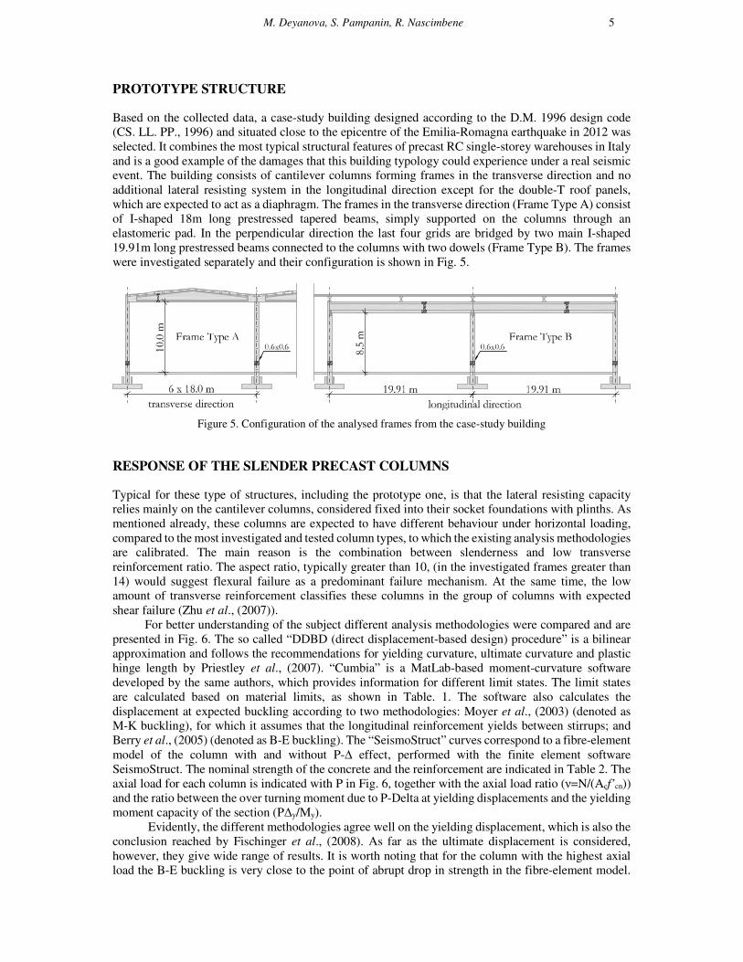
PROTOTYPE STRUCTURE
Based on the collected data, a case-study building designed according to the D.M. 1996 design code
(CS. LL. PP., 1996) and situated close to the epicentre of the Emilia-Romagna earthquake in 2012 was
selected. It combines the most typical structural features of precast RC single-storey warehouses in Italy
and is a good example of the damages that this building typology could experience under a real seismic
event. The building consists of cantilever columns forming frames in the transverse direction and no
additional lateral resisting system in the longitudinal direction except for the double-T roof panels,
which are expected to act as a diaphragm. The frames in the transverse direction (Frame Type A) consist
of I-shaped 18m long prestressed tapered beams, simply supported on the columns through an
elastomeric pad. In the perpendicular direction the last four grids are bridged by two main I-shaped
19.91m long prestressed beams connected to the columns with two dowels (Frame Type B). The frames
were investigated separately and their configuration is shown in Fig. 5.
Figure 5. Configuration of the analysed frames from the case-study building
RESPONSE OF THE SLENDER PRECAST COLUMNS
Typical for these type of structures, including the prototype one, is that the lateral resisting capacity
relies mainly on the cantilever columns, considered fixed into their socket foundations with plinths. As
mentioned already, these columns are expected to have different behaviour under horizontal loading,
compared to the most investigated and tested column types, to which the existing analysis methodologies
are calibrated. The main reason is the combination between slenderness and low transverse
reinforcement ratio. The aspect ratio, typically greater than 10, (in the investigated frames greater than
14) would suggest flexural failure as a predominant failure mechanism. At the same time, the low
amount of transverse reinforcement classifies these columns in the group of columns with expected
shear failure (Zhu et al., (2007)).
For better understanding of the subject different analysis methodologies were compared and are
presented in Fig. 6. The so called “DDBD (direct displacement-based design) procedure” is a bilinear
approximation and follows the recommendations for yielding curvature, ultimate curvature and plastic
hinge length by Priestley et al., (2007). “Cumbia” is a MatLab-based moment-curvature software
developed by the same authors, which provides information for different limit states. The limit states
are calculated based on material limits, as shown in Table. 1. The software also calculates the
displacement at expected buckling according to two methodologies: Moyer et al., (2003) (denoted as
M-K buckling), for which it assumes that the longitudinal reinforcement yields between stirrups; and
Berry et al., (2005) (denoted as B-E buckling). The “SeismoStruct” curves correspond to a fibre-element
model of the column with and without P-∆ effect, performed with the finite element software
SeismoStruct. The nominal strength of the concrete and the reinforcement are indicated in Table 2. The
axial load for each column is indicated with P in Fig. 6, together with the axial load ratio (ν=N/(Acf’cn))
and the ratio between the over turning moment due to P-Delta at yielding displacements and the yielding
moment capacity of the section (PΔy/My).
Evidently, the different methodologies agree well on the yielding displacement, which is also the
conclusion reached by Fischinger et al., (2008). As far as the ultimate displacement is considered,
however, they give wide range of results. It is worth noting that for the column with the highest axial
load the B-E buckling is very close to the point of abrupt drop in strength in the fibre-element model.

6
The ultimate drift of the columns was also evaluated following the approach by Haselton, (2006),
suggested by Fischinger et al., (2008) as the approach that yields better results among all the investigated
ones. The Haselton approach, however, yields unrealistic results for the prototype building, because of
the very low transverse reinforcement ratio for columns ρsh=0.04% compared to that of the structure
tested by Fischinger et al., (2008) - ρsh=0.86%.
Table 1. Material limit states considered by the MatLab algorithm "Cumbia"
after (Priestley, Calvi, & Kowalsky, 2007)
Limit State Concrete Strain Limits Steel Strain Limits
Serviceability 0.004 compression 0.015 tension
Damage control 2/3εcu 0.060 tension
In order to investigate the possibility of shear failure of the columns prior to flexural failure, the
drift at shear failure and the shear capacity were estimated according to Zhu et al., (2007), (Elwood et
al., (2008) and Priestley et al., (1994). All of these methodologies, however, consider columns with
aspect ratios less than 7, much less than the aspect ratio of the columns of the prototype building, thus
the results are either unreasonable, or should be critically treated. For instance, Table. 2 shows that the
method proposed by Zhu et al., (2007) leads to unrealistically large top displacements at shear failure,
due to the very high aspect ratio and at the same time the method by Elwood et al., (2008) yields much
lower displacements due to the very low transverse reinforcement ratio. The latter basically predicts that
these types of columns do not have any ductility, since they are expected to fail in shear almost straight
after yielding. This, however, has not been observed in any of the precast industrial structures
investigated after Emilia-Romagna events. An example is given in Fig. 7, which shows the damages in
one of the columns from the case-study building used for the prototype frames Type A and Type B. The
photographed crack pattern evidently corresponds to a flexure dominated response.
The last six columns in Table.2 calculate the shear capacity according to Priestley et al., (1994),
considering degradation with displacement ductility. The results show shear capacity much higher than
the expected shear demand in the columns, mainly due to the contribution of the high strength concrete.
Serv
iceabili
ty
Dam
age c
ontr
ol
Ultim
ateM
-K b
ucklin
g
B-E
bucklin
g
0
10
20
30
40
50
60
70
80
90
0 0.2 0.4 0.6 0.8 1 1.2
Forc
e [
kN
]
Displacement [m]
Frame Type A, external column
0.600
0.600
Ø24
Serv
iceabili
ty
Dam
age c
ontr
ol
Ultim
ate
M-K
bucklin
g
B-E
bucklin
g
0
10
20
30
40
50
60
70
80
90
0 0.2 0.4 0.6 0.8 1 1.2
Forc
e [
kN
]
Displacement [m]
Frame Type A, internal column
0.600
0.600
Ø20
Serv
iceabili
ty
Dam
age c
ontr
ol
Ultim
ate
M-K
bucklin
g
B-E
bucklin
g
0
10
20
30
40
50
60
70
80
90
0 0.2 0.4 0.6 0.8 1 1.2
Forc
e [
kN
]
Displacement [m]
Frame Type B, left column from Fig. 5
0.600
0.600
Ø20
Serv
iceabili
ty
Dam
age c
ontr
ol
Ultim
ate
M-K
bucklin
g
B-E
bucklin
g
0
10
20
30
40
50
60
70
80
90
0 0.2 0.4 0.6 0.8 1 1.2
Forc
e [
kN
]
Displacement [m]
Frame Type B, mid column from Fig. 5
0.600
0.600
Ø20
Displacement [m]
Cumbia SeismoStruct SeismoStruct with P-Delta DDBD procedure
Figure 6. Force-displacement curves for the top of the columns from the prototype building
P=370kN
ν=0.016
PΔy/My=12.5%
Stirrups ø8/0.2m Stirrups ø8/0.2m
P=665kN
ν=0.028
PΔy/My=26.3%
Stirrups ø8/0.2m
P=1070kN
ν=0.046
PΔy/My=37.1%
Stirrups ø8/0.2m
P=1480kN
ν=0.063
PΔy/My=46.8%

M. Deyanova, S. Pampanin, R. Nascimbene 7
Table 2. Comparison of the drift corresponding to shear failure and of the shear capacity of columns following
three methodologies
Figure 7. Crack pattern on one of the columns from the case-
study building, observed after Emilia-Romagna earthquake
The performance of the column with the highest axial load ratio was also numerically investigated
under the excitation of the second Emilia-Romagna event in May, 2012 from the station closest to the
case-study, direction North (Fig. 8). The non-linear time-history analyses were performed using the
same fibre-element model used for the push-over (Fig. 6 denoted as “SeismoStruct”), again with and
without P-Delta effects. Fig. 9 clearly shows that this type of columns is expected to behave elastically
for very high levels of drift - greater than 2%.
Figure 8. Elastic 5%-damped response spectra of the record from Emilia-Romagna event, May 29, 2012,
Mirandola (MRN) station, north
f'cn= 65 MPa
fyn= 473 MPa
ϕw
[mm]
s
[mm]n ρ'' θ
∆top
[m]θ
∆top
[m]
Vc
[kN]
Vn
[kN]
Vc
[kN]
Vn
[kN]
Frame Type A
external column10 0.36 0.6 370 67 8 200 2 0.0009 0.21 2.08 0.033 0.33 9 226 673 909 232 468
Frame Type A
internal column10 0.36 0.6 665 58 8 200 2 0.0009 0.21 2.06 0.032 0.32 16 226 673 916 232 475
Frame Type B
left column8.5 0.36 0.6 1070 68 8 200 2 0.0009 0.17 1.46 0.032 0.27 30 226 673 930 232 489
Frame Type B
mid column8.5 0.36 0.6 1480 80 8 200 2 0.0009 0.17 1.44 0.031 0.27 42 226 673 942 232 500
c - depth of compression zone Av - are of the transverse reinforcement
Vn - total shear capacity
μ∆ - displacement ductility
Zhu, et al., 2007
Elwood, et al., 2008
Priestley, et al., 1994
ρ'' - transverse reinforcement ratio
θ - drift at shear failure
∆top - displacement of the colunm top
Vp - contribution of the diagonal compression strut
Vs - contribution of the transverse reinforcement
Vc - contribution of the concrete
P - axial load
d - depth of the section
Ag - gross area of the section
L - column length
n - stirrup legs per section
s - spacing of stirrups
ϕw - diameter of stirrups
V - maximum shear demand
μ∆=3 k=0.1
Elwood, et
al., 2008
Zhu, et al.,
2007Vp
[kN]
Vs
[kN]
μ∆=1 k=0.29
Priestley, et al., 1994
ColumnV
[kN]
P
[kN]
d
[m]
Ag
[m2]
L
[m]
Ast
θ � 2.02ρ���0.025s
d� 0.013
L
d�
P
A�f��
θ �3
100� 4ρ�� �
1
40
ν
f ����
1
40
P
A�f′�
V� � k f′�0.8A�V� �d� c
2LPV �
A!f��d′
scot30°
0.00
2.00
4.00
6.00
8.00
10.00
0 1 2 3 4
a [
m/s
2]
Period [s]
0.00
0.20
0.40
0.60
0.80
1.00
1.20
1.40
0 1 2 3 4
v [
m/s
]
Period [s]
0.00
0.10
0.20
0.30
0.40
0 1 2 3 4
d [
m]
Period [s]
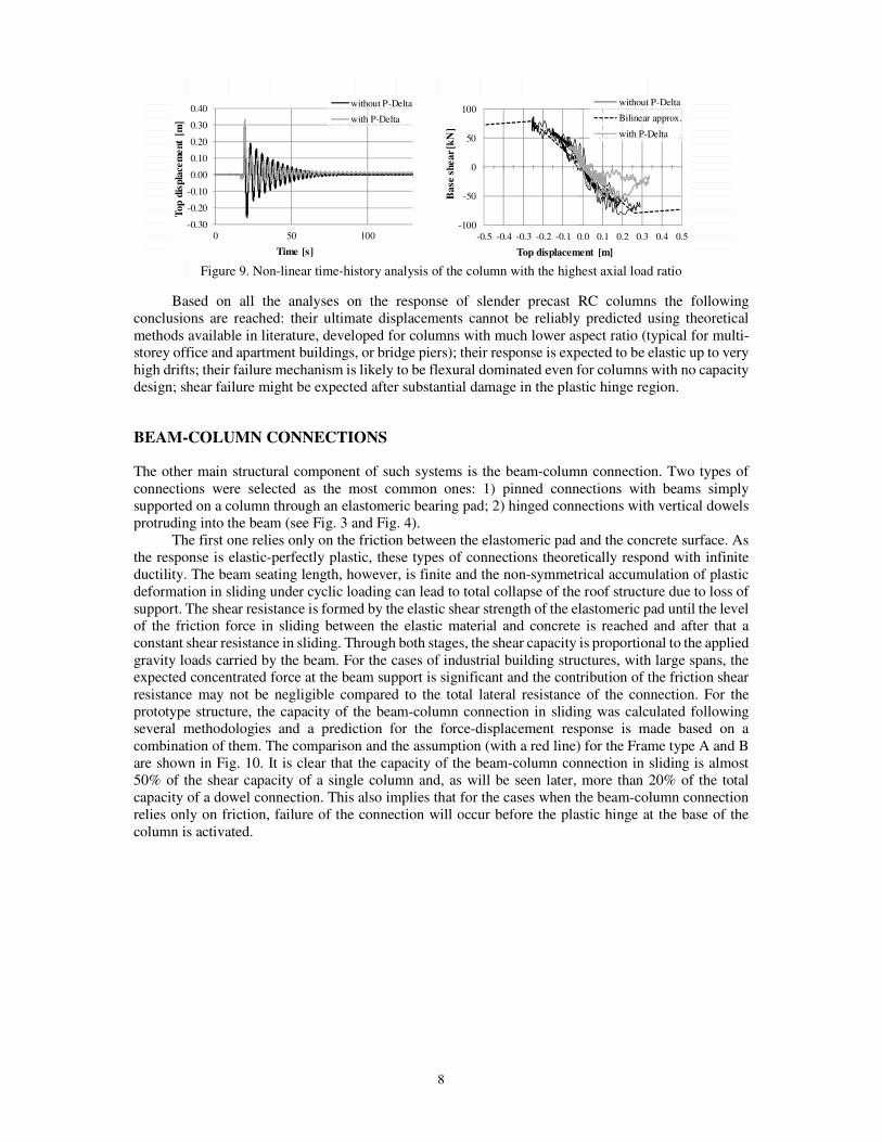
8
Figure 9. Non-linear time-history analysis of the column with the highest axial load ratio
Based on all the analyses on the response of slender precast RC columns the following
conclusions are reached: their ultimate displacements cannot be reliably predicted using theoretical
methods available in literature, developed for columns with much lower aspect ratio (typical for multi-
storey office and apartment buildings, or bridge piers); their response is expected to be elastic up to very
high drifts; their failure mechanism is likely to be flexural dominated even for columns with no capacity
design; shear failure might be expected after substantial damage in the plastic hinge region.
BEAM-COLUMN CONNECTIONS
The other main structural component of such systems is the beam-column connection. Two types of
connections were selected as the most common ones: 1) pinned connections with beams simply
supported on a column through an elastomeric bearing pad; 2) hinged connections with vertical dowels
protruding into the beam (see Fig. 3 and Fig. 4).
The first one relies only on the friction between the elastomeric pad and the concrete surface. As
the response is elastic-perfectly plastic, these types of connections theoretically respond with infinite
ductility. The beam seating length, however, is finite and the non-symmetrical accumulation of plastic
deformation in sliding under cyclic loading can lead to total collapse of the roof structure due to loss of
support. The shear resistance is formed by the elastic shear strength of the elastomeric pad until the level
of the friction force in sliding between the elastic material and concrete is reached and after that a
constant shear resistance in sliding. Through both stages, the shear capacity is proportional to the applied
gravity loads carried by the beam. For the cases of industrial building structures, with large spans, the
expected concentrated force at the beam support is significant and the contribution of the friction shear
resistance may not be negligible compared to the total lateral resistance of the connection. For the
prototype structure, the capacity of the beam-column connection in sliding was calculated following
several methodologies and a prediction for the force-displacement response is made based on a
combination of them. The comparison and the assumption (with a red line) for the Frame type A and B
are shown in Fig. 10. It is clear that the capacity of the beam-column connection in sliding is almost
50% of the shear capacity of a single column and, as will be seen later, more than 20% of the total
capacity of a dowel connection. This also implies that for the cases when the beam-column connection
relies only on friction, failure of the connection will occur before the plastic hinge at the base of the
column is activated.
-0.30
-0.20
-0.10
0.00
0.10
0.20
0.30
0.40
0 50 100
Top d
isp
lace
me
nt
[m]
Time [s]
without P-Delta
with P-Delta
-100
-50
0
50
100
-0.5 -0.4 -0.3 -0.2 -0.1 0.0 0.1 0.2 0.3 0.4 0.5
Ba
se s
hear
[kN
]
Top displacement [m]
without P-Delta
Bilinear approx.
with P-Delta

M. Deyanova, S. Pampanin, R. Nascimbene 9
Figure 10. Horizontal resistance of an elastomeric pad in contact with concrete.
Based on fib, (2008), Magliulo et al., (2011) and PCI design guidelines
The response of the second connection type combines the resistance in sliding with the resistance
of the dowels. A lot of analytical and experimental research has been conducted on the response of the
dowel connections. This includes the SAFECAST research project on mechanical connections in precast
structures under seismic conditions, conducted by a group of European associations of precast structures,
research centres and universities (Toniolo, 2013). As a result, there are many published methodologies
for the analysis of dowel connections. Fig. 11 compares some of them with the experimental results for
quasi-static cyclic tests on several configurations of dowel connections by Psycharis et al., (2012). The
calculations are performed with the geometry and materials corresponding to two of the tests, as shown
above each graph. It should be noted that the different theoretical procedures were calibrated to different
case-studies. The fib bulletine n.43, (2008) for example, considers one-sided dowels with no concrete
edge failure but only dowel failure due to deformations in the plastic hinge and crashing of the
surrounding concrete under to monotonic loading. The same refers to the research performed by
Capozzi, PhD thesis. On the contrary, Tanaka et al., (2011) and Capozzi et al., (2012) considered the
degrading dowel response after edge spalling, again under monotonic loading. Aurelio et al., (2012) and
Fischinger et al., (2013) tested double-sided dowels with no edge splitting. Some of the procedures were
calibrated to experimental set-ups with neoprene pad, whose contribution, however, has not been
explicitly differentiated.
The comparison in Fig. 11 shows that the maximum shear capacity predicted by the theoretical
methods agrees well between each other and with the experimental data. The discrepancies, however,
are significant for the force-displacement response up to failure. The main reason is that the failure of a
dowel connection is a complex combination of the dowel non-linear behaviour, its interaction with the
surrounding concrete and cracking and splitting of the concrete edges. It becomes even more
complicated to predict the predominant failure mode and the sequence of the non-linear stages, when
the dowel connects two concrete elements with different edge distances and/or different concrete
strength. An attempt was made to set up a methodology for the estimation of the dowel response based
on a combination of the compared procedures and two types of failure modes: failure mode dominated
by edge splitting (Fig. 11a), for which the response in “push” and “pull” directions is different after a
certain displacement; and failure dominated by large plastic deformations in the dowels (Fig. 11b), for
which the push-pull response is symmetric. The result of this methodology is presented with the black
lines, together with the exact values that build the curve.
0
10
20
30
40
50
60
70
80
90
0 10 20 30 40 50
Sh
ea
r re
sis
tan
ce [
kN
]
Lateral displacement [mm]
Frame Type A N=285kN
0
10
20
30
40
50
60
70
80
90
0 10 20 30 40 50
Sh
ea
r re
sista
nce
[k
N]
Lateral displacement [mm]
Frame Type B N=420kN
a = 0.24m
b = 0.42m
a = 0.15m
b = 0.42m
Elastic response Magliulo, et al., 2011 PCI fib 43, Fmax fib 43, Fmin Assumed
a
b
a
b

10
Figure 11. a)
Figure 11. b) Comparison between different analytical methodologies for the analysis of dowel connections with
experimental results.
Based on all the aforementioned observations, force-displacement and moment-rotation
relationships were developed for the modelling of the beam-column connection with a finite element
macro-model. The modelling schemes and the capacity curves are shown in Fig. 12 and Fig 13 for Frame
Type A and Frame Type B respectively.
fc'= 35 MPa
fy'= 580 MPa
0
50
100
150
200
250
300
350
0 5 10 15 20 25 30 35
Sh
ea
r re
sist
an
ce F
[k
N]
Lateral displacement ∆ [mm]
Comparison between theoretical and experimental response of dowel connection
dowel shear failure
front splitting
shear capacity
side splitting
∆=
0.1ϕ
F→
Ag
uia
r,2
01
1
∆=
0.2
6ϕ
F→
Ca
po
zzi,
20
12
fro
nt
split
∆≈
10m
m
∆≈
25
mm
pu
ll
F→
Cap
ozz
i,2
012
she
ar
cap
aci
ty
∆≈
30m
m p
ush
400
600
200
100
Ø25
push pull
fc'= 35 MPa
fy'= 580 MPa
156419.7287
0
20
40
60
80
100
120
140
0 5 10 15 20 25 30 35
Sh
ea
r re
sist
an
ce F
[k
N]
Lateral displacement ∆ [mm]
Comparison between theorwtical and experimental response of dowel connection
fib 43, 2008 Tanak, et al., 2011 Capozzi PhD Thesis
Fischinger, et al., 2013 Aguiar, et al., 2011 Capozzi, et al., 2012
Zoubek, et al., 2013 Toniolo, et al., 2013 Psycharis, et al., 2012 - Push
Psycharis, et al., 2013 - Pull Psycharis, et al., 2013 - theoretical Approximation
dowel shear failure
front splitting
shear capacity
side splitting
∆=
0.1ϕ
F→
Agu
iar,
201
1
∆=
0.1ϕ
F→
Ta
na
ka
,2
01
1
∆≈
10m
m
F→
Ca
po
zzi,
201
2
she
ar
cap
aci
ty
100
100
400
600
Ø16push pull

M. Deyanova, S. Pampanin, R. Nascimbene 11
Figure 12. Scheme of the finite-element model of the beam-column connection for Frame Type A and the
corresponding force-displacement relationship for the friction link element
NON-LINEAR TIME-HISTORY ANALYSIS
The non-linear response of the two types of beam-column connection is tested under the excitation of
the same record used for the test of the column dynamic response (see Fig. 8). A finite element model
of the connection is created, by modelling one full length column, half-span beams on both sides of the
connection and link elements as presented in Fig. 12 and Fig. 13. The column is modelled with a fibre
force-based frame element and the beams with elastic frame elements. The values of the masses and the
600
345
345
690
10
190 190
40
355
355
fibre force-based element
elastic frameelement
rigid frameelement
friction linkelement
gap linkelement
X
Z
140 160 140160
-60
-40
-20
0
20
40
60
-300 -200 -100 0 100 200 300
Fo
rce
[k
N]
Displacement [mm]
Z direction
X direction
unseating
-400
-300
-200
-100
0
100
200
300
400
-300 -200 -100 0 100 200 300
Fo
rce
[k
N]
Displacement [mm]
Frame Type B
Z direction
Y direction
unseating
dowel rupture
push pull
Z
X
150 150 150 150
600
750
750
1500
40
150 150
fibre force-based element
friction & rotationallink element
elastic frameelement
gap linkelement
rigid frameelement
-80
-60
-40
-20
0
20
40
60
80
-0.2 -0.15 -0.1 -0.05 0 0.05 0.1 0.15 0.2
Mo
me
nt
[kN
m]
Rotation [rad]
Around X
dowel
failure
beam-column
gap closing
Figure 13. Scheme of the finite-element model of the beam-column connection for Frame Type B and
the corresponding force-displacement and moment-rotation relationships for the link element

12
forces correspond to the tributary area of one beam span. An overview of the finite element model is
presented in Fig. 15.
Some results are presented in Fig. 14. The figure clearly shows that the global response and the
residual displacements are mainly influenced by the relative strength and capacity between the
connection and the adjacent elements. For example, for Frame Type A the base shear strength of the
column is ≈70kN without P-Delta effect and ≈40kN with P-Delta, and the friction capacity of the beam-
column connection is almost 30kN. This explains why when the geometrical non-linearity is not
considered, the relative displacement between the beam and the column top is significant, slightly over
0.12m. When P-Delta effects are considered, there is almost no relative displacement. The same refers
to Frame Type B, for which the strength of the connection is more than twice the shear of the column
that corresponds to the plastic hinge at the base. It should be kept in mind, however, that the numerical
tests performed consider a symmetrical set up, as far as geometry and loads are considered. In reality,
the different capacities of external and internal columns and pounding effects will introduce significant
irregularity and thus change the global response of the building.
Frame Type A Frame Type B
Figure 14. Results from non-linear time-history analyses of the beam-column connections
3.78E-07 0.000389 -2.12E-05 0.000389
4.97E-07 0.000509 -2.11E-05 0.000509
6.36E-07 0.000649 -2.09E-05 0.000649
7.95E-07 0.00081 -2.08E-05 0.00081
9.75E-07 0.000991 -2.06E-05 0.000991
1.18E-06 0.001192 -2.04E-05 0.001192
1.40E-06 0.001414 -2.01E-05 0.001414
1.64E-06 0.001656 -1.99E-05 0.001656
1.90E-06 0.001916 -1.96E-05 0.001916
2.18E-06 0.002194 -1.93E-05 0.002194
2.47E-06 0.002487 -1.90E-05 0.002487
2.78E-06 0.002795 -1.86E-05 0.002795
3.10E-06 0.003115 -1.83E-05 0.003115
3.44E-06 0.003444 -1.79E-05 0.003444
-0.16
-0.14
-0.12
-0.10
-0.08
-0.06
-0.04
-0.02
0.00
0.02
0 20 40 60 80 100
Dis
pla
cem
ent
[m]
Time [s]
Relative horizontal displacement beam-column top
Without P-Delta
With P-Delta
2.97E-07 0.000506 -7.74E-05 0.000506
4.06E-07 0.000685 -7.73E-05 0.000685
5.36E-07 0.000898 -7.72E-05 0.000898
6.89E-07 0.001149 -7.70E-05 0.001149
8.65E-07 0.001438 -7.69E-05 0.001438
1.07E-06 0.001767 -7.67E-05 0.001767
1.29E-06 0.002136 -7.64E-05 0.002136
1.54E-06 0.002545 -7.62E-05 0.002545
1.82E-06 0.002995 -7.59E-05 0.002995
2.12E-06 0.003485 -7.56E-05 0.003485
2.45E-06 0.004012 -7.53E-05 0.004012
2.79E-06 0.004577 -7.49E-05 0.004577
3.16E-06 0.005177 -7.45E-05 0.005177
3.55E-06 0.005809 -7.41E-05 0.005809
3.96E-06 0.00647 -7.37E-05 0.00647
-0.16
-0.14
-0.12
-0.10
-0.08
-0.06
-0.04
-0.02
0.00
0.02
0 20 40 60 80 100
Dis
pla
cem
ent
[m]
Time [s]
Relative horizontal displacement beam-column top
Without P-Delta
With P-Delta
0.25 2.16E-05
0.275 2.16E-05
0.3 2.16E-05
0.325 2.16E-05
0.35 2.15E-05
0.375 2.15E-05
0.4 2.15E-05
0.425 2.15E-05
0.45 2.15E-05
0.475 2.15E-05
0.5 2.14E-05
0.525 2.14E-05
0.55 2.14E-05
0.575 2.14E-05
-80
-60
-40
-20
0
20
40
60
80
-0.4 -0.2 0.0 0.2 0.4
Base
shear
[kN
]
Horizontal displacement [m]
Column top
Without P-Delta
With P-Delta
0.225 7.78E-05 3.00E-07 2.29E-05
0.25 7.78E-05 4.14E-07 -0.04515
0.275 7.78E-05 5.59E-07 0.005309
0.3 7.77E-05 7.08E-07 0.057604
0.325 7.77E-05 8.86E-07 -0.01977
0.35 7.77E-05 1.11E-06 0.012216
0.375 7.77E-05 1.35E-06 -0.00146
0.4 7.77E-05 1.60E-06 0.012865
0.425 7.77E-05 1.88E-06 -3.67E-03
0.45 7.77E-05 2.21E-06 -0.00024
0.475 7.77E-05 2.54E-06 0.001763
0.5 7.77E-05 2.90E-06 0.007163
0.525 7.77E-05 3.29E-06 0.004069
0.55 7.77E-05 3.69E-06 0.008807
0.575 7.77E-05 4.13E-06
-150
-100
-50
0
50
100
150
-0.4 -0.2 0.0 0.2 0.4
Base s
hear
[kN
]
Horizontal displacement [m]
Column top
Without P-Delta
With P-Delta
-2.13E-05 5.12E-05
-2.12E-05 0.001583
-2.11E-05 -0.00375
-2.09E-05 0.009592
-2.07E-05 -0.0005
-2.05E-05 0.00573
-2.03E-05 0.003241
-2.00E-05 0.001459
-1.98E-05 -7.69E-05
-1.95E-05 0.001241
-1.92E-05 0.002456
-1.88E-05 0.001649
-1.85E-05 0.002974
-1.81E-05 0.002087
-1.77E-05 0.002899
-80
-60
-40
-20
0
20
40
60
80
-0.4 -0.2 0.0 0.2 0.4 0.6
Base
shear
[kN
]
Horizontal displacement [m]
Beam at the connection
Without P-Delta
With P-Delta
-7.75E-05 2.29E-05
-7.73E-05 -0.04515
-7.72E-05 0.005309
-7.70E-05 0.057604
-7.68E-05 -0.01977
-7.66E-05 0.012216
-7.64E-05 -0.00146
-7.61E-05 0.012865
-7.58E-05 -3.67E-03
-7.55E-05 -0.00024
-7.52E-05 0.001763
-7.48E-05 0.007163
-7.44E-05 0.004069
-7.40E-05 0.008807
-7.36E-05 0.00287
-150
-100
-50
0
50
100
150
-0.4 -0.2 0.0 0.2 0.4
Ba
se s
hea
r [k
N]
Horizontal displacement [m]
Beam at the connection
Without P-Delta
With P-Delta

M. Deyanova, S. Pampanin, R. Nascimbene 13
Figure 15. Overview of the finite element model created in SeismoStruct for the analysis of the beam-column
connections
CONCLUSIONS AND FUTURE RESEARCH
This paper presents results of an investigation into the non-linear behaviour under seismic loading of
two types of pinned/hinged beam-column connections, typical of precast concrete industrial buildings
in Italy, together with the response of the slender columns. The following conclusions are reached:
o The beam-column connections of typical types of existing precast concrete structures do not
necessarily perform adequately under seismic loading. This is true even for those designed in
very recent times;
o The theoretical methods available in the literature and developed for columns with lower
aspect ratio cannot reliably predict the ultimate displacement of slender columns with aspect
ratio greater than 7;
o The response of slender columns like those investigated here can be expected to remain in
the elastic range for high levels of drift, up to 2%;
o The failure mechanism of the columns in this type of buildings is dominated by flexure even
for columns with no capacity design and low transverse reinforcement ratio;
o The existing theoretical approaches for the design of dowel connections agree well with each
other and with experimental results in terms of maximum design strength but not in terms of
force-displacement response up to failure. Based on them, in the present study a methodology
for the prediction of the cyclic response of dowel beam-column connections is proposed;
o The global response of the building is governed by the relative strength between the
connection and the column;
o If the beam-column connection is loaded symmetrically, it is expected to behave well under
seismic excitation. Different sources of irregularities, however, like different strength
between external and internal columns and pounding effects can significantly influence the
response of the connection. Further investigation is needed for the evaluation of these
phenomena;
o The influence of the rotation and uplift of the plinth foundations needs to be additionally
investigated;
o The conclusions presented in the present study can also be useful for the development of
adequate retrofit and design techniques.

14
REFERENCES
Aurelio, E., Bellucio, E. K., & Khalil El Debs, M. (2012). Behaviour of grouted dowels used in precast concrete
structures. Structural Concrete . Belleri, A., Brunesi, E., Nascimbene, R., Pagani, M., & Riva, P. (2014). Seismic performance of precast
industrial facilities following major earthquakes in the Italian territory. Journal of Performance of
Constructed Facilities, 1943-5509.
Belleri, A., Torquati, M., & Riva, P. (2012). Displacement based assessment for precast concrete structures:
application to a three story plane frame. 12 WCEE Lisboa.
Bellotti, D., Bolognini, D., & Nascimbene, R. (2009). Response of Traditional RC Precast Structures under
cyclic loading. Environmental Semeiotics, 2, 63-79.
Berry, P. B., & Eberhard, M. O. (2005). Partical Performance Model for Bar Buckling. ASCE Journal of
Structural Engineering, 131.
Bournas, D., Negro, P., Molina, F. J., Bernard, V., & Magonette, G. (2012). Pseudodynamic Testing of the
SAFECATS 3-Storey Precast Concrete Building. JRC Technical reports.
Boys, A., Bull, D. K., & Pampanin, S. (2008). Seismic Performance Assessment of Inadequately Detailed
Reinforced Concrete Columns. NZSEE Conference.
CAPOZZI, V. (n.d.). Comportamento sismico dei collegamenti nelle struture prefabbricate. Tesi di dottorato.
Capozzi, V., Magliulo, G., & Manfredi, G. (2012). Nonlinear Mechanical Model of Seismic Behaviour of Beam-
Column Pin Connections. 15 WCEE, Lisboa.
Contegni, M. M., Palermo, A., & Toniolo, G. (2008). Strutture Prefabbricate: Schedario di Edifici Prefabbricati
in C.A. DPS/RELUIS.
CS.LL.PP. (1996, Gennaio 16). Norme techniche per le costruzioni in zone sismiche. Gazzetta Ufficiale della
Repubblica(29).
Elwood, K. J., & Moehle, J. P. (2008). Dynamic Shear and Axial-Load Failure of Reinforced Concrete Columns.
ASCE - J. Struct. Eng., 134, 1189-1198.
fib bulletin n.43. (2008). Structural connections for precast concrete. International Federation for Structural
Concrete.
Fischinger, M., Kramar, M., & Isakovic, T. (2008). Cyclic response of slender RC columns typical of precast
industrial buildings. Bull Earthquake Eng, 6, 519-534.
Fischinger, M., Zoubek, B., & Isakovic, T. (2013). Seismic behaviour of the beam-to-column dowel connectons:
macro modelling. Kos Island, Greece: COMPDYN.
Haselton, C. B. (2006). Assessing seismic collapse safety of modern reinforced concrete moment frame
buildings. Dissertation, Stanford University.
Kremmyda, G., Fahjan, Y., & Psycharis, I. (2013). Analytical prediciton of the shear resistance of precast RC
pinned beam-to-column connections. COMPDYN.
Magliulo, G., Capozzi, V., Fabbrocino, G., & Manfredi, G. (2011). Neoprene-concrete frictioin relationships for
seismic assessment of existing precast builidngs. Engineering Structures(33), 532-538.
Moyer, M. J., & Kowalsky, M. J. (2003). Influence of Tension Strain on Buckling of Reinforcement in Concrete
Columns. ACI Structural Journal, 100.
Priestley, M. J., Calvi, G. M., & Kowalsky, M. J. (2007). Displacement - Based Seismic Design of Structures.
Pavia, Italy: IUSS Press.
Priestley, M., Verma, R., & Xiao, Y. (1994). Seismic Shear Strength of Reinforced Concrete Columns. ASCE -
J. Struct. Eng., 120, 2310 - 2329.
Psycharis, L. N., & Mouzakis, H. P. (2012). Shear resistance of pinned connections of precast members to
monotonic and cyclic loading. Engineering Structures, 413-327.
Tanaka, Y., & Murakoshi, J. (2011). Reexamination of Dowel Behavior of Steel Bars Embedded in Concrete.
ACI Structural Journal.
Toniolo, G. (2013). SAFECAST project: European research on seismic behaviour of the connections of precast
structures. COMPDYN.
Zhu, L., Elwood, K. J., & Haukaas, T. (2007). Classification and seismic safety evaluation of existing reinforced
concrete columns. ASCE - J. Struct. Eng., 133, 1316 - 1330.
Zoubek, B., Isakovic, T., Fahjan, Y., & Fischinger, M. (2013). Cyclic failure analysis of the beam-to-column
dowel connections in precast industrial buildings. Engineering Structures, 179-191.