associate professor university of belgrade a new
TRANSCRIPT
© Faculty of Mechanical Engineering, Belgrade. All rights reserved FME Transactions (2017) 45, 149-158 149
Received: January 2016, Accepted: March 2016 Correspondence to: dr Sasa Zivanovic Faculty of Mechanical Engineering, Kraljice Marije 16, 11120 Belgrade 35, Serbia E-mail: [email protected] doi:10.5937/fmet1701149Z
Saša T. Živanović Associate professor
University of Belgrade Faculty of Mechanical Engineering
Goran V. Vasilić PhD Student
University of Belgrade Faculty of Mechanical Engineering
A New CNC Programming Method Using STEP-NC Protocol
A new programmnig method of CNC Machine tools, which is developing
as an alternative to G code, is AP238 protocol or STEP-NC, according to
ISO 10303 standard. In this paper, a comparation between classical (G
code) and new way of programming (STEP-NC ) is given. A structure of
ecquipment needed for new programming metod, program structure and
current scenario for imlementation of STEP-NC are shown. Verification of
the above scenarios using the STEP-NC, is realized through three examples.
Keywords: STEP-NC, NC programming, CNC, CAD/CAM
1. INTRODUCTION
For more than half a century machine tool programming is based on the G code, (ISO 6983 [1]). Further developments, however, are now being significantly limited by the current programming language (ISO6983) that has been always supporting NC manufacture. Machine tools have evolved from simple machines with controllers that had no memory, driven by punched tape to today’s highly sophisticated Computer Numerically Controlled (CNC) machine tools [2].
Machine tools have changed radically, but the programming language has basically remained the same with G code programming. Machine tool programming using G code is characterized by a low level of information content. This low level information describes elementary actions and tools moves, strongly reducing possibilities at the CNC level. It also breaks the CAD→CAM→CNC numerical chain, and gathering feed back from the shop floor is hardly possible [3]. It is necessary to prepare the tool path for each type of CNC machine tools individually using appropriate postprocessor. It requires large number of different postprocessor for each type of machine tool. Therefore, the classical programs for CNC machine tools (G-code) do not include any useful information about the product, such as data about the geometric primitives of the model, tolerances, material properties, setting up fixture, and other information created during the design and planning of manufacturing technology. All this information will disappear when converting tool path in G code. Usually it is expressed through the following shortcomings: • lose a significant part of data between CAM and
machine tool control unit, • breaks the CAD-CAM-CNC numerical chain,
without feedback from the shop floor, • information flow is one-way, from CAM to a CNC
machine tool. Today a new standard, known as STEP-NC (Standard
for Product Model Data Exchange for Numerical Control), is being used as the basis for development of the next generation of CNC controller. This standard is ISO 14649[4] and ISO 10303 AP 238[5]. The STEP-NC AP238 standard is the result of a more fifteen years international effort to replace G code (ISO 6983 standard) with a modern associative language that connects the CAD design data used to determine the machining requirements for an operation with the CAM process data that solves those requirements [6].
In the field of machine tool programming an open challenge is the new programming method using standard known as STEP-NC. The development of new method of programming is a start, but it is still an unfinished work [7-11].
STEP-NC is a new interface that has been developed for exchange of information between CAD/CAM systems and CNC controllers. Its object oriented design and the use of data elements of the widely disseminated STEP standard support comprehensive bi-directional data exchange whilst using common databases [12].
The STEP-NC provides new opportunities to support high level information from design to CNC controller. It allows bi-directional data flow between CAD/CAM and CNC without any information loose. STEP-NC does not describe the tool movements for specific CNC machine tool as G code (Figure 1) does, but it provides a feature based data model (Figure 2). A STEP-NC file is not machine tool specific and can be used on various machine tool controllers [3].
Figure 1 and Figure 2 show the comparison of ISO 6983 (G-code) and ISO 14649 (STEP-NC). STEP-NC describes ‘‘WHAT’’ to make, while G-code describes ‘‘HOW’’ to make [13].
If we analyze the current state of programming machines using G code [12,13], it could be said: � The language focuses on programming the path of
the cutter centre location (CL) with respect to the machine axes;
� Vendors usually supplement the language with extensions, and the CNC programs are not exchangeable;
� The language supports one-way information flow from design to manufacturing, the changes in the shop floor cannot be directly fed back to the designer;

150 ▪ VOL. 45, No 1, 2017 FME Transactions
� There is limited control of program execution and it is difficult to change the program in the workshop;
� The CAD data are not used directly on the machine; � Required use of a postprocessor for each different
machine.
Figure 1. Current G-code programming
Figure 2. New CNC programming method using STEP-NC
There was a time when you needed a machine programmed by the project workpiece geometry (CAD) without conversion in preparation for machine operation.
Benefits of using STEP-NC have been recognized [12,13]: � The STEP-NC data interface would be a neutral
data description: CAM system independent, machine controller independent and machine tool independent.
� Bi-directional information flow. Modification at the shop-floor can be saved and feedback to the designer.
� Machine tools are safer and more adaptable because STEP-NC is independent from the machine tool vendor.
� Higher quality of information on the shop floor. The CAD data are used directly on the machine;
� Post-processors will be eliminated because the interface does not require machine-specific information.
� XML files can be used for information transfer and enable Web based manufacturing or e-manufacturing
2. OVERVIEW OF STEP-NC STANDARDS
Several research projects, industries and academic institutes all around the world have been developing STEP-NC [14-19] .The first ISO 14649 publications are: (i) ISO 14649-1:2003 Overview and fundamental principles; (ii) ISO 14649-10:2003 General process data, (iii) ISO 14649-11:2003 Process data for milling.
The global research in the areas of STEP-NC has been primarily coordinated under a single IMS (Intelligent Manufacturing System) project that effectively entails an international package of actions. Partners from four regions participate in the project: EU, Korea, Switzerland and USA. They covered the manufacturers, the users and academic institutions. The regional coordinators are Siemens (EU), CADCAMation (Switzerland), STEP Tools (USA) and ERC-ACI (Korea). The most active research activities are found among the partners in the EU regions [18,19], USA[14-17], Korea [3,8], and New Zealand [2,9,13,20-22].
There are two different ISO subcommittees working on the STEP-NC standard with two different focuses. ISO TC 184/SC1 is working on the ISO 14649 (ARM model) whereas ISO TC 184/SC4 is working on the STEP AP-238 (AIM model). The main difference between these two models is the degree to which they use the STEP representation methods and technical architecture [2]. Table 1 compares these two models.
ISO 14649 and ISO 10303-238 can be viewed as two different implementation methods of the STEP-NC standard. The ISO 14649 standard is more likely to be used in an environment in which CAM systems have exact information from the shop floor, whereas STEP AP-238, as a part of the STEP standard, is more suitable for a complete design and manufacturing integration.
The ISO 14649 standard has no mechanism to incorporate other types of STEP data, hence making bi-

FME Transactions VOL. 45, No 1, 2017 ▪ 151
directional data flow between design and manufacturing more difficult. Unlike ISO 14649, STEP AP-238 encompasses all the information from STEP AP-203 and AP-224 plus an interpreted model mapped from ISO 14649. Therefore, bi-directional data exchange is enabled.
Table 1. Comparisons between ARM and AIM model [2]
Comparison criteria ↓
ISO 14649
(ARM) model ISO 10303-238 (AIM) model
Storage needed ~10 times less than AIM
~10 times more than ARM
Programming Easy More complex
Human readable
Difficult Almost impossible
Compatibilities with STEP
Partly compliant Fully compliant
Data consistency
Original design information is abandoned
Original design information is preserved
Both models represent the data model information to program intelligent CNC controllers, but the AIM is fully STEP compliant, whereas the ARM contains the information required to program a CNC machine. The ARM is to be used in an environment in which CAM systems have exact information from the shop-floor, whereas AIM is more suitable for a complete design and manufacturing integration [2, 23].
STEP-NC AIM file includes the information about the design model itself, the stock, its manufacturing features, the tool/fixture requirements, the manufacturing process sequence, etc. It is self-documenting and allows complete safety checking. This type of information can be described as ‘‘what-to-do’’ information, meaning that only manufacturing tasks are described, but not the way(s) of completing them. This type of ‘‘what-to-do’’ information is then fed to a STEP-NC controller to generate so-called ‘‘how-to-do’’ information, which may still be documented in an ISO 14649 file, i.e. an ARM file [20].
3. STEP-NC DATA MODEL AND DATA FORMAT The method of programming using the STEP-NC is the object-oriented view of programming in terms of manufacturing features, instead of direct coding of sequences of axis motions and tool functions as per defined in ISO 6983 [13,24].
The fundamental principle of the new data model is the programming in terms of manufacturing features (hole, pocket, etc.), instead of direct coding of sequences of axis motions and tool functions. The combination of manufacturing features and technological information is referred to as a “working step”. Working steps represent the essential building blocks of the machining process. Each working step describes a single manufacturing operation using one tool and one strategy [15].
However, classical programming is still there and object-oriented programming has not been introduced to the full extent. These two methods exist simultaneously as illustrated in Figures 1 and 2.
A part program is described in a Physical File Format according to the ISO 10303 Part 21. Data structure of the STEP-NC file is shown in Figure 3.
Figure 3. Data structure of the object oriented Data model of a STEP-NC file [13,15,20]
The first section of the part program is the header section marked by the keyword “HEADER”. This header contains some general information and comments about the part program, such as filename, author, date and organization. The second and main section of the program file is the data section marked by the keyword “DATA”. This section contains all information about manufacturing tasks and geometries. The data are divided into three significant parts, (A) workplan and executables; (B) technology description and (C) geometry description. CNC machines are therefore provided with rich information for part manufacture. CNC machine tools are also made responsible for translating information defined by STEP-NC such as Working steps to axis motion and tool operation.
Part 21 and Part 28 are the two common implementation methods for defined STEP data. The Part 21 file format is currently the most popular implementation method. Now Part 28 files in format XML are more and more used. The part of STEP-NC file described in a Physical File Format according to the ISO 10303- 21 is shown in Figure 4a and the part of STEP-NC file described in a Physical File Format according to the ISO 10303-28 (XML format), is shown in Figure 4b.
The main difference between these two formats shown in Table 2.
Table 2. STEP Part 21 compared with early binding approach of STEP Part 28 [2]
Format Comparison criteria
STEP Part 21 Early binding
approach of STEP Part 28
Abilities of representing
EXPRESS instances Yes Yes
Extensibilities Weak Strong Storage required Less More
Structure Cross-link based Hierarchy structured
Data repetition No Yes Human interpretable Partly Completely
Difficulty of interpreting
Hard Easy
Exchange via Web pages
Can only be done via an individual
physical file
Can exchange any part of the
document in its hierarchy structure

152 ▪ VOL. 45, No 1, 2017 FME Transactions
a) ISO-10303-21; HEADER; FILE_DESCRIPTION(('ISO 14649-11 EXAMPLE 1', 'SIMPLE PROGRAM WITH A PLANAR_FACE, A POCKET, AND A ROUND_HOLE'), '1'); FILE_NAME('EXAMPLE1.STP', '2002-02-02', ('YONG TAK HYUN','JOCHEN WOLF'), ('WZL, RWTH-AACHEN'), '$', 'ISO 14649', '$'); FILE_SCHEMA(('MACHINING_SCHEMA','MILLING_SCHEMA')); ENDSEC; DATA; #1= PROJECT('EXECUTE EXAMPLE1',#2,(#4),$,$,$); #2= WORKPLAN('MAIN WORKPLAN',(#10,#11,#12,#13,#14),$,#8,$); #4= WORKPIECE('SIMPLE WORKPIECE',#6,0.010,$,$,$,(#66,#67,#68,#69)); #6= MATERIAL('ST-50','STEEL',(#7)); #7= DESCRIPTIVE_PARAMETER('E=200000N/M2','mild'); #8= SETUP('SETUP1',#71,#62,(#9)); #9= WORKPIECE_SETUP(#4,#74,$,$,()); #10= MACHINING_WORKINGSTEP('WS FINISH PLANAR FACE1',#62,#16,#19,$); #11= MACHINING_WORKINGSTEP('WS DRILL HOLE1',#62,#17,#20,$); ... #125= CUTTING_COMPONENT(80.000,$,$,$,$); /* #125= CUTTING_COMPONENT(80.000,$,$,$); ORIGINAL BAD */ #126= CUTTING_COMPONENT(90.000,$,$,$,$); /* #126= CUTTING_COMPONENT(90.000,$,$,$); ORIGINAL BAD */ #127= CUTTING_COMPONENT(100.000,$,$,$,$); /* #127= CUTTING_COMPONENT(100.000,$,$,$); ORIGINAL BAD */ ENDSEC; END-ISO-10303-21;
b) <?xml version="1.0" ?> <iso_10303_28_terse xmlns="urn:oid:1.0.10303.238.1.0.1" xmlns:exp="urn:oid:1.0.10303.28.2.1.1" xmlns:xsi="http://www.w3.org/2001/XMLSchema-instance" schema="integrated_cnc_schema"> <exp:header> <exp:name>7 inch mm CDS</exp:name> <exp:time_stamp>2006-10-24T08:17:10-04:00</exp:time_stamp> <exp:author>STEP-NC Maker 3.0</exp:author> <exp:preprocessor_version>ST-DEVELOPER v11</exp:preprocessor_version> <exp:originating_system>Various</exp:originating_system> </exp:header> <!-- *********************************************** * Application object: PROJECT (id10) * ITS_WORKPIECES [*]: id10, id11, id2284 * ITS_ID: id10, id12, id13, ['New Project'] * MAIN_WORKPLAN: id10, id14, id15, id11187 ... <Machining_process_sequence_relationship id="id11223" Name="" Description="" Relating_method="id11187" Related_method="id10950" Sequence_position="36"/> <Machining_process_sequence_relationship id="id11224" Name="" Description="" Relating_method="id11187" Related_method="id10956" Sequence_position="37"/> ... <!-- *********************************************** * END OF APPLICATION OBJECT DESCRIPTIONS --> <Application_protocol_definition id="id11226" Status="international standard" Application_interpreted_model_schema_name="integrated_cnc_schema" Application_protocol_year="2006" Application="id17"/> </iso_10303_28_terse>
Figure 4. The part of STEP-NC programs in formats p21 and p28

FME Transactions VOL. 45, No 1, 2017 ▪ 153
As shown in Table 2, Part 28 has many advantages over Part 21. However, the Part 21 syntax predates Part 28 by a number of years and now most STEP-compliant applications and developing tools are based on the Part 21 definition. Part 21 files have a stronger presence in CAD systems [2].
4. SCENARIOS FOR NEW METHOD PROGRAMMING
BASED ON STEP-NC
At this moment this method of programming can not be completely used, because the resources for that in the development are owned by several research centers [24]. So here two possible scenarios (SC1, SC2) [25] will be considered, Figure 5 - the indirect application of this method of programming on existing machines and the available software. These scenarios are:
• Scenario SC1 - use the original STEP-NC program, postprocessing into G code and execute on the machine tool, and
• Scenario SC2 - model part in the CAD/CAM system, and then in the STEP format, import a reference model, workpiece, tools and tool path (CL file) in software STEP-NC Machine [14], where the saved STEP-NC program. For now, the first scenario is realistic and feasible in
two ways. The first way is to use a CL file, which is specifically imported into the available CAD/CAM system and its postprocessing for the selected machine tool. CAD system takes reference model and workpiece in STEP format and CL File. Verification of material removal is done in a CAD/CAM system in the module (NC Check). CAD/CAM system uses configured postprocessor to generate G code for the available machine tools. G code is executed on the available machine tools.
The second way uses an internal application to the direct export of STEP-NC program in G code from the available control units, offered by STEP-NC Machine (Fanuc, Siemens, Okuma, Haas,...). All machines, in our laboratory, use the G-code as for Fanuc CNC systems, and for all available machines we can directly convert the STEP-NC program in G code.
As a classical CAD/CAM system Pro/Engineer Wildfire 4, or PTC Creo 2 was used. For interpretation of original STEP-NC file used the software STEP-NC Machine. Original STEP-NC program is downloaded from the website for the international promotion of STEP-NC [14]. For the second scenario SC2 the part is modelled [19] in the CAD/CAM system. Afterwards reference model, workpiece, and tools are converted into the STEP format, and together with tool path (CL file) are imported into the software STEP-NC Machine. In this software the STEP-NC program is saved in the format of STEP-NC AP238 (*. stpnc, * .238).
5. MACHINING TEST
Verification of the above scenarios using the STEP-NC, is realized through three examples. For scenario SC1 two examples are shown. The first example refers to the machining benchmark workpiece based on the original
STEP-NC program according to ISO 14649-11 (ARM model). The second example refers to the machining test workpiece NAS 979 based on the original STEP-NC program according to ISO 10303 AP238 (AIM model). The third example has been done for scenario SC2. For the experiments we used the resources of Laboratory from University of Belgrade, Faculty of Mechanical Engineering: Horizontal machining center LOLA HMC 500, Industrial prototype of 3 axis vertical milling machine with parallel kinematics LOLA pn101_4 V2 [26] and Mini-laboratory and desktop 3-Axis parallel kinematic milling machine, pn101_st V1.5 [27].
The example 1 on ISO14649 part 11 is used for the first test, shown in Figure 6. There are five machining working steps in the original file. They are for milling the top surface of the workpiece; drilling and reaming the hole; and rough and finish milling the pocket.
NIST has built two STEP-NC interpreters [28] for milling operations, one using STEP-NC AIM (ISO10303-AP238), and the other using STEP-NC ARM (ISO14649-10-11). The system outputs Canonical Machining Commands (CMCs) [22].
Original STEP-NC program according to ISO 14649-11 is translated using STEP-NC interpreter in Canonical Machining Commands (CMCs), then these CMCs are translated into G code and then machining workpiece on the industrial prototype of 3 axis vertical milling machine with parallel kinematics LOLA pn101_4 V2 is carried out. The same workpiece, only scaled in the ratio of 1:5 is machined on the mini laboratory and desktop 3-axis PKMM - pn101_st V1.5. The result of tool path generation of example and machining result of the first example is shown in Figure 6.
The second example refers to the machining test workpiece NAS979 (circle/diamond/square test). According to the scenario SC1, original STEP-NC program (AIM model) is translated into the G code and then it was machined on the 3 axis vertical milling machine with parallel kinematics LOLA pn101_4 V2. Previously necessary simulations were made (in STEP-NC Machine software) for the reconstruction of machining technology for a test NAS 979 [29].
File format STEP-NC for part NAS979 is directly translated into Fanuc G code using the Export option of software STEP-NC Machine, Figure 7. As a part of the promotion activities on the STEP-NC, the test workpiece NAS979 (circle/diamond/square test) is machined during presentation in Orlando (Florida, USA) [30].
Scenario SC2 that involves importing geometry elements of the reference model (Figure 8), workpiece, tool and tool path from common CAD/CAM system into STEP-NC Machine software, is shown in Figure 9. For scenario SC2 CAD/CAM system Pro /Engineer Wildfire 4 was used. The scenario SC2 is performed as follows:
� for a given part (Figure 8) CAD models of reference model, workpiece and tool in the CAD/CAM system were created. This part was selected as an example from the website of the EU activities in the field of application of STEP-NC [19];

154 ▪ VOL. 45, No 1, 2017 FME Transactions
Figure 5. Scenarios for the application of STEP-NC programming
Figure 6. The result of machining - example 1
� planned and implemented technology for machining, which includes roughing and finishing;
� tool path CL file (*. ncl) was generated; � toolpath and material removal simulations (NC
Check) were performed in order to verify program; � we prepared the input for software STEP-NC
Machine, by exporting reference model, workpiece and tool from Pro/E in STEP format;
� We have loaded in software STEP-NC Machine the reference model, model of the workpiece, model of tool in STEP format, and Cutter Location File (CLF);
� program was saved in the format of STEP-NC AP238 (*. stpnc, * .238);
� program was tested by simulations on different machines available in the software STEP-NC Machine;
� for the part presented in Figure 8, program for machining was directly translated into Fanuc G code using the Export option of software STEP-NC Machine;
� part was machined on the machining center LOLA HMC500.
The machining result of the example, from Figure 8, on horizontal machining centre LOLA HMC500, is shown in Figure 9.
Verification of the above scenarios using the STEP-NC, is realized through three examples. The first example refers to the machining two benchmark workpieces based on the original STEP-NC program, Figure 6 and based on the test workpiece NAS979, Figure 7. The second example has been done for scenario SC2, Figure 9.
These experiments have confirmed that it is possible to realise scenarios for programming CNC machine tools based on STEP-NC programs.

FME Transactions VOL. 45, No 1, 2017 ▪ 155
Figure 7. First Scenario (SC1) - machining NAS979
Figure 8. Reference model for second scenario (SC2)

156 ▪ VOL. 45, No 1, 2017 FME Transactions
Figure 9. Second Scenario (SC2)
FME Transactions VOL. 45, No 1, 2017 ▪ 157
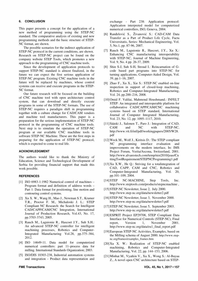
6. CONCLUSION This paper presents a concept for the application of a new method of programming using the STEP-NC standard. The comparative analysis of existing and new programming methods and the basic structure of STEP-NC format, are shown.
The possible scenarios for the indirect application of STEP-NC protocol in the current conditions, are shown. Research on STEP-NC project can be found on the company website STEP Tools, which promotes a new approach to the programming of CNC machine tools.
Since the development of application protocols to support STEP-NC standard is almost finalized, in the future we can expect the first serious application of STEP-NC program. Existing CNC machine tools in the future will be replaced by machines, whose control systems can receive and execute programs in the STEP-NC format.
Our future research will be focused on the building of CNC machine tool with open architecture control system, that can download and directly execute programs in some of the STEP-NC formats. The use of STEP-NC requires a paradigm shift in programming together with a culture change for CAD/CAM vendors and machine tool manufacturers. This paper is a preparation for the serious implementation of STEP-NC protocol in the programming of CNC machine tools. Next step is to simulate the operation of STEP-NC program at our available CNC machihne tools in software STEP-NC Machine. These are the first steps in preparing for the application of STEP-NC protocol, which is expected to come to real life.
ACKNOWLEDGMENT
The authors would like to thank the Ministry of Education, Science and Technological Development of Serbia for providing financial support that made this work possible.
REFERENCES
[1] ISO 6983-1:1982 Numerical control of machines – Program format and definition of address words – Part 1: Data format for positioning, line motion and contouring control systems.
[2] Xu X. W., Wang H., Mao J., Newman S.T., Kramer T.R., Proctor F. M., Michaloski J. L.: STEP Compliant NC Research: the Search for Intelligent CAD/CAPP/CAM/CNC Integration, International Journal of Production Research, Vol.43, No. 17, pp.3703-3743, 2005.
[3] Rauch M., Laguionie R., Hascoet J.Y., Suh S.H.: An advanced STEP-NC controller for intelligent machining processes, Robotics and Computer-Integrated Manufacturing Vol.28, pp.375–384, 2012.
[4] ISO 14649-11. Data model for computerized numerical controllers: part 11–process data for milling. International Standards Organization; 2003.
[5] ISO/DIS 10303-238, Industrial automation systems and integration - Product data representation and
exchange - Part 238: Application protocol: Application interpreted model for computerized numerical controllers, ISO, Geneva, 2004.
[6] Ranđelović S., Živanović S.: CAD-CAM Data Transfer as a Part of Product Life Cycle, Facta Universitatis, Series: Mechanical Engineering, Vol. 5, No.1, pp. 87-96, 2007.
[7] Rauch M., Laguionie R., Hascoet, J.Y., Xu X.: Enhancing CNC manufacturing interoperability with STEP-NC, Journal of Machine Engineering, Vol. 9, No. 4 pp. 26-37, 2009.
[8] Shin S-J, Suh S-H, Stroud I.: Reincarnation of G-code based part programs into STEP-NC for turning applications, Computer-Aided Design, Vol. 39, pp.1–16, 2007.
[9] Zhao F., Xu X., Xie S.: STEP-NC enabled on-line inspection in support of closed-loop machining, Robotics and Computer-Integrated Manufacturing, Vol. 24, pp.200–216, 2008.
[10] Omid F. Valilai, Mahmoud Houshmand.: INFELT STEP: An integrated and interoperable platform for collaborative CAD/CAPP/CAM/CNC machining systems based on STEP standard, International Journal of Computer Integrated Manufacturing, Vol. 23, No. 12, pp. 1095–1117, 2010.
[11] Sääski J., Salonen T., Paro J.: Integration of CAD, CAM and NC with STEP-NC, http://www.vtt.fi/inf/pdf/workingpapers/2005/W28.pdf
[12] Weck M., Wolf J., Kiritsis D.: The STEP compliant NC programming interface evaluation and improvements on the modern interface, In: IMS Project Forum, Verita/Ascona, Switzerland, 2001. http://www.alvarestech.com/temp/nist2010/joao/CuttingToolRequirement/STEPNCProgramming1.pdf
[13] Xu X.W., He Q.: Striving for a totalintegration of CAD, CAPP, CAM and CNC, Robotics and Computer-Integrated Manufacturing, Vol. 20, pp.101–109, 2004.
[14] STEP NC-MACHINE, Step Tools, Inc. http://www.steptools.com/products/stepncmachine ,
[15] STEP-NC Newsletter, Issue 2, July 2000. http://www.step-nc.org/data/newsletter2.pdf
[16] STEP-NC Newsletter, Issue 3, November 2000. http://www.step-nc.org/data/newsletter3.pdf
[17] STEP-NC Newsletter, Issue 5, September 2003. http://www.step-nc.org/data/newsletter5.pdf
[18] ESPRIT Project EP29708, STEP Compliant Data Interface for Numerical Controls (STEP-NC), Final report, Version 1, November 2001. http://www.step-nc.org/data/eu1_final_report.pdf
[19] European STEP-NC Activities, Examples, based on the Milling schema of August 2000. http://www.step-nc.org/frames/examples_frames.htm
[20] Xu X. W.: Realization of STEP-NC enabled machining, Robotics and Computer-Integrated Manufacturing, Vol. 22, pp. 144–153, 2006.
[21] Minhat M., Vyatkin V., Xu X., Wong S.: Al-Bayaa Z., A novel open CNC architecture based on STEP-

158 ▪ VOL. 45, No 1, 2017 FME Transactions
NC data model and IEC 61499 function blocks, Robotics and Computer-Integrated Manufacturing, Vol.25, pp. 560–569, 2009
[22] Zhao Y., Habeeb S., Xu X.: Reserach into integrated design and manufacturing based on STEP, International Journal of Advanced Manufac–turing Technology, Vol. 44, pp. 606-624, 2009.
[23] Suresh Babu K., Nageswara Rao D., , Balakrishna A., Someswara Rao C., Development of a manufacturing database system for STEP-NC data from express entities, International Journal of Engineering Science and Technology, Vol. 2, No.11, pp. 6819-6828, 2010.
[24] Glavonjić M., Object oriented programming of machine tools, Univesristy of Belgrade, Faculty of Mechanical Emgineering, (in Serbian) 2010. http://cent.mas.bg.ac.rs/nastava/ma_bsc/pdf_m/ha5_m.pdf
[25] Živanović, S., Glavonjić, M.: Methodology for implementation scenarios for applying protocol STEP-NC, Journal of Production Engineering, Vol.17, No.1, pp 71-74, 2014.
[26] Milutinovic, D., et al., A New 3-DOF Spatial Parallel Mechanism for Milling Machines with Long X Travel, Annals of the CIRP Vol.54, No.1, pp. 345-348, 2005.
[27] Zivanovic, S., et al.: Programming methods for mini laboratory and desktop 3-axis parallel kinematic milling machine, in: Proceedings of 5th
International Conference on Manufacturing
Engineering ICMEN, 01-03.10.2014, Thessaloniki - Greece, pp.153-162.
[28] Toolkit for ISO 14649 / STEP-NC, http://code. google.com/p/iso-14649-toolkit/downloads/list
[29] Zivanovic S., Glavonjic M., Simulations of machining based on STEP-NC, in Proceedings of
the 11th Anniversary International Conference on
Accomplisments in Electrical and Mechanical
Engineering and Information Technology DEMI, 30.05.-01.06.2013, Banja Luka, Republic of Srpska- Bosnia and Herzegovina, pp 513-521
[30] STEP-NC Pilot Demonstration OMAC STEP-NC Working Group Meeting, Orlando, Florida,USA, 2005. http://lists.steptools.com/pipermail/step-manufacturing/attachments/20041102/a4bfbd78/attachment.pdf
НОВИ МЕТОД ПРОГРАМИРАЊА
НУМЕРИЧКИ УПРАВЉАНИХ МАШИНА
АЛАТКИ ПРИМЕНОМ STEP-NC ПРОТОКОЛА
С. Живановић, Г. Василић
Нови метод програмирања нумерички управљаних машина алатки, који се јавља као алтернатива G кôду (по стандарду ISO6983), је протокол AP238, или STEP-NC, по стандарду ISO10303. У раду је дато поређење класичног (G кôд) и новог начина програмирања (STEP-NC), структура опреме потребне за нови метод програмирања, структура програма и актуелни сценарији за примену протокола STEP-NC. Верификација наведених сценарија реализована је кроз три примера.