association of well head equipment manufacturers …awhem.org/pdfs/awhem meeting september...
TRANSCRIPT

Page 1 of 3
ASSOCIATION OF WELL HEAD EQUIPMENT MANUFACTURERS
POST OFFICE BOX 1166 BELLAIRE, TEXAS 77401
AWHEM Meeting Minutes
1. Introduction and Sign in: The meeting was called to order by Roy Benefield, AWHEM President. A sign in sheet was
circulated and each person identified themself. (Attachment 1) 2. Proof of Proper Meeting Notice:
Submitted by Dean Broughton, Executive Secretary. 3. New Members Report Recognition of new members “Valveworks USA” did not show.
Vote process – must have simple majority quorum for a valid vote (needed 16 votes). Must have 2/3 of votes “yes” to pass. “All-Pro Fasteners” and “Integrated Equipment, Inc.” did not pass.
4. Approval of June 2013 Minutes: Motion was made and carried for the approval of the June, 2013 minutes.
5. Old Business:
• Request for a presentation of Load Indicating Fasteners by Valley Forge & Bolting. (Roy Benefield will reject the request.)
• Ashley George will research load indicating processes and present at December
2013 meeting. 6. President’s Report: The president’s report was given by Roy Benefield. Officers elected to give Executive Secretary
15% raise. 7. Financial Report: Schwab is late with statements, so there is not a report this meeting. 8. AWHEM Task Group Reports:
• VR Plugs – Jean Brunges reported for Bob Barnett. One 4” HP plug has been made for testing (now underway). No report available yet.
• 15K Flanges – Reported by Chris Heitman and Raouf Naguib. o Woodco built flange per API (HPHT requirements). Raouf Naguib to send out
report. (Attachment 2) • Galling of ring gaskets – Reported by Eric. No report at this time. Eric Wehner will
assemble a group for discussion. • International AWHEM Committee – Reported by Gary Hurta. Gary Hurta not in

Page 2 of 3
attendance (no report). o Roy Benefield asked that anyone with suggestions contact Gary Hurta. Task
Group Members discuss to worldwide registration/protection of AWHEM name.
9. API Sub Committee Reports
• SC6 Subcommittee of Valves & Wellhead Equipment – Reported by Lester Burgess (Attachment 3)
• SC16 Drilling Well Control Equipment – Tom Lambert not in attendance (no report). • SC16c Choke & Kill Equipment – Reported by Eric Wehner. Under major rewrite;
not shure if rewrite will make it to ballot this year. • SC17 Subcommittee on Subsea Production Equipment – Gary Hurta not in
attendance (no report). • SC18 Subcommittee on Quality – Reported by Rauof Naguib.
(Attachment 4)
o Q1 Report. o Q 2 under rewrite and beta Testing
• SC19 Completion Equipment – Reported by Bill White (Attachment 5) Met in Washington in June 2013.
• SC 20 Subcommittee on Supply Chain Management – Reported by Eric Wehner (Attachment 6) Met in Washington in June 2013.
o 20A Castings – Addendum 1 balloted. o 20B Open die forge – Published in April 2013. License form completed. o 20C Closed die forge o 20D NDE Services – Published last week. o 20E Published and License applications being taken. o 20G Quality of Welding Suppliers – no meetings yet. o 20H Heat Treat Services (Batch type) o 20J Material Supply Distribution (Stockests) o Individual Inspection Services. 3rd Party Inspection (no meetings yet) o Future Standards
Non-metallic seals Super-duplex (to replace Norsok) F22 consolidated specification
o Next meeting – January 2014 – Addison, Texas
• SC8/TG5 – Hammer Unions. Reported by Ashley George (Attachment 7)
o Dimensions finalized. 4-6 weeks to complete. Testing by Stress Engineering.
10. API CSOEM & Usage Report – Presented by Gary Hurta - Gary not in attendance.

Page 3 of 3
11. Northsea Committee Report – Presented by Jean Brunjes May meeting minutes finally received.
(Attachment 8)
12. New Business
• Clarification of Gates & Seats welding table/NDE o API SC6a (20th Edit) Appendix F. o Would AWHEM support the test data? o This would have significant impact on AWHEM members. o Considerable discussion. Roy Benefield suggested that we wait until API
completes the document, then we review and comment. • Request from outside entity to allow their use of a link to AWHEM website.
o Roy Benfield will state that we cannot prohibit this, if it’s not represented as our endorsement.
• Dean Broughton asked whether AWHEM should be represented on and liaison with other industry groups (API/ASTM/ASME/etc).
• Bill White asked about AWHEM members reporting to API SC’s and others. • Rauof Naguib agreed to organize and track a list of liaisons for each outside
organization or API SC. • Roy Benefield requested volunteers for 2014 Offices nominating committee: Dean
Broughton/Tom Lambert/Jean Brunges volunteered. 13. Cal l for “New Business”
• Rauof Naguib – U of H endowment increase with excess AWHEM funds. Suggested that we put restrictions on candidates: Engineering Majors, O&G, Manufacturing, undergrad. Roy will put on the agenda for December 2013 meeting.
• Eric Wehner presented an ABS letter; subject, valves and well control equipment. Regarding 16C revision ABS Guide requires compliance with new revision.
(Attachment 8) • Dean Broughton reviewed bylaws following recent votes. Requirements (2 years in
business/ must be a manufacturer). Later requirement for vote-in is required. Should we combine all requirements into one section (relocate in bylaws)? o Ashley made motion: Add to application that: must be in manufacturing, in
business for two years and voted in by majority of members. o Dean Broughton made motion: Revise bylaws to have all three membership
requirements put in one place. • Roy Benefield called for vote to change bylaws. No’s carried. ??? • Roy Benefield called for vote to add member applicant requirements to application
form. Motion Passed. • Lester Burgess informed of some ASTM information:
o A320 – CVN subsize specimens requirements are arbitrary. Under examination.
o A370 – Use of portable hardness units o A751 – chemical analysis – to make allowance for PMI, but not as analytical
device. Motion to Table
14. Motion made, seconded, and carried to adjourn. Next meeting December 10, 2013.


Report to AWHEM on Activities of Swivel Flanges and SC8-TG5 By: Raouf Naguib
- API 15K Swivel Flanges o Woodco successfully designed and manufactured a 4-1/16” 15,000 psi Swivel Flange
Design and Manufacture to API 6A, PSL-3 requirements. Review in process of API High-Pressure High-Temperature (HPHT) Design Guidelines, API Technical Report 17TR8 – draft.
Review in process of API Protocol for Verification and Validation of High-pressure High-temperature Equipment, API Technical Report 1PER15K-1.
Individual needed to chair committee and volunteers needed to carry out the activities to standardize larger Swivel Flanges and Higher Pressure Swivel Flanges based on newly created API Technical Reports.
Attached work done to date.
- API SC8/TG5 o Dimensions have been finalized for Hammer Union, male, female, nut, and retainer
segments. o Stress Engineering has been contracted to carry out the stress analysis on hammer unions. o Expected date of completion for stress analysis is 4-6 weeks. o Dimensional section to be incorporated into final draft standard upon completion of stress
analysis. o Issues still exists with regards to monogramming and marking of hammer union components.

1 Chris Heitman – WOODCO USA – [email protected], 713-672-9491
ASSOCIATION OF WELL HEAD EQUIPMENT MANUFACTURERS
POST OFFICE BOX 1166 BELLAIRE, TEXAS 77401
AWHEM Task Group for the Standardization of API 17D larger size 5,000 and 10,000 psi Swivel Flanges and
newly established 15,000 PSI Swivel Flanges
June 2013

2 Chris Heitman – WOODCO USA – [email protected], 713-672-9491
ASSOCIATION OF WELL HEAD EQUIPMENT MANUFACTURERS
POST OFFICE BOX 1166 BELLAIRE, TEXAS 77401
AWHEM Task Group for the Standardization of API 17D larger size 5,000 and 10,000 psi Swivel Flanges and
newly established 15,000 PSI Swivel Flanges
TABLE OF CONTENTS

3 Chris Heitman – WOODCO USA – [email protected], 713-672-9491
1.0 Summary of Work Done to Date: The work to establish API 17D Swivel Flanges was begun in the 1980’s in a Joint Industry Project (JIP) study
sponsored by eight companies. The document created from this work can be found in API RESEARCH REPORT -
PROJECT #86-21 CAPABILITIES OF API FLANGES UNDER COMBINATION OF LOADING. The work resulted in a
finding that 10,000 PSI flanges failed to meet the design pressure requirements and that the previous finite element
analysis work, done for API, had modeling assumption errors. In 1990 Cooper Oil Tools, acquired by Cameron
continued the work of the JIP to define the load carrying capacity of the API Swivel Flanges with the design fixes in
place. The document created from this work is available in API RESEARCH REPORT - PROJECT #90-63
CAPABILITIES OF SWIVEL FLANGES UNDER COMBINATIONS OF LOADING. This document established Swivel
Flange dimensions for nominal size flanges 1-13/16” through 13-5/8” in pressure ratings of 5,000 PSI and 10,000 PSI.
An extensive analysis was performed on all flanges through finite element analysis methods combined with laboratory
testing for 2-1/16”, 7-1/16”, and 11” 10,000 PSI Swivel Flanges.
2.0 Purpose
The purpose of this study is to establish larger size Swivel Flanges for 5,000 and 10,000 PSI pressure ratings and to
establish 15,000 PSI swivel flanges in the range of 1-13/16” to 18-3/4” based upon the requirements of API
Specifications 6A, 16A, and 17D. This ultimate result is for these sizes of swivel flanges to be incorporated in API
Specification 17D, Design and Operation of Subsea Production Systems-Subsea Wellhead and Tree Equipment.
3.0 Swivel Flange Design The Swivel Flange assembly is an alteration of the standard flange designated in API Specification 6A. The flange
consists of a hub and swivel ring to allow for bolt hole alignment by rotating the swivel ring around the hub. This
design makes alignment much more convenient than with the standard flange, which is especially useful in subsea
applications.
The Hub component utilizes a standard BX ring groove and maintains the 25° tapered shoulder in API Specification
16A. In order to maintain uniformity in design the following criteria was adhered to in first establishing dimensions for
the preliminary designed swivel flanges.
16-3/4”, 18-3/4”, & 21-1/4” 5,000 PSI Swivel Flanges
16-3/4”, 18-3/4”, & 21-1/4” 10,000 PSI Swivel Flanges
• Flange OD remains same as that of API Specification 6A Standard Flange
• Swivel Ring thickness held as 1.3 times the thickness of API Specification 6A Standard Flange
• Hub thickness held in line with that of API Specification 16A with the exception of 16-3/4” 5,000 PSI
Hub which was taken from the thickness of the 13-5/8” 10,000 PSI API 16A Hub and the
18-3/4” 5,000 PSI Hub which was taken from the thickness of the 16-3/4” 10,000 PSI 16A Hub
• Depth of Large ID Recess on Swivel Flange Ring was maintained to provide 3/16” Standoff from Hub
Face to Face of Swivel Flange Ring
• Clearance maintained at 1/16” between OD of Hub and Large ID Recess on Swivel Flange Ring as
well as on Hub Neck OD and Small Swivel Flange Ring ID

4 Chris Heitman – WOODCO USA – [email protected], 713-672-9491
• Retainer Ring Groove Radius held as .188 in line with larger Swivel Flanges in API Specification 17D
• Neck of Hub was derived by taking the Standard API Specification 6A Flange Neck Diameter and
subtracting two times the retainer ring groove radius, allowing for nut and wrench clearance.
• Hub OD was derived by the following method:
16-3/4”, 18-3/4”, & 21-1/4” 5,000 psi flanges
Hub OD = B.C. Dia. – (B.H. Dia. + 1 +0.062)
Establishing ½” wall between bolt hole and large ID of recess on Swivel Flange Ring
16-3/4”, 18-3/4”, & 21-1/4” 10,000 psi flanges
Hub OD = B.C. Dia. – (B.H. Dia. + 1.5 +0.062)
Establishing ¾” wall between bolt hole and large ID of recess on Swivel Flange Ring
• Retainer Groove Location was derived by taking the Length of the Swivel Flange Ring and adding
3/16” for standoff from Hub Face and 2 times the retainer groove radius
• Length of Hub Neck was derived by adding the Length of the Swivel Flange Ring, 3/16” standoff from
Hub Face and 5 times the retainer groove radius
1-13/16”, 2-1/16”, 2-9/16”, 3-1/16”, 4-1/16”, 5-1/8”, 7-1/16”, 9”, 11”, 13-5/8”, & 18-3/4” 15,000 PSI
Swivel Flanges
• Flange OD remains same as that of API Specification 6A Standard Flange
• Swivel Ring thickness increased to1.5 times the thickness of API Specification 6A Standard Flange
and rounded up to the nearest ¼”
• Hub thickness held in line with that of API Specification 16A with the exception of 9” 15,000 PSI Hub
which was taken from the average of the 7-1/16” 15,000 PSI Hub and 11” 15,000 PSI Hub
• Depth of Large ID Recess on Swivel Flange Ring was maintained to provide 3/16” Standoff from Hub
Face to Face of Swivel Flange Ring
• Clearance maintained at 1/16” between OD of Hub and Large ID Recess on Swivel Flange Ring as
well as on Hub Neck OD and Small Swivel Flange Ring ID
• Retainer Ring Groove Radius held as .125 in. for smaller flanges and .188 in. for larger flanges
• Neck of Hub was derived by taking the Standard API Specification 6A Flange Neck Diameter and
subtracting two times the retainer ring groove radius, allowing for nut and wrench clearance
• Hub OD was derived by the following method:
1-13/16”, 2-1/16”, & 2-9/16” 15,000 psi flanges
Hub OD = B.C. Dia. – (B.H. Dia. + 0.5 +0.062)
Establishing ¼” wall between bolt hole and large ID of recess on Swivel Flange Ring
3-1/16”, 4-1/16”, & 5-1/8” 15,000 psi flanges
Hub OD = B.C. Dia. – (B.H. Dia. + 0.75 +0.062)
Establishing 3/8” wall between bolt hole and large ID of recess on Swivel Flange Ring
7-1/16” & 9” 15,000 psi flanges
Hub OD = B.C. Dia. – (B.H. Dia. + 1 +0.062)
Establishing ½” wall between bolt hole and large ID of recess on Swivel Flange Ring

5 Chris Heitman – WOODCO USA – [email protected], 713-672-9491
11”, 13-5/8”, & 18-3/4” 15,000 psi flanges
Hub OD = B.C. Dia. – (B.H. Dia. + 1.5 +0.062)
Establishing 1 ½” wall between bolt hole and large ID of recess on Swivel Flange Ring
• Retainer Groove Location was derived by taking the Length of the Swivel Flange Ring and adding
3/16” for standoff from Hub Face and 2 times the retainer groove radius
• Length of Hub Neck was derived by adding the Length of the Swivel Flange Ring, 3/16” standoff from
Hub Face and 5 times the retainer groove radius
-
Figure – Hub and bore dimensions for type 17SV flanges for 5,000 psi (34.5 MPa), 10,000 psi (69 MPa), and 15,000 psi (103.5 MPa) rated working pressure

6 Chris Heitman – WOODCO USA – [email protected], 713-672-9491
Huba and bore dimensions – 5,000 psi (34.5 MPa)
Nominal size and bore
Outside diameter
Total Thickness
Large diameter of neck Length of neck Groove location Retainer groove
radius Ring
gasket no.
OD T J L M GR BX
in mm in mm in mm in mm in mm in mm in mm
16 3/4 425 23.558 598 2.309 58.7 21.880 556 7.918 201 7.354 187 0.188 5 162
18 3/4 476 28.438 722 3.005 76.3 26.560 675 9.907 252 9.343 237 0.188 5 163
21 1/4 540 31.698 805 3.630 92.2 29.880 759 10.674 271 10.110 257 0.188 5 165 a Hub material strength shall be equal to or greater than 75 000 psi (517.1 MPa).
Huba and bore dimensions – 10,000 psi (69 MPa)
Nominal size and bore
Outside diameter
Total Thickness
Large diameter of neck Length of neck Groove location Retainer groove
radius Ring
gasket no.
OD T J L M GR BX
in mm in mm in mm in mm in mm in mm in mm
16 3/4 425 27.498 699 3.005 76.3 25.434 646 9.578 243 9.014 229 0.188 5 162
18 3/4 476 32.998 838 3.630 92.2 29.244 743 12.386 315 11.822 300 0.188 5 163
21 1/4 540 36.568 929 4.005 102 33.004 838 13.322 338 12.758 324 0.188 5 165 a Hub material strength shall be equal to or greater than 75 000 psi (517.1 MPa).
Huba and bore dimensions – 15,000 psi (69 MPa)
Nominal size and bore
Outside diameter
Total Thickness
Large diameter of neck Length of neck Groove location Retainer groove
radius Ring
gasket no.
OD T J L M GR BX
in mm in mm in mm in mm in mm in mm in mm
1 13/16 46 4.748 121 1.166 29.6 3.590 91 3.563 91 3.188 81 0.125 3 151
2 1/16 52 5.318 135 1.622 41.2 4.130 105 3.813 97 3.438 87 0.125 3 152
2 9/16 65 6.198 157 1.622 41.2 4.810 122 4.063 103 3.688 94 0.125 3 153
3 1/16 78 6.998 178 1.310 33.3 5.810 148 4.563 116 4.188 106 0.125 3 154
4 1/16 103 9.128 232 1.622 41.2 7.440 189 5.313 135 4.938 125 0.125 3 155
5 1/8 130 11.068 281 1.622 41.2 9.370 238 6.563 167 6.188 157 0.125 3 169
7 1/16 179 14.198 361 2.035 51.7 12.434 316 8.128 207 7.564 192 0.188 5 156
9 228 18.688 475 2.172 55.2 16.624 422 9.628 245 9.064 230 0.188 5 157
11 279 24.318 618 2.309 58.7 22.624 575 12.128 308 11.564 294 0.188 5 158
13 5/8 346 26.438 672 3.005 76.3 23.064 586 13.128 334 12.564 319 0.188 5 159
18 3/4 476 35.318 897 4.005 102 31.624 803 16.128 410 15.564 395 0.188 5 164 a Hub material strength shall be equal to or greater than 75 000 psi (517.1 MPa).

7 Chris Heitman – WOODCO USA – [email protected], 713-672-9491
Figure – Basic dimensions of rings and bolts for type 17SV flanges for 5,000 psi (34.5 MPa), 10,000 psi (69 MPa), and 15,000 psi (103.5 MPa) rated working pressure
Basic dimensions of ring – 5,000 psi (34.5 MPa)
Nominal size and
bore of hub
Outside diameter of
ringa
Depth of large ID
Large ID of ring
Small ID of ring
Length of ring Chamfer Diameter of
bolt circle Number of bolts
Diameter of bolt holes
ROD RT RJ1 RJ2 RL C BC
in (mm) in (mm) in (mm) in (mm) in (mm) in (mm) in (mm) in (mm) in (mm)
16 3/4 425 30.38 772 2.107 53.5 23.62 600 21.942 557 6.790 173 0.188 5 26.62 676 16 2.00 51
18 3/4 476 35.62 905 2.803 71.2 28.50 724 26.622 676 8.779 223 0.188 5 31.62 803 20 2.12 54
21 1/4 540 39.00 991 3.428 57.1 31.76 807 29.942 761 9.546 243 0.188 5 34.88 886 24 2.12 54 a Ring material strength shall be equal to or greater than 75,000 psi (517.1 MPa).
Basic dimensions of ring – 10,000 psi (69 MPa)
Nominal size and
bore of hub
Outside diameter of
ringa
Depth of large ID
Large ID of ring
Small ID of ring
Length of ring Chamfer Diameter of
bolt circle Number of bolts
Diameter of bolt holes
ROD RT RJ1 RJ2 RL C BC
in (mm) in (mm) in (mm) in (mm) in (mm) in (mm) in (mm) in (mm) in (mm)
16 3/4 425 34.31 871 2.803 71.2 27.56 700 25.496 622 8.450 215 0.188 5 30.56 776 24 2.00 51
18 3/4 476 40.94 1040 3.428 87.1 33.06 840 29.306 744 11.258 286 0.188 5 36.44 926 24 2.38 61
21 1/4 540 45.00 1143 3.803 96.6 36.63 930 33.066 840 12.194 310 0.188 5 40.25 1022 24 2.62 67 a Ring material strength shall be equal to or greater than 75,000 psi (517.1 MPa).

8 Chris Heitman – WOODCO USA – [email protected], 713-672-9491
Basic dimensions of ring – 15,000 psi (103.5 MPa)
Nominal size and bore of
hub
Outside diameter of
ringa
Depth of large ID
Large ID of ring
Small ID of ring
Length of ring Chamfer Diameter of
bolt circle Number of bolts
Diameter of bolt holes
ROD RT RJ1 RJ2 RL C BC
in (mm) in (mm) in (mm) in (mm) in (mm) in (mm) in (mm) in (mm) in (mm)
1 13/16 46 8.19 208 0.964 24.5 4.810 122 3.652 93 2.750 70 0.125 3 6.31 160 8 1.00 25.4
2 1/16 52 8.75 222 1.420 36.1 5.380 137 4.192 107 3.000 76 0.125 3 6.88 175 8 1.00 25.4
2 9/16 65 10.00 254 1.420 36.1 6.260 159 4.872 124 3.250 83 0.125 3 7.88 200 8 1.12 28.5
3 1/16 78 11.31 287 1.108 28.1 7.060 179 5.872 149 3.750 95 0.125 3 9.06 230 8 1.25 31.8
4 1/16 103 14.19 360 1.420 36.1 9.190 233 7.502 191 4.500 114 0.125 3 11.44 291 8 1.50 38.1
5 1/8 130 16.50 419 1.420 36.1 11.130 283 9.432 240 5.750 146 0.125 3 13.50 343 12 1.62 41.2
7 1/16 178 19.88 505 1.833 46.6 14.260 362 12.496 317 7.000 178 0.188 5 16.88 429 16 1.62 41.2
9 228 25.50 648 1.970 50.0 18.750 476 16.686 424 8.500 216 0.188 5 21.75 553 16 2.00 50.8
11 279 32.00 813 2.107 53.5 24.380 619 22.686 576 11.000 279 0.188 5 28.00 711 20 2.12 53.9
13 5/8 346 34.88 886 2.803 71.2 26.500 673 23.126 587 12.000 305 0.188 5 30.38 772 20 2.38 60.5
18 3/4 476 45.75 1040 3.803 96.6 35.380 899 31.686 805 15.000 381 0.188 5 40.00 1016 20 3.12 79.3 a Ring material strength shall be equal to or greater than 75,000 psi (517.1 MPa).

API Subcommittee 6 Activities Report for September 2013 AWHEM Meeting Subcommittee 6 met in Washington DC on June 26 and 27, 2013. The “Round Table” held Wednesday morning the 26th. The purpose of the Round Table is to allow time for more informal and detailed discussion of specific subcommittee work items. The regular Subcommittee 6 meeting was held Thursday morning the 27th. Items on Main Agenda (in addition to consideration of Round Table items): Specifications released:
6AV1 - Removed a performance requirement level 1, added new level 3 Ballots: Ballot 2855 – RP 6HT re-ballot - In progress (closed 3/11/13) Ballot 2927 – API 6X, 1st Edition re-ballot - In progress (closed 8/9/13) Ballot 2963 – RP 14H re-ballot – In progress (closed 7/9/13) (forwarded to SC16 and SC17 for comment) Ballot 3028 – Recirculation of API 14H (6AV2) 6th edition (closes 9/27/13) Specifications requiring action in 2013: 14H 6FD Specifications requiring action in 2014: 6D 6A718
6DSS 6FC
Specifications requiring action in 2015” 6A 6HT Tasks Groups / Resource Groups / Liaisons: SC18 – Mike Briggs reported TG1 – Pipeline and Valve Standards – Rick Faircloth reported 6FD reaffirmation 6D revision 6DSS revision TG2 – Wellhead Standards and Corrections – David Zollo reported WG 6A revision WG 14H revision WG 6A VR plugs

Resource Group on Tree and Wellhead – Eric Wehner Information incorporated into Zollo report) Resource Group on Materials (6A718 actions) 6A718 other nickel based CRAs 6A718 additional etchants 6A718 higher strength classes RP6HT – second edition published and now available New Business: API 6A Annex G – de-rating of material at high temperature Joel Russo – data on 660 may be misleading – MMS for API staff to issue errata until material s task group can review basis for data. Items on the Round Table Agenda included the following: Overview of SC20 Specifications to SC6 specifications Lester Burgess / Tom Goin Valve Testing issues in 6A – David Zollo / Eric Wehner 6A Annex F – Normative versus Informative – David Zollo / Eric Wehner Elimination of 316 SS overlay requirements from 6A - David Zolo / Eric Wehner Elimination of PSL1 requirements from 6A – David Zolo / Eric Wehner Update on TR8 HPHT Design – Ken Young Next meeting: February 2014 in Houston 9/10/13 Lester Burgess

API 16C 2nd Edition Comments on draft dated January
2013
Eric Wehner, NOV
23 July 2013
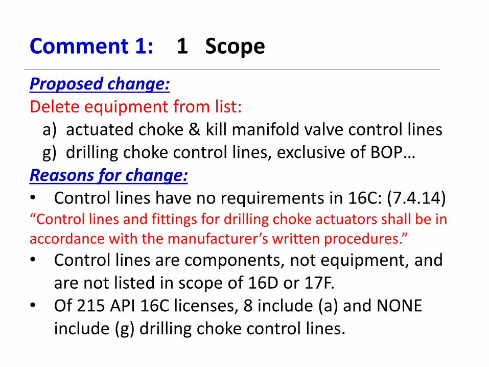
Comment 1: 1 Scope
Proposed change: Delete equipment from list: a) actuated choke & kill manifold valve control lines g) drilling choke control lines, exclusive of BOP… Reasons for change: • Control lines have no requirements in 16C: (7.4.14) “Control lines and fittings for drilling choke actuators shall be in accordance with the manufacturer’s written procedures.”
• Control lines are components, not equipment, and are not listed in scope of 16D or 17F.
• Of 215 API 16C licenses, 8 include (a) and NONE include (g) drilling choke control lines.

Comment 2: 4.1 Service Conditions
Proposed change: Replace: “If severe corrosion, abrasion, temperatures, or high levels of sour gas are expected, the user and manufacturer shall jointly address the requirements and determine the suitable product
for the application.” With: “If severe corrosion, abrasion, temperatures, or high levels of sour gas are expected, it is the responsibility of the user to advise the manufacturer of the requirements and determine the
suitable product for the application.”

Comment 2: 4.1 Service Conditions
Reasons for change: • The manufacturer cannot be required to “jointly
address” requirements with the user, since neither Spec 16C nor the manufacturer can impose requirements on the user.
• “Choosing material class and specific materials for specific conditions is ultimately the responsibility of the purchaser.” (6A clause 4.2.3.2) Manufacturers cannot predict or control operating conditions.
• Well control flow conditions cannot be reasonably or accurately reproduced by the manufacturer for product performance testing.

Comment 3: 4.2 Product Specification
Proposed change: Replace: “The following products have requirements established in API 6A and shall have a minimum of product specification level of PSL 3, Material Class EE or higher…” With: “The following products have requirements established in API 6A and shall have a minimum product specification level of PSL 3, Material Class DD, EE, FF or HH, with an H2S rating of 0.5 psia (3.45 KPa) or higher…”

Comment 3: 4.2 Product Specification
Reasons for change: • The previous draft had changed both PSL & Material
Class: (1.4.2:) “Products listed in 1.2.2 that have requirements established in API 6A shall have a minimum of product specification level PSL 2, Material Class DD or higher…”
• There is no technical advantage to EE over DD. • It is not sufficient or compliant with 6A to specify
M/C DD, EE, FF or HH without the NACE H2S limit. • “Or higher” does not specify what characteristics
are to be higher. 6A material classes are not intended to be ranked alphabetically.

Comment 3: 4.2 Product Specification
Reasons for change, continued: • DD can be more suitable for choke & kill system
applications than EE, depending on the SST used: MATERIAL CLASS
BODY/BONNET MATERIAL
STEM MATERIAL
GATE & SEAT MATERIAL
GATE & SEAT COATING
MAXIMUM H2S RATING
MAXIMUM CO2 RATING
DD-NL* 4130 STEEL 718 CRA 4130 STEEL STELLITE 3 NO LIMIT 30 PSIA
EE-0.5 4130 STEEL 17-4PH SST 410 SST STELLITE 3 0.5 PSIA 30 PSIA
COMPARE NO DIFFERENCE
DD-NL* SUPERIOR
NO BENEFIT TO EE-0.5
NO DIFFERENCE
DD-NL* SUPERIOR
NO DIFFERENCE
• The only difference between DD & EE is the base material requirement for stems, gates, seats, & choke trim, and 12-Cr SST offers no real advantage over low alloy steel with similar coatings/overlays.

Comment 4: Table 1: Equipment Bore Sizes and Rated Working Pressure Proposed change: Add to Table 1:
• 5-1/8 (130) 10,000 (69.0) • 5-1/8 (130) 15,000 (103.5)
Reason for change: • Expected future demand for 5-1/8” choke and kill
manifolds. • All 6A components exist, so there is no reason to
exclude 5-1/8” 10-ksi and 15-ksi manifolds.

Comment 5: Table 4: Temperature Rating for Metallic and Nonmetallic Materials and Flexible Lines Proposed change: Delete from Table 4 and Table 9 (Impact testing):
Rating Y: 0 to 650 °F (–18 to 343 °C)
Reason for change: • Temp Class Y is for steam or geothermal service,
and is well beyond both current HT requirements and capabilities for choke and kill systems.
• Limited data on material properties at 650 °F. • For these reasons, Temp Class Y is not in Spec 6A
requirements, only in an informative annex.

Comment 6: Table 4: Temperature Rating for Metallic and Nonmetallic Materials and Flexible Lines Proposed change: Replace (from bottom of Table 4):
“NOTE The use of multiple ratings is permitted.” With:
“NOTE The use of combined or multiple ratings is permitted.”
Reason for change: • A combined rating provides a wider temperature
rating, e.g., P+U = -20 °F to 250 °F. • A multiple rating provides a choice of ratings, e.g.,
P, X = -20 °F to 180 °F or 0 °F to 250 °F.

Comment 7: Table 25: Hydrostatic Test Pressures
Proposed change: Add “(minimum)” to title of Table 25:
Hydrostatic Test Pressures (minimum)
Reason for change: • Test pressure requires some tolerance. • Same change was made to Spec 6A in 20th edition.

Comment 8: 7.5.12 Assembled Manifold
Proposed change: Replace: “The manifold assembly shall be subjected to a hydrostatic test in accordance with 7.5.4 prior to shipment from the assembler’s
facility. …” With: “The manifold assembly shall be subjected to a hydrostatic test in accordance with 7.5.4, except that for manifolds assembled entirely with equipment that, other than loose connectors, has been previously hydrostatically tested, only testing to rated working pressure is necessary. Testing shall be performed prior to shipment from the assembler’s facility. …”

Comment 8: 7.5.12 Assembled Manifold
Reasons for change: • Consistency with Spec 6A requirement for
Christmas trees: Duplicate of wording in 6A Clause 7.4.9.3.4.
• Safety: An assembled manifold is larger than most high-pressure test chambers or pits. It is difficult to bleed all air from an assembled manifold, which can increase the energy stored and thus the risk.
• The test at 1.5 X RWP is to verify structural integrity of the body components, not end connections.

Comment 9: 10.11.4: Temperature Ratings (Hydraulic Drilling Choke Controls)
Proposed change:
Replace: “Components of the choke control system, including power oil shall be capable of functioning as a system at
temperature of -20F (-29C) to 200 F (93.3 C), …” With: “Components of the choke control system, including power oil shall be capable of functioning as a system at temperature of -20F (-29C) to 150 F (66 C), …” .

Comment 9: 10.11.4: Temperature Ratings (Hydraulic Drilling Choke Controls)
Reasons for change: • The maximum temp rating required by 6A & 16C for
hydraulic valve and choke actuators is 150 °F. • Spec 16D specifies that drilling control systems be rated for
either maximum ambient or the maximum operating condition. A list of ambient temperatures is included, and the highest is 140 °F for “tropical” surface use.
• If the ambient temperature at the control panel or manifold is above 150 °F, it will be impossible for personnel to operate either hydraulic or manual valves and chokes.
• The requirement to use hydraulic oil rated for 200 °F rules out some environmentally friendly water-base control fluids.

API 16C 2nd Edition Comments 8/15/2013
Eric Wehner, NOV

Comment 1: Nominal Choke Size
Proposed change:
Marking
Equipment
Articulated Lines Swivel
Joints Unions Rigid Piping
Buffer Chamber
Flexible Choke and Kill Lines Drilling Choke Drilling Choke
Actuators
Choke and Kill Manifold
Assembly
“Spec API 16C” OD Termination OD Nameplate a Nameplate Nameplate
Assembly serial number N/A Termination OD Body and
nameplate Nameplate Nameplate
… … …
Orifice area size c N/A N/A Body and nameplate N/A N/A
a Nameplate marking requirements are satisfied by body marking. b Safety clamp location notation shall be within 3 ft (1 0.9 m) of the end termination or if applicable of the bend stiffener. c In accordance with 10.7.6.

Comment 1: Nominal Choke Size
Reason for change: Align choke size designation for 16C drilling chokes with API 6A and long-standing industry practice.

Comment 2: Drilling Choke Materials
Proposed change: 10.7.11.1 Materials 10.7.11.2 Metallic Materials Materials for bodies, bonnets, plugs, caps, end connections, and parts shall be in accordance with Section 5. Material selection shall conform to API 6A, Material Class EE, FF or HH, with an H2S rating of 1.5 psia (10.34 KPa) or higher. Reasons for change: Add requirements for what types of material are required for drilling chokes.

Comment 3: 4.2 Product Specification
Proposed change: 4.2 Product Specification The following products shall meet the requirements of API 6A and shall have a minimum product specification level of PSL 3, Material Class DD EE, FF or HH, with an H2S rating of 1.5 psia (10.34 KPa) or higher, and a temperature rating from Table 4 as appropriate for choke and kill system applications: (continued on next slide)

Comment 3: 4.2 Product Specification
a) check valves; b) production chokes; c) crosses and tees; d) flanged, studded end and outlet connections; e) flow-through valves; e) hubbed end and outlet connections; f) production choke actuators; g) ring gaskets; h) studs and nuts; i) threaded end connections; j) valve actuators. Valves shall meet the requirements of API 6A and shall have a minimum product specification level of PSL 3, material Class DD, EE, FF or HH, with an H2S rating of 1.5 psia (10.34 KPa) or higher, and a temperature rating from Table 4 as appropriate for choke and kill system applications.

Comment 3: Product Specification
Reason for change: Allowance for M/C DD only required for valves. For most components (tees, crosses, flanges, spools…) there is no difference between DD and EE. “Production chokes” is not a term used in 6A; could cause confusion.

Report to AWHEM on Activities of API SC18 on Quality By: Raouf Naguib
SC 18 on Quality met in Washington DC in Jun 2013. The SC has the following Task Groups:
TG2 – (Chair: Austin Freeman)
Charge: To revise Q1 independently of TS29001 while meeting or exceeding the requirements of ISO 9001, the intent of Q1, 8th edition, and maintaining close alignment in structure and language with Q2.
The work is done. The document is published with a one year implementation date. Color code the new edition, and submit the results to TG8 on the development of a guidance document for input in the content of the document.
TG3 – (Chair: Ed Durante)
Charge: To review issues and develop recommendations for improvements to the API Monogram program.
Request assistance from the SC17 chair for volunteers to work on TG3.
TG5 – (Chair: Stacey Hagen) `
Charge: Oversee the development of Spec Q2 - Quality Management Systems for Service Supply Organizations for the Petroleum and Natural Gas Industries.
Stacy Hagen Took over the chair position. TG finished several beta-test site assessments for various drilling. TG to start performing beta-test assessments on drilling contractors. After the reviews are completed, mock audits will be performed.
TG is charged with Develop language for potential revisions of Spec Q2.
TG6 – (Chair: Bud Weightman)
Charge: To review all API product specifications to cross-functionally identify requirements for welding; the purpose to identify welding criteria to be recommended for use in all product specifications where welding is required.
No activity to report on this TG.
TG7 – (Chair: Gary Devlin)
Charge: To create a life-cycle management system document that provides the means of identifying the continued compliance of product to its original and/or current manufacturing and design requirements and the ability to demonstrate product compliance to original and/or current product standards and industry/product-specific technical and regulatory requirements throughout the product lifecycle.

modified charge of TG7: To create a life-cycle management system document that provides the means of identifying the continued compliance of product to its original and/or current manufacturing and design requirements and the ability to demonstrate product compliance to original and/or current product standards and industry/product-specific technical and regulatory requirements throughout the product lifecycle.
TG8 – (Chair: Kim Wiita)
Charge: To create a document in order to facilitate the use of the new Spec Q1, 9th Edition and to work with API Staff to determine the need for beta-site assessments and/or mock audits based on the new Spec Q1, 9th Edition.
TG started meeting to decide on which way to go and what kind of document to do.

September 10, 2013
API SC19 Well Completion Equipment
API SC19, Well Completion Equipment met June 23, 2013, in Washington DC under chairman Austin
Freeman.. SC19 organizational chart is enclosed.
Summary of TG reports:
19G – Perforating – Mark Brinson
• Progress made toward rewrite with current target of next year for new edition of spec.
• All active API manufacturers will have section 2 or 4 test facilities by the end of this year.
• Charge testing in stressed rock is now fully accepted.
• SC now looking at normalization of test variances among the testers.
ISO 17824 Sandscreens – George Gillespie
• High pressure leak-off testing completed on 74 screens with new pill. Results: Less variability
and higher burst/collapse values
• TG requested two SR3’s: One for testing different gage screens, and one to test metal mesh
screens. The request was approved.
• Target: complete spec rewrite incorporating the new testing by November 2014.
ISO 14998 Completion Accessories – Jeff Lembcke
• FDIS ballot has passed and sent to ISO editors for eventual publication – API back-adoption
could possibly proceed as early as the next SC19 meeting.
• SC19 - motion was made and carried to monitor ISO actions and decide on API action thereafter.
• Interested members should contact Chris Hall and come to the next SC19 meeting prepared to
discuss.
19V Barrier Valves – David McCalvin
• ISO 28781 has been adopted back by API as 19V with a regional annex to correct a few minor
issues and add needed clarification.
19TT1- Downhole Well Test Tools – David McCalvin
• Specification document reported 80% complete (reported 65% complete in January) – completion
still targeted for the end of 2013
• Informative annexes include applications overview and operational recommendations.
• Normative annexes inclusive of: factory acceptance testing, operating envelopes, packer
validation, electrical/electronic requirements.& service center requirements including rental tools.
14A Subsurface Flow Controls – Darren Bane
• Expected to API ballot – fall 2013.
• 14B, led by R. Smith, is expected approximately the same time.

• 14L, Lock Mandrels and Landing Nipples, was reaffirmed, but the group may wish to revisit this
document upon the completion of 14A/B.
19G…. Gas Lift Activities ---- Wayne Maybry
• 19G1 – Side Pocket Mandrels – WG formed
• 19G2 – Flow Control Side Pocket Mandrels – revisions in progress to match Statoil requirements
• 11V5 - Maintenance, Surveillance, Troubleshooting Installations - 2 year extension needed, WG
formed
• 11V6 – Design Continuous Flow – 60% complete (50% complete in Jan 2013)
• 19G8 – Design & Performance Prediction – 45% complete
• 19G9 – Dual Gas Lift Wells – with API for publication
• 19G10 – Intermittent and Chamber Gas-Lift – 90% complete
• 19G11 – Simulation of Gas-Lift Systems – Ballot failed/ requirements too narrow/ to convert to
Technical Report
• 19G12/13/14 – SR3 being drafted for ongoing refinements
• API Book 6 on Gas Lift being turned into a Technical Report - or “Basics” manual --- 3 SR3’s
sent to CSOEM totaling $375K.
Liner Hangers – George Givens
• 3 meetings held thus far
• Considering both conventional and expandable liner hangers
Packers – Rob Hilts
• HPHT validation testing under consideration
• Non-metals requirements under consideration
• Targeting ballot – late 2013
Additional Items of Interest – Roland Goodman
• AISI has alerted new qualities for Oil/Gas steels may be needed by 2025.
• ASTM considering adding material grades modified for the oil and gas industry.
• OGP moving thru two drafts of materials-related standards
• API/ISO/OGP task force reports “little encouragement” to a near term resolution
• SC17 TR8 - guide to implementation of PER 15K-1 in development with other documents
targeted for individual equipment items planned.
A full report of the June meeting may be found at:
http://mycommittees.api.org/standards/ecs/sc19/Meeting%20Minutes/2013/SC19%20Minutes%20-
%20June%202013.pdf
Respectfully submitted,
B. W. White

Austin Freeman, Chair
Wayne Mabry, Vice-Chair
David McCalvin - Secr.
Wayne Mabry
Mark Brinsden
Gaslift Task Group
Perforating Task Group
Rob
Hilts
George Gillespie
Production Packer
Sand Control Screens
Task Group
Task Group
Chris
Hall
Darren Bane
Accessory Eqpmnt
SSSV & SSFC Task Group
Resource Group
David McCalvin
David McCalvin
Barrier Valve Drill Stem Test Tools
Resource Group
Task Group
George Givens
Liner Hanger
Task Group
Enclosure to SC19 report


SC20 REPORT TO AWHEM Sept 10, 2013
API Subcommittee on Supply Chain Management (SC20)
Eric Wehner (NOV), Chair
Jerry Longmire (GE Oil & Gas), Vice-Chair
Most recent meeting
Meeting was held at the E&P Summer Standardization Conference June 26, 2013.
Status of SC 20 Standards
Specification 20A – Carbon Steel, Alloy Steel, Stainless Steel, and Nickel Base Alloy
Castings for Use in the Petroleum and Natural Gas Industry
Rick Faircloth (Cameron), chair of the 20A Work Group.
Status: The First Edition of Spec. 20A was published March, 2012.
Action since last report: Ballot item was completed to change cleanliness requirement for CSL 3
to report results for information only. One negative vote could not be resolved.
Action pending: Revisions will be balloted for published as Addendum 1; voter will be notified
of appeal methods.
Specification 20B - Open-die-shaped Forgings for Use in the Petroleum and Natural Gas
Industry
Joel Russo (FMC Technologies), chair of the 20B Work Group.
Status: First edition published April, 2013.
Action since last report: Page proofs reviewed and standard published.
Action pending: Develop license information form (license application).
Specification 20C – Closed Die Forgings for use in the Petroleum and Natural Gas Industry
Gary Kingry, Ellwood Texas Forge Co., volunteered to chair.
Status: Published, first edition, October 2009.
Action since last report: N/A.
Action pending: Form TG and hold kick-off meeting. Goal is to align requirements with 20B and
20A.
Standard 20D - Non-Destructive Examination (NDE) Services for Equipment Manufactured
in accordance with API Product Specification used in the Petroleum and Natural Gas
Industry
Jim Harris (GE Oil & Gas), WG chair.
Status: Published September 6, 2013.
Action pending: Develop license information form.

Specification 20E - Alloy and Carbon Steel Bolting for use in the Petroleum and Natural Gas
Industry
Tom Goin (TSP), WG chair.
Status: The First Edition was published October 1, 2012
Action since last report: Color coding and audit questions developed by API were reviewed.
Specification 20F - Stainless Steel and CRA Bolting for use in the Petroleum and Natural
Gas Industry
Tom Goin (TSP), WG chair.
Status: New work item, standard number changed from 20H to 20F.
Action since last report: Two meetings have been held, June 25 and August 20.
Action pending: Continue development.
Standard 20G - Qualification of welding suppliers
Bud Weightman, SC18 TG chair.
Status: New standard. Has been pending conclusion of SC18 TG6 welding study.
Action since last SC meeting: Work of welding TG of SC18 was completed.
Action pending: Form TG and hold kick-off meeting.
Standard 20H - Heat treatment services
Joel Russo (FMC Technologies), WG chair.
Status: New standard in development. Standard number changed from 20F to 20H. Targeted
publication in Q1 2015.
Action since last report: Two TG meetings have been held. Scope has been defined to be heat
treatment for final material properties.
Action pending: Continue to develop working draft.
New Standards
Standard 20J - Material distributors and suppliers
Des Burnley (Baker Oil Tools), volunteered to chair TG.
Status: New standard approved by SC. Proposed scope to be material stockists supplying
standard-form materials, including forged bar, mechanical tubing, and plate.
Action since last SC meeting: N/A.
Action pending: Form TG and hold kick-off meeting.
Publication number TBA - Individual Certification of Site Inspectors
Phil Klefas (Saudi Aramco), TG chair.
Status: New standard approved by SC. Proposed scope is development of an API training
program, training manual, and exam to certify third-party inspection personnel.
Action since last report: API issued call for volunteers.
Action pending: No report.

Future standards - Still under consideration (and issues):
o Elastomers/Non-metallic Seals (Issue: Chair and subject matter experts needed.)
o Super Duplex (Issue: ISO 17881 & 17882 have been published replacing NORSOK
standards M630 & M650.)
o Modified F22 (Issue: Material specification could be a departure from SC20 scope; project
could belong in Materials Resource Group.)
Future standards - Previously under consideration and resolved to delete from list:
o Test Laboratories (Issue: Multiple certification standards exist.)
o Painting and Coating (Issue: Many user company standards exist; consensus could be
difficult.)
o Electronic component suppliers: (Issue: Chair and subject matter experts needed.)
New Business
Will Vangeertruyden (Exxon-Mobil) presented a possible NWI to develop a specification for
critical forgings in subsea applications. Issues discussed included overlap with JIP work,
resource availability, and narrow industry application. Tabled pending clarification.
Next Meeting
The next meeting of SC20 will be at the E&P Winter Conference on Standardization of Oilfield
Equipment and Materials in Addison, TX, January 20-24, 2014.
Report prepared August 29, 2013 by Eric Wehner

ASSOCIATION OF WELL HEAD
EQUIPMENT MANUFACTURERS
PO Box 18265, Howe Moss Avenue, Aberdeen, Scotland, AB21 0UJ
Author: David Thompson. Page 1 of 10 AWHEM NS Mom 15th May 2013 Rev 0 (2).Docx
MINUTES OF MEETING NORTH SEA COMMITTEE
2ND QUARTER
15TH MAY 2013
Tor-Na-Coille
BANCHORY
ABERDEENSHIRE
AWHEM MISSION STATEMENT The mission of the Association of Well Head Equipment Manufacturers is to proactively influence value-added standardization of well head and related equipment in a positive, professional manner and to serve as technical consultants to national and international standards bodies.

ASSOCIATION OF WELL HEAD
EQUIPMENT MANUFACTURERS
PO Box 18265, Howe Moss Avenue, Aberdeen, Scotland, AB21 0UJ
Author: David Thompson. Page 2 of 10 AWHEM NS Mom 15th May 2013 Rev 0 (2).Docx
Agenda 1 HSE Brief and Orientation 09:10
2 Welcome and Apologies 09:15
3 Round the Table introductions 09:15
4 Review Minutes of the Previous Meeting Approval of previous Minutes Review outstanding actions from Previous Minutes University of Aberdeen AWHEM Prize
09:20
5 Treasurer’s report 10:10
6 Chairman’s Correspondence Mail received New Members
10:15
7 Review AWHEM US minutes from Last meeting 10:20
Break for Tea and Coffee 10:20 - 10:45
8 Presentations by James Savage & Dr Simon Leefe - Wilde Analysis
Computational Fluid Dynamics and its uses for Valve Design and Reliability.
10:45
Lunch 12:45 - 13:30
9 Future meetings (Venue & Topics) Wed 21st August - Whitfords, Runcorn.
Manufacturers of Xylan Coatings Wed 20th November – Tor Na Coille, Banchory Wed 19th February - Gateshead Hilton Wed 21st May – Tor Na Coille, Banchory
13:30
10 A.O.B. Xodus Presentation:- Assessing Pipework integrity using CFD
CFD erosion analysis examples – chokes, Xmas trees, flow lines, water & cuttings reinjection
Vibration analysis for subsea Xmas trees, jumpers and manifolds – CFD & FEA

ASSOCIATION OF WELL HEAD
EQUIPMENT MANUFACTURERS
PO Box 18265, Howe Moss Avenue, Aberdeen, Scotland, AB21 0UJ
Author: David Thompson. Page 3 of 10 AWHEM NS Mom 15th May 2013 Rev 0 (2).Docx
Thermal analysis – Gas injection annulus case, insulation and trapped water/doghouse assessment
Joule Thompson example Cavitation erosion in water injection chokes
Close of Meeting

ASSOCIATION OF WELL HEAD
EQUIPMENT MANUFACTURERS
PO Box 18265, Howe Moss Avenue, Aberdeen, Scotland, AB21 0UJ
Author: David Thompson. Page 4 of 10 AWHEM NS Mom 15th May 2013 Rev 0 (2).Docx
See Attachment 1 for list of Attendees & Apologies.

ASSOCIATION OF WELL HEAD
EQUIPMENT MANUFACTURERS
PO Box 18265, Howe Moss Avenue, Aberdeen, Scotland, AB21 0UJ
Author: David Thompson. Page 5 of 10 AWHEM NS Mom 15th May 2013 Rev 0 (2).Docx
Minutes of May 2013 Quarterly Meeting 1 Opening, HSE Brief and Orientation.
Paul Shillito opened the meeting and gave the meeting the HSE briefing for the day, noting the appropriate emergency escape routes and assembly points and advised that there were no expected fire drills that day.
09:10
2 Welcome Paul then welcomed all AWHEM Members to the meeting, before asking if all had signed the attendance sheet and added any further apologies. See Attachment 1 for list of Attendees & Apologies.
09:15
3 Round the Table introductions Each attendee gave a brief introduction for the benefit of the other attendees.
09:15
4 Review of the Previous Meeting Before reviewing the minutes of the previous meeting, Paul Shillito commended Marie Mitchell in her absence for her service and organisation as Association Chair in the previous year and her assistance in planning this year's activities.
a) Review & Approval of previous Minutes Item 4:- APOS Standards. At the previous meeting Ian Hamilton advised some success through Aker channels and Statoil had been asked to issue some formal guidance, but no information has been forthcoming. As Ian had now moved on, there was no update from Aker on any response. John Cullion advised that new Technical Requirements (in TR2XXXX series) documents were being added to Statoil enquiries as mandatory compliance requirements. Archie Fleming also advised that these were also being imposed on bolting. This is a matter of concern, as it appears that Statoil are introducing preferential standards by a back-door method, introducing materials and design requirements through standards presented as limited to work methodology only and contravening the intent of the Norsok & other standards. API. It was agreed that the US committee would be requested to
09:20

ASSOCIATION OF WELL HEAD
EQUIPMENT MANUFACTURERS
PO Box 18265, Howe Moss Avenue, Aberdeen, Scotland, AB21 0UJ
Author: David Thompson. Page 6 of 10 AWHEM NS Mom 15th May 2013 Rev 0 (2).Docx
Minutes of May 2013 Quarterly Meeting provide early notification of documents for ballot and for copies of any relevant committee minutes or other correspondence to be forwarded to the North Sea Committee via the Secretary. Golf. Several members noted that they had not received the e-mails regarding the golf outing arrangements. All members were again requested to check that their details were up to date on the membership listing. AWHEM Prize. Following review of the initial draft of the agreement, it was agreed that the revised aim met the aims of the Association and that it should now commence in 2014, subject to agreement with the college of some outstanding clarifications Item 6 - Chairman's Correspondence. No comments Item 7 - AWHEM (US) Minutes. No new minutes had been received. Item 9 - AOB:- The Statoil J.I.P. on long term seal performance has currently pulled one tree for inspection of the seals & a follow-up meeting is scheduled for March. Additional trees and other long term subsea equipment from other end-users [BP, Conoco-Phillips] are also being pulled and Alan Bickley is expecting to receive the results of the meeting & inspections and will report back at the next quarterly meeting. Action Alan Bickley. The previous minutes were then proposed as a true & correct record of the meeting by Trevor Smith & seconded by Archie Fleming
b) Review outstanding actions from Previous Minutes See Separate Actions List for Updates. BP Risk Management / Post Macondo presentation. This date of this presentation remains uncertain due to personnel changes in BP.

ASSOCIATION OF WELL HEAD
EQUIPMENT MANUFACTURERS
PO Box 18265, Howe Moss Avenue, Aberdeen, Scotland, AB21 0UJ
Author: David Thompson. Page 7 of 10 AWHEM NS Mom 15th May 2013 Rev 0 (2).Docx
Minutes of May 2013 Quarterly Meeting See Action List for details.
5 Treasurer’s report. Outstanding Fees Due & Non-Payments for 2011. Due to changes in the office bearers of the association, it would be necessary to change the signatories for the Association's cheques. It was agreed that the new signatory would be David Thompson. As Martin was unable to attend the Action on him to arrange the necessary paperwork remains outstanding. Invoices have been prepared & sent for the members for 2013. Prompt payment was requested from the members & most had now paid. It was noted that the current balance of funds was some £20,140 and whilst this is not a large amount, it remains healthy.
10:10
6 Chairman’s Correspondence Mail received
- No mail had been received and the mailbox service is being allowed to lapse
Membership changes Claxton had made an approach with a view to joining AWHEM, but after an initial exchange of information regarding membership requirements, nothing further has happened. It is thought that they are not suitably qualified for membership as they appeared to have limited design capabilities.
10:15
7 Review minutes from last AWHEM US meeting (if available). No minutes were available at this time.
Break 10:20 - 10:45
10:20
8 Presentation by James Savage & Dr Simon Leech - Wilde Analysis:- Computational Fluid Dynamics and its uses for Valve Design and Reliability. [Attachment 2]
10:45

ASSOCIATION OF WELL HEAD
EQUIPMENT MANUFACTURERS
PO Box 18265, Howe Moss Avenue, Aberdeen, Scotland, AB21 0UJ
Author: David Thompson. Page 8 of 10 AWHEM NS Mom 15th May 2013 Rev 0 (2).Docx
Minutes of May 2013 Quarterly Meeting The uses and appropriate application of Computational Fluid Dynamics (CFD) & Finite Element Analysis (FEA).
Dr. Leefe opened his presentation by stating that CFD and FEA analysis techniques are not a panacea for all problems and cautioned against an absolute belief in the results from any computer analysis, advising that knowledge gained through practical experience was key to identifying incorrect predictions from analyses. He stressed that it was important to remember that these techniques were simulations only, and their predictions were limited by key factors such as:
o The accuracy of the mathematical description of the system being analysed.
o The accuracy of the initial state information o Assumptions made in defining the system boundaries o Unknowns
Dr Leefe added that it was important that anyone assessing or working from information derived through CFD or FEA clearly understood these limitations and applied appropriate safeguards to mitigate for these. Prime among the mitigation strategies is to use selective testing at or around key boundary conditions to verify the predictions of the analyses. Dr. Leefe advised that due to the above, caution be exercised when selecting appropriate tasks for CFD and FEA analyses. CFD he advised was particularly limited in the case of multiphase flow regimes due to the difficulties in modelling the unsteady flow conditions, droplet size, gas solubility & mass transfer rates between phases and as a result, the optimal "safe" use for CFD in this situation is as a "snapshot" only. Similarly, the use of both techniques is very limited in thermal analysis. Finally before proceeding with the slide presentation, Dr. Leefe emphasised the careful selection of situations and systems by experienced personnel, based on previous experience and understanding of the fundamentals of the system being analysed, giving examples of critical considerations [See Attachment 3]

ASSOCIATION OF WELL HEAD
EQUIPMENT MANUFACTURERS
PO Box 18265, Howe Moss Avenue, Aberdeen, Scotland, AB21 0UJ
Author: David Thompson. Page 9 of 10 AWHEM NS Mom 15th May 2013 Rev 0 (2).Docx
Minutes of May 2013 Quarterly Meeting James Savage then gave a brief presentation on Reliability & Risk, again cautioning on the correct use of data and need for applying intelligence to the results obtained from any analysis. Following a question and answer session, Paul Shillito thanked both speakers for their clear and instructive presentation.
Lunch 12:45 - 13:30
9 Future Meetings:
August Meeting:- It was confirmed that the meeting venue will be Whitfords, manufacturers of Xylan coatings for studs & nuts, based in Runcorn, Cheshire. An invitation with relevant details for attendees will be circulated in the usual manner later in the year. November Meeting:- David Thompson confirmed that Richie Barker had agreed to attend the November meeting to give a presentation on the implementation and adoption of Computed Radiography. Future Meetings: - It now appeared that the next available date for NAMTEC to attend and present on subsea materials & selection would be some time in 2014. However, it was hoped that this might be pulled forward, if suitable people were available to attend the August or November meetings. Paul Shillito to confirm.
13:30
10 Any other business: Presentations:- Considering the topic of today's presentation, it was agreed to accept the offer of a presentation on a similar theme by XODUS, but as a a future presentation for 2014. DNV JIP on Forgings:- John Cullion advised that there was a JIP being proposed by DNV on large forgings for use in producing subsea materials and components. This JIP was to establish & promote best practices and
13:45

ASSOCIATION OF WELL HEAD
EQUIPMENT MANUFACTURERS
PO Box 18265, Howe Moss Avenue, Aberdeen, Scotland, AB21 0UJ
Author: David Thompson. Page 10 of 10 AWHEM NS Mom 15th May 2013 Rev 0 (2).Docx
Minutes of May 2013 Quarterly Meeting would involve companies based in the US, UK & Norway. John Cullion agreed to represent AWHEM's interests in this JIP. It was anticipated that this would kick off around the 25th of May 2013. Golf Outing:- It was noted that perhaps due to the communications issue mentioned above, only 12 members & guests had attended the golf outing, but the clubs are requiring groups of at least 15 players before offering any discount, and members were urged to attend next year's outing. This year's outing had been won (again) by Ronnie Whyte.
13:50 Close of Meeting
List of Attachments Ref Description 1 Attendees & Apologies 2 Computational Fluid Dynamics and its uses for Valve Design and Reliability 3 Key Considerations for Accuracy in CFD / Reliability & Risk 4 Reliability & Risk Presentation


www.wildeanalysis.co.uk 0161 474 7479 Simulation in the Design of Reliable Equipment
Simulation in the Design of Reliable Equipment
AWHEM Meeting, Aberdeen, May 15th 2013
Dr. Simon Leefe Technical Director, CFD
Simulation in the Design of Reliable Equipment
optimising design by analysis
James Savage Business Development Manager

www.wildeanalysis.co.uk 0161 474 7479 Simulation in the Design of Reliable Equipment
Who am I?
James Savage BEng (Hons), MBA, CEng, MIMechE
• Reliability Lead • Wilde Analysis Ltd
• Address: Brindley Lodge, Adcroft Street, Stockport, Cheshire, SK1 3HS • Telephone: 0161 474 7470 • Email: [email protected]
• 10+ years in Consulting Engineering, including FEA, Reliability and Manufacturing
• UK Reliability Technical Support and Training
James Savage

www.wildeanalysis.co.uk 0161 474 7479 Simulation in the Design of Reliable Equipment
Who am I?
Simon Leefe BA (Oxon), PhD, CEng, FIMechE, AMChemE
• Technical Director, CFD • Wilde Analysis Ltd
• Address: Brindley Lodge, Adcroft Street, Stockport, Cheshire, SK1 3HS • Telephone: 0161 474 7470 • Email: [email protected]
• 30+ years in fluid and solid mechanics, including 15+ years in world-leading fluid sealing R&D group
• 20+ years in consulting, especially computational fluid dynamics • Fluid Dynamics and Multiphysics modelling, simulation and design
guidance
Simon Leefe

www.wildeanalysis.co.uk 0161 474 7479 Simulation in the Design of Reliable Equipment
Solutions About Wilde Analysis

www.wildeanalysis.co.uk 0161 474 7479 Simulation in the Design of Reliable Equipment
• Formed in 1980 as Finite Elements Ltd • 1200+ clients, including:
• Member of Wilde Group of 70+ employees • 28 employees directly involved in analysis sales, services & admin (25
are engineers) • ISO 9001:2008 approved QMS • On UK Steering Committee for NAFEMS • Involved with many industry associations
Analysis About Wilde Analysis

www.wildeanalysis.co.uk 0161 474 7479 Simulation in the Design of Reliable Equipment
Mission
To optimise the design of our clients’
products & processes by providing ‘best
of class’ analysis solutions
Wilde Analysis Mission Statement

www.wildeanalysis.co.uk 0161 474 7479 Simulation in the Design of Reliable Equipment
• About you • About Wilde Analysis • Simulation: why, when and what?
– Main focus on fluid-handling applications
• Typical relevant application areas • Brief technical explanation • Illustrative examples • Getting the most out of simulation • Discussion
Analysis Agenda

www.wildeanalysis.co.uk 0161 474 7479 Simulation in the Design of Reliable Equipment
• What does ‘analysis’ and ‘simulation’ mean to you? • Anybody used CFD or FEA? • How successfully? • How do you see the connection between safety, reliability, design and
analysis? Does this extend beyond control systems? • What role do you see for analysis and simulation?
Analysis About you

www.wildeanalysis.co.uk 0161 474 7479 Simulation in the Design of Reliable Equipment
Optimise product & process design more efficiently and effectively
Add value • Evaluate options early in design process to save on more expensive design
changes later • Provide insights otherwise unobtainable at reasonable cost, hence steer
design thinking • Replace or reduce physical testing where not possible or cost-effective • Characterise equipment
o understand / improve / optimise performance o use in model of system behaviour
• Inform lifetime estimation
Simulation toolkit • CFD (computational fluid dynamics) • FEA (finite element analysis) • Reliability: various statistical techniques Clearly focussed on design process
Simulation: Why, When and What?
Focus of presentation

www.wildeanalysis.co.uk 0161 474 7479 Simulation in the Design of Reliable Equipment
Simulation in Process Engineering
Conceptual
Basic eng’g
Detailed eng’g
Commission
Workover and Intervention
Decommission
+ Safety case
Evaluate specific alternatives
Optimise
Troubleshooting Diagnostics
Evaluation: - Downhole tools
- Changed op conds
Compliance
Hazard evaluation
Development studies: - Complex interactions - Understand behaviour
Simulation in the lifecycle
Life extension
Equipment evaluation

www.wildeanalysis.co.uk 0161 474 7479 Simulation in the Design of Reliable Equipment
Cv values • Minimise losses, maximise flow
System pressure and flow balancing • Design for intended flow split in a network • Bypass flows
Hydrodynamic forces on sub-assemblies • Valve fully-open flow rate threshold for spring-loaded valves • Actuator loads
Dynamics of opening / closing • Actuation time for safety-critical valves
Lifetime Estimation • Sand erosion • Elastomer seal ageing • Wear in metal seal
Temperature distribution • Seal integrity and operational limits • Insulation U-values
Typical Relevant Application Areas

www.wildeanalysis.co.uk 0161 474 7479 Simulation in the Design of Reliable Equipment
CFD: What and why
• Coupled thermal, hydrodynamic, chemical and physical phenomena
INSIGHT SMART DECISIONS
• Computational Fluid Dynamics – simulates fluid flow
– Traditionally:
• stand-alone models of principal phenomena • simplified geometry
– CFD: • framework for integration • interactions observed • realistic geometry • couple with solid simulations / CAD
CFD: What is it?

www.wildeanalysis.co.uk 0161 474 7479 Simulation in the Design of Reliable Equipment
How Does It Work?
– Transport equation
• conservation statement for quantities transported by the flow – Control volume
• region of space to which conservation statements for mass, enthalpy, etc. are applied
Net inflow by convection
Net inflow by diffusion + Sources +
Rate of appearance
Sinks -
Rate of disappearance
• CFD applies transport equation to connected control volumes:
Rate of increase =
Zero for steady- state problems
• Key ideas
CFD: Brief Technical Explanation

www.wildeanalysis.co.uk 0161 474 7479 Simulation in the Design of Reliable Equipment
The Grid
Divide region of interest
• Flow across face of one control volume = flow into neighbouring
control volume • This linkage gives large set of simultaneous equations
CFD: Brief Technical Explanation
into set of small connected control volumes (“the grid”)

www.wildeanalysis.co.uk 0161 474 7479 Simulation in the Design of Reliable Equipment
Results
• Solve equations by iterative matrix methods
– Numerically • Flow rates, reaction forces, erosion rate, peak Mach number , exit temperature,
etc.
CFD: Brief Technical Explanation
• Interpret results – With graphical tools

www.wildeanalysis.co.uk 0161 474 7479 Simulation in the Design of Reliable Equipment
• Replace physical test to obtain Cv value from pressure drop vs flow rate • Pinpoint origins of losses and steer design improvements (increase Cv)
Cv Values
Example: stab connector
Streamlines coloured by velocity

www.wildeanalysis.co.uk 0161 474 7479 Simulation in the Design of Reliable Equipment
• Obtain Cv or loss coefficient vs % open
Cv Values
Contours of total pressure
Example: non-return valve

www.wildeanalysis.co.uk 0161 474 7479 Simulation in the Design of Reliable Equipment
• Characterise valves by loss coefficients derived from CFD (see previous slide)
• Use in flow network analysis • Include hypothetical restriction as variable loss coefficient • Determine value(s) to give desired flow split • Size corresponding orifice / restriction
System pressure and flow balancing
ZONE 1 ZONE 2
Depth xxx ft Depth xxx ft
Pressure xxx psi Pressure xxx psi
Required flow xxx bbl/day Required flow xxx bbl/day
ZONE 3
Depth xxx ft
Pressure xxx psi
Required flow xxx bbl/day
1
2
3 4
5
6 7
orifice2 orifice5
orifice8
Ko2 Ko5
K13 K46
9K34 Ko8 K89
pipe
K45'
K78
K12'
8
4
5
6A5B5
6

www.wildeanalysis.co.uk 0161 474 7479 Simulation in the Design of Reliable Equipment
Use force coefficients • Characteristic of geometry • Derive from CFD at one flow condition • Use to calculate force at arbitrary flow rate with fluid of different density • Example: lift coefficient characterises aircraft wing at any speed or altitude • Restrictions: turbulent incompressible flow (OK for weakly compressible)
Hydrodynamic forces
ρ, u
CFD → actuation torque @ few angles, θ → CT(θ) (curve fit)
θ
Actuation torque at any angle, θ for fluid of any density, ρ at
any mean velocity, u:
𝑻 = 𝑪𝑻 𝜽 .𝝅𝑫𝟐
𝟒. 𝑫. 𝟏
𝟐𝝆𝒖𝟐
D

www.wildeanalysis.co.uk 0161 474 7479 Simulation in the Design of Reliable Equipment
• Example: subsea safety valve (HIPPS) • Slab gate valve held open against spring force by hydraulic actuator
pressure • CFD → actuation force as f(% closed)
• see previous slide for conceptual approach • CFD → Cv values for hydraulic pressure dump valve and fittings in
pressure dump line • see earlier slides on determining Cv
• Equation of motion for actuator + gate moving assembly • Input / results via Excel spreadsheet with embedded routine to solve
equation of motion • Use Excel to plot graphs of forces, pressures, displacements etc vs time • Gate displacement vs time → valve closure time
• Explore system behaviour and identify/evaluate risk for control system design options
• Examine effect of hydraulic system (e.g. line bore) on closure time • Identify if friction prevents closure • etc
Valve closure dynamics (1)

www.wildeanalysis.co.uk 0161 474 7479 Simulation in the Design of Reliable Equipment
Valve closure dynamics (2)
Gate friction from gate lateral
force arising from pressure difference
across gate
Weight
Seawater plus hydraulic pressure
Seawater pressure
Seawater pressure
Fluid pressure (non-uniform)
Net vertical fluid force (“stem ejection force”) ►
Seal friction
Spring force
Forces on gate ass’y in dir’n of motion High-integrity pipeline protection system
(HIPPS) valve in closed position
Flowline
CFD characterisation
Hydraulic dump line (connected to control system)
= dump line back-pressure
CFD characterisation
1.E-02
1.E+00
1.E+02
1.E+04
1.E+06
1.E+08
1.E+10
0 0.2 0.4
K_
v
Gate travel (m)
K_v from CFD
curve fit
extrapolation
Obtained from CFD-derived loss coefficient

www.wildeanalysis.co.uk 0161 474 7479 Simulation in the Design of Reliable Equipment
Valve closure dynamics (3) Tr
avel
(mm
)

www.wildeanalysis.co.uk 0161 474 7479 Simulation in the Design of Reliable Equipment
• Sand erosion model available • Implemented with particle tracking • Uses empirical relationship for erosion rate, E, in terms of particle
mass flow rate, mp, impact velocity Up, and angle, α, for given material combination
𝑬 = 𝒎𝒑𝑲 𝑼𝒑𝒏
𝒇 𝜶 • CFD tracks suitable number of particles, collates statistics of particle-
wall collisions and scales results for nominal flow rate of solids
Erosion
Erosion rate on pipe bend [kg.s-1.m-2]
0
0.2
0.4
0.6
0.8
1
1.2
0 10 20 30 40 50 60 70 80 90f(a
)
a (deg)

www.wildeanalysis.co.uk 0161 474 7479 Simulation in the Design of Reliable Equipment
Elastomer seal life prediction
Initial contact stress → sealing
Diffusion
C ( x, y, z, t ) Behaves like thermal conduction
ageing (chemical reaction)
permanent set changed properties
reduced contact stress over time
Concentration change
Possible loss of seal
Simulate in ANSYS
Workbench
Elastomer seal ageing

www.wildeanalysis.co.uk 0161 474 7479 Simulation in the Design of Reliable Equipment
Critical metal seal (details confidential) • Subject to transient thermal loading (flow / no-flow cycles in hot well) • Gives rise to differential thermal expansion • Different radial expansions increase clearance, hence reduces sealing stress • Axial distortions cause sliding, hence wear • Contact pressure less on subsequent cycles due to plastic deformation in 1st cycle
Metal seal wear
Tube hanger seal pocket temperatures
0
20
40
60
80
100
120
140
160
180
200
1.0E+01 1.0E+02 1.0E+03 1.0E+04 1.0E+05 1.0E+06
time (sec)
tem
p (d
egC
)
seal pocket ID tempseal pocket OD tempDifference peak temperature
diff: 94 degCxxx
Tube hanger seal pocket radial displacements
-1.5E-04
-1.0E-04
-5.0E-05
0.0E+00
5.0E-05
1.0E-04
1.5E-04
2.0E-04
2.5E-04
3.0E-04
1.0E+01 1.0E+02 1.0E+03 1.0E+04 1.0E+05 1.0E+06
time (sec)ra
dial
dis
pl (m
)
ID radial displOD radial displDiff (-ve is compressive)
max red'n in seal pocket w idth = 0.129mm (c/f clearance of 0.14 mm above seal pocket)
xxxxxxxx xxxxx

www.wildeanalysis.co.uk 0161 474 7479 Simulation in the Design of Reliable Equipment
Transient thermal analysis
• Site pup weld simulation (simplified) • Valve pre-assembled and welded on site • Can leave static seals (e.g. PTFE)
vulnerable to overheating
Typical valve geometry
Model geometry (simple representation for illustrative example)
Heat source run around this outer surface
Seat ring
Part of body
Temperature monitor points

www.wildeanalysis.co.uk 0161 474 7479 Simulation in the Design of Reliable Equipment
Transient thermal analysis
100
120
140
160
180
200
220
240
260
0 2 4 6 8 10
Tem
per
atu
re (
de
g C
)
Time (min)
P1
P2
P3
P4
P5
P6
Pre-heat temp
Peak temp at seal pocket: 242 degC
• Note: in this example, potential problem for PTFE-based seat seal
Click to animate

www.wildeanalysis.co.uk 0161 474 7479 Simulation in the Design of Reliable Equipment
Getting the most out of simulation
• Resources - Software: ANSYS CFD in Workbench - Hardware: typically multi-core desktop PC (8-16 processors advisable), but
can run in serial on laptop - People: for best results need someone who understands fluid mechanics
and the models and assumptions that are involved in simulation • Identification of problem essentials: abstraction • Getting maximum information for minimum simulation • Choice of models, methods, boundary conditions, etc. • Getting a solution
- Numerics - Convergence not the same as accuracy
• Results interpretation • Validation

www.wildeanalysis.co.uk 0161 474 7479 Simulation in the Design of Reliable Equipment
Validation
Validated modelling approach
Established test cases or relevant data
Flow problem formulation
Process models (e.g. reaction
kinetics)
CFD solver
Simulation results
• CFD relies on models and assumptions: validation of simulation approach important for new class of problem
• In most instances, sufficient experience exists
Validation
Comparison

www.wildeanalysis.co.uk 0161 474 7479 Simulation in the Design of Reliable Equipment
Validated CFD modelling approach
Design optimised or problem solved
Design development / evaluation
Trial configuration Results
Goals and constraints
Data from related trials
Evaluation
Design with validated method
Recent advances in automated
optimisation

www.wildeanalysis.co.uk 0161 474 7479 Simulation in the Design of Reliable Equipment
Discussion
• Questions • Comments

ASSOCIATION OF WELL HEAD
EQUIPMENT MANUFACTURERS
PO Box 18265, Howe Moss Avenue, Aberdeen, Scotland, AB21 0UJ
Author: David Thompson File:Minutes Attachment 3 2013_May.Docx Revised by: David Thompson Date created: 28th June 2013
Page 1 of 2 Date of Revision :11/7/12
AWHEM North Sea Committee Meeting 2nd Quarter 2013
Tor-Na-Coille Hotel, Banchory
Attachment 3 to Minutes Key Considerations for Accuracy in CFD
1 CFD (&/or FEA) is most effective when used as early as possible in the design phase and can be particularly effective as an early phase design discriminator to assess design options.
2 Boundary Conditions must be:- Appropriate to the system being analysed Accurate
3 Caution must be observed to (very) accurately describe: Boundary Layer Flow Conditions Unsteady Conditions Flow through small / narrow gaps with larger parallel flow paths
4 It is better to avoid situations of: Large thermal gradients in the flow, where these change the
assumed fluid properties Significant temporal variation in flow boundaries Analysis based on extrapolation outside of the range of test data
5 All data must be:- Realistic Achievable (i.e. within the limits of the system) Properly Delimited (e.g. where condensation of gas limits rising
pressure or dropping temperature causes might result in hydrate, waxing or other solid formation)
6 All simulations are susceptible to Garbage in Garbage Out, hence the results must be taken in context and be proven reflective of true system behaviour before being accepted.
7 Any tools, analogies or boundary conditions must be appropriate to the system being analysed.

ASSOCIATION OF WELL HEAD
EQUIPMENT MANUFACTURERS
PO Box 18265, Howe Moss Avenue, Aberdeen, Scotland, AB21 0UJ
Author: David Thompson File:Minutes Attachment 3 2013_May.Docx Revised by: David Thompson Date created: 28th June 2013
Page 2 of 2 Date of Revision :11/7/12
Key Considerations for Accuracy in CFD 8 Analysis and interpretation of results benefits greatly from the use of
highly skilled and practiced personnel. The occasional user will be very likely make errors in the basic analysis definition and will be unlikely to be able to detect these errors in the analysis output.
9 Analysis should be verified by testing at appropriate points.
Key Considerations for analysis of Reliability & Risk 1 Input Data must be obtained Reliably 2 Input Data must be realistic, i.e. reflect the expected service conditions 3 Input Data must not be used indiscriminately, i.e. not all data is good data 4 Feedback on actual performance is key to obtaining good input data and
good results 5 New Designs must include reliability feedback or there is no point in
producing new designs 6 Again, reliability analysis is most effective when undertaken as early as
possible in the design process, but can bring benefits at any stage.

www.WildeFEA.co.uk© Wilde FEA Ltd. 2009
improving design by simulation
Introduction to Reliability EngineeringIntroduction to Reliability Engineering29th July 2009
Mike McCarthyReliability Specialist
Wilde FEA Ltd
Wilde Webinar Series

www.WildeFEA.co.uk© Wilde FEA Ltd. 2009
“But the design looked good on paper”

www.WildeFEA.co.uk© Wilde FEA Ltd. 2009
What is Reliability & Reliability Engineering?

www.WildeFEA.co.uk© Wilde FEA Ltd. 2009
Definitions and terminology
Definition of Reliability:• The ability of an item to perform a required function under
stated conditions for a stated period of time Source: BS 4778 or MOD Defence Standard 00-40
or• It is the probability R(t) that an item can perform a required
function without failure under given conditions for a given timeinterval.
Reliability…• Deals with orders of magnitudes not decimal places• Strong on comparison and trends but weak on absolutes

www.WildeFEA.co.uk© Wilde FEA Ltd. 2009
What is Reliability Engineering?
A multidiscipline process that attempts to…• ensure product or process capability• predict product/process failures • understand why the failures occurred • improve the product/process in an objective way• give insight into spare parts stocking, contractual
compliance, maintenance planning, warranty budgeting…
• provide evidence for dependability claims• etc…
Basically it is good ‘engineering’ practice throughout the product/process lifecycle

www.WildeFEA.co.uk© Wilde FEA Ltd. 2009
Quality vs. Reliability
Quality is…• The extent to which internal processes, procedures &
documentation are free from defects.• The level to which a product conforms to requirements at the
start of use.• Concerned with performance at ONE point in time – usually at
point of manufacture.• Performance = ‘compliance to specification’
Reliability is…• The extent to which a product CONTINUES to conform to
requirements• Concerned with performance of a product or process over its
operational lifetime.• A function of time, cycles, miles, operations…
Reliability = “Quality over time under stated conditions”

www.WildeFEA.co.uk© Wilde FEA Ltd. 2009
6σ vs. Reliability
6σ is usually regarded as a process quality goal (3.4 defects per million opportunities)Methodology is: Define, Measure, Analyse, Improve, Control • Change management driven by statistics
Designing for reliability has wider scope• Quality & variability of components and manufacturing process• Accuracy of operating environment to design specification
6σ requires Statistical Process Control…Reliability tools are used within 6σ (FMEA, FRACAS, HALT, FTA, Root Cause Analysis…)
6s is a framework to apply reliability tools

www.WildeFEA.co.uk© Wilde FEA Ltd. 2009
Reliability, Dependability and Liability
End user
Supply chain
Manufacturer
Your seal leaks!
LiabilityControl?
This is all about risk
management

www.WildeFEA.co.uk© Wilde FEA Ltd. 2009
Likelihood-Consequence Curve
Likelihood (frequency)Impossible Certain
to occur
Consequence
Catastrophic
Negligible
‘Acceptable’
Prohibited
ALARP

www.WildeFEA.co.uk© Wilde FEA Ltd. 2009
Why is Reliability Important?
Liability/SafetyProduct performanceCost• Warranty costs• Product recalls/campaigns• Cost of ownership for the customer • ‘Hidden factory’ costs
– Overtime, rework, downtime, audits and inspection…
Competitive marketplaceCustomer satisfaction

www.WildeFEA.co.uk© Wilde FEA Ltd. 2009
Product / Process Life Cycle
Funds Committe
d
Funds
Spent
Life Cycle Cost
TimeStart of life
End of life
LCC cost reduction opportunity
Increasing difficulty/cost to fix problems
Pre-Production
Design
Volume ProductionIn-Field
Concept Simulation & Prediction
‘Decommissioning phase for some
products’

www.WildeFEA.co.uk© Wilde FEA Ltd. 2009
Why do things fail?
Consider three categories:
• Intrinsically reliable components– Electronics (properly operated), mechanical non-moving
parts, correct software– ie. stuff that does not ‘wear-out’
• Intrinsically Unreliable components– Light bulbs, bearings, drive belts…– ie. stuff that we know will need replacements - they ‘wear-
out’
• Systems– Many components & interfaces – many ways to fail– eg cars, dishwashers, laptops (!!)…

www.WildeFEA.co.uk© Wilde FEA Ltd. 2009
Why do things fail?
The design is inherently incapable• eg. too weak, exhibits a resonance…The product is overstressed• eg. tyre is over inflated, voltage too high…The population exhibits strength variation• some items are weaker than others in the same environment…Failures occur from wear-out• Degradation over time from fatigue, corrosion, evaporation…Failures arise from errors• eg. errors in specification, software coding, poor assembly,
incorrect maintenance, incorrect use, incorrect operating instructions…
Any others?…When do they occur?

www.WildeFEA.co.uk© Wilde FEA Ltd. 2009
Why do things fail?
0
Probability
ValueS
Can the product in this application fail?Yes – when L exceeds S
L S
In reality Operating Loads (L) and Component Strength (S) are distributions:
L
Proportion of the population
failing

www.WildeFEA.co.uk© Wilde FEA Ltd. 2009
Failure Rate
TimeT2T1
‘Wear-in’ ‘Wear-out’
‘Random’
0
The bath-tub curve
Applicable in many areas of engineering
Applies to humans as well!
Weak design Assembly errors
Damaged components Poor joints/connections
Dirt & contamination
Operating Stresses Poor maintenance
Operator abuse Accidents
Weak design Wear
Insulation breakdown Fatigue
Corrosion
Where are typical failures found?

www.WildeFEA.co.uk© Wilde FEA Ltd. 2009
Human bath-tub curve
Life table for the total population: USA 1997National Vital Statistics Report Vol 47, No.28 Dec.13,1999
00.0020.0040.0060.0080.01
0.0120.0140.0160.0180.02
0.0220.0240.026
0-1
3-4
6-7
9-10
12-1
3
15-1
6
18-1
9
21-2
2
24-2
5
27-2
8
30-3
1
33-3
4
36-3
7
39-4
0
42-4
3
45-4
6
48-4
9
51-5
2
54-5
5
57-5
8
60-6
1
63-6
4
66-6
7
69-7
0
Age
Proportion dying during age interval
Wear-OutApprox > 40yrs
Infant Mortality (Wear-in)Approx < 2yrs
‘Operating Life’(Darwinian!)

www.WildeFEA.co.uk© Wilde FEA Ltd. 2009
What is Reliability?
RCM
CMMS
RGA
ALARP
RCA
MTBF
FRACAS
FME(C)A
B10
KPIs
RBDs
MTTR
FTA

www.WildeFEA.co.uk© Wilde FEA Ltd. 2009
Reliability Plan
FTA
FME(C)ARBDs
Tools/Techniques
Weibull
KPIs
Measures
MTTR
B10 Availability
MTBF
RCA ALARP
FRACASRCM RGA
CMMSSystems/Methodologies

www.WildeFEA.co.uk© Wilde FEA Ltd. 2009
Typical ‘Reliability’ data
“Any port in a storm!”
MeanTimeBetweenFailure

www.WildeFEA.co.uk© Wilde FEA Ltd. 2009
Typical ‘Reliability’ data
α − failure mode probability

www.WildeFEA.co.uk© Wilde FEA Ltd. 2009
Typical ‘Reliability’ data
Weibull Analysis

www.WildeFEA.co.uk© Wilde FEA Ltd. 2009
Some Typical Reliability Tools

www.WildeFEA.co.uk© Wilde FEA Ltd. 2009
Typical Reliability Tools
Design ReviewsFRACAS/DRACASSubcontractor Review
Part Selection & Control (including de-rating)Computer Aided Engineering Tools (FEA/CFD)FME(C)A / FTAPrediction & AllocationQFDCritical Item AnalysisThermal/Vibration Analysis & ManagementEffects of Storage, Handling etcLife Data Analysis (eg Weibull)
Reliability Qualification TestingMaintainability Demonstration TestingAccelerated Life TestingProduction Reliability Acceptance TestsReliability Growth Testing
Review & Control
Design & Analysis
Test & Evaluation

www.WildeFEA.co.uk© Wilde FEA Ltd. 2009
RCA Tools
Typical tools:
Brainstorming
Cause & Effect Diagram
Pareto Analysis
Process Mapping
Statistical Process Control
+ -
Force Field Analysis
Checksheets
IIII IIIA
B
D1 D2
II
‘The 5 Why technique’
Logic Trees

www.WildeFEA.co.uk© Wilde FEA Ltd. 2009
FMECA
Reliasoft’s Xfmea 4 software

www.WildeFEA.co.uk© Wilde FEA Ltd. 2009
FMECA

www.WildeFEA.co.uk© Wilde FEA Ltd. 2009
Computer Aided Engineering
Typical CAE areas covered include:• Stress analysis on components and assemblies
using Finite Element Analysis (FEA) • Thermal and fluid flow analysis using
Computational Fluid Dynamics (CFD)• Manufacturing Simulation • Monte-Carlo Simulation• etc…

www.WildeFEA.co.uk© Wilde FEA Ltd. 2009
Structural (static and transient)– Solve for stresses and deformations.– Nonlinear Structural to account for large deflection effects, plasticity and contact
nonlinearities.– Structural response of system under random or sinusoidal excitation as a function
of frequency.
[K(x)] {x} = {F}
[K(T)] {T} = {Q(T)}
Finite Element Analysis
Heat Transfer (steady state and transient)– Solve for temperature field and heat flux. Temperature-dependent conductivity,
convection and Thermal-stress analysis.
Buckling (Linear and Non-linear)– Determine failure load or safety factor for buckling and buckling mode shapes.

www.WildeFEA.co.uk© Wilde FEA Ltd. 2009
FEA/CFD Models
FEA/CFD has become a critical element of rapid product development and testing It is now possible to use these models to explore variations in material, geometry, loads and operating environments This facilitates ‘Robust Design’

www.WildeFEA.co.uk© Wilde FEA Ltd. 2009
Robust Design
0
t
0
t
0
t
0
t
ModelModel
Equation or Equation or Simulation Simulation
Input parameters (material, dimensional, environmental variation)
Model Solution(Possibly multiple measures)
UpperSpecLimit
LowerSpecLimit
Gives probability of meeting design requirement
Can find which input variables have the biggest impact on output scatter – these
are the variables to optimise

www.WildeFEA.co.uk© Wilde FEA Ltd. 2009
Life Data Analysis
Life Data Analysis is the use of probabilistic models to describe the failure behaviour of components and risk populations.• The most common distributions are:
(λ)Exponential
β
η ⎟⎟⎠
⎞⎜⎜⎝
⎛−
=t
etR )(tetR λ−=)( ⎟⎟⎠
⎞⎜⎜⎝
⎛⎟⎠⎞
⎜⎝⎛ −
Φ−=σ
μttR 1)(
(μ, σ)Lognormal(β, η)Weibull

www.WildeFEA.co.uk© Wilde FEA Ltd. 2009
Why is Weibull important?
A general parametric plotting tool for any distributionCan work with sparse data• don’t need to wait for many failures to do something!
Weibull parameters have physical meaning • can easily codify expert opinion in absence of data
Models infant mortality type failuresModels failures associated with degradation processes• Fatigue, corrosion, diffusion, mechanical erosion
The most widely used life distribution • Used to predict times-to-failure of electronic, hydraulic, pneumatic
and mechanical systems and componentsHuge amount of literature available
Life Data Analysis

www.WildeFEA.co.uk© Wilde FEA Ltd. 2009
The standard Weibull Model(3 constant parameters)
F(t) = Cumulative distribution functionParameters are physically meaningful
β is the shape parameter (defines failure rate pattern)η is the scale parameter (point at which 63% have failed)τ is the location parameter (‘guaranteed life’)
⎥⎥⎦
⎤
⎢⎢⎣
⎡⎟⎟⎠
⎞⎜⎜⎝
⎛ −−−=
β
ητttF exp1)(
Life Data Analysis

www.WildeFEA.co.uk© Wilde FEA Ltd. 2009
Failure Rate
TimeT2T1
‘Wear-in’ ‘Wear-out’
‘Random’
0
The bath-tub curve
Exponential
Lognormal
Weibull
Normal
β < 1
β = 1
β > 1
( ) 1-t h(t) ββη
β=

www.WildeFEA.co.uk© Wilde FEA Ltd. 2009
Life Data Analysis

www.WildeFEA.co.uk© Wilde FEA Ltd. 2009
Accelerated life testing is a method designed to provide reliability information on a product, component or system using fewer samples and with shorter test duration than conventional test methods. Data is obtained using higher stress levels or higher usage rates compared to normal operating conditions.The test condition that created the failure must be quantified with respect to the use condition.• Physics of failure may indicate a life-stress relationship.
The accelerated life test data is used to extrapolate back to normal use conditions.
Accelerated Testing

www.WildeFEA.co.uk© Wilde FEA Ltd. 2009
Accelerated Testing
Accelerated life models usually consist of:A life distribution (e.g. Weibull)Life-stress relationship(s)
1.00
5.00
10.00
50.00
99.00
0.01 10000.000.10 1.00 10.00 100.00 1000.00
Probability Plot
Time, (t)
Unr
elia
bilit
y, F
(t)

www.WildeFEA.co.uk© Wilde FEA Ltd. 2009
Reliability vs. Time vs. Stress Relationship
Reliability vs Stress Surface

www.WildeFEA.co.uk© Wilde FEA Ltd. 2009
Life-Stress Relationships

www.WildeFEA.co.uk© Wilde FEA Ltd. 2009
Reliability Block Diagrams
A reliability block diagram is a graphical representation of how the components/ subsystems of a system are “reliability-wise” connected.Blocks represent the components of the system.• Each block has failure and repair characteristics
Lines connect the blocks.• The structure of these connections affects the
reliability of the system.

www.WildeFEA.co.uk© Wilde FEA Ltd. 2009
Reliability Block Diagrams
RBD
RPD

www.WildeFEA.co.uk© Wilde FEA Ltd. 2009
Reliability Block Diagrams

www.WildeFEA.co.uk© Wilde FEA Ltd. 2009
Reliability Block Diagrams

www.WildeFEA.co.uk© Wilde FEA Ltd. 2009
Fault Tree Analysis
RBDFault Tree

www.WildeFEA.co.uk© Wilde FEA Ltd. 2009
What have I left out?
Software Reliability – a black art!• Software re-production does not suffer from production variation.• Systems are usually very complex with many interfaces and
interdependencies.• Discrete nature of software systems means interpolation of
behaviour practically impossible.• Failures arise from defective coding – very difficult to predict since
they arise from combinations within environments (‘Triggers’).• Time to failure dependant on execution speed of computer and
size of program and ‘data environment’.• Testing can only show presence of errors – never their absence.• Improvement method: TAAF and use proven re-usable
components (‘objects’)

www.WildeFEA.co.uk© Wilde FEA Ltd. 2009
Guiding Principles of Reliability Engineering
No amount of good manufacturing can correct a poor designHowever, poor manufacturing can ruin the best engineering designsHence three requirements for achieving a reliable product/process:• The design must have margin with respect to the stresses it is
subjected to during production and operational use.• The production process must be stable and completely documented.
Any variations should be considered experimental until proven.• There must be an effective feedback and corrective action system
which can identify and resolve problems quickly in engineering, production and in the field.

www.WildeFEA.co.uk© Wilde FEA Ltd. 2009
Reliability & Dependability
‘Dependability’ covers Reliability, Availability, Maintainability and Project Management issues.
‘Dependability’ needs an effective DRACAS/FRACAS
Dependability assurance requires systematic & rigorous effort throughout the product/process lifecycle
Supporting evidence includes effectiveness of actions taken to mitigate known risks/issues.
Needs honest dialogue between Purchaser, Supplier and End User

www.WildeFEA.co.uk© Wilde FEA Ltd. 2009
Evidence for ‘Dependability’
a) Performance in previous operation;b) Analysis of the required operational cycle;c) Design calculations;d) Predictions and modellinge) Testing;f) Simulation; g) Expert opinion including previous recorded success of
the Supplier;h) Correct implementation of best practicei) Supplier’s Dependability Cases.
BS 5760- part 18

www.WildeFEA.co.uk© Wilde FEA Ltd. 2009
What do I advise decision makers to do?• Set a policy for a failure free environment• Use data to predict problems & FIX THEM• Quantify Unreliability costs• Plan for organised improvement• Learn new tools for solving old problems• Prevent system failures

www.WildeFEA.co.uk© Wilde FEA Ltd. 2009
Contacting us
Mike: [email protected]: [email protected]: 0161 474 7479
www.wildereliability.co.uk www.wildefea.co.uk