astral flowguard™ plus cpvc pipes & · pdf fileastral flowguard™ plus pipes...
TRANSCRIPT
STRONG NAHIN, ASTRAL STRONG!! TMSTRONG NAHIN, ASTRAL STRONG!! TM
ASTRAL FLOWGUARD™ PLUS CPVC PIPES & FITTINGS
Technical Manual
‘FlowGuard is the registered mark of The Lubrizol Corporation. The Lubrizol Corporation is a Berkshire Hathaway company.’
For Residential &Commercial Applications
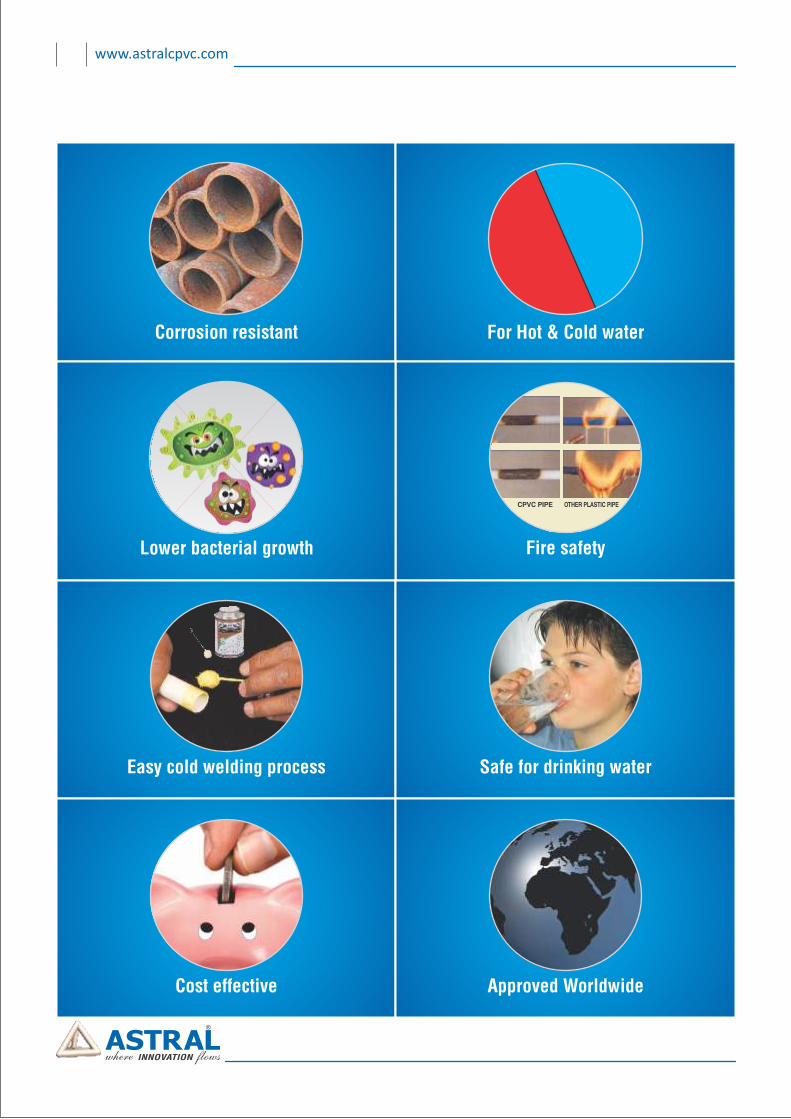
Corrosion resistant For Hot & Cold water
Safe for drinking water
Lower bacterial growth Fire safety
Easy cold welding process
Approved WorldwideCost effective
www.astralcpvc.com
FlowGuard™ is the registered mark of The Lubrizol Corporation.The Lubrizol Corporation is a Berkshire Hathaway company.
14 ................................................ 33Thermal Expansion & Contraction Thermal Expansion & Contraction
01 About Us ....................................................................................... 01
02 Standards & Specifications............................................................. 02
03 Why Flowguard™ Plus CPVC .......................................................... 03
04 Solvent Cement.............................................................................. 04
05 Certificates ..................................................................................... 05
06 Why ASTRAL Flowguard™ Plus CPVC ............................................. 07
07 Applications In Various Segments .................................................. 08
08 Basic Physical Properties................................................................ 09
09 Features & Benefits........................................................................ 10
10 Product Range................................................................................ 11
11 Technical Details ............................................................................ 27
12 Fluid Handling Characteristic Of ASTRAL Flowguard™ Plus Pipe.... 29
13 Fraction Loss & Flow Velocity ........................................................ 30
14 ................................................ 33Thermal Expansion & Contraction
15 Horizontal & Vertical Supports....................................................... 35
16 Underground Installation............................................................... 36
17 Requirement of Thermally Insulating CPVC Pipe ........................... 37
18 Joining ASTRAL CPVC Pipes & Fittings............................................ 38
19 How to Use Solvent Cement, Primer & Cleaner..............................39
20 Important Notes ............................................................................ 40
21 General Guideline For All Installations........................................... 41
22 Notes.............................................................................................. 42
www.astralcpvc.com
Index
01 www.astralcpvc.com
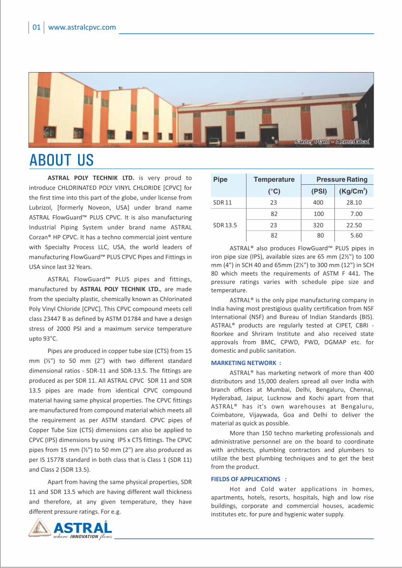
Santej Plant ‐ AhmedabadSantej Plant ‐ AhmedabadSantej Plant ‐ Ahmedabad
ASTRAL POLY TECHNIK LTD. is very proud to
introduce CHLORINATED POLY VINYL CHLORIDE [CPVC] for
the first time into this part of the globe, under license from
Lubrizol, [formerly Noveon, USA] under brand name
ASTRAL FlowGuard™ PLUS CPVC. It is also manufacturing
Industrial Piping System under brand name ASTRAL
Corzan® HP CPVC. It has a techno commercial joint venture
with Specialty Process LLC, USA, the world leaders of
manufacturing FlowGuard™ PLUS CPVC Pipes and Fittings in
USA since last 32 Years.
ASTRAL FlowGuard™ PLUS pipes and fittings,
manufactured by ASTRAL POLY TECHNIK LTD., are made
from the specialty plastic, chemically known as Chlorinated
Poly Vinyl Chloride [CPVC]. This CPVC compound meets cell
class 23447 B as defined by ASTM D1784 and have a design
stress of 2000 PSI and a maximum service temperature
upto 93°C.
Pipes are produced in copper tube size (CTS) from 15
mm (½") to 50 mm (2") with two different standard
dimensional ratios ‐ SDR‐11 and SDR‐13.5. The fittings are
produced as per SDR 11. All ASTRAL CPVC SDR 11 and SDR
13.5 pipes are made from identical CPVC compound
material having same physical properties. The CPVC fittings
are manufactured from compound material which meets all
the requirement as per ASTM standard. CPVC pipes of
Copper Tube Size (CTS) dimensions can also be applied to
CPVC (IPS) dimensions by using IPS x CTS fittings. The CPVC
pipes from 15 mm (½") to 50 mm (2") are also produced as
per IS 15778 standard in both class that is Class 1 (SDR 11)
and Class 2 (SDR 13.5).
Apart from having the same physical properties, SDR
11 and SDR 13.5 which are having different wall thickness
and therefore, at any given temperature, they have
different pressure ratings. For e.g.
ABOUT USPipe Temperature Pressure Rating
2 (°C) (PSI) (Kg/Cm )
SDR 11 23 400 28.10
82 100 7.00
SDR 13.5 23 320 22.50
82 80 5.60
ASTRAL® also produces FlowGuard™ PLUS pipes in iron pipe size (IPS), available sizes are 65 mm (2½") to 100 mm (4") in SCH 40 and 65mm (2½") to 300 mm (12") in SCH 80 which meets the requirements of ASTM F 441. The pressure ratings varies with schedule pipe size and temperature.
ASTRAL® is the only pipe manufacturing company in India having most prestigious quality certification from NSF International (NSF) and Bureau of Indian Standards (BIS). ASTRAL® products are regularly tested at CIPET, CBRI ‐ Roorkee and Shriram Institute and also received state approvals from BMC, CPWD, PWD, DGMAP etc. for domestic and public sanitation.
MARKETING NETWORK :
ASTRAL® has marketing network of more than 400 distributors and 15,000 dealers spread all over India with branch offices at Mumbai, Delhi, Bengaluru, Chennai, Hyderabad, Jaipur, Lucknow and Kochi apart from that ASTRAL® has it's own warehouses at Bengaluru, Coimbatore, Vijaywada, Goa and Delhi to deliver the material as quick as possible.
More than 150 techno marketing professionals and administrative personnel are on the board to coordinate with architects, plumbing contractors and plumbers to utilize the best plumbing techniques and to get the best from the product.
FIELDS OF APPLICATIONS :
Hot and Cold water applications in homes, apartments, hotels, resorts, hospitals, high and low rise buildings, corporate and commercial houses, academic institutes etc. for pure and hygienic water supply.
FlowGuard™ is the registered mark of The Lubrizol Corporation.The Lubrizol Corporation is a Berkshire Hathaway company.
02www.astralcpvc.com
ASTM D1784:
Standard Specification for Rigid Poly (Vinyl Chloride) (PVC) Compounds and Chlorinated Poly (Vinyl Chloride) (CPVC) Compounds.
ASTM D2846:
Specification for Chlorinated Poly (Vinyl Chloride) (CPVC) Plastic Hot & Cold water distribution systems.
ASTM F493:
Standard Specification for Solvent Cements for Chlorinated Poly (Vinyl Chloride) (CPVC) Plastic Pipe & Fittings.
ASTM F441:
Standard Specification for Chlorinated Poly (Vinyl Chloride) (CPVC) Plastic Pipe, SCH 40 & 80.
ASTM F438:
Socket‐Type Chlorinated Polyvinyl Chloride Plastic Pipe Fittings. SCH 40.
ASTM F439:
Socket‐Type Chlorinated Polyvinyl Chloride Plastic Pipe Fittings. SCH 80.
ASTM D2774:
Underground installation of Thermoplastic pipes.
IS 15778:
Chlorinated poly vinyl chloride (CPVC) pipe for potable hot & cold water distribution supplies.
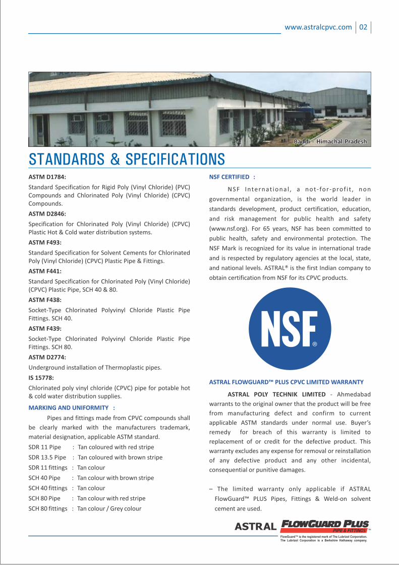
STANDARDS & SPECIFICATIONSNSF CERTIFIED :
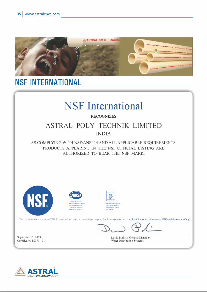
NSF Internat iona l , a not ‐ for ‐prof i t , non
governmental organization, is the world leader in
standards development, product certification, education,
and risk management for public health and safety
(www.nsf.org). For 65 years, NSF has been committed to
public health, safety and environmental protection. The
NSF Mark is recognized for its value in international trade
and is respected by regulatory agencies at the local, state,
and national levels. ASTRAL® is the first Indian company to
obtain certification from NSF for its CPVC products.
ASTRAL FLOWGUARD™ PLUS CPVC LIMITED WARRANTY
ASTRAL POLY TECHNIK LIMITED ‐ Ahmedabad
warrants to the original owner that the product will be free
from manufacturing defect and confirm to current
applicable ASTM standards under normal use. Buyer’s
remedy for breach of this warranty is limited to
replacement of or credit for the defective product. This
warranty excludes any expense for removal or reinstallation
of any defective product and any other incidental,
consequential or punitive damages.
– The limited warranty only applicable if ASTRAL
FlowGuard™ PLUS Pipes, Fittings & Weld‐on solvent
cement are used.
Baddi ‐ Himachal PradeshBaddi ‐ Himachal PradeshBaddi ‐ Himachal Pradesh
MARKING AND UNIFORMITY :
Pipes and fittings made from CPVC compounds shall
be clearly marked with the manufacturers trademark,
material designation, applicable ASTM standard.
SDR 11 Pipe : Tan coloured with red stripe
SDR 13.5 Pipe : Tan coloured with brown stripe
SDR 11 fittings : Tan colour
SCH 40 Pipe : Tan colour with brown stripe
SCH 40 fittings : Tan colour
SCH 80 Pipe : Tan colour with red stripe
SCH 80 fittings : Tan colour / Grey colour
03 www.astralcpvc.com
WHY FLOWGUARD™ PLUS CPVCWHY PIPE AND FITTINGS ARE THE BEST CHOICE™FOR HOT AND COLD POTABLE WATER DISTRIBUTION ?
• USA : NSF International• Germany : Deutscher Verein des Gas‐und Wasserfaches (DVGW)• UK : Water Research Council (WRC)• Canada : Canadian Standards Association (CSA)
APPROVALS ACROSS THE WORLD BYPROMINENT HEALTH AND STANDARDS ASSOCIATIONS
• Holland : Keurings instituut voor Water leiding artikelen (KIWA)• France : Center Scientifique et technique du batiment (CSTB)• Turkey : Turkish Standard Institution (TSE)
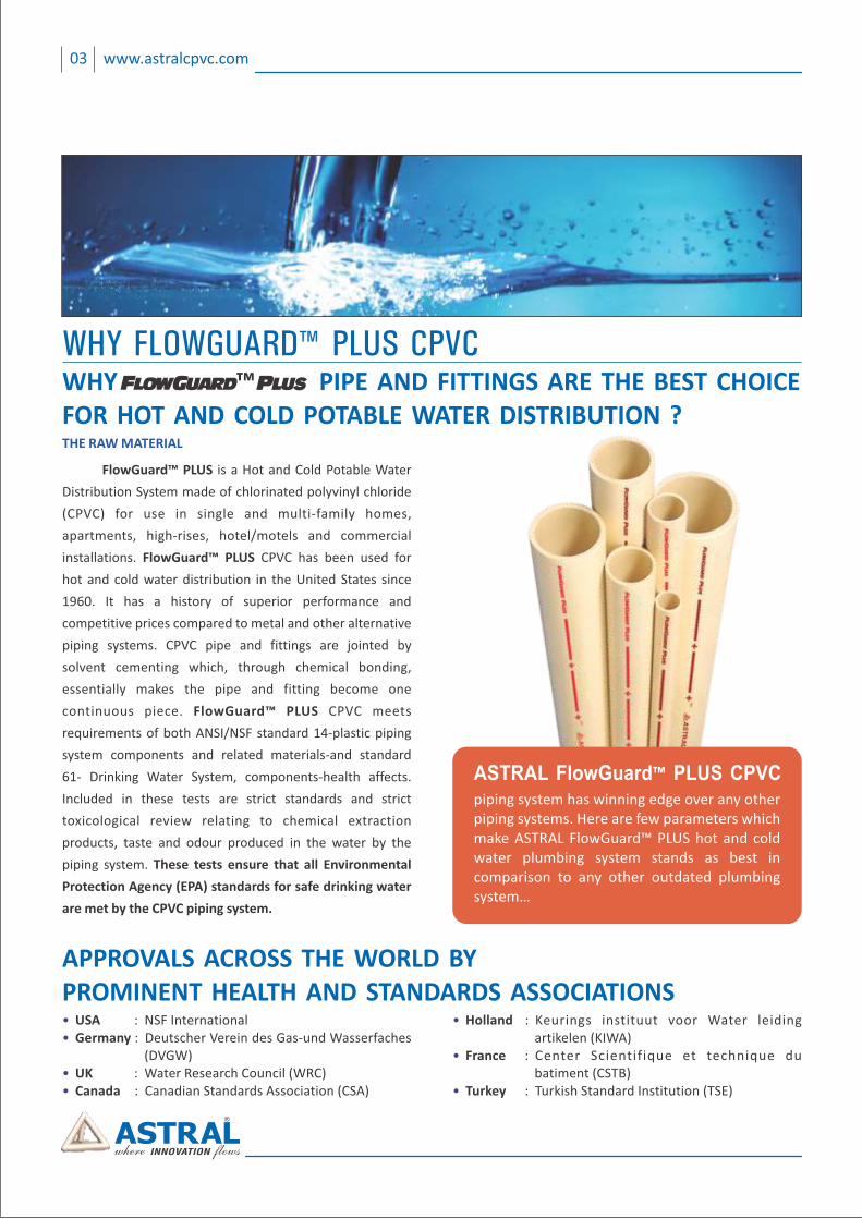
THE RAW MATERIAL
FlowGuard™ PLUS is a Hot and Cold Potable Water
Distribution System made of chlorinated polyvinyl chloride
(CPVC) for use in single and multi‐family homes,
apartments, high‐rises, hotel/motels and commercial
installations. FlowGuard™ CPVC has been used for PLUS
hot and cold water distribution in the United States since
1960. It has a history of superior performance and
competitive prices compared to metal and other alternative
piping systems. CPVC pipe and fittings are jointed by
solvent cementing which, through chemical bonding,
essentially makes the pipe and fitting become one
continuous piece. CPVC meets FlowGuard™ PLUS
requirements of both ANSI/NSF standard 14‐plastic piping
system components and related materials‐and standard
61‐ Drinking Water System, components‐health affects.
Included in these tests are strict standards and strict
toxicological review relating to chemical extraction
products, taste and odour produced in the water by the
piping system. These tests ensure that all Environmental
Protection Agency (EPA) standards for safe drinking water
are met by the CPVC piping system.
piping system has winning edge over any other piping systems. Here are few parameters which make ASTRAL FlowGuard™ PLUS hot and cold water plumbing system stands as best in comparison to any other outdated plumbing system…
ASTRAL FlowGuard™ PLUS CPVC
FlowGuard™ is the registered mark of The Lubrizol Corporation.The Lubrizol Corporation is a Berkshire Hathaway company.
04www.astralcpvc.com
Approved
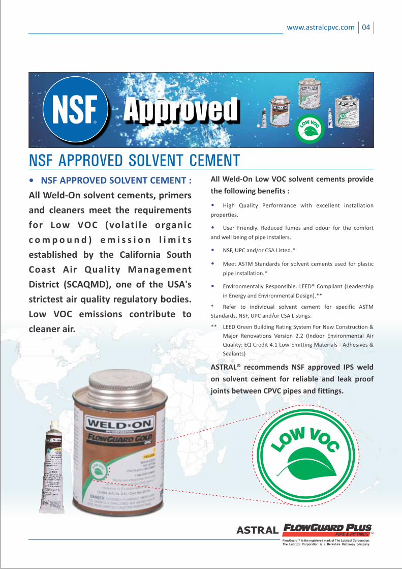
• NSF APPROVED SOLVENT CEMENT :
All Weld‐On solvent cements, primers
and cleaners meet the requirements
for Low VOC (volati le organic
c o m p o u n d ) e m i s s i o n l i m i t s
established by the California South
Coast Air Quality Management
District (SCAQMD), one of the USA's
strictest air quality regulatory bodies.
Low VOC emissions contribute to
cleaner air.
NSF APPROVED SOLVENT CEMENTAll Weld‐On Low VOC solvent cements provide
the following benefits :
• High Quality Performance with excellent installation
properties.
• User Friendly. Reduced fumes and odour for the comfort
and well being of pipe installers.
• NSF, UPC and/or CSA Listed.*
• Meet ASTM Standards for solvent cements used for plastic
pipe installation.*
• Environmentally Responsible. LEED® Compliant (Leadership
in Energy and Environmental Design).**
* Refer to individual solvent cement for specific ASTM
Standards, NSF, UPC and/or CSA Listings.
** LEED Green Building Rating System For New Construction &
Major Renovations Version 2.2 (Indoor Environmental Air
Quality: EQ Credit 4.1 Low‐Emitting Materials ‐ Adhesives &
Sealants)
ASTRAL® recommends NSF approved IPS weld
on solvent cement for reliable and leak proof
joints between CPVC pipes and fittings.
05 www.astralcpvc.com
NSF INTERNATIONAL

FlowGuard™ is the registered mark of The Lubrizol Corporation.The Lubrizol Corporation is a Berkshire Hathaway company.
0.00016132 0.00018361
Test report fromCentral Building Research Institute,
Roorkee
5.0 Conclusions & Recommendations
Based on generated data during experimental work, “Astral” brand CPVC pipes and fittings have been found suitable for hot and cold water supply in buildings.
“Astral” brand CPVC pipes and fittings meet the requirements of ASTM D 2846 (properties of pipes and fittings) IS: 10500-91 (quality of water) and IS: 10151-82 (overall migration of leachable additives).
Works has been carried out on the samples supplied by the party and the reported results are based on thees samples.
11/25
CBRI
06www.astralcpvc.com
CBRI-ROORKEE
07 www.astralcpvc.com
WHY ASTRAL CPVC?™
APPROVALS IN INDIA
• Bureau of Indian Standards Approval ‐ ISI marked
• NSF certificate for CPVC pipe & fittings (ASTRAL® ‐ The
only pipe manufacturing company in India now having
two most prestigious quality certifications from National
Sanitation Foundation and Bureau of Indian Standards.)
• State Approvals of CPVC System ‐ BMC, CPWD, PWD,
DGMAP etc.
• Tested in India regularly by CIPET, CBRI ‐ Roorkee,
Shriram Institute
• Apart from manufacturing and distributing world class
FlowGuard™ PLUS CPVC pipes and fittings, ASTRAL takes
care of its products by constantly testing and checking
CPVC pipes and fittings in their world class Quality
Assurance Laboratory, where various tests are carried
out at regular intervals to exceed the quality levels
beyond the industry standards.
ASTRAL® also takes care of its
customers by training plumbers and
plumbing contractors throughout
the year by updating them about
modern plumbing techniques and
to do plumbing work more effectively and professionally.
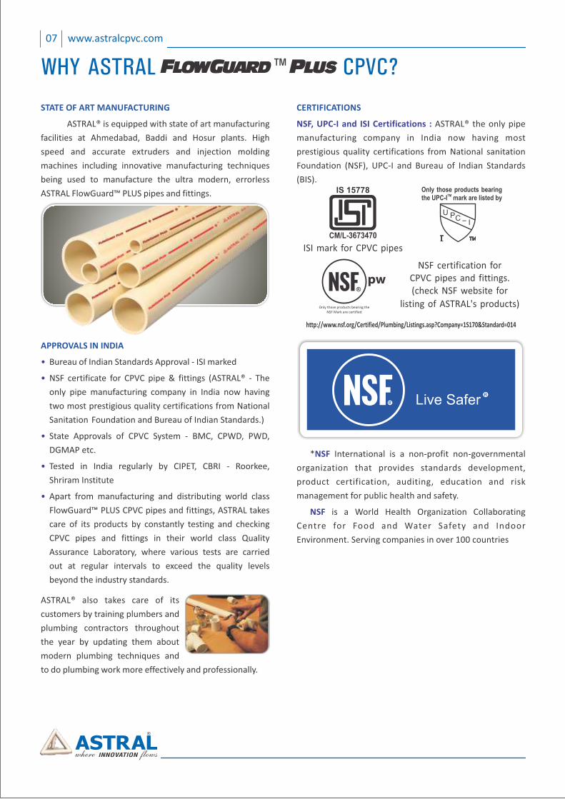
STATE OF ART MANUFACTURING
ASTRAL® is equipped with state of art manufacturing
facilities at Ahmedabad, Baddi and Hosur plants. High
speed and accurate extruders and injection molding
machines including innovative manufacturing techniques
being used to manufacture the ultra modern, errorless
ASTRAL FlowGuard™ PLUS pipes and fittings.
http://www.nsf.org/Certified/Plumbing/Listings.asp?Company=1S170&Standard=014
Live Safer
* International is a non‐profit non‐governmental NSF
organization that provides standards development,
product certification, auditing, education and risk
management for public health and safety.
is a World Health Organization Collaborating NSF
Centre for Food and Water Safety and Indoor
Environment. Serving companies in over 100 countries
CERTIFICATIONS
NSF, UPC‐I and ISI Certifications : ASTRAL® the only pipe
manufacturing company in India now having most
prestigious quality certifications from National sanitation
Foundation (NSF), UPC‐I and Bureau of Indian Standards
(BIS).
(check NSF website for
listing of ASTRAL's products)
NSF certification forCPVC pipes and fittings.pw
Only those products bearing theNSF Mark are certified
®
CM/L-3673470
IS 15778
ISI mark for CPVC pipes
FlowGuard™ is the registered mark of The Lubrizol Corporation.The Lubrizol Corporation is a Berkshire Hathaway company.
08www.astralcpvc.com
Educational Institutes
Residential Projects
Corporates
Hotels
Hospitals
APPLICATIONS IN VARIOUS SEGMENTS
09 www.astralcpvc.com
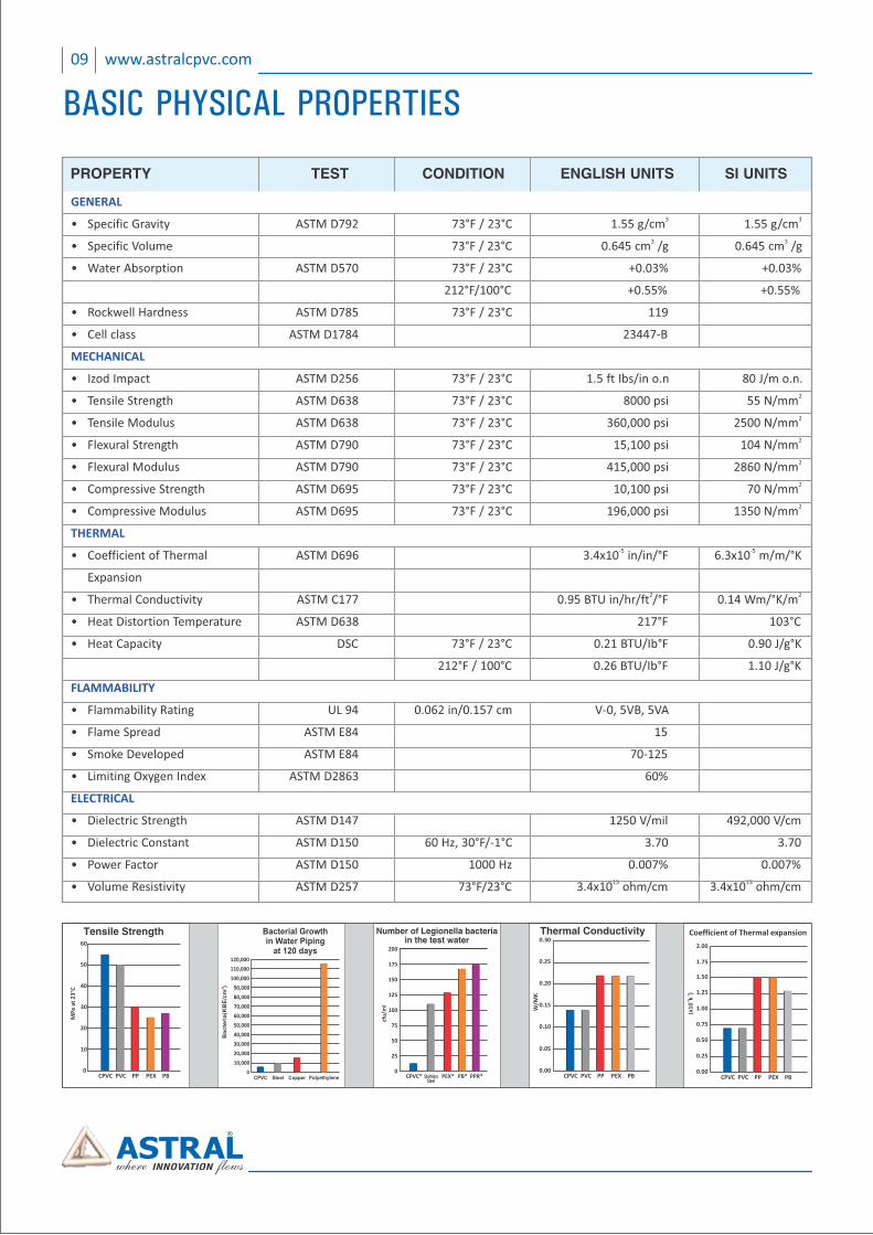
Number of Legionella bacteriain the test water
CPVC* StainlessSteel
PEX* PB* PPR*
cfu
/ml
200
175
150
125
100
75
50
25
0
0.05
0.00CPVC PVC PP PEX PB
Thermal Conductivity
W/M
K
0.10
0.15
0.20
0.25
0.30
0.25
0.00CPVC PVC PP PEX PB
Coefficient of Thermal expansion
‐4‐1
(x1
0k
)
0.50
0.75
1.00
1.75
2.00
1.25
1.50
GENERAL 3 3• Specific Gravity ASTM D792 73°F / 23°C 1.55 g/cm 1.55 g/cm
3 3• Specific Volume 73°F / 23°C 0.645 cm /g 0.645 cm /g
• Water Absorption ASTM D570 73°F / 23°C +0.03% +0.03%
212°F/100°C +0.55% +0.55%
• Rockwell Hardness ASTM D785 73°F / 23°C 119
• Cell class ASTM D1784 23447‐B
MECHANICAL
• Izod Impact ASTM D256 73°F / 23°C 1.5 ft Ibs/in o.n 80 J/m o.n.2• Tensile Strength ASTM D638 73°F / 23°C 8000 psi 55 N/mm2• Tensile Modulus ASTM D638 73°F / 23°C 360,000 psi 2500 N/mm2• Flexural Strength ASTM D790 73°F / 23°C 15,100 psi 104 N/mm2• Flexural Modulus ASTM D790 73°F / 23°C 415,000 psi 2860 N/mm2• Compressive Strength ASTM D695 73°F / 23°C 10,100 psi 70 N/mm2• Compressive Modulus ASTM D695 73°F / 23°C 196,000 psi 1350 N/mm
THERMAL ‐5 ‐5• Coefficient of Thermal ASTM D696 3.4x10 in/in/°F 6.3x10 m/m/°K
Expansion2 2• Thermal Conductivity ASTM C177 0.95 BTU in/hr/ft /°F 0.14 Wm/°K/m
• Heat Distortion Temperature ASTM D638 217°F 103°C
• Heat Capacity DSC 73°F / 23°C 0.21 BTU/Ib°F 0.90 J/g°K
212°F / 100°C 0.26 BTU/Ib°F 1.10 J/g°K
FLAMMABILITY
• Flammability Rating UL 94 0.062 in/0.157 cm V‐0, 5VB, 5VA
• Flame Spread ASTM E84 15
• Smoke Developed ASTM E84 70‐125
• Limiting Oxygen Index ASTM D2863 60%
ELECTRICAL
• Dielectric Strength ASTM D147 1250 V/mil 492,000 V/cm
• Dielectric Constant ASTM D150 60 Hz, 30°F/‐1°C 3.70 3.70
• Power Factor ASTM D150 1000 Hz 0.007% 0.007%15 15• Volume Resistivity ASTM D257 73°F/23°C 3.4x10 ohm/cm 3.4x10 ohm/cm
PROPERTY TEST CONDITION ENGLISH UNITS SI UNITS
BASIC PHYSICAL PROPERTIES
FlowGuard™ is the registered mark of The Lubrizol Corporation.The Lubrizol Corporation is a Berkshire Hathaway company.
10www.astralcpvc.com
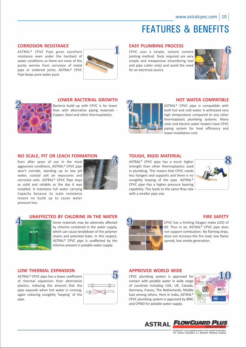
CORROSION RESISTANCEASTRAL® CPVC Pipe gives excellent resistance even under the harshest of water conditions so there are none of the purity worries from corrosion of metal pipe or soldered joints. ASTRAL® CPVC Pipe keeps pure water pure.
111
NO SCALE, PIT OR LEACH FORMATIONEven after years of use in the most aggressive conditions, ASTRAL® CPVC pipe won’t corrode, standing up to low pH water, coastal salt air exposures and corrosive soils. ASTRAL® CPVC Pipe stays as solid and reliable as the day it was installed. It maintains full water carrying Capacity because its scale resistance means no build up to cause water pressure loss.
333
LOWER BACTERIAL GROWTHBacteria build up with CPVC is far lower than with alternative piping materials ‐ Copper, Steel and other thermoplastics.
222
UNAFFECTED BY CHLORINE UNAFFECTED BY CHLORINE IN THE WATERIN THE WATERUNAFFECTED BY CHLORINE IN THE WATERSome materials may be adversely affected by chlorine contained in the water supply, which can cause breakdown of the polymer chains and potential leaks. In this respect, ASTRAL® CPVC pipe is unaffected by the chlorine present in potable water supply.
444
LOW THERMAL EXPANSIONASTRAL® CPVC pipe has a lower coefficient of thermal expansion than alternative plastics, reducing the amount that the pipe expands when hot water is running, again reducing unsightly ‘looping’ of the pipe.
555
EASY PLUMBING PROCESSEASY PLUMBING PROCESSEASY PLUMBING PROCESSCPVC uses a simple, solvent cement jointing method. Tools required are very simple and inexpensive (chamfering tool and pipe cutter only) and avoid the need for an electrical source.
666
TOUGH, RIGID MATERIALASTRAL® CPVC pipe has a much higher strength than other thermoplastics used in plumbing. This means that CPVC needs less hangers and supports and there is no unsightly looping of the pipe. ASTRAL® CPVC pipe Has a higher pressure bearing capability. This leads to the same flow rate with a smaller pipe size.
OTHERPLASTIC PIPE CPVC PIPE
888
HOT WATER COMPATIBLEHOT WATER COMPATIBLEHOT WATER COMPATIBLEASTRAL® CPVC pipe is compatible with both hot and cold water. It withstand very high temperature compared to any other thermoplastic plumbing systems. Many solar and electric water heaters have CPVC piping system for heat efficiency and lower installation cost.
777
FIRE SAFETYCPVC has a limiting Oxygen Index (LOI) of 60. Thus in air, ASTRAL® CPVC pipe does not support combustion. No flaming drips, does not increase the fire load, low flame spread, low smoke generation.
OTHERPLASTIC PIPECPVC PIPE
999
pw
Only those products bearing theNSF Mark are certified
(check NSF website forlisting of ASTRAL'S products)
NSF certification forCPVC pipes and fittings.
CM/L-3673470
IS 15778
ISI mark for CPVC pipes
®ASTRAL now have
Live Safer
APPROVED WORLD WIDECPVC plumbing system is approved for contact with potable water in wide range of countries including USA, UK, Canada, Germany, France, The Netherlands, Middle East among others. Here in India, ASTRAL® CPVC plumbing system is approved by BMC and CPWD for potable water supply.
101010
FEATURES & BENEFITS
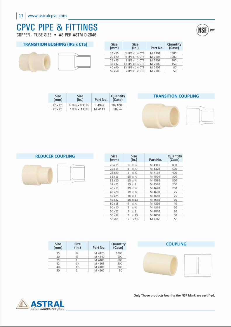
COPPER - TUBE SIZE • AS PER ASTM D-2846pw
Only Those products bearing the NSF Mark are certified.
Size Size Quantity (mm) (In.) Part No. (Case)
20 x 15 ¾ x ½ M 4341 800 25 x 15 1 x ½ M 4420 500 25 x 20 1 x ¾ M 4134 400 32 x 15 1¼ x ½ M 4520 300 32 x 20 ¾ M 4530 3001¼ x 32 x 25 1¼ x 1 M 4540 200 40 x 15 1½ x ½ M 4620 200 40 x 20 1½ x ¾ M 4630 75 40 x 25 1½ x 1 M 4640 75 40 x 32 1½ x 1¼ M 4650 50 50 x 15 2 x ½ M 4820 40 50 x 20 2 x ¾ M 4830 50 50 x 25 2 x 1 M 4840 30 50 x 32 2 x 1¼ M 4850 30 50 x40 2 x 1½ M 4860 50
REDUCER COUPLING
15 x 15 ½ IPS x ½ CTS M 2902 1500 20 x 20 ¾ IPS x ¾ CTS M 2903 1000 25 x 25 1 IPS x 1 CTS M 2904 200 32 x 32 1¼ IPS x 1¼ CTS M 2905 150 40 x 40 1½ IPS x 1½ CTS M 2906 80 50 x 50 2 IPS x 2 CTS M 2908 50
Size Size Quantity (mm) (In.) Part No. (Case)
TRANSITION BUSHING (IPS x CTS)
Size Size Quantity (mm) (In.) Part No. (Case)
15 ½ M 4120 1200 20 ¾ M 4340 600 25 1 M 4100 600 32 1¼ M 4105 300 40 1½ M 4106 200 50 2 M 4200 50
COUPLING
Size Size Quantity (mm) (In.) Part No. (Case)
20 x 20 ¾ IPS x ¾ CTS T 4342 10 / 100
25 x 25 1 IPS x 1 CTS M 4111 50 / ---
TRANSITION COUPLING
11 www.astralcpvc.com
CPVC PIPE & FITTINGS
FlowGuard™ is the registered mark of The Lubrizol Corporation.The Lubrizol Corporation is a Berkshire Hathaway company.
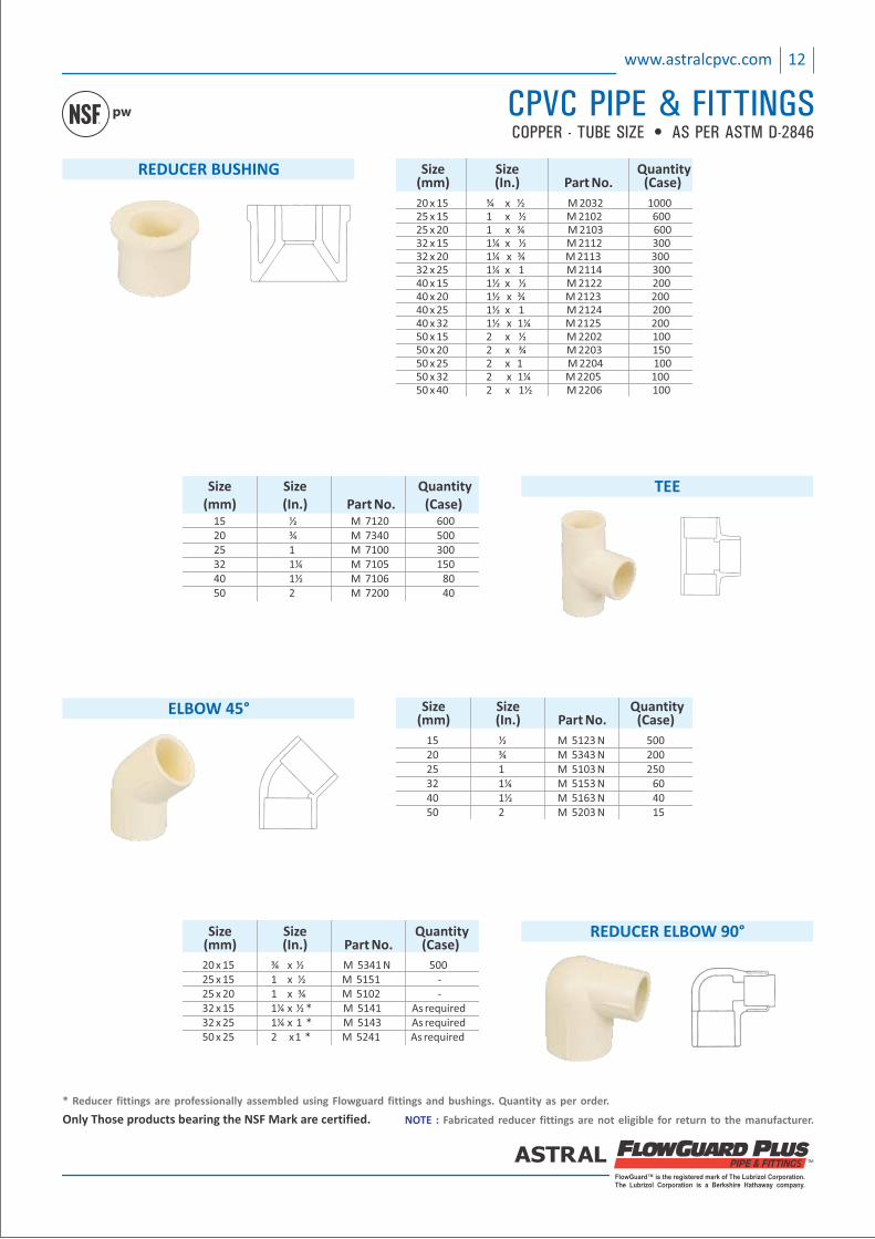
Only Those products bearing the NSF Mark are certified. Fabricated reducer fittings are not eligible for return to the manufacturer.NOTE :
* Reducer fittings are professionally assembled using Flowguard fittings and bushings. Quantity as per order.
12www.astralcpvc.com
CPVC PIPE & FITTINGSCOPPER - TUBE SIZE • AS PER ASTM D-2846
pw
REDUCER BUSHING
20 x 15 ¾ x ½ M 2032 1000 25 x 15 1 x ½ M 2102 600 25 x 20 1 x ¾ M 2103 600 32 x 15 1¼ x ½ M 2112 300 32 x 20 1¼ x ¾ M 2113 300 32 x 25 1¼ x 1 M 2114 300 40 x 15 1½ x ½ M 2122 200 40 x 20 1½ x ¾ M 2123 200 40 x 25 1½ x 1 M 2124 200 40 x 32 1½ x 1¼ M 2125 200 50 x 15 2 x ½ M 2202 100 50 x 20 2 x ¾ M 2203 150 50 x 25 2 x 1 M 2204 100 50 x 32 2 x 1¼ M 2205 100 50 x 40 2 x 1½ M 2206 100
Size Size Quantity (mm) (In.) Part No. (Case)
15 ½ M 5123 N 500 20 ¾ M 5343 N 200 25 1 M 5103 N 250 32 1¼ M 5153 N 60 40 1½ M 5163 N 40 50 2 M 5203 N 15
Size Size Quantity (mm) (In.) Part No. (Case)
ELBOW 45°
15 ½ M 7120 600 20 ¾ M 7340 500 25 1 M 7100 300 32 1¼ M 7105 150 40 1½ M 7106 80 50 2 M 7200 40
Size Size Quantity (mm) (In.) Part No. (Case)
TEE
Size Size Quantity (mm) (In.) Part No. (Case)
20 x 15 ¾ x ½ M 5341 N 500 25 x 15 1 x ½ M 5151 ‐ 25 x 20 1 x ¾ M 5102 ‐ 32 x 15 1 x ¼ ½ * M 5141 As required 32 x 25 1 x ¼ 1 * M 5143 As required 50 x 25 2 x 1 * M 5241 As required
REDUCER ELBOW 90°
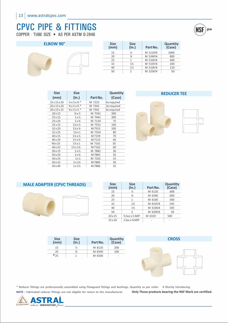
COPPER - TUBE SIZE • AS PER ASTM D-2846pw
13 www.astralcpvc.com
CPVC PIPE & FITTINGS
REDUCER TEE Size Size Quantity (mm) (In.) Part No. (Case) 15 x 15 x 20 ½ x ½ x ¾ * M 7223 As required 20 x 15 x 20 ¾ x ½ x ¾ * M 7343 As required 20 x 15 x 15 ¾ x ½ x ½ * M 7342 As required 20 x 15 ¾ x ½ M 7341 300 25 x 15 1 x ½ M 7442 300 25 x 20 1 x ¾ M 7134 75 32 x 15 1¼ x ½ M 7552 100 32 x 20 1¼ x ¾ M 7553 100 32 x 25 1¼ x 1 M 7554 80 40 x 15 1½ x ½ M 7159 70 40 x 20 1½ x ¾ M 7123 60 40 x 25 1½ x 1 M 7161 30 40 x 32 1½ x 1¼ M 7162 60 50 x 15 2 x ½ M 7882 30 50 x 20 2 x ¾ M 7883 35 50 x 25 2 x 1 M 7201 15 50 x 32 2 x 1¼ M 7885 30 50 x 40 2 x 1½ M 7886 25
CROSS Size Size Quantity (mm) (In.) Part No. (Case)
15 ½ M 8120 200
20 ¾ M 8340 100
25 1 M 8100 ‐#
Only Those products bearing the NSF Mark are certified. Fabricated reducer fittings are not eligible for return to the manufacturer.NOTE :
* Reducer fittings are professionally assembled using Flowguard fittings and bushings. Quantity as per order. # Shortly Introducing
ELBOW 90°
15 ½ M 5120 N 1000 20 ¾ M 5340 N 800 25 1 M 5100 N 400 32 1¼ M 5105 N 200 40 1½ M 5106 N 120 50 2 M 5200 N 50
Size Size Quantity (mm) (In.) Part No. (Case)
MALE ADAPTER (CPVC THREADS)
15 ½ M 6120 600
20 ¾ M 6340 600
25 1 M 6100 300
32 1¼ M 6105 B 150
40 1½ M 6106 B 100
50 2 M 6200 B 50
20 x 15 ¾ Soc x ½ MIP M 6320 500
25 x 20 1 Soc x ¾ MIP ‐ ‐
Size Size Quantity (mm) (In.) Part No. (Case)
FlowGuard™ is the registered mark of The Lubrizol Corporation.The Lubrizol Corporation is a Berkshire Hathaway company.
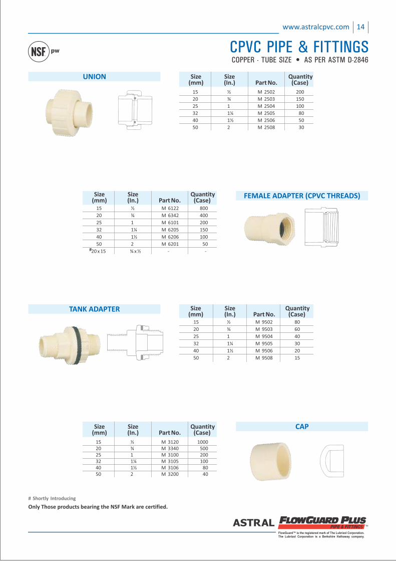
FEMALE ADAPTER (CPVC THREADS)
15 ½ M 6122 800
20 ¾ M 6342 400
25 1 M 6101 200
32 1¼ M 6205 150
40 1½ M 6206 100
50 2 M 6201 50
20 x 15 ¾ x ½ ‐ ‐
Size Size Quantity (mm) (In.) Part No. (Case)
#
TANK ADAPTER
15 ½ M 9502 80
20 ¾ M 9503 60
25 1 M 9504 40
32 1¼ M 9505 30
40 1½ M 9506 20
50 2 M 9508 15
Size Size Quantity (mm) (In.) Part No. (Case)
UNION
15 ½ M 2502 200
20 ¾ M 2503 150
25 1 M 2504 100
32 1¼ M 2505 80
40 1½ M 2506 50
50 2 M 2508 30
Size Size Quantity (mm) (In.) Part No. (Case)
CAP Size Size Quantity (mm) (In.) Part No. (Case)
15 ½ M 3120 1000 20 ¾ M 3340 500 25 1 M 3100 200 32 1¼ M 3105 100 40 1½ M 3106 80 50 2 M 3200 40
14www.astralcpvc.com
CPVC PIPE & FITTINGSCOPPER - TUBE SIZE • AS PER ASTM D-2846
pw
Only Those products bearing the NSF Mark are certified.
# Shortly Introducing
15 www.astralcpvc.com
# Shortly Introducing
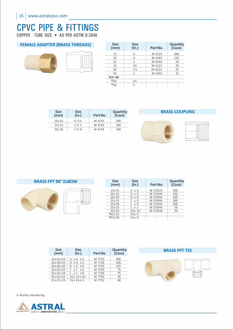
BRASS COUPLING Size Size Quantity (mm) (In.) Part No. (Case)
20 x 15 ¾ X ½ M 4732 200
25 x 15 1 X ½ M 4742 100
25 x 20 1 X ¾ M 4734 100
FEMALE ADAPTER (BRASS THREADS) Size Size Quantity (mm) (In.) Part No. (Case)
15 ½ M 6123 200 20 ¾ M 6343 150 25 1 M 6103 50 32 1¼ M 6113 25 40 1 ½ M 6153 25 50 2 M 6203 15 SCH ‐ 80 65 2½ ‐ ‐ 80 3 ‐ ‐
#
#
COPPER - TUBE SIZE • AS PER ASTM D-2846
CPVC PIPE & FITTINGS
BRASS FPT 90° ELBOW Size Size Quantity (mm) (In.) Part No. (Case)
15 x 15 ½ x ½ M 5702 N 200 20 x 15 ¾ x ½ M 5730 N 150 20 x 20 ¾ x ¾ M 5703 N 100 25 x 15 1 x ½ M 5740 N 100 25 x 20 1 x ¾ M 5734 N 100 25 x 25 1 x 1 M 5704 N 50 32 x 32 1¼ x 1¼ M 5705 N 30 32 x 15 1¼ x ½ ‐ ‐ 32 x 20 1¼ x ¾ ‐ ‐
##
BRASS FPT TEE Size Size Quantity (mm) (In.) Part No. (Case)
15 x 15 x 15 ½ x ½ x ½ M 7722 200 20 x 20 x 15 ¾ x ¾ x ½ M 7732 100 20 x 20 x 20 ¾ x ¾ x ¾ M 7733 125 25 x 25 x 15 1 x 1 x ½ M 7742 75 25 x 25 x 20 1 x 1 x ¾ M 7734 75 32 x 32 x 32 1¼ x 1¼ x 1¼ M 7755 30 32 x 32 x 15 1¼ x 1¼ x ½ M 7752 40
FlowGuard™ is the registered mark of The Lubrizol Corporation.The Lubrizol Corporation is a Berkshire Hathaway company.
16www.astralcpvc.com
CPVC PIPE & FITTINGSCOPPER - TUBE SIZE • AS PER ASTM D-2846
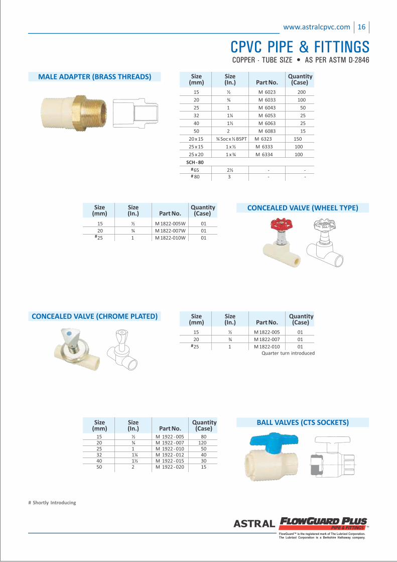
MALE ADAPTER (BRASS THREADS)
15 ½ M 6023 200
20 ¾ M 6033 100
25 1 M 6043 50
32 1¼ M 6053 25
40 1½ M 6063 25
50 2 M 6083 15
20 x 15 ¾ Soc x ½ BSPT M 6323 150
25 x 15 1 x ½ M 6333 100
25 x 20 1 x M 6334 100¾
SCH ‐ 80
65 2½ ‐ ‐ 80 3 ‐ ‐
Size Size Quantity (mm) (In.) Part No. (Case)
#
#
BALL VALVES (CTS SOCKETS) Size Size Quantity (mm) (In.) Part No. (Case) 15 ½ M 1922 ‐ 005 80 20 ¾ M 1922 ‐ 007 120 25 1 M 1922 ‐ 010 50 32 1¼ M 1922 ‐ 012 40 40 1½ M 1922 ‐ 015 30 50 2 M 1922 ‐ 020 15
CONCEALED VALVE (WHEEL TYPE) Size Size Quantity (mm) (In.) Part No. (Case)
15 ½ M 1822‐005W 01
20 ¾ M 1822‐007W 01
25 1 M 1822‐010W 01#
CONCEALED VALVE (CHROME PLATED) Size Size Quantity (mm) (In.) Part No. (Case)
15 ½ M 1822‐005 01
20 ¾ M 1822‐007 01
25 1 M 1822‐010 01#
Quarter turn introduced
# Shortly Introducing
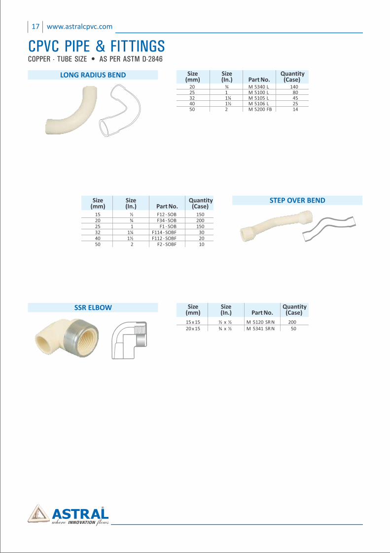
STEP OVER BEND Size Size Quantity (mm) (In.) Part No. (Case) 15 ½ F12 ‐ SOB 150 20 ¾ F34 ‐ SOB 200 25 1 F1 ‐ SOB 150 32 1¼ F114 ‐ SOBF 30 40 1½ F112 ‐ SOBF 20 50 2 F2 ‐ SOBF 10
SSR ELBOW Size Size Quantity (mm) (In.) Part No. (Case)
15 x 15 ½ x ½ M 5120 SR N 200 20 x 15 ¾ x ½ M 5341 SR N 50
20 ¾ M 5340 L 140 25 1 M 5100 L 80 32 1¼ M 5105 L 45 40 1½ M 5106 L 25 50 M 5200 FB2 14
Size Size Quantity (mm) (In.) Part No. (Case)
LONG RADIUS BEND
COPPER - TUBE SIZE • AS PER ASTM D-2846
17 www.astralcpvc.com
CPVC PIPE & FITTINGS
FlowGuard™ is the registered mark of The Lubrizol Corporation.The Lubrizol Corporation is a Berkshire Hathaway company.
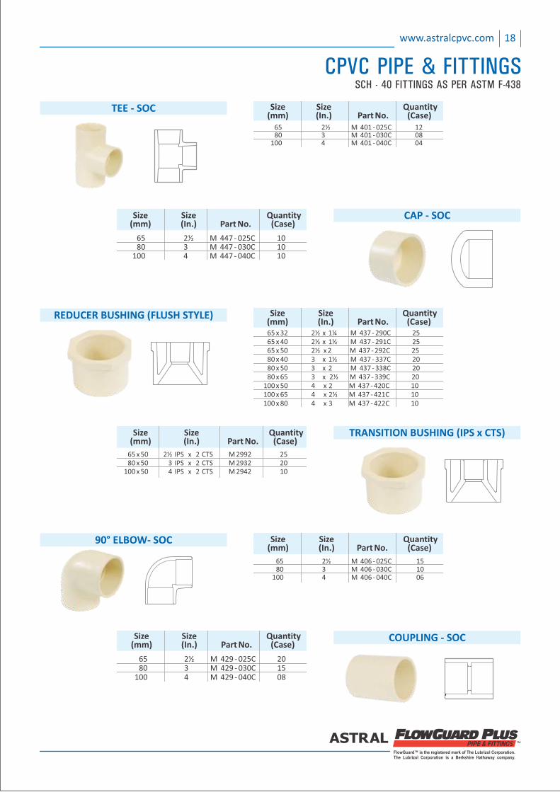
CAP ‐ SOC Size Size Quantity (mm) (In.) Part No. (Case)
65 2½ M 447 ‐ 025C 10 80 3 M 447 ‐ 030C 10 100 4 M 447 ‐ 040C 10
REDUCER BUSHING (FLUSH STYLE)
65 x 32 2½ x 1¼ M 437 ‐ 290C 25 65 x 40 2½ x 1½ M 437 ‐ 291C 25 65 x 50 2½ x 2 M 437 ‐ 292C 25 80 x 40 3 x 1½ M 437 ‐ 337C 20 80 x 50 3 x 2 M 437 ‐ 338C 20 80 x 65 3 x 2½ M 437 ‐ 339C 20 100 x 50 4 x 2 M 437 ‐ 420C 10 100 x 65 4 x 2½ M 437 ‐ 421C 10 100 x 80 4 x 3 M 437 ‐ 422C 10
Size Size Quantity (mm) (In.) Part No. (Case)
90° ELBOW‐ SOC Size Size Quantity (mm) (In.) Part No. (Case)
65 2½ M 406 ‐ 025C 15 80 3 M 406 ‐ 030C 10 100 4 M 406 ‐ 040C 06
COUPLING ‐ SOC
65 2½ M 429 ‐ 025C 20 80 3 M 429 ‐ 030C 15 100 4 M 429 ‐ 040C 08
Size Size Quantity (mm) (In.) Part No. (Case)
TEE ‐ SOC Size Size Quantity (mm) (In.) Part No. (Case) 65 2½ M 401 ‐ 025C 12 80 3 M 401 ‐ 030C 08 100 4 M 401 ‐ 040C 04
18www.astralcpvc.com
CPVC PIPE & FITTINGSSCH - 40 FITTINGS AS PER ASTM F-438
65 x 50 2½ IPS x 2 CTS M 2992 25 80 x 50 3 IPS x 2 CTS M 2932 20 100 x 50 4 IPS x 2 CTS M 2942 10
Size Size Quantity (mm) (In.) Part No. (Case)
TRANSITION BUSHING (IPS x CTS)
SCH - 80 FITTINGS AS PER ASTM F - 439
19 www.astralcpvc.com
CPVC PIPE & FITTINGS
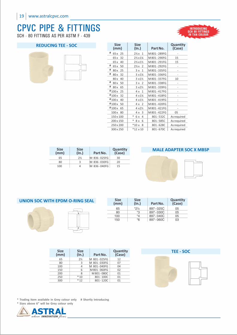
TEE ‐ SOC Size Size Quantity (mm) (In.) Part No. (Case) 65 2½ M 801 ‐ 025FG 12 80 3 M 801 ‐ 030FG 07 100 4 M 801 ‐ 040FG 04 150 6 M 801 ‐ 060FG 02 200 8 M 801 ‐ 080C 01 250 * 10 801 ‐ 100C 01 300 * 12 801 ‐ 120C 01
UNION SOC WITH EPDM O‐RING SEAL Size Size Quantity (mm) (In.) Part No. (Case) 65 *2½ 897 - 025C 05 80 *3 897 - 030C 05 100 *4 897 - 040C 05 150 *6 897 - 060C 03
MALE ADAPTER SOC X MBSP Size Size Quantity (mm) (In.) Part No. (Case)
65 2½ M 836 ‐ 025FG 30
80 3 M 836 ‐ 030FG 20
100 4 M 836 ‐ 040FG 15
REDUCING TEE ‐ SOC Size Size Quantity (mm) (In.) Part No. (Case)
65 x 25 2½ M 801 ‐ 289FG ‐ x 1
65 x 32 2½ M 801 ‐ 290FG 15 x 1¼
65 x 40 2½ M 801 ‐ 291FG 15 x 1½
65 x 50 2½ x 2 M 801 ‐ 292FG ‐
80 x 25 3 x 1 M 801 ‐ 335FG ‐
80 x 32 3 x 1¼ M 801 ‐ 336FG ‐
80 x 40 3 x 1½ M 801 ‐ 337FG 10
80 x 50 3 x 2 M 801 ‐ 338FG ‐
80 x 65 3 x 2½ M 801 ‐ 339FG ‐
100 x 25 4 x 1 M 801 ‐ 417FG ‐
100 x 32 4 x 1¼ M 801 ‐ 418FG ‐
100 x 40 4 x 1½ M 801 ‐ 419FG ‐
100 x 50 4 x 2 801 ‐ 420FG ‐M
100 x 65 4 x 2½ M 801 ‐ 421FG ‐
100 x 80 4 x 3 801 ‐ 422FG 05 M
150 x 100 * 6 x 4 801 ‐ 532C As required
200 x 150 * 8 x 6 801 ‐ 585C As required
250 x 200 * 10 x 8 801 ‐ 628C As required
300 x 250 * 12 x 10 801 ‐ 670C As required
#
#
#
#
#
#
#
#
#
#
#
INTRODUCINGSCH 80 FITTINGSIN TAN COLOUR
* Trading Item available in Grey colour only # Shortly Introducing* Sizes above 6” will be Grey colour only
FlowGuard™ is the registered mark of The Lubrizol Corporation.The Lubrizol Corporation is a Berkshire Hathaway company.
20www.astralcpvc.com
CPVC PIPE & FITTINGSSCH - 80 FITTINGS AS PER ASTM F - 439
* Trading Item available in Grey colour only # Shortly Introducing* Sizes above 6” will be Grey colour only
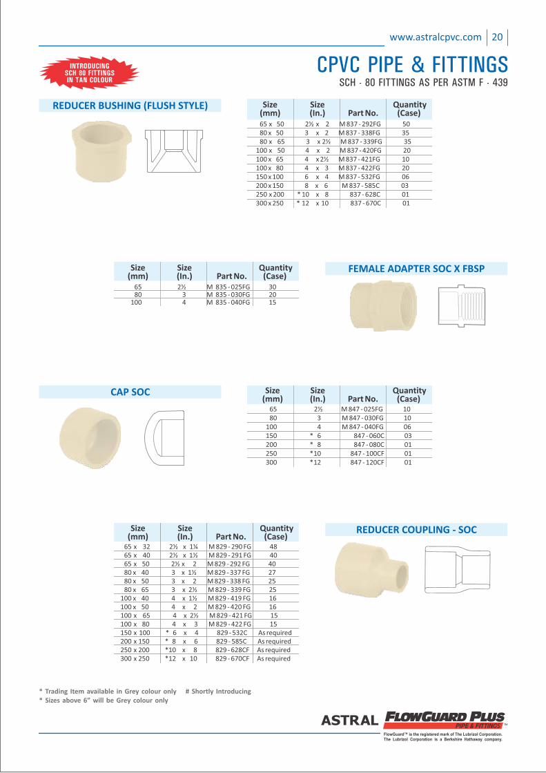
REDUCER COUPLING ‐ SOC Size Size Quantity (mm) (In.) Part No. (Case) 65 x 32 M 829 ‐ 290 FG 482½ x 1¼ 65 x 40 M 829 ‐ 291 402½ x 1½ FG 6 x 50 25 ½ x 2 M 829 ‐ 292 FG 40 80 x 40 3 x 1½ M 829 ‐ 337 27FG 80 x 50 3 x 2 M 829 ‐ 338 25FG 80 x 65 3 x 2½ M 829 ‐ 339 25FG 100 x 40 4 x M 829 ‐ 419 161½ FG 100 x 50 4 x 2 M 829 ‐ 420 16 FG 100 x 65 4 x 2½ M 829 ‐ 421 FG 15 100 x 80 4 x 3 M 829 ‐ 422 15FG 150 x 100 * 6 x 4 829 ‐ 532C As required 200 x 150 * 8 x 6 829 ‐ 585C As required 250 x 200 * 10 x 8 829 ‐ 628CF As required 300 x 250 * 12 x 10 829 ‐ 670CF As required
CAP SOC Size Size Quantity (mm) (In.) Part No. (Case) 65 2½ M 847 ‐ 025FG 10 80 3 M 847 ‐ 030FG 10 100 4 M 847 ‐ 040FG 06 150 * 6 847 ‐ 060C 03 200 * 8 847 ‐ 080C 01 250 * 10 847 ‐ 100CF 01 300 * 12 847 ‐ 120CF 01
FEMALE ADAPTER SOC X FBSP Size Size Quantity (mm) (In.) Part No. (Case) 65 2½ M 835 ‐ 025FG 30 80 3 M 835 ‐ 030FG 20 100 4 M 835 ‐ 040FG 15
REDUCER BUSHING (FLUSH STYLE) Size Size Quantity (mm) (In.) Part No. (Case)
65 x 50 2½ x 2 M 837 ‐ 292 50FG 80 x 50 3 x 2 M 837 ‐ 338 FG 35 80 x 65 3 x 2½ M 837 ‐ 339FG 35 100 x 50 4 x 2 M 837 ‐ 420FG 20 100 x 65 4 x 2½ M 837 ‐ 421FG 10 100 x 80 4 x 3 M 837 ‐ 422FG 20 150 x 100 6 x 4 M 837 ‐ 532FG 06 200 x 150 8 x 6 M 837 ‐ 585C 03 250 x 200 * 10 x 8 837 ‐ 628C 01 300 x 250 * 12 x 10 837 ‐ 670C 01
INTRODUCINGSCH 80 FITTINGSIN TAN COLOUR
SCH - 80 FITTINGS AS PER ASTM F - 439
21 www.astralcpvc.com
CPVC PIPE & FITTINGS
* Trading Item available in Grey colour only* Sizes above 6” will be Grey colour only
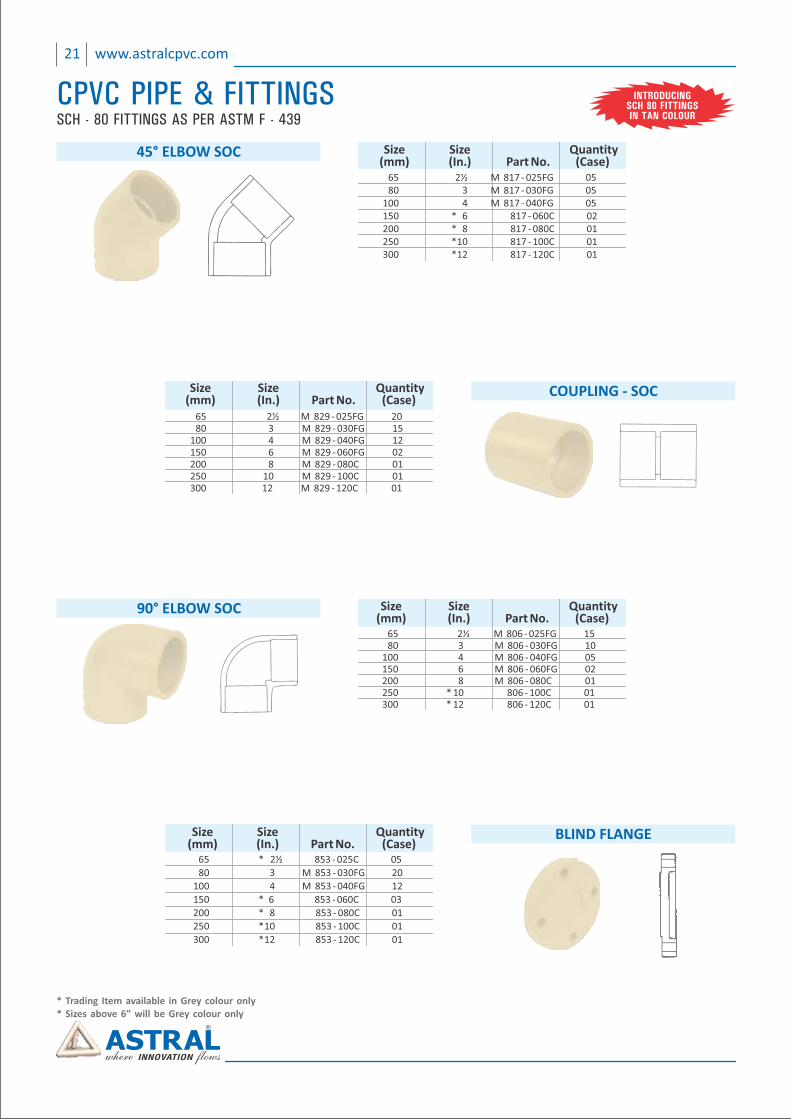
BLIND FLANGE Size Size Quantity (mm) (In.) Part No. (Case) 65 * 2½ 853 ‐ 025C 05
80 3 M 853 ‐ 030FG 20
100 4 M 853 ‐ 040FG 12
150 * 6 853 ‐ 060C 03
200 * 8 853 ‐ 080C 01
250 * 10 853 ‐ 100C 01
300 * 12 853 ‐ 120C 01
90° ELBOW SOC Size Size Quantity (mm) (In.) Part No. (Case) 65 2½ M 806 ‐ 025FG 15 80 3 M 806 ‐ 030FG 10 100 4 M 806 ‐ 040FG 05 150 6 M 806 ‐ 060FG 02 200 8 M 806 ‐ 080C 01 250 * 10 806 ‐ 100C 01 300 * 12 806 ‐ 120C 01
COUPLING ‐ SOC Size Size Quantity (mm) (In.) Part No. (Case) 65 2½ M 829 ‐ 025FG 20 80 3 M 829 ‐ 030FG 15 100 4 M 829 ‐ 040FG 12 150 6 M 829 ‐ 060FG 02 200 8 M 829 ‐ 080C 01 250 10 M 829 ‐ 100C 01 300 12 M 829 ‐ 120C 01
45° ELBOW SOC Size Size Quantity (mm) (In.) Part No. (Case) 65 2½ M 817 ‐ 025FG 05 80 3 M 817 ‐ 030FG 05 100 4 M 817 ‐ 040FG 05 150 * 6 817 ‐ 060C 02 200 * 8 817 ‐ 080C 01 250 * 10 817 ‐ 100C 01 300 * 12 817 ‐ 120C 01
INTRODUCINGSCH 80 FITTINGSIN TAN COLOUR
FlowGuard™ is the registered mark of The Lubrizol Corporation.The Lubrizol Corporation is a Berkshire Hathaway company.
22www.astralcpvc.com
CPVC PIPE & FITTINGSSCH - 80 FITTINGS AS PER ASTM F - 439
* Trading Item available in Grey colour only* Sizes above 6” will be Grey colour only
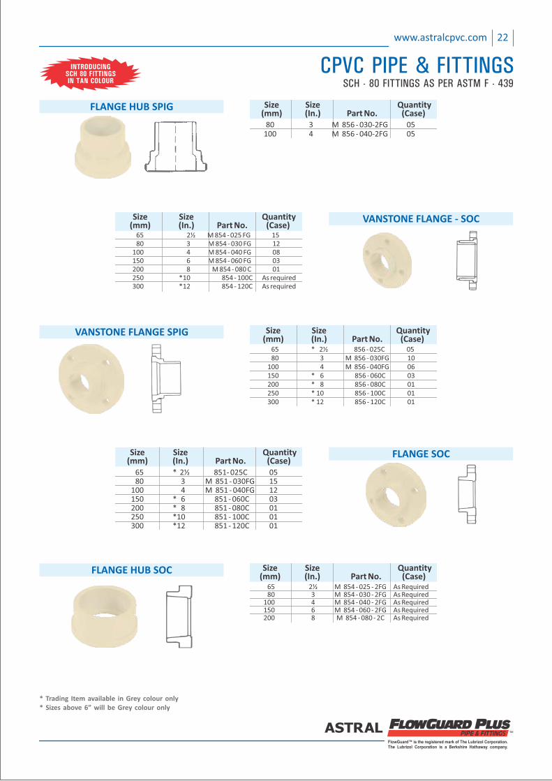
FLANGE SOC Size Size Quantity (mm) (In.) Part No. (Case) 65 * 2½ 851‐ 025C 05 80 3 M 851 ‐ 030FG 15 100 4 M 851 ‐ 040FG 12 150 * 6 851 ‐ 060C 03 200 * 8 851 ‐ 080C 01 250 * 10 851 ‐ 100C 01 300 * 12 851 ‐ 120C 01
Size Size Quantity (mm) (In.) Part No. (Case) 65 2½ M 854 ‐ 025 ‐ 2FG As Required 80 3 M 854 ‐ 030 ‐ 2FG As Required 100 4 M 854 ‐ 040 ‐ 2FG As Required 150 6 M 854 ‐ 060 ‐ 2FG As Required 200 8 M 854 ‐ 080 ‐ 2C As Required
FLANGE HUB SOC
VANSTONE FLANGE SPIG Size Size Quantity (mm) (In.) Part No. (Case) 65 * 2½ 856 ‐ 025C 05 80 3 M 856 ‐ 030FG 10 100 4 M 856 ‐ 040FG 06 150 * 6 856 ‐ 060C 03 200 * 8 856 ‐ 080C 01 250 * 10 856 ‐ 100C 01 300 * 12 856 ‐ 120C 01
VANSTONE FLANGE ‐ SOC
65 2½ M 854 ‐ 025 FG 15 80 3 M 854 ‐ 030 FG 12 100 4 M 854 ‐ 040 FG 08 150 6 M 854 ‐ 060 FG 03 200 8 M 854 ‐ 080 C 01 250 * 10 854 ‐ 100C As required 300 * 12 854 ‐ 120C As required
Size Size Quantity (mm) (In.) Part No. (Case)
FLANGE HUB SPIG Size Size Quantity (mm) (In.) Part No. (Case) 80 3 M 856 ‐ 030‐2FG 05 100 4 M 856 ‐ 040‐2FG 05
INTRODUCINGSCH 80 FITTINGSIN TAN COLOUR
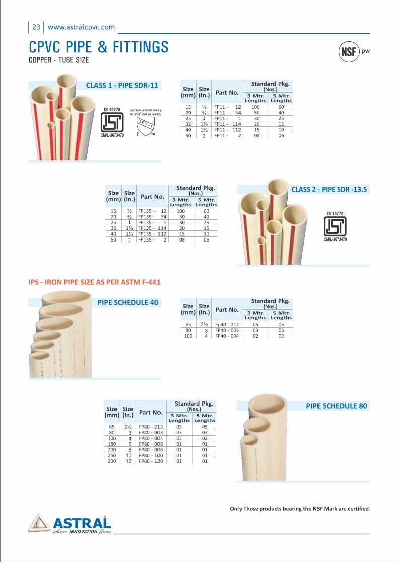
IPS ‐ IRON PIPE SIZE AS PER ASTM F‐441
PIPE SCHEDULE 40Size
(mm)Size(In.) Part No.
Standard Pkg.(Nos.)
3 Mtr.Lengths
5 Mtr.Lengths
6580
100
2½34
Fp40 ‐ 212FP40 ‐ 003FP40 ‐ 004
050302
050302
23 www.astralcpvc.com
CPVC PIPE & FITTINGS pw
Only Those products bearing the NSF Mark are certified.
CLASS 2 ‐ PIPE SDR ‐13.5
CM/L-3673470
IS 15778
Size(mm)
Size(In.) Part No.
Standard Pkg.(Nos.)
3 Mtr.Lengths
5 Mtr.Lengths
152025324050
½¾1
1¼1½2
FP135 ‐FP135 ‐FP135 ‐FP135 ‐FP135 ‐FP135 ‐
1234
1114112
2
1005030201508
604025151006
PIPE SCHEDULE 80Size(mm)
Size(In.) Part No.
Standard Pkg.(Nos.)
3 Mtr.Lengths
5 Mtr.Lengths
6580
100150200250300
2½3468
1012
FP80 ‐ 212FP80 ‐ 003FP80 ‐ 004FP80 ‐ 006FP80 ‐ 008FP80 ‐ 100FP80 ‐ 120
05030201010101
05030201010101
Size(mm)
Size(In.) Part No.
Standard Pkg.(Nos.)
3 Mtr.Lengths
5 Mtr.Lengths
152025324050
½¾1
1¼1½2
FP11 ‐FP11 ‐FP11 ‐FP11 ‐FP11 ‐FP11 ‐
1234
1114112
2
1005030201508
604025151006
COPPER - TUBE SIZE
CLASS 1 ‐ PIPE SDR‐11
CM/L-3673470
IS 15778
FlowGuard™ is the registered mark of The Lubrizol Corporation.The Lubrizol Corporation is a Berkshire Hathaway company.
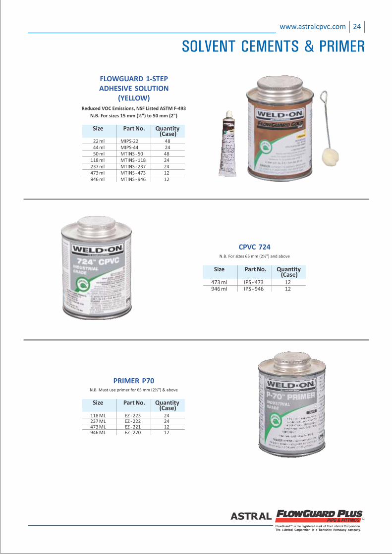
CPVC 724N.B. For sizes 65 mm (2½") and above
Size Part No. Quantity (Case) 473 ml IPS ‐ 473 12 946 ml IPS ‐ 946 12
N.B. Must use primer for 65 mm (2½") & above
PRIMER P70
Size Part No. Quantity (Case) 118 ML EZ ‐ 223 24 237 ML EZ ‐ 222 24 473 ML EZ ‐ 221 12 946 ML EZ ‐ 220 12
FLOWGUARD 1‐STEPADHESIVE SOLUTION
(YELLOW) Reduced VOC Emissions, NSF Listed ASTM F‐493
N.B. For sizes 15 mm (½") to 50 mm (2")
Size Part No. Quantity (Case)
22 ml MIPS‐22 48 44 ml MIPS‐44 24 50 ml MTINS ‐ 50 48 118 ml MTINS ‐ 118 24 237 ml MTINS ‐ 237 24 473 ml MTINS ‐ 473 12 946 ml MTINS ‐ 946 12
24www.astralcpvc.com
SOLVENT CEMENTS & PRIMER
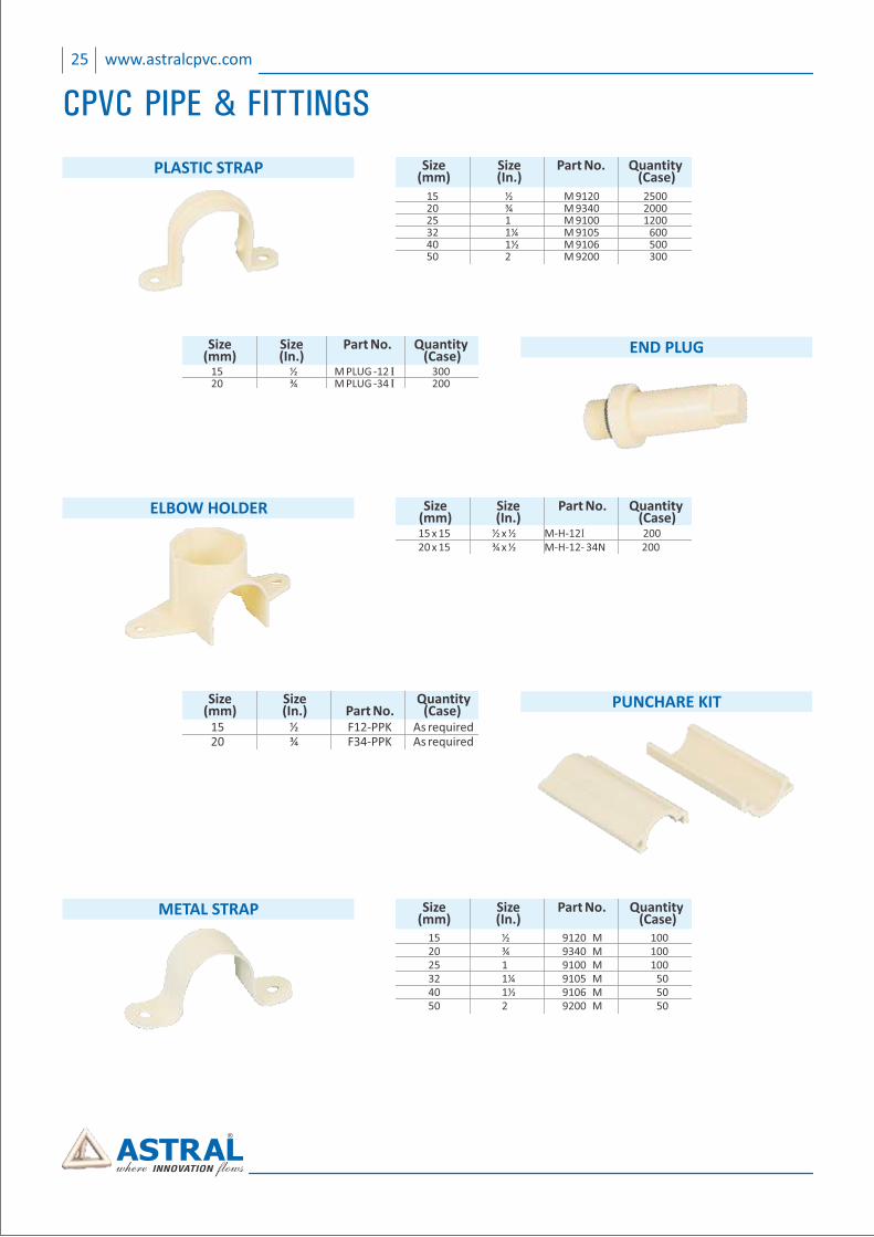
PLASTIC STRAP
15 ½ M 9120 2500 20 ¾ M 9340 2000 25 1 M 9100 1200 32 1¼ M 9105 600 40 1½ M 9106 500 50 2 M 9200 300
Size Size QuantityPart No. (mm) (In.) (Case)
ELBOW HOLDER
15 x 15 ½ x ½ M‐H‐12I 200 20 x 15 ¾ x ½ M‐ 2‐ 34 200H‐1 N
Size Size QuantityPart No. (mm) (In.) (Case)
END PLUG Size Size QuantityPart No. (mm) (In.) (Case)
15 ½ M PLUG ‐12 I 300 20 ¾ M PLUG ‐34 I 200
PUNCHARE KIT Size Size Quantity (mm) (In.) Part No. (Case) 15 ½ F12‐PPK As required 20 ¾ F34‐PPK As required
25 www.astralcpvc.com
CPVC PIPE & FITTINGS
METAL STRAP
15 ½ 9120 M 100 20 ¾ 9340 M 100 25 1 9100 M 100 32 1¼ 9105 M 50 40 1½ 9106 M 50 50 2 9200 M 50
Size Size QuantityPart No. (mm) (In.) (Case)
FlowGuard™ is the registered mark of The Lubrizol Corporation.The Lubrizol Corporation is a Berkshire Hathaway company.
26www.astralcpvc.com
CPVC PIPE & FITTINGS
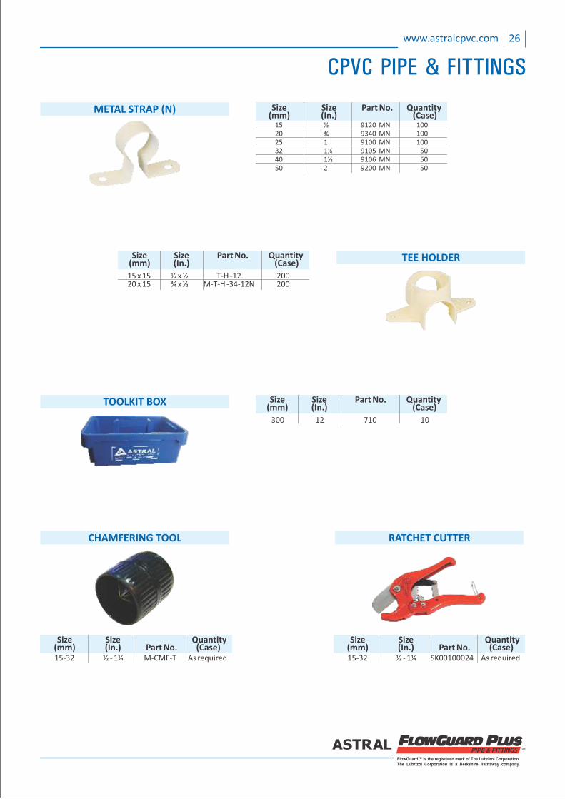
METAL STRAP (N)
15 ½ 9120 MN 100 20 ¾ 9340 MN 100 25 1 9100 MN 100 32 1¼ 9105 MN 50 40 1½ 9106 MN 50 50 2 9200 MN 50
Size Size QuantityPart No. (mm) (In.) (Case)
15 x 15 ½ x ½ T‐H ‐12 200 20 x 15 ¾ x ½ M‐T‐H ‐34‐12N 200
Size Size QuantityPart No. (mm) (In.) (Case)
TEE HOLDER
CHAMFERING TOOL
Size Size Quantity (mm) (In.) Part No. (Case) 15‐32 ½ ‐ 1¼ M‐CMF‐T As required
300 12 710 10
Size Size QuantityPart No. (mm) (In.) (Case)
TOOLKIT BOX
RATCHET CUTTER
Size Size Quantity (mm) (In.) Part No. (Case) 15‐32 ½ ‐ 1¼ SK00100024 As required
27 www.astralcpvc.com
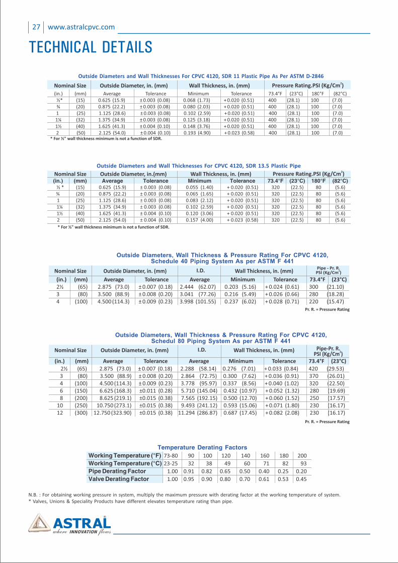
TECHNICAL DETAILS
N.B. : For obtaining working pressure in system, multiply the maximum pressure with derating factor at the working temperature of system. * Valves, Unions & Speciality Products have different elevates temperature rating than pipe.
Outside Diameters and Wall Thicknesses For CPVC 4120, SDR 11 Plastic Pipe As Per ASTM D‐2846Outside Diameters and Wall Thicknesses For CPVC 4120, SDR 11 Plastic Pipe As Per ASTM D‐2846Outside Diameters and Wall Thicknesses For CPVC 4120, SDR 11 Plastic Pipe As Per ASTM D‐2846
Wall Thickness, in. (mm)Outside Diameter, in. (mm)Nominal Size
(in.) (mm) Average Tolerance Minimum Tolerance 73.4°F (23°C) 180°F (82°C) ½* (15) 0.625 (15.9) ± 0.003 (0.08) 0.068 (1.73) + 0.020 (0.51) 400 (28.1) 100 (7.0) ¾ (20) 0.875 (22.2) ± 0.003 (0.08) 0.080 (2.03) + 0.020 (0.51) 400 (28.1) 100 (7.0) 1 (25) 1.125 (28.6) ± 0.003 (0.08) 0.102 (2.59) + 0.020 (0.51) 400 (28.1) 100 (7.0) 1¼ (32) 1.375 (34.9) ± 0.003 (0.08) 0.125 (3.18) + 0.020 (0.51) 400 (28.1) 100 (7.0) 1½ (40) 1.625 (41.3) ± 0.004 (0.10) 0.148 (3.76) + 0.020 (0.51) 400 (28.1) 100 (7.0) 2 (50) 2.125 (54.0) ± 0.004 (0.10) 0.193 (4.90) + 0.023 (0.58) 400 (28.1) 100 (7.0)
2Pressure Rating.PSI (Kg/Cm )
* For ½" wall thickness minimum is not a function of SDR.
Wall Thickness, in. (mm)Outside Diameter, in.(mm)Nominal Size (in.) (mm) Average Tolerance Minimum Tolerance 73.4°F (23°C) 180°F (82°C) ½ * (15) 0.625 (15.9) ± 0.003 (0.08) 0.055 (1.40) + 0.020 (0.51) 320 (22.5) 80 (5.6) ¾ (20) 0.875 (22.2) ± 0.003 (0.08) 0.065 (1.65) + 0.020 (0.51) 320 (22.5) 80 (5.6) 1 (25) 1.125 (28.6) ± 0.003 (0.08) 0.083 (2.12) + 0.020 (0.51) 320 (22.5) 80 (5.6) 1¼ (32) 1.375 (34.9) ± 0.003 (0.08) 0.102 (2.59) + 0.020 (0.51) 320 (22.5) 80 (5.6) 1½ (40) 1.625 (41.3) ± 0.004 (0.10) 0.120 (3.06) + 0.020 (0.51) 320 (22.5) 80 (5.6) 2 (50) 2.125 (54.0) ± 0.004 (0.10) 0.157 (4.00) + 0.023 (0.58) 320 (22.5) 80 (5.6)
2Pressure Rating.PSI (Kg/Cm )
* For ½" wall thickness minimum is not a function of SDR.
Outside Diameters and Wall Thicknesses For CPVC 4120, SDR 13.5 Plastic Pipe
Temperature Derating Factors
Working Temperature (°F) 73‐80 90 100 120 140 160 180 200
Working Temperature (°C) 23‐25 32 38 49 60 71 82 93
Pipe Derating Factor 1.00 0.91 0.82 0.65 0.50 0.40 0.25 0.20
Valve Derating Factor 1.00 0.95 0.90 0.80 0.70 0.61 0.53 0.45
Wall Thickness, in. (mm)Outside Diameter, in. (mm)Nominal Size
(in.) (mm) Average Tolerance Average Minimum Tolerance 73.4°F (23°C) 73.4°F (23°C) 2½ (65) 2.875 (73.0) ± 0.007 (0.18) 2.444 (62.07) 0.203 (5.16) + 0.024 (0.61) 300 (21.10) 180 (12.65) 3 (80) 3.500 (88.9) ± 0.008 (0.20) 3.041 (77.26) 0.216 (5.49) + 0.026 (0.66) 280 (18.28) 156 (10.96) 4 (100) 4.500 (114.3) ± 0.009 (0.23) 3.998 (101.55) 0.237 (6.02) + 0.028 (0.71) 220 (15.47) 132 (09.28)
Pipe ‐ Pr. R.2PSI (Kg/Cm )
Outside Diameters, Wall Thickness & Pressure Rating For CPVC 4120,Schedule 40 Piping System As per ASTM F 441
I.D.
Pr. R. = Pressure Rating
Wall Thickness, in. (mm)Outside Diameter, in. (mm)Nominal Size
2½ (65) 2.875 (73.0) ± 0.007 (0.18) 2.288 (58.14) 0.276 (7.01) + 0.033 (0.84) 420 (29.53) 252 (17.71) 3 (80) 3.500 (88.9) ± 0.008 (0.20) 2.864 (72.75) 0.300 (7.62) + 0.036 (0.91) 370 (26.01) 222 (15.60) 4 (100) 4.500 (114.3) ± 0.009 (0.23) 3.778 (95.97) 0.337 (8.56) + 0.040 (1.02) 320 (22.50) 192 (13.49) 6 (150) 6.625 (168.3) ±0.011 (0.28) 5.710 (145.04) 0.432 (10.97) + 0.052 (1.32) 280 (19.69) 168 (11.81) 8 (200) 8.625 (219.1) ±0.015 (0.38) 7.565 (192.15) 0.500 (12.70) + 0.060 (1.52) 250 (17.57) 150 (10.54) 10 (250) 10.750 (273.1) ±0.015 (0.38) 9.493 (241.12) 0.593 (15.06) + 0.071 (1.80) 230 (16.17) 138 (09.70) 12 (300) 12.750 (323.90) ±0.015 (0.38) 11.294 (286.87) 0.687 (17.45) + 0.082 (2.08) 230 (16.17) 138 (09.70)
(in.) (mm) Average Tolerance Average Minimum Tolerance 73.4°F (23°C) 73.4°F (23°C)
Pipe‐Pr. R.2PSI (Kg/Cm )
I.D.
Outside Diameters Wall Thickness & Pressure Rating For CPVC 4120,, Schedul 80 Piping System As per ASTM F 441
Pr. R. = Pressure Rating
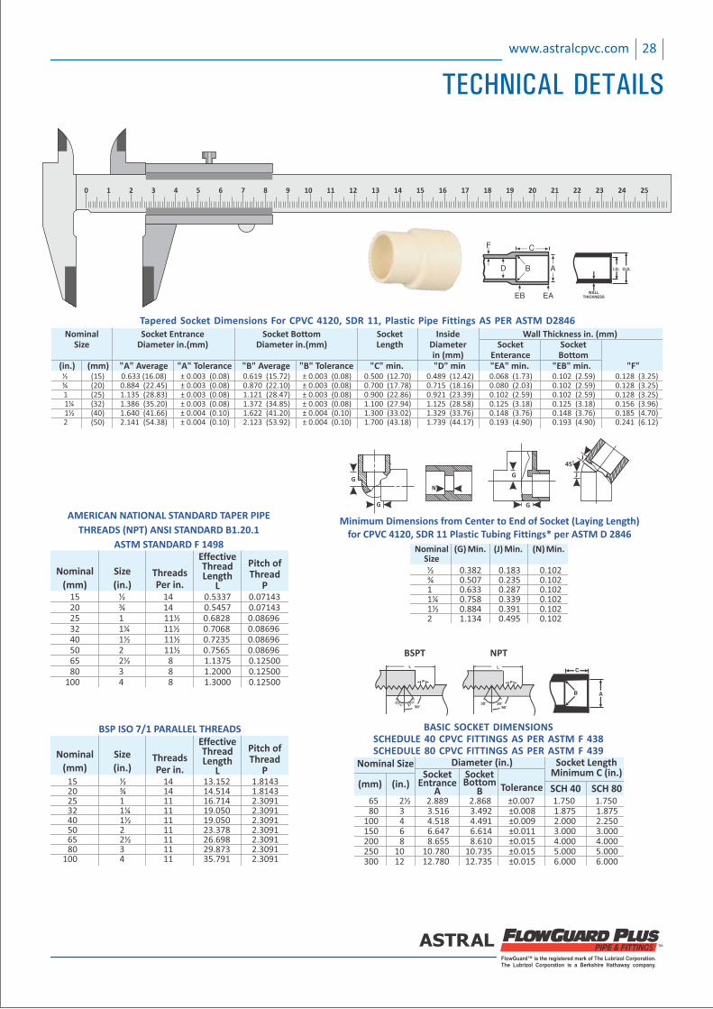
15 ½ 14 13.152 1.8143 20 ¾ 14 14.514 1.8143 25 1 11 16.714 2.3091 32 1¼ 11 19.050 2.3091 40 1½ 11 19.050 2.3091 50 2 11 23.378 2.3091 65 2½ 11 26.698 2.3091 80 3 11 29.873 2.3091 100 4 11 35.791 2.3091
ThreadsPer in.
EffectiveThreadLength
L
Pitch ofThread
P
Size
(in.)
Nominal
(mm)
BSP ISO 7/1 PARALLEL THREADS BASIC SOCKET DIMENSIONSSCHEDULE 40 CPVC FITTINGS AS PER ASTM F 438SCHEDULE 80 CPVC FITTINGS AS PER ASTM F 439
65 2½ 2.889 2.868 ±0.007 1.750 1.750 80 3 3.516 3.492 ±0.008 1.875 1.875 100 4 4.518 4.491 ±0.009 2.000 2.250 150 6 6.647 6.614 ±0.011 3.000 3.000 200 8 8.655 8.610 ±0.015 4.000 4.000 250 10 10.780 10.735 ±0.015 5.000 5.000 300 12 12.780 12.735 ±0.015 6.000 6.000
Nominal Size Diameter (in.)Socket Socket
EntranceA
BottomB Tolerance SCH 40 SCH 80
Socket LengthMinimum C (in.)
(mm) (in.)
15 ½ 14 0.5337 0.07143 20 ¾ 14 0.5457 0.07143 25 1 11½ 0.6828 0.08696 32 1¼ 11½ 0.7068 0.08696 40 1½ 11½ 0.7235 0.08696 50 2 11½ 0.7565 0.08696 65 2½ 8 1.1375 0.12500 80 3 8 1.2000 0.12500 100 4 8 1.3000 0.12500
ThreadsPer in.
EffectiveThreadLength
L
Pitch ofThread
P
Size
(in.)
Nominal
(mm)
AMERICAN NATIONAL STANDARD TAPER PIPE
THREADS (NPT) ANSI STANDARD B1.20.1
ASTM STANDARD F 1498 Nominal (G) Min. (J) Min. (N) Min. Size ½ 0.382 0.183 0.102 ¾ 0.507 0.235 0.102 1 0.633 0.287 0.102 1¼ 0.758 0.339 0.102 1½ 0.884 0.391 0.102 2 1.134 0.495 0.102
Minimum Dimensions from Center to End of Socket (Laying Length)for CPVC 4120, SDR 11 Plastic Tubing Fittings* per ASTM D 2846
G
G
G
G
N
J
J
045
BSPT NPT
Tapered Socket Dimensions For CPVC 4120, SDR 11, Plastic Pipe Fittings AS PER ASTM D2846
½ (15) 0.633 (16.08) ± 0.003 (0.08) 0.619 (15.72) ± 0.003 (0.08) 0.500 (12.70) 0.489 (12.42) 0.068 (1.73) 0.102 (2.59) 0.128 (3.25) ¾ (20) 0.884 (22.45) ± 0.003 (0.08) 0.870 (22.10) ± 0.003 (0.08) 0.700 (17.78) 0.715 (18.16) 0.080 (2.03) 0.102 (2.59) 0.128 (3.25) 1 (25) 1.135 (28.83) ± 0.003 (0.08) 1.121 (28.47) ± 0.003 (0.08) 0.900 (22.86) 0.921 (23.39) 0.102 (2.59) 0.102 (2.59) 0.128 (3.25) 1¼ (32) 1.386 (35.20) ± 0.003 (0.08) 1.372 (34.85) ± 0.003 (0.08) 1.100 (27.94) 1.125 (28.58) 0.125 (3.18) 0.125 (3.18) 0.156 (3.96) 1½ (40) 1.640 (41.66) ± 0.004 (0.10) 1.622 (41.20) ± 0.004 (0.10) 1.300 (33.02) 1.329 (33.76) 0.148 (3.76) 0.148 (3.76) 0.185 (4.70) 2 (50) 2.141 (54.38) ± 0.004 (0.10) 2.123 (53.92) ± 0.004 (0.10) 1.700 (43.18) 1.739 (44.17) 0.193 (4.90) 0.193 (4.90) 0.241 (6.12)
Nominal Socket Entrance Socket Bottom Socket Inside Wall Thickness in. (mm) Size Diameter in.(mm) Diameter in.(mm) Length Diameter Socket Socket in (mm) Enterance Bottom (in.) (mm) "A" Average "A" Tolerance "B" Average "B" Tolerance "C" min. "D" min "EA" min. "EB" min. "F"
FlowGuard™ is the registered mark of The Lubrizol Corporation.The Lubrizol Corporation is a Berkshire Hathaway company.
28www.astralcpvc.com
TECHNICAL DETAILS
FlowGuard™ is the registered mark of The Lubrizol Corporation.The Lubrizol Corporation is a Berkshire Hathaway company.
Fric
tio
n L
oss
an
d F
low
ve
loci
ty f
or
SDR
11
CTC
CP
VC
Th
erm
op
last
ic P
ipe
(Fri
ctio
n h
ead
an
d F
rict
ion
Lo
ss a
re p
er
10
0 f
eet
of
pip
e)
NO
TIC
E :
Flo
w v
elo
city
sh
ou
ld n
ot
exce
ed
5 f
eet
pe
r se
con
d. V
elo
citi
es
in e
xce
ss o
f 5
fe
et p
er
seco
nd
may
re
sult
in s
yste
m f
ailu
re a
nd
pro
pe
rty
dam
age
.
Gallons Per Minut
0
.68
1
.35
2
.03
2
.70
3
.38
4
.05
4
.73
5
.40
6
.08
6
.75
7
.43
8
.10
9
.46
1
0.6
1
1
2.1
6
1
3.5
1
1
6.8
9
VelocityFeet Per Second
VelocityFeet Per Second
VelocityFeet Per Second
VelocityFeet Per Second
VelocityFeet Per Second
VelocityFeet Per Second
Head LossFeet of Water
Per 100 Ft.
Head LossFeet of Water
Per 100 Ft.
Head LossFeet of Water
Per 100 Ft.
Head LossFeet of Water
Per 100 Ft.
Head LossFeet of Water
Per 100 Ft.
Head LossFeet of Water
Per 100 Ft.
Pressure LossPSI
Per 100 Ft.
Pressure LossPSI
Per 100 Ft.
Pressure LossPSI
Per 100 Ft.
Pressure LossPSI
Per 100 Ft.
Pressure LossPSI
Per 100 Ft.
Pressure LossPSI
Per 100 Ft.
1
2
3
4
5
6
7
8
9
10
15
20
25
30
35
40
45
50
55
60
70
80
90
100
125
1.7
1
3.4
2
5.1
6
6.8
3
8.5
4
10.2
5
11.9
6
13.6
7
15.3
8
17.0
8
3.1
9
11.5
3
24.4
3
41.6
2
62.9
1
88.1
8
117.3
2
150.2
3
186.8
5
227.1
1
1.3
8
5.0
0
10.5
9
18.0
4
27.2
7
38.2
3
50.8
6
65.1
3
81.0
0
98.4
5
0.8
0
1.6
0
2.4
0
3.2
0
4.0
0
4.7
9
5.5
9
6.3
9
7.1
9
7.9
9
11.9
9
15.9
8
0.5
0
1.8
2
3.8
5
6.5
5
9.9
1
13.8
9
18.4
7
23.6
6
29.4
2
35.7
6
75.7
8
129.1
1
0.2
2
0.7
9
1.6
7
2.8
4
4.2
9
6.0
2
8.0
1
10.2
6
12.7
6
15.5
0
32.8
5
55.9
7
0.4
8
0.9
6
1.4
4
1.9
3
2.4
1
2.8
9
3.3
7
3.8
5
4.3
3
4.8
2
7.2
2
9.6
3
12.0
4
14.4
5
16.8
6
0.1
5
0.5
3
1.1
2
1.9
1
2.8
9
4.0
5
5.3
9
6.9
0
8.5
9
10.4
3
22.1
1
37.6
7
56.9
4
79.8
2
106.1
9
0.0
6
0.2
3
0.4
9
0.8
3
1.2
5
1.7
6
2.3
4
2.9
9
3.7
2
4.5
2
9.5
8
16.3
3
24.6
9
34.6
0
46.0
3
1.6
1
3.2
3
4.8
4
6.4
6
8.0
7
9.6
8
11.3
0
12.9
1
14.5
2
16.1
4
17.7
5
1.0
9
3.9
4
8.3
5
14.2
3
21.5
1
30.1
5
40.1
1
51.3
7
63.8
9
77.6
6
92.6
5
0.4
7
1.7
1
3.6
2
6.1
7
9.3
3
13.0
7
17.3
9
22.2
7
27.7
0
33.6
6
40.1
6
0
.49
1
.75
3
.71
6
.33
9
.56
1
3.4
0
1
7.8
3
2
2.8
3
2
8.4
0
3
4.5
2
4
1.1
8
4
8.3
8
6
4.3
7
1
.16
2
.31
3
.47
4
.63
5
.78
6
.94
8
.09
9
.25
1
0.4
1
11
.56
1
2.7
2
1
3.8
8
1
6.1
9
0
.21
0
.76
1
.61
2
.74
4
.15
5
.81
7
.73
9
.90
1
2.3
1
1
4.9
6
1
7.8
5
2
0.9
7
2
7.9
0
0.1
3
0.4
9
1.0
3
1.7
6
2.6
6
3.7
3
4.9
6
6.3
5
7.8
9
9.6
0
11
.45
13
.45
17
.89
22
.91
28
.50
34
.64
52
.37
0.0
6
0.2
1
0.4
5
0.7
6
1.1
5
1.6
2
2.1
5
2.7
5
3.4
2
4.1
6
4.9
6
5.8
3
7.7
6
9.9
3
12
.35
15
.02
22
.70
1 /in
.2
3 /in
.4
1 in
.1
/in
.1
41
/in
.1
22
in.
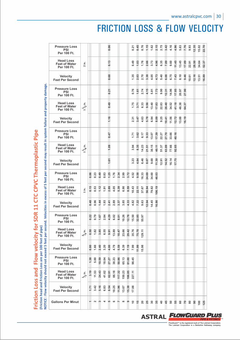
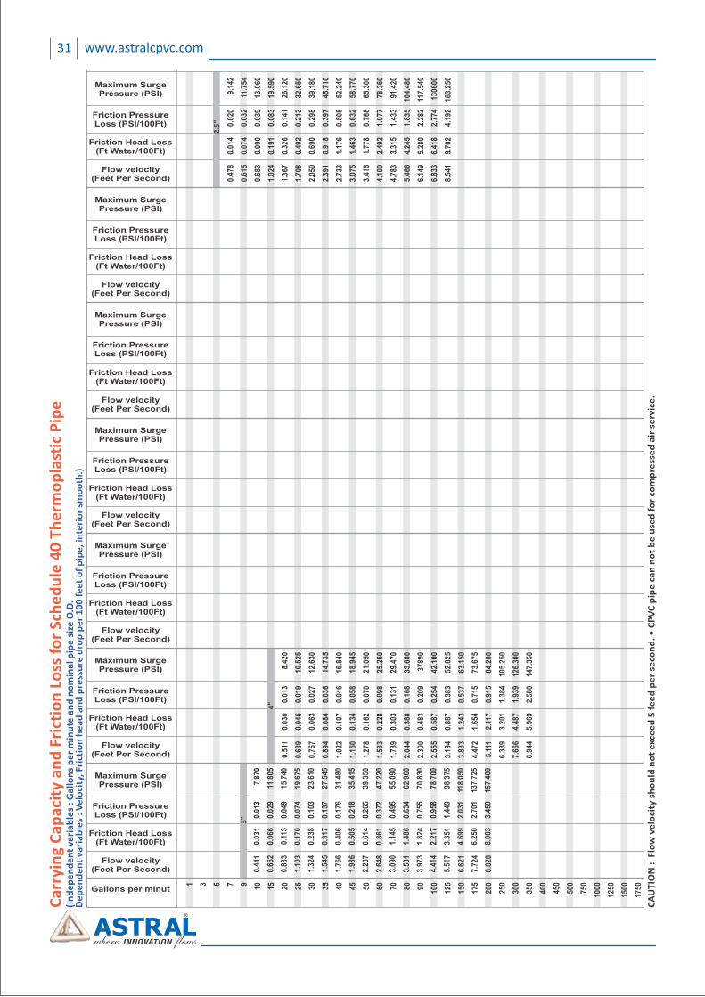
30www.astralcpvc.com
FRICTION LOSS & FLOW VELOCITY
FRICTION LOSS IN FITTINGS
Friction losses through fittings are calculated from
the equivalent length of straigth pipe which would produce
the same friction loss in the fluid. The equivalent lengths of
pipe for common fittings are given here.
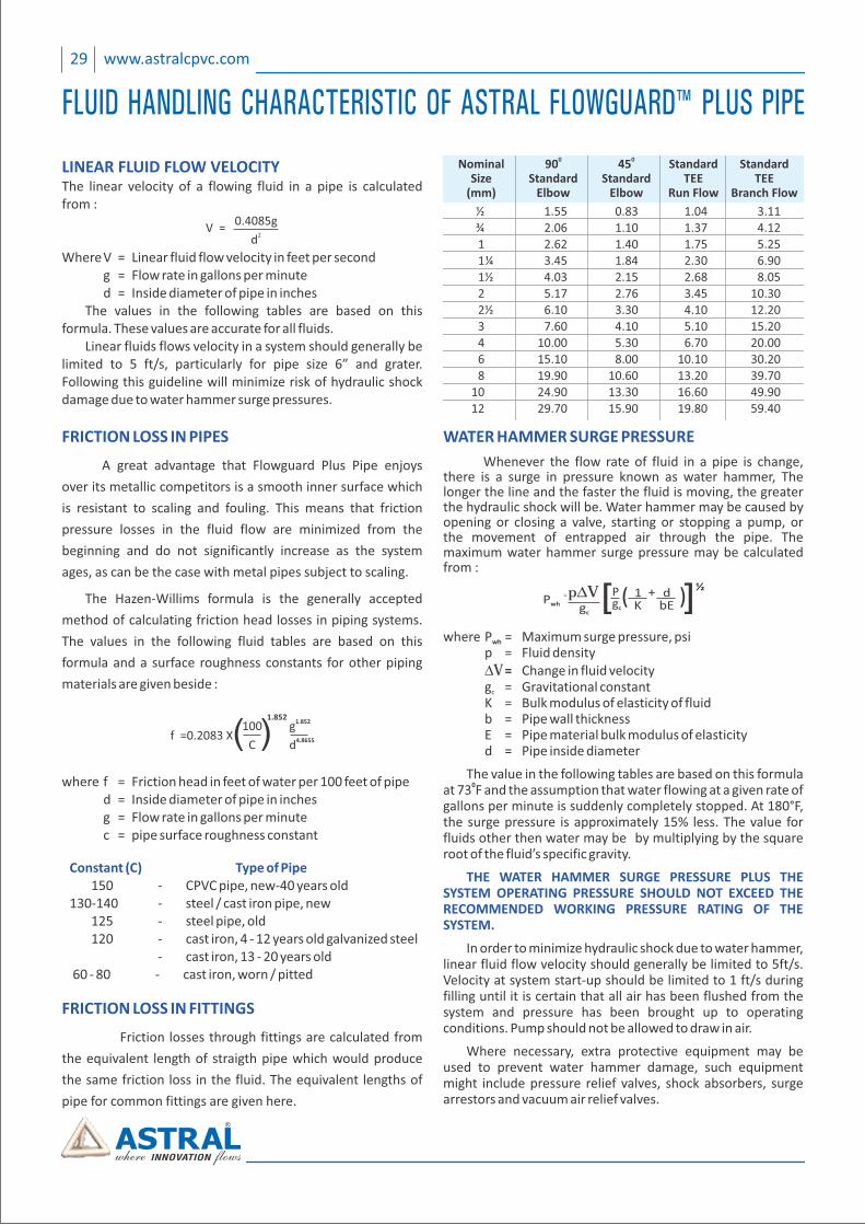
LINEAR FLUID FLOW VELOCITYThe linear velocity of a flowing fluid in a pipe is calculated from :
Where V = Linear fluid flow velocity in feet per second g = low rate in gallons per minuteF d = nside diameter of pipe in inchesI The values in the following tables are based on this formula. These values are accurate for all fluids. Linear fluids flows velocity in a system should generally be limited to 5 ft/s, particularly for pipe size 6” and grater. Following this guideline will minimize risk of hydraulic shock damage due to water hammer surge pressures.
V =0.4085g
2d
f =0.2083 X100
C( )1.852
1.852g4.8655d
FRICTION LOSS IN PIPES
A great advantage that Flowguard Plus Pipe enjoys
over its metallic competitors is a smooth inner surface which
is resistant to scaling and fouling. This means that friction
pressure losses in the fluid flow are minimized from the
beginning and do not significantly increase as the system
ages, as can be the case with metal pipes subject to scaling.
The Hazen‐Willims formula is the generally accepted
method of calculating friction head losses in piping systems.
The values in the following fluid tables are based on this
formula and a surface roughness constants for other piping
materials are given beside :
where f = Friction head in feet of water per 100 feet of pipe d = Inside diameter of pipe in inches g = Flow rate in gallons per minute c = pipe surface roughness constant
Constant (C) Type of Pipe 150 ‐ CPVC pipe, new‐40 years old 130‐140 ‐ steel / cast iron pipe, new 125 ‐ steel pipe, old 120 ‐ cast iron, 4 ‐ 12 years old galvanized steel ‐ cast iron, 13 ‐ 20 years old 60 ‐ 80 ‐ cast iron, worn / pitted
½ 1.55 0.83 1.04 3.11
¾ 2.06 1.10 1.37 4.12
1 2.62 1.40 1.75 5.25
1 ¼ 3.45 1.84 2.30 6.90
1 ½ 4.03 2.15 2.68 8.05
2 5.17 2.76 3.45 10.30
2 ½ 6.10 3.30 4.10 12.20
3 7.60 4.10 5.10 15.20
4 10.00 5.30 6.70 20.00
6 15.10 8.00 10.10 30.20
8 19.90 10.60 13.20 39.70
10 24.90 13.30 16.60 49.90
12 29.70 15.90 19.80 59.40
0 0 Nominal 90 45 Standard Standard Size Standard Standard TEE TEE (mm) Elbow Elbow Run Flow Branch Flow
WATER HAMMER SURGE PRESSURE
Whenever the flow rate of fluid in a pipe is change, there is a surge in pressure known as water hammer, The longer the line and the faster the fluid is moving, the greater the hydraulic shock will be. Water hammer may be caused by opening or closing a valve, starting or stopping a pump, or the movement of entrapped air through the pipe. The maximum water hammer surge pressure may be calculated from :
where P = Maximum surge pressure, psiwh
p = Fluid density DV = Change in fluid velocity� � g = Gravitational constantc
� K = Bulk modulus of elasticity of fluid = ipe wall thicknessb P E = Pipe material bulk modulus of elasticity d = Pipe inside diameter
The value in the following tables are based on this formula 0at 73 F and the assumption that water flowing at a given rate of
gallons per minute is suddenly completely stopped. At 180°F, the surge pressure is approximately 15% less. The value for fluids other then water may be by multiplying by the square root of the fluid’s specific gravity.
THE WATER HAMMER SURGE PRESSURE PLUS THE SYSTEM OPERATING PRESSURE SHOULD NOT EXCEED THE RECOMMENDED WORKING PRESSURE RATING OF THE SYSTEM.
In order to minimize hydraulic shock due to water hammer, linear fluid flow velocity should generally be limited to 5ft/s. Velocity at system start‐up should be limited to 1 ft/s during filling until it is certain that all air has been flushed from the system and pressure has been brought up to operating conditions. Pump should not be allowed to draw in air.
Where necessary, extra protective equipment may be used to prevent water hammer damage, such equipment might include pressure relief valves, shock absorbers, surge arrestors and vacuum air relief valves.
=P wh
pDVgc
[ ] ½1K
dbE
+gc
P
29 www.astralcpvc.com
FLUID HANDLING CHARACTERISTIC OF ASTRAL FLOWGUARD™ PLUS PIPE
31 www.astralcpvc.com
3"
2.5
"
4"
Ca
rryi
ng
Ca
pa
city
an
d F
rict
ion
Lo
ss f
or
Sch
ed
ule
40
Th
erm
op
last
ic P
ipe
(In
de
pe
nd
en
t va
ria
ble
s :
Ga
llo
ns
pe
r m
inu
te a
nd
no
min
al p
ipe
siz
e O
.D.
De
pe
nd
en
t va
ria
ble
s :
Ve
loci
ty, F
rict
ion
he
ad
an
d p
ress
ure
dro
p p
er
10
0 f
ee
t o
f p
ipe
, in
teri
or
smo
oth
.)
CA
UT
ION
: F
low
ve
loci
ty s
ho
uld
no
t ex
cee
d 5
fe
ed
pe
r se
con
d.
• C
PV
C p
ipe
ca
n n
ot
be
use
d f
or
com
pre
sse
d a
ir s
erv
ice
.
FlowGuard™ is the registered mark of The Lubrizol Corporation.The Lubrizol Corporation is a Berkshire Hathaway company.
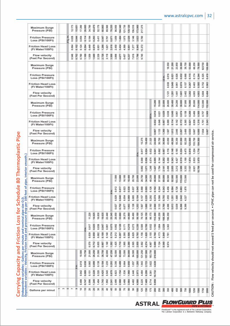
32www.astralcpvc.com
6 in
.
8 in
.
10
in.
12
in.
4 in
.
3 in
.
12
/ in
.2
Ca
rryi
ng
Ca
pa
city
an
d F
rict
ion
Lo
ss f
or
Sch
ed
ule
80
Th
erm
op
last
ic P
ipe
(In
de
pe
nd
en
t va
ria
ble
s :
Ga
llo
ns
pe
r m
inu
te a
nd
no
min
al p
ipe
siz
e O
.D.
De
pe
nd
en
t va
ria
ble
s :
Ve
loci
ty,
Fric
tio
n h
ea
d a
nd
pre
ssu
re d
rop
pe
r 1
00
fe
et
of
pip
e,
inte
rio
r sm
oo
th.)
CA
UT
ION
: F
low
ve
loci
ty s
ho
uld
no
t ex
cee
d 5
fe
ed
pe
r se
con
d.
• C
PV
C p
ipe
ca
n n
ot
be
use
d f
or
com
pre
sse
d a
ir s
erv
ice
.
33 www.astralcpvc.com
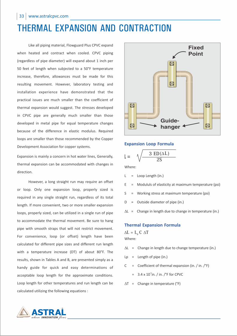
Expansion Loop Formula
Where:
L = Loop Length (in.)
E = Modululs of elasticity at maximum temperature (psi)
S = Working stress at maximum temperature (psi)
D = Outside diameter of pipe (in.)
DL = Change in length due to change in temperature (in.)
3�ED (D L�)L = 2S
Thermal Expansion Formula
DL�=�L C�DTp�
Where:
DL = Change in length due to change temperature (in.)
Lp = Length of pipe (in.)
C = Coefficient of thermal expansion (in. / in. /°F)
‐5 = 3.4 x 10 in. / in. /°F for CPVC
DT = Change in temperature (°F)
Guide-hanger
FixedPoint
Like all piping material, Flowguard Plus CPVC expand
when heated and contract when cooled. CPVC piping
(regardless of pipe diameter) will expand about 1 inch per
50 feet of length when subjected to a 50°F temperature
increase, therefore, allowances must be made for this
resulting movement. However, laboratory testing and
installation experience have demonstrated that the
practical issues are much smaller than the coefficient of
thermal expansion would suggest. The stresses developed
in CPVC pipe are generally much smaller than those
developed in metal pipe for equal temperature changes
because of the difference in elastic modulus. Required
loops are smaller than those recommended by the Copper
Development Association for copper systems.
Expansion is mainly a concern in hot water lines, Generally,
thermal expansion can be accommodated with changes in
direction.
However, a long straight run may require an offset
or loop. Only one expansion loop, properly sized is
required in any single straight run, regardless of its total
length. If more convenient, two or more smaller expansion
loops, properly sized, can be utilized in a single run of pipe
to accommodate the thermal movement. Be sure to hang
pipe with smooth straps that will not restrict movement.
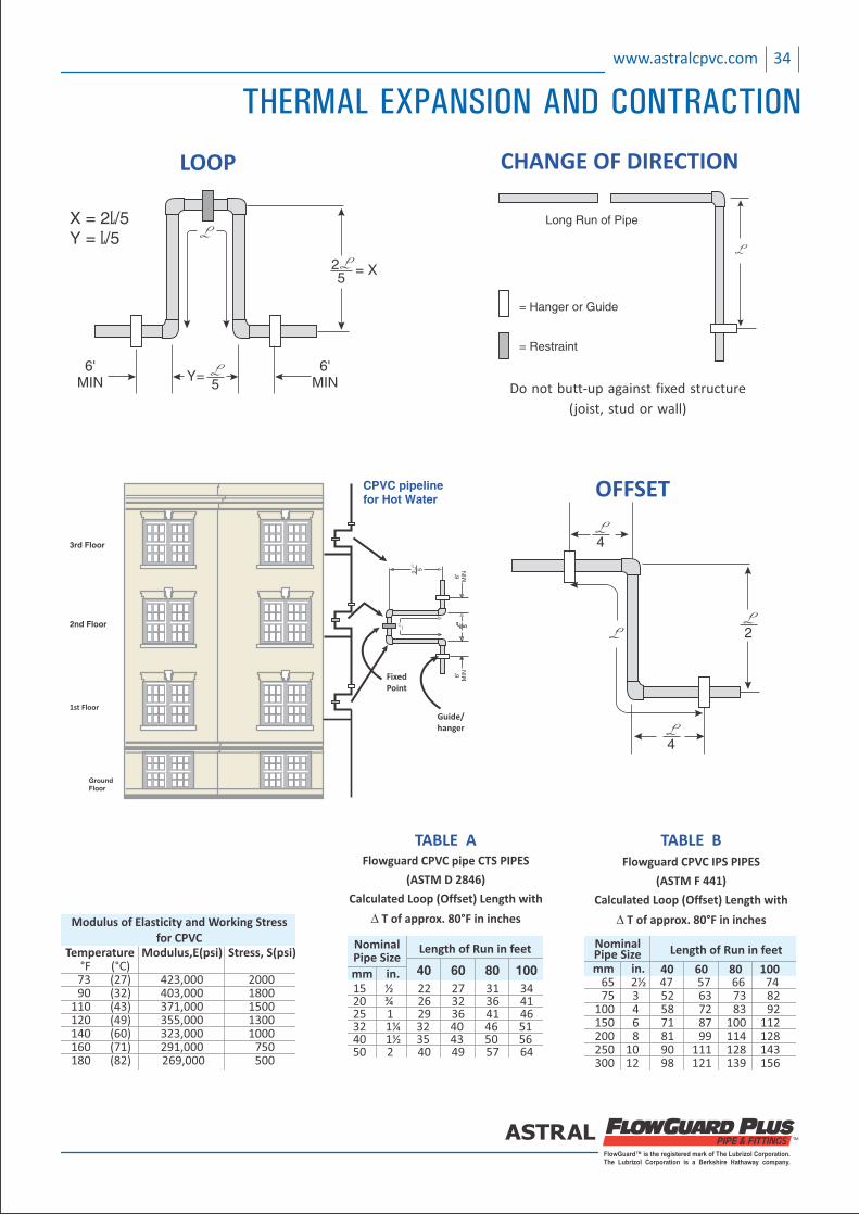
For convenience, loop (or offset) length have been
calculated for different pipe sizes and different run length
with a temperature increase (DT) of about 80°F. The
results, shown in Tables A and B, are presented simply as a
handy guide for quick and easy determinations of
acceptable loop length for the approximate conditions.
Loop length for other temperatures and run length can be
calculated utilizing the following equations :
THERMAL EXPANSION AND CONTRACTION
FlowGuard™ is the registered mark of The Lubrizol Corporation.The Lubrizol Corporation is a Berkshire Hathaway company.
4
2
4
OFFSET
25
6'MIN
6'MIN5
LOOP
= X
Y=
X = 2L/5Y = L/5
Modulus of Elasticity and Working Stressfor CPVC
Temperature Modulus,E(psi) Stress, S(psi) °F (°C) 73 (27) 423,000 2000 90 (32) 403,000 1800 110 (43) 371,000 1500 120 (49) 355,000 1300 140 (60) 323,000 1000 160 (71) 291,000 750 180 (82) 269,000 500
Long Run of Pipe
CHANGE OF DIRECTION
= Hanger or Guide
= Restraint
Do not butt‐up against fixed structure
(joist, stud or wall)
Flowguard CPVC pipe CTS PIPES
(ASTM D 2846)
Calculated Loop (Offset) Length with
D T of approx. 80°F in inches
TABLE A
15 ½ 22 27 31 34 20 ¾ 26 32 36 41 25 1 29 36 41 46 32 1¼ 32 40 46 51 40 1½ 35 43 50 56 50 2 40 49 57 64
40 60 80 100
Length of Run in feetNominalPipe Sizemm in.
3rd Floor
2nd Floor
1st Floor
GroundFloor
2 5
6'
MIN
6'
MIN
5
Loo
p
CPVC pipeline for Hot Water
FixedPoint
Guide/hanger
Flowguard CPVC IPS PIPES
(ASTM F 441)
Calculated Loop (Offset) Length with
D T of approx. 80°F in inches
TABLE B
65 2½ 47 57 66 74 75 3 52 63 73 82 100 4 58 72 83 92 150 6 71 87 100 112 200 8 81 99 114 128 250 10 90 111 128 143 300 12 98 121 139 156
NominalPipe Size
40 60 80 100
Length of Run in feet
mm in.
34www.astralcpvc.com
THERMAL EXPANSION AND CONTRACTION
35 www.astralcpvc.com
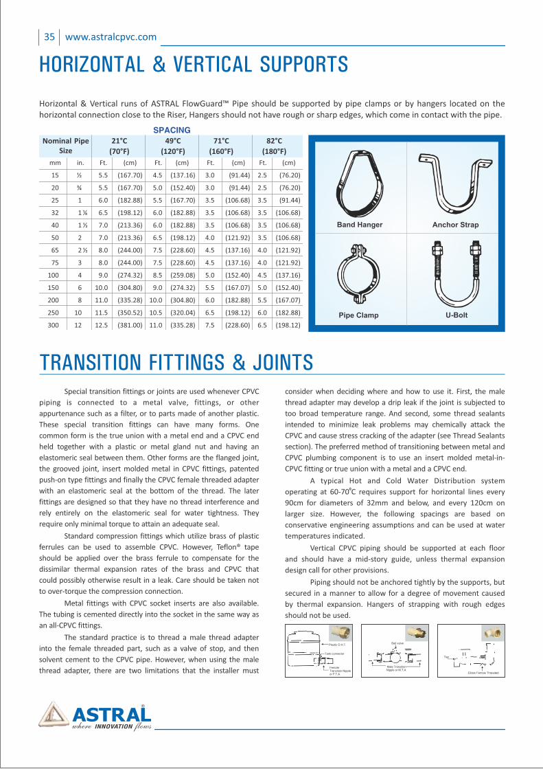
Horizontal & Vertical runs of ASTRAL FlowGuard™ Pipe should be supported by pipe clamps or by hangers located on the horizontal connection close to the iser, angers should not have rough or sharp edges, which come in contact with the pipe. R H
Anchor Strap
Pipe Clamp
Band Hanger
U-Bolt
mm in. Ft. (cm) Ft. (cm) Ft. (cm) Ft. (cm)
15 ½ 5.5 (167.70) 4.5 (137.16) 3.0 (91.44) 2.5 (76.20)
20 ¾ 5.5 (167.70) 5.0 (152.40) 3.0 (91.44) 2.5 (76.20)
25 1 6.0 (182.88) 5.5 (167.70) 3.5 (106.68) 3.5 (91.44)
32 1 ¼ 6.5 (198.12) 6.0 (182.88) 3.5 (106.68) 3.5 (106.68)
40 1 ½ 7.0 (213.36) 6.0 (182.88) 3.5 (106.68) 3.5 (106.68)
50 2 7.0 (213.36) 6.5 (198.12) 4.0 (121.92) 3.5 (106.68)
65 2 ½ 8.0 (244.00) 7.5 (228.60) 4.5 (137.16) 4.0 (121.92)
75 3 8.0 (244.00) 7.5 (228.60) 4.5 (137.16) 4.0 (121.92)
100 4 9.0 (274.32) 8.5 (259.08) 5.0 (152.40) 4.5 (137.16)
150 6 10.0 (304.80) 9.0 (274.32) 5.5 (167.07) 5.0 (152.40)
200 8 11.0 (335.28) 10.0 (304.80) 6.0 (182.88) 5.5 (167.07)
250 10 11.5 (350.52) 10.5 (320.04) 6.5 (198.12) 6.0 (182.88)
300 12 12.5 (381.00) 11.0 (335.28) 7.5 (228.60) 6.5 (198.12)
SPACING
Nominal PipeSize
21°C
(70°F)
49°C
(120°F)
71°C
(160°F)
82°C
(180°F)
Plastic O.H.T.
Tank connector
FemaleTransition Nippleor F.T.A.
Ball valve
Male TransitionNipple or M.T.A.
Elbow Female Threaded
Tap
Special transition fittings or joints are used whenever CPVC
piping is connected to a metal valve, fittings, or other
appurtenance such as a filter, or to parts made of another plastic.
These special transition fittings can have many forms. One
common form is the true union with a metal end and a CPVC end
held together with a plastic or metal gland nut and having an
elastomeric seal between them. Other forms are the flanged joint,
the grooved joint, insert molded metal in CPVC fittings, patented
push‐on type fittings and finally the CPVC female threaded adapter
with an elastomeric seal at the bottom of the thread. The later
fittings are designed so that they have no thread interference and
rely entirely on the elastomeric seal for water tightness. They
require only minimal torque to attain an adequate seal.
Standard compression fittings which utilize brass of plastic
ferrules can be used to assemble CPVC. However, Teflon® tape
should be applied over the brass ferrule to compensate for the
dissimilar thermal expansion rates of the brass and CPVC that
could possibly otherwise result in a leak. Care should be taken not
to over‐torque the compression connection.
Metal fittings with CPVC socket inserts are also available.
The tubing is cemented directly into the socket in the same way as
an all‐CPVC fittings.
The standard practice is to thread a male thread adapter
into the female threaded part, such as a valve of stop, and then
solvent cement to the CPVC pipe. However, when using the male
thread adapter, there are two limitations that the installer must
TRANSITION FITTINGS & JOINTSconsider when deciding where and how to use it. First, the male
thread adapter may develop a drip leak if the joint is subjected to
too broad temperature range. And second, some thread sealants
intended to minimize leak problems may chemically attack the
CPVC and cause stress cracking of the adapter (see Thread Sealants
section). The preferred method of transitioning between metal and
CPVC plumbing component is to use an insert molded metal‐in‐
CPVC fitting or true union with a metal and a CPVC end.
A typical Hot and Cold Water Distribution system 0operating at 60‐70 C requires support for horizontal lines every
90cm for diameters of 32mm and below, and every 120cm on
larger size. However, the following spacings are based on
conservative engineering assumptions and can be used at water
temperatures indicated.
Vertical CPVC piping should be supported at each floor
and should have a mid‐story guide, unless thermal expansion
design call for other provisions.
Piping should not be anchored tightly by the supports, but
secured in a manner to allow for a degree of movement caused
by thermal expansion. Hangers of strapping with rough edges
should not be used.
HORIZONTAL & VERTICAL SUPPORTS
FlowGuard™ is the registered mark of The Lubrizol Corporation.The Lubrizol Corporation is a Berkshire Hathaway company.
36www.astralcpvc.com
TRENCHING
The following trenching and burial procedures should be
used to protect the piping system.
1. The trench should be excavated to ensure the sides will be
stable under all working conditions.
2. The trench should be wide enough to provide adequate
room for the following :
A. Joining the pipe in the trench.
B. Snaking the pipe from side or side to compensate for
expansion and contraction.
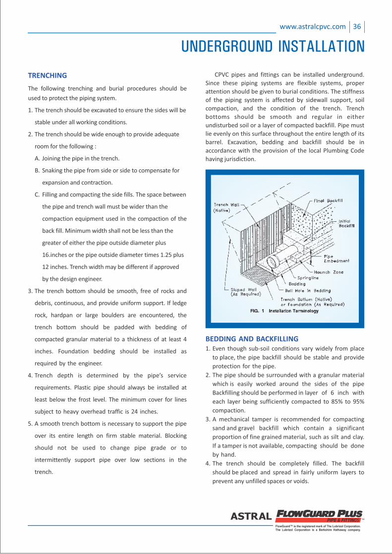
C. Filling and compacting the side fills. The space between
the pipe and trench wall must be wider than the
compaction equipment used in the compaction of the
back fill. Minimum width shall not be less than the
greater of either the pipe outside diameter plus
16.inches or the pipe outside diameter times 1.25 plus
12 inches. Trench width may be different if approved
by the design engineer.
3. The trench bottom should be smooth, free of rocks and
debris, continuous, and provide uniform support. If ledge
rock, hardpan or large boulders are encountered, the
trench bottom should be padded with bedding of
compacted granular material to a thickness of at least 4
inches. Foundation bedding should be installed as
required by the engineer.
4. Trench depth is determined by the pipe’s service
requirements. Plastic pipe should always be installed at
least below the frost level. The minimum cover for lines
subject to heavy overhead traffic is 24 inches.
5. A smooth trench bottom is necessary to support the pipe
over its entire length on firm stable material. Blocking
should not be used to change pipe grade or to
intermittently support pipe over low sections in the
trench.
CPVC pipes and fittings can be installed underground.
Since these piping systems are flexible systems, proper
attention should be given to burial conditions. The stiffness
of the piping system is affected by sidewall support, soil
compaction, and the condition of the trench. Trench
bottoms should be smooth and regular in either
undisturbed soil or a layer of compacted backfill. Pipe must
lie evenly on this surface throughout the entire length of its
barrel. Excavation, bedding and backfill should be in
accordance with the provision of the local Plumbing Code
having jurisdiction.
BEDDING AND BACKFILLING1. Even though sub‐soil conditions vary widely from place
to place, the pipe backfill should be stable and provide
protection for the pipe.
2. The pipe should be surrounded with a granular material
which is easily worked around the sides of the pipe
Backfilling should be performed in layer of 6 inch with
each layer being sufficiently compacted to 85% to 95%
compaction.
3. A mechanical tamper is recommended for compacting
sand and gravel backfill which contain a significant
proportion of fine grained material, such as silt and clay.
If a tamper is not available, compacting should be done
by hand.
4. The trench should be completely filled. The backfill
should be placed and spread in fairly uniform layers to
prevent any unfilled spaces or voids.
UNDERGROUND INSTALLATION
37 www.astralcpvc.com
HANDLING :
The pipe should be handled with reasonable care.
Because thermoplastic pipe is much lighter in weight than
metal pipe, there is sometimes a tendency to throw it
around. This should be avoided.
The pipe should never be dragged or pushed from a
truck bed. Pallets for pipe should be removed with a fork
lift. Loose pipe can be rolled down timbers as long as the
pieces do not fall on each other or on any hard or uneven
surface. In all cases, severe contact with any sharp objects
(rocks, angle irons, forks on forklifts, etc.) should be
avoided.
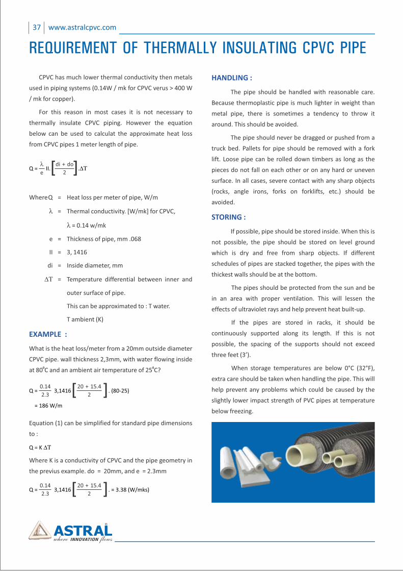
STORING :
If possible, pipe should be stored inside. When this is
not possible, the pipe should be stored on level ground
which is dry and free from sharp objects. If different
schedules of pipes are stacked together, the pipes with the
thickest walls should be at the bottom.
The pipes should be protected from the sun and be
in an area with proper ventilation. This will lessen the
effects of ultraviolet rays and help prevent heat built‐up.
If the pipes are stored in racks, it should be
continuously supported along its length. If this is not
possible, the spacing of the supports should not exceed
three feet (3’).
When storage temperatures are below 0°C (32°F),
extra care should be taken when handling the pipe. This will
help prevent any problems which could be caused by the
slightly lower impact strength of PVC pipes at temperature
below freezing.
CPVC has much lower thermal conductivity then metals
used in piping systems (0.14W / mk for CPVC verus > 400 W
/ mk for copper).
For this reason in most cases it is not necessary to
thermally insulate CPVC piping. However the equation
below can be used to calculat the approximate heat loss
from CPVC pipes 1 meter length of pipe.
Where Q = Heat loss per meter of pipe, W/m
l = Thermal conductivity. [W/mk] for CPVC,
l = 0.14 w/mk
e = Thickness of pipe, mm .068
II = 3, 1416
di = Inside diameter, mm
DT = Temperature differential between inner and
outer surface of pipe.
This can be approximated to : T water.
T ambient (K)
EXAMPLE :
What is the heat loss/meter from a 20mm outside diameter
CPVC pipe. wall thickness 2,3mm, with water flowing inside 0 0at 80 C and an ambient air temperature of 25 C?
Equation (1) can be simplified for standard pipe dimensions
to :
Where K is a conductivity of CPVC and the pipe geometry in
the previus example. do = 20mm, and e = 2.3mm
le
Q = II. .DT[ ] di + do
2
0.14
2.3Q = 3,1416 . (80‐25)
= 186 W/m
[ ] 20 + 15.4
2
Q = K DT
0.14
2.3 [ ] 20 + 15.4
2Q = 3,1416 . = 3.38 (W/mks)
REQUIREMENT OF THERMALLY INSULATING CPVC PIPE
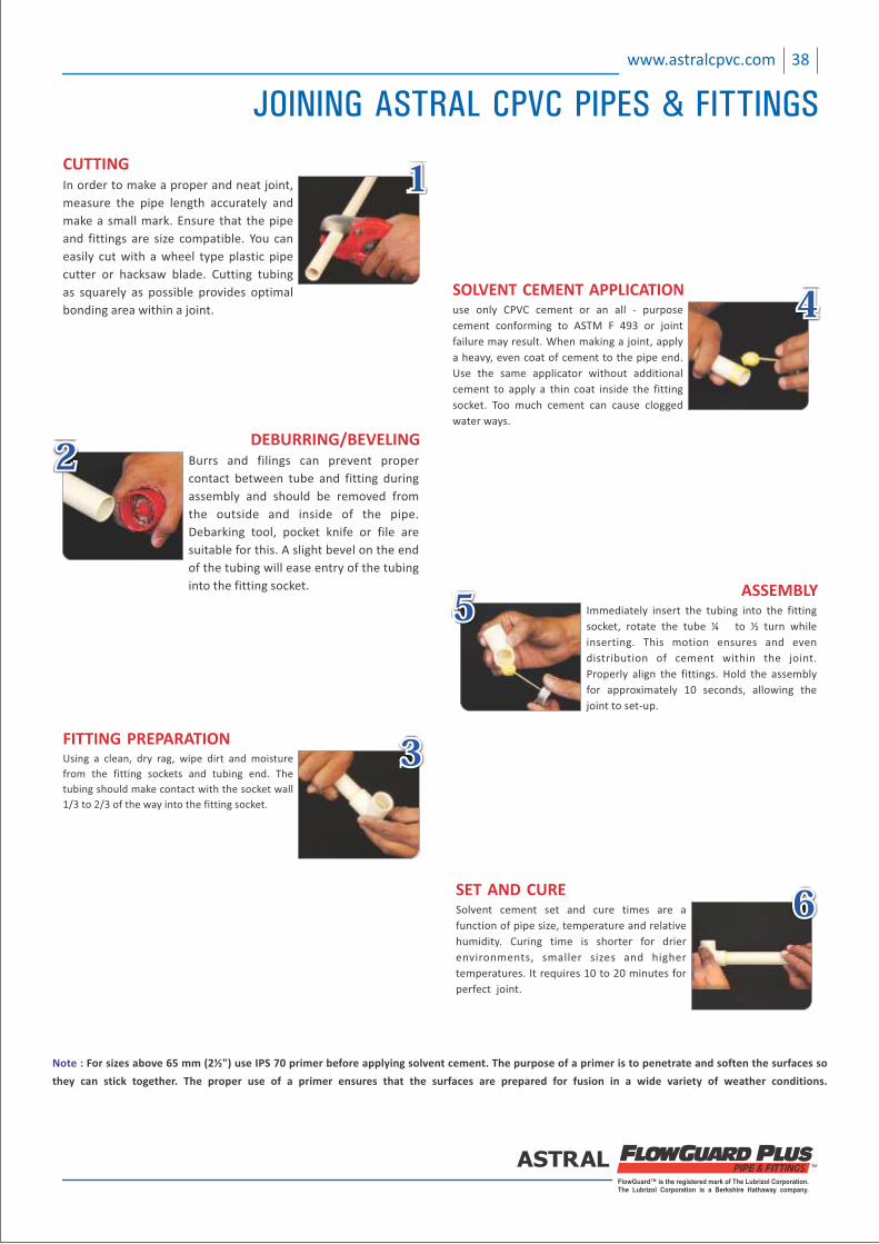
FlowGuard™ is the registered mark of The Lubrizol Corporation.The Lubrizol Corporation is a Berkshire Hathaway company.
38www.astralcpvc.com
CUTTINGIn order to make a proper and neat joint,
measure the pipe length accurately and
make a small mark. Ensure that the pipe
and fittings are size compatible. You can
easily cut with a wheel type plastic pipe
cutter or hacksaw blade. Cutting tubing
as squarely as possible provides optimal
bonding area within a joint.
111
FITTING PREPARATIONUsing a clean, dry rag, wipe dirt and moisture
from the fitting sockets and tubing end. The
tubing should make contact with the socket wall
1/3 to 2/3 of the way into the fitting socket.
333
DEBURRING/BEVELINGBurrs and filings can prevent proper
contact between tube and fitting during
assembly and should be removed from
the outside and inside of the pipe.
Debarking tool, pocket knife or file are
suitable for this. A slight bevel on the end
of the tubing will ease entry of the tubing
into the fitting socket.
222
Note : For sizes above 65 mm (2½") use IPS 70 primer before applying solvent cement. The purpose of a primer is to penetrate and soften the surfaces so
they can stick together. The proper use of a primer ensures that the surfaces are prepared for fusion in a wide variety of weather conditions.
SOLVENT CEMENT APPLICATIONuse only CPVC cement or an all ‐ purpose
cement conforming to ASTM F 493 or joint
failure may result. When making a joint, apply
a heavy, even coat of cement to the pipe end.
Use the same applicator without additional
cement to apply a thin coat inside the fitting
socket. Too much cement can cause clogged
water ways.
444
SET AND CURESolvent cement set and cure times are a
function of pipe size, temperature and relative
humidity. Curing time is shorter for drier
environments, smaller sizes and higher
temperatures. It requires 10 to 20 minutes for
perfect joint.
666
ASSEMBLYImmediately insert the tubing into the fitting
socket, rotate the tube ¼ to ½ turn while
inserting. This motion ensures and even
distribution of cement within the joint.
Properly align the fittings. Hold the assembly
for approximately 10 seconds, allowing the
joint to set‐up.
555
JOINING ASTRAL CPVC PIPES & FITTINGS
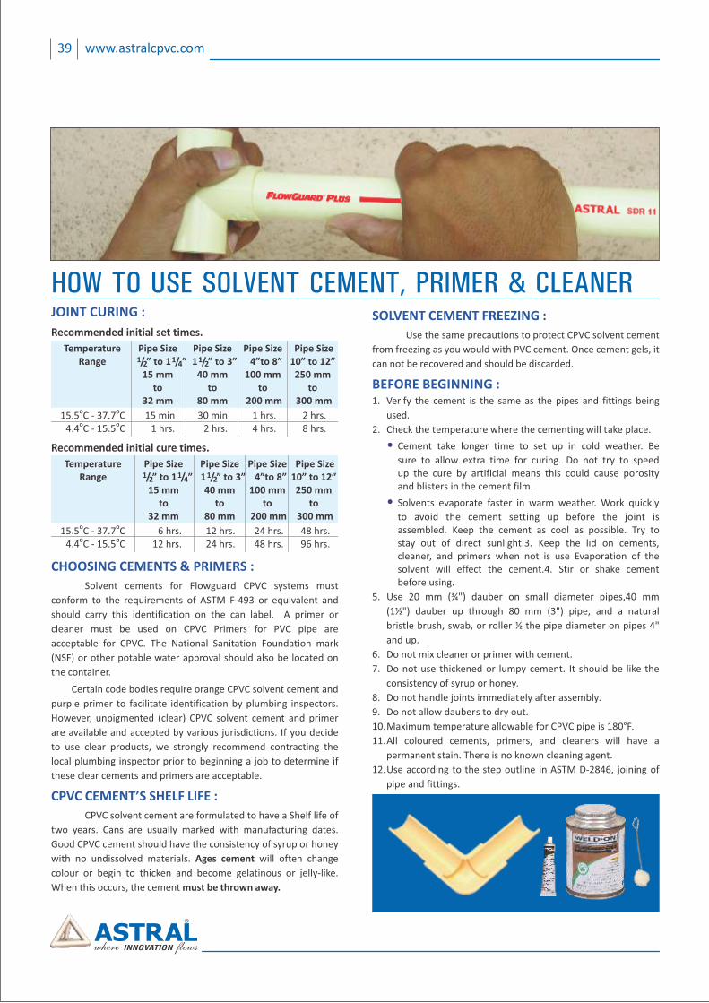
39 www.astralcpvc.com
HOW TO USE SOLVENT CEMENT, PRIMER & CLEANERJOINT CURING :
Temperature Pipe Size Pipe Size Pipe Size Pipe Size1 1 Range / 1 / ” 1 4”to 8” 10” to 12”2 4 1” to / ” to 3” 2
15 mm 40 mm 100 mm 250 mm to to to to 32 mm 80 mm 200 mm 300 mm
O O 15.5 C ‐ 37.7 C 15 min 30 min 1 hrs. 2 hrs.O O 4.4 C ‐ 15.5 C 1 hrs. 2 hrs. 4 hrs. 8 hrs.
Recommended initial set times.
Temperature Pipe Size Pipe Size Pipe Size Pipe Size1 1 Range / 1 / ” 1 4”to 8” 10” to 12”2 4 1” to / ” to 3” 2
15 mm 40 mm 100 mm 250 mm to to to to 32 mm 80 mm 200 mm 300 mm
O O 15.5 C ‐ 37.7 C 6 hrs. 12 24 hrs. 48 hrs.hrs.O O 4.4 C ‐ 15.5 C 12 hrs. 24 hrs. 48 hrs. 96 hrs.
Recommended initial cure times.
CHOOSING CEMENTS & PRIMERS :
Solvent cements for Flowguard CPVC systems must
conform to the requirements of ASTM F‐493 or equivalent and
should carry this identification on the can label. A primer or
cleaner must be used on CPVC Primers for PVC pipe are
acceptable for CPVC. The National Sanitation Foundation mark
(NSF) or other potable water approval should also be located on
the container.
Certain code bodies require orange CPVC solvent cement and
purple primer to facilitate identification by plumbing inspectors.
However, unpigmented (clear) CPVC solvent cement and primer
are available and accepted by various jurisdictions. If you decide
to use clear products, we strongly recommend contracting the
local plumbing inspector prior to beginning a job to determine if
these clear cements and primers are acceptable.
CPVC CEMENT’S SHELF LIFE :
CPVC solvent cement are formulated to have a Shelf life of
two years. Cans are usually marked with manufacturing dates.
Good CPVC cement should have the consistency of syrup or honey
with no undissolved materials. Ages cement will often change
colour or begin to thicken and become gelatinous or jelly‐like.
When this occurs, the cement must be thrown away.
SOLVENT CEMENT FREEZING :
Use the same precautions to protect CPVC solvent cement
from freezing as you would with PVC cement. Once cement gels, it
can not be recovered and should be discarded.
BEFORE BEGINNING :1. Verify the cement is the same as the pipes and fittings being
used.
2. Check the temperature where the cementing will take place.
• Cement take longer time to set up in cold weather. Be
sure to allow extra time for curing. Do not try to speed up the cure by artificial means this could cause porosity and blisters in the cement film.
• Solvents evaporate faster in warm weather. Work quickly
to avoid the cement setting up before the joint is assembled. Keep the cement as cool as possible. Try to stay out of direct sunlight.3. Keep the lid on cements, cleaner, and primers when not is use Evaporation of the solvent will effect the cement.4. Stir or shake cement before using.
5. Use 20 mm (¾") dauber on small diameter pipes,40 mm
(1½") dauber up through 80 mm (3") pipe, and a natural
bristle brush, swab, or roller ½ the pipe diameter on pipes 4"
and up.
6. Do not mix cleaner or primer with cement.
7. Do not use thickened or lumpy cement. It should be like the
consistency of syrup or honey.
8. Do not handle joints immediately after assembly.
9. Do not allow daubers to dry out.
10. Maximum temperature allowable for CPVC pipe is 180°F.
11. All coloured cements, primers, and cleaners will have a
permanent stain. There is no known cleaning agent.
12. Use according to the step outline in ASTM D‐2846, joining of
pipe and fittings.
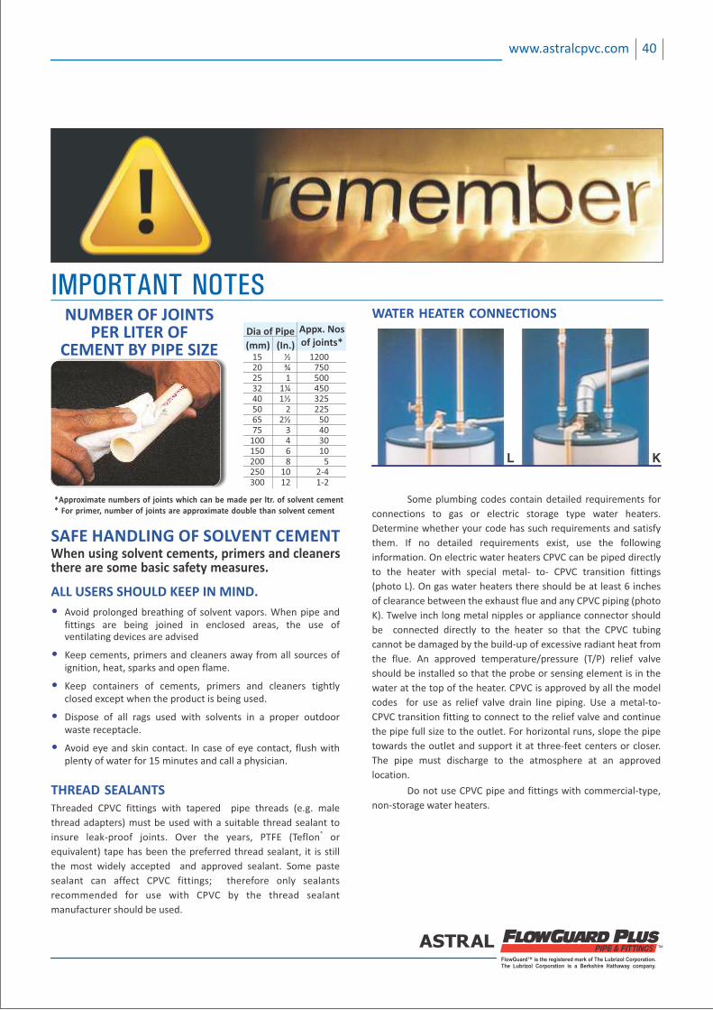
FlowGuard™ is the registered mark of The Lubrizol Corporation.The Lubrizol Corporation is a Berkshire Hathaway company.
WATER HEATER CONNECTIONS
L K
NUMBER OF JOINTSPER LITER OF
CEMENT BY PIPE SIZE
40www.astralcpvc.com
IMPORTANT NOTES
*Approximate numbers of joints which can be made per ltr. of solvent cement* For primer, number of joints are approximate double than solvent cement
Dia of Pipe Appx. Nosof joints*(In.)(mm)
15 ½ 1200 20 ¾ 750 25 1 500 32 1¼ 450 40 1½ 325 50 2 225 65 2½ 50 75 3 40 100 4 30 150 6 10 200 8 5 250 10 2‐4 300 12 1‐2
SAFE HANDLING OF SOLVENT CEMENTWhen using solvent cements, primers and cleanersthere are some basic safety measures.
ALL USERS SHOULD KEEP IN MIND.
• Avoid prolonged breathing of solvent vapors. When pipe and fittings are being joined in enclosed areas, the use of ventilating devices are advised
• Keep cements, primers and cleaners away from all sources of ignition, heat, sparks and open flame.
• Keep containers of cements, primers and cleaners tightly closed except when the product is being used.
• Dispose of all rags used with solvents in a proper outdoor waste receptacle.
• Avoid eye and skin contact. In case of eye contact, flush with plenty of water for 15 minutes and call a physician.
THREAD SEALANTSThreaded CPVC fittings with tapered pipe threads (e.g. male
thread adapters) must be used with a suitable thread sealant to ®insure leak‐proof joints. Over the years, PTFE (Teflon or
equivalent) tape has been the preferred thread sealant, it is still
the most widely accepted and approved sealant. Some paste
sealant can affect CPVC fittings; therefore only sealants
recommended for use with CPVC by the thread sealant
manufacturer should be used.
Some plumbing codes contain detailed requirements for
connections to gas or electric storage type water heaters.
Determine whether your code has such requirements and satisfy
them. If no detailed requirements exist, use the following
information. On electric water heaters CPVC can be piped directly
to the heater with special metal‐ to‐ CPVC transition fittings
(photo L). On gas water heaters there should be at least 6 inches
of clearance between the exhaust flue and any CPVC piping (photo
K). Twelve inch long metal nipples or appliance connector should
be connected directly to the heater so that the CPVC tubing
cannot be damaged by the build‐up of excessive radiant heat from
the flue. An approved temperature/pressure (T/P) relief valve
should be installed so that the probe or sensing element is in the
water at the top of the heater. CPVC is approved by all the model
codes for use as relief valve drain line piping. Use a metal‐to‐
CPVC transition fitting to connect to the relief valve and continue
the pipe full size to the outlet. For horizontal runs, slope the pipe
towards the outlet and support it at three‐feet centers or closer.
The pipe must discharge to the atmosphere at an approved
location.
Do not use CPVC pipe and fittings with commercial‐type,
non‐storage water heaters.

FlowGuard™ is the registered mark of The Lubrizol Corporation.The Lubrizol Corporation is a Berkshire Hathaway company.
42www.astralcpvc.com
NOTES :
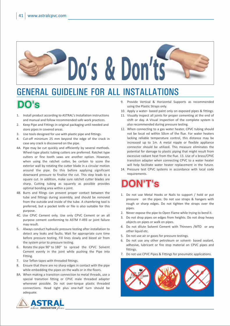
41 www.astralcpvc.com
GENERAL GUIDELINE FOR ALL INSTALLATIONS
1. Install product according to ASTRAL's Installation instructions
and manual and follow recommended safe work practices.
2. Keep Pipe and Fittings in original packaging until needed and
store pipes in covered areas.
3. Use tools designed for use with plastic pipe and fittings.
4. Cut‐off minimum 25 mm beyond the edge of the crack in
case any crack is discovered on the pipe.
4A. Pipe may be cut quickly and efficiently by several methods.
Wheel‐type plastic tubing cutters are preferred. Ratchet type
cutters or fine tooth saws are another option. However,
when using the ratchet cutter, be certain to score the
exterior wall by rotating the cutter blade in a circular motion
around the pipe. Do this before applying significant
downward pressure to finalise the cut. This step leads to a
square cut. In addition, make sure ratchet cutter blades are
sharp. Cutting tubing as squarely as possible provides
optimal bonding area within a joint.
4B. Burrs and filings can prevent proper contact between the
tube and fittings during assembly, and should be removed
from the outside and inside of the tube. A chamfering tool is
preferred, but a pocket knife or file is also suitable for this
purpose.
4C. Use CPVC Cement only. Use only CPVC Cement or an all
purpose cement conforming to ASTM F‐493 or joint failure
may result.
5. Always conduct hydraulic pressure testing after installation to
detect any leaks and faults. Wait for appropriate cure time
before pressure testing. Fill lines slowly and bleed air from
the system prior to pressure testing.
6. Rotate the pipe 90° to 180° to spread the CPVC Solvent
Cement evenly in the joint while pushing the Pipe into
Fitting.
7. Use Teflon tapes with threaded fittings.
8. Ensure that there are no sharp edges in contact with the pipe
while embedding the pipes on the walls or in the floors.
8A. When making a transition connection to metal threads, use a
special transition fitting or CPVC male threaded adapter
whenever possible. Do not over‐torque plastic threaded
connections. Head tight plus one‐half turn should be
adequate.
9. Provide Vertical & Horizontal Supports as recommended
using the Plastic Straps only.
10. Apply a water‐ based paint only on exposed pipes & fittings.
11. Visually inspect all joints for proper cementing at the end of
shift or day. A Visual inspection of the complete system is
also recommended during pressure testing.
12. When connecting to a gas water heater, CPVC tubing should
not be locat ed within 50cm of the flue. For water heaters
lacking reliable temperature control, this distance may be
increased up to 1m. A metal nipple or flexible appliance
connector should be utilized. This measure eliminates the
potential for damage to plastic piping that might result from
excessive radiant heat from the flue. 13. Use of a brass/CPVC
transition adapter when connecting CPVC to a water heater
will help facilitate water heater replacement in the future.
14. Pressure test CPVC systems in accordance with local code
requirements.
DO'sDO'sDO's
DON'T'sDON'T'sDON'T's1. Do not use Metal Hooks or Nails to support / hold or put
pressure on the pipes. Do not use straps & hangers with
rough or sharp edges. Do not tighten the straps over the
pipes.
2. Never expose the pipe to Open Flame while trying to bend it.
3. Do not drop pipes on edges from heights. Do not drop heavy
objects on pipes or walk on pipes.
4. Do not dilute Solvent Cement with Thinners /MTO or any
other liquid etc.
5. Do not use air or gases for pressure testings.
6. Do not use any other petroleum or solvent‐ based sealant,
adhesive, lubricant or fire stop material on CPVC pipes and
fittings.
7. Do not use CPVC Pipes & Fittings for pneumatic applications.
43 www.astralcpvc.com
NOTES :
FlowGuard™ is the registered mark of The Lubrizol Corporation.The Lubrizol Corporation is a Berkshire Hathaway company.
44www.astralcpvc.com
NOTES :
AFG/PC/005REV:07/10/14
desi
gn@
spec
trum
advt
.in
All information contained in this manual is given in good faith and believed to be accurate and reliable. But because of many factors which are outside our knowledge and control and affect use of product, no warranty is given or is to be implied with respect to such information, nor we offer any warranty of immunity against patent infringement. No responsibility can be accepted for any error, omissions or incorrect assumptions. Any specification can change without prior notice.
Follow us on : App Available on :
Authorised Distributor :
CIN : L25200GJ1996PLC029134
REGISTERED & CORPORATE OFFICE:
207/1, Astral House, B/h. Rajpath Club,
Off. S.G. Highway, Ahmedabad-380 059,
Gujarat, India.
Phone : +91 79 6621 2000
Fax : +91 79 6621 2121
E-mail : [email protected]
Website : www.astralcpvc.com
ASTRAL POLY TECHNIK LIMITED
ASTRAL IS ISO 9001:2008REGISTERED COMPANY
BRANCH OFFICES:Mumbai : Phone : (022) 2686 2227 E-mail : [email protected] Delhi : Phone : (011) 2616 8156 E-mail : [email protected] : Telefax : (080) 2661 7236 E-mail : [email protected] : Telefax : (040) 2790 0023 E-mail : [email protected] : Phone : (044) 4350 6384 E-mail : [email protected] : Phone : (0141) 2360 236 E-mail : [email protected] Lucknow : Phone : (0522) 2728 844 E-mail : [email protected] : Phone : (0484) 3328 156 E-mail : [email protected]
STRONG NAHIN, ASTRAL STRONG!! TM
OTHER PIPING SYSTEMS
| ASTM UPVC PIPING SYSTEM | uPVC DRAIN WASTE & VENT SYSTEM | LIGHT WEIGHT FOAMCORE UPVC PIPES |
| CPVC PIPING SYSTEM FOR INDUSTRIES | WIRE GUARD CONDUIT PIPES & FITINGS | ALCA PLAST SHOWER CHANNELS |
| CPVC PIPING SYSTEM FOR FIRE SPRINKLERS | CPVC-AL-CPVC MULTILAYER COMPOSITE PIPE |
| THE LEADING SOUNDPROOF SOIL & WASTE SYSTEM |
| uPVC PIPES FOR DRAINAGE & SEWERAGE APPLICATIONS | CLAMPS, HANGERS AND ELECTRICAL FLUSH BOXES |
| uPVC PIPE FOR AGRICULTURE & WATER TRANSPORT SYSTEM | uPVC CONVENTIONAL SYSTEM FOR SOIL WASTE & RAIN WATER |
| HEAVY METAL & LEAD FREE COLUMN PIPES FOR SUBMERSIBLE PUMPS |