asymmetric blowdown loads on pwr primary systems · 2013-09-13 · asymmetric blowdown loads on pwr...
TRANSCRIPT

NUREG-0609
Asymmetric Blowdown Loads on PWRPrimary Systems
Resolution of Generic Task Action Plan A-2
Manuscript Completed: November 1980Date Published: January 1981
S. B. Hosford, Task Manager, R. Mattu,R. 0. Meyer, E. D. Throm, C. G. Tinkler
Division of Safety TechnologyOffice of Nuclear Reactor RegulationU.S. Nuclear Regulatory CommissionWashington, D.C. 20555

ABSTRACT
The NRC staff, after being informed of newly identified asymmetric loadingsresulting from postulated ruptures of primary piping, initiated a genericinvestigation, Task Action Plan A-2. This investigation was limited topressurized-water-reactor (PWR) plants because of their higher primary systempressures and potential for larger asymmetric loads. The intent of the investi-gation was to develop a better understanding of this complicated phenomenonand then to develop acceptable criteria and guidelines for the staff to usefor evaluating plant analyses.
The staff has completed its investigation and concludes that an acceptablebasis is provided in this report for performing and reviewing plant analysesfor asymmetric LOCA (loss-of-coolant accident) loads. Guidelines and criteriawere developed for the following areas: evaluation of the loading transients,evaluation of the structural components, and evaluation of the fuel assembly.
The staff reviewed and approved computer programs and modeling techniquessubmitted by each PWR nuclear-steam-supply-system vendor for development ofthe subcooled blowdown- and cavity-pressure components of the loading transient.Audit models were developed to evaluate the structural computer programs andmodeling techniques. The audit evaluation has been completed and the methodshave been approved for the structural-analysis method submitted by Westinghousefor the Indian Point Unit 3 plant. Structural-analysis methods developed byBabcock and Wilcox and Combustion Engineering will be evaluated when theirplant analyses are submitted to NRC. Criteria and guidelines are provided toperform a detailed evaluation of the fuel assembly. Acceptance criteria arealso provided so deformed fuel-assembly spacer grids may be evaluated.
iii

CONTENTS
Page
ABSTRACT ......................................................... iii
1 INTRODUCTION ................................................ 12 BACKGROUND .................................................. 23 DEVELOPMENT OF LOADING FUNCTIONS ............................ 4
3.1 Internal Subcooled Blowdown Loads ...................... 7
3.2 Cavity-Pressure Loads .................................. 13
4 STRUCTURAL EVALUATION ....................................... 24
4.1 Primary-System Analytical Development .................. 244.2 Structural Acceptance Criteria ......................... 33
5 FUEL-ASSEMBLY EVALUATION .................................... 35
REFERENCES ....................................................... 36
APPENDIX A Task Action Plan A-2 .............................. A-iAPPENDIX B Status of of Operating Plant Evaluation ........... B-1APPENDIX C Characteristics of Pipe Breaks .................... C-1APPENDIX D Letters to Applicants/Licensees ................... D-1APPENDIX E Fuel-System Design (Appendix A to SRP 4.2) ........ E-1
LIST OF FIGURES
1. Pressurization of Reactor Annulus ........................... 52. Example of Asymmetrical Internals Load ...................... 63. Westinghouse Three-Loop PWR Loads Evaluation, Cold-Leg
Nozzle Break ................................................ 84. Uncoupled Versus Coupled Fluid-Structure Response ........... 105. Sample Nodal Model for a Reactor Cavity ..................... 186. Steam-Generator Support ..................................... 287. Typical Piping-Loop Model ................................... 298. Reactor-Pressure Vessel and Internals Model ................. 309. Core Model .................................................. 31
V.
ABBREVIATIONS
ACRS Advisory Committee on Reactor Safeguards
B&W Babcock and Wilcox
BWR boiling-water reactor
CE Combustion Engineering
CFR Code of Federal Regulations
CP construction permit
DOR Division of Operating Reactors, NRC
DSS Division of Systems Safety
EB Engineering Branch, DOR
ECCS emergency-core-cooling system
EDO Office of the Executive Director for Operations
EPN equivalent pipe networks
HDR superheated steam reactor
HEM homogeneous equilibrium
ISI inservice inspection
LOCA loss-of-coolant accident
NRC U.S. Nuclear Regulatory Commission
NSSS nuclear-steam-supply system
O.D. outside diameter
OL operating license
PWR pressurized-water reactor
RPV reactor pressure vessel
SAI Science Applications, Inc.
SRP Standard Review Plan
SRSS square root of the sum of squares
SSE safe shutdown earthquake
TAP task action plan
W Westinghouse Electric Coporation
vi
ASYMMETRIC BLOWDOWN LOADS ON PWR PRIMARY SYSTEMS:RESOLUTION OF GENERIC TASK ACTION PLAN A-2
1 INTRODUCTION
The NRC staff was informed on May 7, 1975 of newly identified asymmetricloadings which could act on the reactor's primary system. These asymmetricloadings result from a postulated double-ended rupture of the piping in theprimary coolant system. The magnitude of these loads is potentially largeenough to damage the supports of the reactor vessel, the reactor internals,and other primary components of the system. Because this newly identifiedphenomenon was complicated and not well understood at that time, the staffinitiated a generic study, Task Action Plan (TAP) A-2, to gain a better under-standing of these loads and to develop criteria for an evaluation of theresponse of the primary systems in pressurized-water reactors (PWRs) tothese loads.
The staff investigation, TAP A-2, was limited to primary systems of PWRs.Although similar loads associated with a postulated rupture of piping inprimary systems in boiling-water reactors (BWRs) are expected to occur, theoverall safety significance is considered to be much less because of the loweroperating pressures in primary systems in BWRs. If necessary, a staff programto resolve this issue in BWR plants will be considered, once the evaluation ofPWR plants is completed.
This investigation was concerned primarily with the loading phenomenonresulting from a postulated rupture of the piping in a primary loop. Althoughthey act on the primary system, additional loadings, such as thermal andseismic, are not the object of this investigation nor are they included inthis report. The results of the asymmetric loss-of-coolant accident (LOCA)evaluation must be combined with other loading responses, as appropriate, byapplicable staff-design requirements.
Concurrent with the staff investigation, licensees of PWR plants were notifiedby letter (see Appendix D) that an evaluation of their primary system forasymmetric LOCA loads would be required.
The staff investigation (TAP A-2) has been completed. Criteria and guidancefor conducting an evaluation for asymmetric LOCA loads were developed in thisstudy and are included in this report. In addition, the staff has provided anacceptable basis (provided in this report) for the evaluation and review ofthe response of PWR primary systems to asymmetric LOCA loads.
The report is organized in the same way as is a typical evaluation or review.Section 2 provides a detailed discussion about the nature of these loads onthe primary system, as well as a chronology of staff actions. Section 3offers a detailed discussion of the analytical development of these loads. InSection 4 a discussion of the structural analysis is found, and Section 5details the fuel-assembly evaluation.
1

2 BACKGROUND
On May 7, 1975, NRC was informed by the Virginia Electric and Power Companythat in the original design of the support system for reactor vessels forNorth Anna Units 1 and 2, neither Westinghouse nor Stone and Webster hadconsidered an asymmetric loading on the reactor vessel supports resultingfrom a postulated rupture of reactor-coolant piping at a specific location(for example, the nozzle of the reactor vessel). In the event of a postu-lated instantaneous, double-ended, offset rupture at the vessel's nozzle,asymmetric loading could result from forces induced on the reactor internalsby transient differential pressures across the core barrel and by forces onthe vessel caused by transient differential pressures in the reactor cavity.With the advent of more-sophisticated computer programs and the developmentof more-detailed analytical models, it became apparent that such differentialpressures, although of short duration, could place a significant load on thesupports of the reactor vessel and on other components, possibly affectingtheir integrity. This potential safety concern, first identified during thereview of the North Anna facilities, was determined to have generic impli-cations for all PWRs.
Upon closer examination of this situation, it appeared that postulated breaksin a reactor-coolant pipe at nozzles of reactor pressure vessels (RPVs) werenot the only area of concern, but that other pipe breaks in the reactor coolantsystem could cause internal and external transient loads to act upon both thereactor vessel and other components. For the postulated pipe break in thecold leg, asymmetric pressure changes could take place in the annulus betweenthe core barrel and the vessel. Decompression could take place on the side ofthe RPV annulus nearest the pipe break before the pressure on the oppositeside of the RPV changed. This momentary differential pressure across the corebarrel could induce lateral loads both on the core barrel and on the reactorvessel. Vertical loads could also be applied to the core internals and to thevessel because of the vertical flow resistance through the core and asym-metric axial decompression of the vessel. Simultaneously, for breaks in RPVnozzles, the annulus between the reactor and biological shield wall couldbecome asymmetrically pressurized, resulting in a differential pressure acrossthe reactor vessel causing additional horizontal and vertical external loadson the reactor vessel. In addition, the reactor vessel could be loadedsimultaneously by the effects of strain-energy release and blowdown thrustat the pipe break. For breaks at reactor vessel outlets, the same type ofloadings could occur, but the internal loads would be predominantly verticalbecause of the more-rapid decompression of the upper plenum. Similar asym-metric forces could also be generated by postulated pipe breaks located atthe steam generator and reactor-coolant pump. Therefore, the scope of thisproblem was not limited to the vessel support system itself.
On October 15, 1975, the NRC staff sent out letters surveying all of theoperating PWRs (Ref. 1) and determined from the survey responses that theseasymmetric loads had not been considered in the design of any PWR primarysystems.
In June 1976, the NRC requested (Ref. 2) all operating PWR licensees toevaluate the adequacy of reactor system components and supports at theirfacilities, with respect to these newly identified loads.
.2

In response to our request, most licensees with Westinghouse plants proposedto augment the inservice inspection (ISI) (Ref. 3) of the weld area betweenreactor-vessel nozzle and safe-end in lieu of providing an evaluation ofpostulated piping failures. In September 1976, licensees with CombustionEngineering (CE) plants submitted a probability study (prepared by ScienceApplications, Inc. (SAI)) (Ref. 4) in support of their conclusion that apipe break at a particular location (vessel nozzle) was so unlikely to occurthat no further analysis was necessary. A similar study was conducted bySAI for Babcock and Wilcox (B&W) plants in September 1977 (Ref. 5). Whenthe Westinghouse and (Ref. 3) CE owners-group reports were received inSeptember 1976, NRC formed a special review task group to evaluate thealternative proposals. In addition, EG&G Idaho, Inc., was contracted toperform an independent review of the SAI probability study submitted forthe CE owners group.
This review effort resulted in a substantial number of questions which havebeen provided to representatives of each group. Based on the nature of thesequestions, the NRC staff did not accept those reports as resolving theasymmetric LOCA-load generic issue. Based on NRC review, the staff concludedthat a sufficient data base did not exist within the nuclear industry to pro-vide satisfactory answers. Several long-term experimental programs would berequired to provide much of this information. Although the probability studysubmitted in September 1977 by SAI (Ref. 5) for certain B&W owners did respondto some of these questions, NRC staff determined that the more fundamentalquestions still remained unanswered.
A second and equally important reason for not accepting probability/ISIapproaches as a solution concerned our need and industry's need to obtain abetter understanding of the problem. We considered it essential that anunderstanding of the important breaks and associated consequences be knownbefore applying any remedy--be it pipe restraints, probability, ISI, or somecombination of these measures.
Upon reaching these conclusions, NRC staff initiated an inhouse investigationof this phenomenon (TAP A-2) (see Appendix A) and notified each PWR licensee(January 25, 1978) (see Appendix D) of NRC's requirement to have an evaluationof their facilities for these loads.
3

3 DEVELOPMENT OF LOADING FUNCTIONS
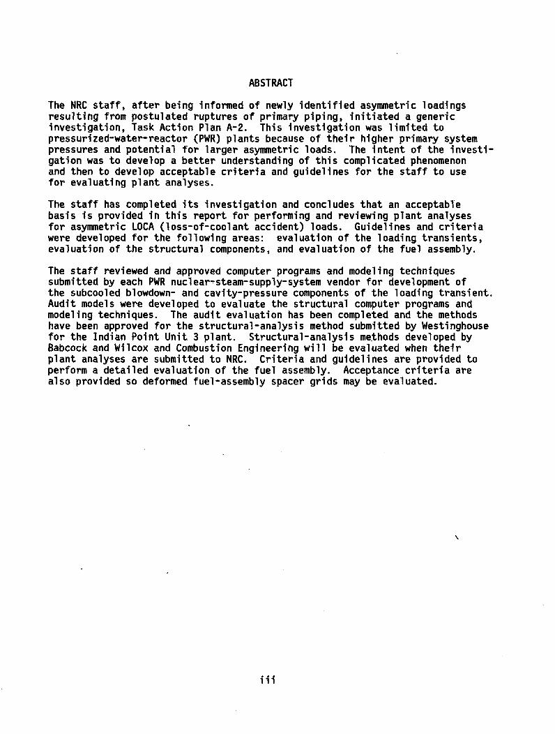
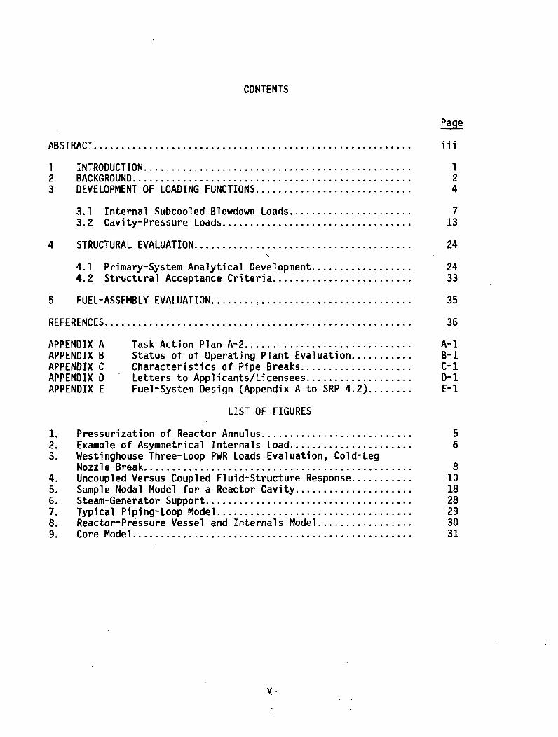
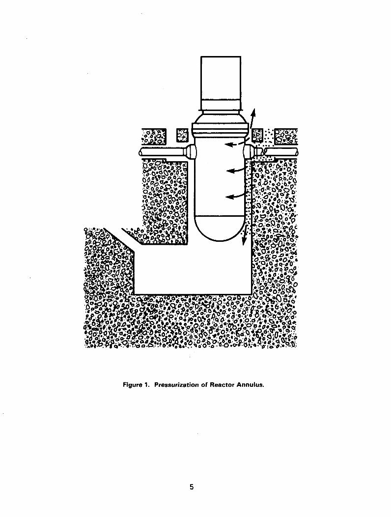
The first consideration in conducting an evaluation of the primary system forLOCA loads is to define and develop the loading transients associated with thepostulated pipe rupture. The loading transients depend on the postulatedbreak conditions, the postulated break locations, and on the operating condi-tions and geometry of the system. Typical loads acting on the reactorpressure vessel and internals are illustrated in Figures 1 and 2. A summaryof the loading components follows.
(1) Subcooled Blowdown Loads--Dynamic hydraulic forces occur throughout theprimary system due to the rapid subcooled depressurization of the system.These forces occur in the piping and component internals throughout thesystem.
(2) Cavity-Pressure Loads--A rupture of the primary-loop piping at a compo-nent nozzle can pressurize the cavity between the vessel (reactor-pressure vessel, steam generator, or reactor-coolant pump) and the cavitywall. Lateral and vertical forces are exerted on the component from thiscavity pressurization.
(3) Jet Impingement and Jet-Thrust Loads--Jet impingement and thrust loadsalso act on the primary system at the break location.
(4) Strain-Energy-Release Loads--The pipe rupture is postulated to occurduring normal operating conditions when the strain energy has built up inthe system. Some of this strain energy is released when the ruptureoccurs.
Typically, the strain-energy-release loads are determined by applying thesteady-state, normally operating, hydraulic loads and the forces thatresult from the weight of the structure in a static analysis of theintact system. For this static analysis, snubbers are assumed to beinactive. The steady-state displacements from this static analysis arethen used as initial conditions for the dynamic analysis where the brokenleg is disconnected from the vessel and allowed to move, and the snubbersare active.
All of the loading conditions discussed must be included in the evaluation ofthe primary system. These loads provide the information needed to evaluatethe dynamic response of the supports of the reactor-pressure vessel, thereactor-core structures, and the primary-coolant loop and its loop components.A detailed discussion of the subcooled blowdown (hydraulic) and cavity loadsis provided in Sections 3.1 and 3.2.
4
;. M76.
Figure 1. Pressurization of Reactor Annulus.
5
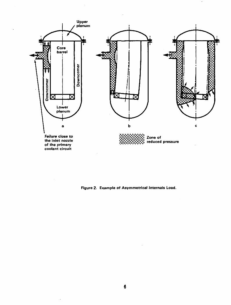
Upperplenum
bc
Zone ofreduced pressure
Failure close tothe inlet nozzleof the primarycoolant circuit
Figure 2. Example of Asymmetrical Internals Load.
6

3.1 Internal Subcooled Blowdown Loads
This section describes the procedures currently used by NRC to evaluate themethods utilized in a submittal for the calculation of the hydrodynamic load-ings on a reactor-coolant system undergoing a postulated LOCA.
Development of these loads involves several steps:
(1) The first step in the development of these loads is the determination ofthe transient pressure and velocity distribution throughout the system,using an appropriate thermal-hydraulic, computer program.
(2) The second step involves the conversion of these transient pressure andvelocity data into equivalent transient forces throughout the primarysystem. The transient forces developed in these two steps are thenincluded, along with the remaining LOCA loads, in a time-history struc-tural analysis of the primary system.
The staff has reviewed and approved Westinghouse (Ref. 6), Babcock and Wilcox(Ref. 7), and Combustion Engineering (Ref. 8) topical reports for the develop-ment of these hydrodynamic loads. The procedures and acceptance criteria usedby the staff for those reviews are discussed in Sections 3.1.1 through 3.1.4.
3.1.1 General Review Procedures
NRC staff review covers the analytical methods used by the licensee for theevaluation of the PWR primary-coolant system subjected to a LOCA with emphasison the subcooled, transition, and early saturation periods of the decompres-sion transient. It is during this timespan, on the order of 0.05 to 0.20seconds, that the induced hydraulic loads are greatest. The analytical methodsused must account for the acoustic wave phenomenon associated with the sub-cooled blowdown, the transmission, and the reflection of pressure wavesthroughout the system.
Modeling of the vessel's downcomer region is of major importance to thisreview. The application of current, one-dimensional computer programs to thecalculation of the multidimensional pressure field of the downcomer annulus isgiven significant attention. It is this pressure field which has the greatestinfluence on the lateral loads on the reactor vessel, core-support barrel, andfuel assemblies.
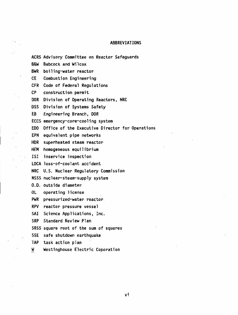
Figure 3 provides a summary of the effects of modeling on the predictedhydraulic loads. A Westinghouse three-loop plant was analyzed using the NRCstaff program WHAM/MOD-007. Two models were used; one was similar to theWestinghouse model, and the other was developed by the staff for coarse- andfine-noding comparisons, respectively. Also shown in Figure 3 is the effecton the calculated results of increasing the break-opening time.
In principle, the effects of a sudden decompression of a PWR primary systemcan be determined by a straightforward calculation considering the LOCApressure wave and its resulting interaction with internal structures of the
7

m
.13
0
0
SOLID LINES ARE FIT TO WESTINGHOUSE MODELDASHED LINES ARE FIT TO STAFF MODEL
BREAK AT COLD LEG NOZZLE
to'
-1B
Up
- -" LEGEND0= WESTINGHOUSE MODEL 1 MSEC BREAKSA= WESTINGHOUSE MODEL 10 MSEC BREAK0 = STfiPF MODEL I MSEC BREAKV = STAFF MODEL 10 MSEC BREAK
= MULTIFLEX DATA 1 MSEC BREAK( = MULTI FLEX DATA 10 MSEC BREAKM=MULTIFLEX RIGID WALL DATA
oA
0 100 200BREAK
300 400
SIZE (SQ.IN.)500 600
Figure 3. Westinghouse Three-Loop PWR Loads Evaluation,Cold-Leg Nozzle Break.
8

reactor. However, the physical process is not as straightforward. The result-ing motion of the core-support barrel to the decompression wave will feed backinto the local fluid pressure through the compressibility of the water. Theresulting hydrodynamic loads are reduced when this fluid-structure coupling isconsidered.
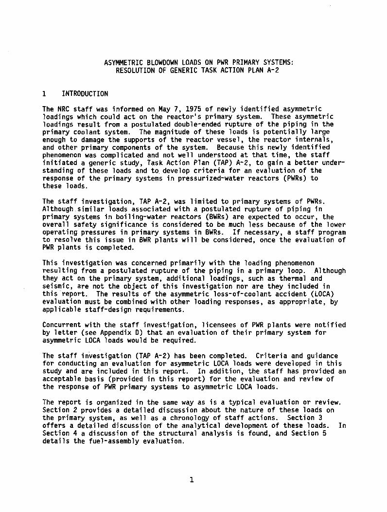
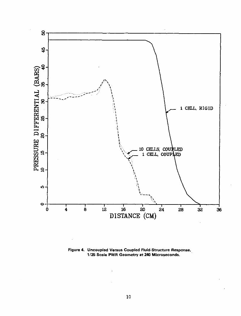
lhe SOLA-FLX computer program is being developed to supply the staff with atool for evaluating the coupled system. Figure 4, taken from Reference 9,shows the effect of the fluid-structure-coupled calculation. This figureillustrates the reduced loads associated with a coupled system and also showsthe effect of modeling the downcomer width. The results show that the rigid-wall assumption yields higher differential pressure, hence higher peak loads,with a higher frequency response than results in the coupled system; thedecompression wave travels faster in the uncoupled case. The thickness of thedowncomer annulus can be represented as a single cell and still yield a con-verged solution. The analytical development of a coupled fluid-structuresolution, if employed by the licensee, must also be reviewed.
The review procedure can be broken down into three major categories:(1) analytical development, (2) application and system modeling, and(3) computer-program verification. These items are addressed below inSections 3.1.2, 3.1.3, and 3.1.4, respectively.
3.1.2 Analytical Development
The staff typically reviews a number of areas as part of the licensee's analyt-ical development of the thermal-hydraulic computer program used for theevaluation of the subcooled blowdown loads. This review begins with the basicconservation equations of mass, momentum, and energy, and with the equation ofstate.
The assumption generally used for these analyses is homogeneity of the steam/water mixture. The subcooled, transition, and early saturated regimes of thetransient, where the homogeneous-fluid assumption is acceptable, are evaluated.The possibility of potential nonequilibrium effects is also considered in thereview.
The hydrodynamic loads are directly proportional to the differential pressuresapplied to a structure. If, as a result of nonequilibrium, the pressure atthe break plane falls below the saturation pressure of the fluid, prior to thedevelopment of two-phase-flow conditions, an increased loading could result.The effects of nonequilibrium would increase the loading on the core supportbarrel structure if this pressure "undershoot" is transmitted to the downcomer-annulus region.
The equation of state, the relationship between the fluid pressure and density,and the sonic or acoustic wave speed are also reviewed. The range of pressuresfrom operational pressure to the saturation pressure should be adequatelydescribed.
The assumptions used to reduce the basic conservation equations to the formused by the computer program are evaluated, with respect to the problem being
9
DI STANCE (CM)
Figure 4. Uncoupled Versus Coupled Fluid-Structure Response,1/25 Scale PWR Geometry at 240 Microseconds.
10

solved. The review includes the solution schemes used, convergence criteriaemployed, steady-state initialization, and the demonstration that conservationof mass, momentum, and energy are achieved. This last item is of primaryimportance when a one-dimensional computer is used to model a multidimensionalregion.
For those computer programs which include the fluid-structure coupling, themethod of incorporating the moving boundary into the conservation equations isreviewed.
The modeling of system components, such as the heat transfer in the reactorcore and steam generator, the pressurizer, the reactor-coolant pumps, andnonrecoverable energy losses are also considered.
The essential boundary conditions reviewed are the break-opening time and areacharacteristics. The history of the break-opening time and the break area inthe nuclear-steam-supply system (NSSS) primary piping system are plant specificand depend on such considerations as the location of the break, the stiffnessand mass of the piping system involved, and the type and location of piperestraints/supports being used. The break geometry postulated for this evalu-ation is a complete circumferential break of the primary coolant pipe. Appen-dix C of this report discusses characteristics of pipe breaks in more detail.
The discharge-flow model is an important aspect of this review. The discharge-flow model for the postulated break is the system-forcing function. As such,the treatment of the subcooled critical flow and potential nonequilibriumeffects must be properly accounted for in the development of the discharge-flowmodel.
3.1.3 Application and System Modeling
After the basic solution technique has been selected and equations have beendeveloped, the next stage of the review is oriented to using the computerprogram to evaluate the decompression transient. The model of the system usedto track transmission and reflection of the acoustic waves is reviewed.
The most significant aspect of the review is the modeling of the asymmetricpressure field in the downcomer annulus. At a minimum, a two-dimensionalpressure field is required to evaluate adequately the effects of the decom-pression waves as they travel into and around the downcomer annulus. Sincethe current generation of computer programs being used for this application isone dimensional, the application of the program to modeling multidimensionalregions must be reviewed.
Guidelines for the development of these models, referred to as equivalent pipenetworks (EPN) for the solution of the wave equation in characteristic form,may be found in References 10-12. In addition to the characteristic form ofsolution, the volume-flowpath approach (typical of codes such as RELAP) isalso used by some licensees. This approach has been reviewed and can bedemonstrated to be nearly equivalent to the vector-momentum equation governingnearly incompressible, low-speed flow for a multidimensional analysis.
11.

The acoustic-wave phenomenon, the transmission and reflection of the pressurewaves, is reviewed in terms of the computer-program method of solution. Forthe characteristic form, the transmission and reflection coefficients aredependent on the area, or the sum of the areas, through which the waves mustpass. In the volume-flowpath approach, these coefficients are replaced by theeffective inertia of a given flowpath connecting two volumes. Thesecoefficients are reviewed to assure that the wave transmission into the down-comer annulus is conservatively evaluated.
The sensitivity of the model to spatial representation, time-step size, and to
the various convergence criteria is also reviewed.
3.1.4 Code Verification
The last part of the review procedure is code verification, to verify theability of a computer program to predict the subcooled decompression phenomenonor acoustic-wave tracking. By comparing the licensee's program and modelingprocedure to selected problems and experimental data, significant modelingassumptions and features can be identified. In addition, the staff has augmen-ted the WHAM computer program (Ref. 13) for use in calculating these sameproblems and experiments. The program version used by the staff is WHAM/MOD-007(Ref. 14).
One of the major aspects of the review is the modeling of the downcomer annulusin at least two-dimensional form with the one-dimensional computer programs.Four sample problems were developed to aid in this review. They are described,along with the WHAM/MOD-007 analyses, in Reference 15. Analyses of theseproblems have also been performed by the staff's consultants at Sandia withthe CSQ computer program (Ref. 16). CSQ is a two-dimensional hydrodynamicprogram. Comparisons of the two sets of analyses demonstrate that the modelingtechniques used for the WHAM/MOD-007 analyses are in good agreement with thetwo-dimensional analyses.
Comparisons with applicable test data covering a wide range of system geome-tries and scales are also required as part of the code-verification review. Apartial list of acceptable test data is given in References 17-24. An HDR(superheated steam reactor) test facility (Ref. 24) analysis is required byall licensees as part of code verification. HDR is a nearly full-scale PWRgeometry which has been instrumented to obtain data during a subcooled decom-pression transient. Westinghouse, Babcock & Wilcox, and Combustion Engineeringwill be performing analyses of an HDR test to provide additional verificationof their methodologies.
Audit comparison of a PWR subcooled decompression analysis with the currentstaff models and computer program is also performed as part of the verificationprogram.
3.1.5 Summary
The staff review of the methodology used by the licensee to evaluate theresponse of the PWR to a subcooled decompression transient involves a numberof items important to the development of the hydraulic loads. Although each
12
analysis, including code formulation and code predictions of standard subcompart-ment problems. The licensee must also provide ancillary evidence, in the formof nodalization-sensitivity studies, to justify that the nodalization used inthe design-basis analysis is adequate for calculating the subcompartmentpressure transients. This requirement applies irrespective of the licensee'sadherence to the subcompartment guidelines contained in this report.
If the licensee has used a subcompartment computer code not previously foundacceptable by the staff, the staff will perform confirmatory analyses andcompare the results with those obtained by the applicant. Of primary interestare the differential pressures across subcompartment walls and the transientasymmetric pressure loads and their resultant location on enclosed components(such as the reactor pressure vessel). Evaluation of the adequacy of struc-tures and component supports should be based on the more severe of the loadingconditions calculated by the staff and the licensee following staff review andacceptance of the nodalization model and input data.
3.2.2 Analytical Methods
Conventional computer codes for subcompartment analyses utilize a number ofassumptions to facilitate the solution of the equations that describe thefluid-flow phenomena occurring within a subcompartment. Codes developed forcurrent use by the staff include the COMPARE code (Ref. 25) and the RELAP-4MOD 5 Code (Ref. 26). These codes predict (in a conservative manner) experi-mental data obtained from subcompartment tests. The principal assumptionsmade in currently accepted subcompartment-analysis codes are addressed below.
Containment subcompartments (for example, the reactor cavity) are analyzed bysubdividing them into a number of control volumes or nodes, that is, by nodali-zation of the subcompartment. This network of control volumes interconnectedby junctions or flowpaths describes the geometry of the subcompartment.
All thermodynamic properties within a control volume are assumed to be uniform;as a result, pressure distributions are represented by mean values. Further-more, control-volume cQnstituents--a two-phase, two-component, air-steam-watermixture--are assumed completely mixed at stagnation conditions and at the sametemperature. Thus, thermodynamic calculations are based on the assumption ofhomogeneous equilibrium. Additionally, the water expelled from the break isassumed to be completely entrained in the downstream flow mixture.
The subsonic rates of mass flow between control volumes are obtained by solvingthe incompressible one-dimensional momentum equation. Compressibility effectsin the vent flow are accounted for by adjusting vent-flow densities. Themomentum equation includes terms that account for inertia effects and pressureloss because of wall friction and form losses. The calculation of critical-mass flows between control volumes is based on either the frictionlessMoody correlation with a multiplier of 0.6 or the homogeneous equilibriummodel (HEM) correlation as outlined in Standard Review Plan Section 6.2.1.2.
It should be noted that the use of the HEM critical-flow correlation and theMoody correlation with a 0.6 multiplier has, in the past, been found acceptable
14
part may be considered on its own, the entire package must be considered indetermining the acceptability of the method and of the computer program. Thegoal is to provide assurance that the development of the pressure and velocityfields is applicable to the PWR geometry and that the loads obtained areconservative and consistent with safe plant-shutdown requirements.
3.2 Cavity-Pressure Loads
A subcompartment is a fully or partially enclosed volume within the containmentthat houses or adjoins high-energy piping systems and restricts the flow offluid to the main containment volume in the event of a postulated pipe rupture.Analyses of pressure transients in containment subcompartments involve theevaluation of the thermodynamic consequences of a postulated pipe rupture inthese compartmentalized regions of the containment. A spatially dependent,short-term-pressure transient will occur inside a subcompartment following apipe rupture, and pressure differentials across subcompartment structures andequipment will reach their maximum values generally within the first secondafter blowdown begins. The safety issue deals with the localized pressuregradients within a subcompartment and whether the subcompartment walls andcomponent supports for the primary reactor-coolant system can withstand thesegradients so that the reactor can be brought to a safe condition in the eventof a pipe rupture in the reactor system.
Therefore, subcompartment pressure analyses must be performed to determine theasymmetric pressure loadings on major components and on subcompartment walls.A discussion of the analytical methods, assumptions, and procedures for perform-ing these analyses is provided in this section. The discussion also includesa summary of the staff's review procedures and acceptance guidelines forevaluating the subcompartment analyses.
3.2.1 Review Procedures
The staff procedure for evaluating a subcompartment analysis will follow oneof two paths depending on the subcompartment-analysis code used by an applicant.
An expedited review is possible if a licensee has used a subcompartment codethat has been reviewed by the staff and found acceptable. In this instance,the staff will review the subcompartment-modeling procedures in light of therecommendations contained in this report. The staff will review the nodali-zation of the subcompartment and the input parameters used to determine theadequacy of the analytical model for calculating the pressure gradients andcomponent loads. If a licensee has adhered to these guidelines, sensitivitystudies are not required. NRC staff will also review the adequacy of themodel used to determine the component loads if it differs from the subcompart-ment model used to calculate pressure gradients.
If a licensee has used a subcompartment code not previously reviewed and foundacceptable by the staff, additional information must be provided to justifythe acceptability of the subcompartment analysis. In this regard, thelicensee should provide a description of the subcompartment code used for
13
because these models in general calculate low-mass-flow rates conservatively,over the spectrum of fluid conditions. The limiting loads on structures orequipment are for most cases determined by the loads induced by the rupture ofa high-energy line immediately adjacent to the structure or equipment inquestion. Therefore, critical-flow correlations which yield a low estimate ofmass flow will result in higher pressures in the vicinity of the break andlower pressures in regions further removed from the break. This translates tomaximizing the loads on the structures or components.
In those situations, however, where the component is most vulnerable to aloading induced by the rupture of a pipe not immediately adjacent to thecomponent or where the worst loading results from an overturning moment createdby loads away from the break, it is incumbent upon the designer to considerthe effects of a flow correlation which would yield corresponding high valuesof choked flow.
Additionally, the critical-flow models employed in state-of-the-art codes areunable to mechanistically model vena contracta effects. Therefore, the licenseeshould demonstrate that the vena contracta effects are unimportant to theanalysis or that this phenomenom is adequately treated in the flow calculation.
In summary, the staff will require that subcompartment analysis codes that areused for calculating transient pressure gradients incorporate the followingfeatures:
(1) Thermodynamic capabilities of mixture of air, steam, and water
(2) Homogeneous equilibrium of control-volume constituents
(3) Complete water entrainment for the determination of flow mixtures
(4) Subsonic flow calculations based on the incompressible momentum equation,including terms for:
(a) temporal change of momentum
(b) pressure loss from friction, area change, turning losses, and
(c) compressibility effects (variation of upstream density)
(5) Vent-flow checks based on selection of minimum flow calculated fromsubsonic calculation and critical-flow calculation
(6) Critical-flow calculation based on the HEM correlation or the Moodycorrelation with a 0.6 multiplier
Subcompartment Modeling--Subcompartment modeling involves the nodalizationof the physical region to be analyzed and the calculation of the requisiteinput data describing the nodalization arrangement for use in computer-codeanalyses. In this regard, the following topics need to be discussed:
15
(1) Subcompartment nodalization
(a) general nodalization procedures
(b) nodalization of blowdown volume(s)
(2) Subcompartment-code input data
(a) control-volume data
(b) junction-flowpath parameters
(c) time steps and blowdown data
Md) insulation considerations
(3) Force and moment calculations
3.2.2.1 Subcompartment Nodalization
Subcompartment nodalization is the subdividing of a subcompartment into anetwork of control volumes or nodes to assure an accurate prediction of thetransient-pressure response within the subcompartment. Consequently, thestaff's review of subcompartment analyses will include an evaluation of thebasis for nodalization of a subcompartment. The following discussion willaddress the general procedure for nodalization of a containment subcompart-ment, with special emphasis on the reactor cavity, which is the annular volumebetween the reactor vessel and the primary shield wall. Since it is not feas-ible to prescribe an acceptable, specific nodal arrangement applicable to allconfigurations of the reactor cavity, nodalization in the reactor cavity willbe discussed in detail to identify a modeling technique that will result inacceptable nodalization. The recommendations on subcompartment nodalizationare based on a study (Ref. 27) of several different designs of reactor cavities;this study investigated the sensitivity of the results to nodalization arrange-ments and other subcompartment-code input parameters.
General Nodalization Procedures--The nodalization of a subcompartment shouldrepresent, as much as practicable, the physical geometry and flowpaths in amanner that is consistent with the assumptions used in the subcompartment-analysis code. Boundaries between control volumes, which represent junctionsor vent paths, should be located at physical discontinuities where geometricinfluences are expected to create pressure differentials. In the subcompart-ment of a reactor cavity, there are many geometric variations that meritattention when developing the nodalization model. Examples of these arelisted below:
(1) Nozzles and piping of reactor vessels (for example, hot leg, cold leg,core flood line)
(2) Supports of reactor vessels
16

(3) Instrumentation tubes (for example, neutron detectors)
(4) Shielding devices (for example, shield blocks, plugs, shield ring, orshield tank)
(5) Variations in diameter of reactor vessels
(6) Variations in profile of primary shield wall
(7) Entrances and exits of penetration of shield wall
In addition to nodalization in regions where there are flow-area changes, itis also necessary to define nodal boundaries and, hence, junctions in regionsof constant cross-sectional area so as to account for frictional or inertialeffects which may create significant pressure losses. These frictional effectsinclude wall friction (fl/d) and turning losses.
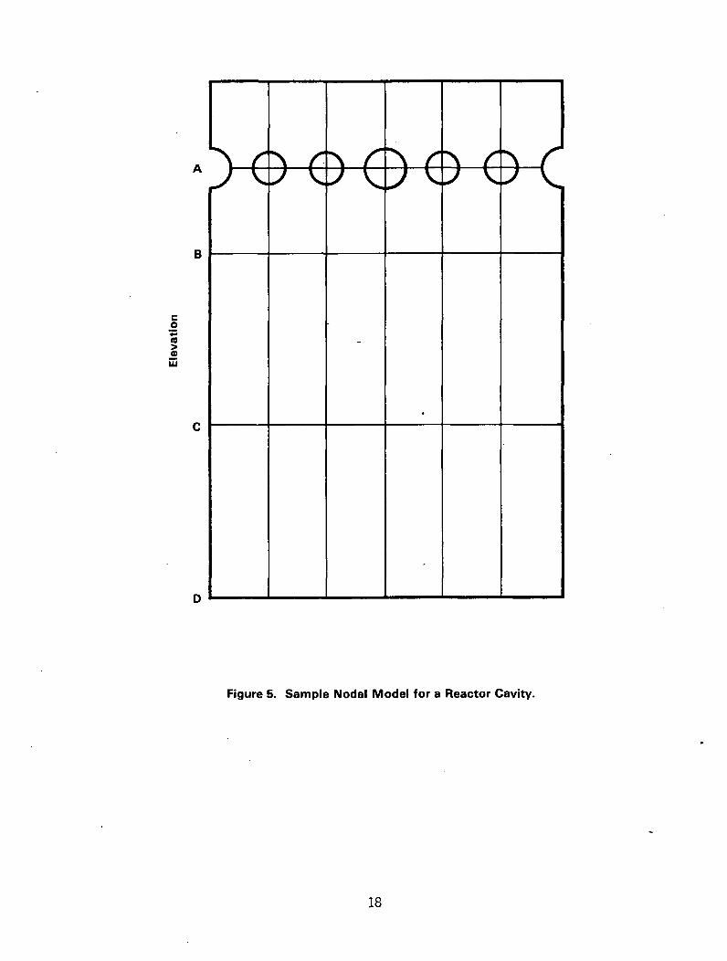
A sample nodal model for a reactor cavity is shown in Figure 5. The reactorcavity as shown is folded out to represent the entire 3600 circumferentialspan. The nodalization in Figure 5 was developed for design of a reactorcavity where only two geometric discontinuities were assumed to exist; namely,the flow-area change past the hot and cold legs of the reactor-coolant systemand the variation in flow area encountered at the location of the change indiameter of the reactor vessel. These two geometric influences result inhorizontal nodal boundaries at elevations A and B. The reason for includingthe horizontal boundary at elevation C was to permit a more accurate calcula-tion of the pressure gradient in the long, constant-area, annular region belowthe nozzles of the reactor pressure vessel. The boundary at elevation C isestablished at the midpoint between elevations B and D. The junctions at thebottom would correspond to the area change in flowing to the lower reactorcavity. The top boundaries would represent either a closed top or area changefor flow to volume(s) above the annulus of the reactor cavity.
Sensitivity studies (Ref. 27) show that the horizontal boundary at elevation C(shown in Figure 5) can be eliminated for certain cavity designs, when theboundary is established in the absence of geometric restrictions. Thesestudies also showed that the resultant forces and moments (calculated about ahorizontal axis through the nozzles--elevation A) changed by less than 5%.However, NRC is unable to conclude that such consolidation of nodes is uniformlyacceptable for all cavity designs, since the impact of such consolidationdepends on specific cavity dimensions and flowpaths. Therefore, an applicantshould demonstrate a similar insensitivity by performing noding studies topreclude any need for this level of nodalization for a specific plant appli-cation.
The above discussion dealt with the criteria for establishing horizontal nodalboundaries in a model of a reactor cavity. In establishing vertical boundariesto account for pressure differentials created by circumferential flow aboutthe reactor pressure vessel, attention should be directed again at modelinggeometric discontinuities. For the design of the reactor cavity representedin Figure 5, the only geometric variations in the circumferential directionare those created by the piping of the coolant system. Therefore, the control
17
U I -P - - I I -
A P I
-
I -U-----4-- 4 ~-e- 4 ---- 4 I -4------4- I
IB
0o-
S
C
D - - - - --
Figure 5. Sample Nodal Model for a Reactor Cavity.
18
volumes in Figure 5 encompass equal 600 segments about the reactor cavityregion. This same level of noding detail was retained in areas located awayfrom the nozzle region to adequately account for inertia and frictional effects(including wall friction and turning loss). Also, the greater degree ofnodalization reduces the impact of the typical computer-code assumption thatflowpaths are one-dimensional in nature. Cavity designs which include restric-tions to circumferential flow such as support columns or instrument tubes ofthe pressure vessel should be modeled so that nodal boundaries reflect thepresence of these restrictions.
Sensitivity studies (Ref. 27) have also been performed to evaluate the impactof the level of detail in circumferential nodalization. These studies demon-strated that nodalization could be made much coarser; that is, fewer circumferen-tial nodes, without substantial changes in the calculated peak loads andmoments on the reactor vessel. However, recognizing that sensitivity tonodalization detail will depend upon plant-specific geometry, it is recommendedthat circumferential noding for a design-basis model should include verticalboundaries through all nozzles of reactor pressure vessels for the height ofthe reactor cavity. Sensitivity studies on a specific plant may be performedby applicants in order to demonstrate acceptability for a model with lessdetail.
There are alternative approaches to development of an acceptable nodalizationarrangement for subcompartment analysis of the reactor cavity. One approachwould be to model the reactor cavity with detailed nodalization accounting forall obstructions, and resolution of detail in large, constant-area regions inthe manner described above. In this case, if an approved subcompartment-analysis is used, further sensitivity studies are not required.
Another approach would be to model the cavity in less detail, but account forall pressure losses, and provide sensitivity studies demonstrating the accept-ability of the design-basis model. Such sensitivity studies must compare theresults of interest, whether it be the loading on subcompartment walls or theforces and moments on components. These studies may be performed on a modelof either the plant under study or another plant having the same reactorcavity configuration and approximately the same dimensions.
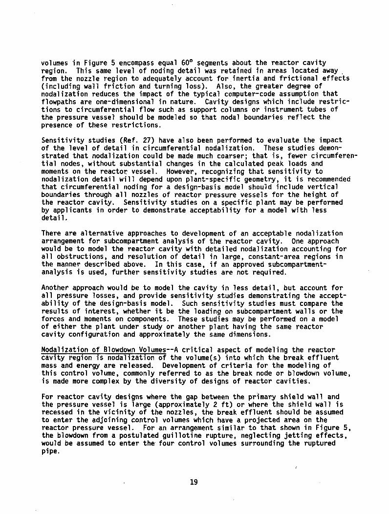
Nodalization of Blowdown Volumes--A critical aspect of modeling the reactorcavity region is nodalization of the volume(s) into which the break effluentmass and energy are released. Development of criteria for the modeling ofthis control volume, commonly referred to as the break node or blowdown volume,is made more complex by the diversity of designs of reactor cavities.
For reactor cavity designs where the gap between the primary shield wall andthe pressure vessel is large (approximately 2 ft) or where the shield wall isrecessed in the vicinity of the nozzles, the break effluent should be assumedto enter the adjoining control volumes which have a projected area on thereactor pressure vessel. For an arrangement similar to that shown in Figure 5,the blowdown from a postulated guillotine rupture, neglecting jetting effects,would be assumed to enter the four control volumes surrounding the rupturedpipe.
19
There are some designs in which the location of the terminal ends of thepiping of the reactor-coolant system is within nodes or control volumes thatare away from the annular region of the reactor cavity. Thus, in the event ofa postulated pipe rupture, the blowdown effluent is assumed to enter a controlvolume inside the primary shield wall (for example, pipe-penetration volume)or otherwise radially removed from the annular space immediately adjacent tothe reactor vessel.
For models of reactor cavities where the break node is not assumed to bedirectly projected onto the reactor vessel, the applicant must clearlydemonstrate the acceptability of the nodalization in the vicinity of the pipebreak. This includes justification with sufficiently detailed drawings of theregion of the vent areas away from the break node.
In selecting the break node(s), consideration must be given to the potentialfor, and effects of, fluid jetting from the site of the pipe rupture. This isimportant for all reactor-cavity designs but especially in those configura-tions where the pipe rupture is postulated to occur within a primary shield-wallpenetration. For such designs the applicant must either justify that directjetting into the reactor-cavity annulus would not occur or include the effectof jetting in calculating the loading condition on the reactor vessel. Anacceptable approach is to demonstrate, if practicable, that pipe restraintswould limit lateral separation in the event of pipe rupture to less than thepipe thickness.
3.2.2.2 Subcompartment Code Input Data
The following is a discussion of the data that are required for input into thecomputer codes used in subcompartment analysis. The data can be described aseither control-volume data or flowpath data. Additional input parametersaddressed are time-step data, blowdown data, and assumptions regarding thetreatment of thermal insulation.
Control-Volume Data--The pertinent control-volume data are the free volume andthe initial temperature, pressure, and relative humidity of control volumes.Initial conditions should be selected, within the range of anticipated values,to conservatively predict the result of interest; that is, loads on structuresor loads and moments on primary system components.
The studies (Ref. 27) we have performed showed that the sensitivity to initialpressure, temperature, and relative humidity variations is insignificant (lessthan 5%). However, this study was done for a specific reactor cavity designand may not apply to other subcompartment (for example, steam-generator enclo-sure) analyses or analysis involving different reactor cavity designs.
Uncertainties in the calculated free volume of each node shall be applied insuch a way as to obtain the most severe loading condition of interest.
Flowpath Parameters--The flowpath data of interest in modeling a flowpathbetween control volumes typically include the flow area, loss coefficients,and the inertia term (L/A ft-1).
20
The flow area that is used as input to subcompartment codes should be based onthe minimum flow area between control volumes. This is consistent with thebasic premise of subcompartment nodalization which is to place boundaries atflow restrictions. Also, critical flow models are based on the minimum flowarea.
Uncertainties in flow areas should be applied in a manner that yields conserva-tive results of interest. For example, if one would calculate lateral loadson the reactor vessel, a low estimate of the flow areas should be used forflowpaths that relieve the pressure near the break, for example, circumferen-tial flowpaths. However, if the vertical location of the resultant lateralforce, that is, the moment, is of concern, then maximization of appropriateflow areas for vertical flow on the same side of the reactor vessel as thebreak should be considered.
If the subcompartment model includes vent areas that become available as aresult of fluid flow or pressurization effects after initiation of the accident,the following criteria apply:
(1) The modified flowpath parameters (for example, vent area, resistance) asa function of time or pressure after the break should be based on analysisof the subcompartment pressure response.
(2) Availability of vent areas resulting from pressure or flow effects shouldbe justified analytically or experimentally.
(3) The potential for, and effects of, missiles that may be generated duringthe transient should be evaluated.
Loss coefficients are conventionally used to account for total pressure lossesdue to changes in flow area, turning losses, and wall friction. Coefficientsof hydraulic loss are available in the literature; the most commonly usedcomprehensive itemization is found in Reference 28. Applicants should providea-discussion of the methods used to determine loss coefficients and a represen-tative sample calculation of the loss coefficients.
Consideration should be given to the direction of flow when selecting losscoefficients for a given flowpath, since values may change depending on thedirection of flow. If the analysis is done with a subcompartment code thatdoes not account for effects of flow direction, the specified flow directionthat is used as input must be verified by the analysis.
Attention should also be given to ensuring the consistency between the flowarea and loss coefficients that are used as input data. For loss coefficientsbased on an area other than that used as input to the code, the loss coef-ficients must be appropriately modified (by the ratio of the areas squared).It is recognized that loss coefficients used in subcompartment analyses arebased on hydraulic, steady-state flow and, as such, do not reflect considera-tion of the complexities associated with a compressible two-phase, two-component,transient-flow problem. However, based on the reactor-cavity studies (Ref. 27)NRC staff has performed to date, the sensitivity of reactor-cavity analysis to
21

the uncertainties associated with the steady-state, hydraulic loss coeffi-cients is small. Therefore, the current method of selecting loss coefficientsin subcompartment analysis of reactor cavities is judged to be acceptable.
Fluid inertia has a significant effect on the pressure gradients calculated insubcompartment analyses (Ref. 27). Inertia is typically accounted for by useof the geometric (L/A ft-1) as input, which results from, solution of themomentum equation. Currently, acceptable practice for calculation of theinertia term is outlined in Reference 27.
Time steps used to calculate the transient distribution of mass from the piperupture should be sufficiently small (a decrease in the time-step size shouldbe done with the aid of sensitivity studies on a specific plant or by compari-son with studies on similar plants).
3.2.2.3 Other Factors
Insulation Behavior Considerations--Thermal insulation on piping and vesselsmust be considered when performing subcompartment analysis. The relativeimportance of assumed insulation behavior is magnified for the reactor-cavityanalysis since thermal insulation may comprise a significant volume within thereactor-cavity annulus and the penetrations through the shield wall.
Assumptions related to postaccident insulation behavior must either be shownto be conservative or, if insulation behavior is treated mechanistically, suchbehavior must be justified analytically or experimentally.
In either case, the applicant must provide justification for the assumedbehavior of insulation and a detailed discussion of how insulation affectsvolumes and flow areas both in thereactor-cavity annulus and in those flow-paths away from the reactor cavity (for example, penetrations of the shieldwall).
Blowdown Mass and Energy--The driving potential for asymmetric pressure loadsis the blowdown from a postulated pipe rupture. The blowdown characteristicsare typically input to the subcompartment computer codes in the form of amass-flow addition rate as a function of time and a corresponding enthalpy- orenergy-addition rate as a function of time. On the basis of studies performedby the staff (Ref. 27) and a review of applicants' analyses, we find that theblowdown mass-and-energy release rates are important parameters in the calcula-tion of asymmetric loads and moments. Analyses have shown that the sensitivityof peak calculated loads and moments of reactor pressure vessels can be directlyproportional to the short-term mass-and-energy release rates. Therefore,subcompartment analysis should be based on conservatively derived blowdownmass-and-energy release rates.
In general, calculations of the mass-and-energy release rates for a LOCAshould be performed in a manner that conservatively establishes the containmentsubcompartment response. The analytical approach used to compute the mass-and-energy release profile for the first several seconds of blowdown for use insubcompartment analysis is acceptable if the volume noding of the piping
22

system is similar to those of an approved emergency-core-cooling-system (ECCS)analysis or if appropriate noding-sensitivity studies have been made. Thecomputer programs that are currently acceptable include SATAN-V (Ref. 29),CRAFT-2 (Ref. 30), CE FLASH-4A (Ref. 31), and RELAP4 (Ref. 32), when a flowmultiplier of 1.0 is used with the applicable choked-flow correlations for theabove computer codes. An alternate acceptable approach is to assume a constantblowdown profile using the initial conditions with the choked-flow correlationsin the above references.
3.2.2.4 Force-Moment Calculations
The calculation of forces and moments, as applicable, on components of reactorsystems or on subcompartment structures is the culmination of the subcompart-ment analysis and, therefore, requires the same detailed consideration as thatfor subcompartment modeling.
The following requirements apply to the translation of calculated pressuregradients into forces and moments.
(1) The subcompartment nodal model used for the calculation of forces andmoments should be the same model as that found acceptable for the calcu-lation of pressure gradients. If the model used to calculate forces andmoments is different from the model used to calculate pressure gradients,then the calculated forces and moments shall be shown to be equivalent tothose forces and moments that would have been calculated had the othermodel been used.
(2) Projected areas onto a curved surface shall be based on projected planarareas. Then multiplication of the projected area by the calculated nodalpressure gives the force acting normal to the surface through the areacentroid.
(3) Force calculations for components such as the reactor pressure vesselshall include loads resulting from differential pressures acting acrossthe vessel piping and nozzles.
23
4 STRUCTURAL EVALUATION
The structural evaluation of the primary system for asymmetric LOCA loadsinvolves the development of detailed finite element models, the application ofthe loading transients (discussed in Section 3) to these models, and finallythe assessment of the resulting structural response against appropriate accep-tance criteria. The finite element models required for this evaluation aretypically large and complex and may incorporate both nonlinear (geometric) andinelastic (material) modeling aspects. Based on these considerations, thestaff chose an audit approach to verify various modeling assumptions andsensitivity.
The staff evaluated six PWR primary systems both to gain a better understandingof the primary-system response and to develop the capability for performing anaudit of plant-specific analyses. The six plants chosen represented two fromeach NSSS vendor: one using conservative elastic-analysis techniques and oneincorporating inelastic-and nonlinear-analysis techniques. A detailed discus-sion of each of these six plant-audit calculations, listed below, is providedin References 33 through 38.
Westinghouse Lead Plants
North Anna 1--elastic analysis (Ref. 33)Indian Point 3--inelastic analysis (Ref. 34)
Combustion Engineering Lead Plants
San Onofre--elastic analysis (Ref. 35)St. Lucie 1--inelastic analysis (Ref. 36)
Babcock and Wilcox Lead Plants
Erie--elastic analysis (Ref. 37)Arkansas 1--inelastic analysis (Ref. 38)
A discussion of modeling considerations and review procedures for the struc-tural evaluation are-provided in Section 4.1 and structural acceptancecriteria, although not developed as part of this task action plan, are pro-vided in Section 4.2.
4.1 Primary-System Analytical Development
4.1.1 Modeling Aspects
Structural analysis of reactor primary coolant systems is performed todemonstrate that the plant can be safely shut down in the unlikely event of apostulated LOCA. Structural analysis for purposes of this discussion isdefined as the specification of mechanical response (loads, deflections, andstresses) of the primary coolant piping, major components and their supports,and reactor internals and fuel. Detailed finite element models are requiredto predict these mechanical responses accurately, although more-conservativesimplified techniques may be applicable in special cases.
24
Modeling techniques for this analysis are not unique. They vary depending onthe computer codes, the geometry, and the analytical assumptions. Primarysystems responses, in general, are nonlinear in nature due to geometrical gapsand various design characteristics of supports, such as cables which act inonly one direction. The analytical models may also require inelastic considera-tions to reflect material nonlinearities.
A single model representing the entire primary system and incorporating suffi-cient detail is not practical within current computer and economic limits.The structural analysis is, therefore, completed in phases in which theresponses from a general system model are used as input to detailed structuralmodels (subsystems) of critical parts of the primary system. The system modeltypically includes a representation of the reactor pressure vessel, its corebarrel,, the internals and fuel assemblies, the primary coolant piping, thesteam generator and supports, and the primary-coolant pump and supports.Typical subsystems which are evaluated using input from the systems model are:attached ECCS piping, detailed models of RPV and component supports, anddetailed evaluation of the fuel integrity.
Basically, the preceding paragraphs have been oriented toward a finite elementmodel of a single reactor system. Finite element representation of the primarycoolant system using a number of completely decoupled models may also consti-tute an acceptable approach. As an example, a reactor-coolant system could berepresented by the following three separate finite element submodels:
(1) Reactor vessel internals and vessel supports(2) Broken piping loop, components, and component supports(3) Intact loop, component, and component supports
If this approach is pursued, the interaction of the various submodels must beaccounted for in the evaluation.
A general discussion of modeling aspects is provided in this section as wellas a detailed discussion of one acceptable modeling technique (used by NRCstaff for the Indian Point 3 audit) to illustrate modeling considerations.
4.1.1.1 Vessels
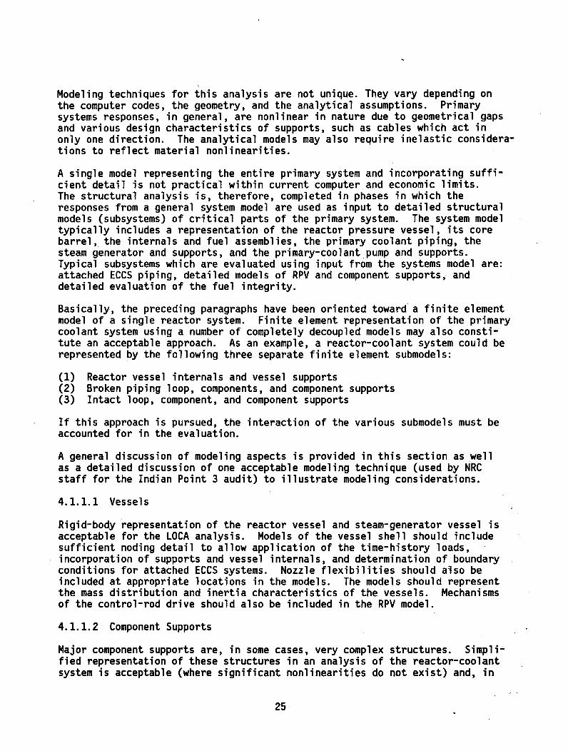
Rigid-body representation of the reactor vessel and steam-generator vessel isacceptable for the LOCA analysis. Models of the vessel shell should includesufficient noding detail to allow application of the time-history loads,incorporation of supports and vessel internals, and determination of boundaryconditions for attached ECCS systems. Nozzle flexibilities should also beincluded at appropriate locations in the models. The models should representthe mass distribution and inertia characteristics of the vessels. Mechanismsof the control-rod drive should also be included in the RPV model.
4.1.1.2 Component Supports
Major component supports are, in some cases, very complex structures. Simpli-fied representation of these structures in an analysis of the reactor-coolantsystem is acceptable (where significant nonlinearities do not exist) and, in
25
some cases, necessary. Constraints in the size of the finite element modelmay make it necessary to incorporate a simplified representation of the steamgenerator and pump supports.
In modeling the various component supports, substructuring may be a validmeans of reducing the size of the overall model. To explain the term "sub-structuring" as used in this report, consider the following example for a maincoolant pump with a complex structure or framework of beams comprising itssupport to the foundation. A separate analysis of the support structure canbe conducted with loads applied at the locations where the pump attaches toits support structure. If force versus deflection curves and moment versusrotation curves can be developed for this "substructured" support and the masscharacteristics (natural frequencies) can be reasonably represented, then thecomplex support system can be replaced with a simpler support system whoseload versus deflection, moment versus rotation, and mass characteristics arethe same as those for the complex system. The net result is then a simpler,smaller model for the system analysis.
4.1.1.3 Internals
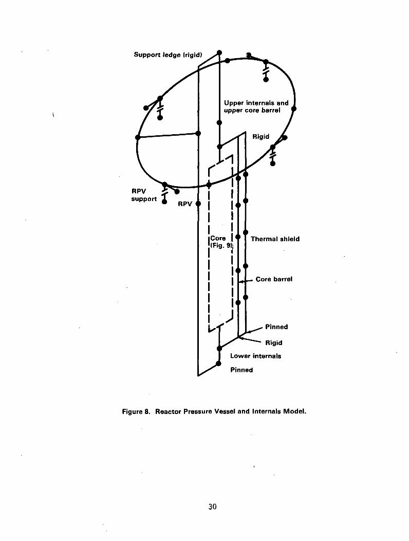
The goal of the internal portion of the system model is twofold; the first isto determine the structural response of the core barrel and core supports; thesecond is to provide appropriate input for a detailed evaluation of the fuel(discussed in Chapter 5). The internal structures and terminology may vary,depending upon NSSS vendor designs; but, in general, the internals modelshould include the following:
(1) Core barrel(2) Thermal shield(3) Core-support structure(4) Core(5) Upper plenum assembly(6) Guide-tube assembly
Modeling of these structures in the system model should include sufficientdetail to represent the mass distribution and inertia effect. Attentionshould be given to the review of interface areas (such as the core-barrel-to-RPV connection) which are part of the load path, to ensure an accurate model-ing expectation.
4.1.1.4 Primary Piping
Representation of the piping should be sufficiently detailed to calculate themaximum stress, permit representation of pipe supports, and provide input forstructural analysis of ECCS and other piping subsystems that connect to theprimary coolant system.
4.1.1.5 Indian Point Unit 3 Audit Model
A summary of the modeling techniques used for the Indian Point Unit 3 (Ref. 34)lead plant audit is provided to illustrate the modeling detail and development.The primary system of Indian Point Unit 3 is represented by an assemblage of
26
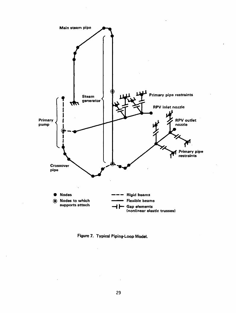
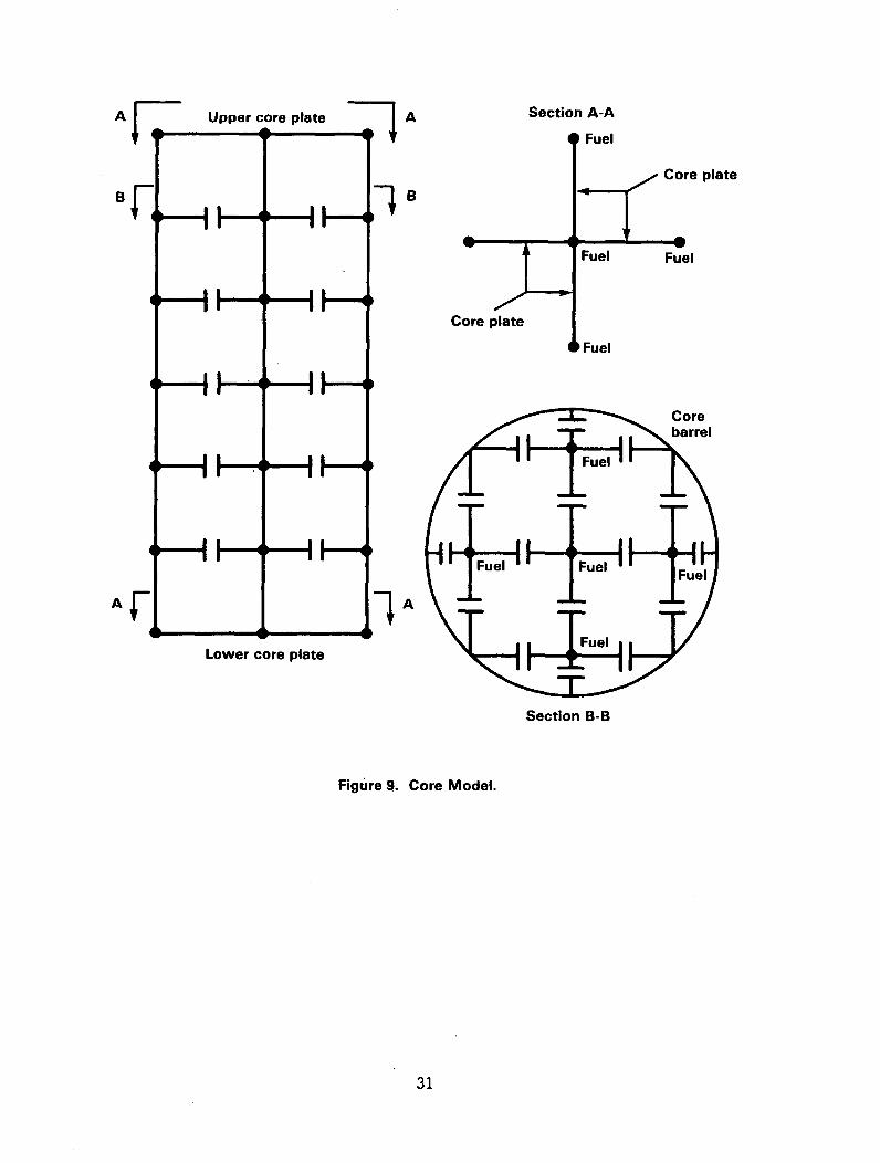
linear elastic, nonlinear elastic, and elastic-plastic truss and beam elements.Finite element models used in staff audit of Indian Point Unit 3 are represen-ted in Figures 1-9. As shown in Figure 6, the steam-generator supports arerepresented by equivalent beams analogous to the steam-generator supports.These equivalent structures were derived from the flexibility matrices andvibration modes of detailed support models. The primary piping loop models,Figure 7, consist of an elastic-plastic beam representation of the primarypiping with an elastic beam representation of the pump, steam generator, andmain steam piping. Figures 8 and 9 show the RPV and internals and core models.The RPV and internals are represented by elastic beams, and the core is repre-sented by elastic beams interconnected by nonlinear elastic truss elements orgap elements. With this model, the fuel, represented by elastic beams, isallowed to impact both the core barrel and adjacent fuel. The RPV supportsshown in Figure 8 are represented by a horizontal elastic-plastic truss ele-ment and a vertical nonlinear elastic or compression-only truss element. Theremaining structural components, the hot stops and snubbers on the steam-generator supports, the base restraints of the pump supports, the tie rods,and the primary piping restraints are represented by either nonlinear elasticor elastic-plastic truss elements.
4.1.2 Review Procedure
The structural evaluation of the primary system must include, as a minimum, ananalysis of the following:
(1) Reactor pressure vessel(2) Fuel assemblies, including grid structures(3) Control and rod drives(4) ECCS piping that is attached to the primary coolant piping(5) Primary coolant piping(6) Reactor-vessel, steam-generator, and pump supports(7) Reactor internals(8) Biological shield wall and neutron shield tank (where applicable)(9) Steam-generator compartment wall
The review and determination of the adequacy of a plant-specific analysis forasymmetric loads by the staff should include an assessment in the followingareas: the structural computer codes, the modeling techniques and assumptions,and the acceptability of the responses.
The structural computer codes and modeling techniques and assumptions arereviewed and approved as a package. Two approaches for performing this reviewhave been developed by the staff:
(1) Review and approve a general analytical technique applicable to more thanone plant.
(2) Perform an independent audit of a specific plant evaluation.
27

Unrestrainedmotion direction
SnubberHot stop
but free to slide vertically* Nodes
® Nodes to which steamgenerator attaches
Nodes to which tie rodsattach
-1 j-- Gap elements(nonlinear elastic trusses)
-Ag- Elastic plastic trusses
-F Flexible beams
. -- -Rigid beams
T'To RPV
Rigid connection
To pump
Unrestrainedmotion direction,a-l
Snubber
Hot stop
Figure 6. Steam Generator Support.
28
Main steam pipe
4 bteagene
Primarypump
I
Crossoverpipe
Iv
0 Nodes® Nodes to which
supports attach
mrator
Primary pipe restraints
RPV inlet nozzle
RPV outletnozzleK>VIO
r Primary piperestraints
Rigid beams
-Flexible beams
1 Gap elements(nonlinear elastic trusses)
Figure 7. Typical Piping-Loop Model.
29
Support ledge frigid)
Thermal shield
0- ' Rigid
Lower internals
Figure 8. Reactor Pressure Vessel and Internals Model.
30
BF1V
Upper core plate-I A
-1B
Section A-A
Fuel
Core plate
tJ
I
I
IH
,I "- --l-
IIF-
" "-4--
"• II
Core plate
Fuel
IFuel
Fuel
Ai • I
4 I
AI A
Lower core plate
Section B-B
Figure 9. Core Model.
31
4.1.2.1 General Analytical Technique
Review and approval of a general analytical technique is applicable when anumber of plants are evaluated using the same computer codes and modelingconsiderations. This approach was chosen by the majority of operating plantswho engaged their NSSS vendors to perform these evaluations. The review isperformed in two steps: first, the general analytical technique is reviewedand approved and, second, each plant analysis is reviewed for consistency withthe approved general approach.
Typically, the general analytical technique consists of the structural computercodes, the analytical modeling, and the result from a representative analysis.The representative analysis may be of a specific plant or a generic plant andshould identify selected user options in the computer code and provide themodeling detail and assumptions. The staff typically determines the accept-ability of the general analytical technique by performing an independent auditevaluation, discussed in Section 4.1.2.2. The audit evaluation may not berequired if sufficient noding-sensitivity studies are performed on the struc-tural models and the computer codes have been verified as acceptable by thestaff.
The staff has currently reviewed and approved the general analytical approachsubmitted by Westinghouse for the Indian Point 3 nuclear plant (Ref. 39).Details of the audit evaluation are presented in an EG&G report (Ref. 34).The staff has developed audit models for both a Combustion Engineering plant(Ref. 34) and a Babcock and Wilcox plant (Ref. 38). Their general analyticalapproach will be evaluated when their respective plant reports are submittedfor staff review.
Basically, evaluation of each plant submittal involves reviewing the structuralmodels for detail and completeness and applying the structural computer codesfor consistency with the approved general approach. Review of the modelingshould include the relative noding detail, the boundary conditions, and thenoding assumptions. The computer code version and user-specific optionsshould also be verified to be consistent with the approved approach.
4.1.2.2 Independent Staff Audit
The second approach is to perform an independent audit of the plant using astaff-approved computer code and staff-developed models. Plant analyses whicheither do not use an approved general analytical approach or modify an approvedapproach significantly, may require an independent staff audit. Exceptionsmay exist where sufficient supporting documentation is provided to enable thestaff to make an evaluation. Review for acceptability is fairly simple inthis approach and typically requires a comparison of the response characteris-tics. The information required from the licensee to perform the audit issummarized below.
Piping--Geometric layout dimensions for piping centerline are required soconnectivity from the RPV to the steam generator (hot-leg segment), steam-generator-to-pump inlet (crossover segment), pump outlet to RPV inlet (cold-legsegment), can provide for proper interactions of the piping with its attached
32

components. Section properties for each segment of piping must be availablefrom the drawings so proper stiffness effects can be included. Materialslists for all segments should be provided along with normal operating condi-tions (pressure and temperature) for each segment. Pipe supports must be welldefined with regard to location and type (material, stiffness, load limit,behavior above load limit--failure versus constant load, action--one direc-tional only or either direction, geometric gaps).
Steam Generators--Generally, section properties of the shell must be availableso the effective stiffness of the steam generators can be modeled. Addition-ally, weights of steam-generator components should also be provided (upper andlower head tube sheets, tubes, water contained). Total weight of the steamgenerator (dry and including normal operation water) should be available toprovide reasonable mass distribution for the steam generator. Steam-generatorsupport details must also be available, including support-to-foundation inter-face to provide a useful form of input for the analyst.
Pumps--The weight (including water weight), center-of-gravity location, androtary inertia should be provided for the pumps in order to represent theireffects on the piping. Pump supports should be defined and located includingsnubbers and their behavior (that is, their physical characteristics: loadrating, behavior on exceeding rated load and failure load, and preload, ifany). For complex pump supports to foundation, details must be provided toallow mass and stiffness properties to be included for that part of thesystem.
Reactor Pressure Vessel--Details of the RPV shell must be available sincestiffness properties for the RPV are normally based on properties of the shellsection. Weights should be provided (including water weights and their distri-bution) to represent the proper mass distribution of the RPV. Support detailsand support-to-foundation details and information should be provided, as forsteam generators and pumps.
RPV Internals--Detailed and assembly drawings should be supplied so interac-tions of various, major internal components to the RPV can be modeled. Thesedrawings should include section properties and material properties for thefuel modules and internals of the core barrel. Weights for these componentsshould also be supplied. In addition, weights of core plates and of remaininginternals should be supplied, so proper mass distribution in the RPV can beincluded.
Water weights for the various regions inside the RPV and fuel frequenciesshould be supplied.
The final review consideration is the review of the structural response againstapplicable acceptance criteria (Section 4.2).
4.2 Structural Acceptance Criteria
The structural integrity of the primary system including the reactor pressurevessel, RPV internals, primary coolant loop, and components must be evaluatedagainst appropriate acceptance criteria to determine if acceptable margins of
33
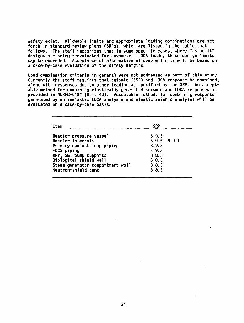
safety exist. Allowable limits and appropriate loading combinations are setforth in standard review plans (SRPs), which are listed in the table thatfollows. The staff recognizes that in some specific cases, where "as built"designs are being reevaluated for asymmetric LOCA loads, these design limitsmay be exceeded. Acceptance of alternative allowable limits will be based ona case-by-case evaluation of the safety margins.
Load combination criteria in general were not addressed as part of this study.Currently the staff requires that seismic (SSE) and LOCA response be combined,along with responses due to other loading as specified by the SRP. An accept-able method for combining elastically generated seismic and LOCA responses isprovided in NUREG-0484 (Ref. 40). Acceptable methods for combining responsegenerated by an inelastic LOCA analysis and elastic seismic analyses will beevaluated on a case-by-case basis.
Item SRP
Reactor pressure vesselReactor internalsPrimary coolant loop pipingECCS pipingRPV, SG, pump supportsBiological shield wallSteam-generator compartment wallNeutron-shield tank
3.9.33.9.5, 3.9.13.9.33.9.33.8.33.8.33.8.33.8.3
34

5 FUEL-ASSEMBLY EVALUATION
Although core components are included in the structural analysis of the primarysystem, a more-detailed structural analysis of the reactor fuel assembly isperformed to show that the fuel is maintained in a cool condition and thatinsertion of control rods is not prevented. These are basic requirements thatfollow from the General Design Criteria (10 CFR Part 50) and are describedexplicitly in Section 4.2 of the Standard Review Plan (SRP).
To perform the detailed analysis for fuel-assembly structural response, inputinformation is obtained from results of the structural analysis of the primarysystem. The input information includes primary-system motions (for example,core plate, core shroud, and fuel-alignment plate) and transient pressuredifferences as described earlier. Since the basic requirements for fuelintegrity and the input motions are similar to those for the seismic analysis,and since the fuel analysis is done separately from the primary-system analy-sis, unified guidelines for the fuel structural analysis have been developed.These guidelines are described in a proposed Appendix A to SRP Section 4.2.The SRP Appendix is included as Appendix E of this report and has been issuedfor public comment (Federal Register, Vol. 45, No. 40, 2/27/80, p. 12939).
Appendix A of SRP Section 4.2 addresses seismic loads of fuel assembly andstructural loads of LOCAs as well as offering an acceptable method for combin-ing these responses for PWRs and BWRs. It thus includes, but goes beyond,requirements related to asymmetric blowdown loads of Task A-2. The SRPAppendix details analytical methods for predicting structural loads on fuelassembly components (for example, spacer grids, fuel rods, and guide tubes),determination of component strengths, and acceptance criteria for comparingpredicted loads with component strengths. The main points of the acceptancecriteria are summarized below; see Appendix E for details.
(1) Fuel rod (poison rod, control rod, guide tube, etc.) fragmentation doesnot occur. Allowable material strength values used in design shouldbound a large percentage (about 95%) of the distribution of strengthvalues.
(2) LOCA temperature and oxidation limits of Title 10 of CFR 50.46 for thefuel-rod cladding are not exceeded. If the fuel-assembly grid-crushingstrength Pcrit (the force required to permanently deform the grid) is not
exceeded, the standard LOCA analysis is performed; otherwise the effectsof a deformed grid are accounted for in the LOCA analysis. The allowablevalue of Pcrit is a mean of the distribution of measured Pcrit values.
(3) Seismic and LOCA loads are combined by taking the square root of the sumof the squares (SRSS).
Technical background for the SRP Appendix is given in three reports referencedin that appendix.
35

REFERENCES
1. Letter from Operating Reactor Branch Chiefs to all Operating PWR Facili-ties Subject: Survey of Operating Plants to see if they had includedAsymmetric Loads, dated October 15, 1975.
2. Letter from Operating Reactor Branch Chiefs to all Operating PWR Licensees,Subject: Request to evaluate adequacy of reactor system components attheir facilities with respect to Newly identified loads, dated June 1976.
3. Westinghouse Electric Corporation, "Augmented Inservice Inspection ofPiping Welds at the Reactor Vessel Nozzles," WCAP-8802, August 1976.
4. Science Applications Inc., "An Analysis of the Relative Probability ofPipe Rupture at Various Locations in the Primary Cooling Loop of a Pres-surized Water Reactor Including the Effects of a Periodic Inspection,"SAI 001-PA, June 1976.
5. Science Applications, Inc., "An Analysis of the Probability of PipeRupture at Various Locations in the Primary Cooling Loop of a Babcock andWilcox 177 Fuel Assembly Pressurized Water Reactor Including the Effectsof a Periodic Inspection," SAI-050-77-PA, September 1977.
6. Westinghouse Electric Corporation, "Multiflex--A Fortran-IV ComputerProgram for Analyzing Thermal-Hydraulic-Structure System Dynamics,"WCAP-8708(P), WCAP-8709(NP), September 1977.
7. Babcock and Wilcox, "Analytical Methods Description--Reactor CoolantSystem Hydrodynamic Loadings During a Loss of Coolant Accident,"BAW-1032P, May 1979.
8. Combustion Engineering, "Blowdown Analysis Method--Method for Analysis ofBlowdown Induced Forces in a Reactor Vessel," CENPD-252-P, August 1978.
9. J. K. Dienes, C. W. Hint, and L. R. Stein, Los Alamos Scientific Labora-tory, "Computer Simulation of the Hydroelastic Response of a PressurizedWater Reactor to a Sudden Depressurization," LA-NUREG-6772-MS, April 1977.
10. V. L. Streeter and E. B. Wylie, "Two- and Three-Dimensional FluidTransients," ASME Journal of Basic Engineering 90, 501-510, December1968.
11. S. Fabic, "Two- and Three-Dimensional Fluid Transients," Transactions ofthe ANS 14, 360-361, 1971.
10. R. K. Cole, Sandia Laboratories, "An Analysis of the Method of Streeterand Wylie for Multi-dimensional Wave Propagation," SAND 77-0549,July 1977.
36

13. S. Fabic, Kaiser Engineering, "Computer Program WHAM for Calculations ofPressure, Velocity and Force Transients in Liquid Filled Piping Networks,"Report No. 67-49-R, November 1967.
14. Memorandum from E. D. Throm, NRC, to Z. R. Rosztoczy, NRC, "Availabilityof the WHAM/MOD-007 Subcooled Blowdown Hydraulic Analysis Code," May 13,1976.
15. D. Berman et al., Sandia Laboratories, "LOCA Analyses Quarterly Repo4t-April-June 1977," SAND 77-1530, December 1977, pp. 14-6D.
16. S. L. Thompson, Sandia Laboratories, "CSQ--A Two-Dimensional HydrodynamicProgram With Energy and Material Strength," SAND 74-0122, August 1975.
17. R. T. Allemann et al., Battelle Pacific Northwest Laboratories, "AECResearch and Development Report: Coolant Blowdown Studies of a ReactorSimulator Vessel Containing a Simulated Reactor Core," BNWL-1524,June 1971.
18. D. D. Christensen, EG&G Idaho, Inc., "United States Standard Problem 5,Final Report," PG-R-77-44, December 1977.
19. H. M. Delaney, EG&G Idaho, Inc., "United States Standard Problem 6 andInternational Standard Problem 4, Final Report," CVAP-TR-4-78, March 1978.
20. G. F. Brockett et al., EG&G Idaho, Inc., Experimental Investigations ofReactor System Blowdown," IN-1348, September 1970.
21. H. C. Robinson, EG&G Idaho, Inc., "Experiment Data Report for LOFTNonnuclear Test L1-2," TREE-NUREG-1026, January 1977.
22. R. J. Fritz and E. Kiss, General Electric Company, "The Vibration Responseof a Cantilevered Cylinder Surrounded by an Annular Fluid," KAPL-M-6539(RJF-1O), February 24, 1966.
23. D. A. Prelewicz, Westinghouse Electric Corporation, "Hydraulic PressurePulses With Structural Flexibility Test and Analysis," WAPD-TM-1227,April 1976.
24. R. Krieg, E. G. Schlechtendall, and K. H. School, "Design of HDR Experi-mental Program on Blowdown Loading and Dynamic Response of PWR VesselInternals," Nuclear Engineering and Design 43, 1977.
25. Los Alamos Scientific Laboratory "COMPARE MOD-l A Code for the TransientAnalysis of Volumes With Heat Sinks, Flowing Vents and Doors," ReportLA-7199-MS, March 1978.
26. Aerojet Nuclear Company, "Containment Supplement to: RELAP 4 A Computerprogram for Transient Thermal-Hydraulic Analysis," Interim Report1-214-75-03, June 1975.
37
27. Los Alamos Scientific Laboratory "Subcompartment Analysis Procedures,"Report LA-8169-MS, December 1979.
28. I. E. Idel'chik, Handbook of Hydraulic Resistance. Coefficients of LocalResistance and Friction, U.S. Atomic Energy Commission Report AEC-TR-6630,1966.
29. Westinghouse Electric Corporation, "Westinghouse Mass and Energy ReleaseData for Containment Design," WCAP-8312A, August 1975.
30. U.S. Nuclear Regulatory Commission, "Safety Evaluation Report Related tothe Preliminary Design of the BSAR-205 Standard Design by Babcock andWilcox," USNRC Report NUREG-0433, May 1978.*
31. U.S. Nuclear Regulatory Commission, "Safety Evaluation Report for thePreliminary Design Standard, Approval of the Combustion EngineeringStandard Safety Analysis Report--CESSAR System 80," USNRC Report NUREG75/112, December 1975.*
32. C. G. Bruch, ed., Idaho National Engineering Laboratory "RELAP4/MOD5: AComputer Program for Transient Thermal-Hydraulic Analysis of NuclearReactors and Related Systems, User's Manual." Supplement 1,ANSR-NUREG-1335, September 1976.
33. R. E. Mathews, EG&G Idaho, Inc., "Pressurized Water Reactor MechanicalResponse Analysis North Anna Unit 1," RE-E-76-083, December 1976.
34. R. W. Macek, EG&G Idaho, Inc., "Nonlinear LOCA Dynamic Analysis of theIndian Point Unit 3 Primary Coolant System," RE-A-77-106, May 1978.
35. R. F. Lippert, EG&G Idaho, Inc., "LOCA Mechanical Response Analysis ofSan Onofre Unit 2 Pressurized Water Reactor," RE-A-78-252, October 1978.
36. R. W. Macek, EG&G Idaho, Inc., Nonlinear LOCA Dynamic Analysis of the St.Lucie Unit 1 Primary Coolant. System," RE-A-79-024, February 1979.
37. G. L. Thinnes, EG&G Idaho, Inc., Pressurized Water Reactor MechanicalResponse Analysis Erie Unit 1," EA-5119, March 1980.
38. T. R. Thompson, EG&G Idaho, Inc., "Nonlinear LOCA Dynamic Analysis of theArkansas Nuclear One Unit 1 Primary Coolant System," RE-A-78-264, Rev. 1,July 1979.
39. Westinghouse Electric Corporation, "Analysis of Reactor Coolant Systemfor Postulated Loss of Coolant Accident-Indian Point Unit 3 Nuclear PowerPlant," WCAP-9117, June 1977.
40. R. Cudlin, S. Hosford, R. Mattu, and K. Wichman, "Methodology for Combin-ing Dynamic Responses," USNRC Report NUREG-0484, September 1978.*
*Available for purchase from the National Technical Information Service,Springfield, VA 22161.
38

APPENDICES
39


APPENDIX A
TASK ACTION PLAN A-2
ASYMMETRIC BLOWDOWN LOADS ON REACTOR PRIMARY COOLANT SYSTEM
Lead NRR Organization: Division of Operating Reactors(DOR)
Lead Supervisor: Darrell G. Eisenhut,Acting Director, DOR
Task Manager: Steve B. Hosford, EB/DOR
Applicability: Light-Water Reactors (PWRs)
PWR Project Completion Date: October 1979
A-1

1. DESCRIPTION OF PROBLEM
On May 7, 1975, the NRC was informed by Virginia Electric & Power Companythat an asymmetric loading on the reactor vessel supports resulting froma postulated reactor coolant pipe rupture at a specific location (e.g.,the vessel nozzle) had not been considered by Westinghouse or Stone andWebster in the original design of the reactor vessel support system forNorth Anna, Units 1 and 2. In the event of a postulated LOCA at thevessel nozzle, asymmetric LOCA loading could result from forces inducedon the reactor internals by transient differential pressures across thecore barrel and by forces on the vessel due to transient differentialpressures in the reactor cavity. With the advent of more sophisticatedcomputer codes and the accompanying more detailed analytical models, itbecame apparent to Westinghouse that such differential pressures, althoughof short duration, could place a significant load on the reactor vesselsupports, thereby affecting their integrity. Although first identifiedat the North Anna facility, this concern has generic implications for allPWRs.
Upon postulation of a break in a reactor coolant pipe, at the abovementioned locations, several rapidly occurring events could cause internaland external transient loads to act upon the reactor vessel. For thereactor vessel pipe break at the inlet nozzle, asymmetric pressure changestake place in the annulus between the core barrel and the vessel.Decompression could occur on the side of the vessel annulus nearest thepipe break before pressure on the opposite side changes. The momentarymomentary difference in pressure across the core barrel could inducelateral loads in opposite directions on the core barrel and the reactorvessel. Vertical loads could also be applied to the core internals andto the vessel due to the vertical flow resistance through the core andasymmetric axial decompression of the vessel. Simultaneously, as fluidescapes through the break, the annulus between the reactor vessel andbiological shield wall could become asymmetrically pressurized resultingin a difference in pressure across the vessel causing additional horizontaland vertical external loads on the vessel. In addition, the vessel couldbe loaded by the effects of initial tension release and blowdown thrustat the pipe break. The loads occur simultaneously. For a reactor vesseloutlet break the same type of loadings could occur, but the internalloads would be predominantly vertical due to more rapid decompression ofthe upper plenum.
For each of the above-mentioned postulated breaks, the time history ofthe reactor vessel support reactions due to the complete set of simul-taneous horizontal and vertical loads should be calculated.
In the event that such loadings would result in a significant degree offailure within the reactor pressure vessel support system and consequentvessel movement, there is a potential that this could (1) result indamage to the ECCS lines, (2) affect the capability of the control rodsto function properly, and (3) result in damage to other reactor coolant
A-3
system components (pump and steam generator supports). In addition, thedifferential pressures occurring during subcooled blowdown could resultin stresses on fuel assemblies caused by lateral core barrel and coreplate motion. This could degrade heat transfer capability if fuel spacergrids are deformed by impacting either each other or the core baffle.(This loading can occur independently of vessel support failure.)
The above-described phenomena may also exist to some degree in BWR plantsbut is expected to have a lesser safety significance due to the loweroperating pressures. Currently, a plan of resolution for the BWR plantsis being developed by DOR:EB and will be considered as a separate issueoutside the scope of this TAP.
2. PLAN FOR PROBLEM RESOLUTION
A. Background
Foilowing disclosure of this problem during the OL review of NorthAnna Units 1 and 2, a survey of all operating PWR reactors wasconducted in October 1975. That survey showed that neither of theabove described transient differential pressures had been consideredin the design of the reactor vessel supports for any operating PWRfacility.
In June 1976, the NRC requested all operating PWR licensees toproceed to assess the adequacy of the reactor vessel supports attheir facilities with respect to these newly-identified loads. Mostlicensees having a common NSSS vendor took identical or similarpositions with respect to this request and did not respond asrequested.
Most licensees with Westinghouse plants proposed an augmented inserviceinspection program (ISI) of the reactor vessel safe-end-to-end pipewelds in lieu of providing the detailed analysis we requested.Licensees with Combustion Engineering plants submitted a probabilitystudy (prepared by Science Applications, Inc.) in support of aconclusion that a break at this location has such a low probabilityof occurrence that no further analysis is necessary. B&W licenseeshave engaged Science Applications, Inc. for a similar study.
When the W and CE owners group reports were received in September1976, DOR formed a review Task Group consisting of members from DOR,DSS and EDO to evaluate these alternate proposals. In addition,EG&G Idaho, Inc. was contracted to perform an independent review ofthe submitted probability study. A short review schedule wasestablished since it appeared that most licensees would hold off onfurther analysis pending our consideration of their submittals.
Our review of the proposed alternates has been completed. The TaskGroup and EG&G independently reached the same conclusion: that thealternate proposals set forth in these reports should not be accepted
A-4

in lieu of the requested analyses. The basis is that a sufficientdata base does not exist within the nuclear industry to providesatisfactory answers to many information needs we identified. Thisinformation would be needed to support this "no-break" approach.Further investigation of pipe break probabilities is planned by thestaff, see item (3) below.
B. Plan
(1) Letters will be sent to all licensees and applicants statingthat an analysis must be undertaken to assess the design adequacyof the reactor vessel supports and other structures to withstandthe loads when asymmetric LOCA forces are taken into account.*We will point out that it may be possible to group plants suchthat only a limited number of plants need be analyzed, and thatit may be possible to provide a simple "fix" (e.g., piperestraints) which will permit bounding the problem. Therefore,the letters will request licensees and applicants to submittheir schedule for completion of the task.
(2) The staff will meet with the licensees constituting both the Wand the CE owners group to explain why the probability studyreports could not be accepted. We will also provide them allthe questions that have been generated to date as a result ofour review of the W and CE topical reports. (We will not issueformal requests for additional information on these topicals tothese groups of licensees.)
(3) We will review and approve vendor models and codes prior toplant-specific application to the extent possible. The staffor its consultants will audit the calculations on a plant-specific basis where a pre-approved code is not used (thecase-specific reviews are not part of this TAP).
(4) The staff will develop explicit guidelines and acceptancecriteria for the asymmetric LOCA load analysis, including loadcombinations and acceptable alternatives where, depending onthe construction or operating status of a given plant, appli-cation of the guidelines per se could require modificationsthat are judged to be a practical impossibility. Such alter-native guidelines would be designed to provide an adequate andacceptable LOCA load generic issue consistent with safe plantshutdown requirements.
(5) The staff will conduct a pipe break probability study that willencompass (a) advances that are being made in nondestructive
Including an assessment of asymmetric loads produced by large pipe breaksoutside the reactor vessel cavity.
A-5
examination techniques, (b) an improved flaw distribution database of actual NSSS materials, and (c) development of a realisticbreak opening model to describe pipe break characteristics.The pipe break probability study will be used to confirm theadequacy of staff decisions related to the conLinued operationof plants for the interim period until an analysis of theseloads is conducted.
(6) The staff will perform a series of sensitivity studies toindependently evaluate the effect of noding upon the magnitudeand distribution of pressures within typical reactor cavitydesigns. Results of sensitivity studies will be utilized toprepare guidelines for the evaluation of the volumes within theconfines of the reactor cavity.
3. BASIS FOR CONTINUED PLANT OPERATION AND LICENSING PENDING COMPLETION OFTASK
The safety issue addressed by this Task Action Plan (TAP) is primarilyapplicable to pressurized light water reactors (PWRs). As discussed inSection 1, the potential asymmetric loading conditions for boiling waterreactors (BWRs) appear to be of a lesser safety significance. Thepotential loads are not expected to be as large, since the reactor vesselpressure and sub-cooling are substantially lower than for PWR plants(i.e., 1000 psia and approximately 40 Btu/lb, respectively for BWRscompared to 2200 psia and 100 Btu/lb for PWR plants).
With respect to PWRs, each NSSS vendor (i.e., Westinghouse, Babcock andWilcox, and Combustion Engineering) has submitted topical reports whichdescribe analysis methods for assessing the internal asymmetric blowdownloads. In accordance with the schedule for completion of this TAP, staffreview and approval of these topical reports will be completed by December1978 (the Westinghouse analysis methods have already been approved by thestaff).
Topical reports have not been submitted by all the vendors and architectengineers that deal with asymmetric cavity and reactor vessel externalloads in PWRs. These reviews are conducted by the staff on a case bycase basis. Technical assistance programs are underway to resolve thoseaspects related to the reactor vessel cavity asymmetric loads and structuralresponse methods and criteria. It is expected that these programs willbe completed in FY 79 and will provide acceptable methods and models forindependent staff analysis. Current staff evaluations include case-by-casereviews of applicants' mass and energy blowdown calculations, reactorcavity loads including pressurization and vessel internal loads, and theresulting structural response. The results and conclusions drawn fromthese ongoing staff activities are subject to confirmation in the courseof development of the generic methods and models that will be the outputof this generic task.
A-6
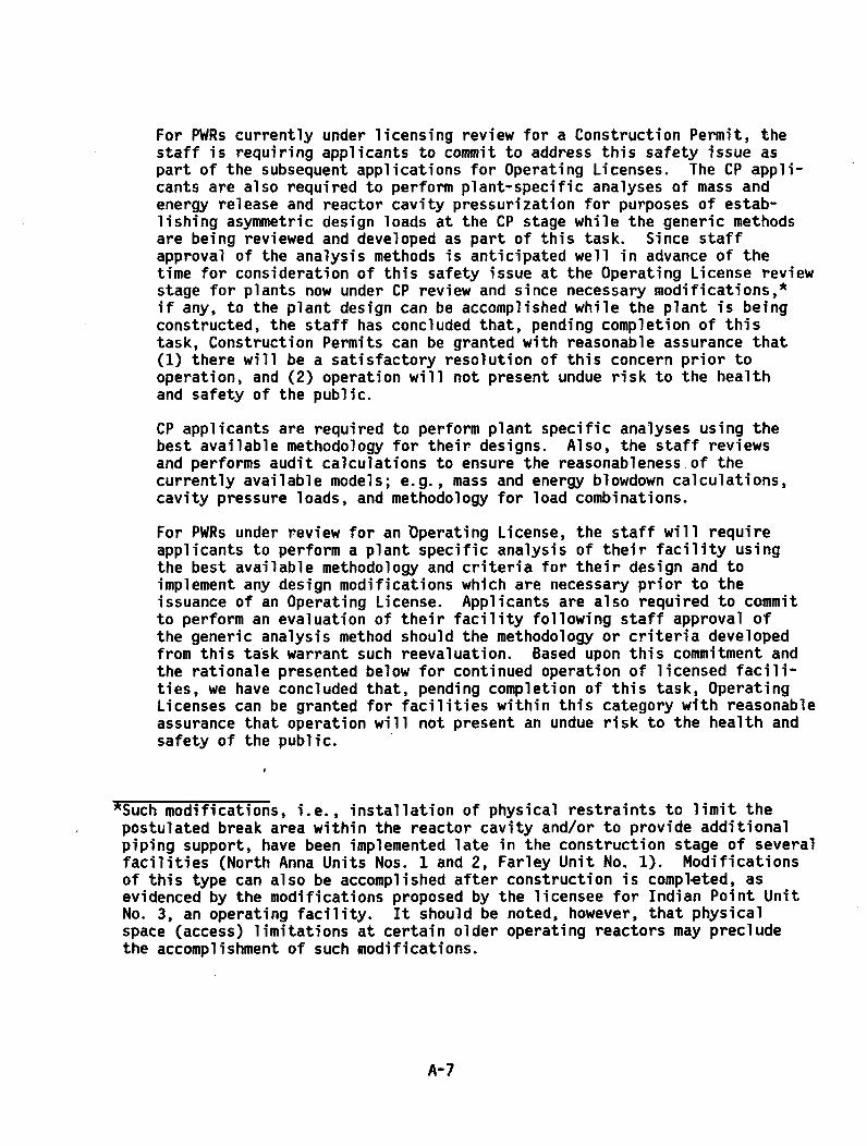
For PWRs currently under licensing review for a Construction Permit, thestaff is requiring applicants to commit to address this safety issue aspart of the subsequent applications for Operating Licenses. The CP appli-cants are also required to perform plant-specific analyses of mass andenergy release and reactor cavity pressurization for purposes of estab-lishing asymmetric design loads at the CP stage while the generic methodsare being reviewed and developed as part of this task. Since staffapproval of the analysis methods is anticipated well in advance of thetime for consideration of this safety issue at the Operating License reviewstage for plants now under CP review and since necessary modifications,*if any, to the plant design can be accomplished while the plant is beingconstructed, the staff has concluded that, pending completion of thistask, Construction Permits can be granted with reasonable assurance that(1) there will be a satisfactory resolution of this concern prior tooperation, and (2) operation will not present undue risk to the healthand safety of the public.
CP applicants are required to perform plant specific analyses using thebest available methodology for their designs. Also, the staff reviewsand performs audit calculations to ensure the reasonableness of thecurrently available models; e.g., mass and energy blowdown calculations,cavity pressure loads, and methodology for load combinations,
For PWRs under review for an Operating License, the staff will requireapplicants to perform a plant specific analysis of their facility usingthe best available methodology and criteria for their design and toimplement any design modifications which are necessary prior to theissuance of an Operating License. Applicants are also required to committo perform an evaluation of their facility following staff approval ofthe generic analysis method should the methodology or criteria developedfrom this task warrant such reevaluation. Based upon this commitment andthe rationale presented below for continued operation of licensed facili-ties, we have concluded that, pending completion of this task, OperatingLicenses can be granted for facilities within this category with reasonableassurance that operation will not present an undue risk to the health andsafety of the public.
*Such modifications, i.e., installation of physical restraints to limit thepostulated break area within the reactor cavity and/or to provide additionalpiping support, have been implemented late in the construction stage of severalfacilities (North Anna Units Nos. 1 and 2, Farley Unit No. 1). Modificationsof this type can also be accomplished after construction is completed, asevidenced by the modifications proposed by the licensee for Indian Point UnitNo. 3, an operating facility. It should be noted, however, that physicalspace (access) limitations at certain older operating reactors may precludethe accomplishment of such modifications.
A-7

For PWRs currently licensed for operation, we have concluded that thereis reasonable assurance that continued operation, pending completion ofthis task, does not constitute an undue risk to the health and safety ofthe public for the following reasons.
As discussed below, the likelihood of occurrence of an initiating eventof sufficient magnitude to seriously challenge the structural adequacy ofthe vessel support members or other structures is low.
The disruptivegailure of a reactor vessel itself has been estimated tolie between 10 and 10 per reactor year -- so low that it is notconsidered as a design basis event. The rupture probability of pipes isestimated to be higher. The data base used by WASH-1400 indicates amedian value of 10 - for LOCA initiating ruptures per plant-year for al•pipe sizes 6" and greater (with a lower and upper bound of 10 and 10respectively). We believe that considering the large size of the pipt inquestion4 (up to 50" O.D. and 4-1/8" thick), a median value nearer 10than 10 is more appropriate using the same data base. In addition, thequality control of the piping used in nuclear power plants is somewhatbetter than that of the piping used in the WASH-1400 data base.
Because (1) the break of primary concern must be large (and therefore oflow probability); (2) only certain break locations lead to high loads;and (3) these welds are currently subject to preservice and inserviceinspection by volumetric and surface techniques in accordance with ASMECode Section XI, we conclude that the probability of a pipe break resultingin substantial transient loads on the vessel support system or otherstructures is acceptably small and that reactor operation and licensingof facilities for operation can continue during the interim period ofapproximately 2 years while this matter is being resolved.
It is anticipated that the plant-unique analyses, which Will be performedfollowing staff approval of the generic analysis methods, will indicatethat design modifications may be necessary to restore the originallyintended safety margins at certain operating facilities. Such modifi-cations, i.e., installation of physical restraints to limit the postulatedbreak area within the reactor cavity, have already been shown to befeasible. In the event that design modifications are judged to beimpossible for specific operating facilities, alternative solutions,including such things as augmented inservice inspection, will be requiredto ensure adequate safety margins.
4. NRR TECHNICAL ORGANIZATIONS INVOLVED
A. Analysis Branch, Division of Systems Safety. Has lead responsibilityfor review of vendor hydrodynamic analysis methods and codes.
Manpower Estimates: 0.5 man-months in FY 1979
B. Core Performance Branch, Division of Systems Safety. Has leadresponsibility for reviewing vendor analysis methods for calculatingloads on fuel assemblies resulting from decompression for plantsunder CP and OL review.
A-8

Manpower Estimates: 1.75 man-months in FY 1979
C. Containment Systems Branch, Division of Systems Safety. Responsiblefor reviewing vendor models and methods for calculating asymmetriccavity loads for all plants, and associated vendor models.
Manpower Estimates: 4.6 man-months in FY 1979
D. Mechanical Engineering Branch, Division of Systems Safety. Responsiblefor review of structural aspects of vendor analysis methods andcodes for plants not licensed for operation. Responsible fordeveloping structural acceptance criteria (with Engineering Branch,DOR).
Manpower Estimates: 1.5 man-months in FY 1979
E. Engineering Branch, Division of Operating Reactors. Responsible forreview of structural aspects of analysis methods and codes applica-ble to operating reactors (including loads on fuel assemblies).Responsible for development of structural acceptance criteria (withMechanical Engineering Branch, DSS).
Manpower Estimates: 1.0 man-months in FY 1979
F. Engineering Branch, Division of Operating Reactors. Responsible forthe coordination and management of this Technical Activity.
Manpower Estimates: 1.5 man-months in FY 1979
5. TECHNICAL ASSISTANCE
A. Managed by DOR (Engineering Branch):
Contractor: EG&G Idaho, Inc.
Funds Available: $70K in FY 1979.
This is an NRC program to independently model representative Westing-house 4-loop (Indian Point 3), B&W (Arkansas Nuclear One Unit 1),and CE (St. Lucie 1) plants for the purpose of assessing the loadson all major structures and components resulting from asymmetricLOCA loads. The purpose of this program is to develop an independentNRC capability for performing inelastic dynamic analyses. Sensitivitystudies will be performed to evaluate the effects of various breakopening times, effects of component stiffness, and three-dimensionalcoupling effects.
B. Managed by DSS (Mechanical Engineering Branch):
Contractor: EG&G Idaho, Inc.
Funds Available: 80K in FY 1979
A-9

This is an NRC/DSS program to provide the staff with the analyticaltools necessary to independently verify the selection of designbasis pipe rupture locations; and to verify that the criteria forassurance of integrity under LOCA & SSE loads for reactor coolantpiping, the reactor vessel, steam generators, main coolant pumps andthe supports for these components have been implemented correctly.Verification analyses for a B&W plant (Erie), and a BWR plant(Zimmer 1) will be run to verify results reported by the applicants.Support models will be designed to be revised as necessary torepresent various support configurations utilized by Architect/Engineers of the plants under CP/OL review.
C. Managed by DSS (Core Performance Branch)
Contractor: EG&G, Inc.
Funds Available: 60K in FY 1979
This is an NRC/DSS program to perform independent calculations offuel assembly response from LOCA as well as seismic loads. Auditcalculations are performed to assist NRC in reviewing vendoranalytical methods. Evaluation on Westinghouse and GeneralElectric Co. analytical methods for fuel assembly response have beencompleted.
In addition, the contractor will assist DSS/CPB in developingacceptance criteria for the fuel assembly evaluation.
6. INTERACTIONS WITH OUTSIDE ORGANIZATIONS
A. W Owners Group of licensees
The W owners group of licensees is an ad hoc organization of most(but7not all) owners of operating W pliants, formed for the purposeof sponsoring and proposing the augmented inservice inspectionprogram (WCAP-8802) in lieu of furnishing the detailed analysisrequested by NRC. This group of licensees has engaged WestinghouseElectric Corporation as its principal consultant.
With the advent of the NRC decision to request all licensees for adetailed analysis and to set aside - at least for the present--theISI proposal, the continued role of this licensee group is undetermined.
B. CE Owners Group of Licensees
The CE owners group of licensees is also an ad hoc organization ofmost owners of operating CE plants. This group sponsored the probabi-lity study prepared by Science Applications, Inc., which concludedthat the probability of severe pipe breaks that could trigger theloads under consideration is below the threshold of concern. Thefuture role of this licensee group is also undetermined.
A- 10
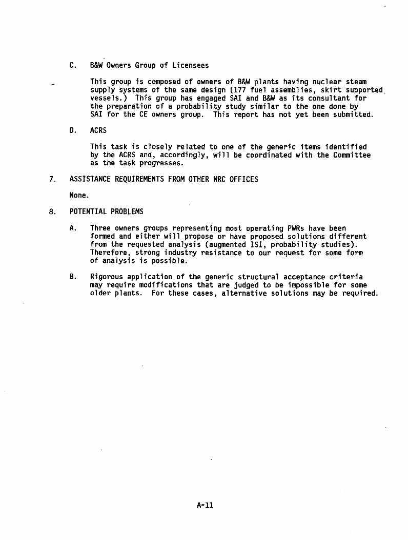
C. B&W Owners Group of Licensees
This group is composed of owners of B&W plants having nuclear steamsupply systems of the same design (177 fuel assemblies, skirt supportedvessels.) This group has engaged SAI and B&W as its consultant forthe preparation of a probability study similar to the one done bySAI for the CE owners group. This report has not yet been submitted.
D. ACRS
This task is closely related to one of the generic items identifiedby the ACRS and, accordingly, will be coordinated with the Committeeas the task progresses.
7. ASSISTANCE REQUIREMENTS FROM OTHER NRC OFFICES
None.
8. POTENTIAL PROBLEMS
A. Three owners groups representing most operating PWRs have beenformed and either will propose or have proposed solutions differentfrom the requested analysis (augmented ISI, probability studies).Therefore, strong industry resistance to our request for some formof analysis is possible.
B. Rigorous application of the generic structural acceptance criteriamay require modifications that are judged to be impossible for someolder plants. For these cases, alternative solutions may be required.
A-I1

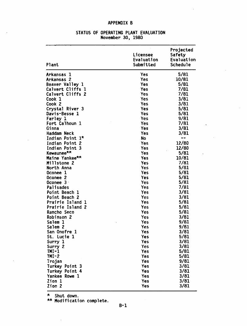
APPENDIX B
STATUS OF OPERATING PLANT EVALUATIONNovember 30, 1980
ProjectedLicensee SafetyEvaluation Evaluation
Plant Submitted Schedule
Arkansas 1 Yes 5/81Arkansas 2 Yes 10/81Beaver Valley 1 Yes 5/81Calvert Cliffs 1 Yes 7/81Calvert Cliffs 2 Yes 7/81Cook 1 Yes 3/81Cook 2 Yes 3/81Crystal River 3 Yes 5/81Davis-Besse 1 Yes 5/81Farley 1 Yes 9/81Fort Calhoun 1 Yes 7/81Ginna Yes 3/81Haddam Neck Yes 3/81Indian Point 1* No --
Indian Point 2 Yes 12/80Indian Point 3 Yes 12/80Kewaunee** Yes 5/81Maine Yankee** Yes 10/81Millstone 2 Yes 7/81North Anna Yes 5/81Oconee 1 Yes 5/81Oconee 2 Yes 5/81Oconee 3 Yes 5/81Palisades Yes 7/81Point Beach 1 Yes 3/81Point Beach 2 Yes 3/81Prairie Island 1 Yes 5/81Prairie Island 2 Yes 5/81Rancho Seco Yes 5/81Robinson 2 Yes 3/81Salem 1 Yes 9/81Salem 2 Yes 9/81San Onofre 1 Yes 3/81St. Lucie 1 Yes 5/81Surry 1 Yes 3/81Surry 2 Yes 3/81TMI-1 Yes 5/81TMI-2 Yes 5/81Trojan Yes 9/81Turkey Point 3 Yes 3/81Turkey Point 4 Yes 3/81Yankee Rowe 1 Yes 3/81Zion 1 Yes 3/81Zion 2 Yes 3/81
* Shut down.
** Modification complete.B-1


APPENDIX C
CHARACTERISTICS OF PIPE BREAKS
The staff performed a study at EG&G to investigate pipe-break area and timecharacteristics. Pipe-break flow area and the time associated with developmentof flow area are major considerations in the development of asymmetric LOCAloads. Historically, the staff has required conservative assumptions in theseareas to be used in the development of loading transients. A task in thegeneric action plan A-2 required the staff to investigate realistic characteris-tics of pipe breaks.
The study performed by EG&G included a review of pipe-break models submittedby each PWR NSSS vendor and the development of pipe-break characteristics atfour specific plants. A summary of the EG&G report* and its conclusions document-ing that study are presented below.
This report documents an analysis performed by EG&G Idaho on break-openingtimes and associated flow areas due to pipe separation during a postulatedloss-of-coolant accident (LOCA). This effort supports the resolution of theU.S. Nuclear Regulatory Commission (NRC) Category A Task Action Plan A-2 onasymmetric LOCA loads and provides NRC Division of Operating Reactors (DOR)the capability of independently verifying vendor analyses.
A postulated LOCA for a nuclear-power plant is initiated by a severance,or break, in the piping of the primary coolant system, inducing severetransient loads on piping, major components, and supports in the system.
The severity of the depressurization transient is directly dependent uponthe combination of break size and length of time required for pipe separation.In general, LOCA thermal hydraulic analyses have taken the conservativeapproach by assuming break openings to occur instantaneously (that is,10 msec or less). If it can be shown that this approach is unrealistic,(that is, break openings are not instantaneous), the loads associated withthe LOCA transients may be greatly reduced.
In this report, break-opening times and areas are examined on a plant-specific basis. The analysis covers four nuclear-power plants designedby three'different vendors: San Onofre Unit 2 and St. Lucie Unit 1designed by Combustion Engineering (CE), Arkansas Nuclear One Unit 1designed by Babcock and Wilcox (B&W), and Indian Point Unit 3 designed byWestinghouse. These four plants were chosen for two reasons: (1) mechanicaldynamic response analyses of all four plants have previously been performedfor postulated LOCA applied loads by EG&G Idaho in support of NRC licensingaudits, and (2) the four plants represent a good cross-section of nuclear-plant design. Information from the previous analyses was utilized in
*R. F. Lippert, EG&G Idaho, Inc., "Study of Break Opening Area/Time Determinationfor Postulated LOCA Guillotine Pipe Ruptures of Nuclear Primary Coolant Systems,"RE-A-79-093, July 1979.
C-i
expediting development of models of the necessary segments of the primarycoolant loops and in providing appropriate hydraulic transients. Thestructural models include material and geometric nonlinearities whenapplicable.
Subsequent sections of the report include: (1) an investigation ofvarious techniques for geometrically calculating break-opening areas, (2)a description of the several analytical structural models employed in theanalysis, (3) a description of the applied LOCA loadings associated withthe various postulated pipe breaks analyzed, and (4) a presentation ofthe resulting pipe-break areas as a function of time and associatedobservations. In addition, the appendices include vendor break-areaprocedures, plant geometries, and plots of break-area time-history results.
The EG&G analysis of four nuclear plants to study break opening areas andtimes for postulated LOCA pipe ruptures presented in this report provides thefollowing observations. Times for break-opening areas to develop are signifi-cantly greater than the 1- and 1O-msec times presently assumed, and, in thecases of limited breaks, the break areas developed were significantly lessthan those to which the plants were designed. Both results indicate significantconservatism in the design and analysis approaches generally employed. Forthe results of this study to be applicable to nuclear-power plants other thanthose analyzed herein, careful consideration must be given to the particularplant's size, power, dimensions, and geometry as well as to the type ofstructural analysis and LOCA load development.
C-2

APPENDIX D
LETTERS TO APPLICANTS/LICENSEES
D-1

-0 UNITED STATESNUCLEAR REGULATORY COMMISSION
WASHINGTON, D. C. 20555
All PWR Licensees
Gentlemen:
In October of 1975, the NRC staff notified each licensee of an operatingPWR facility of a potential safety problem concerning the design of thereactor pressure vessel support system. Those letters requested eachlicensee to review the design basis for the reactor vessel support systemfor each of its PWR facilities to determine whether certain transientloads, which were described in the enclosure to the letter, had beenappropriately taken into account in the design. Furthermore, theseletters indicated that, on the basis of the results of licensees' reviews,a reassessment of the reactor vessel support design for each operatingPWR facility may be required.
Licensee responses to that request indicated that these postulatedasymmetric loads have not been considered in the design basis forthe reactor vessel support system, reactor internals including thefuel, steam generator supports, pump supports, emergency core coolingsystem (ECCS) lines, reactor coolant system piping, or control roddrives.
Subsequently in June 1976, the NRC staff informed each PWR licenseethat a reassessment of the reactor vessel support system design foreach of its facilities was required. While the emphasis of theseletters was primarily focused on the need to reassess the vesselsupport design for transient differential pressures in the annularregion between the reactor vessel and the cavity shield wall andacross the core barrel, we indicated that our generic review mayextend to other areas in the nuclear steam supply system (NSSS) andthat further evaluation may be required.
For your information, Enclosure 1 is a summary of the backgroundand current status of our review efforts related to this genericconcern.
D-3

All PWR Licensees -2- January 20, 1978
We have now determined that an assessment of the potential fordamage to other NSSS component supports (e.g., steam generator and -
pump supports), the fuel assemblies, control rod drives, and ECCSpiping attached to the reactor coolant system due to loadingsassociated with postulated coolant system piping breaks is required.Our request for additional information transmitted to you in June 1976has been revised both to clarify our original request and to identifythe extension of our concerns to other areas in the NSSS, asidentified above. A copy of this revised request for additionalinformation is provided as Enclosure 2.
The revised request for additional information identifies a requirementthat your assessment of potential damage to the reactor vessel and otherNSSS component supports, reactor vessel, fuel and internals, attached ECCSlines and the control rod drives should include consideration of breaksboth inside and outside of the reactor pressure vessel cavity. Thisassessment should be made for postulated breaks in the reactor coolantpiping system, (secondary systems are not to be included), including thefollowing locations:
a) Reactor vessel hot and cold lea nozzle safe endsb) Pump discharge nozzlec) Crossover legd) Hot leg at the stean generator (B&W and CE plants only)
A number of licensees, have presented to the NRC staff alternate proposals,other than to conduct a detailed analyses, to resolve this concern. Basedupon our review of these proposals, we have concluded that these alternativeproposals do not establish an acceptable basis for long term operationwithout a detailed assess-nent of the risk resulting from these postulatedtransient loading conditions. We have, however, concluded that the lowprobability for occurrence of an event which could result in these loadsestablishes an adequate basis to justify continued operation for a shortterm period.
The IIRC staff will consider an analysis that is applicable to more thanone specific plant if it can be adequately demonstrated that such ananalysis is either representative or bounding for each plant concerned.
Additional guidance regarding loading combinations (safe shutdown earthquakeloads, loss of coolant accident loads), will be provided by about March 1,1978, following the conclusion of staff investigations in this area.
D-4

All PWR Licensees -3- January 20, 1978
Please respond within 30 days of receipt of this letter, indicating yourintent to proceed with an evaluation of the overall asymmetric loss ofcoolant accident (LOCA) loads as described herein. In addition, pleasesubmit to us, within 90 days, your detailed schedule for providing therequired evaluation. Your schedule should be consistent with our desireto resolve this problem within two years and should clearly state yourintent to demonstrate the safety of lono term continued operation.
We are transmitting information copies of this letter to the Westinghouse,Combustion Engineering and Babcock & Wilcox Companies. If you have anyquestions or want any clarification on this matter, please call your NRCProject Manager.
Sincerely,
Victor Ste DirectorDivision of Operating ReactorsOffice of Nuclear Reactor Regulation
Enclosures:1. Background and Current Status2. Revised Request for Additional
Information
cc w/enclosure:See attached listing
D-5

January 20, 1978
ENCLOSURE 1
BACKGROUND AND CURRENT STATUS OF THE NRC STAFF REVIEWOF ASYMMETRIC LOCA LOADS FOR PWP FACILITIES
On May 7, 1975, the NRC was informed by Virginia Electric & Power Companythat an asymmetric loading on the reactor vessel Supports resulting froma postulated reactor coolant pipe rupture at a specific location (e.g.,the vessel nozzle) had not been considered by Westinghouse or Stone &Webster in the original design of the reactor vessel support system forNorth Anna, Units 1 and 2. It had been identified that in-the event ofa postulated instantaneous, double-ended offset LOCA at the vessel nozzle,asymmetric loading could result from forces induced on the reactor inter-nals by transient differential pressure across the core barrel and byforces on the vessel due to transient differential pressures in the reactorcavity. With the advent of more sophisticated computer codes and theaccompanying mnore detailed analytical models, it became apparent that suchdifferential pressures, although of short duration, could place a signi-ficant load on the reactor vessel supports and on other components, there-by possibly affecting their integrity. Although this potential safetyconcern was first identified during the review of the North Anna facilities,it has generic implications for all PWRs.
Upon closer examination of this situation, it was determined that postu-lated breaks in a reactor coolant pipe at vessel nozzles were not the onlyarea of concern but rather that other pipe breaks in the reactor coolantsystem could cause internal and external transient loads to act upon thereactor vessel and other com1ponents. For the postulated pipe break inthe cold leg, asymmetric pressure changes could take place in the annulusbetween the core barrel and the vessel. Decomnpression could occur on theside of the vessel annulus nearest the pipe break before the pressure onthe opposite side of the vessel changes. This momentary differentialpressure across the core barrel could induce lateral loads both on thecore barrel and on the reactor vessel. Vertical loads could also beapplied to the core internals and to the vessel due to the vertical flowresistance through the core and asymmetric axial decompression of thevessel. Simultaneously, for vessel nozzle breaks, the annulus betweenthe reactor and biological shield wall could become asymmetricallypressurized resulting in a differential pressure across the vesselcausing additional horizontal and vertical external loads on the vessel.In addition, the vessel could be loaded by the effects of initial ten-sion release and blowdown thrust at the pipe break. These loads couldoccur simultaneously. For a reactor vessel outlet break, the same typeof loadings could occur, but the internal loads would be predominantlyvertical due to more rapid decompression of the upper plenum.
D-6

-2-
Although the NRC staff's original emphasis and concern were focusedprimarily on the integrity of the reactor vessel support system withrespect to postulated breaks inside the reactor cavity (i.e., at anozzle), it has since become apparent that significant asymmetric forcescan also be generated by postulated pipe breaks outside the cavityand that the scope of the problem is not limited to the vessel supportsystem itself. For such outside-cavity postulated breaks, theaforementioned concerns, such as the integrity of fuel assemblies andother structures, need to be examined.
In June 1976, the NRC requested all operating PWR licensees to evaluatethe adequacy of the reactor system components and their supports attheir facilities with respect to these newly-identified loads.
In response to our request, most licensees with Westinghouse plantsproposed an augmented inservice inspection program (ISI) of thereactor vessel safe-end-to-end pipe welds in lieu of providing anevaluation of postulated piping failures. Licensees with CombustionEngineering plants submitted a probability study (prepared by ScienceApplications, Inc.) in support of their conclusion that a break at aparticular location (vessel nozzle) has such a low probability ofoccurrence that no further analysis is necessary. A similar study hasbeen recently submitted by Science Applications, Inc. (SAI) for B&Wplants.
When the Westinghouse and CE owners group reports were received inSeptember 1976, the NRC formed a special review task group to evaluatethese alternative proposals. In addition, EG&G Idaho, Inc., wascontracted to perform an independent review of the SAI probabilitystudy submitted for the CE owners group.
This review effort resulted in a substantial number of questionswhich previously have been provided to representatives of each group.Based on the nature of these questions and other factors to bediscussed later in this report, we cannot accept these reports intheir present form as a resolution for the asymmnetric LOCA load genericissue. Based on our review, we have concluded that a sufficient database does not presently exist within the nuclear industry to providesatisfactory answers to these information needs. Several long-termexperimental programs would be required to provide much of thisinformation. Although the probability study recently submitted bySAI for certain B&W owners does respond to some of the informalquestions raised during our review of the SAI report prepared byCE plants, the more fundamental questions remain. Therefore, thisconclusion also applies to the SAI topical report for B&W plants(SAI-050-77-PA).
b-7

-3-
A second - and equally important - reason for not acceptinq probability/ISIapproaches as a solution at this point concerns our need and industry's needto oain a better understandina of the problem. We consider it essentialthat an understandinq of the important breaks and associated conseauencesbe known before applyinq any remedy - be it pipe restraints, Drobability,ISI, or some combination of these measures. Only in this way will we havea basis on which to judge the importance of the remedy with respect towhat it is desianed to prevent.
Although we have many questions on each of these tooical reports, thisdoes not mean that we view the probabilistic/ISI approach as completelywithout merit. In fact, the results of a probabilistic evaluation servesas the basis for continued operation and licensing of nuclear plantsduring this interim period while additional evaluations can be performedby vendors and licensees.
We believe that the justification for continued plant operation has as itsbasic foundation the fact that the event in question, i.e., a hypotheticaldouble-ended instantaneous rupture of the main coolant pipe at a particularlocation, has a very low probability of occurrence.
The disruptive failure probagility of 7a reactor vessel itself has beenestimated to lie between 10 and 10' per reactor year - so low that itis not considered as a design basis event. The rupture probability of4pipes is estimated to be hiqher. WASH-1400 used a median value of 10"4
for LOCA initiating ruptures per plant-year Ior all pipes sizes 6" andqreater (with a lower and upper bound of 1O" and 10- , respectively).We believe that considerino the large size of the pipes in question (upto 50" O.D. and 4-1/8" thick), the lower bound is more appronriate sincethese pipes are more like vessels in size. In addition, the quality con-trol of this pipinq is the best available and somewhat better than thatof the piping used in the WASH-1400 study.
These factors, coupled with the facts that (1) the break of primary con-cern must be very laroe, (2) it must occur at a specific location, (3)the break must occur essentially instantaneously, and (4) these weldsare currently subject to inservice inspection by volumetric and surfacetechniques in accordance with ASME Code Section XI, lead us to concludethat the probability of a pipe break resulting in substantial transientloads on the vessel support system or other structures is acceptablysmall such that continued reactor operation and continued licensinq offacilities for operation can continue while this matter is beinqresolved.
D-8

-4-
In support of the above, the staff has developed a short-term interim cri-terion to determine if an acceptable level of safety exists for operatingPWRs under conditions of a postulated pipe break. This interim criterionis based on a simplified probabilistic model that incorporates elastic frac-ture mechanics techniaues to estimate the probability of a pipe break.Critical flaw size and subcritical flaw qrowth rates were determined assuminathe presence of a surface flaw located in a circumferential weld of athick-walled pipe, Determination of the critical flaw size was based onan estimated fracture toughness value of KIC at a minimum temnerature of200 F and a uniform tensile stress equal to the consideration of variousoperatino conditions producinq elastically calculated stresses ranaina invalue from I to 3 times the material minimum yield strenoth.
Then, using the calculated critical flaw size, the subcritical orowthrate, and an estimated probability distribution of an undetected flaw inthick-walled pipe wilds, the upoer bound probability of pipe break wasestimated to be 10- . This value is also supported by a recent publica-tion by Dr. S. H. Brsh* which states that actual failure statisticsconfirm rates of 10- to l0- per reactor-year in large pipes, withhigher rates as the pipe size decreases. Considerina these analyses,we conclude that our conservative estimate on a pipe break in the primarycoolant system is in the ranae of 10" to 10'. This estimated pipebreak probability is considered acceptably low to justify short-termoperation of nuclear power plants.
In view of all previous discussions concerning this issue, the NRC staffhas concluded that an evaluation mujst be undertaken to assess the designadeouacy of the reactor vessel supports and other affected structures andsystems to withstand asymmetric LOCA loads, includinn an assessment ofthe effects of asymmetric loads produced by various pipe breaks bothinside and outside the reactor cavity. On nerforming these evaluationsthe staff will permit the grouping of plants, where adeouate justifica-tion for such grouping exists, in order to limit the number of plantsto be analyzed. Alternatively, the staff will permit the analyzina ofa "prototypical" plant, which is sufficiently representative of agroup of plants, to provide the necessary information. Both of theseconcepts have been discussed with the Westinghouse and CE Owners Groups,and we believe that such approaches could save a significant amount oftime and effort in obtaining results on which to base any neededcorrective measures. The NRC staff is prepared to meet with PWR licen-sees to discuss such approaches, and has already done so. For example,we met with the Westinahouse owners croup on October 19, 1977 for thepurpose of discussing a generic solution for breaks outside the reactorcavity. It is expected that a similar meeting will be held in the near
*"Critical Factors in Blowdown Loads in the PWR Guillotine NozzleBreak (Volume 2 - the Asymmetric Load Problem)", dated June 6, 1977
D-9
-5-
future to address breaks located inside the cavity. This "phased"approach is acceptable to us, provided that it sheds light on andserves to expedite consideration of the more limiting inside-cavity breaks.
For your information, the NRC has a technical assistance contract withEG&G Idaho, Inc., to independently model representative Westinghouse,B&W, and CE plants for the purpose of assessing the loads on all majorstructures and components resulting from asymmetric LOCA loads. Webelieve that the results of this program which will include sensitivitystudies, will provide significant confirmatory information related tothis generic safety concern.
Although, as stated earlier, we believe that continued operation andlicensing of facilities for the short ter' is justified, we also believethat efforts to resolve this issue should proceed without delay, withthe objective of both completing the necessary assessments and installingany necessary plant modifications within two years. In making this state-ment, we wish to make it clear that plant modifications, if indicated bylicensee assessments, is the preferred approach. At the same time, werecognize that there may be cases wherein appropriate modifications maybe judged to be unwarranted based on the consideration of overall risk.In such cases, and only in such cases, we will be prepared to give furtherconsideration to alternate approaches, such as probability ISI, We feel,however, that ISI techniques as they exist today could be considerablyimproved, and, to the extent that such improvements could have a directbearing on this problem as well as an impact of nuclear safety in general,we would welcome their development.
D-1O
January 20, 1978
ENCLOSURE 2
REVISED REQUEST FOR ADDITIONAL INFORMATION
Recent analyses have shown that certain reactor system components andtheir supports may be subjected to previously underestimated asymmetricloads under the conditions that result from the postulation of rupturesof the reactor coolant piping at various locations. It is thereforenecessary to reassess the capability of these reactor system componentsto assure that the calculated dynamic asymmetric loads resulting fromthese postulated pipe ruptures will be within the bounds necessary toprovide high assurance that the reactor can be brought safely to a coldshutdown condition. For the purpose of this request for additional infor-mation the reactor system components that require reassessment shallinclude:
a. Reactor Pressure Vesselb. Fuel Assemblies, Including Grid Structuresc. Control Rod Drivesd. ECCS Piping that is Attached'to the Primary Coolant Pipinge. Primary Coolant Pipingf. Reactor Vessel, Steam Generator and Pump Supportsg. Reactor Internal.sh. Biological Shield Wall and Neutron Shield Tank (where applicable)i. Steam Generator Compartment Wall
The following information should be included in your reassessment of theeffects of postulated asymmetric LOCA loads on the above-mentioned reactorsystem components and the reactor cavity structure.
1. Provide arrangement drawings of the reactor vessel, the steam generatorand pump support systems to show the geometry of all principal elementsand materials of construction.
2. If a plant-specific analysis will not be submitted for your plant,provide supporting information to demonstrate that the generic plantanalysis under consideration adequately bounds the postulated accidentsat your facility. Include a comparison of the geometric, structural,mechanical and thermal hydraulic similarities between your facilityand the case analyzed. Discuss the effects of any differences.
3. Consider postulated breaks at the reactor vessel hot and cold legnozzle safe ends, pump discharge nozzle and crossover leg that re-sult in the most severe loading conditions for the above-mentioned
D-11
-2-
systems.* Provide an assessment of the effects of asymmetric pres-sure differentials on these systems/components in combination with
.all external loadings including asymmetric cavity pressurization forboth the reactor vessel and steam generator which might result fromthe required postulate. This assessment should consider:
a. limited displacement break areas where applicableb. consideration of fluid-structure interactionc. use of actual time-dependent forcing functiond. reactor support stiffnesse. break opening times.
4. If the results of the assessment required by 3 above indicate loadsleading to inelastic action in these systems or displacement exceedingprevious design limits provide an evaluation of the following:
a. Inelastic behavior (including strain hardening) of the materialused in the system design and the effect on the load transmittedto the backup structures to which these systems are attached.
5. For all analysis performed, include the method of analysis, the struc-tural and hydraulic computer codes employed, drawings of the modelsemployed and comparisons of the calculated to allowable stressesand strains or deflections with a basis for the allowable values.
6. Provide an estimate of the total amount of permanent deforma-tionsustained by the fuel spacer grids. Include a description of theimpact testing that was performed in support of your estimate.Address the effects of operating temperatures, secondary impacts,and irradiated material properties (strength and ductility) on theamount of predicted deformation. Demonstrate that the fuel willremain coolable for all predicted geometries.
7. Demonstrate that active components will perform their safety functionwhen subjected to the postulated loads resulting from a pipe breakin the reactor coolant system.
8. Demonstrate functionability of any essential piping where servicelevel B limits are exceeded.
In order to review the methods employed to compute the asymmetricalpressure differences across the core support barrel during subcooledportion of the blowdown analysis, the following information is requested:
*B&W and CE plant licensees shoild also consider breaks in tne hot legat the steam generator inlet.
D-12

-3-
1. A complete description of the hydraulic code(s) used including thedevelopment of the equations being solved, the assumptions andsimplifications used to solve the equations, the limitations re-sulting from these assumptions and simplifications and the numericalmethods used to solve the final set of equations. Provide comparisonswith experimental data, covering a wide range of scales, to demonstratethe applicability of the code and of the modeling procedures ofthe subcooled blowdown portion of the transient. In addition, discussapplication of the code to the multi-dimensional aspects of thereactor geometry.
If an approved vendor code is used to obtain the asymmetric pressuredifference across the core support barrel, state the name and versionof the code used and the date of the NRC acceptance of the code.
2. If the assessment of the asymmetric pressure difference across thecore support barrel is made without the use of a hydraulic blowdowncode, present the methodology used to evaluate the asymmetric loadsand provide justification that this assessment provides a conservativeestimate of the effects of the postulated LOCA.
A compartment multi-node, space-time pressure response analysis isnecessary to determine the external forces and moments on components.Analyses should be performed to determine the pressure transient resultingfrom postulated hot leg and cold leg reactor coolant system pipe ruptureswithin the reactor cavity and any pipe penetrations. If applicable,similar analyses should be performed for steam generator compartmentsthat may be subject to pressurization where significant component supportloads may result. This information can be provided to encompass a groupof similarly designed plants (generic approach) or a purely plant specific(custom plant) evaluation can be developed. In either case, the proposedmethod of evaluation and principal assumptions to be used in the analysisshould be provided for review in advance of the final load assessment.
For generic evaluations, perform a survey of the plants to be includedand identify the principle parameters which may vary from plant to plant.For instance, this should include blowdown rate and geometrical varia-tions in principle dimensions, volumes, vent areas, and vent locations.A typical or lead plant should be selected to perform sensitivity andenvelope calculations. These analyses should include:
(1) nodal model development for the configuration representing themost restrictive geometry; i.e., requiring the greatest nodalization;
(2) the most restrictive configuration regarding vent areas andobstructions to flow should be analyzed; and,
(3) sensitivity to code data input should be evaluated; e.g., losscoefficients, inertia terms, vent areas, nodal volumes, and anyother input data where there may be variations from plant toplant or uncertainty for the given plant.
D ;-13
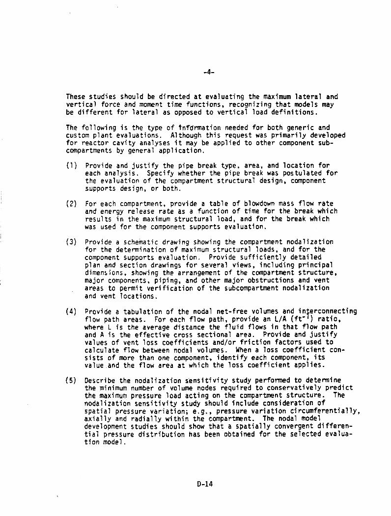
-4-
These studies should be directed at evaluating the maximum lateral andvertical force and moment time functions, recognizing that models maybe different for lateral as opposed to vertical load definitions.
The following is the type of Unfarmation needed for both generic andcustom plant evaluations. Although this request was primarily developedfor reactor cavity analyses it may be applied to other component sub-compartments by general application.
(1) Provide and justify the pipe break type, area, and location foreach analysis. Specify whether the pipe break was postulated forthe evaluation of the compartment structural design, componentsupports design, or both.
(2) For each compartment, provide a table of blowdown mass flow rateand energy release rate as a function of time for the break whichresults in the maximum structural load, and for the break whichwas used for the component supports evaluation.
(3) Provide a schematic drawing showing the compartment nodalizationfor the determination of maximum structural loads, and for thecomponent supports evaluation. Provide sufficiently detailedplan and section drawings for several views, including principaldimensions, showing the arrangement of the compartment structure,major components, piping, and other major obstructions and ventareas to permit verification of the subcompartment nodalizationand vent locations.
(4) Provide a tabulation of the nodal net-free volumes and interconnectingflow path areas. For each flow path, provide an L/A (ft-') ratio,where L is the average distance the fluid flows in that flow pathand A is the effective cross sectional area. Provide and justifyvalues of vent loss coefficients and/or friction factors used tocalculate flow between nodal volumes. When a loss coefficient con-sists of more than one component, identify each component, itsvalue and the flow area at which the loss coefficient applies.
(5) Describe the nodalization sensitivity study performed to determinethe minimum number of volume nodes required to conservatively predictthe maximum pressure load acting on the compartment structure. Thenodalization sensitivity study should include consideration ofspatial pressure variation; e.g., pressure variation circumferentially,axially and radially within the compartment. The nodal modeldevelopment studies should show that a spatially convergent differen-tial pressure distribution has been obtained for the selected evalua-tion model.
D-14

-5-
Describe the justify the nodalization sensitivity study performedfor the major component supports evaluated, if different from thestructural analysis model, where transient forces and moments actingon the components are of concern. Where component loads are ofprimary interest, show the effect of noding variations on thetransient forces and moments. Use this information to justifythe nodal model selected for use in the component supportsevaluation.
If the pressurization of subvolumes located in regions away from thebreak location is of concern for plant safety, show that the selec-tion of parameters which affect the calculations have been conserva-tively evaluated. This is particularly true for pressurization ofthe volume beneath the reactor vessel. In this case, a model whichpredicts the highest pressurization below the vessel should beselected for the evaluation.
NOTE: It has been our experience that for the reactor cavity, threeregions should be considered (i.e., nodalized) when developinga total model. These are:
(1) the volume around or in the vicinity of the break loca-tion out to a radius approximated by the adjacentnozzles, and including portions of the penetration volumefor some plants;
(2) the volume or region covering the upper reactor cavity,primarily the RPV nozzles other than the break nozzle;and
(3) the region encompassing the lower reactor cavity andother portions of the reactor-cavity not included inItems (1) and (2).
(6) Discuss the manner in which movable obstructions to vent flow (suchas insulation, ducting, plugs, and seals) were treated. Provideanalytical and experimental justification that vent areas will notbe partially or completely plugged by displaced objects. Discusshow insulation for piping and components was considered in determiningvolumes and vent areas.
(7) Graphically show the pressure (psia) and differential pressure (psi)response as functions of time for a representative number of nodesto indicate the spatial pressure response. Discuss the basis forestablishing the differential pressure on structures and components.
D-15
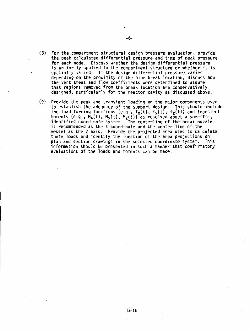
-6-
(8) For the compartment structural design pressure evaluation, providethe peak calculated differential pressure and time of peak pressurefor each node. Discuss whether the design differential pressureis uniformly applied to the compartment structure or whether it isspatially varied. If the design differential pressure variesdepending on the proximity of the pipe break location, discuss howthe vent areas and flow coefficients were determined to assurethat regions removed from the break location are conservativelydesigned, particularly for the reactor cavity as discussed above.
(9) Provide the peak and transient loading on the major components usedto establish the adequacy of the support design. This should includethe load forcing functions (e.g., fx(t), fv(t), fz(t)) and transientmoments (e.g., Mx(t), My(t), Mz(t)) as resolved about a specific,identified coordinate system. The centerline of the break nozzleis recommended as the X coordinate and the center line of thevessel as the Z axis. Provide the projected area used to calculatethese loads and identify the location of the area projections onplan and section drawings in the selected coordinate system. Thisinformation should be presented in such a manner that confirmatoryevaluations of the loads and moments can be made.
.D-16
APPENDIX E
FUEL-SYSTEM DESIGN
(Appendix A to SRP 4.2)
E-1


NUREG-0S00(Formerly NUREG-75/0W7)
R .- U.& NUCLEAR REGULATORY COMMISSION
1STANDARD REVIEW PLANOFFICE OF NUCLEAR REACTOR REGULATION
Appendix E
U.S. Nuclear Regulatory CommissionOffice of Nuclear Reactor Regulation
PROPOSED ADDITION OFAPPENDIX A
EVALUATION OF FUEL ASSEMBLY STRUCTURAL RESPONSETO EXTERNALLY APPLIED FORCES
TOSTANDARD REVIEW PLAN PSRP-4.2, REVISION 2, DRAFT 1
A. BACKGROUND
Earthquakes and postulated pipe breaks in the reactor coolant systemwould result in external forces on the fuel assembly. SRP Section 4.2states that fuel system coolability should be maintained and that damageshould not be so severe as to prevent control rod insertion when requiredduring these low probability accidents. This Appendix describes thereview that should performed of the fuel assembly structural response toseismic and LOCA loads. Background material for this Appendix is givenin Refs. 1-3.
This proposed revision of the Standard Review Plan and the support value/impactstatement have not received a complete staff review and approval and do notrepresent an official NRC staff position. Public comments are being solicitedon both the revision and the value/impact statement (including any implementationschedules) prior to a review by the Regulatory Requirements Review Committeeand their recommendation as to whether this revision should be approved.Comments should be sent to the Secretary of the Commission, U.S. NuclearRegulatory Commission, Washington, D.C. 20555, Attention: Docketing andService Branch. All comments received by will be con-sidered by the Regulatory Requirements Review Committee. A summary of themeeting of the Committee at which this revision is considered, the Committeerecommendations and all of the associated documents and comments considered bythe Committee will be made publicly available prior to a decision by theDirector, Office of Nuclear Reactor Regulation, on whether to implement thisrevision.
USNRC STANDARD REVIEW PLANStandard review plans are prepared for the guidance of the Office of Nuclear Reactor Regulation staff responsible for the review ofapplications to construct and operate nuclear power plants. These documents ure made available to the public as part of theCommission's policy to inform the nuclear industry and the general public of regulatory procedures and policies. Standard reviewplans are not substitutes for regulatory guides or the Commission's regulations and compliance with them is not required. Thestandard review plan sections are keyed to the Standard Format and Content of Safety Analysis Reports for Nuclear Power Plants.Not all sections of the Standard Format have a corresponding review plan.
Published standard review plans will be revised periodically, as appropriate, to accommodate comments and to reflect new informa-tion and experience. E-3Comments and suggestions for Improvement will be considered and should be sent to the U.S. Nuclear Regulatory Commission,Office of Nuclear Reactor Regulation. Washington, D.C. 2M5.
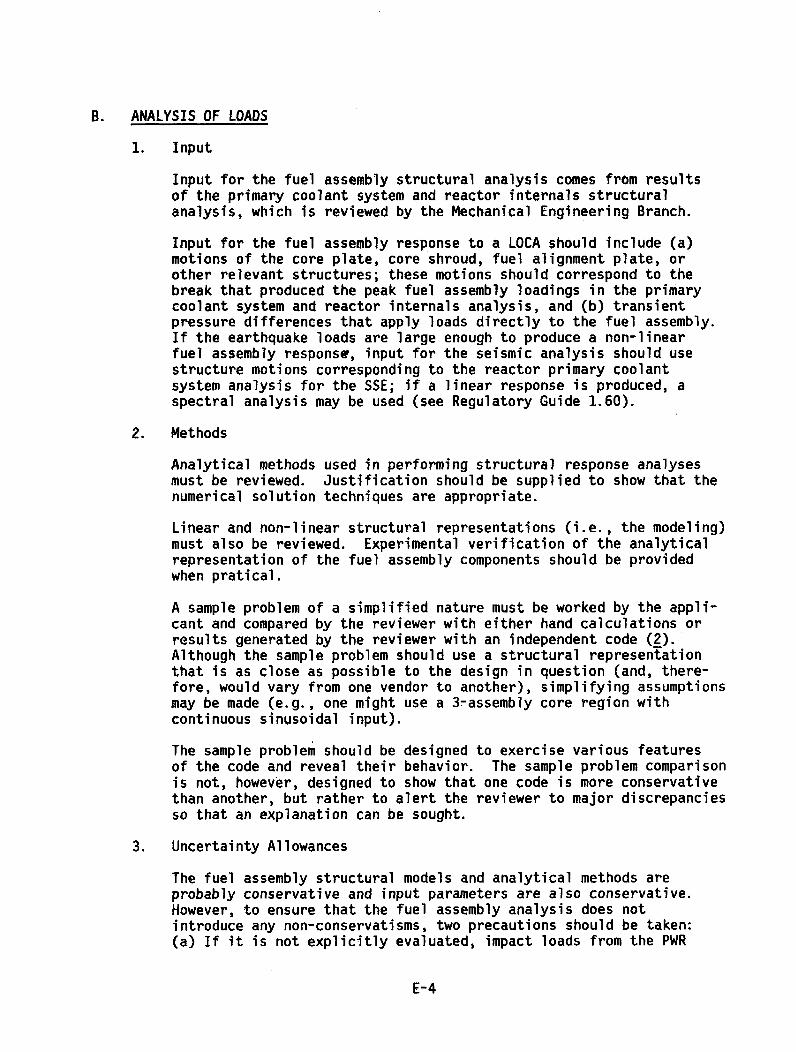
B. ANALYSIS OF LOADS
1, Input
Input for the fuel assembly structural analysis comes from resultsof the primary coolant system and reactor internals structuralanalysis, which is reviewed by the Mechanical Engineering Branch.
Input for the fuel assembly response to a LOCA should include (a)motions of the core plate, core shroud, fuel alignment plate, orother relevant structures; these motions should correspond to thebreak that produced the peak fuel assembly loadings in the primarycoolant system and reactor internals analysis, and (b) transientpressure differences that apply loads directly to the fuel assembly.If the earthquake loads are large enough to produce a non-linearfuel assembly response, input for the seismic analysis should usestructure motions corresponding to the reactor primary coolantsystem analysis for the SSE; if a linear response is produced, aspectral analysis may be used (see Regulatory Guide 1.60).
2. Methods
Analytical methods used in performing structural response analysesmust be reviewed. Justification should be supplied to show that thenumerical solution techniques are appropriate.
Linear and non-linear structural representations (i.e., the modeling)must also be reviewed. Experimental verification of the analyticalrepresentation of the fuel assembly components should be providedwhen pratical.
A sample problem of a simplified nature must be worked by the appli-cant and compared by the reviewer with either hand calculations orresults generated by the reviewer with an independent code (2).Although the sample problem should use a structural representationthat is as close as possible to the design in question (and, there-fore, would vary from one vendor to another), simplifying assumptionsmay be made (e.g., one might use a 3-assembly core region withcontinuous sinusoidal input).
The sample problem should be designed to exercise various featuresof the code and reveal their behavior. The sample problem comparisonis not, however, designed to show that one code is more conservativethan another, but rather to alert the reviewer to major discrepanciesso that an explanation can be sought.
3. Uncertainty Allowances
The fuel assembly structural models and analytical methods areprobably conservative and input parameters are also conservative.However, to ensure that the fuel assembly analysis does notintroduce any non-conservatisms, two precautions should be taken:(a) If it is not explicitly evaluated, impact loads from the PWR
E-4
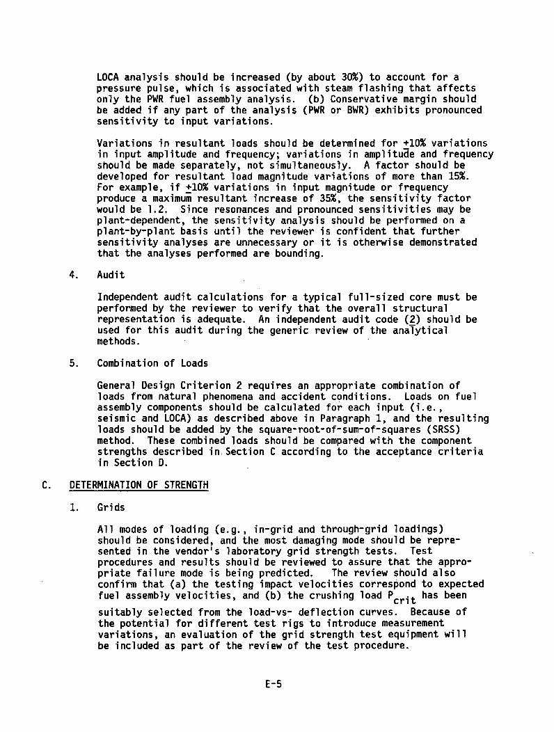
LOCA analysis should be increased (by about 30%) to account for apressure pulse, which is associated with steam flashing that affectsonly the PWR fuel assembly analysis. (b) Conservative margin shouldbe added if any part of the analysis (PWR or BWR) exhibits pronouncedsensitivity to input variations.
Variations in resultant loads should be determined for +10% variationsin input amplitude and frequency; variations in amplitude and frequencyshould be made separately, not simultaneously. A factor should bedeveloped for resultant load magnitude variations of more than 15%.For example, if +10% variations in input magnitude or frequencyproduce a maximum resultant increase of 35%, the sensitivity factorwould be 1.2. Since resonances and pronounced sensitivities may beplant-dependent, the sensitivity analysis should be performed on aplant-by-plant basis until the reviewer is confident that furthersensitivity analyses are unnecessary or it is otherwise demonstratedthat the analyses performed are bounding.
4. Audit
Independent audit calculations for a typical full-sized core must beperformed by the reviewer to verify that the overall structuralrepresentation is adequate. An independent audit code (2) should beused for this audit during the generic review of the analyticalmethods.
5. Combination of Loads
General Design Criterion 2 requires an appropriate combination ofloads from natural phenomena and accident conditions. Loads on fuelassembly components should be calculated for each input (i.e.,seismic and LOCA) as described above in Paragraph 1, and the resultingloads should be added by the square-root-of-sum-of-squares (SRSS)method. These combined loads should be compared with the componentstrengths described in Section C according to the acceptance criteriain Section D.
C. DETERMINATION OF STRENGTH
1. Grids
All modes of loading (e.g., in-grid and through-grid loadings)should be considered, and the most damaging mode should be repre-sented in the vendor's laboratory grid strength tests. Testprocedures and results should be reviewed to assure that the appro-priate failure mode is being predicted. The review should alsoconfirm that (a) the testing impact velocities correspond to expectedfuel assembly velocities, and (b) the crushing load Pcrit has been
suitably selected from the load-vs- deflection curves. Because ofthe potential for different test rigs to introduce measurementvariations, an evaluation of the grid strength test equipment willbe included as part of the review of the test procedure.
E-5

The consequences of grid deformation are small. Gross deformationof grids in many PWR assemblies would be needed to interfere withcontrol rod insertion during an SSE (i.e., buckling of a few isolatedgrids could not displace guide tubes significantly from their properlocation), and grid deformation (without channel deflection) wouldnot affect control blade insertion in a BWR. In a LOCA, grossdeformation of the hot channel in either a PWR or a BWR would resultin only small increases in peak cladding temperature. Therefore,average values are appropriate, and the allowable crushing loadPcrit should be the 95% confidence level on the true mean as taken
from the distribution of measurements on unirradiated productiongrids at (or corrected to) operating temperature. While Pcrit will
increase with irradiation, ductility will be reduced. The extramargin in Pcrit for irradiated grids is thus assumed to offset the
unknown deformation behavior of irradiated grids beyond Pcrit"
2. Components Other than Grids
Strengths of fuel assembly components other than spacer grids may bededuced from fundamental material properties or experimentation.Supporting evidence for strength values should be supplied. Sincestructural failure of these components (e.g., fracturing of guidetubes or fragmentation of fuel rods) could be more serious than griddeformation, allowable values should bound a large percentage (about95%) of the distribution of component strengths. Therefore, ASMEBoiler and Pressure Vessel Code values and procedures may be usedwhere appropriate for determining yield and ultimate strengths.Specification of allowable values may follow the ASME Code require-ments and should include consideration of buckling and fatigueeffects.
D. ACCEPTANCE CRITERIA
1. Loss-of-Coolant Accident
Two principal criteria apply for the LOCA: (a) fuel rod fragmentationmust not occur as a direct result of the blowdown loads, and (b) the10 CFR 50.46 temperature and oxidation limits must not be exceeded.The first criterion is satisfied if the combined loads on the fuelrods and components other than grids remain below the allowablevalues defined above. The second criterion is satisfied by an ECCSanalysis. If combined loads on the grids remain below Pcrit' as
defined above, then no significant distortion of the fuel assemblywould occur and the usual ECCS analysis is sufficient. If combinedgrid loads exceed Pcrit' then grid deformation must be assumed and
the ECCS analysis must include the effects of distorted fuelassemblies. An assumption of maximum credible deformation (i.e.,fully collapsed grids) may be made unless other assumptions arejustified.
E-6
Control rod insertability is a third criterion that must be satisfied.Loads from the worst-case LOCA that requires control rod insertionmust be combined with the SSE loads, and control rod insertabilitymust be demonstrated for that combined load. For a PWR, if combinedloads on the grids remain below Pcrit as defined above, then signi-
ficant deformation of the fuel assembly would not occur and controlrod insertion would not be interfered with by lateral displacementof the guide tubes. If combined loads on the grids exceed Pcrit'
then additional analysis is needed to show that deformation is notsevere enough to prevent control rod insertion.
For a BWR, several conditions must be met to demonstrate controlblade insertability: (a) combined loads on the channel box mustremain below the allowable value defined above for components otherthan grids; otherwise, additional analysis is needed to show thatdeformation is not severe enough to prevent control blade insertion,and (b) vertical liftoff forces must not unseat the lower tieplatefrom the fuel support piece such that the resulting loss of lateralfuel bundle positioning could interfere with control blade insertion.
2. Safe Shutdown Earthquake
Two criteria apply for the SSE: (a) fuel rod fragmentation must notoccur as a result of the seismic loads, and (b) control rod insert-ability must be assured. The first criterion is satisfied by thecriteria in Paragraph 1. The second criterion must be satisfied forSSE loads alone if no analysis for combined loads is required byParagraph 1.
E. REFERENCES
1. R. L. Grubb, "Review of LWR Fuel System Mechanical Response withRecommendations for Component Acceptance Criteria," Idaho NationalEngineering Laboratory, NUREG/CR-IOI8, September 1979.
2. R. L. Grubb, "Pressurized Water Reactor Lateral Core Response Routine,FAMREC (Fuel Assembly Mechanical Response Code)," Idaho NationalEngineering Laboratory, NUREG/CR-1019, September 1979.
3. R. L. Grubb, "Technical Evaluation of PWR Fuel Spacer Grid ResponseLoad Sensitivity Studies," Idaho National Engineering Laboratory,NUREG/CR-1020, September 1979.
E-7


NRC FORM 335 usNN1. REPORT NUMBER (Assignedby DDC)
BIBLIOGRAPHIC DATA SHEET NUREII-06094. TITLE AND SUBTITLE (Add Volume No., if appropriate) 2. (Leave blank)
Asymmetric Blowdown Loads on PWR Primary Systems
Subtitle: Resolution of Generic Task Action Plan A-2 3. RECIPIENT'S ACCESSION NO.
7. AUTHOR(S) S. B. Hosford, 1asK Manager, K. MdtLLu, R. r. 5. DATE REPORT COMPLETEDE. D. Throm, C. G. Tinkler MONTH YEAR
November 19809. PERFORMING ORGANIZATION NAME AND MAILING ADDRESS (Include Zip Code) DATE REPORT ISSUED
Division of Safety Technology ONur
Office of Nuclear Reactor Regulation ny
U.S. Nuclear Regulatory Commission 6. (Leave blank)
Washington, DC 20555 8. (Leave blank)
12. SPONSORING ORGANIZATION NAME AND MAILING ADDRESS (Include Zip Code)10. PROJECT/TASK/WORK UNIT NO.
Same as 9, above.11. CONTRACT NO.
13. TYPE OF REPORT PERIOD COVERED (Inclusive dates)
NUREGn
15. SUPPLEMENTARY NOTES 14. (Leave blank)
Nolne16. ABSTRACT 9200 words or less)
NRC staff, after being informed of newly identffied asymmetric loadings resulting from
postulated ruptures of primary piping, initiated a generic investigation, Task Action
Plan A-2, limited to pressurized-water-reactor (PWR) plants because of their hirherprimary system pressures. The intent of the investigation was to develop acceptablecriteria and auidelitnes for evaluating plant analyses.
The staff concludes that an acceptable basis is provided in this report for performingand reviewing plant analyses. Criteria were developed for evaluatina loadinc transien'structural components, and the fuel assembly.
The staff approved computer proarams and modeling techniques submitted by each PWR venifor development of the subcooled blowdown and cavity-pressure loadina transients Auditmodels were develooed to evaluate the structural computer programs and modelingtechniques. Methods have been approved for the structural-analysis method submittedby Westinghouse for the Indian Point Unit 3 plant. Criteria and guidelines are providito perform a detailed evaluation of the fuel assembly. Acceptance criteria are alsonrovided so deformed fuel-assembly spacer grids may be evaluated.
17. KEY WORDS AND DOCUMENT ANALYSIS 17a. DESCRIPTORS
17b. IDENTIFIERS/OPEN-ENDED TERMS
18. AVAILABILITY STATEMENT 19. SECURITY C.AS (This report 21. NO. OF PAGES
UnclassifiTedUnlimited 20. SECURITY CLASS (This page) 22. PRICElUnclassified $
or
N RC FORM 335 (7-77)