asymmetric lateral sound beaming in a willis medium
TRANSCRIPT

PHYSICAL REVIEW RESEARCH 3, 033080 (2021)
Asymmetric lateral sound beaming in a Willis medium
Xiaoshi Su * and Debasish BanerjeeToyota Research Institute of North America, 1555 Woodridge Avenue, Ann Arbor, Michigan 48105, USA
(Received 18 April 2021; revised 6 July 2021; accepted 8 July 2021; published 22 July 2021)
Willis coupling, also known as pressure-velocity cross coupling, in acoustic materials has received muchattention in the past years. This effect has been found useful in acoustic metasurface designs for wave redirection.We find that Willis coupling in phononic crystals also provides rich physics to manipulate waves. Here, wereport the extreme asymmetric lateral sound beaming effect in a two-dimensional phononic crystal composed ofWillis scatterers. By matching the second-order Bragg scattering with two leaky guided modes (a quadrupoleresonance and a cross-coupling-induced dipole resonance), a normally incident wave is redirected towards thepositive and negative directions orthogonal to the incident wave with different amounts of energy. Simulationand experimental results demonstrate the extraordinary asymmetric lateral beaming effect in the Willis medium.The results presented here may find applications in the design of tunable beam splitters and waveguides.
DOI: 10.1103/PhysRevResearch.3.033080
I. INTRODUCTION
Willis materials are composite materials displaying crosscoupling between strain and momentum [1]. The cross-coupling effect is often referred to as the Willis couplingand usually occurs in inhomogeneous materials [2]. Mucheffort has been made to understand the effect of Williscoupling in elastodynamics [2–5]. Willis coupling also ex-ists in some acoustic media in which the acoustic pressurecouples to the particle velocity [2,5,6]. It is also foundthat Willis coupling is analogous to the bianisotropy inelectromagnetism [2,7]. Hence Willis materials are some-times also referred to as bianisotropic materials. Variousapplications have been reported in elastodynamics, such asnonreciprocal transmission in an active Willis material [8],asymmetric absorption and scattering in a passive Willismaterial [9], and simultaneous control of transmitted andreflected waves using active Willis materials [10]. Highlyefficient acoustic metasurfaces [11] and metagratings [12–16]for sound redirection based on Willis coupling have beenreported. Unidirectional zero reflection and nonreciprocaltransmission of sound have also been demonstrated in Willismaterials [17,18].
In this paper, we report an extraordinary lateral soundbeaming effect in a Willis medium (phononic crystal com-posed of Willis scatterers arranged in a square lattice pattern).It should be noted that the special scattering properties ofthe Willis scatterers are crucial to the realization of theasymmetric lateral sound beaming effect. For a conventional
Published by the American Physical Society under the terms of theCreative Commons Attribution 4.0 International license. Furtherdistribution of this work must maintain attribution to the author(s)and the published article’s title, journal citation, and DOI.
acoustic scatterer, the monopole response (scalar) can onlybe generated by the acoustic pressure (scalar), while thedipole response (vector) can only be generated by the ve-locity (vector). However, due to the cross coupling betweenpressure and velocity, Willis scatterers can also display dipoleresponse under pressure excitation and display monopole re-sponse under velocity excitation [12]. Previously reportedlateral sound beaming effects in phononic crystals are basedon the quadrupole mode, which is symmetric, in the unitcell [19–21]. Therefore, the transmitted beams in the lateraldirections are always symmetric. By using Willis scatterersin the phononic crystal, the pressure excited dipole momentin the unit cell forms an additional antisymmetric mode or-thogonal to the incident wave. By matching the antisymmetricand symmetric modes to the second-order Bragg scattering inthe Willis medium, the asymmetric lateral beaming effect ispossible.
II. PHONONIC CRYSTAL COMPOSED OF WILLISSCATTERERS
The Willis medium for asymmetric lateral beaming pro-posed in this paper is depicted in Fig. 1. Multiple Willisscatterers are arranged in a square lattice manner with lat-tice constant d as shown in Fig. 1(a). The acoustic mediumsurrounding the Willis medium is air, and all the scatterersare considered acoustically rigid. Figure 1(b) shows the ge-ometric parameters of the scatterer in which the inner radiusis denoted by ri, the outer radius is denoted by ro, and theneck width is denoted by w. The sound beaming effect isillustrated in Fig. 1(a): A plane wave is normally incidentalong the +y direction; the wave is then partially reflectedalong the −y direction and partially transmitted through twolateral directions along the ±x axis as well as the +y di-rection. The extreme case of particular interest in this paperis that the energy transmission towards the +x direction ismuch larger than that towards the −x direction. However,
2643-1564/2021/3(3)/033080(6) 033080-1 Published by the American Physical Society

XIAOSHI SU AND DEBASISH BANERJEE PHYSICAL REVIEW RESEARCH 3, 033080 (2021)
FIG. 1. Description of the Willis medium. The material is com-posed of Willis scatterers arranged in a square lattice pattern asshown in (a). A plane wave is normally incident along the +y di-rection from port 1; the transmitted waves can exit from ports 2, 3,and 4. (b) shows the details of the unit cell. The lattice constant isdenoted by d; ri, ro, and w are the inner radius, outer radius, andneck width, respectively.
the scattered waves from conventional scatterers are alwayssymmetric about the incident direction. Therefore, althoughconventional phononic crystals can split waves towardsthe lateral directions, the lateral beaming effect is alwayssymmetric [19–21].
In order to achieve the asymmetric lateral beaming ef-fect, the scattered waves from the scatterers must containasymmetric components. Recent research on Willis acousticscatterers provides a means of generating the dipole momentorthogonal to the incident direction [12,22]. It is found thatthe acoustic pressure can excite a dipole moment orthogonalto the incident direction due to the cross coupling betweenacoustic pressure and particle velocity. This effect has beenutilized to achieve wave cancellation with monopole responsein a metagrating design [12]. In this paper, we consider ahigher frequency range (ka ∼ 1, where k is the wave numberand a = ro) in a phononic crystal and utilize the pressureexcited dipole together with a quadrupole response to achievethe asymmetric lateral beaming outlined in this paper. Thedipole scattering properties of the Willis scatterer designedin this paper along the orthogonal direction are studied andpresented in Fig. 2. The acoustic medium surrounding thescatterer is air with Bulk modulus B = 1.42 MPa and massdensity ρ = 1.204 kg/m3; the scatterer is considered to beacoustically rigid. The scattering coefficients |α′| shown inFig. 2 are calculated using the method described in Ref. [22].Figure 2(a) shows the dipole scattering coefficients alongthe x direction for a wave incident along the ±y direc-tion. The results for a rigid cylinder of the same radius arealso plotted for comparison. Obviously, the pressure exciteddipole moment (orthogonal to the incident direction) fromthe Willis scatterer is more than five orders of magnitudehigher than that from a rigid cylinder. This difference is dueto the fact the Willis scatterer is asymmetric about the yaxis which caused the pressure-velocity cross coupling. Thegeometric parameters of the scatterer are important to thedipole scattering strength under pressure excitation. Due tothe asymmetric internal structure, the dipole scattering coef-ficient corresponding to the pressure excited dipole (|αpv′
x |)
FIG. 2. Normalized dipole scattering coefficients for a normallyincident plane wave along the +y direction. (a) corresponds to theacoustic pressure excited dipole orthogonal to the direction of theincident wave. (b) corresponds to the acoustic velocity excited dipolealong the incident direction. The blue and black lines represent thedipole scattering coefficients for the C-shaped scatterer and a rigidscatterer of the same outer radius, respectively.
orthogonal to the incident direction is significantly increased.Although not shown in Fig. 2, the maximum scattering of thepressure excited dipole occurs near the resonant frequencyaround ka ≈ 0.77 and gradually decreases at higher or lowerfrequencies. The resonant frequency is determined by thegeometric parameters of the scatterer. One can increase theinner radius ri or reduce the neck width w to decrease theresonant frequency. One can also reduce the inner radius orincrease the neck width to increase the resonant frequency.The objective of this paper is not to achieve maximum crosscoupling, and its frequency actually lies outside the fre-quency range of interest. However, it is remarkable that thecross-coupling-induced dipole is still not perturbative at non-resonant frequencies in our design. In fact, the strength of thepressure excited dipole orthogonal to the incident directionis comparable to the strength of the velocity excited dipolealong the incident direction as shown in Fig. 2(b). By tak-ing advantage of the cross coupling in the Willis material,
033080-2

ASYMMETRIC LATERAL SOUND BEAMING IN A WILLIS … PHYSICAL REVIEW RESEARCH 3, 033080 (2021)
FIG. 3. Lateral beaming in periodic structures. (a) is a squarelattice of rigid cylinders; the radius of each cylinder is r = 1.05 cm,and the lattice constant is d = 6.466 cm. (b) illustrates the first anti-symmetric (4924.9 Hz) and symmetric (5283.9 + 173.39i Hz) modesand the corresponding dipole and quadrupole modes in the unit cell.(c) is the simulated sound pressure field at 5305 Hz showing thesymmetric lateral beaming effect in the periodic structure; a Gaussianbeam is normally incident along the +y direction. (d) is a Willismedium composed of C-shaped scatterers; the outer radius of thescatterer is ro = 1.05 cm, and the lattice constant is d = 6.466 cm.(e) shows the two modes similar to those in (b) at two differentfrequencies (5158.3 + 81.583i Hz and 5280.4 + 71.982i Hz) and thecorresponding dipole and quadrupole modes in the unit cell. Thesimulated asymmetric lateral beaming in a Willis medium at 5305 Hzis shown in (f).
the asymmetric lateral beaming effect proposed in Fig. 1 ispossible.
III. ASYMMETRIC LATERAL SOUND BEAMING
A. Lateral sound beaming in a phononic crystal
Previously reported lateral beaming effects for soundwaves in water and flexural waves in plates are all symmet-ric [19–21]. The reason is that the conventional scatterersin those designs are nonbianisotropic (no Willis coupling),so that the antisymmetric modes inside the phononic crystalcannot be excited. Here, we begin with the symmetric lateralsound beaming effect in air and then show that the symme-try can be broken by using Willis scatterers. As shown inFig. 3(a), a cluster of rigid cylinders (8 × 4 array) with radiusr = 1.05 cm are arranged in a square lattice pattern with alattice constant d = 6.466 cm.
For a phononic crystal, the strongest scattering occurswhen the Bragg condition nλ = 2d sin θ is satisfied, where nis a positive integer, θ is the incident angle, and λ is the wave-length. For this specific case in which the sound is normallyincident (θ = 90◦), the second-order Bragg scattering (n = 2)occurs at 5305 Hz. By tuning the radius r of the cylinder, theresonant modes inside the phononic crystal can be adjustedto match the Bragg scattering. The first antisymmetric andsymmetric modes for r = 1.05 cm are displayed in Fig. 3(b).Here, a mode is called symmetric when the mode shape issymmetric about the centerline along the y direction and iscalled antisymmetric when the mode shape is antisymmetricabout the centerline along the y direction. The antisymmetricmode at 4924.9 Hz is a dipole mode in the unit cell, whichcannot be excited by a normally incident sound. However,the symmetric mode at 5283.9 + 173.39i Hz is a quadrupolemode in the unit cell and couples to the incident wave. The
FIG. 4. Measurement results. (a) shows the three-dimensional (3D) printed Willis scatterer; (b) shows the measurement setup of the Willismedia placed in a 2D waveguide (two 11/16-in.-thick acrylic plates of 48 × 48-in. size separated by 2.75 cm in parallel); the 32 scatterersare arranged in a square lattice pattern with a lattice constant of d = 6.466 cm; the open necks of the scatterers are oriented towards the +xdirection; sound pressure fields were measured in three 12.5 × 9.5-cm areas indicated by dashed rectangles (12 cm away from the scatterers).(c) is the simulated sound pressure field at 5305 Hz for a normally incident Gaussian beam along the +y direction; (d)–(f) are the measuredsound pressure fields at 5305 Hz corresponding to the three areas in (b) and (c) marked by dashed rectangles.
033080-3
XIAOSHI SU AND DEBASISH BANERJEE PHYSICAL REVIEW RESEARCH 3, 033080 (2021)
insets in Fig. 3(b) illustrate the relations between the dipolemode in the unit cell and the antisymmetric mode in thescatterer array, and the relations between the quadrupole modein the unit cell and the symmetric mode in the scatterer array.The dipole modes in the unit cells contribute to the antisym-metric mode of the scatterer array; the quadrupole modes inthe unit cells contribute to the symmetric mode of the scattererarray. It is noted that the frequency of the symmetric mode notonly has a real part close to 5305 Hz, but also has an imaginarycomponent. As explained in Ref. [21], the positive imaginarypart of the mode determines its lifetime. A complex resonantfrequency with a large imaginary part means that the lifetimeof the mode is short, which is due to more energy leakage intofree space. In other words, the imaginary part of the modeleads to a substantial spatial effect of the mode, i.e., a leakyguided mode, in a finite phononic crystal. Figure 3(c) showsthe simulation result obtained using COMSOL MULTIPHYSICS at5305 Hz. It is obvious that the beams along the ±x directionsare symmetric since the quadrupole mode is symmetric.
B. Asymmetric lateral sound beaming in a Willis medium
The redirected waves along the two lateral directions canbe asymmetric in a Willis medium thanks to the acousticpressure excited dipole moment orthogonal to the incidentwave. The phononic crystal composed of Willis scatterers isshown in Fig. 3(d). The outer radius of the scatterer is ro =1.05 cm, the inner radius is ri = 0.47 cm, and the neck widthis w = 0.5 cm. The lattice constant is also d = 6.466 cm cor-responding to second-order Bragg scattering at 5305 Hz fornormally incident sound. The geometries are tailored so thatthe two modes shown in Fig. 3(e) are both close to 5305 Hz.The design procedure is described as follows. First, the outerradius ro = 1.05 cm is adopted from the conventional scattererpresented in Sec. III A, which is determined by varying itsvalue to match the frequency of the symmetric mode to thesecond-order Bragg scattering. Then the internal structure ofthe C-shaped scatterer is introduced to couple the antisym-metric mode of the Willis phononic crystal to the incidentwave and provide the possibility to tune the frequency. Thefrequency of the antisymmetric mode can be adjusted bychanging the inner radius ri and neck width w. The neck widthis kept relatively large at 0.5 cm to simplify the design processand reduce the thermoviscous loss. By varying the inner radiusri, we shifted the resonant frequency of the antisymmetricmode close to the second-order Bragg scattering. It can beeasily observed from the mode shapes that they are coupledto the propagating wave along the y direction. Both of thetwo resonant frequencies (5158.3 + 81.583i Hz and 5280.4 +71.982i Hz) have substantial imaginary components, leadingto the spatial effect along the x direction in the finite phononiccrystal. Due to the symmetry (antisymmetry) of the two leakyguided modes, destructive interference along the −x directiondecreases the transmission, while constructive interferencealong the +x direction increases the transmission. Hence theasymmetric lateral beaming effect is achieved as shown in thesimulation results in Fig. 3(f).
It is also interesting to see that the transmission vanishesalong the +y direction. This phenomenon is due to the inter-ference between the incident wave and the scattered waves.
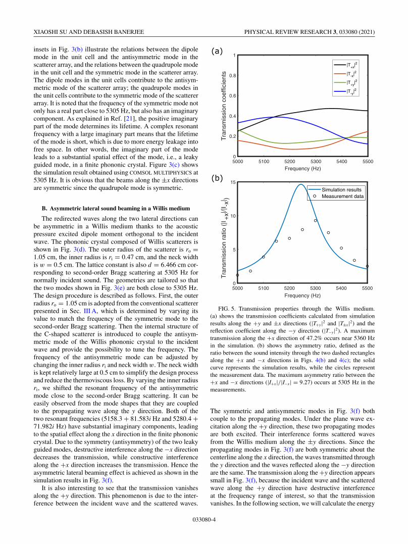
FIG. 5. Transmission properties through the Willis medium.(a) shows the transmission coefficients calculated from simulationresults along the +y and ±x directions (|T+y|2 and |T±x|2) and thereflection coefficient along the −y direction (|T−y|2). A maximumtransmission along the +x direction of 47.2% occurs near 5360 Hzin the simulation. (b) shows the asymmetry ratio, defined as theratio between the sound intensity through the two dashed rectanglesalong the +x and −x directions in Figs. 4(b) and 4(c); the solidcurve represents the simulation results, while the circles representthe measurement data. The maximum asymmetry ratio between the+x and −x directions (|I+x|/|I−x| = 9.27) occurs at 5305 Hz in themeasurements.
The symmetric and antisymmetric modes in Fig. 3(f) bothcouple to the propagating modes. Under the plane wave ex-citation along the +y direction, these two propagating modesare both excited. Their interference forms scattered wavesfrom the Willis medium along the ±y directions. Since thepropagating modes in Fig. 3(f) are both symmetric about thecenterline along the x direction, the waves transmitted throughthe y direction and the waves reflected along the −y directionare the same. The transmission along the +y direction appearssmall in Fig. 3(f), because the incident wave and the scatteredwave along the +y direction have destructive interferenceat the frequency range of interest, so that the transmissionvanishes. In the following section, we will calculate the energy
033080-4

ASYMMETRIC LATERAL SOUND BEAMING IN A WILLIS … PHYSICAL REVIEW RESEARCH 3, 033080 (2021)
propagations along different directions and compare themwith measurement results.
C. Experimental results
Acoustic measurements were done to demonstrate the per-formance of the asymmetric lateral beaming effect. A totalnumber of 32 scatterers were fabricated by using stereolithog-raphy of gray resin. The scatterer is fabricated in two partswith a body 2.6 cm tall and a cover 0.15 cm thick as shownin Fig. 4(a). The Young’s modulus of the fabricated structureis E = 2.8 GPa, and the density is ρ = 1.78 kg/m3. Theexperimental apparatus shown in Fig. 4(b) is the same asthat used in Ref. [23], except that the distance between thetop and bottom plates of the waveguide is now 2.75 cm.The scatterers are arranged in a square lattice pattern with alattice constant of d = 6.466 cm. The speaker array 30 cmaway from the scatterers generates a plane wave ranging from3 to 7 kHz. Sound pressure fields were measured in three12.5 × 9.5-cm areas as marked in Fig. 4(c). Note that Fig. 4(c)is the simulation result at 5305 Hz for reference (the sameas Fig. 4). The measured pressure fields at 5305 Hz in theaforementioned three areas are plotted in Figs. 4(d)–4(f). Aswe can see, the simulated sound wave is incident along the+y direction and transmits through the structure along the +xdirection. The measured pressure fields are normalized to themaximum amplitude in the three areas. The amplitude of thepressure field in Fig. 4(f) is significantly higher than that inFigs. 4(d) and 4(e). The results clearly show the asymmetriclateral beaming effect in the fabricated structures. To quantifythe asymmetric lateral beaming effect, we calculated the sim-ulated energy transmission and reflection coefficients alongfour directions (±x and ±y). The energy propagating alongfour directions was computed by integrating the intensity Iover the four sides of the phononic crystal resulting in theenergy E = ∫
I · ndL. The results are plotted in Fig. 5(a).The maximum transmission towards the +x direction is about47.2% at 5360 Hz. Due to the limitations of our measure-ment system, only limited areas along three directions weremeasured, so that the corresponding coefficients cannot becalculated using the measurement data. However, we directlycomputed the ratio of the energy flux in the +x direction to theenergy flux in the −x direction using measurement data and
compared it with that calculated in the simulation. The resultsare presented in Fig. 5(b). The measurement result showsa maximum ratio of 9.27 at 5305 Hz between the energytransmitted in the +x direction and the energy transmitted inthe −x direction. It is noted that the simulation data yielda maximum ratio of about 14.7 near 5240 Hz. The overallshapes of the two curves match well except that the simulationresult has a sharper peak shifted away from 5305 Hz. Thedifference between the measurement data and the simulationresults is likely due to the alignment error of the scatterers.The distances between the scatterers are slightly different,and their open necks are not perfectly oriented towards the+x direction, which may reduce the Bragg scattering and thestrength of the resonant modes. Another reason is thatthe pressure field is not evenly distributed along the y axis;more energy may be redirected to areas near the dashedrectangular areas and change the energy flux ratio in the mea-surement results. Other than the aforementioned discrepancy,our design shows a broadband asymmetric lateral beamingeffect with an energy transmission ratio of at least 5 within5125–5400 Hz.
IV. CONCLUSIONS
In conclusion, we presented an extraordinary asymmetriclateral beaming effect in a phononic crystal composed ofWillis scatterers arranged in a square lattice manner. Theasymmetric lateral beaming effect is achieved by matchingthe dipole and quadrupole modes with Bragg scattering,where the dipole response orthogonal to the incident wave isexcited by the pressure field. The wave numbers of the afore-mentioned two modes both have relatively large imaginarycomponents and hence display a spatial effect as leaky guidedmodes. Furthermore, the interference between the symmetricand antisymmetric modes causes asymmetry in the transmis-sion pattern. The experimental results presented in this papershow a maximum intensity ratio of 9.27 at the design fre-quency. In addition, the structures can be easily rotated so thatthe maximum transmission direction can be easily switchedtowards other directions. We envision future applications inbeam splitter and waveguide designs.
[1] J. R. Willis, Variational principles for dynamic prob-lems for inhomogeneous elastic media, Wave Motion 3, 1(1984).
[2] C. F. Sieck, A. Alù, and M. R. Haberman, Origins of Williscoupling and acoustic bianisotropy in acoustic metamateri-als through source-driven homogenization, Phys. Rev. B 96,104303 (2017).
[3] G. W. Milton and J. R. Willis, On modifications of Newton’ssecond law and linear continuum elastodynamics, Proc. R. Soc.A 463, 855 (2007).
[4] A. N. Norris, A. L. Shuvalov, and A. A. Kutsenko, An-alytical formulation of 3D dynamic homogenization forperiodic elastic systems, Proc. R. Soc. A 468, 1629(2012).
[5] M. B. Muhlestein, C. F. Sieck, A. Alù, and M. R. Haberman,Reciprocity, passivity and causality in Willis materials, Proc. R.Soc. A 472, 20160604 (2016).
[6] M. B. Muhlestein, C. F. Sieck, P. S. Wilson, and M. R.Haberman, Experimental evidence of Willis coupling in a one-dimensional effective material element, Nat. Commun. 8, 15625(2017).
[7] S. Koo, C. Cho, J.-H. Jeong, and N. Park, Acoustic omni meta-atom for decoupled access to all octants of a wave parameterspace, Nat. Commun. 7, 13012 (2016).
[8] H. Nassar, X. C. Xu, A. N. Norris, and G. L. Huang,Modulated phononic crystals: Non-reciprocal wave propaga-tion and Willis materials, J. Mech. Phys. Solids 101, 10(2017).
033080-5

XIAOSHI SU AND DEBASISH BANERJEE PHYSICAL REVIEW RESEARCH 3, 033080 (2021)
[9] Y. Liu, Z. Liang, J. Zhu, L. Xia, O. Mondain-Monval, T. Brunet,A. Alù, and J. Li, Willis Metamaterial on a Structured Beam,Phys. Rev. X 9, 011040 (2019).
[10] Y. Chen, X. Li, G. Hu, M. R. Haberman, and G. Huang, Anactive mechanical Willis meta-layer with asymmetric polariz-abilities, Nat. Commun. 11, 3681 (2020).
[11] J. Li, C. Shen, A. Diaz-Rubio, S. A. Tretyakov, and S. A.Cummer, Systematic design and experimental demonstra-tion of bianisotropic metasurfaces for scattering-free ma-nipulation of acoustic wavefronts, Nat. Commun. 9, 1342(2018).
[12] L. Quan, Y. Ra’di, D. L. Sounas, and A. Alù, Maximum WillisCoupling in Acoustic Scatterers, Phys. Rev. Lett. 120, 254301(2018).
[13] S. R. Craig, X. Su, A. Norris, and C. Shi, Experimental Real-ization of Acoustic Bianisotropic Gratings, Phys. Rev. Appl. 11,061002(R) (2019).
[14] Z. Hou, X. Fang, Y. Li, and B. Assouar, Highly Efficient Acous-tic Metagrating with Strongly Coupled Surface Grooves, Phys.Rev. Appl. 12, 034021 (2019).
[15] Y. Fu, C. Shen, Y. Cao, L. Gao, H. Chen, C. T. Chan, S. A.Cummer, and Y. Xu, Reversal of transmission and reflectionbased on acoustic metagratings with integer parity design, Nat.Commun. 10, 2326 (2019).
[16] Y. K. Chiang, S. Oberst, A. Melnikov, L. Quan, S. Marburg, A.Alù, and D. A. Powell, Reconfigurable Acoustic Metagratingfor High-Efficiency Anomalous Reflection, Phys. Rev. Appl.13, 064067 (2020).
[17] A. Merkel, V. Romero-Garciá, J.-P. Groby, J. Li, and J.Christensen, Unidirectional zero sonic reflection in passive PT-symmetric Willis media, Phys. Rev. B 98, 201102(R) (2018).
[18] Y. Zhai, H.-S. Kwon, and B.-I. Popa, Active Willis metama-terials for ultracompact nonreciprocal linear acoustic devices,Phys. Rev. B 99, 220301(R) (2019).
[19] X. Bai, C. Qiu, H. He, S. Peng, M. Ke, and Z. Liu, Extraordinarylateral beaming of sound from a square-lattice phononic crystal,Phys. Lett. A 381, 886 (2017).
[20] A. S. Titovich and A. N. Norris, Acoustic Poisson-like effect inperiodic structures, J. Acoust. Soc. Am. 139, 3353 (2016).
[21] P. Gao, J. Sánchez-Dehesa, and L. Wu, Poisson-like effect forflexural waves in periodically perforated thin plates, J. Acoust.Soc. Am. 144, 1053 (2018).
[22] X. Su and A. N. Norris, Retrieval method for the bianisotropicpolarizability tensor of Willis acoustic scatterers, Phys. Rev. B98, 174305 (2018).
[23] X. Su and D. Banerjee, Extraordinary Sound Isolation Using anUltrasparse Array of Degenerate Anisotropic Scatterers, Phys.Rev. Appl. 13, 064047 (2020).
033080-6