at ^mtite g^tion
TRANSCRIPT

RAMB6LL ENVIRONMENT& HEALTH
William Willets, PEChief, Permitting Section, Division of Air QualityNC Department of Environmental Quality1641 Mail Service Center
Raleigh, NC 27609-1641
/ Received ^SEP tf ? 2020
At ̂mtite g^tion
Re: Title V Permit Renewal and Modification ApplicationEnviva Pellets Ahoskie, LLC
Ahoskie, North Carolina
Hertford CountyPermit No. : 10121T04Facility ID: 4600107
Dear Mr. Willets:
August 28, 2020
Ram boll
8235 YMCA Plaza DriveSuite 300Baton Rouge, LA 70810USA
T +1 225-4082691www. ramboll. com
Enclosed please find a North Carolina Department of Environment Quality (NCDEQ)application package for renewal of the Title V permit and modifications proposed forEnviva Pellets Ahoskie, LLC ("Enviva", "the Ahoskie plant", or "the facility") (NCDEQ Facility ID 4600107) inHertford County. The facility currently operates under Air Quality Permit No. 10121T04 issued by theNCDEQ, Division of Air Quality (DAQ) on June 6, 2016. The proposed modifications are being implementedto meet new customer softwood percentage and production rate demands and to implement significantemission reductions at the facility.
The Ahoskie plant is currently permitted as a major source with respect to the Title V and New SourceReview (NSR) permitting programs because potential facility-wide emissions of one or more criteriapollutants are estimated to exceed the major source thresholds of 100 tons per year (tpy) and 250 tpy,respectively. The plant is currently permitted as a minor source of hazardous air pollutants (HAP). As aresult of the significant emission reductions being proposed as part of this modification, the Ahoskie plant'spotential emissions will be less than the Prevention of Significant Deterioration (PSD) major sourcethreshold; thus, the facility will be classified as a minor source for PSD. The facility will continue to beclassified as a major source under the Title V program and will remain a minor source of HAP.
With this application, Enviva is proposing the following modifications:
. Increase production rate from 481, 800 oven dried tons (ODT) per year to 630, 000 ODT peryear;
. Adjust percentage of softwood processed to a facility-wide maximum of 100% annually;
. Reconfigure the wood yard area as follows: add three (3) truck tippers, add one (1) freshreclaim hopper and one (1) mixed reclaim hopper, add automation including a stacker/reclaimersystem to reduce manual handling using frontend loaders, include new conveyor drop
1/4
RAMBC5LL
points/material transfers, remove existing conveyor drop points/material transfers, remove theexisting electric powered green wood chipper (IES-CHP1) and the existing debarker, and updateemissions to reflect the proposed changes. The existing ID for green wood handling and storagewill be renamed from IES-GWHS to ES-GWHS;
Add three (3) green hammermills for a total of four (4) green hammermills (ES-GHM-1 throughES-GHM-4) and route the green hammermills exhaust to the inlet duct of the existing wetelectrostatic precipitator (CD-WESP) and proposed RTO (CD-RTO). The existing greenhammermill will be renamed from IES-CHP2 to ES-GHM-1;
Add a regenerative thermal oxidizer (CD-RTO) to the existing dryer (ES-DRYER) following theexisting WESP (CD-WESP). The existing WESP stack will be replaced with the proposed RTOstack (CD-RTO);
Add two (2) double duct burners (IES-DDB-1 and IES-DDB-2), one on the dryer duct from thecyclone outlet to the ID fan and the other on the dryer duct for exhaust gas redrculation to theWESP to reduce the risk of fire;
Incorporate the existing dryer and furnace bypass stacks and associated emissions (ES-FURNACEBYP) into the permit;
Update the source ID for dried wood handling from IES-DWH to ES-DWH;
Add two (2) dry hammermills (ES-DHM-6 and ES-DHM-7) and two (2) associated materialcollection cyclones and route the exhaust from ES-DHM-6 to existing fabric filter CD-DHM-FF1and the exhaust from ES-DHM-7 to existing fabric filter CD-DHM-FF2;
Control emissions of volatile organic compounds (VOC) and HAPs from the existing andproposed new dry hammermills by routing a portion of the exhaust from each dry hammermillback to the front end of the dry hammermill. All exhaust gases ultimately exiting the dryhammermills will be routed to either the dryer (ES-DRYER) furnace, the dryer WESP (CD-WESP), or a combination of the two prior to entering the dryer RTO (CD-RTO) for control;
Addition of additive handling and storage to the list of insignificant activities (IES-ADD);
Remove the existing insignificant emissions source pellet press system (IES-PP) from the permitbecause emissions from the transfer of material from pellet mills to the pellet mills collectionconveyor are included in the pellet cooler (ES-CLR1 through ES-CLR6) exhaust;
Add two (2) pellet mills, one (1) pellet cooler (ES-CLR6), and one (1) simple cyclone (CD-CLR-4) and route exhaust from all existing and new pellet mills, pellet coolers, multicyclones, andsimple cyclones to a proposed quench duct, followed by a proposed RTO/RCO (CD-RCO);
Include the dry shavings system ID (IES-DRYSHAVE) to recognize emissions associated with thereceipt and handling of dry shavings;
Include the existing dry shavings hammermill and associated material recovery cyclone as anemission source (ES-DSHM). A portion of the dry shavings hammermill exhaust is recirculatedback to the front of the dry shavings hammermill. The remaining exhaust is routed to the dried
2/4
RAMB LL
wood day silo (ES-DWDS). ES-DWDS exhausts to bin filter vent (CD-DWDS-BV) which will berouted to the pellet mitl/pellet cooler proposed quench duct and R.TO/RCO (CD-RCO);
. Upsize the finished product handling pellet screen to accommodate the proposed productionincrease;
. Add two (2) existing diesel storage tanks (IES-TK-3 and IES-TK-4). IES-TK-3 is used to fillmobile equipment in the wood yard and the fire pump diesel engine tank (IES-TK-2). IES-TK-4is used to provide fuel for front-end loaders and other facility equipment;
. Add a compressed natural gas (CNG) terminal (IES-CNGT) as a backup to the natural gassupply for the proposed RTO (CD-RTO), RTO/RCO (CD-RCO), and double duct burners (IES-DDB-1 and IES-DDB-2);
. Rename source IDs for the diesel storage tanks from IST-1 and IST-2 to IES-TK-1 and IES-TK-2;
. Remove the hammermill area from source ID ES-DHM-5 and create a separate source ID, dustcontrol system (ES-DCS), to reflect the emissions that are not attributable to the dryhammermill 5 (ES-DHM-5); and
. Update criteria pollutant and HAP emissions factors.
Enviva is submitting this Title V renewal and modification application pursuant to the requirements of ISANCAC 02Q . 0513 (Permit Renewal and Expiration) and ISA NCAC 02Q . 0516 (Significant PermitModification) and in accordance with the procedures of ISA NCAC 2Q .0501(c)(l). As required, three (3)copies of the complete permit renewal/modification application package and an application processing feefor a permit modification in the amount of $988 will be submitted via electronic payment. In addition,Enviva has submitted the required zoning determination documents to the Town of Ahoskie Planning andZoning Administrator. A copy of the submitted zoning consistency determination request is included as anappendix to the application.
Thank you for your prompt attention to this matter. If you have any questions regarding this request,please contact me at (225) 408-2691 or Kai Simonsen, Air Permit Engineer at Enviva, at (984)789-3628.
Yours sincerely,
Michael CarbonManaging PrincipalAir Sciences
D 225-408-2691M [email protected]
3/4

RAMB LL
ec: Yana Kravtsova (Enviva)Stephen Stroud (Enviva)Kai Simonsen (Enviva)Steven Van Ootegham (Enviva)
Enclosures: Permit Application including Appendices
4/4

Prepared for
Enviva Pellets Ahoskie, LLCHertford County, North Carolina
Prepared ByRamboll US CorporationBaton Rouge, Louisiana
Project Number
1690014763-009
DateAugust 2020
li%
<^1
RAMB LL

Renewal and Modification ApplicationEnviva Pellets Ahoskie, LLC
Hertford County, North Carolina
CONTENTS
1. INTRODUCTION 1
2. PROCESS DESCRIPTION 42. 1 Green Wood Handling and Storage (ES-GWHS), Bark Hog (IES-BARK), and Green
Wood Fuel Storage Bin (IES-GWFB) 42. 2 Green Hammermills (ES-GHM-1 through ES-GHM-4) 42. 3 Dryer (ES-DRYER) and Double Duct Burners (IES-DDB-1 and IES-DDB-2) 52. 4 Furnace Bypass Stack (ES-FURNACEBYP) and Dryer Bypass Stack 52. 5 Dried Wood Handling (ES-DWH), Dry Hammermills (ES-DHM-1 through ES-DHM-7),
and Dust Control System (ES-DCS) 62. 6 Pellet Mill Feed Silo (ES-PMFS) 72. 7 Additive Handling and Storage (IES-ADD) 72. 8 Pellet Mills and Pellet Coolers (ES-CLR1 through ES-CLR6) 82. 9 Dry Shavings Handling and Storage (IES-DRYSHAVE), Dried Wood Day Silo (ES-
DWDS), and Dry Shavings Hammermill (ES-DSHM) 82. 10 Finished Product Handling (ES-FPH), Fines Bin (ES-FB), Pellet Loadout (ES-PL1 and
ES-PL2) and Truck Loadout Bin (ES-TLB) 82. 11 Emergency Generator (IES-EG), Fire Water Pump Engine (IES-FWP), and Diesel
Storage Tanks (IES-TK-1, IES-TK-2, IES-TK-3, and IES-TK-4) 92. 12 Compressed Natural Gas (CNG) Terminal (IES-CNGT) 9
3. POTENTIAL EMISSIONS QUANTIFICATION 103. 1 Green Wood Handling and Storage (ES-GWHS) 103. 2 Green Wood Storage Piles and Bark Fuel Storage Piles (ES-GWHS) 103. 3 Bark Hog (IES-BARK) 103.4 Green Wood Fuel Storage Bin (IES-GWFB) 113. 5 Dryer (ES-DRYER), Green Hammermills (ES-GHM-1 through ES-GHM-4), Dry
Hammermills (ES-DHM-1 through ES-DHM-7), and the Dust Control System (ES-DCS) 11
3. 6 Furnace Bypass - Cold Start-up (ES-FURNACEBYP) 113. 7 Furnace Bypass - Idle Mode (ES-FURNACEBYP) 123. 8 Double Duct Burners (IES-DDB-1 and IES-DDB-2) 123. 9 Dried Wood Handling (ES-DWH) 123. 10 Dry Shavings Reception, Handling, and Silo (IES-DRYSHAVE) 133. 11 Pellet Mill Feed Silo (ES-PMFS) 133. 12 Additive Handling and Storage (IES-ADD) 133. 13 Dry Shavings Hammermilt (ES-DSHM), Dried Wood Day Silo (ES-DWDS), and Pellet
Mills and Pellet Coolers (ES-CLR1 through ES-CLR6) 133. 14 Fines Bin (ES-FB), Truck Loadout Bin (ES-TLB), Pellet Loadout (ES-PL1 and ES-PL2),
and Finished Product Handling (ES-FPH) 143. 15 Emergency Generator (IES-EG) and Fire Water Pump Engine (IES-FWP) 143. 16 Diesel Storage Tanks (IES-TK-1, IES-TK-2, IES-TK-3, and IES-TK-4) 143. 17 Haul Roads 14
4. STATE AND FEDERAL PERMITTING APPLICABILITY 164. 1 Federal Permitting Programs 164. 1. 1 New Source Review 164. 1. 2 Title V Operating Permit Program 17
Contents

Renewal and Modification ApplicationEnviva Pellets Ahoskie, LLC
Hertford County, North Carolina
4. 2 North Carolina Permitting Program 17
5. REGULATORY APPLICABILITY 185. 1 New Source Performance Standards 185. 1. 1 40 CFR 60 Subpart A - General Provisions 185. 1. 2 40 CFR 60 Subpart Dc - Standards of Performance for Small Industrial-
Commercial-Institutional Steam Generating Units 185. 1. 3 40 CFR 60 Subpart Kb - Standards of Performance for Volatile Organic Liquid
Storage Vessels 185. 1.4 40 CFR 60 Subpart CCCC - Standards of Performance for Commercial and Industrial
Solid Waste Incineration Units 185. 1. 5 40 CFR 60 Subpart IIII - Standards of Performance for Stationary Compression
Ignition Internal Combustion Engines 195. 2 National Emission Standards for Hazardous Air Pollutants 195. 2. 1 40 CFR 63 Subpart A - General Provisions 195. 2. 2 40 CFR 63 Subpart B - Requirements for Control Technology Determinations for
Major Sources in Accordance with Clean Air Act Section 112(g) 195. 2. 3 40 CFR 63 Suboart DDDD - NESHAP for Plywood and Composite Wood Products 205. 2. 4 40 CFR 63 Subpart ZZZZ - NESHAP for Stationary Reciprocating Internal
Combustion Engines 205. 2. 5 40 CFR 63 Subpart JJJJJJ - NESHAP for Industrial, Commercial, and Institutional
Boilers at Area Sources 205. 3 Compliance Assurance Monitoring 215. 4 Chemical Accident Prevention Provisions 225. 5 North Carolina Administrative Code 22
5. 5. 1 15A NCAC 02D . 0504 Particulates from Wood Burning Indirect Heat Exchangers 225. 5. 2 15A NCAC 02D . 0515 Particulates from Miscellaneous Industrial Processes 225. 5. 3 15A NCAC 02D . 0516 Sulfur Dioxide Emissions from Combustion Sources 245. 5. 4 15A NCAC 02D . 0521 Control of Visible Emissions 245. 5. 5 ISA NCAC 02D .0540 Particulate from Fugitive Dust Emission Sources 245. 5. 6 15ANCAC02D . 1100 Control of Toxic Air Pollutant Emissions 24
6. TOXICS MODELING ANALYSIS 256. 1 State Requirements 256. 2 Acceptable Ambient Levels 256. 3 Model Selection 276. 4 Receptor Grid and Elevation Data 276. 5 Meteorological Data 276. 6 Modeled Operating Conditions 276. 6. 1 Normal Operation 276. 6. 2 Furnace Bypass - Cold Start-ups and Planned Shutdown 276. 6. 3 Furnace Bypass - Idle Mode 286. 6. 4 Dryer Bypass 286. 7 Modeled Sources and Release Parameters 286. 7. 1 Point Sources 296. 7. 2 Area Sources 296. 8 GEP Stack Height Analysis 306. 9 Building Downwash 306. 10 Modeling Results 30
Contents

Renewal and Modification ApplicationEnviva Pellets Ahoskie, LLC
Hertford County, North Carolina
LIST OF TABLES
Table 4-1: Change in Potential to Emit
Table 5-1: Process Weight Limits for Ahoskie Emission Points
Table 6-1: Comparison to Toxic Air Pollutant Permitting Emission Rates
Table 6-2: Summary of Modeled Point Source Parameters
Table 6-3: Summary of Modeled Area Source Parameters
Table 6-4: Comparison of Maximum Modeled Concentrations from 2018 to the AALs
APPENDICES
Appendix A - Area Map
Appendix B - Process Flow Diagram
Appendix C - Potential Emissions Calculations
Appendix D - Permit Application Forms
Appendix E - CAM Plans
Appendix F - Supporting Documentation for TAP Modeling Analysis
Appendix G - Modeled Source Layout
Appendix H - Zoning Consistency Determination Request
Contents

Renewal and Modification ApplicationEnviva Pellets Ahoskie, LLC
Hertford County, North Carolina
ACRONYMS AND ABBREVIATIONS
AAL
AP-42
bhp
BMP
CAA
CAM
CFR
CI
co
DAQ
EPA
FSC
HAP
hpICE
Ib
MACT
MMBtu
NAAQS
NCAC
NCASI
NCDEQ
NESHAP
NNSR
NOx
NSPS
NSR
NWS
ODT
PEFC
PM
Acceptable Ambient Level
Compilation of Air Pollutant Emission Factors
brake horsepower
Best Management Practice
Clean Air Act
Compliance Assurance Monitoring
Code of Federal Regulations
Compression Ignition
Carbon Monoxide
Division of Air Quality
US Environmental Protection Agency
Forest Stewardship Council
Hazardous Air Pollutant
horsepower
Internal Combustion Engine
Pound
Maximum Achievable Control Technology
Million British thermal units
National Ambient Air Quality Standards
North Carolina Administrative Code
National Council for Air and Stream Improvement
North Carolina Department of Environmental Quality
National Emission Standards for Hazardous Air Pollutants
Nonattainment New Source Review
Nitrogen Oxides (NO + N02)
New Source Performance Standards
New Source Review
National Weather Service
Oven Dried short Tons
Programme for the Endorsement of Forest Certifications
Particulate Matter
Acronyms and Abbreviations Ramboll

Renewal and Modification ApplicationEnviva Pellets Ahoskie, LLC
Hertford County, North Carolina
ACRONYMS AND ABBREVIATIONS (Continued)
PM2.5
PMio
PSD
PSEU
RICE
RCO
RTO
SIP
S02
SFI
TAP
TCO
tph
tpy
voc
WESP
Particulate Matter Less Than 2. 5 Micrometers in Aerodynamic Diameter
Particulate Matter Less Than 10 Micrometers in Aerodynamic Diameter
Prevention of Significant Deterioration
Pollutant-Specific Emission Unit
Reciprocating Internal Combustion Engine
Regenerative Catalytic Oxidizer
Regenerative Thermal Oxidizer
State Implementation Plan
Sulfur Dioxide
Sustainable Forestry Initiative
Toxic Air Pollutant
Thermal Catalytic Oxidizer
tons per hour
tons per year
Volatile Organic Compounds
Wet Electrostatic Precipitator
Acronyms and Abbreviations Ramboll

Renewal and Modification ApplicationEnviva Pellets Ahoskie, LLC
Hertford County, North Carolina
1. INTRODUCTION
Enviva Pellets Ahoskie, LLC (Enviva) owns and operates a wood pellet manufacturing plant(referred to herein as "the Ahoskie plant", "the plant", or "the facility") in Hertford County,North Carolina. The plant currently operates under Air Quality Permit No. 10121T04 issued bythe North Carolina Department of Environmental Quality (NCDEQ), Division of Air Quality(DAQ) on June 6, 2016. The plant consists of the following processes: Log Chipper, Bark Hog,Green Hammermill, Rotary Dryer, Dry Hammermills, Pellet Mills and Coolers, Product Loadoutoperations and other ancillary activities.
The Ahoskie plant is currently permitted as a major source with respect to the Title V and NewSource Review (NSR) permitting programs because potential facility-wide emissions of one ormore criteria pollutants were estimated to exceed the major source thresholds of 100 tons peryear (tpy) and 250 tpy, respectively. The plant is currently permitted as a minor source ofhazardous air pollutants (HAP).
Enviva is submitting this renewal and modification application pursuant to the requirements ofISA NCAC 02Q .0513 (Permit Renewal and Expiration) and 15A NCAC 02Q .0516 (SignificantPermit Modification) and in accordance with the procedures of 15A NCAC 2Q .0501(c)(l). Theproposed modifications are being implemented to meet new customer softwood percentageand production rate demands and to significantly reduce emissions from the facility. Becauseof the emission reductions proposed as part of this modification, the Ahoskie plant's potentialemissions will be less than the Prevention of Significant Deterioration (PSD) major sourcethreshold; thus, the facility will be classified as a PSD minor source. The facility will continueto be classified as a major source under the Title V program and remain a minor source ofHAP.
The following summarizes the proposed changes associated with this permit renewal andmodification application:
. Increase production rate from 481,800 oven dried tons (ODT) per year to 630,000 ODTper year;
. Adjust percent of softwood processed to a facility-wide maximum of 100% annually;
. Reconfigure the wood yard area as follows: add three (3) truck tippers, add one (1) freshreclaim hopper and one (1) mixed reclaim hopper, add automation including astacker/reclaimer system to reduce manual handling using frontend loaders, include newconveyor drop points/material transfers, remove existing conveyor drop points/materialtransfers, remove the existing electric powered green wood chipper (IES-CHP1) and theexisting debarker, and update emissions to reflect the proposed changes. The existing IDfor green wood handling and storage will be renamed from IES-GWHS to ES-GWHS;
. Add three (3) green hammermills for a total of four (4) green hammermills (ES-GHM-1through ES-GHM-4) and route the green hammermills exhaust to the inlet duct of theexisting wet electrostatic precipitator (CD-WESP) and proposed RTO (CD-RTO). Theexisting green hammermill will be renamed from IES-CHP2 to ES-GHM-1;
. Add a regenerative thermal oxidizer (CD-RTO) to the existing dryer (ES-DRYER) followingthe existing WESP (CD-WESP). The existing WESP stack will be replaced with the proposedRTO stack (CD-RTO);
Introduction

Renewal and Modification ApplicationEnviva Pellets Ahoskie, LLC
Hertford County, North Carolina
Add two (2) double duct burners (IES-DDB-1 and IES-DDB-2), one on the dryer duct fromthe cyclone outlet to the ID fan and the other on the dryer duct for exhaust gasrecirculation to the WESP to reduce the risk of fire;
Incorporate the existing dryer and furnace bypass stacks and associated emissions (ES-FURNACEBYP) into the permit;
Update the source ID for dried wood handling from IES-DWH to ES-DWH;
Add two (2) dry hammermills (ES-DHM-6 and ES-DHM-7) and two (2) associated materialcollection cyclones and route the exhaust from ES-DHM-6 to existing fabric filter CD-DHM-FF1 and the exhaust from ES-DHM-7 to existing fabric filter (CD-DHM-FF2);
Control emissions of volatile organic compounds (VOC) and HAPs from the existing andproposed new dry hammermills by routing a portion of the exhaust from each dryhammermill back to the front end of the dry hammermill. All exhaust gases ultimatelyexiting the dry hammermills will be routed to either the dryer (ES-DRYER) furnace, thedr/er WESP (CD-WESP), or a combination of the two, prior to entering the dryer RTO (CD-RTO) for control;
Addition of additive handling and storage to the list of insignificant activities (IES-ADD);
Remove the existing insignificant emissions source pellet press system (IES-PP) from thepermit, as emissions from the transfer of material from pellet mills to the pellet millscollection conveyor are included in the pellet cooler (ES-CLR1 through ES-CLR6)exhaust;
Add two (2) pellet mills, one (1) pellet cooler (ES-CLR6), and one (1) simple cyclone (CD-CLR-4) and route exhaust from all existing and new pellet mills, pellet coolers,multicyclones, and simple cyclones to a proposed quench duct, followed by a proposedRTO/RCO (CD-RCO);
Include the dry shavings system ID (IES-DRYSHAVE) to recognize emissions associatedwith the receipt and handling of dry shavings;
Include the existing dry shavings hammermill and associated material recovery cyclone asan emission source (ES-DSHM). A portion of the dry shavings hammermill exhaust isrecirculated back to the front of the dry shavings hammermill. The remaining exhaust isrouted to the dried wood day silo (ES-DWDS). ES-DWDS exhausts to bin filter vent (CD-DWDS-BV) which will be routed to the pellet mill/pellet cooler proposed quench duct andRTO/RCO (CD-RCO);
Upsize the finished product handling pellet screen to accommodate the proposedproduction increase;
Add two (2) existing diesel storage tanks (IES-TK-3 and IES-TK-4). IES-TK-3 is used to fillmobile equipment in the wood yard and the fire pump diesel engine tank (IES-TK-2). IES-TK-4 is used to provide fuel for front-end loaders and other facility equipment;
Add a compressed natural gas (CNG) terminal (IES-CNGT) as a backup to the natural gassupply for the proposed RTO (CD-RTO), RTO/RCO (CD-RCO), and double duct burners(IES-DDB-1 and IES-DDB-2);
Rename source IDs for the diesel storage tanks from IST-1 and IST-2 to IES-TK-1 andIES-TK-2;
Introduction

Renewal and Modification ApplicationEnviva Pellets Ahoskie, LLC
Hertford County, North Carolina
. Remove the hammermill area from source ID ES-DHM-5 and create a separate source ID,dust control system (ES-DCS), to reflect emissions that are not attributable to dryhammermill 5 (ES-DHM-5); and
. Update criteria pollutant and HAP emissions factors.
A description of the process is provided in Section 2 and methodologies used to quantifypotential emissions are summarized in Section 3. Section 4 describes the applicability offederal and state permitting programs. Section 5 includes a detailed applicability analysis ofboth federal and state regulations. Section 6 includes the Air Toxics Modeling Analysis.Appendix A includes an Area Map, Appendix B includes the Process Flow Diagram, Appendix Cincludes the Potential Emission Calculations, Appendix D includes the completed PermitApplication Forms, Appendix E includes the Compliance Assurance Monitoring (CAM) Plans,Appendix F includes Supporting Documentation for TAP Modeling Analysis, and Appendix Gincludes the Modeled Source Layout. A copy of the submitted zoning consistencydetermination request is included in Appendix H.
Introduction

Renewal and Modification ApplicationEnviva Pellets Ahoskie, LLC
Hertford County, North Carolina
2. PROCESS DESCRIPTIO
Enviva manufactures wood pellets for use as a renewable fuel for energy generation andindustrial customers. Enviva's customers use wood pellets in place of coal, significantlyreducing emissions of pollutants such as lifecycle C02/greenhouse gases, mercury, arsenic andlead. The company is dedicated to improving the environmental profile of energy generationwhile promoting sustainable forestry in the southeastern United States. Enviva holdscertifications from the Forest Stewardship Council (FSC), Sustainable Forestry Initiative (SFI),Programme for the Endorsement of Forest Certification (PEFC), and Sustainable BiomassProgram (SBP). Enviva requires that all suppliers adhere to state-developed "BestManagement Practices" (BMPs) in their activities to protect water quality and sensitiveecosystems. In addition, Enviva is implementing an industry leading "track and trace" systemto further ensure that all fiber resources come from responsible harvests. Enviva paysparticular attention to: land use change, use and effectiveness of BMPs, wetlands,biodiversity, and certification status. All of this combined ensures that Enviva's forestryactivities contribute to healthy forests both today and in the future. A detailed description ofEnviva's Responsible Wood Supply Program can be found at:https://www.envivabiomass.com/sustainabilifr//responsible-sourcing/responsible-sourcing-policy/
The following sections provide a description of the Ahoskie plant process. An area map andprocess flow diagram are provided in Appendices A and B, respectively.
2. 1 Green Wood Handling and Storage (ES-GWHS), Bark Hog (IES-BARK), andGreen Wood Fuel Storage Bin (IES-GWFB)"Green" (i. e., fresh cut) pre-chipped wood and bark are delivered to the plant via trucks fromcommercial harvesting and chipping operations and removed from the trucks using four (4)truck tippers. Oversized green wood material is removed from the pre-chipped wood and istransferred to the bark fuel storage pile for use in the furnace as fuel. Pre-chipped wood fordrying is transferred by front end loader to the green wood storage piles and/or mixed woodstorage pile. From the storage piles, the pre-chipped wood is placed into either the freshreclaim hopper or the mixed reclaim hopper for processing in the green hammermills.
Purchased bark is removed from trucks using a truck tipper and the bark is then transferredby front end loader to the bark fuel storage pile for use as furnace fuel. The bark andoversized green wood material are placed into the bark reclaimer hopper for transfer throughthe fuel screener where oversized material is separated and hogged in the bark hog (IES-BARK) prior to being utilized as fuel. Following the fuel screener and bark hog, the bark andwood chips are transferred to an enclosed green wood fuel storage bin (IES-GWFB) where thematerial is pushed into the furnace. All transfer points and storage piles associated with thewood yard are captured by the green wood handling and storage source (ES-GWHS).
Pre-dried wood, also referred to as Dry Shavings, is received by truck, unloaded by a trucktipper, transferred to storage and processing by front end loader.
2. 2 Green Hammermills (ES-GHM-1 through ES-GHM-4)
Prior to drying, chips from the green softwood and/or mixed wood storage piles will beprocessed in the green hammermills to reduce material to the proper size. In this application,Enviva is requesting approval to construct and operate three (3) new green hammermills (fora total of four (4) units) at the Ahoskie plant. Also, pursuant to this application, Enviva is
Process Description

Renewal and Modification ApplicationEnviva Pellets Ahoskie, LLC
Hertford County, North Carolina
requesting to remove the existing green hammermill (IES-CHP2) from the InsignificantActivities List and include all green hammermills as emissions sources (ES-GHM-1 through ES-GHM-4). Emissions from the green hammermills will be routed for control to the existing dryerWESP (CD-WESP) and the proposed dryer RTO (CD-RTO).
2.3 Dryer (ES-DRYER) and Double Duct Burners (IES-DDB-1 and IES-DDB-2)The existing dryer (ES-DRYER) uses direct contact heat provided to the system via a 175.3million British thermal unit per hour (MMBtu/hr) total heat input furnace that uses bark andoversized wood chips as fuel.
Green wood is fed into the dryer where moisture content is reduced to the desired level androuted to a simple cyclone for material recovery. Exhaust from the cyclone is routed to theexisting dryer WESP (CD-WESP) for particulate, metallic HAP, and hydrogen chloride removal.
In order to reduce VOC and HAP emissions from the dryer and other sources, the Ahoskieplant is proposing to construct and operate a RTO (CD-RTO). The dryer RTO will receive theexhaust from the existing dryer WESP (CD-WESP) to control VOC and HAP emissionsgenerated during drying operations. Pursuant to this application, the dryer RTO (CD-RTO) willalso receive exhaust from the green hammermill and dry hammermill operations (refer toSections 2. 2 and 2. 5 for additional details).
As exhaust gas exits the dryer and begins to cool, wood tar (i. e., pitch) can condense and coatthe inner walls of the dryer ducts creating a risk of fire. To prevent build-up of pitch and thusreduce the risk of fire, the two dryer ducts (herein referred to as double ducts) will be heated.The duct from the cyclone outlet to the ID fan will be heated by one low-NOx burner with amaximum heat input rating of 2. 5 MMBtu/hr. A second 2. 5 MMBtu/hr low-NOx burner will beused to heat the duct used for exhaust gas recirculation to the WESP. The double duct burners(IES-DDB-1 and IES-DDB-2) will combust natural gas and will exhaust directly to atmosphere.
2.4 Furnace Bypass Stack (ES-FURNACEBYP) and Dryer Bypass Stack
Bypass stacks for the dryer and furnace may be used to exhaust hot gases during start-ups(for temperature control), shutdowns, and malfunctions. Specifically, the furnace bypass stack(ES-FURNACEBYP) will be used in the following situations:
. Cold Start-ups: The furnace bypass stack is used when the furnace is started up froma cold shutdown until the refractory is sufficiently heated and can sustain operations at alow level (approximately 15% of the maximum heat input rate). The bypass stack is thenclosed, and the furnace is slowly brought up to a normal operating rate. Use of thefurnace bypass stack for cold start-ups will be limited to 50 hours per year at 26.3MMBtu/hr. Diesel fuel may be used as an accelerant for cold start-ups. The amount usedper event is typically 15 - 30 gallons and the annual usage is typically 100 - 200 gallons.Emissions resulting from diesel usage during cold start-ups are insignificant.
. Idle mode: The furnace may also operate up to 500 hours per year in idle mode withemissions routed to the furnace bypass stack. The purpose of operation in idle mode is tomaintain the temperature of the fire brick lining the furnace which may be damaged if itcools too rapidly. Operation in "idle mode" also significantly reduces the amount of timerequired to restart the furnace. Use of the furnace bypass stack for idle mode will belimited to 500 hours per year at 15 MMBtu/hr.
. Planned Shutdown: In the event of a planned shutdown, the furnace heat input isdecreased and all remaining fuel is moved through the system to prevent a fire. The
Process Description

Renewal and Modification ApplicationEnviva Pellets Ahoskie, LLC
Hertford County, North Carolina
2.5
remaining fuel is combusted prior to opening the furnace bypass stack. The furnacebypass stack is not utilized until after the furnace achieves an idle state (15 MMBtu/hr orless). Until this time, emissions continue to be controlled by the WESP and RTO.
. Malfunction: The furnace automatically aborts to the bypass stack in the event of amalfunction. Aborts may be triggered by failsafe interlocks associated with the furnace ordryer and emissions control systems or utility supply systems (i. e., electricity,compressed air, water/fire protection). As soon as the furnace aborts it automaticallyswitches to "idle mode" (defined as operation at up to a maximum heat input rate of 15MMBtu/hr), the fuel feed is stopped, and the heat input rate drops rapidly.
Conditions under which the dryer bypass stack will be used are as follow:
. Cold Start-ups and Transition from Furnace Idle: The dryer bypass stack is usedwhen the furnace is started up from a cold shutdown and when the furnace transitions
from idle mode to normal operation. Emissions are vented through the dryer bypassstack for approximately 10 minutes as exhaust flow is transitioned from the furnacebypass stack to the WESP and RTO. The dryer is not operational during this time andemissions are due solely to combustion of fuel in the furnace. Emissions during thesebrief transition periods are not separately quantified to avoid double-counting, as theseemissions are already included under the furnace cold start-up and idle mode scenarios.
. Malfunction: The dryer system automatically aborts due to power failure, equipmentfailure, or furnace abort. For example, if the RTO goes offline because of an interlockfailure, the dryer will immediately abort. Dryer abort may also occur if the dryertemperature is out of range, or if a spark is detected.
. Planned Shutdown: During planned shutdowns, as remaining fuel is combusted by thefurnace, the Operator reduces the chip input to the dryer. When only a small amount ofchips remains, the dryer drum is emptied. The dryer bypass stack is then opened, and apurge air fan is used to ensure no explosive build-up occurs in the drum. Emissionsduring this time are negligible and have not been quantified, as the furnace is directed toits abort stack (see furnace planned shutdown above) and the dryer is no longeroperating.
Malfunctions are infrequent, unpredictable, and minimized to the maximum extent possible.They cannot be permitted, as they are, by definition, unplanned events. These emissionscannot reasonably be quantified and are not included in facility-wide potential emissions.
Dried Wood Handling (ES-DWH), Dry Hammermills (ES-DHM-1 through ES-DHM-7), and Dust Control System (ES-DCS)
Dried wood from the dryer material recovery cyclone is conveyed to the dry hammermills viathe dried wood handling system. The dried wood handling emission source (ES-DWH) consistsof partially enclosed conveyor systems, conveyor transfer points along the post-dryerconveyance system, an enclosed screener, and dry hammermill surge bins. Due to updatedemissions estimates, this source will no longer be considered insignificant and therefore Envivarequests the ID be changed from IES-DWH to ES-DWH.
Dried wood is routed to one of seven (7) dry hammermills (ES-DHM-1 through ES-DHM-7) forfurther size reduction prior to pelletization. The Ahoskie plant is currently permitted to operatefive (5) dry hammermills; however, Enviva is requesting authorization to construct andoperate two (2) additional dry hammermills with this application. Each existing and proposed
Process Description

Renewal and Modification ApplicationEnviva Pellets Ahoskie, LLC
Hertford County, North Carolina
dry hammermill includes an associated material recovery cyclone that is routed to one of three(3) baghouses (CD-DHM-FF1 through CD-DHM-FF3) for particulate matter (PM) control. Theexhaust from ES-DHM-6 will be routed to existing fabric filter CD-DHM-FF1 and the exhaustfrom ES-DHM-7 will be routed to existing fabric filter CD-DHM-FF2.
As previously discussed, Enviva is proposing to control VOC emissions from the dryhammermills using a new RTO (CD-RTO) that will be installed downstream of the existingdryer WESP. An air flow recirculation process will be implemented to route a portion of theexhaust from each dry hammermill cyclone back into the front end of the respective dryhammermill to reduce fresh intake air and thus decrease the volume of air that is routed to
the downstream control devices. The dry hammermill exhaust will be routed to baghouses,followed by a quench duct and then to either the dryer furnace (ES-DRYER), the dryer WESP(CD-WESP), or a combination of the two, before entering the RTO (CD-RTO). The purpose ofthe quench duct is to protect the RTO by reducing the risk of fire. Interlocks will be installed tocease operation of the dry hammermills if a minimum flow rate is not maintained in thequench duct or if the furnace/WESP/RTO system ceases normal operation.
At all times 100% of the dry hammermill exhaust will be controlled by a baghouse, WESP, andRTO. The furnace is not a control device and has no impact on estimated potential to emit.The WESP will provide a reduction in PM and metallic HAP and the RTO will provide a reductionin VOC and organic HAP/TAP emissions. The highest pollutant inlet loading to the controldevices will occur when the furnace and dryer are operating at maximum capacity with all dryhammermill exhaust routed to the inlet of the furnace. The quench system is consideredinherent process equipment that is required to safely operate the RTO (i. e., reduce fire risk)and is not a control device.
Milled wood from the dry hammermill material recovery cyclones is transferred to the encloseddry hammermill system discharge collection drag chain conveyor, then to the pellet mill feedsilo infeed drag chain conveyor, and then to the pellet mill feed silo infeed screw conveyor.The dust control system (ES-DCS) collects PM from the dry hammermill area, including somedust from the underside of the post-dryer conveyor system. The collected material is routed tothe existing dry hammermill baghouse, CD-DHM-FF3. Enviva is creating the dust controlsystem source (ES-DCS) to reflect emissions associated with the dry hammermill areacurrently permitted in source (ES-DHM-5). The hammermill area should thus be removed fromsource ES-DHM-5.
2. 6 Pellet Mill Feed Silo (ES-PMFS)
As previously noted, milled wood from the dry hammermill material recovery cyclones istransferred via a set of conveyors to the pellet mill feed silo (ES-PMFS) prior to pelletization.Particulate emissions from the pellet mill feed silo are controlled by a baghouse (CD-PMFS-BV).
2.7 Additive Handling and Storage (IES-ADD)Additive may be used in pellet production to act as a lubricant for the dies and increase the
durability of the final product. Additive is currently received in 2, 000 pound (Ib) supersacksand emptied into a hopper. The additive is transferred from the hopper via an enclosed screwconveyor and is added to milled wood from the pellet mill feed silo discharge screw conveyorprior to transfer to the pellet mills. Because of the minimal particulate matter emissions, theadditive Handling and Storage (IES-ADD) activities are an insignificant activity. The additivecontains no hazardous chemicals orVOCs.
Process Description

Renewal and Modification ApplicationEnviva Pellets Ahoskie, LLC
Hertford County, North Carolina
2.8 Pellet Mills and Pellet Coolers (ES-CLR1 through ES-CLR6)Milled wood is mechanically compacted through presses in the pellet mills. Pursuant to thisapplication, exhaust from the pellet mills and pellet mill conveyors will be vented through thepellet cooler aspiration material recovery cyclones (CD-CLR-C1 through CD-CLR-C4) andpollutant controls as described below, and then to the atmosphere.
Formed pellets are currently discharged into one of five (5) pellet coolers (ES-CLR1 throughES-CLR5). With this application, Enviva is proposing to install two (2) additional pellet millsand one (1) pellet cooler (ES-CLR6) for a total of twelve (12) pellet mills and six (6) pelletcoolers. Similar to the existing pellet coolers, one (1) simple cyclone (CD-CLR-C4) is beingproposed to receive the air stream from the two (2) new pellet mills and one (1) new pelletcooler (ES-CLR6). Following the material recovery cyclones (CD-CLR-C1 through CD-CLR-C4),the captured material is conveyed to a rotary feeder to the high pressure blow line (HPBL)thatroutes the material to the pellet mill feed silo (ES-PMFS). All exhaust from the pellet mills andpellet coolers is proposed to be routed to a quench duct and RTO/RCO (CD-RCO) to reduceVOC and MAP emissions prior to venting to the atmosphere. The quench duct is consideredinherent process equipment that is required for the RTO/RCO (CD-RCO) to operate safely(reduce the risk of fire). A safety interlock will be installed to cease operation of the pelletmills and coolers if a minimum flow rate is not maintained or the RTO/RCO is not ready foroperation. The RTO/RCO will operate in catalytic mode with thermal mode as a back-up duringcatalyst cleaning.
2. 9 Dry Shavings Handling and Storage CIES-DRYSHAVE), Dried Wood Day Silo(ES-DWDS), and Dry Shavings Hammermill (ES-DSHM)In addition to green chips, purchased dry wood and shavings are used to produce pellets,forgoing the green hammermill and drying processes and thus minimizing on-site VOC andHAP emissions. The purchased dry wood/shavings are unloaded from trucks via a truck tipper.The purchased dry wood/shavings are transported via frontend loader to a covered storagepile from which they are fed to a dedicated dry shavings hammermill (ES-DSHM). The milledpurchased dry wood/shavings exiting the dedicated dry shavings hammermill are conveyed toa rotary valve where the material enters the HPBL for transfer to the dried wood day silo (ES-DWDS). Emissions from loading and unloading of the silo are controlled by the dry wood daysilo bin vent filter (CD-DWDS-BV). From the dried wood day silo, the milled dry shavings aretransferred to the pellet mill feed silo (ES-PMFS) for further processing.
Pursuant to this application, Enviva is requesting to include the existing dry shavings handlingand storage source (IES-DRYSHAVE) and the existing dry shavings hammermill (ES-DSHM) inthe permit. Currently, exhaust from the dry shavings hammermill is routed to a materialrecovery cyclone. A portion of the cyclone exhaust is recirculated back to the front of the dryshavings hammermill (ES-DSHM) and the remainder of the exhaust gases are routed to thedried wood day silo (ES-DWDS) that is controlled by the dry wood day silo bin vent filter (CD-DWDS-BV). Pursuant to this application, Enviva is proposing to route the dry wood day silo binvent filter (CD-DWDS-BV) exhaust stream to the proposed quench duct and RTO/RCO (CD-RCO) to reduce VOC and HAP emissions from the dry shavings hammermill (ES-DSHM).
2. 10 Finished Product Handling (ES-FPH), Fines Bin (ES-FB), Pellet Loadout (ES-PL1 and ES-PL2) and Truck Loadout Bin (ES-TLB)Following the pellet coolers, pellets are conveyed to finished product handling (ES-FPH) wherethe final product is conveyed across a pellet screener, onto a collection conveyor, and then to
Process Description

Renewal and Modification ApplicationEnviva Pellets Ahoskie, LLC
Hertford County, North Carolina
a bucket elevator where it is dropped through pipe chutes onto a belt that feeds the truckloadout bin (ES-TLB). From the bin, pellets are gravity fed onto two (2) transfer belts perloading station which transfer pellets to a shuttle belt that drops pellets into trucks throughone of two (2) covered chutes (ES-PL1 and ES-PL2). Finished product handling (ES-FPH),truck loadout bin (ES-TLB), and pellet loadout (ES-PL1 and ES-PL2) emissions are vented intothe finished product handling baghouse (CD-FPH-BF) as a fire prevention measure to preventany build-up of dust on surfaces within the finished product handling building. Fines from thefinished product handling baghouse (CD-FPH-BF) are directed through an air lock to the HPBLand pneumatically transferred to the fines bin (ES-FB) which is controlled by a separatebaghouse (CD-FB-BV). Collected fines are reintroduced into the pellet production process.
2. 11 Emergency Generator (IES-EG), Fire Water Pump Engine (IES-FWP), andDiesel Storage Tanks (IES-TK-1, IES-TK-2, IES-TK-3, and IES-TK-4)The plant has a 350 brake horsepower (bhp) diesel-fired emergency generator (IES-GN) foremergency operations and a 300 bhp diesel-fired fire water pump engine (IES-FWP). Asidefrom maintenance and readiness testing, the generator and fire water pump engines are onlyutilized for emergency operations.
The plant also includes several diesel storage tanks. With this application, Enviva proposes torename two (2) existing tanks that are in the permit from IST-1 and IST-2 to IES-TK-1 andIES-TK-2 and add two (2) other existing diesel storage tanks to the permit (IES-TK-3 and IES-TK-4). Diesel for the existing emergency generator (IES-EG) is stored in a tank of up to 2, 500gallons capacity (IES-TK-1) and diesel for the fire water pump engine is stored in a tank of upto 500 gallon capacity (IES-TK-2). IES-TK-3 (up to 600 gallon capacity) is used to fill mobileequipment in the wood yard and the fire pump diesel engine tank (IES-TK-2). IES-TK-4 (up to1, 000 gallon capacity) is used to provide fuel for front-end loaders and other facilityequipment.
2. 12 Compressed Natural Gas (CNG) Terminal (IES-CNGT)With this application, Enviva is proposing to add a compressed natural gas (CNG) terminal(IES-CNGT). CNG will serve as a backup fuel to the primary fuel, natural gas, which will beused for combustion by the burners in the dryer RTO (CD-RTO), the pellet cooler RTO/RCO(CD-RCO), and the two double duct burners (IES-DDB-1 and IES-DDB-2).1 Note that there areno quantifiable emissions from this source and it is therefore classified as an insignificantactivity in accordance with ISA NCAC 02Q. 0503(8).
1 Any activity whose emissions would not violate any applicable emissions standard and whose potential emissionsof criteria pollutants before air control devices are each no more than 5 tpy and whose potential uncontrolledHAP emissions are each below 1, 000 pounds per year are considered insignificant per 15A NCAC 02Q . 0503(8).
Process Description

Renewal and Modification ApplicationEnviva Pellets Ahoskie, LLC
Hertford County, North Carolina
3. POTENTIAL E ISSIONS QUANTIFICATION
The following summarizes the data sources and calculation methodologies used to quantifypotential emissions from the Ahoskie plant. Detailed potential emissions calculations areprovided in Appendix C. Note that Enviva has quantified potential greenhouse gas (GHG)emissions from all applicable emissions sources; however, GHG emission are not discussed indetail below. Detailed emission calculations for GHG emissions are provided in Appendix C.
3. 1 Green Wood Handling and Storage (ES-GWHS)
Particulate emissions will occur during chip and bark receiving, conveying, and handlingoperations. Fugitive PM emissions from chip and bark transfer operations were calculatedbased on AP-42 Section 13. 2. 4, Aggregate Handling and Storage Piles. 2 Detailed potentialemission calculations are provided in Appendix C.
3. 2 Green Wood Storage Piles and Bark Fuel Storage Piles (ES-GWHS)Particulate emission factors used to quantify potential emissions from storage pile winderosion of the green wood storage piles and bark fuel storage piles were calculated based onUSEPA's Control of Open Fugitive Dust Sources.3 The number of days with rainfall greater than0. 01 inch was obtained from AP-42 Section 13. 2. 2, Unpaved RoadsA, and the percentage oftime that wind speeds exceeds 12 miles per hour (mph) was determined based onmeteorological data from Northampton, North Carolina. The conservative mean silt content of8. 4% for unpaved roads at lumber mills from AP-42 Section 13. 2. 2 was applied in the absenceof site-specific data. The exposed surface area of the pile was calculated based on worst-casepile dimensions.
VOC emissions from storage piles were quantified based on the exposed surface area of thepile and emission factors from the National Council for Air and Stream Improvement (NCASI).5NCASI emission factors range from 1. 6 to 3. 6 pounds (Ib) VOC as carbon/acre-day; however,emissions were conservatively based on the maximum emission factor. Detailed potentialemission calculations are provided in Appendix C.
3.3 Bark Hog (IES-BARK)
PM emissions occur as a result of bark processing. Potential PM emissions from the bark hog(IES-BARK) were quantified based on emission factors from EPA's AIRS Facility SubsystemSource Classification Codes and Emission Factor Listing for Criteria Air Pollutants for SourceClassification Code (SCC) 3-07-008-01 (Log Debarking). 6 All PM was assumed to be largerthan 2. 5 microns in diameter. PM emissions from the bark hog are minimal due to the highmoisture content of green wood (~50%). VOC and methanol emissions were quantified based
2 USEPA AP-42 Section 13. 2. 4, Aggregate Handling and Storage Piles (11/06).3 USEPA Control of Open Fugitive Dust Sources, Research Triangle Park, North Carolina, EPA-450/3-88-008.
September 1988.
4 USEPA AP-42 Section 13. 2. 2, Unpaved Roads (11/06).5 NCASI. Technical Bulletin No. 700. Preliminary Investigation of Releases of Volatile Organic Compounds from
Wood Residual Storage Piles. October 1995.
6 USEPA. Office of Air Quality Planning and Standards. AIRS Facility Subsystem Source Classification Codes andEmission Factor Listing for Criteria Air Pollutants. EPA 450/4-90-003. March 1990.
Potential Emissions Quantification 10

Renewal and Modification ApplicationEnviva Pellets Ahoskie, LLC
Hertford County, North Carolina
on emission factors for log chipping from AP-42 Section 10. 6. 3, Medium Density Fiberboard.7Detailed potential emission calculations for the bark hog are provided in Appendix C.
3.4 Green Wood Fuel Storage Bin (IES-GWFB)
Bark is transferred from the fuel storage piles via a walking floor to a covered conveyor andthen to the fully enclosed green wood fuel storage bin (IES-GWFB). Due to complete enclosureof the green wood fuel storage bin (IES-GWFB), emissions from transfer of material into thebin were not specifically quantified.
3. 5 Dryer (ES-DRYER), Green Hammermills (ES-GHM-1 through ES-GHM-4), DryHammermills CES-DHM-1 through ES-DHM-7), and the Dust Control System(ES-DCS)
Exhaust from the dryer will be routed to a WESP and RTO (CD-RTO) for control of PM, VOC,and HAP. The green hammermills will share the dryer's existing WESP and proposed RTO forcontrol of PM, VOC, and HAP. For potential-to-emit emissions estimates, green hammermillemissions are accounted for under the dryer WESP and RTO (CD-RTO). Exhaust from the dryhammermills and dust control system (ES-DCS), which also includes aspiration from theunderside of the post-dryer conveyor system, will also be controlled by the dryer WESP andthe proposed RTO (CD-RTO). Emissions from the dry hammermills and dust control systemare therefore also accounted for under the dryer RTO (CD-RTO). Emissions of CO, NOx, VOC,and PM are based on emission factors developed from process knowledge and engineeringjudgment. Potential emissions of sulfur dioxide (S02) from green wood combustion werecalculated based on the heat input of the furnace and an emission factor for wood combustion
from AP-42, Section 1. 6, Wood Residue Combustion in Boilers. HAP and toxics air pollutant(TAP) emissions were calculated based on emission factors from AP-42 Section 1. 6, WoodResidue Combustion in Boilers, 8 and factors based on process knowledge and engineeringjudgment.
Emissions of CO and NOx generated during thermal oxidization ofVOC in the dry hammermillexhaust stream by the RTO were calculated based on AP-42 Section 1.4, Natural GasCombustion and the maximum high heating value of the anticipated VOC constituents.9
Emissions from natural gas combustion by the RTO were calculated based on AP-42 Section1. 4, Natural Gas Combustion10 and NC DAQ's Wood Waste Combustion Spreadsheet."Detailed emission calculations are provided in Appendix C.
3.6 Furnace Bypass - Cold Start-up (ES-FURNACEBYP)Potential emissions of CO, NOx, S02, PM, VOC, and HAP for furnace and dryer bypass duringcold start-up were calculated based on emission factors from AP-42 Section 1. 6, Wood ResidueCombustion in Boilers.12 Emissions were based on a maximum heat input value of 26.3MMBtu/hr for the furnace and 50 hours per year of operation. As previously described inSection 2, during cold start-ups emissions may be released through the dryer bypass stack for
7 USEPA AP-42 Section 10. 6.3, Medium Density Fiberboard Manufacturing (08/02).8 USEPA AP-42 Section 1. 6, Wood Residue Combustion in Boilers (09/03).9 USEPA AP-42 Section 1. 4, Natural Gas Combustion (07/98).10 USEPA AP-42 Section 1. 4, Natural Gas Combustion (07/98).n NCDAQ Wood Waste Combustion Spreadsheet for a wood stoker boiler. Available online at:
https;//files. nc. gov/ncdeq/Air°/o20Quality/permits/files/WWC_rev_K_20170308. xlsx.
12 U5EPA AP-42 Section 1. 6, Wood Residue Combustion in Boilers (09/03).
Potential Emissions Quantification 11

Renewal and Modification ApplicationEnviva Pellets Ahoskie, LLC
Hertford County, North Carolina
approximately 10 minutes during transition from the furnace bypass stack to the WESP andRTO. Emissions during these brief transition periods are insignificant and are not separatelyquantified to avoid double-counting, as they are already included under the 50 hours per yearof furnace bypass during cold start-up.
Diesel fuel may be used as an accelerant for cold start-ups; however, as the amount used perevent is typically 15 - 30 gallons and the annual usage is typically 100 - 200 gallons,emissions resulting from the use of diesel fuel are insignificant and are not included in the ES-FURNACEBYP emission estimates. Detailed potential emission calculations are provided inAppendix C.
3. 7 Furnace Bypass - Idle Mode (ES-FURNACEBYP)The furnace will operate up to 500 hours per year in "idle mode", which is defined as operationup to a maximum heat input rate of 15 MMBtu/hr. During this time, emissions will exhaust outof the furnace bypass stack. Potential emissions of CO, NOx, S02, PM, VOC, and HAP werecalculated based on emission factors from AP-42 Section 1. 6, Wood Residue Combustion inBoilers. 13 As previously described in Section 2, as the furnace ramps up from idle mode tonormal operation, emissions may be released through the dryer bypass stack forapproximately 10 minutes during transition from the furnace bypass stack to the WESP andRTO. Emissions during these brief transition periods are insignificant and are not separatelyquantified to avoid double-counting, as they are already included under the 500 hours peryear of furnace bypass during idle mode. Detailed potential emission calculations are providedin Appendix C.
3.8 Double Duct Burners (IES-DDB-1 and IES-DDB-2)Emissions from natural gas combustion by the double duct burners (IES-DDB-1 and IES-DDB-2) were calculated based on AP-42 Section 1.4, Natural Gas Combustion14 and NC DAQ's WoodWaste Combustion Spreadsheet. 15
Per 15A NCAC 02Q . 0503(8), the double duct burners (IES-DDB-1 and IES-DDB-2) areconsidered insignificant activities because potential uncontrolled criteria pollutant emissionsare less than 5 tpy and potential uncontrolled MAP emissions are each less than 1, 000 poundsper year (Ib/yr). Detailed emission calculations are provided in Appendix C.
3.9 Dried Wood Handling (ES-DWH)
As previously described in Section 2, dried wood handling (ES-DWH) consists of partiallyenclosed conveyor systems, conveyor transfer points located along the post-dryer conveyancesystem, and a dry hammermill surge bin. Particulate emissions from dried wood handlingmaterial transfer points were calculated using AP-42, Section 13. 2. 4, Aggregate Handling andStorage Piles. 10 Emissions of VOC and HAP were calculated based on emission factors derivedfrom process knowledge and engineering judgment. Detailed potential emission calculationsare provided in Appendix C.
13 Ibid.
14 USEPA AP-42 Section 1. 4, Natural Gas Combustion (07/98).15 NCDAQ Wood Waste Combustion Spreadsheet for a wood stoker boiler. Available online at:
https://files. nc. gov/ncdeq/Air%20Quality/permits/files/WWC_rev_K_20170308. xlsx.
Potential Emissions Quantification 12

Renewal and Modification ApplicationEnviva Pellets Ahoskie, LLC
Hertford County, North Carolina
3. 10 Dry Shavings Reception, Handling, and Silo (IES-DRYSHAVE)Particulate emissions will occur during unloading of dry shavings from the dry shavings trucktipper and dry shavings handling and storage activities (IES-DRYSHAVE). Potential emissionsfrom dry shavings transfer activities associated with IES-DRYSHAVE were calculated based on
AP-42, Section 13. 2. 4, Aggregate Handling and Storage Piles. 16 Detailed potential emissioncalculations are provided in Appendix C.
3. 11 Pellet Mill Feed Silo (ES-PMFS)
The pellet mill feed silo is equipped with a baghouse (CD-PMFS-BV) to control PM emissionsassociated with silo loading and unloading operations. PM emissions are calculated based onan exit grain loading rate and the exhaust flow rate of the bin vent. Detailed potentialemission calculations are provided in Appendix C.
3. 12 Additive Handling and Storage (IES-ADD)An additive may be used in the pellet production process to increase the durability of the finalproduct. As discussed in Section 2, additive is currently received in 2, 000 Ib supersacks andemptied into a hopper. Potential PM emissions from emptying supersacks into a hopper werecalculated based on AP-42, Section 13. 2. 4, Aggregate Handling and Storage Piles.17. AdditiveHandling and Storage (IES-ADD) is considered an insignificant activity per 15A NCAC 02Q. 0503(8) because potential uncontrolled PM emissions are less than 5 tpy. Detailed potentialemissions calculations are provided in Appendix C.
3. 13 Dry Shavings Hammermill (ES-DSHM), Dried Wood Day Silo (ES-DWDS), andPellet Mills and Pellet Coolers (ES-CLR1 through ES-CLR6)The dry shavings hammermill (ES-DSHM), which processes purchased dry shavings prior toconveyance and storage in the dried wood day silo (ES-DWDS), generates PM, MAP, and VOCemissions. The dry shavings are combined with dried milled wood and are processed in thepellet mills and pellet coolers (ES-CLR1 through ES-CLR6).
The pellet mills and pellet coolers (ES-CLR1 through ES-CLR6) generate PM, HAP, and VOCemissions during the forming and cooling of wood pellets. The two (2) existing multicyclones(CD-CLR-C1 and CD-CLR-C2) each control emissions from four (4) pellet mills and two (2)pellet coolers (ES-CLR1 through 4). An existing simple cyclone (CD-CLR-C3) controlsemissions from an additional two (2) pellet mills and one (1) pellet cooler (ES-CLR5). Pursuantto this application, a new simple cyclone will be installed (CD-CLR-C4) to control PM emissionsfrom the two (2) new pellet mills and new pellet cooler (ES-CLR6).
The exhaust streams from the pellet mills and pellet coolers (ES-CLR1 through ES-CLR6), aswell as exhaust from the dry shavings hammermill (ES-DSHM), via the dried wood day silo(ES-DWDS), will be routed to a quench duct and then to an RTO/RCO (CD-RCO) for VOC andHAP control. The quench duct is considered inherent process equipment that is required to beinstalled for the RTO/RCO (CD-RCO) to operate safely (reduce the risk of fire) and is not acontrol device. A safety interlock will be installed to cease operation of the pellet mills andcoolers if a minimum quench flowrate is not maintained. PM, VOC, and HAP/TAP emissionsfrom the pellet mills, pellet coolers, the dry shavings hammermill, and the dried wood day silowere quantified at the outlet of the RTO/RCO (CD-RCO) based on process knowledge andengineering judgment. Controlled VOC and HAP/TAP emissions were conservatively based on
16 USEPA AP-42 Section 13. 2.4, Aggregate Handling and Storage Piles (11/06).17 Ibid.
Potential Emissions Quantification 13

Renewal and Modification ApplicationEnviva Pellets Ahoskie, LLC
Hertford County, North Carolina
process information and an appropriate contingency based on engineering judgement. TheRTO/RCO will primarily operate in catalytic mode with thermal mode as a back-up duringcatalyst cleaning; however, the destruction efficiency of the control device is comparable ineither mode of operation. Detailed calculations are provided in Appendix C.
3. 14 Fines Bin (ES-FB), Truck Loadout Bin (ES-TLB), Pellet Loadout (ES-PL1 andES-PL2), and Finished Product Handling (ES-FPH)
PM emissions from transfers associated with finished product handling (ES-FPH), the truckloadout bin (ES-TLB), and the pellet loadout (ES-PL1 and ES-PL2) are controlled by thefinished product handling baghouse (CD-FPH-BF). Fines from the finished product handlingbaghouse (CD-FPH-BF) are directed to the fines bin (ES-FB) which is controlled by a baghouse(CD-FB-BV). Potential PM emissions were calculated based on an exit grain loading rate andthe exhaust flow rate for each baghouse. Detailed potential emissions calculations areprovided in Appendix C.
3. 15 Emergency Generator (IES-EG) and Fire Water Pump Engine (IES-FWP)Operation of the emergency generator and fire water pump generates emissions of criteriapollutants and HAP. Potential PM, NOx, and CO emissions from operation of the emergencygenerator were calculated based on applicable emission standards from 40 CFR 60 SubpartIIII (or 40 CFR 89 where applicable) and the maximum horsepower rating of the engine. NOxemissions were conservatively based on the emission standard for NOx + non-methanehydrocarbon (NMHC). Potential S02 emissions were calculated based on the fuel sulfurrestriction in 40 CFR 60 Subpart IIII, assuming that all of the sulfur present in the diesel fuelis emitted as S02. 18 Potential VOC and HAP emissions from both engines, as well as potentialPM, NOx, CO, and S02 emissions from the fire water pump engine, were quantified based onemission factors from AP-42 Section 3. 3, Stationary Internal Combustion Engines. 19 Annualpotential emissions were conservatively calculated based on 500 hours per year.
The emergency generator and fire water pump engine are considered insignificant activitiespursuant to 15A NCAC 02Q .0503(8). Detailed potential emission calculations are provided inAppendix C.
3. 16 Diesel Storage Tanks CIES-TK-l, IES-TK-2, IES-TK-3, and IES-TK-4)The storage of diesel in on-site storage tanks generates emissions of VOC. VOC emissionsfrom the four (4) diesel storage tanks were calculated using AP-42, Chapter 7 based on actualtank characteristics (e. g., orientation, dimensions, etc. ) and potential annual throughput. VOCemissions from each storage tank are below 5 tpy and thus, per 15A NCAC 02Q . 0503, theyare considered insignificant activities. Detailed potential emission calculations are provided inAppendix C.
3. 17 Haul Roads
Fugitive PM emissions occur as a result of trucks and employee vehicles traveling on pavedand unpaved roads on the Ahoskie plant property. Emission factors for paved roads werecalculated based on Equation 2 from AP-42 Section 13. 2. 1, Paved Roads20 using the mean siltloading for quarries (8. 2 g/m2) and 120 days with rainfall greater than 0. 01 inch based on
" Sulfur content in accordance with Year 2010 standards of 40 CFR 80. 510(b) as required by NSPS Subpart IIII.19 USEPA AP-42 Section 3. 3, Stationary Internal Combustion Engines (10/96).10 USEPA AP-42 Section 13. 2. 1, Paved Roads (01/11).
Potential Emissions Quantification 14

Renewal and Modification ApplicationEnviva Pellets Ahoskie, LLC
Hertford County, North Carolina
Figure 13. 2. 1-2. Emission factors for unpaved roads were calculated based on Equation lafrom AP-42 Section 13. 2. 2, Unpaved Roads21 using a surface material silt content (8.4%) and120 days with rainfall greater than 0. 01 inch based on Figure 13. 2. 1-2. A 90% controlefficiency was applied for water/dust suppression activities. This control efficiency is based ondata from the Air Pollution Engineering Manual of the Air and Waste Management Association.Detailed potential emissions calculations are provided in Appendix C.
21 USEPA AP-42 Section 13. 2. 2, Unpaved Roads (01/11).
Potential Emissions Quantification 15

Renewal and Modification ApplicationEnviva Pellets Ahoskie, LLC
Hertford County, North Carolina
4. STATE AND FEDERAL PERMITTING APPLICABILITY
The Enviva Ahoskie plant is subject to federal and state air quality permitting requirements.The following sections summarize the applicability of these requirements.
4. 1 Federal Permitting Programs
The federal NSR permitting program includes requirements for construction of new sourcesand modifications to existing sources, while the Title V Operating Permit Program includesrequirements for operation of Title V major sources. The following sections discuss theapplicability of these requirements to the Ahoskie plant.
4. 1. 1 New Source Review
NSR is a federal pre-construction permitting program that applies to certain major stationarysources. The federal NSR permitting program is implemented in North Carolina pursuant toISA NCAC 2D . 0530 and 15A NCAC 2D . 0531. The primary purpose of NSR is to support theattainment and maintenance of ambient air quality standards across the country. There aretwo distinct permitting programs under NSR. The particular program that applies depends onthe ambient air quality in the geographic area in which the source is located. The twoprograms are nonattainment NSR (NNSR) (ISA NCAC 2D .0531) and PSD (15A NCAC 2D. 0530). Because NNSR and PSD requirements are pollutant-specific, a stationary source canbe subject to NNSR requirements for one or more regulated NSR pollutants and to PSDrequirements for the remaining regulated NSR pollutants.
NNSR permitting requirements apply to new or existing stationary sources located in an areawhere concentrations of a "criteria pollutant"22 exceed the National Ambient Air QualityStandard (NAAQS) for that pollutant. PSD permitting requirements apply to major stationarysources for each criteria pollutant for which the geographic area in which the source is locatedhas been designated as unclassifiable or attainment with respect to relevant NAAQS.
The Ahoskie plant is located in Hertford County, which is classified as attainment orunclassifiable for all criteria pollutants. 23 The Ahoskie plant is currently permitted as a PSDmajor source because facility-wide potential emissions ofVOC are above the major sourcethreshold of 250 tpy. Enviva is submitting this application for renewal of the Title V permit andto request authorization for various changes required to meet new customer softwoodpercentage and production rate demands and to significantly reduce emissions from thefacility. The Ahoskie plant will become a synthetic minor source with respect to PSD followingimplementation of the changes proposed in this application. A comparison of the currentlypermitted potential to emit (PTE) to the proposed PTE after implementation of the changesproposed in this application is provided in Table 4-1.
22 The following are "criteria pollutants" under current NSR regulations: CO, nitrogen dioxide, SOi, PMia, PMi.s,ozone (VOCs and NOx), and lead.
23 40 CFR 81.334
State and Federal
Permitting Applicability 16

Renewal and Modification ApplicationEnviva Pellets Ahoskie, LLC
Hertford County, North Carolina
Table 4-1. Comparison of Facility-wide Potential Emissions (Excluding Fugitives)
Emissions
Scenario
Proposed
PTEPrevious
PTE
Change inPTE
co
(tpy)
150. 84
45. 09
+105.75
NOx
(tpy)
147. 39
183. 98
-36. 59
PM
(tpy)
63. 12
129.66
-66, 54
PMio(tpy)
60. 79
129. 63
-68. 84
PM2.5
(tpy)
52. 65
129. 63
-76. 98
S02
(tpy)
19. 52
19. 20
+0. 32
voc
(tpy)
140. 26
391. 60
-251. 34
C02C
(tpy)
228, 456
162, 292
+66,164
4. 1.2 Title V Operating Permit Program
The federal Title V Operating Permit program is promulgated in 40 CFR Part 70 and isimplemented in North Carolina via 15A NCAC 2Q .0500. The Ahoskie plant is, and will remain,a major source with respect to the Title V Operating Permit Program because facility-wideemissions of one or more criteria pollutants exceed the major source threshold of 100 tpy. TheAhoskie plant is currently permitted as a minor source of HAP and will continue to be sofollowing the proposed changes. Enviva is submitting this application for renewal of Title VPermit No. 10121T04 which expires on May 31, 2021. A permit renewal application is requiredto be submitted at least nine months prior to permit expiration per Condition 3. K of thecurrent permit. 24
4. 2 North Carolina Permitting Program
Title V permitting procedures are included in 15 NCAC 02Q . 0500. Specifically, ISA NCAC 02Q. 0513 addresses Title V permit renewal and expiration, 15A NCAC 02Q .0516 addressessignificant permit modifications, and 15 NCAC 02Q . 0501 addresses the requirements for aTitle V permit. As Enviva is submitting a Title V renewal application that is proposing asignificant modification, a construction and operation permit must be obtained pursuant to theprocedures of ISA NCAC 2Q .0501(c)(l) before Enviva can begin construction or makemodifications. The required application forms are included as Appendix D.
24 ISA NCAC 02Q . 0513(b) requires submittal of a permit renewal application at least six months before the date ofpermit expiration.
State and Federal
Permitting Applicability 17

Renewal and Modification ApplicationEnviva Pellets Ahoskie, LLC
Hertford County, North Carolina
5. REGULATORY APPLICABILITY
The Ahoskie plant is subject to federal and state air quality regulations. The followingaddresses all potentially applicable regulations.
5. 1 New Source Performance Standards
New Source Performance Standards (NSPS) apply to new and modified sources and requiresources to control emissions in accordance with standards set forth at 40 CFR Part 60. NSPS
standards in 40 CFR Part 60 have been incorporated by reference in 15A NCAC 02D . 0524.
5. 1. 1 40 CFR 60 Subpart A - General Provisions
All sources subject to a NSPS are subject to the general requirements under Subpart A unlessexcluded by the source-specific subpart. Subpart A includes requirements for initialnotification, performance testing, recordkeeping, monitoring, and reporting. Subpart A isapplicable because the emergency generator is subject to NSPS Subpart IIII.
5. 1.2 40 CFR 60 Subpart Dc - Standards of Performance for Small Industrial-Commercial-Institutional Steam Generating Units
NSPS Subpart Dc applies to owners or operators of steam generating units for whichconstruction, modification, or reconstruction is commenced after June 9, 1989, and that havea maximum design heat input of 100 MMBtu/hr or less but greater than or equal to 10MMBtu/hr. The proposed double duct burners each have a maximum heat input of 2.5MMBtu/hr and are not steam generating units; therefore, NSPS Subpart Dc does not apply.
5. 1.3 40 CFR 60 Subpart Kb - Standards of Performance for Volatile OrganicLiquid Storage Vessels
NSPS Subpart Kb applies to volatile organic liquid (VOL) storage tanks that were constructedafter July 23, 1984, have a maximum storage capacity greater than or equal to 75 m3 (19, 813gal), and meet the following criteria:25
. The storage tank has a storage capacity greater than or equal to 75 m3 (19,813 gal)but less than 151 m3 (39,890 gal), and stores a VOL with a maximum true vaporpressure greater than or equal to 15. 0 kPa (2. 2 psia); or
. The storage tank has a storage capacity greater than or equal to 39,890 gal andstores a VOL with a maximum true vapor pressure greater than or equal to 3. 5 kPa(0. 51 psia).
The Ahoskie plant includes four (4) diesel storage tanks. These tanks are not subject to NSPSSubpart Kb, as the storage capacity of each tank is less than 19,813 gal, and diesel has amaximum true vapor pressure less than 2. 2 psia.
5. 1.4 40 CFR 60 Subpart CCCC - Standards of Performance for Commercial andIndustrial Solid Waste Incineration Units
NSPS Subpart CCCC regulates emissions from commercial and industrial solid wasteincineration (CISWI) units. A CISWI unit combusts a solid waste meeting the definition under§241.2. The Ahoskie plant's dryer is heated by a furnace which combusts bark and wood chipsas fuels. In accordance with §241.2, traditional fuels that are produced as fuels and areunused products that have not been discarded, including cellulosic biomass (virgin wood), are
2540CFR6Q.110b(a)-(b)
Regulatory Applicability 18

Renewal and Modification ApplicationEnviva Pellets Ahoskie, LLC
Hertford County, North Carolina
not solid waste. As such, the furnace is not considered a CISWI unit, and Subpart CCCC doesnot apply.
5. 1.5 40 CFR 60 Subpart IIII - Standards of Performance for StationaryCompression Ignition Internal Combustion Engines
Subpart IIII applies to owners or operators of compression ignition (CI) internal combustionengines (ICE) manufactured after April 1, 2006 that are not fire pump engines, and fire pumpengines manufactured after July 1, 2006. The 350 bhp emergency generator at the Ahoskieplant is subject to NSPS Subpart IIII. The 300 bhp fire water pump engine was manufacturedin March of 1999 and therefore is not subject to the requirements of this subpart.
The emergency generator must meet the emission standards for new nonroad CI engines inTable 1 to §89. 112 for engines with a displacement less than 30 liters per cylinder and amaximum power rating greater than 37 kW as required by §60.4205(b) and §60.4202(a)(2)
The emergency generator is operated for no more than 100 hours per year for the purposes ofmaintenance and readiness checks [§60.4211(f)(2)] and combusts ultra-low sulfur diesel (15ppm) as required by §60. 4207(b) and specified in §80. 510(b)(l)(i). Enviva operates andmaintains the emergency generator engine in accordance with the manufacturer's emission-related written instructions and will not change any emissions-related settings other thanthose that are permitted by the manufacturer [§60.4211(a)(l) and (2)]. Enviva purchased acertified engine and installed and configured the emergency generator engine according to themanufacturer's emission-related specifications as required by §60.421 l(c).
5. 2 National Emission Standards for Hazardous Air Pollutants
National Emission Standards for Hazardous Air Pollutants (NESHAP) regulate HAP emissionsand apply to certain major and area sources of HAP. NESHAP can be found in 40 CFR Part 63and have been incorporated by reference in ISA NCAC 02D .1111. As previously discussed,the Ahoskie plant will continue to be permitted as a minor source of HAP due to potentialfacility-wide total HAP emissions below 25 tpy, and maximum individual MAP emissions below10 tpy. Please refer to potential emission calculations provided in Appendix C.
5. 2. 1 40 CFR 63 Subpart A - General Provisions
All sources subject to a NESHAP are subject to the general requirements under Subpart Aunless excluded by the source-spedfic subpart. Subpart A includes requirements for initialnotification, performance testing, recordkeeping, monitoring, and reporting. The emergencygenerator and fire water pump are subject to Subpart ZZZZ of this part (applicabilitydiscussed below) and thus, Subpart A also applies to these sources.
5. 2. 2 40 CFR 63 Subpart B - Requirements for Control Technology Determinationsfor Major Sources in Accordance with Clean Air Act Section 112(g)Clean Air Act (CAA) Section 112(g)(2)(B) requires that a new or reconstructed stationarysource that does not belong to a regulated "source category" for which a NESHAP has beenpromulgated must control emissions to levels that reflect "maximum achievable controltechnology" (MACT). As provided in §63.40(b), a case-by-case MACT evaluation is onlyrequired prior to the construction or reconstruction of a major source of MAP emissions. TheAhoskie plant is currently permitted as a minor source of HAP and will remain a minor sourceof HAP. As such, the plant is not subject to 112(g).
Regulatory Applicability 19

Renewal and Modification ApplicationEnviva Pellets Ahoskie, LLC
hlertford County, North Carolina
5. 2. 3 40 CFR 63 Subpart DDDD - NESHAP for Plywood and Composite WoodProducts
Subpart DDDD regulates HAP emissions from plywood and composite wood products (PCWP)manufacturing facilities located at major sources of HAPs. A PCWP manufacturing facility isdefined in §63. 2292 as one that manufactures plywood and/or composite wood products bybonding wood material or agricultural fiber to form a panel, engineered wood product, or otherproduct defined in §63. 2292. Further, an engineered wood product is defined as a productmade with wood elements that are bound together with resin, such as laminated strandlumber and glue-laminated beams. The wood pellets manufactured at the Ahoskie plant do notmeet the definition for any of the PCWP products defined in §63. 2292 as being subject toSubpart DDDD. Specifically, the wood pellets are not an engineered wood product, as they arenot bound together with resin or other chemical agent. Further, the Ahoskie facility ispermitted as a minor source of MAP and will remain a minor source of HAPs. As such, thisregulation does not apply.
5. 2.4 40 CFR 63 Subpart ZZZZ - NESHAP for Stationary Reciprocating InternalCombustion Engines
Subpart ZZZZ applies to reciprocating internal combustion engines (RICE) located at a majoror area source of HAP emissions. Emergency stationary RICE are defined in §63. 6675 as anystationary RICE that operates in an emergency situation. These situations include enginesused for power generation when a normal power source is interrupted, or when engines areused to pump water in the case of fire or flood. The Ahoskie plant's emergency generator andemergency fire water pump engine are classified as emergency RICE under Subpart ZZZZ.Further, the emergency generator engine is classified as a new source, as it was constructedafter June 12, 2006. The emergency fire water pump engine is classified as an existing sourceas it was constructed before June 12. 2006.
Because the plant's 350 bhp emergency generator is classified as a new or reconstructed CIengine with a rating less than or equal to 500 bhp located at an area source of HAP, it is onlysubject to the requirement to comply with the applicable provisions of NSPS Subpart IIII, per§63. 6590(c)(l), and no further requirements apply under Subpart ZZZZ.
The plant's 300 bhp emergency fire water pump engine is classified as an existing emergencystationary reciprocating internal combustion engine less than 500 bhp and is subject todifferent requirements under Subpart ZZZZ. The fire water pump engine must be equippedwith a non-resettable hour meter and may be operated for no more than 100 hours per yearfor the purposes of maintenance and readiness checks [§63. 6440(f)(4)]. The fire water pumpengine and after-treatment control device (if any) must be operated and maintained accordingto the manufacturer's emission-related written instructions or the facility must develop amaintenance plan that provides to the extent practicable for the maintenance and operation ofthe engine in a manner consistent with good air pollution control practice for minimizingemissions [§63. 6625(e)]. Oil and filter changes, as well as air cleaner, hoses, and beltsinspection and replacement must be conducted as specified in Table 2d to Subpart ZZZZ ofPart 63.
5.2.5 40 CFR 63 Subpart JJJJJJ - NESHAP for Industrial, Commercial, andInstitutional Boilers at Area Sources
Subpart JJJJJJ includes emission standards for boilers located at area sources of HAP
emissions. The rule defines a boiler in §63. 11237 as an "enclosed device using controlled
Regulatory Applicability 20

Renewal and Modification ApplicationEnviva Pellets Ahoskie, LLC
Hertford County, North Carolina
flame combustion in which water is heated to recover thermal energy in the form of steamand/or hot water [... ]. " The furnace and duct burners do not meet the Subpart JJJJJJ definitionof a boiler; therefore, Subpart JJJJJ is not applicable.
5. 3 Compliance Assurance Monitoring
Compliance Assurance Monitoring (CAM) under 40 CFR Part 64 applies to emission unitslocated at a Title V major source that use a control device to achieve compliance with anemission limit and whose pre-controlled emissions exceed the major source threshold. A CAMplan is required to be submitted with the initial Title V operating permit application foremission units whose post-controlled emissions exceed .the major source thresholds (i. e., largepollutant-spedfic emission units [PSEU]).26 For emission units with post-controlled emissionsbelow the major source thresholds, a CAM plan must be submitted with the first Title V permitrenewal application. 27 As this is the first Title V renewal application for the facility, CAMrequirements are addressed below and in the attached CAM Plans included as Appendix E.
The dry hammermills (ES-DHM-1 through ES-DHM-7) are subject to a PM emission limit under15A NCAC 02D .0515 and will utilize the WESP (CD-WESP) to meet this limit. Although the dryhammermills' (ES-DHM-1 through ES-DHM-7) exhaust is routed through three (3) individualbaghouses (CD-DHM-FF1 through CD-DHM-FF3), upon implementation of the proposed dryhammermill recirculation, the baghouses will not be required to comply with the PM emissionlimit under 15A NCAC 02D . 0515. Although PM emissions will still be controlled by thebaghouses, control by the WESP alone will ensure compliance with the PM emission limit.Because pre-controlled emissions from the dry hammermills exceed the major sourcethreshold, they are subject to CAM for PM. There is no applicable VOC emission limit for thedry hammermills. As such, a CAM plan is not required for VOC.
The existing and proposed pellet mills and pellet coolers (ES-CLR1 through ES-CLR6) are alsosubject to a PM emission limit under 15A NCAC 02D .0515 and utilize multicyclones and asimple cyclone to meet this limit. The dry shavings hammermill (ES-D5HM) is also subject to aPM emission limit under 15A NCAC 02D .0515 and utilizes a bin vent filter (CD-DWDS-BV) tomeet this limit. Pre-controlled emissions from each of these sources exceed the major sourcethreshold; therefore, these sources are each subject to CAM for PM.
A RTO/RCO (CD-RCO) will be installed to control VOC emissions from the pellet mills, pelletcoolers, and dry shavings hammermill; however, the RTO/RCO will not be installed to meet aspecific emission limit but rather to reduce the plant's potential VOC and HAP emissions. Thequench duct that is proposed to be installed upstream of the RTO/RCO is considered inherentprocess equipment and is being installed for safety purposes to reduce the risk of fire in theRTO/RCO. As such, it is not considered a control device. There is no applicable VOC emissionlimit for the pellet mills, pellet coolers, and dry shavings hammermill. As such, a CAM plan isnot required for VOC.
The Finished Product Handling baghouse (CD-FPH-BF) controls PM emissions from FinishedProduct Handling (ES-FPH), the Truck Loadout Bin (ES-TLB), and the two (2) Pellet Loadouts(ES-PL1 and ES-PL2). The baghouse is required to achieve compliance with the applicable PMemission limits under 15A NCAC 02D . 0515 and pre-controlled emissions from each of these
26 §64. 5(a)27 §64. 5(b)
Regulatory Applicability 21

Renewal and Modification ApplicationEnviva Pellets Ahoskie, LLC
Hertford County, North Carolina
sources exceed the major source threshold. As such, each of these sources is subject to CAMfor PM.
PM emissions from the Fines Bin are controlled by a baghouse (CD-FB-BV) which is required toachieve compliance with the applicable PM emission limit under ISA NCAC 02D . 0515. Sincepre-controlled emissions from the Fines Bin exceed the major source threshold, this source isalso subject to CAM for PM.
The existing and proposed green hammermills (ES-GHM-1 through ES-GHM-4) are eachsubject to a PM emission limit under 15A NCAC 02D . 0515; however, pre-controlled emissionsfrom each green hammermill are less than the applicable PM emission limit. As such, thegreen hammermills are not subject to CAM.
All other emission units at the Ahoskie plant have pre-controlled emissions below the majorsource threshold and/or do not use a control device as defined in 40 CFR 64. 1 to achievecompliance with an emission limit. Thus, CAM is not applicable to any other emission sources.
5.4 Chemical Accident Prevention Provisions
The Chemical Accident Prevention Provisions, promulgated in 40 CFR Part 68, providerequirements for the development of risk management plans (RMP) for regulated substances.Applicability of RMP requirements is based on the types and amounts of chemicals stored at afacility. Natural gas will be stored at the Ahoskie facility to be used as a fuel for the RTO andRCO burners and dryer system double duct burners. However, per 68. 126, substances used asa fuel or held for sale as a fuel at a retail facility are excluded from all provisions; therefore,an RMP is not required for the Ahoskie facility.
5. 5 North Carolina Administrative Code
The Ahoskie plant sources are subject to regulations contained in 15A NCAC 02D and 02Q.Potentially applicable regulations are addressed in the following sections.
5.5. 1 ISA NCAC 02D .0504 Particulates from Wood Burning Indirect HeatExchangers
ISA NCAC 02D .0504 provides PM emission limits for indirect heat exchangers combustingwood. An indirect heat exchanger is defined as equipment used for the alteration of thetemperature of one fluid by the use of another fluid in which the two fluids are not mixed. Thedryer is heated by a wood-fired furnace; however, the furnace provides direct heating of thewood chips, not indirect. As such, this regulation does not apply.
5.5.2 ISA NCAC 02D .0515 Particulates from Miscellaneous Industrial Processes
PM emissions from all stacks, outlets, and vents are regulated under ISA NCAC 02D . 0515.This regulation limits particulate emissions resulting from any industrial process for which noother emission control standards are applicable. Allowable emission rates (E) are calculated tothree significant figures based on process throughput using the equation E = 4. 10 x P067, forprocess rates (P) less than 30 tons per hour (tph), and E=55 x P°'ll-40 for process ratesgreater than or equal to 30 tph. Emissions from each PM source at the Ahoskie plant will eitherbe negligible or controlled by cyclones, baghouses, or a WESP, and thus, will comply with thisrequirement. The process weight limit for each emission point is summarized in Table 5-1below.
Regulatory Applicability 22

Renewal and Modification ApplicationEnviva Pellets Ahoskie, LLC
Hertford County, North Carolina
Emission
Point ID Source Description control Device wei9_ht InPutRate
Table 5-1. Process Weight Limits for Ahoskie Emission Points
Process Allowable
Emission
Rate
Ib/hrOne (1) 175.3
ES-DRYER MMBtu/hr Wood-firedDirect
IES-DDB-1and -2
Dryer Line Double
Duct Burners
CD-WESP; CD-RTO
N/A
ES-Furnace Bypass Stack
ES-GWHS
IES-DRYSHAVE
IES-BARK
ES-DHM-1
through ES-DHM-7
N/A
N/A
N/A
N/A
Green Hammermills 1 CD-WESP; CD-RTO;
FURNACEBYP
ES-DWH Dried Wood Handling
Green Wood Handlingand Storage
Dry ShavingsHandling and Storage
ES-GHM-1through ES-
GHM-4 through 4
Bark Hog
Dry Hammermills 1through 7
IES-DWDS Dried Wood Day Silo
N/A
CD-DHM-FF1through
CD-DHM-FF4;CD-WESP; CD-
RTO
CD-DWDS-BV;CD-RCO
t h
121
121
121
70
150
50
121
20
70
14
53.2
53.2
53.2
47.7
55.4
44.6
53.2
30.6
47.7
24.0
ES-DSHM Dry Shavings
Hammermilt
CD-DWDS-BV;CD-RCO
14 24.0
ES-PMFS Pellet Mill Feed Silo CD-PMFS-BV 84 49.5
ES-CLR1through ES-
CLR6
ES-FB
IES-ADD
Pellet Mills and
Coolers 1 through 6
Fines Bin
Additive Handling andStora e
CD-CLR-C1through CD-
CLR-C4;CD-RCO
CD-FB-BV
CD-ADD-BF
84
4
25
49.5
10.3
35.4
Regulatory Applicability 23

Renewal and Modification ApplicationEnviva Pellets Ahoskie, LLC
Hertford County, North Carolina
Table 5-1. Process Weight Limits for Ahoskie Emission Points
Emission
Point ID
ES-FPH; ES-TLB
ES-PL1 and
ES-PL2
Source Description
Finished Product
Handling; Truckloadout bin (with 12
bottoms); Two pelletloadouts
Control Device
CD-FPH-BF
Process
Weight InputRate
t h
127
Allowable
Emission
RateIb/hr
53.7
5. 5. 3 ISA NCAC 02D . 0516 Sulfur Dioxide Emissions from Combustion Sources
Emissions of SOz from combustion sources may not exceed 2. 3 pounds of SOz per MMBtuinput. The emergency generator (IES-EG) and fire water pump (IES-FWP) use ultra-low sulfurdiesel, the dryer furnace combusts bark and wood chips, and the RTO and RTO/RCO will utilizenatural gas, each of which contain low amounts of sulfur and will result in S02 emissions below
the limit of 2. 3 Ib/MMBtu.
5. 5. 4 ISA NCAC 02D . 0521 Control of Visible Emissions
For sources manufactured after July 1, 1971, visible emissions cannot exceed 20 percentopacity when averaged over a six-minute period except under the following conditions:
. No six-minute period exceeds 87 percent opacity,
. No more than one six-minute period exceeds 20 percent opacity in any hour, and
. No more than four six-minute periods exceed 20 percent opacity in any 24-hour period.
This rule applies to all processes at the facility that may have visible emissions.
5.5.5 ISA NCAC 02D .0540 Particulate from Fugitive Dust Emission Sources
ISA NCAC 02D . 0540 requires a fugitive dust control plan to be prepared if ambientmonitoring or air dispersion modeling show a violation, or the potential for a violation, of a PMNAAQS, or if NC DAQ observes excess fugitive dust emissions from the facility beyond theproperty boundary for six (6) minutes in any one hour using EPA Method 22. Enviva complieswith all aspects of the most recently approved fugitive dust control plan.
5. 5.6 ISA NCAC 02D .1100 Control of Toxic Air Pollutant Emissions
15A NCAC 02D . 1100 outlines the procedures that must be followed if a TAP permit andassociated modeling are required under ISA NCAC 02Q .0700. Under ISA NCAC 02Q .0704(d),a TAP permit application is required to include an evaluation of the TAP emissions from a
facility's sources, excluding exempt sources listed in Rule .0702 of this Section. Per NCAC02Q .0706, the facility shall submit an application that complies with 15A NCAC 02 D . 1100 if:(1) the modification results in a net increase in emissions or ambient concentration, asdetermined in 15A NCAC 02Q .0709 and ISA NCAC 02D . 1106 respectively, of any toxic airpollutant that the facility was emitting before the modification; or (2) emissions of any toxicair pollutant that the facility was not emitting before the modification exceed the levels setforth in 15A NCAC 02Q . 0711. Air toxics modeling was performed for the Ahoskie plant as partof this application and is discussed in Section 6 below.
Regulatory Applicability 24

Renewal and Modification ApplicationEnviva Pellets Ahoskie, LLC
Hertford County, North Carolina
6. TOXICS MODELING ANALYSIS
A TAP permit application is required to include an evaluation of TAP emissions from a facility'ssources, excluding exempt sources listed under 15A NCAC 02Q .0702(a)(18). 15A NCAC 02D. 1100 outlines the procedures that must be followed if a TAP permit and associated modelingis required under ISA NCAC 02Q .0700. The following sections outline the data sources,methodologies, and results from the modeling analysis conducted in accordance with 15ANCAC 02Q .0700.
6. 1 State Requirements
Dispersion modeling was conducted for each TAP with post-project facility-wide potentialemissions in excess of the respective Toxic Permitting Emission Rate (TPER). The analysis wasconducted consistent with the following state and federal guidance documents:
. NC DAQ's Guidelines for Evaluating the Air Quality Impacts of Toxic Pollutants in NorthCarolina (May 2018);
. North Carolina's PSD Modeling Guidance (January 6, 2012);
. EPA's Guideline on Air Quality Models 40 CFR 51, Appendix W (Revised, January 17,2017), herein referred to as Appendix W;28 and
. EPA's AERMOD Implementation Guide (Revised August 2019).
6. 2 Acceptable Ambient Levels
Enviva conducted air dispersion modeling for 9 TAPs with emissions in excess of the TPERthresholds in ISA NCAC 02Q .0711 to demonstrate compliance with the Acceptable AmbientLevels (AALs) in ISA NCAC 02D . 1100. The AALs are in place to ensure that emissions from afacility do not adversely affect human health. A comparison of facility-wide potential emissionsto the TPERs is provided in Table 6-1 below.
Modeling for each TAP was conducted using the most recent year of meteorological dataavailable (2018) and maximum concentrations were compared to the AALs.
28 Appendix W was revised on December 17, 2016 (Federal Register Vol. 82, No. 10); however, on January 26,2017 the effective date of the final rule was delayed until March 21, 2017 (Federal Register Vol. 82, No. 16).On March 20, 2017 the effective date of the final rule was further delayed to May 22, 2017 (Federal Register Vol.82, No. 52), upon which it became effective.
Toxics Modeling Analysis 25

Renewal and Modification ApplicationEnviva Pellets Ahoskie, LLC
Hertford County, North Carolina
Table 6-1.
1 3-ButadieneAcetaldeh deAcroleinAmmonia
ArsenicBenzeneBenzo a rene
Ber IliumCadmiumCarbon TetrachlorideChlorineChlorobenzeneChloroformChromic acid Chromium VIDi 2-eth Ihex I hthalate DEHPEth lene dichloride 1 2-dichloroethaneFormaldeh deHexachlorodibenzo- -dioxin 123678n-HexaneH dro en chloride h drochloric acidMan anese & Corn oundsMercur va our
Meth I chloroform 111 trichloroethaneMeth I eth I ketoneX leneMeth lene chlorideNickelPentachloro henolPerchloroeth lene tetrachloroeth lenePhenolPol chlorinated bi hen IsSt reneTetrachlorodibenzo- -dioxin 2378-TolueneTrichloroeth leneTrichlorofluoromethane CFC 111Vin I chloride
Comparison to> Toxic Air Pollutant Permitting Emission Rates
Potential Emissions
(Ib/hr)
0. 380. 760. 20
0 17
1. 28
0. 87
0. 00162. 70xl0-4
0. 00250. 015
2. 55x10-6
0. 13
0. 095
0. 048
2. 05xl0-3
(Ib/day)
4. 110. 040
0. 00635. 65x10-5
2. 73
1. 920. 00460. 037
0. 00650. 061
0. 0436. 13xl0-5
1. 16
(Ib/yr)0. 089
1. 993630. 220. 100. 963. 85
2.40
2.48
1. 24
24.8
3. 25
6. 97X10-4
7. 36xl0-7
2. 57
1. 50
TPER 2 .0711(Ib/hr)
6.80. 0200. 68
0. 23
0. 040
0. 18
64.022.416.40. 39
0.0064
0. 24
2.7
14.4
140
(Ib/day)
0. 7946
0. 0130. 63
23
0. 630. 01325078.057.0
0. 130. 063
98.0
(Ib/yr)11.0
0. 0538.12.2
0. 280. 37460
290
260
5. 10xl0-3
1 600
13 000
5.6
2. 00xl0-4
4 000
26.0
ModelingRequired?
NoNo
YesNo
YesYesNoNo
YesNo
YesNoNoNoNoNo
YesYesNo
YesYesNoNoNoNoNoNoNoNoNoNoNoNoNoNoNoNo
Toxics Modeling Analysis ?.6

Renewal and Modification ApplicationEnviva Pellets Ahoskie, LLC
Hertford County, North Carolina
6.3 Model Selection
Enviva utilized the latest version of the AERMOD model (Version 19191). AERMOD is the EPA-approved air dispersion model for near-field (within 50 km) modeling analyses. AERMOD wasrun using regulatory default options.
6.4
6.5
Receptor Grid and Elevation Data
A resolution of 25 meters was used for receptors along the ambient boundary and a Cartesiangrid extending approximately 2 km from the center of the plant was modeled using aresolution of 100-meters. Modeled concentrations were reviewed to ensure that the maximumconcentration was captured with the 2 km grid.
Receptor elevations, in addition to source and building elevations, were determined using thelatest version of the AERMAP terrain pre-processor (Version 18081). Hill height parametersrequired by AERMOD are also calculated by AERMAP. Elevations were based on 1 arc-secondNational Elevation Dataset (NED) from the U. S. Geological Survey (USGS). AERMAP input andoutput files and a copy of the NED file are provided in Appendix F.
Meteorological Data
Enviva utilized AERMOD-ready meteorological data processed by NC DAQ for the Elizabeth CityNational Weather Service (NWS) surface station (ID: 14786) and upper air data from theNewport NWS station (ID: 93768) for the period 2014-2018.29 The meteorological data wereprocessed by NC DAQ using version 18081 of AERMET. The base elevation for the Elizabeth
City surface station was set to 4. 0 m. 30 The meteorological data files are provided in AppendixF for reference.
6.6 Modeled Operating Conditions
As previously described in Section 2, there are several different operating conditions for theAhoskie plant dryer line. Modeling was conducted to address the various operating conditions.
6.6. 1 Normal Operation
Normal operation was modeled with all sources operating at their maximum capacity usingtheir maximum hourly emission rate for each TAP. During normal operation, emissions fromthe dryer/furnace, green hammermills, and dry hammermills are controlled by the WESP andRTO.
6.6. 2 Furnace Bypass - Cold Start-ups and Planned Shutdown
The furnace bypass stack (ES-FURNACEBYP) may be used to exhaust hot gases during coldstart-ups (for temperature control), planned shutdowns, and malfunctions.31 The furnacebypass stack will be used for no more than 50 hours per year for cold start-ups and plannedshutdown.
During cold start-ups, the furnace bypass stack is used until the refractory is sufficientlyheated and can sustain operations at a low level (approximately 15% of the maximum heatinput rate). The furnace bypass stack is then closed, and the furnace is slowly brought up to a
29 https://deq. nc. gov/about/divisions/air-quality/air-quality-permits/modeling-meteorology/meteorological-data30 https://files. nc. gov/ncdeq/Air%20Quality/permits/mets/ProfileBaseElevations_2018.pdf31 Venting at full capacity only occurs in the event of a malfunction. When the furnace aborts as a result of a
malfunction, the fuel feed is significantly reduced, and the heat input rate drops rapidly as the furnace quicklytransitions to "idle mode". Malfunctions are infrequent and unpredictable and are not required to be assessed aspart of this analysis.
Toxics Modeling Analysis 27

Renewal and Modification ApplicationEnviva Pellets Ahoskie, LLC
Hertford County, North Carolina
normal operating rate. The duration of a cold start-up is typically between 8 to 12 hours andthere are generally two (2) cold start-ups per year.
In the event of a planned dryer shutdown, the dryer throughput and furnace heat input aredecreased. Dryer raw material input ceases, and all remaining material is moved through thesystem to prevent a fire. On shutdown of the dryer, the furnace operating rate quicklyapproaches idle state (i. e., 15 MMBtu/hr). As such, emissions during planned shutdowns areminimal.
Enviva modeled cold start-up, which is worst-case between cold start-up and plannedshutdown, because the furnace bypass stack is not utilized during a planned shutdown untilafter the furnace achieves an idle state. Until this time, emissions continue to be controlled bythe WESP and RTO. With the exception of the green hammermills and dry hammermills, allother sources could potentially operate during dryer line cold start-ups and plannedshutdowns. Therefore, these sources were modeled operating at their maximum capacity,consistent with the normal operation scenario.
Enviva modeled the maximum hourly emission rate that will occur during the 12-hour coldstart-up period for the furnace. This maximum emission rate is calculated based on 15% of
the maximum heat input of the furnace (i. e., 26. 3 MMBtu/hr). Emissions slowly increase overthe 12-hour cold start-up period as the furnace heat input is slowly increased up to 15% ofmaximum capacity. At that time, the furnace is then tied into the dryer and emissions arerouted to the WESP and RTO.
6. 6. 3 Furnace Bypass - Idle Mode
Each furnace may also operate up to 500 hours per year in "idle mode" with emissions routedto the furnace bypass stack (ES-FURNACEBYP). "Idle mode" is defined as operation up to amaximum heat input rate of 15 MMBtu/hr. The purpose of operation in "idle mode" is tomaintain the temperature of the fire brick lining in the furnace which may be damaged if itcools too rapidly. Operation in "idle mode" also significantly reduces the amount of timerequired to restart the furnace (i. e. avoid a cold start-up).
Enviva conducted modeling to evaluate the impact of furnace "idle mode" operation. Themaximum hourly emission rate for furnace "idle mode" was used for all pollutants/averagingperiods. All other sources, with the exception of the green hammermills, dryer, and dryhammermills, will remain operational during furnace bypass and were modeled operating attheir maximum capacity, consistent with the normal operation condition.
6.6.4 Dryer Bypass
The dryer bypass stack is used when the furnace is started up from a cold shutdown and whenthe furnace transitions from idle mode to normal operation. Emissions are vented through thedryer bypass stack for approximately 10 minutes as exhaust flow is transitioned from the
furnace bypass stack to the WESP and RTO. The dryer is not operational during this time andemissions are due solely to combustion of fuel in the furnace. Since each event only lasts forapproximately 10 minutes, occurs infrequently, and emissions are already accounted for underthe furnace bypass stack cold start-up and idle emission estimates, the dryer bypass stackwas not modeled.
6. 7 Modeled Sources and Release Parameters
Tables 6-2 and 6-3 summarize the modeled sources and associated release parameters. Theemergency generator and fire water pump are subject to 40 CFR 63 Subpart ZZZZ and are
Toxics Modeling Analysis 28

Renewal and Modification ApplicationEnviva Pellets Ahoskie, LLC
Hertford County, North Carolina
therefore exempt from toxics permitting requirements per 15A NCAC 02Q .0702(a)(27)(B).Nevertheless, these sources were conservatively included in the modeling analysis.
Modeled emission rates are consistent with the emission rates provided in the potentialemissions calculations in Appendix C. A figure showing the modeled layout is provided inAppendix G.
6.7. 1 Point Sources
Each source that has a defined stack was represented as a point source. All stacks at theAhoskie plant are vertical and unobstructed. Modeled stack parameters are summarized inTable 6-2 below.
ModelID
RTO
EG
FWP
FBYP_I
FBYP_S
DB1
DB2
RCO
Table 6-2. Summary of Modeled Point Source Parameters
DescriptionUTM
Easting1(m)
UTMNorthing1
(m)
Stack Exhaust Exit Stack
Height Temp. Velocity Diameter(m) (K) (m/s) (m)
CD-RTO whichcontrols the
Furnace/Dryer,
Green
Hammermills, Dry
Hammermills, andDust Control
S stem
EmergencyGenerator
Fire Water Pump
Furnace Bypass Idle
Mode
Furnace Bypass -Cold Start-u
Duct Burner 1
323, 532. 60 4, 015, 567. 62 27. 48 397. 04
Duct Burner 2
CD-RCO whichcontrols the Pellet
Mill/Coolers, DryShavingsHammermill, DriedWood Day Silo
1. Coordinates reflect NAD83, UTM Zone 18.
323, 550. 60 4, 015, 538. 00
323, 616. 10 4, 015, 462. 00
323, 536. 43 4, 015, 565. 89
323, 536. 43 4, 015, 565. 89
323, 515. 68 4, 015, 525. 91
323, 516. 54 4, 015, 523. 39
11. 10
323, 659. 50 4, 015, 530. 25 27. 48 366. 48 17. 48
3. 05
3. 05
2.44
62. 30
62. 30
20. 73
20. 73
919.82
954. 00
616.48
588. 71
449. 82
449. 82
78. 30
109. 19
1. 11
1. 98
13.97
13. 97
0. 13
0. 10
1. 52
1. 52
0. 25
0. 25
1. 91
6.7. 2 Area Sources
The elevated temperature of wood chips exiting the dryer may result in TAP continuing tovolatilize as the material is transferred to the dry hammermills via the dryer collectionconveyor and hammermill infeed conveyor. Dried wood handling emissions were modeled
Toxics Modeling Analysis 29

Renewal and Modification ApplicationEnviva Pellets Ahoskie, LLC
Hertford County, North Carolina
using area sources characterizing these two conveyors. Modeled release parameters aresummarized in Table 6-3 below.
Table 6-3. Summary of Modeled Area Source Parameters
ModelID
DWH1
DWH2
Description
Dryer Collection Conveyor
Hammermill Infeed Conveyor
Release
Height
(m)
17.8
25.1
Vertices
4
4
Initial
Vertical
Dimension
(m)
0
0
6.8 GEP Stack Height Analysis
EPA has promulgated regulations that limit the maximum stack height that may be used in amodeling analysis to no more than Good Engineering Practice (GEP) stack height. The purposeof this requirement is to prevent the use of excessively tail stacks to reduce the modeledconcentrations of a pollutant. GEP stack height is impacted by the heights of nearbystructures. In general, the minimum value for GEP stack height is 65 meters. The stackheights for all sources at the Ahoskie plant are less than 65 meters and were thus modeledusing actual stack heights.
6. 9 Building Downwash
The AERMOD model incorporates Plume Rise Modeling Enhancements (PRIME) to account fordownwash. The direction-specific building downwash dimensions used as inputs weredetermined by the latest version (04274) of the Building Profile Input Program, PRIME (BPIPPRIME.) BPIP PRIME uses building downwash algorithms incorporated into AERMOD to accountfor the plume dispersion effects of the aerodynamic wakes and eddies produced by buildingsand structures. On-site structures at the Ahoskie plant were evaluated for downwash effectson each modeled point source. BPIP input and output files are included in Appendix F.
6. 10 Modeling Results
As shown in Table 6-4 below, modeled concentrations using the most recent year ofmeteorological data for each of the 9 TAPs are significantly less than 50% of the AAL. As such,the Ahoskie plant will not cause an exceedance of the AAL for any TAP and no furthermodeling is required. AERMOD input and output files are provided in Appendix F
Toxics Modeling Analysis 30
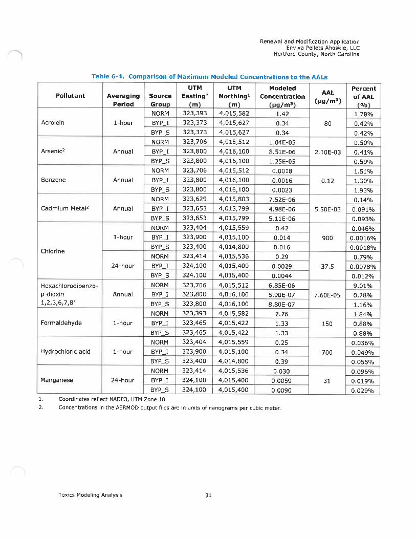
Renewal and Modification ApplicationEnviva Pellets Ahoskie, LLC
Hertford County, North Carolina
Pollutant
Table 6-4. Comparison of Maximum
UTMEasting*
Acrolein
Arsenic2
Benzene
Cadmiur' Metal2
Chlorine
Formaldehyde
Manganese
Averaging
Period
1-hour
Annual
Annual
Annual
1-hour
24-hour
Hexachlorodibenzo-
p-dioxin Annual1, 2, 3, 6, 7, 82
1-hour
Hydrochloric acid 1-hour
24-hour
1. Coordinates reflect NAD83, UTM
Source
Grou
NORM
BYP_I
BYP_S
NORM
BYP_I
BYP_S
NORM
BYP_I
BYP_S
NORM
BYP_I
BYP_S
NORM
BYP_I
BYP_S
NORM
BYP_I
BYP_S
NORM
BYP_I
BYP_S
NORM
BYP_I
BYP_S
NORM
BYP_I
BYP_S
NORM
BYP_I
BYP_S
Zone 18.
323, 393
323, 373323, 373323, 706
323, 800
323, 800323, 706
323,800
323, 800
323, 629
323, 653
323, 653
323, 404323, 900
323, 400
323, 414
324, 100
324, 100
323, 706
323, 800
323, 800
323, 393
323, 465
323, 465323, 404
323,900
323, 400
323, 414
324, 100
324, 100
Modeled Concentrations to the
UTM ModeledNorthing1 Concentration
m /m3
4,015,582 1.424, 015,627 0. 344,015,627 0. 344,015,512 1. 04E-05
4, 016, 100 8. 51E-064, 016, 100 1. 25E-05
4, 015, 512 0. 0018
4, 016, 100 0. 0016
4, 016, 100 0. 0023
4, 015,803 7. 52E-06
4,015,799 4. 98E-06
4, 015, 799 5. 11E-064,015,559 0.424, 015, 100 0. 014
4, 014, 800 0. 016
4, 015, 536 0. 29
4,015,400 0. 0029
4, 015, 400 0. 0044
4, 015, 512 6. 85E-06
4, 016, 100 5. 90E-07
4, 016, 100 8. 80E-07
4, 015, 582 2. 764, 015,422 1. 334, 015,422 1. 334, 015,559 0. 254,015, 100 0. 34
4,014,800 0. 39
4,015,536 0. 0304, 015, 400 0. 0059
4, 015, 400 0. 0090
AALs
AAL
(pg/m3)
80
2. 10E-03
0. 12
5. 50E-03
900
37.5
7. 60E-05
150
700
31
Percent
ofAAL%
1. 78%
0. 42%
0. 42%
0. 50%0. 41%
0. 59%1. 51%
1. 30%
1.93%
0. 14%
0. 091%
0. 093%
0. 046%
0. 0016%
0. 0018%
0. 79%
0. 0078%
0. 012%
9. 01%
0. 78%
1. 16%1. 84%
0.88%
0. 88%
0. 036%
0. 049%
0. 055%0. 096%
0. 019%
0. 029%
2. Concentrations in the AERMOD output files are in units of nanograms per cubic meter
Toxics Modeling Analysis 31

APPENDIX AAREA MAP

/^ N
Hotit SwatnPs', '
*,
^-^.'a»0
". '^-. t'fltf
'13 -'? i; ^e
I .ff..^'
z
V.'Swa^t,
Uthwrn&)!«»
// /.^» ^ ^-
de . / ^'^
liUhimnSdlu
1
!s'^ g*VMIW«ltS»""p
^
'*.'>.°v
Enviva Pellets Ahoskie, LLC
\) \
,n W^"^
»»
<>
^.<-
1\
,.«»X(im»1'
\
K
^ \ ).̂ __ - -- ̂ ~ --
» . _ --- -"'- <-'3-'' ~~ ~ - -
..f^^
\
Powellsvllle
^>°"
Kilometers
RAMB LL
DRAFTED BY: ARJ
Area MapEnviva Pellets Ahoskie, LLC
Ahoskie, Hertford County, North CarolinaDATE: 4/7/2020
FIGURE
1
'ROJECT: 1690016258

APPENDIX BPROCESS FLOW DIAGRAM

Appendix B - Process Flow DiaoramEnviva Pellets Ahoskie. LLC - Hertford Cour Quench
Duct
Four Green WoodHammermills
(ES-GHM-1 throughES-GHM-4)
Oryer WESP(CD-WESP)
Dryer KTO(CD-RTO)
Burners i fl DryerLineKTOStack
Green Wood gFibers/Chips
Dried WoodFlbers/Chips
DryerCydone
Heat to DryerSystem Ducts
Double DuctBurners
(IES-DDB-1,IES-DDB-2)
Natural Gas
ips
Note; £m!ssiamfrwn die »/HammefmUh wiilyo to cither;DJtwdfysrfwiioc^WESP.
' <rnd HTO:2) Divctly toffwwii tfna WESP
. witlftTO. -ar3) a combfmtfon o/ the two
Baghouse(CD-DHM-FF3)
Bag houses!(CD-DHM-FF1,;; CD-DHM-FF2)
Dust Control System(ES-DCS)
Dried Wood Handling(ES-DWH)
Conveyor Underside Dust Aspiration
7 Dry Hammermills(ES-DHM-1 through :<
ES-DHM-7) ; ;Screen
(Trucks)Pre-Chipped
Wood
(Trucks)Bartt/Fuel
Chips
._Sreen.. We.od..CiilBS_
Green WoodStorage Piles(ES-GWHS)
Green WoodHandling
(ES-GWHS)
Bark FuelStorage Piles(ES-GWHS)
Finished ProductHandling andLoadout Stack
Bark/!Fuel :
Chlps^
Bark Scrwner
6ark Hng[IES-BARKI
! GreenWood
! Fibers/I Chips
rrrucks)Dry
Shavings
Dry ShavingMaterial
Handling a ndStorage
(IES-DRYSHAVE)
Dry ShavingsHammermill(ES-DSHM)
> Cyclone
HighPressureBlouver
BarkHopper(IBS BH|
Finished Product !Handling Baghouse
(CD-FPH-RF) ;
J Dryer(ES-ORYER)
Furnace
Green Wood FuelStorage Bin(IES-GWF8)
Furnace Bypass(ES-FURNACEBYP)
FurnaceBypassStack
Fine Pellet Material
Baghouse(CD-FB-BV)
Fines Bin(ES-FB)
To Grade (forreintroductioninto process)
Pellet Loadout(ES-PL-1, ES-PL-2)
(Trucks)Finished Product
Finished Wood Truclc Loadout Bin «vith12 Pellet Bottoms
(ES-TLB)
Finished Wood Finished ProductHandling(ES-FPH)
Pellet Screener
Process Stream
Air Stream
Process Unit (ExisUng/New, Modified, or Renamed)
Air Pollution Control Device (Existing/New, Modified, or Renamed)
Stack (Existing/New or Renamed)
Finished Wood Pellet Product
Emergency Generator 1,350 bhp(IES-EG)
Quench Duct
Cyclones/Multi do nes
(CD-CLR-Clthrough C4)
6 Pellet Coolers
(ES-CLR-1 throughES-CLR-6) Wood Pellets
Pellet PressSystem
(Pellet Mills)
Back-up Power toPlant Operations
DieselFuel
Diesel Fuel Storage Tanks(IES-TK-1 through IES-TK-4)
(Trucks)PowderAdditive
Baghouse(CD-ADD-BF)
Additive Handlingand Storage(IES-ADD)
Fire WaterPump, 300 bhp
(IES-FWP)Back-up Power toFire Water Pump
Mobile Equipment
Note: Additive is cufrwtly received in 2,000 ;& supersacksand emptfed into a hopper. This application proposes toconstruct on adilstwesito{IES'ADD)andbaghouse fCDAODBF) ntowtiB aiMitiiv material la bdt to tieifellwfsd to the p;ont by trudc. Configuration shownrepresents worst cose emissions. RAMB LL

APPENDIX CPOTENTIAL EMISSIONS CALCULATIONS
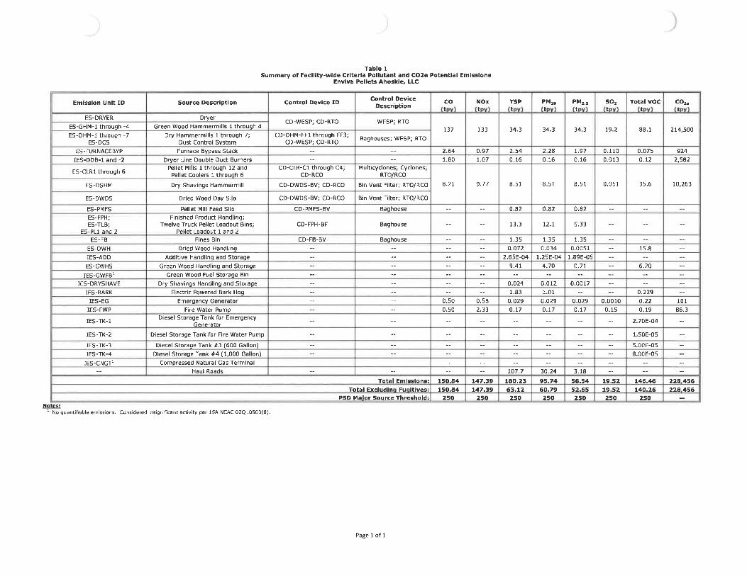
Table ISummary of Facility-wide Criteria Pollutant and C02e Potential Emissions
Envlva Pellets Ahoskle, LLC
Emission Unit ID
ES-DRYERES-GHM-1 through -4ES-DHM-1 through -7
ES-DCSES-FURNACEBYP
IES-DDB-1 and -2
ES-CLR1 through 6
ES-DSHM
E5-DWDS
ES-PMFSES-FPH;ES-TLB;
ES-PL1 and 2ES-FB
ES-DWH
IES-ADDES-GWHS
IES-GWFB1IES-DRYSHAVE
IES-BARKIES-EG
IES-FWP
IES-TK-1
IES-TK-2
IES-TK-3
IES-TK-4
IES-CNGT1
Source Description
Dryer
Green Wood Hammermills 1 through 4
Dry Hammermllls 1 through 7;Dust Control System
Furnace Bypass Stack
Dryer Line Double Duct BurnersPellet Mills 1 through 12 and
Pellet Coolers 1 throu h G
Dry Shavings Hammermill
Dried Wood Day Silo
Pellet Mill Feed SiloFinished Product Handling;
Twelve Truck Pellet Loadout Bins;Pellet Loadout 1 and 2
Fines Bin
Dried Wood Handling
Additive Handling and Storage
Green Wood Handling and Storage
Green Wood Fuel Storage Bin
Dry Shavings Handling and Storage
Electric Powered Bark Hog
Emergency Generator
Fire Water PumpDiesel Storage Tank for Emergency
Generator
Diesel Storage Tank for Fire Water Pump
Diesel Storage Tank #3 (600 Gallon)
Diesel Storage Tank #4 (1, 000 Gallon)
Compressed Natural Gas Terminal
Haul Roads
Control Device ID
CD-WESP; CD-RTO
CD-DHM-FF1 through FF3;CD-WESP; CD-RTO
CD-CLR-C1 through C4;CD-RCO
Control Device
Description
WESP; RTO
Baghouses; WESP; RTO
Multicyclones; Cyclones;RTO/RCO
cot
137
2. 641. 80
NOxt
133
0. 971. 07
TSPt
34.3
2. 540. 16
PMlDt
34.3
2. 280. 16
PM,.5t
34.3
1. 970. 16
so,t
19.2
0. 1100.013
Total VOCt
88.1
0. 0750. 12
co,.t
214,50
9242, 582
CD-DWDS-BV; CD-RCO
CD-DWDS-BV; CD-RCO
CD-PMFS-BV
CD-FPH-BF
CD-FB-BV
Bin Vent Filter; RTO/RCO
Bin Vent Filter; RTO/RCO
Baghouse
Baghouse
Baghouse
8. 21 9. 77 8. 51
0. 82
13.3
8. 51
0. 82
12.1
8, 51
0. 82
5. 33
0.051 35.6 10,263
Total Emissions:
Total Excludin Fu itives:PSD Ma'or Source Threshold:
0. 500. 50
150.84150.84
250
0. 582. 33
147.39147.39
250
0. 072
2. 65E-049.41
0. 0241. 83
0. 0290. 17
107.7180.2363. 12250
0. 034
1. 25E-044. 70
0. 0121. 01
0.0290. 17
30.2495.7460.79250
1. 89E-050. 71
0. 0017
0. 0290. 17
3. 1856.5452.65250
0. 00100. 15
19.5219.52250
15.8
6.20
0. 2290.220. 19
2. 70E-04
1. 50E-05
5. 00E-058.00E-05
146.46140.26
250
10186.3
228 456228 456
ND quantifiable emissions. Considered insignificant activity per ISA NCAC 02Q .0503(8).
Page 1 of 1

Table 2Summary of Facility-wide HAP Potential Emitsions
En»lva Pellets Ahoskie, LLC
Description
Acetaldeh deAcroleinFormaldeh deMethano;PhenolPro ionaldeh deAceto hen oneAmmoniaAntimon & corn oundsArsenic &. corn ouncfsBenzeneBenro a reneBer Ilium1 3-ButadieneCadmiumCarbon tetrachforideChlorineChlorobenzeneChloroformChromium VIChromium-Other corn aundsCobalt corn oundsDichlorobenzeneDichloroethane 1 2-Dichloro ro ane 1 2-Dinitro henol 2 4-Dl 2-eth Ihex I hthalate6th I benzeneHexachlorodfbenzo-; -dloxlnHexaneH drochloricacidLead and lead cam oundsMan anese & corn oundsMercurMeth I bromideMeth I chlorideMeth I eth I ketoneMeth lene chlorideNa hthaleneNickelNitro henol 4-Pentachloro henolPerchlaroeth lenePhos. horus metal ellow or whitePol chlorinated bi hen IsPol c die Or ante HatterSelenium corn oundsSt reneTetrachlorodibenzo- -dlaxin 237TolueneTrichloroethane 1 1 1-
richloroeth leneTrichlorofluoromethane
rtchloro henol 246-Vin I chlorideX lene
Maximum
NC TAP MAP
Y
YYNYN
NY
NYY
YY
YYYY
YYYN
NY
YN
NYN
YY
Y
Y
YY
KN
YN
NYNYYHY
NN
Y8- Y
YY
YY
NYY
Total MAPMaximum
1 Individual MAP
Y
YY
YYY
YN
YYY
YY
YY
YY
YY
YY
YY
YY
YY
Y
NY
YY
YYYY
NY
YY
YYYYY
YY
YY
YY
YN
YYY
Emissions tI Individual MAPEmissions tTotal TAP t
CD-RTOt
5. 25E-011.77E+003.65E+002.07E+001.S8E-019.S1E+OD1.23E-075. 46E-013.03E-048.79E-041.62E-01l.OOE-044.43E-05
3. 4SE-041.73E-03S. 07E-011.27E-031.07E-033. 73E-046.72E-042.64E-042. 05E-041. 11E-031. 27E-036. 91E-OG1.80E-061. 19E-036. 14E-043. 07E-013. 66E-011. 93E-036. 1SE-021.79E-045. 76E-048.83E-042. 07E-041. 11E-023. 83E-031.62E-034. 22E-061. 96E-061. 46E-031. 04E-033. 13E-075. 86E-031. 12E-047. 29E-023. 30E-103. 59E-021. 19E-D31. 15E-031. 57E-038.45E-076.91 E-D49. 60E-04
19.4Pro ionaldeh de
9.518.30
ES-FUIINACE8VP-1t
3.66E-031. 7GE-021.94E-02
2. 25E-042. 69E-041.41E-08
3.48E-059. 70E-051.B5E-021. 15E-054. 85E-06
1. 81E-051.98E-043. 48E-031. 45E-041.23E-041.54E-057. 71E-052. 86E-05
1.28E-041. 45E-G47. 93E-072. 07E-071.37E-047. 05E-06
8.37E-022. 12E-047. 05E-031. 54E-056. 61E-051.01E-042. 3BE-U61. 28E-034. 28E-041.45E-044. 85E-072. 25E-071.67E-041. 19E-043. 59E-085. 50E-041. 23E-058.37E-033. 79E-114. 05E-031. 37E-041. 32E-041. 81E-049. 70E-087. 93E-051. 10E-04
0. 17H drochloric add
0.0840.17
IES-DDB-1
and-2t
3. 26E-D73. 86E-071. 61E-03
6. 87E-D2
4. 29E-064. 51E-OS2. 58E-082. S8E-07
2. 36E-05
3. 01E-05
1. 80E-062. 58E-05
3. 86E-02
1. 07E-058. 16E-06S. 58E-06
1.3IE-054. 51E-05
1.50E-055. 15E-07
7. 30E-05
0. 041Hexane0.0390.11
CD-RCOt
9. 39E-018. 26E-019. 59E-012. 99E-013. 63E-011. 76E-01
2. 72E-01
1. 70E-051. 79E-041. 02E-071.02E-06
9. 35E-05
1. 19E-04
7. 14E.061.02E-04
1.S3E-01
4. 25E-053. 23E-052. 21E OS
5. 19E-051. 79E-04
5. 94E-052. D4E-G6
2. 89E-04
3.72Formaldeh de
0. 963. 51
ES-DWHt
1. 33E-01
1. 19E-012.44 E-B1
3. 91E-02
0.54Methanol
0.240. 25
[ES-EGt
4. 70E-045. 67E-057. 23E-04
5. 71E 041. 15E-07
2. 39E-05
1. 03E-04
2. 51E-04
1. 75E-040.0024
Formaldeh de7.23E-04
0. 0023
IES-FWPt
4. 03E-044. 86E-05G. 20E-04
4. 90E-049. 87E.08
2. 05E-05
8. 82E-05
2. 15E-04
1.50E-040.0020
Formaldeh de6.20E-04
0. 0019
IES-BARKt
4. 57E-02
0.046Methanol
0.0460
Pro
Totalt
1.60E+BO2. 61E+OB4. 75E+002. S6E+005. 52E-019. 73E+001. 37E-078.B6E-013. 38E-049. 97E-041. 81E-011. 12E-045. 04E-054. 45E-054. 80E-041. 93E-036. 10E-011.41E-031.20E-035. 38E-047. 49E-043. 01E-043. 32E-041. 24E-031.41E-037. 70E-062. DIE-061.33E-036. 21E-044. 99E-014. 50E-012. 19E-036. 86E-022. 22E-046. 42E-049. 84E-D42. 31E-041. 21E-024. 32E-031. 99E-034. 71E-D62. 18E-D61. 63E-031. 16E-D33. 49E-076. 67E-031. 26E-048. 13E-023. 68E-1D4. 08E-021. 33E-031. 28E-031. 75E-039. 42E-077. 70E-041. 39E-03
23.9ionaldeh de
9.7312.3
MajorSource?
NoNoNoNoNoNoNoNoNoNoNaNoNoNoNoNoNoNoNoNoNoNoNoNoNoNoNoNaNoNaNoNoNoNoNoNoNoNoNoNoHoNoNoNoNoNoNoNoNoNoNoNoNoNoNoNoNo
NoNo
Page 2 of 24
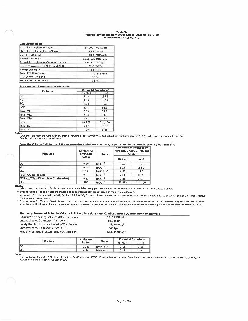
Calculation Basis
Annual Throu h ut of D er
Max. Hourl Throu h ut of Dr er
Burner Heat In ut
Annual Heat In ut
Annual Throu h ut of GHMs and DHMs
Hourl Throu h utofGHMs and DHMs
Annual 0 eratlon
otal RTO Heat InputRTO Control Efficiency
WESP Control Efficienc
Total Potential Emissions at RTO Stack
Pollutant
Table 3aPotential Emissions from Dryer Line RTO Stack (CD-RTO)
Enviva Pellets Ahoskie, LLC
550000 ODT ear62. 8 ODT hr
175. 3 MMBtu hr
1 535 628 MMBtu r550000 ODT r
62. 8 ODT hr
8 760 hr r40 MMBtU hr95 %95 %
Potential Emissions*Ib hr
CO 31.3NOx 30.3SO; 4. 38VOC 20.1otal PM 7. 83
otal PMu 7. 83otal PMss 7. 83
C0;e 48, 973Otal HAP 4. 42
. TAP 1. 90Notes:
1' Total emissions from the furnace/dryer, green hammermills, dry hammenDetailed calculations are provided below.
137.2132.719.288.134.3
34.334.3
214, 50019. 368. 31
lills, and natural gas combustion by the RTO (includes injection gas and burner fuel).
Potential Criteria Pollutant and Greenhouse Gas Emissions - Furnace D er Green Hammermills and Dry HammermillsPotential Emissions from
Pollutant
coNO,so;otal VOC as Propane
PM/PMio/PM;.5 (Filterable + Condensable)co,
ControlledEmission
Factor
0. 500. 48
0. 0250. 320. 12780
Units
lb/ODT;Ib/ODT2Ib/MMBtu3
lb/ODT;Ib/ODT'iboor'
Furnace/Dryer, GHMs, andDHMs1
(Ib/hr)
31.230.14. 3820.17. 83
48, 973
(tpy)
136.6132.019.288.134.3
214, 500Notes:
* Exhaust from the dr/er is routed to twin cyclones for material recovery purposes then to a WESP and RTO for control of VOC, HAP, and particulates.
2- Emission factor based on process information and an appropriate contingency based on engineering judgement.3- No emission factor is provided in AP-42, Section 10. 6. 2 for SO, for rotary dryers. Envlva has conservatively calculated SO; emissions based on AP-42, Section 1, 6 - Wood Residue
Combustion in Boilers, 09/03.
4- Emission factor for CO; from AP-42, Section 10, 6, 1 for rotary dryer with RTO control device. Enviva has conservatively calculated the CO; emissions using the hardwood emissionfactor because the dryer at the Ahoskie plant will use a combination of hardwood and softwood and the hardwood emission factor is greater than the softwood emission factor.
Thermal! Generated Potential Criteria Pollutant Emissions from Combustion of VOC from Dry HammermillsMaximum high heating value of VOC constituents 0.018 MMBtu/lb
Uncontrolled VOC emissions from DHMs 84. 1 Ib/hr
Hourly Heat Input of uncontrolled VOC emissions 1. 56 MMBtu/hr
Uncontrolled VOC emissions from DHMs 368 tpy
Annual Heat input of uncontrolled VOC emissions 13, 631 MMBtu/yr
Pollutant
coNOx
Notes:
EmissionFactor
0. 0820. 10
Units
Ib/MMBtu1Ib MMBtu1
Potential Emissions
(Ib/hr) t0. 13 0. 56
0. 15 0. 67
'. Emission factors from AP-42, Section 1. 4 - Natural Gas Combustion, 07/98. Emission factors converted from Ib/MMscf to Ib/MMBtu based on assumed heating value of 1, 020Btu/scf for natural gas per AP-42 Section 1.4.
Page 3 of 24

Table 3a
Potential Emissions from Dryer Line RTO Stack (CD-RTO)Enviva Pellets Ahoskie, LLC
Potential MAP Emissions
Pollutant
AcetaldehydeAcrolein
FormaldehydeMethanolPhenol
PropionaldehydeAcetophenone
Antimony & CompoundsArsenic &. CompoundsBenzene
Benzo(a)pyreneBerylliumCadmium
Carbon tetrachloride
Chlorine
Chlorobenzene
Chloroform
Chromium VI
Chromium-Other compoundsCobalt compoundsDlchloroethane, 1, 2-
Dichloropropane, 1, 2-Dinitrophenol, 2,4-
Di(2-ethylhexyl)phthalateEthyl benzeneHexachlorodibenzo-p-dioxinHydrochloric acidLead and Lead compounds
Manganese & compoundsMercuryMethyl bromideMethyl chlorideMethyl ethyl ketoneMethylene chlorideNaphthaleneNickel
Nitrophenol, 4-Pentachlorophenol
PerchloroethylenePhosphorus Metal, Yellow or WhitePolychlorinated biphenylsPolycyclic Organic MatterSelenium compoundsStyreneTetrachlorodibenzo-p-dioxin, 2/3, 7, 8-
oluene
NC TAP
iiii.inim.iirMii.inMiii
Emission
Factor
1. 91E-036. 42E-031. 33E-027. 52E-036. 84E-04
3.46E-023. 20E-097. 90E-06
2. 20E-054. 20E-032. 60E-061. 10E-064. 10E-064. 50E-057. 90E-043. 30E-052. 80E-053. 50E-061. 75E-056. 50E-062. 90E-053. 30E-05
1. 80E-07
4. 70E-08
3. 10E-051.60E-051. 33E-034. 80E-051. 60E-033. 50E-061. 50E-05
2. 30E-055.40E-062. 90E-049. 70E-053. 30E-051. 10E-075. 10E-083. 80E-052. 70E-058. 15E-091. 25E-042. BOE-061. 90E-038. 60E-129. 20E-043. 10E-05
3. 00E-054. 10E-052. 20E-081. 80E-052. 50E-05
Units
Ib/ODTIb/ODTIb/ODTIb/ODTIb/ODTIb/ODT
Ib/MMBtuIb/MMBtuIb/MMBtUIb/MMBtuIb/MMBtu
Ib/MMBtuIb/MMBtuIb/MMBtuIb/MMBtuIb/MMBtuIb/MMBtuIb/MMBtu
Ib/MMBtuIb/MMBtuIb/MMBtuIb/MMBtuIb/MMBtuIb/MMBtu
Ib/MMBtuIb/MMBtu
Ib/ODTIb/MMBtuIb/MMBtu
Ib/MMBtu
Ib/MMBtUIb/MMBtU
Ib/MMBtuIb/MMBtuIb/MMBtuIb/MMBtuIb/MMBtuIb/MMBtuIb/MMBtu
Ib/MMBtuIb/MMBtuIb/MMBtuIb/MMBtu
Ib/MMBtUIb/MMBtuIb/MMBtuIb/MMBtu
Ib/MMBtUIb/MMBtuIb/MMBtuIb/MMBtuIb/MMBtu
Footnote
1
1
1
1
1
1
2,32,4
2,4
2,32,32,42,42,32
2,32,32,42,42,4
2,3
2,32,32,32,32,31,52,42,42,42,32,32,32,32,32,42,32,32,32,42,32,32,42,32,32,32,32,32,32,32,32,3
Potential En
Ib/hr)
0. 120. 400. 830. 47
0. 0432. 17
2. 80E-08
6. 92E-051. 93E-043. 68E-022. 28E-059. 64E-063. 59E-053. 94E-041. 38E-012. 89E-042. 45E-043. 07E-051. 53E-045. 70E-Q52. 54E-04
2. B9E-041. 58E-064. 12E-Q7
2. 72E-041. 40E-048. 36E-024. 21E-04
1. 40E-02
3. 07E-05
1. 31E-042. 02E-04
4. 73E-052. 54E-038. 50E-042. 89E-049. 64E-074. 47E-073. 33E-042. 37E-Q47. 14E-Q8
1. 09E-03
2. 45E-051. 67E-02
7. 54E-11
8. 06E-032. 72E-042. 63E-043. 59E-041. 93E-071. 58E-042. 19E-Q4
4. 351.70
iissions
(tpy)
0. 531. 773. 652. 070. 199. 51
1. 23E-07
3.03E-048.45E-041.61E-019.98E-054. 22E-051. 57E-041. 73E-036. 07E-011. 27E-031. 07E-031. 34E-04
6. 72E-042. 50E-041. 11E-031. 27E-036. 91E-061. 80E-061. 19E-036. 14E-043. 66E-011.84E-036. 14E-02
1. 34E-04
5. 76E-048. 83E-042. 07E-041. 11E-023.72E-031. 27E-034. 22E-061. 96E-061.46E-031. 04E-03
3. 13E-074. 79E-031. 07E-04
7. 29E-023. 30E-103. 53E-021. 19E-031. 15E-031. 57E-038.45E-076.91E-049. 60E-04
19.07.46
Total HAP Emissions:Total TAP Emissions:
Notes:1- Emission factor based on process information and an appropriate contingency based on engineering judgement.
2 Emission factors for wood combustion in a stoker boiler from AP-42 Section 1. 6 - Wood Residue Combustion in Boilers, 09/03.
3 A control efficiency of 95% for the RTOs is applied to all organic HAP for those emission factors that are not derived from Enviva stack test data. This is the expected controlefficiency of the RTO.
4- A 95% control efficiency for the wet electrostatic precipitator (WESP) is applied to all metal MAP based on expected control efficiency far the WESP.s- The WESP will employ a caustic solution in its operation in which hydrochloric acid will have high water solubility, This caustic solution will neutralize the acid and effectively control
it by 90%, per conversation on October 18, 2011 with Steven A. Jaasund, P. E. of Lundberg Associates, a manufacturer of WESPs.
6- The emissions from the Green Hammermills and Dry Hammermills will be routed through the Dryer Line WESP and RTO.
''. Chromium VI is a subset of chromium compounds, which is accounted for separately as a HAP. As such. Chromium VI is on!y calculated as a TAP
Page 4 of 24

Table 3aPotential Emissions from Dryer Line RTO Stack (CD-RTO)
Enviva Pellets Ahoskie, LLC
Potential HAP Emissions - RTO Burners
Pollutant
RTO Natural Gas Combustion
2-Methylnaphthalene3-Methylchloranthrene
7, 12-Dlmethylbenz(a)anthraceneAcenaphtheneAcenaphthyleneAmmonia
Anthracene
Arsenic & CompoundsBenz(a)anthraceneBenzene
Benzo(a)pyreneBenzo(b)fluorantheneBenzo(g/h/i)perylene
Benzo(k)fluoranthene
Beryllium
Cadmium
Chromium VI
ChryseneCobalt compoundsDibenzo(a,h)anthraceneDichloro benzene
Fluoranthene
Fluorene
Hexane
Indeno(l, 2, 3-cd)pyrene
Lead and Lead compounds
Manganese & compoundsMercuryNaphthaleneNickelPhenanthrene
PyreneSelenium CompoundsToluene
AP
Y
Y
Y
Y
Y
N
Y
Y
Y
Y
Y
Y
Y
Y
Y
Y
Y
Y
Y
Y
Y
Y
Y
Y
Y
Y
Y
Y
Y
Y
Y
Y
Y
Y
NC TAP
N
N
N
N
N
Y
N
Y
N
Y
Y
N
N
N
Y
Y
N
N
N
N
Y
N
N
Y
N
N
y
Y
N
Y
N
N
N
Y
Emission
Factor*
2. 40E-051. 80E-061. 60E-051. 80E-061. 80E-06
3.22. 40E-Q62. 00E-Q4
1. 80E-062. 10E-Q31. 20E-Q61. 80E-061. 20E-061.80E-061. 20E-051. 10E-03
1. 40E-03
1. 80E-068.40E-051. 20E-061. 20E-033. 00E-062.80E-06
1. 801.80E-065.00E-043.80E-042.60E-046. 10E-042. 10E-031. 70E-055. QOE-062.40E-053.40E-03
Units
Ib/MMscfIb/MMscfIb/MMscfIb/MMscfIb/MMscfIb/MMscf
Ib/MMscfIb/MMscf
Ib/MMscfIb/MMscfIb/MMscfIb/MMscfIb/MMscf
Ib/MMscfIb/MMscfIb/MMscfIb/MMscfIb/MMscf
Ib/MMscfIb/MMscfIb/MMscf
Ib/MMscfIb/MMscfIb/MMscf
Ib/MMscf
Ib/MMscf
Ib/MMscfIb/MMscfIb/MMscfIb/MMscfIb/MMscf
Ib/MMscfIb/MMscf
Ib/MMscfTotal MAP Emissions
Total TAP Emissions
Potential Emi
Ib/hr
9. 34E-07
7. 01E-086. 23E-07
7. 01E-08
7. 01E-081. 25E-019. 34E-087. 78E-067.01E-088. 17E-054.67E-087. 01E-08
4. 67E-08
7.01E-084.67E-074. 28E-OS5.45E-057. 01E-083. 27E-064.67E-084.67E-051. 17E-071. 09E.077. 01E-02
7. 01E-08
1.95E-051.48E-051.01E-052. 37E-058. 17E-056.62E-071.95E-079. 34E-071. 32E-040.0710.20
t
4. 09E-06
3. 07E-072. 73E-063. 07E-07
3. 07E-075. 46E-014. 09E-073. 41E-053. 07E-073. 58E-042. 05E-073. 07E-07
2. 05E-07
3. 07E-072. 05E-061. 88E-042. 39E-043. 07E-071. 43E-052. 05E-072. 05E-045. 11E-074. 77E-073. 07E-013. 07E-07
8. 52E-056.48E-054. 43E-05
1. 04E-04
3. 58E-04
2. 90E-068. 52E-074. 09E-065. 80E-04
0.310.85
Notes:
Emission factors for natural gas combustion are from NCDAQ Natural Gas Combustion Spreadsheet and AP-42, Fifth Edition, Volume 1, Chapter 1. 4 - Natural Gas Combustion,07/98. The emission factor for ammonia is cited in the NCDAQ spreadsheet as being sourced from the USEPA's WebFIRE database. Acetaldehyde, acrolein, and formaldehyde arenot included in this table because emissions of these pollutants resulting from RTO fuel combustion are already refiected in the Ib/ODT emission factors,
Abbreviations:
CH4 - methane
CO - carbon monoxide
CO; - carbon dioxide
C0;e - carbon dioxide equivalentGHM - Green Hammermill
MAP - hazardous air pollutant
hr - hour
kg - kilogram
Ib - pound
Mgal - thousand gallons
MMBtu - Million British thermal units
MMscf - Million standard cubic feet
NOx- nitrogen oxides
N^O - nitrous oxide
ODT - oven dried short tons
PM - particulate matter
PMio - particulate matter with an aerodynamic diameter less than 10 microns
PM2. 5 - particulate matter with an aerodynamic diameter of 2. 5 microns or less
RTO - regenerative thermal oxidizer
SOz- sulfur dioxide
tpy - tons per year
VOC - volatile organic compound
WESP - wet electrostatic precipitator
yr- year
EPA. AP-42, Section 1.4 - Natural Gas Comtiustion. 07/98.
EPA. AP-42, Section 1.6 - Wood Residue Combustion In Boilers, 09/03.
Page 5 of 24

Calculation Basis
Hourly Heat Input CapacityAnnual Heat Input CapacityHours of 0 oration
Table 3b
Potential Emissions from Furnace Bypass (Cold Start-up)Enviva Pellets Ahoskie, LLC
26, 3 MMBtu/hr
1, 315 MMBtu/yr50 hr/ r
Potential Criteria Pollutant and Greenhouse Gas Emissions - Furnace B ass Cold Start-u
co
NOxso;voc
otal PM
otal PMio
otal PM;.s
co,CH,N;0C0;e
PollutantEmission
Factor
0. 60
0. 22
0. 025
0. 017
0. 58
0. 52
0. 45
93.8
0. 0072
0. 0036
Units
Ib/MMBtu'Ib/MMBtu'lb/MMBtu1Ib/MMBtu'Ib/MMBtu'Ib/MMBtu'lb/MMBtu1k /MMBtu2k /MMBtu2k /MMBtu2
Potential Emissions
Ib hr15.8
5. 78
0. 66
0. 45
15.2
13.6
11.8
5, 438
0. 42
0. 21
5,510
t
0. 39
0. 140. 016
0. 011
0. 38
0. 34
0. 29
136
0. 010
0. 0052
138
CO, NO,, SO,, PM, PMin, PM, s, and VOC emission rates based on AP-42, Section 1. 6 - Wood Residue Combustion in Boilers. 09/03 For bark/bark and wet wood-flredboilers. PM, PMio, and PM^. s factors equal to the sum of the filterable and condensable factors from Table 1. 6-1. VOC emission factor excludes formaldehyde.Emission Factors for biomass combustion From Table C-l and C-2 of 40 CFR Part 98 and Global Warming Potentials from Table A-l.
Page 6 of 24

Table 3b
Potential Emissions from Furnace Bypass (Cold Start-up)Envlva Pellets Ahoskie, LLC
r -
Pollutant
Acetaldehydecrolein
Formaldehyde
Phenol
Propionaldehyde
Acetophenone
Antimony & Compounds
Arsenic & Compounds
Benzene
Benzo(a)pyrene
Beryllium
Cadmium
Carbon tetrachloride
Chlorine
Chlorobenzene
Chloroform
Chromium VI
Chromium-Other compounds
Cobalt corn pounds
Dichloroethane, 1, 2-
Dichloropropsne, 1, 2-
Dinitraphenol, 2, 4-
Di(2-ethylhexyl)phthalate
Ethyl benzene
Hexachlorodibenzo-p-dioxin
Hydrochloric acid
Lead and Lead compounds
Manganese & compounds
Mercury
Methyl bromide
Methyl chlorideMethyl ethyl ketone
Methylene chloride
Naphthalene
Nickel
Nitrophenol, 4-
Pentachlorophenol
Perchloroethylene
Phosphorus Metal, Yellow or white
Polychlorinated biphenylsPolycydic Organic MatterSelenium compounds
Styrene
etrachlorodibenzo-p-dioxin, 2, 3, 7, 8-
oluene
richloroethane, 1, 1, 1-
Trichloroethylene
richlorofluoromethane
richlorophenol, 2, 4, 6-
Vinyl chlorideX lene
HAP
Y
Y
Y
Y
Y
Y
Y
Y
Y
Y
Y
Y
Y
Y
Y
Y
2
Y
Y
Y
Y
Y
Y
Y
N
Y
Y
Y
Y
Y
Y
N
Y
Y
Y
Y
Y
Y
Y
Y
Y
Y
Y
Y
Y
Y
Y
N
Y
Y
Y
NC TAP
Y
Y
Y
Y
N
N
N
Y
Y
Y
Y
Y
Y
Y
Y
Y
Y
N
N
Y
N
N
Y
N
f
Y
N
Y
Y
N
N
Y
Y
N
Y
N
Y
Y
N
Y
N
N
Y
Y
Y
Y
Y
Y
N
Y
Y
Emission
Factor'
8. 30E-04
4. 00E-03
4. 40E-03
5. 10E-05
6. 10E-05
3. 20E-09
7. 90E-06
2. 20E-05
4. 20E-03
2. 60E-06
1. 10E-06
4. 1DE-G6
4. SOE-05
7. 90E-04
3. 30E-05
2. 80E-05
3. 50E-06
1. 75E-05
6. 50E-06
2. 90E-05
3. 30E-05
1. 806-07
4. 70E-08
3. 10E-05
1. 60E-06
1. 90E-02
4. 80E-05
1. 60E-03
3. 50E-06
1. 50E-05
2. 30E-05
5. 40E-06
2. 90E-04
9. 70E-05
3. 30E-05
1. 10E-07
5. 10E-08
3.8DE-05
2. 70E-05
8. 15E-09
1. 25E-04
2. 80E-06
1. 90E-03
S. 60E-12
9. 20E-04
3. 10E-05
3. 00E-05
4. 10E-05
2. 20E-08
1. 80E-05
2. 50E-05
Units
Ib/MMBtu
Ib/MMBtu
Ib/MMBtu
Ib/MMBtu
Ib/MMBtu
Ib/MMBtu
Ib/MMBtu
Ib/MMBtu
Ib/MMBtu
Ib/MMBtu
Ib/MMBtu
Ib/MMBtu
Ib/MMBtu
Ib/MMBtu
Ib/MMBtu
Ib/MMBtu
Ib/MMBtu
Ib/MMBtu
Ib/MMBtu
Ib/MMBtu
Ib/MMBtu
Ib/MMBtu
Ib/MMBtu
Ib/MMBtu
Ib/MMBtu
Ib/MMBtu
Ib/MMBtu
Ib/MMBtu
Ib/MMBtu
Ib/MMBtu
Ib/MMBtu
Ib/MMBtu
Ib/MMBtu
Ib/MMBtu
Ib/MMBtu
Ib/MMBtu
Ib/MMBtu
Ib/MMBtu
Ib/MMBtu
Ib/MMBtu
Ib/MMBtu
Ib/MMBtu
Ib/MMBtu
Ib/NMBtu
Ib/MMBtu
Ib/MMBtu
Ib/MMBtu
Ib/MMBtu
Ib/MMBtu
Ib/MMBtu
Ib/MMBtu
Total MAP Emissions:
Total TAP Emissions: I
Potential Emission;
(Ib/hr) t2. 18E-02
1. 05E-G1
1. 1GE-01
1. 34E-03
1. 60E-03
8. 41E-08
2. 08E-04
5. 73E-04
1. 10E-01
6. 84E-05
2. B9E-05
1. 08E-04
1. 18E-03
2. 08E-02
8. 68E-04
7. 36E-04
9. 20E-OS
4.60E-04
1. 71E-04
7. 63E-04
8.68E-04
4. 73E-06
1. 24E-06
8. 15E-04
4. 21E-05
5. 00E-01
1. 26E-03
4. 21E-02
9. 20E-05
3. 94E-04
6. 05E-04
1. 42E-04
7. 63E-03
2. 55E-038. 68E-04
2. 89E-06
1. 34E-06
9. 99E-04
7. 10E-04
2. 14E-07
3. 28E-03
7. 36E-05
5. 00E-02
2. 26E-10
2. 42E-02
8. 15E-04
7. 89E-04
1. 08E-03
5. 78E-07
4. 73E-04
6. 57E-04
1. 02
1.01
5. 46E-01
2. 63E-03
2. 89E-03
3. 35E-05
4. 01E-05
2. 10E-09
5. 19E-06
1. 45E-05
2. 76E-03
1.71E-06
7. 23E-B7
2. 70E-06
2. 96E-05
5. 19E-04
2. 17E-05
1. 64E-05
2. 30E-06
1. 15E-05
4. 27E-06
1. 91E-05
2. 17E-05
1. 18E-07
3. 09E-08
2. 04E-05
1. 05E-06
1. 25E-02
3. 16E-05
1. 05E-03
2. 30E-06
9. 86E-06
1. 51E-05
3. 55E-OS
1. 91E-04
6. 38E-05
2. 17E-05
7. 23E-08
3. 35E-08
2. 50E-05
1. 77E-05
5. 35E-09
8. 20E-05
I. S4E-06
1. 25E-03
5. 65E-12
6. 05E-04
2. 04E-05
1. 97E-05
2. 70E-05
1. 45E-08
1. 18E-05
1. 64E-05
0. 025
0. 025
Notes:1 Emission factors for wood combustion in a stoker boiler from AP-42, Section 1z Chromium VI is a subset of chromium compounds, which is accounted for sep;
. 6 - Wood Residue Combustion in Boili
irately as a MAP. As such. Chromiumlere, 09/03.VI is only calculated as a TAP.
Abbreviations:CHa - methane
CO - carbon monoxide
CO, - carbon dioxide
COze - carbon dioxide equivalentHAP - hazardous air pollutanthr - hour
kg - kilogramib - poundMMBtu - Million British thermal units
NC - North CarolinaNOx- nitrogen oxides
N;0 - nitrous oxideODT - oven dried short tonsPM - particulate matterPMio - particulate matter with an aerodynamic diameter less than 10 micronsPM; s - particulate matter with an aerodynamic diameter of 2.5 microns or lessSO; - sulfur dioxideTAP - Toxic Air Pollutant
tpy - tons per yearVOC - volatile organic compoundyr - year
EPA. AP-42, Section 1.6 - Wood Residue Combustion in Boilers, 09/03.
Page 7 of 24
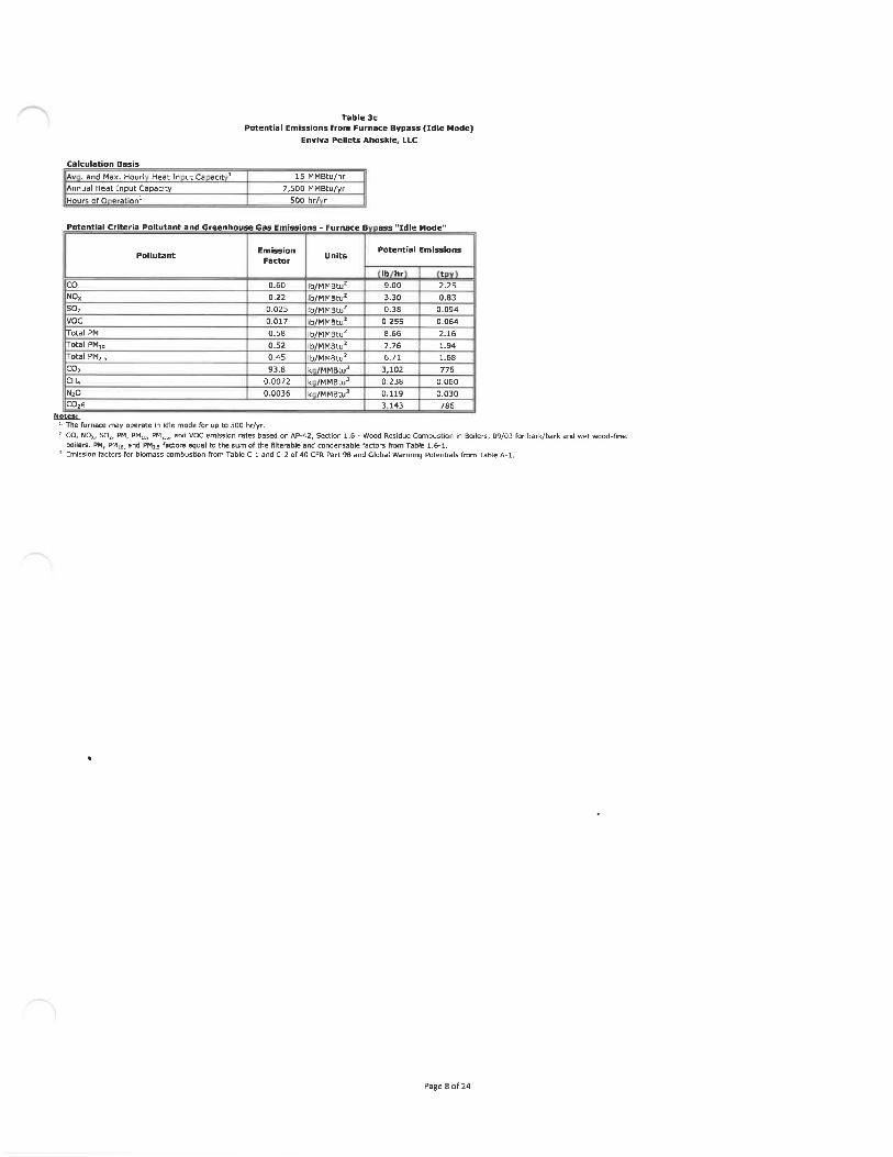
Calculation Basis
Av . and Max. Hour! Heat In ut Ca acit
Annual Heat Input Capacity
Hours of 0 eration
Table 3c
Potential Emissions from Furnace Bypass (Idle Mode)Envlva Pellets Ahoskle, LLC
15 MMBtu/hr
7,500 MMBtu/yr500 hr/ r
Potential Criteria Pollutant and Greenhouse Gas Emissions - Furnace B ass "Idle Mode"
EmissionFactor
0.60
0. 22
0. 025
0. 017
0. 58
0. 52
0. 45
93.8
0. 0072
0. 0036
Units
Ib/MMBtu'lb/MMBtu;Ib/MMBtu'Ib/MMBtu2Ib/MMBtu2Ib/MMBtu2Ib/MMBtu2k /MMBtu3k /MMBtu3k /MMBtu3
.ntlal Emission'
Ib hr
9. 00
3. 30
0. 38
0. 255
8. 66
7.766. 71
3, 102
0. 238
0. 119
3 143
t
2. 25
0. 83
0. 094
0. 064
2. 16
1. 94
1. 68
775
0, 060
0. 030
786
co
NO,so,voc
Total PM
otal PMin
otal PM, 5
co;CH4N;0
C0;eNotes:
1 The furnace may operate in idle mode for up to 500 hr/yr.! CO, N0», SO,, PM, PHu, PMi. s, and voc emission rates based on AP-42, Section 1. 6 - Wood Residue Combustion In Boilers, 09/03 for bark/bark and wet wood-nred
boilers. PM, PMio. and PM;5 factors equal to the sum of the filterable and condensable factors from Table 1.6-1.3 Emission factors for biomass combustion from Table C-l and C-2 of 40 CFR Part 98 and Global Warming Potentials from Table A-l.
Page 8 of 24

Potential HAP Emissions - Furnace B
Table 3c
Potential Emissions from Furnace Bypass (Idle Mode)
Enviva Pellets Ahoskie, LLC
ass "Idle Mode"
Pollutant
Acetaldehyde
Acroiein
Formaldehyde
Phenol
Propionaldehyde
Acetophenone
Antimony & Compounds
Arsenic & CompoundsBenzene
Benzo(a)pyrene
Beryllium
Cadmium
Carbon tetrachloride
Chlorine
Chlorobenzene
Chloroform
Chromiunn VI
Chromium-Other compounds
Cobalt compounds
Dichloroethane, 1,2-
Dichloropropane, 1, 2-
Dinitrophenol, 2,4-Di(2-ethylhexyl)phthalate
Ethyl benzene
Hexachlorodibenzo-p-dioxin
Hydrochloric acid
Lead and Lead compounds
Manganese &. compounds
Mercury
Methyl bromide
Methyl chloride
Methyl ethyl ketone
Methylene chloride
Naphthalene
Nickel
Nitrophenol, 4-Pentachlorophenol
Perchloroethylene
Phosphorus Metal, Yellow or White
Polychlorinated biphenyls
Polycyclic Organic Matter
Selenium compounds
Styrene
etrschlorodibenzo-p-dioxin, 2, 3, 7, 8-
oluene
richloroethane, 1, 1, 1-
richloroethylene
richlorofluoromethane
richlorophenol, 2, 4,6-
Vinyl chloride
X lene
Notes:Emission factors For wood combustion in a stoker
MAP
Y
Y
Y
Y
Y
Y
Y
Y
Y
Y
Y
Y
Y
Y
Y
Y
2
Y
Y
Y
Y
Y
Y
Y
N
Y
Y
Y
Y
Y
Y
N
Y
Y
Y
Y
Y
Y
Y
Y
Y
Y
Y
Y
Y
Y
Y
N
Y
Y
Y
NC TAP
Y
Y
Y
Y
N
N
N
Y
Y
Y
Y
Y
Y
Y
Y
Y
Y
N
N
Y
N
N
Y
N
Y
Y
N
Y
Y
N
N
Y
Y
N
Y
N
Y
Y
N
Y
N
N
Y
Y
Y
Y
Y
Y
N
Y
Y
Emission
Factor'
8. 30E-04
4. 00E-03
4.40 E-03
5. 10E-05
6. 10E-05
3. 20E-09
7. 90E-06
2. 20E-05
4. 20E-03
2. 60E-06
1. 106-06
4. 10E-06
4. 50E-05
7. 90E-04
3. 30E-05
2. 80E-05
3. 50E-06
1. 75E-05
6. 50E-06
2.90 E-05
3. 30E-05
1. 8GE-07
4. 70E-08
3. 10E-05
1. 60E-06
1. 90E. 02
4. BOE-05
1. 60E-03
3. 50E-D6
1. 50E-05
2. 30E-05
5. 40E-06
2. 90E-04
9. 70E-05
3. 30E-05
1. 10E-07
5. 10E-08
3. SOE-05
2. 70E-05
8. 15E-09
1. 25E-04
2. 80E-06
1. 90E-03
8. 60E-12
9.20E-04
3. 10E-05
3. 00E-OS
4. 10E-05
2. 20E-08
1. 80E-05
2. 50E-05
Units
Ib/MMBtu
Ib/MMBtu
Ib/MMBtu
Ib/MMBtu
Ib/MMBtu
Ib/MMBtu
Ib/MMBtu
Ib/MMBtu
Ib/MMBtu
Ib/MMBtu
Ib/MMBtu
Ib/MMBtu
Ih/MMBtu
Ib/MMBtu
Ib/MMBtu
Ib/MMBtu
Ib/HMBtu
Ib/MMBtu
Ib/MMBtu
Ib/MMBtu
Ib/MMBtu
Ib/MMBtu
Ib/MMBtu
Ib/MMBtu
Ib/MMBtu
Ib/MMBtu
Ib/MMBtu
Ib/MMBtu
. b/MMBtu
Ib/MMBtu
Ib/MMBtu
Ib/MMBtu
Ib/MMBtu
Ib/MMBtu
Ib/MMBtu
Ib/MMBtu
Ib/MMBtu
Ib/MMBtu
Ib/MMBtu
Ib/MMBtu
Ib/MMBtu
Ib/MMBtu
Ib/MMBtu
Ib/MMBtu
Ib/MMBtu
Ib/MMBtu
Ib/MMBtu
Ib/MMBtu
Ib/MMBtu
Ib/MMBtu
Ib/MMBtu
Total MAP Emissions:
Total TAP Emissions:
boiler from AP-42, Section 1.6 - Wood Residue Combustion in Boilers,
Potential E
Ib/hr1. 25E-02
6. 00E-02
6. 60E-02
7. 65E-04
9. 15E-04
4. 8DE-OB
1. 19E-04
3. 30E-04
6. 30E-02
3, 906-05
1. 65E-05
6. 15E-05
6.75E-04
1. 19E-02
4. 95E-04
4. 20E-04
5. 25E-05
2. 63E-04
9. 75E-05
4. 35E-04
4. 95E-04
2. 70E-06
7. 05E-07
4. 65E-04
2. 40E-05
2. 85E-01
7. 20E-04
2. 40E-02
5. 25E-05
2. 25E-04
3. 45E-04
8. 10E-05
4. 35E-B3
1.46E-03
4. 95E-04
1. G5E-06
7. 65E-07
5. 70E-04
4. 05E-04
1. 22E-07
1. 87E-03
4. 20E-05
2. 85E-02
1. 29E-10
1. 38E-02
4. 65E-04
4. 50E-046. 15E-04
3. 30E-07
2. 70E-04
3. 75E-04
0. 58
0. 58
09/03.
missions
t
3. 11E-03
1. 50E-02
1. 6SE-02
1. 91E-04
2. 29E-04
1. 20E-D8
2. 96E-05
8. 25E-05
1. 58E-02
9. 75E-06
4. 13E-06
1. 54E-051. 69E-04
2. 96E-03
1. 24E-04
1. 05E-04
1. 31E-05
6. 56E-05
2.44E-05
1. 09E-04
1. 24E-04
6. 75E-07
1. 76E-07
1. 16E-04
6. aOE-06
7. 13E-02
1. 80E-04
6. 00E-03
1. 31E-05
5. 63E-05
8. 63E-05
2. 03E-05
1. 09E-03
3.64E-04
1.24E-04
4. 13E-07
1. 91E-07
1. 43E-04
I.OIE-04
3. 05E-08
4.6BE-04
1. 05E-OS
7. 13E-03
3. 236-11
3. 45E-03
1. 16E-04
1. 13E-04
1. 54E-04
8. 25E-08
6. 75E-05
9. 38E-05
0. 145
0. 144
z- Chromium VI is a subset of chromium compounds, which is accounted for separately as a MAP. As such. Chromium VI is only calculated as a TAP
Abbreviations:CH4 - methane
CO - carbon monoxide
CO; - carbon dioxideC0;e - carbon dioxide equivalentMAP - hazardous air pollutanthr - hour
kg - kilogramIb - poundMMBtu - Million British thermal units
NC - North CarolinaNOx - nitrogen oxides
Reference:EPA. AP-42, Section 1. 6 - Wood Residue Combustion in Boilers. 09/03.
N;0 - nitrous oxide
ODT - oven dried short tons
PM - particulate matter
PMiD- particulate nnatter with an aerodynamic diameter less than 10 micronsPM3 s - particulate matter with an aerodynamic diameter of 2. 5 microns or lessSO; - sulfur dioxideTAP-Toxic Air Pollutant
tpy - tons per yearVOC - volatile organic compoundyr - year
Page 9 of 24

Duct Burner Inputs
Duct Burner RatingNumber of Duct Burners
Annual 0 eration
Table 4
Potential Emissions from Double Duct Burners (IES-DDB-1 and -2)Enviva Pellets Ahoskie, LLC
2. 5 MMBtu/hr2
8, 760 hr/yr
Potential Criteria Pollutant Emissions - Natural Gas Combustion
Pollutant
co
NOxso;vocPM/PMio/PMs. s CondensablePM/PMio/PMz. s Filterable
co,CH4N;OZ
0,e
Emission
Factor
84.050.00. 605. 505. 701. 90
120, 0002. 300. 64
Units
Ib/MMscfIb/MMscfIb/MMscfIb/MMscfIb/MMscfIb/MMscf
Total
Ib/MMscfIb/MMscfIb/MMscf
Footnote
1
2
1
1
1
1
PM/PMio/PM,.s1
1
1,23
Potential
Hourly
0.410. 25
0. 00290.0270. 028
0. 00930. 037
5880. 01130. 0031
589
Emissions
Annual
1. 801.07
0. 0130. 1180. 1220.041
0. 162, 5760. 0490.0142, 582
Emission factors for natural gas combustion from AP-42 Section 1. 4 - Natural Gas Combustion, 07/98. Natural gas heating value of1, 020 Btu/scf assumed per AP-42,Emission factors for NOx and N;0 assume burners are low-NOx burners,C0., e emissions were estimated based on the Global Warming Potentials listed in Table A-l of 40 CFR 98 Subpart A.
Page 10 of 24

Table 4Potential Emissions from Double Duct Burners (IES-DDB-1 and -2)
Enviva Pellets Ahoskie, LLCPotential MAP and TAP Emissions
Pollutant
Natural Gas Combustion
2-Methylnaphthalene3-Methylchloranthrene7, 12-Dimethylbenz(a)anthracene
Acenaphthene
Acenaphthylene
AcetaldehydeAcrolein
Ammonia
Anthracene
Arsenic & Compounds
Benz(a)anthraceneBenzene
Benzo(a)pyreneBenzo(b)fluoranthene
Benzo(g,h, i)peryleneBenzo(k)fluorantheneBerylliumCadmium
Chromium VI
Chrysene
Cobalt compoundsDibenzo(a,h)anthraceneDichlorobenzene
Fluoranthene
Fluorene
FormaldehydeHexane
Indeno(l,2, 3-cd)pyreneLead and Lead compounds
Manganese & compoundsMercury
NaphthaleneNickelPhenanthrene
Pyrene
Selenium Compoundsoluene
AP
Y
Y
Y
Y
Y
Y
Y
N
Y
Y
Y
Y
Y
Y
Y
Y
Y
Y
Y
Y
Y
Y
Y
Y
Y
Y
Y
Y
Y
Y
Y
Y
Y
Y
Y
Y
Y
NC TAP
N
N
N
N
N
Y
Y
Y
N
Y
N
Y
Y
N
N
N
Y
Y
N
N
N
N
Y
N
N
Y
Y
N
N
Y
Y
N
Y
N
N
N
Y
Emission
Factor*
2. 40E-051. 80E-061. 60E-051. 80E-061.80E-061. 52E-051. 80E-OS
3. 20E+002. 40E-062. 00E-04l. BOE-062. 10E-031. 20E-061. 80E-061.20E-061. 80E-061. 20E-051. 10E-031.40E-031.80E-068. 40E-051. 20E-061. 20E-033. 00E-062. 80E-06
0.0751. 80
1. 80E-065. 00E-043. 80E-042.60E-046. 10E-042. 10E-031. 70E-055. 00E-062. 40E-053. 40E-03
Units
Ib/MMscfIb/MMscfIb/MMscfIb/MMscfIb/MMscfIb/MMscfIb/MMscfIb/MMscfIb/MMscfIb/MMscfIb/MMscfIb/MMscfIb/MMscfIb/MMscfIb/MMscfIb/MMscfIb/MMscfIb/MMscfIb/MMscfIb/MMscfIb/MMscfIb/MMscfIb/MMscfIb/MMscfIb/MMscfIb/MMscfIb/MMscfIb/MMscfIb/MMscfIb/MMscfIb/MMscfIb/MMscfIb/MMscfIb/MMsrfIb/MMscfIb/MMscfIb/MMscf
Total HAP Emissions:
Total TAP Emissions:
(Ib/hr)
1. 18E-078.82E-097. 84E-088. 82E-098. 82E-097. 45E-088. 82E-081. 57E-021. 18E-089. 80E-078. 82E-091. 03E-055. 88E-098. 82E-09S. 88E-098. 82E-095. 88E-085. 39E-066. 86E-Q68. 82E-094. 12E-075. 88E-095. 88E-061.47E-081. 37E-083. 68E-048. 82E-038. 82E-092. 45E-061. 86E-061. 27E-062. 99E-061. 03E-058. 33E-082. 45E-081. 18E-071. 67E-05
0.00930. 025
(tpy)
5. 15E-073. 86E-083. 44E-073. 86E-083. 86E-083. 26E-073.86E-076. 87E-025. 15E-084. 29E-063. 86E-084. 51E-052. 58E-083. 86E-082. 58E-083. 86E-082. 58E-072. 36E-053. 01E-053. 86E-081. 80E-062. 58E-082. 58E-056. 44E-086. 01E-081. 61E-033. 86E-023. 86E-081. 07E-058. 16E-065. 58E-061. 31E-054. 51E-053. 65E-071. 07E-075. 15E-077. 30E-05
0.0410. 11
Notes:. Emission factors for natural gas combustion are from NCDAQ Natural Gas Combustion Spreadsheet and AP-42, Fifth Edition, Volume 1, Chapter 1. 4 - Natural Gas
Combustion, 07/98. The emission factors for acetaldehyde, acroleln, and ammonia are cited in the NCDAQ spreadsheet as being sourced from the USEPA's WebFIREdatabase.
Ahfcinaviations:
CAS - chemical abstract service
CHd - methane
CO - carbon monoxide
C02 - carbon dioxide
C0;e - carbon dioxide equivalent
MAP - hazardous air pollutant
hr - hour
kg - kilogramIb - pound
MMBtu - Million British thermal units
NOx - nitrogen oxides
NaO - nitrous oxide
ODT - oven dried short tons
PM - particulate matter
PMia - particulate matter with an aerodynamic diameter less than 10 microns
PM,.5 - particulate matter with an aerodynamic diameter of 2.5 microns or less
SO; - sulfur dioxide
TAP - toxic air pollutant
tpy - tons per year
VOC - volatile organic compound
yr - year
(eferences:
EPA. AP-42, Section 1. 4 - Natural Gas Combustion, 07/98.
Page 11 of 24

Table SPellet Mill/Pellet Cooler, Dry Shavings Hammermill, and Dried Wood Day Silo Potential Emissions at Outlet of RTO/RCO
Stack (CD-RCO)Enviva Pellets Ahoskie, LLC
Calculation Basis
PM/PC Hourly Throughput
PM/PC Annual Throughput
DSHM Hourly Throughput
DSHM Annual Throughput
Hours of Operation
RTO/RCO Burner Rating
RTO/RCO Control Effidenc
74.8 ODT/hr
630,000 ODT/yr12 ODT/hr
100,000 ODT/yr8,760 hr/yr
20 MMBtu/hr95.0 %
Total Potential Emissions at RTO RCO StackPotential Emissions1
Pollutant
coNOxso;vocTotal PMTotal PMioTotal PM;.s
C0,e,Tol.3l HAD
Ib/hr
1. 882. 24
0. 0128. 452. 012. 012. 01
2, 3430. 880. 83
t
8. 219.8
0. 05135.68.58.58.5
10, 2633. 723. 51
by the RTO/RCO (injection gas and burner fuel).
Potential PM VOC and MAP Emissions from Pellet Mills and Pellet Coolers
Pollutant
Acetaldehyde
Acrolein
Formaldehyde
MethanolPhenolPro ionaldeh de
HAP
Y
Y
Y
Y
Y
Y
. Condensable)
NC TAP
Y
Y
Y
N
Y
N
Total VOCPM/PMio/PM;.; (Filterable
Notes:' Emission factor based on process information and an appropriate contingency based on engini
on ro e
Emission
F r1(Ib/ODT)2. 92E-032. 52E-033. 00E-038.83E-041.09E-035. 16E-04
Total HAP EmissionsTotal TAP Emissions
0. 100. 017
Potential Emissions
(Ib/hr)0. 220. 190. 22
0. 0660. 0820. 0390.820. 717. 531. 28
(tPV)0. 920. 790. 950. 280. 340. 163. 44
3.0031.75. 39
iring judgement.
Page 12 of 24

Table 5Pellet Mill/Pellet Cooler, Dry Shavings Hammermill, and Dried Wood Day Silo Potential Emissions at Outlet of RTO/RCO
Stack (CD-RCO)
Enviva Pellets Ahoskie, LLC
Pollutant MAP NC TAP
Potential PM VOC and MAP Emissions from Or Shavin s Hammermillon ro e
Emission
F r'
Acetaldehyde Y YY Y
Formaldehyde Y YY NY Y
ionaldeh de Y N
Total HAP
Total TAP EmissionsTotal VOCPM/PMio/PM;.5 (Filterable + Condensable)
Notes:* Emission factor based on process information and an appropriate contingency based on engineering judgement,
Potential Emissions
Acetaldehyde
Acrolein
Formaldehyde
Methanol
Phenol
Pro ionaldeh de
Y
Y
Y
Y
Y
Y
Y
Y
Y
N
Y
N
Ib/ODT
3. 80E-046. 40E-04
2. 70E-04
4. 13E-043. 96E-Q42. 64E-04
Total HAP EmissionsTotal TAP Emissions
0. 0670. 033
(Ib/hr
0.00460. 00770. 00320. 00500. 00480. 00320.0280.0200. 800.40
* y0. 0190. 0320. 0140. 021
0.01980. 0130.12
0.0843. 351. 66
Potential Emissions
t
0. 820. 820. 82
Potential Particulate Emissions from Dried Wood Da Silo Bin Vent CD-DWDS-BVExhaust Flow Exit Grain
Pollutant Rate1 Loadln 2'3cfm r cf Ib hr
+ Condensable 0. 187 ;
u (Filterable + Condensable) 2, 186 I 0. 01 I 0. 187
2. 5 (Filterable + Condensable) 0. 187 I
Notes:'. Inlet flow rate (cfm) was obtained fronn previous permit application. The exit flowrate was conservatively assumed to be the same as the iniet flowrate.2 Pollutant loading based on data from other Enviva facilities.3 No spedation data is available for PMin/PM;. ;. Therefore, it is conservatively assumed to be equal to total PM.
Thermally Generated Potential Criteria Pollutant Emissions from Combustion of VOC from Dry Shavings Hammermill, PelletMills and Pellet CoolersMaximum high heating value ofVOC constituents 0. 018 MMBtu/lb
Uncontrolled VOC emissions 167 Ib/hr
Heat input of uncontrolled VOC emissions 3. 08 MMBtu/hr
Uncontrolled VOC emissions 702 tons/yrHeat input of uncontrolled VOC emissions 25, 958 MMBtu/yr
Pollutant
coNOx
Emission
Factor1
0.0820. 10
Units
Ib/MMBtUIb/MMBtu
Potential I
Ib hr0. 250. 30
Emission;
t
1. 071. 27
Potential Criteria Pollutant and Greenhouse Gas Emissions - RTO RCO Burners
PollutantEmission
Factor1
RTO/RCO Burners - Natural Gas Combustion
CO 0. 082NOx 0. 10
5. 88E-045. 39E-031. 86E-035. 59E-03
N;0C0;e
1182. 25E-032. 16E-03
Units
Ib/MMBtuIb/MMBtu
Potential Emissions
Ib hr t
1. 631. 94
0. 0120. 11
0. 0370. 110. 15
2, 3290. 0450. 0432, 343
7. 148. 50
0.0510. 470. 160. 480. 65
10,2030. 200. 19
10,263Notes:
1 Emission factors from AP-42, Section 1.4 - Natural Gas Combustion, 07/98. Emission factors converted from Ib/MMscfto Ib/MMBtu basedon assumed heating value of 1, 020 Btu/scf for natural gas per AP-42 Section 1. 4.
Page 13 of 24

Table 5Pellet Mill/Pellet Cooler, Dry Shavings Hammermill, and Dried Wood Day Silo Potential Emissions at Outlet of RTO/RCO
Stack (CD-RCO)Envlva Pellets Ahoskie, LLC
Potential HAP Emissions - RTO/RCO Burners
Pollutant Hi
RTO/RCO Burners - Natural Gas Combustion
2-Methylnaphthalene
3-Methylchloranthrene
7, 12-Dlmethylbenz(a)anthracene
Acenaphthene
Acenaphthylene
Acrolein
Ammonia
Anthracene
Arsenic & Compounds
Benz(a)anthraceneBenzene
Senzo(a)pyrene
Benzo(b)fluoranthene
Benzo(g, h, l)perylene
Benzo(k)fluoranthene
Beryllium
Cadmium
Chromium VI
Chrysene
Cobalt compounds
Dlbenzo(a,h)anthracene
Dichlorobenzene
Fluoranthene
Fluorene
Hexane
Indeno(l, 2, 3-cd)pyrene
Lead and Lead compounds
Manganese & compounds
Mercury
Naphthalene
NickelPhenanthrene
Pyrene
Selenium Compounds
Toluene
AP
Y
Y
Y
Y
Y
Y
N
Y
Y
Y
Y
Y
Y
Y
Y
Y
Y
Y
Y
Y
Y
Y
Y
Y
Y
Y
Y
Y
Y
Y
Y
Y
Y
Y
Y
NC TAP
N
N
N
N
N
Y
Y
N
Y
N
Y
Y
N
N
N
Y
Y
N
N
N
N
Y
N
N
Y
N
N
Y
Y
N
Y
N
N
N
Y
Emission
Factor'
2.40E-051.80E-061. 60E-051.80E-061.80E-061.80E-05
3.22.40E-062. 00E-Q41. 80E-062. 10E-031. 20E-061. 80E-061. 20E-061. 80E-061. 20E-051. 10E-031. 40E-031. 80E-068.40E-051. 20E-061. 20E-033. 00E-062. 80E-06
1. 801. 80E-065. 00E-043. 8QE-042. 60E-046. 10E-042. 10E-031. 70E-055. 00E-062. 40E-053. 40E-03
Units
Ib/MMscfIb/MMscf
Ib/MMscfIb/MMscfIb/MMscfIb/MMscfIb/MMSCfIb/MMscfIb/MMscfIb/MMscf
Ib/MMscfIb/MMscfIb/MMSCfIb/MMscfIb/MMscfIb/MMscfIb/MMscf
Ib/MMscfIb/MMscfIb/MMscfIb/MMscf
Ib/MMscf
Ib/MMscfIb/MMscfIb/MMscfIb/MMscfIb/MMscfIb/MMscf
Ib/MMscf
Ib/MMscfIb/MMscfIb/MMSCf
Ib/MMscf
Ib/MMscfIb/MMscf
Total MAP Emissions:Total TAP Emissions:
(Ib/hr)
4. 66E-073.49E-083. 11E-073. 49E-Q83. 49E-083.49E-076. 21E-024. 66E-083. 88E-063. 49E-084. 08E-052. 33E-083. 49E-082. 33E-083. 49E-082. 33E-072. 14E-052. 72E-053.49E-081. 63E-062. 33E-082. 33E-055. 82E-085. 44E-083.49E-023.49E-089. 71E-067. 38E-065.05E-061. 18E-054. 08E-053. 30E-079. 71E-084. 66E-076. 60E-05
0.0350. 10
(tpy)
2.04E-061. 53E-071. 36E-061. 53E-071. 53E-071. 53E-062. 72E-012. 04E-071. 70E-051. 53E-071. 79E-041. 02E-071. 53E-071. 02E-071. 53E-071. 02E-069. 35E-051. 19E-041. 53E-077. 14E-06
1. 02E-071.02E-042. 55E-072. 38E-071. 53E-011. 53E-074. 25E-053. 23E-052. 21E-055. 19E-051. 79E-041.45E-064. 25E-072.04E-062. 89E-04
0. 150.43
Notes:
. Emission factors for natural gas combustion are from NCDAQ Natural Gas Combustion Spreadsheet and AP-42, Fifth Edition, Volume 1, Chapter 1. 4 - NaturalGas Combustion, 07/98. The emission factors for acrolein and ammonia are cited in the NCDAQ spreadsheet as being sourced from the USEPA's WebFIREdatabase. Formaldehyde and acetaldehyde are not included in this table because emissions af these pollutants resulting from RTO/RCO fuel combustion arealready reflected in the controlled fb/ODT emission factors.
A b b rev iatkins:
Btu - British thermal units
CH4 - methane
CO - carbon monoxide
CO; - carbon dioxide
C0;e - carbon dioxide equivalent
HAP - hazardous air pollutant
hr- hour
Ib - pound
MMBtu - Million British thermal units
NOx- nitrogen oxides
NzO - nitrous oxide
ODT - oven dried short tons
PM - particulate matter
PMio - particulate matter with an aerodynamic diameter less than 10 microns
PM2, s ~ particulate matter with an aerodynamic diameter of 2. 5 microns or less
RCO - regenerative catalytic oxidi?er
RTO - regenerative thermal oxidizer
scf - standard cubic feet
SO;- sulfur dioxide
TAP - Toxic Air Pollutant
tpy - tons per year
VOC - volatile organic compound
yr - year
References:EPA. AP-42, Section 1.4- Natural Gas Combustion, 07/9S.
Page 14 of 24

Table 6Potential Emissions from Bark Hog (IES-BARK)
Enviva Pellets Ahoskie, LLC
Calculation Basis
Annual ThroughputHourly ThroughputApproximate Moisture Content
91, 406 ODT/yr10.4 ODT/hr150%
Potential EmissionsPollutant
VOC as propane2PM3
PMio3Methanol
Emission Factor Hourly(Ib/hr)
0. 05
0.420. 230. 01
Annual
(tpy)0. 23
1. 831. 010. 05
5. 00E-03 Ib/ODT
2. 00E-02 Ib/ton1. 10E-02 Ib/ton
l. OOE-03 Ib/ODTNotes:
' Annual throughput calculated based on 100% of the estimated Annual Dryer Heat Input, assuming 4, 200 Btu/lb HHV(wet) and 50% Moisture. Maximum hourly throughput based on maximum fuel usage for the furnace.
2 Emission factor for VOC as propane is from AP-42, Section 10. 6. 3., Medium Density Fiberboard, 08/02, Table 7.3 Particulate matter emission factors from the EPA document titled AIRS Facility Subsystem Source Classification Codes
and Emission Factor Listing for Criteria Air Pollutants. Source Classification Code 3-07-008-01 (Log Debarking). All PMis assumed to be larger than 2. 5 microns.
4 Emission factor obtained from available emissions factors for chippers in AP-42 Section 10. 6. 3, Medium DensityFiberboard, 08/02, Table 7 and Section 10. 6. 4, Hardboard and Fiberboard, 10/02, Table 9.
References:
EPA. AP-42, Section 10.6. 3, Medium Density Fiberboard, 08/02.EPA. AP-42, Section 10, 6. 4, Hardboard and Fiberboard, 10/02.
EPA. AIRS Facility Subsystem Source Classification Codes and Emission Factor Listing for Criteria Air Pollutants. March1990.
Abbreviations:
hr - hour
Ib - poundODT - oven dried short tons
tpy - tons per yearVOC - volatile organic compoundyr - year
Page 15 of 24

Table 7
Potential Emissions from Dried Wood Handling (ES-DWH)Enviva Pellets Ahoskie, LLC
Calculation Basis
Hourly ThroughputAnnual Throu h utl
Potential VOC and HAP Pollutant Emissions
63 ODT/hr
550, 000 ODT/yr
Emission
Factor2
Potential Emissions
(Ib/ODT)
4. 32E-04
1. 42E-04
8. 88E-04
4. 84E-04
Total HAP Emissions
0. 057
Hourly
(Ib/hr)0. 027
0. 009
0. 056
0. 030
0.12
3. 61
Annual
(tpy)0. 119
0. 039
0. 24
0. 13
0.5415.8
Pollutant
Formaldehyde
Propionaldehyde
Methanol
Acetaldehyde
otal VOC (as propane)Notes:
1- Hourly and annual throughputs assumed to be equal to the dryer throughput.2- Emission factors based on process information and an appropriate contingency based on engineering
judgement.
Abbreviations:hr - hour
Ib - poundODT - oven dried short tons
tpy - tons per yearVOC - volatile organic compoundyr - year
Page 16 of 24

Table S
Potential PM Emissions from Baghouses/CyclonesEnviva Pellets Ahoskle, LLC
Emission Unit ID Source Description
ES-PMFS
ES-FB
Pellet Mill Feed Silo
Fines Bin
Control Device ID
CD-PMFS-BV
CD-FB-BV
Control Device
Description
One (1) baghouseOne (1) baghouse
ExhaustFlow Rate'
(cfm)2. 1B6
3, 600
Exit Grain
Loading2
(gr/cf)0.01
0. 01
AnnualOperation
(hours)
8, 760
8, 760
Particulate Speciation
PMio% of PM
100%
100%
PM,.s»A of PM
100%
100%
ES-FPH; Finished PrDduct Handling;
ES-TLB; Tnelue truck pellet loadout bins; CD-FPH-BF One (1) baghouse"''' 35, 5DO 0. 01 8, 760 91% 40%ES-PL1 and PL2 Pellet load-out 1 and 2
Notes:}- Far esisting sources, filter, vent, and cyclone inlet flaw rates [cfm) were obtained from previous permit application. The exit flowrate was conservatively assumed to be the same as the inlet flowrate.2- Pollutant loading based on previous permit applications,3- No speciation data is available far PMiu/PM^. s. Therefore, it is conservatively assumed to be equal to total PM.
4- Finished product handling PMio speciation based on AP-42 factors For wet wood combustion (Section 1.6) controlled by a mechanical separator. Since the partide size ofparticulate matter from a pellet cooler Is anticipated to be larger than flyash, this factor is believed to be a conservative indicator of speciation.
5 Finished product handling PM^.s speciation based on review of NCASI data for similar baghouses in the wood products industry,
HourlyIb hr
0. 1870. 31
3. 04
Annualt
0. 82
1. 35
13. 33
Potential Emissions
PM,,Hourly AnnualIb hr t
0. 187
PM,.sHourly Annual
0. 31
D. B2
1. 35
Ib hr
0. 187
0. 31
1.217
t
O. S2
1. 35
5.331
Abhrevlatluns:cf - cubic feet
cfm - cubic feet per minuteES - Emission Sources
IES - Insignificant Emission Sourcegr - grainhr - hour
Ib - poundPM - particulate matter
PMin . particulate matter with an aerodynamic diameter less than 10 micronsPM;.s - parti culate matter with an aerodynamic diameter of 2. 5 microns or lesstpy - tons per year
Page 17 of 24

Table 9
Potential Emissions from Material HandlingEn»iva Pellets Ahoskle, LLC
Transfer Activity1 ControlDescription
Enclosed
Enclosed
Enclosed
Reduction to 2 mphmean wind speed
Reduction to 2 mphmean wind speed
Reduction to 2 mphmean wind speed
Purchased Bark unloading via Truck TipperDrop Points via FEL/CDnveying from Bark Pile to
ES-GWHS D er Fur"":eGreen Wood Chips unloading via Truck TippersDrops Points via FEtyC onveying from Chip Pile to
Dryer
Dryer Di3charge to Outfeed Conveyor
ES-DWH Dryer Outfeed Conveyors to Silo Feed/Silo Bypass
Conveyor to Hammermill Surge Bin drop Into HMSurge Bin
IES-ADO Additire Handling and Storage -- 1 10%
IES-DRYSHAVE Drv sh"""SS ""l°"il"S "la Truck Tipper 1 14%Dry Shavings Drop from Storage to Conveyor 1 14%
stss;1 Emission factor calculation based on formula From AP-42, Section 13. 2.4 - Aggregate Hdndling and Storage Piles, Equation 1, (11/D6).
E= k (0. 0032) (U/5)"l<(H/2)"where: E = emission factor (Ib/ton)
k = particle size multiplier (dimensionless) for PM 0. 74
k = particle size multiplier (dimensionless) for PMio 0. 35
k = particle si;e multiplier (dimensionless) for PM;^ 0. 053
U = mean wind speed (mph) 6.3
U = mean wind speed (mph) for enclosed drops 2
M = material moisture content (%)
! Throughputs represent green weight of materials, calculated based on listed material moisture contents.
Numberof DropPoints
1
4
4
8
1
MaterialMoistureContent
(%)48%
48%
48%
48%
10%
PMEmission
Factor1
(Ib/ton)
3. 74E-05
3. 74E-05
3. 74E-QS
3. 74E-05
7. 5GE-05
PMl.Emi»ianFactor
(Ib/ton)
1. 77E-05
1. 77E-05
1.77E-05
1.77E-05
3. 58E-05
P"1SEmission
Factor1
(lb/t»n)
2. 68E-D6
2. 68E-06
2. 68E-D6
2. 6BE-D6
5. 41E-OG
Potential
Throughput3
(tph)
100
21
440
150
70
(tpy)
182,500
182,500
1. 100,000
1. 100,000
632. 500
Potential PM
Emissions
Hourly(Ib/hr)3. 74E-03
3. 14E-03
6. 58E-02
4. 48E-02
5. 27E-03
Annual
(tpy)3. 41E-03
1.36E-02
8. 22E-02
1.64E-01
2. 39E 02
Potential PMi,Emissions
Hourly(Ib/hr)1. 77E-03
1. 48E-03
3. 11E-02
2. 12E-02
2. 49E-03
Annual(tpy)
1.61E-03
6.45E-03
3. 89E 02
7. 78E-02
1. 13E-0:
Potential PMi.sEmissions
Hourly(Ib/hr)
2. 68E-04
2. 25E-04
4. 71E-03
3. 21E-03
Annual
(tpy)2.44E-04
9. 77E-04
5. 89E-03
1. 18E-02
7. 56E-05 3.58E-05 5. 41E-06
7. 56E-05 3. 58E-05 5. 41E-OG
3. 36E-04 1. 59E-04 2. 41E-05
2. 10E-04 9. 92E-05 1. 50E052. 10E-04 9. 92E-05 l. SOE-OS
70
632,500 5. 27E-03 2. 39E-02 2. 49E-03 1. 13E-02 3. 78E-04 1. 71E-03
632,500 5. 27E-03 2. 39E-02 2.49E-03 1. 13E-02 3. 78E-04 1. 71E-B3
25 1, 575 8.40E-D3 2.65E-04
5D 116, 279 1. 05E-02 1. 22E-02
20 116,279 4. 20E-03 1. 22E-02Total Emissions: 0.16 0.36
3. 97E-D3 1.25E-04 G.02E-04 1.89E-054.96E-03 5. 77E-03 7. 51E-04 8.73E041. 98E-03 5. 77E-03 3.00E-04 8. 73E-04
0.074 0.17 0.011 0.026
References:EP/ ]iles, 11/06.
Abbreviations:hr - hourIb- poundPM - particulste matterPMin- particulate matter with an aerodynamic diameter less than 10 micronsPM;. s - particulate matter with an aerodynamic diameter of 2, 5 microns or less
tpy - tons per yearyr - year
Page 18 of 24

Table 10
Potential Emissions from Storage Pile Wind Erosion (ES-GWHS)Enviva Pellets Ahoskie, LLC
Source Description
Green Wood Chip Storage Pile I
Green Wood Chip Storage Pile 2
Bark Storage Pile
Mixing Storage Pile
PM Emiission
Factor'
(Ib/day/acre)
6. 48
6. 48
6. 486. 48
(Ib/hr/ft
6. 2E-066. 2E-06
6. 2E-066. 2E-06
VOC Emission
Factor2
(;ba/cde7 <-/-/«')3. 603. 603. 603. 60
3. 4E-063. 4E-063. 4E-06
3. 4E-06
PileWidth
(ft)
300
200150
200
Pile PileLength Height
(ft) (ft)
350
400
40
150
ExposedSurfaceArea of
Pile'
Potential PMEmissions
Potential PMioEmissions
Potential PM 1.5Emissions
Potential VOC
Emissions
(as propane)
(ft2) (Ib/hr) (tpy) (Ib/hr) (tpy) (Ib/hr) (tpy) (Ib/hr) (tpy)
20
20
2D
20Toti
157,200124, 800
16, 320
38,446il Emissions:
0. 98
0. 770. 10
0. 238
2. 09
4. 27
3. 39
0. 44
1. 04
9. 15
0. 49
0. 39
0. 0510. 119
1. 04
2. 14
1. 700. 22
0. 5224. 57
0. 073
0. 0580. 008
0. 01790.157
0. 320
0. 2540. 033
0. 0783
0. 69
0. 66
0. 52
0. 0690. 1615
1.41
2. 892, 30
0. 300. 7076. 20
Notes:'. PM emission factor based on U. S, EPA Control of Open Fugitive Dust Sources, Research Triangle Park, North Carolina, EPA-450/3-88-008. September 1988, Page 4-17.
l-s-17[M^l^b/-^where; s, silt content of wood chips (%):
p, number of days with rainfall greater than 0. 01 inch:
f (time that wind exceeds 5. 36 m/s - 12 mph) (%):
PMio/TSP ratio;
PM;s/TSP ratio;
8, 4 s - silt content [%) for lumber sawmills (mean) from AP-42, Section 13. 2. 2 - Unpaved Roads, 11/06, Table 13. 2. 2-1
120 Based on AP-42, Section 13. 2. 2 - Unpaved Roads, 11/06, Figure 13. 2, 1-2,
9, 8 Based on meteorological data averaged for 2007-2011 for Northampton, NC.
PMi, is assumed to equal 50% of TSP based on U. S. EPA Control of Open Fugltre Dust Sources, Research Triangle Park, North Carolina, EPA-450/3-88-008. September1988.
PN;.., Is assumed to equal 7. 5 % of TSP U. S. EPA Background Document for Reulslons to Fine Fraction Ratios Used For AP-42 Fugltre Dust Emission Factors. November 2006.
z' VOC emission factor obtained from NCA5I Technical Bulletin No. 700, A Preliminary Investigation of Releases of Volatile Organic Compounds from Wood Residual Storage Piles For the calculation of fugitive VOC emissions from Dougfas Fir wood storage piles,Emission factors ranged from 1. 6 to 3. 6 )b C/acre-day. The maximum emission factor has conservatively been selected,
J The surface area for rectangular piles is calculated as [2*tH3<:L4-2*W*H+L*W] + 20% to onsider the sloping pile edges,
Emission factor converted from as carbon to as propane by multiplying by 1.22.
Abbreviations:
EPA - Environmental Protection Agencyft - feet
ft2 ~ square feetIb - poundmph - miles per hourNCASI - National Council for Air and Stream Improvement, Inc.NWS - National Weather Service
PM - particulate matterPMio- particulate matter with an aerodynamic diameter less than 10 micronsPM;. 5' particulate matter with an aerodynamic diameter of 2. 5 microns or less
tpy - tons per yearTSP - Total Suspended Particulateyr-yearVOC - volatile organic compound
References;EPA. AP-42, Section 13. 2. 2 - Unpaged Roads, 11/06.u. s. EPA, Control of Open Fugitive Dust Sources, Research Triangle Park, North Carolina, EPA-450/3-88-008. September 1988,U. S. EPA. Background Document for Revisions to Fine Fraction Ratios Used forAP-42 Fugitive Dust Emission Factors. November 2006,NCASI, Technical Bulletin No. 700, Preliminary Investigation of Releases of Volatile Organic Compounds from Wood Residual Storage Piles. October 1995.
Page 19 of 24
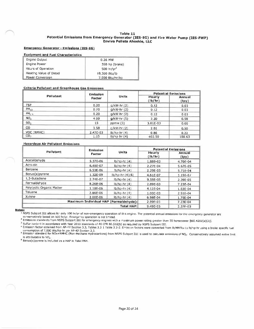
Table 11Potential Emissions from Emergency Generator (IES-EG) and Fire Water Pump (IES-FWP)
Enviva Pellets Ahoskie, LLC
Emer enc Generator - Emissions IES-EG
E ui ment and Fuel Characteristics
Engine Output 0. 26 MW
Engine Power 350 hp (brake)Hours of Operation 500 hr/yr1Heating Value of Diesel 19, 300 Btu/lbPower Conversion 7 000 Btu hr h
Criteria Pollutant and Greenhouse Gas Emissions
Pollutant
T5PPMioPM2.5NO,so;coVOCCNMHCco;
lazardous Air Pollutant
Pollutant
Acetaldehyde
Aero Iein
Benzene
Benzo(a)pyrene
1,3-Butadiene
Formaldehyde
Polycyclic Organic MatterToluene
X lene
Emission
Factor
0. 200. 200. 204. 00
15
3. 50
2.47E-031. 15
Emissions
Emission
Factor
5. 37E-06
6. 48E-07
6. 53E-061. 32E-09
2. 74E-07
8. 26E-061. 18E-062.86E-062. 00E-06
Maximum Individual HAP
Units
kW-hr 2
g/kW-hr (2)g/kW-hr (2)g/kW-hr (5)ppmw (3)
M/kW-hr 2
Ib/hp-hr (4Ib/hp-hr(4)
Units
Ib h -hr 4Ib h -hr 4
Ib h -hr 4Ib h -hr 4 6
Ib h -hr 4Ib h -hr 4
Ib h -hr 4
Ib h -hr 4Ib h -hr 4
(Formaldehyde):
Total HAP:
HourlyIb/hr
0. 120. 12
0. 122. 30
3. 81E-03
2. 010. 86
402. 50
PotentialHourlyIb/hr
1.88E-032. 27E-04
2. 29E-03
4. 61E-079. 58E-052. 89E-034. 12E-04
l. OOE-036. 98E-04
2. 89E-03
9. 49E-03
Annualt
0. 030. 030. 030. 580. 00
0. 500. 22
100. 63
Emissions
Annualt
4. 70E-04
5. 67E-Q5
5. 71E-041. 15E-072. 39E-057. 23E-04
1. 03E-04
2. 51E-041. 75E-04
7. 23E-042. 37E-03
Notes:
NSPS Subpart IIII allows for only 100 hr/yr of non-emergency operation of this engine. The potential annual emissions for the emergency generator areconservatively based on 500 hr/yr. Emergency operation is not limited.
2 Emissions standards from NSPS Subpart IIII for emergency engines with a maximum power rating greater than 50 horsepower [§60. 4202(a)(2)].3 Sulfur content in accordance with Year 2010 standards of 40 CFR 80.510(b) as required by NSPS Subpart IIII.4 Emission factor obtained from AP-42 Section 3. 3, Tables 3.3-1 Table 3. 3-2. Emission factors were converted from Ib/MMBtu to Ib/hp-hr using a brake-specific fuel
consumption of 7, 000 Btu/hp-hr per AP-42 Section 3. 3.
5 Emission standard for NOx+NMHC (Non-Methane Hydrocarbons) from NSPS Subpart IIII is used to calculate emissions of NQ(. Conservatively assumed entire limitis attributable to N0».
6 Benzo(a)pyrene is included as a HAP in Total PAH.
Page 20 of 24

Table 11Potential Emissions from Emergency Generator (IES-EG) and Fire Water Pump (IES-FWP)
Enviva Pellets Ahoskie, LLC
Firewater Pum Emissions IES-FWP
E ui ment and Fuel Characteristics
Engine Output 0. 22 MW
Engine Power 300 hpHours of Operation 500 hr/yr1Heating Value of Diesel 19, 300 Btu/lbPower Conversion 7 000 Btu hr h
Criteria Pollutant and Greenhouse Gas Emissions
Pollutant
TSPPMloPM2.5N 0^
SO,coVOC (NMHCco;
Hazardous Air Pollutant Emissions
Pollutant
Acetaldehyde
Acrolein
Benzene
Benzo(a)pyrene
1, 3-Butadiene
Formaldehyde
Polycyclic Organic Matter
Toluene
X leneMaximum
Emission
Factor
2. 20E-032. 20E-032. 20E-03
3. 10E-022. 05E-03
6. 68E-032.47E-03
1. 15
Fsctor
5. 37E-06
6. 48E-07
6. 53E-061. 32E-092. 74E-07
8. 26E-06
1. 18E-06
2. 86E-062. 00E-06
Individual HAP
Units
Ib h -hr 2Ib/hp-hr(2)Ib/hp-hr(2)Ib/hp-hr(2)Ib/hp-hr(2)
Ib/hu-hnZ
lb/h. i-hrf2Ib/hp-hr(2)
Units
Ib h -hr 2Ib h -hr 2
Ib h -hr 2Ib h -hr 2 3
Ib h -hr 2Ib h -hr 2
Ib h -hr 2
Ib h -hr 2Ib h -hr 2
(Formaldehyde):
Total HAP:
HourlyIb/hr
0. 660. 660. 669. 30
0. 62
2. 00
0. 74345
PotentialHourlyIb/hr
1. 61E-031. 94E-04
1. 96E-033. 95E-078. 21E-052.48E-033. 53E-04
8. 59E-045. 99E-04
2.48E-038.13E-03
Annual
t
0. 170. 17
0. 172. 330. 15
0. 500. 19
86.25
EmissionsAnnual
t
4. 03E-04
4.86E-054.9QE-049. 87E-082. 05E-05
6. 20E-048.82E-052. 15E-04
1. 50E-04
6. 20E-042.03E-03
Notes:1 NESHAP Subpart ZZZZ allows for only 100 hr/yr of non-emergency operation of this engine. The potential annual emissions for the fire water pump are
conservatively based on 500 hr/yr. Emergency operation is not limited.2 Emission factor obtained from AP-42 Section 3. 3, Tables 3. 3-1 Table 3. 3-2. MAP emission factors were converted from Ib/MMBtu to Ib/hp-hr using a brake-speciHc
fuel consumption of 7, 000 Btu/hp-hr per AP-42 Section 3. 3.3 Benzo(a)pyrene is included as a MAP in Total PAH (POM).
References:
EPA. AP-42, Section 3. 3 - Gasoline and Diesel Industrial Engines, 10/96.
Page 21 of 24

Table 12
Potential Emissions from Diesel Storage ranksEnviva Pellets Ahoskie, LLC
Source ID
IES-TK-1
IES-TK-2
IES-TK-3
IES-TK-4
Description
Emergency Generator FueStora e Tank
Fire Pump Fuel StorageTank
Diesel Storage Tank #3
Diesel Storage Tank #4
DesignVolume
(gal)2, 500
500
600
1 000
WorkingVolume1
(gal)1,250
250
300
500
Diameter
(ft)6.0
3.0
4.0
4.0
Height/Len th
(ft)12.0
10.0
6.5
10.5
Orientation
Vertical
Horizontal
Horizontal
Horizontal
Throughput
(gal/yr)8, 813
7, 554
100, 000
150,000Total
Turnovers
3.5
15.1
166.7
300.0
Emissions:
VOC Emissions
(Ib/hr)6. 2E-05
3. 4E-06
1. 1E-05
1.8E-059.5E-05
(tpy)2. 7E-04
1. 5E-05
5. 0E-05
8. 0E-05
4.2E-04
Notes:
1- Working volume conservatively assumed to be 50% of tank design volume because tanks will not be full at all times,z- Emissions based on AP-42, Chapter 7.
Abbreviati ns:
EPA - Environmental Protection Agencyft - feetgal - gallonIb - poundyr - yearVOC - volatile organic compound
References:
EPA. AP-42, Section 7. 1 - Organic Liquid Storage Tanks, 11/19.
Page 22 of 24

'SaRgSaSS aSSSSo^gg^
S| ~'°ooo°oS°
P !^?^2Sog 3^OO^QOO^ ri
I.IspQ.
I<n
I
&
s.o^
?
n
0
S!
m
0
r^.
co
0 0
0 0
CTt fN.d-
0 0
^ n
d 0
fM in0
0
2 S
0
g!s0
5
0
0BBUt
s^» 5^^0Q^Qo|ft
1:1 "n^o^-n^i^n^O?6'°°'11~<:oi
aaof'jio o o M
Is9
i
a
1
;'S~°i 2sa~-'£S.|ijll^l^llj
;S«; ? »n S;:'|nS°°°°°°°
I", ts|2p ? 5 S!'1^1
h R. ^s?ss
2a>
I
1
IEs.s
IB
I
u
^
s
Igs>
£
s..5"3
I'-
Ifp
11if
I
-
0)
s
II
?I
c r*J
?1en
?i"s
is
fM
I0>
I?
ID
^r
g
s5
ID
I<y
t5
U)
r*.
i0
I?
U)
r~ 0
s ss-5
li.5 5
£
ss
!Qg£-?^^- QOLn0000
|||g ss :: s s s sS 3- N-n |~J- ri rj rt ~Ill
0
E
ll
.'!^11 ^F F S
;aa
IHlLlftlililiitllllQ QiS£^ ̂ fu u Q m
s
.jE T
s S
3 ^"5. E
S 3
IIs sf gt s
E
s 11f 'i s
I
'lli." 0
ilUil
?atlI I
lsll'? ^^s ^
" 2 i
E
S. S £s &£
illls!l!lI g5s IIz S sI!Is11.S a.llIs2?sS
lililiIS
II's s
J
g
ij
laI&
s I sa^SS
u^
SBS a
I!n
s|
11E §II
II
£2
,^1
E E
II

Table 13bPotential Fugitive PM Emissions from Unpaved Roads
Enviva Pellets Ahoskie, LLC
Distance
Traveled perRoundtrip
(ft)940
1, 224940320490
1, 035633380500
2229
Trips Per
Day'
5910112264
915915915640500
11
232
2
0.41791106661
211
Events Per
Year(days)
365365365365365
EmptyTruck
Weight(Ib)
40,48040, 480
40,48040,96040,48056, 37556,37556, 37556, 37556375
LoadedTruck
WeightIb
102,48092,48065, 00092, 96058, 48067, 90367, 90367,90360, 12565, 975
AverageTruck
Weightton
35.733.226.433.524. 7431.131.131.129.130.6247
Annual
VMT
3, 8348, 546780575135
37, 40622, 86813, 7355, 87316052
109,803
Vehicle Activity
Pellet Truck Delivery to Pellet Loadout Area
Chip Delivery to Truck Tipper No. 4Dry Shavings Delivery to Truck Dump
Bark Fuel Delivery to Fuel Truck DumpCNG Fuel Delivery
Front End Loaders Transferring Softwood ChipsFront End Loaders Transferring Hardwood Chips
Front End Loaders Transferring Mixed ChipsFront End Loaders Transferring Dry ShavingsFront End Loaders Transferrin Bark
Notes:
Distance traveled per round trip and daily trip counts were provided by Enviva.
Emission Calculations Un aved Roads:
EmpiricalConstant
k 1Ib/VMT)
^ 4.9PMlD 1.5PM2. 5 0. 15
Notes:
Constants (k, a, & b) based on AP-42, Section 13. 2. 2 (Unpaued Roads), Table 13. 2. 2-2 for Industrial Roads, 11/06;' Silt loading factor based on AP-42, Section 13. 2. 2 (Unpaved Roads), Table 13. 2. 2-1, Lumber Sawmills, 11/06
Emission factors calculated based on Equation la from AP-42 Section 13. 2. 2 - Unpaved Roads, 11/06.Partlculate Emission Factor: E«<, = k (s/12)' x (W/3)" * (365-P/365)
k = particle size multiplier for particle size range and units of interestE = size-specific emission factor (Ib/VMT)s = surface material silt content (%)
W = mean vehicle weight (tons)
P=number of days with at least 0. 01 in of precipitation during the averaging period
= 120 PerAP-42, Section 13. 2. 1, Figure 13. 2. 2-1
PollutantSilt Content
(S)2(%)8.48.48.4
ParticleConstant
a1
0.70.90.9
ParticleConstant
b1
(-)0.450.450. 45
Emission
Factor3Ib/VMT)
18.65. 320. 53
Potential
Emissions4
10229.22. 92
Potential emissions calculated from appropriate emission factor times vehicle miles traveled with control efficiency of 90% for water / dust suppression activities,
References:
EPA. AP-42, Section 13. 2. 2 - Unpaved Roads, 11/06.
Abbreviations:
ft - feethr - hour
Ib - poundPM - particulate matter
PMin - particulate matter with an aerodynamic diameter less than 10 nnicronsPM;,s - particufate matter with an aerodynamic diameter of 2, 5 microns or less
tpy - tons per yearyr - yearVMT - vehicle miles traveled
VOC - volatile organic compound
Page 24 of 24

APPENDIX DPERMIT APPLICATION FORMS

FORMAGENERAL FACILITY INFORMATION
REVISED 09/22/16 NCDEQ/Divjslon of Air Quality - Application for Air Permit to Construct/OperateNOTE- APPLICATION WILL NOT BE PROCESSED WFTHOUT THE FOLLOWING:
Local Zoning Consistency Determination13B
(new or modification only)
Responsible Offlcial/Authorized Contact Signahjre [3
(3 Appropriate Number of Copies of Application
P.E. Seal (if required)
GENERAL INFORMATION
Application Fee (please check one option below)
D Not Required ElePayment D Check Enclosed
Legaf Corporate/Ownw Name: Enviva Pellets AhosMe, LLC
Site Warns; Envlva Pellets AhosMe, LLC
Site Address (911 Address) Line 1: 142 N.C. Route 561 East
Site Address Line 2:
City: AhosUe
Zip Code:
vfc I
27910
Nortfa Carolina
Hertford
Zip Code: 27910 Zip Code:
Fax No.:
State:
County:
CONTACT INFORMATION
Invoice Contact:
Name/Title: Jared Wald, EHS Manager
Mailing Address Line 1: 142 N.C. Route S61 East
Mailing Address Line 2:
City: Ahoskle State: NC
Primary Phone No. : (2S2) 676-6791
Secondary Phone No.:
Email Address: (ared. wald@ienvlvablomass. com
PermlVTechnlcal Contact:
Namen'iUe: Kai Slmonsen, Air Permit Engineer
Mailing Address Une 1: 4242 Six Forks Road, Suite 1050
Mailing Address Line 2:
City: Raleigh State: NC Zip Code:
Primary Phone No. : 984-789-3628 Fax No.:
Secondary Phone No.:
Email Address: [email protected]
APPLICATK3N IS BEING MADE FOR
New Non-permitted Facility/Greenfield D Modification of Fadlity (permitted) D Renewal TIUe V D Renewal Non-TiUe VD Name Change D Ownership Change D Administrative Amendment El Renewal with ModiflcaUon
FACILmf CLASSIFICATION AFTER APPUCATKM* (Chectt Only Ona)General Small Prohibitory Small Synthetic Minor
FACILFTY (Plant Site INFORMATH3NDescribe nature of (plant site) operation(s):Wood pellet manufacturing facUity
Responsible OmdaUAuthoriied Contact;
Name/TiUe: CurUsHaU, Plant Manager
Mailing Address Line 1: 142 N.C. Route 561 East
Mailing Address Line 2:
City: AhosMe State: NC
Primary Phone No. : (ZS2) 209.6032 ext 221 Fax No.;
Secondary Phone No.:
Email Address: curUs.halllgienvlvabiomass.com
Facillty/lnspection Contact:
Name/TiUe: ]ared Wald, EHS Manager
Mailing Address Line 1: 142 N.C. Route 561 East
Mailing Address Line 2:
City: Ahoskle State: NC
Primary Phone No. : (2S2) 676-6791
Secondary Phone No.:
'mail Address: jared. wald@envivabiomass. com
Zip Code: 27910
Fax No.:
i.
^
27910
27609
Title V
Primary SIC/NAICS Code: 2499 (Wood Products, not elsewhere dassified)
Facility Coordinates: Lafltude: 36 degrees, 16 minutes, 7. 7 seconds
Does this application containconfldential data? D YES [3 NO
PERSON OR FIRM
Facility ID No. 4600107
Current/Previous Air Permit No. 10121T04 Expiration Date: OS/31/ZOZ1
Longitude: 76 degrees, 57 minutes, 51.9S seconds
**-11 yes, please contact the DAQ Regional Office prior to submitting thisapplication. T (See Instructions)
T PRPOARED APPLICATION
Firm Name: Ramboll US CorporationPerson Name: Michael Carbon
Mailing Address Line 1: 8235 YMCA Plaza Drive, Suite 300
City: Baton Rouge State: LA
Phone No. : (2ZS) 408-Z691 Fax No.:
SIGNATURE OF RESPONSIBLE OFFtCIAUAUTHORjZED CONTACT
TiUe: Plant Manager
Date:
Mailing Address Une 2:
Zip Code: 70810
Email Address: mcarbon@>ramboll.com
Name (typed): Curtis Hall
X Signature(Blue Ink): ^^ D" <f^^«^?^Attach Additional Sheets As Necessary
County;
Page 1 of 1
Received
SEP U . ,/-'
^^Sf^^^^. ^...

REVISED 09/22/16
FORM A (continued, page 2 of 2)GENERAL FACILITY INFORMATION
NCDEQ/Division of Air Quality - Application for Air Permit to Construct/Operate
SECTION AA1 -APPLICATION FOR NON-TITLE V PERMIT RENEWAL(Company Name) hereby formally requests renewal of Air Permit No.
There have been no modifications to the originally permitted fadllty or the operations therein that would require an air permit since the last permit was issued,lsyourfadlitysubjectto40CFR Part68"PreventionofAcddental Releases"-Section112(r)ofthe^leanAirAct? _ D YES D NOIf yes, have you already submitted a Risk Manage Plan (RMP) to EPA? D YES Q NO Date Submitted:Did you attach a current emissions inventory? Q YES D NOIf no, did you submit the inventory via AERO or by mail? Q Via AERO Q Mailed Date Mailed:
SECTION AA2- APPLICATION FOR TITLE V PERMIT RENEWALIn accordance with the provisions of TiUe15A2Q.0513. the responsible official of Enviva Pellets Ahoskie, LLC (Company Name)hereby formally requests renewal of Air Permit No. 10121T04 (Air Permit No. ) and further certifies that:
(1) The current air quality permit identifies and describes all emissions units at the above subject fadlity, except where such units are exempted under theNorth Carolina Title V regulations at 15A NCAC 2Q .0500:
(2) The current air quality permit cites all applicable requirements and provides the method or methods for determing compliance with the applicablerequirements;
(3) The facility is currently in compliance, and shall continue to comply, with all applicable requirements. (Note: As provided under 15A NCAC 2Q .0512compliance with the conditions of the permit shall be deemed compliance with the applicable requirements specifically identifled in the permit);
(4) For applicable requirements that become effective during the term of the renewed permit that the facility shall comply on a timely basis;(5) The fadllty shall fulfill applicable enhanced monitoring requirements and submit a compliance certification as required by 40 CFR Part 64.
The responsible official (signature on page 1) certifies under the penalty of law that all information and statements provided above, based on information and beliefformed after reasonable inquiry, are true, accurate, and complete.
SECTION AA3- APPLICATION FOR NAME CHANGENew Facility Name:
Former Facility Name;
An official facility name change is requested as dascribed above for the air permit mentioned on page 1 of this form. Complete the other sections if there have beenmodifications to the originally permitted facility that would require an air quality permit since the last permit was issued and if there has been an ownership changeassodated with this name change.
SECTION AA4- APPLICATION FOR AN OWNERSHIP CHANGEBy this application we hereby request transfer of Air Quality Permit No. from the former owner to the new owner as described below.
The transfer of permit responsibility, coverage and liability shall be effective (immediately or insert date. ) The legal ownership of thefacility described on page 1 of this form has been or will be transferred on (date). There have been no modifications to the originallypermitted facility that would require an air quality permit since the last permit was issued.
Si nature of New Bu er Res onsible Offidal/Authorized Contact as edon a e1 ;
X Signature (Blue Ink):
Date:
New Facility Name:
Former Facility Name:
Si nature of Former Seller Res onsible Official/Authorized Contact:
Name (typed or print):
Title:
X Signature (Blue Ink):
Date:
Former Legal Corporate/Owner Name:
In lieu of the seller's signature on this form, a letter may be submitted with the seller's signature indicating the ownership change
SECTION AA5-APPLICATION FOR ADMINISTRATIVE AMENDMENTDescribe the requested administrative amendment here (attach additional documents as necessary):
Attach Additional Sheets s Necessary

REVISED 09/22/16
EMISSION SOURCEID NO.
ES-GHM-2 throughES-GHM-4
ES-DHM-6
ES.DHM-7
ES-FURNACEBYP
ES-CLR6
ES-DSHM
IES. DRYSHAVE
IES-ADDIES-DDB-1 and IES-
DDB-2
IES-CNGT
IES.TK.3
IES-TK-4
ES-GWHS
ES-DWH
ES-GHM-1
ES-DRYER
ES-DWDS
FORMS A2, A3EMISSION SOURCE LISTING FOR THIS APPLICATION - A2
112r APPLICABILITY INFORMATION - A3NCDEQ/Division of Air Quality . Application for Air Permit to Constmct/Operate
ew, o i ie , revious n ermitte , e ace ,EMISSION SOURCE
DESCRIPTION
E ui mentfpBeWD D
Three (3) Green Hammemiills (new)
One (1) Dry Hammermlll (new)
One [1) Dry Hammermill (new)
Furnace Bypass Stack (previously unpermitted)
Two (2) Pellet Mills (new)One (1) Pellet Cooler (new)
ie
CONTROL DEVICE
ID NO.This A lication New Prey
CD-WESP
CD-RTO (new)
ES-DHM-FF1CD-WISFCD-RTO (new)ES-DHM. FF2
CD-WESP
CD-RTO (new)
N/A
CD-CLR-C4 (new
CD-RCO (new)
CD-DWDS. BV
eete
Dry Shavings Hammermill (previously unpermilCD-RCO (new)
Dry Shavings Handling and Storage (previouslyun ermitted
AddlUve Handling and Storage (previously unpennl N/A
Dryer Line Double Duct Burners (new) N/A
N/A
N/A
Compressed Natural Gas Terminal
Diesel Storage Tank #3 (600 gallon) (previouslyun ermitted
Diesel Storage Tank #4 ('1,000 gallon) (previouslyun ermitted
Existin PennittedE ulGreen Wood Handling and Storage (rename from1ES-GWHStoES-GWHS) - - N/ADried Wood Handling (rename from IES-DWH to ES.DWH
Green Hammermill (modified/rename from IES-CHPZ to ES-GHM-1)
N/A
nt To Be MODIFIED
CONTROL DEVICE
DESCRIPTIONn rmittedorRe cement
Wet ElectrostaUc Precipitator
Regenerative Thermal Oxldizer
Baghouse
Wet Electrostatic Precipitator
Regenerative Thermal Qxidizer
Baghouse
WetElectrostaUc Predpltator
Regenerative Thermal Oxfdtzer
N/A
One (1] Simple cyclone
Regeneradve Thermal Oxidizer/ RegenerativeCatalyUc Oxtdtzer
Bin Vent Filter
Regenerative Thermal Oridizer/ RegenerativeCatal 'c Oxldlzer
N/A
N/A
N/A
N/A
N/A
N/A
This A Hcatlon
N/A
Dryer (modified)
Dried Wood Day Silo (modlfled)
ES.CLR1 throughES-CLRS
Ten (10) Pellet Mills (modlBed)Five (5] Pellet Coolers (modtfled)
ES-DHM-1 throughES. DHM- 5
ES-DCS
IES-TK-1
IES-TK-2
Five [5] Dry Hammermills (modlfleil)
Dust Control System (rename from HammermiIIArea)
N/A N/A
CD-WESP WetElectrostaUcPredpltator
CD-RTO (new) RegeneraUve Thermal Oxldfzer
CD-WESP WetElectTostaycFredpftatDr
CD-RTO (new) RegeneraUve Thermal Oxidlzer
CD-DWDS-BV BaghauseCD-RCO (new) ReBeneratlve Calalytic Oxidizer
CD-CLR-C1 through Two (2) Muldcydone systems and One (1) Simplecyclone
Regenerative Thermal Oxidizer/ RegenerativeCatalytic Oxidizer
CD-DHM-FF1 through CD-DHM-FF3 Baghouse
CD-WESP Wet Electrostadc Predpitator
CD-RTO (new) Regenerative Thermal Oxidizer
CD-DHM-FF3 Baghouse
Wet EIectrostaUc Predpltator
Regeneradve Thermal Oxidizer
CD-CLR-C3
CD-RCO (new)
Diesel Storage Tank for Emergency Generator (2, 500gallon) (rename from IST-1 to IES-TK-1) /ADiesel Storage Tank for Fire Water Pump (SOOgallon) (rename from IST. 2 to IES-TK-2)
CD-RTO (new)
N/A
N/A N/A
DELETED By This Application
112(r APPLI : .RMATIONIs your facility subject to 40 CFR Part 68 "Prevention of Accidentel Releases" - Section lT?(r) of the Federal Clean Air Act? Q Yes [3 NoV No, please specify in detail how your facility avoided applicability: Envlva Pellets AhosMe, U.C dues not store an re ulated substances
In excess of their respecUve threshold quanUUes, as detennined under 6B. S115.
If your fadlity is Subject to 112(r), please complete the following:A. Have you already submitted a Risk Management Plan (RMP) to EPA Pursuant to 40 CFR Part 68. 10 or Part 6B. 150?
Q Yes Q No Specify required RMP submittal date: If submitted, RMPsubmittal date:B. Are you using administrative controls to subject your facility to a lesser 112(r) program standard?Q Yes Q No If yes, please specify:
C. List the processes subject to 112(r) at your facility:PROCESS DESCRIPTION PROCESS HAZARDOUS CHEMICAL MAXIMUM INTENDED
Attach Additional Sheets As Necessary

REVISED 09/22/16
FOKM D1FACILITY-WIDE EMISSIONS SUMMARY
NCDEQ/Division of Air Quality - Application for Air Permit to Construct/OperateCRITERIA AIR POLLUTAN EMISSIONS 1NFOR TION - FACILITY-W1DE
EXPECTED ACTUALEMISSIONS
(AFTER CONTROLS /LIMITATIONS)
tons/yr
POTENTIAL EMISSIONS(BEFORE CONTROLS /
LIMITATIONS)tons/yrAIR POLLUTANT EMITTED
PARTICULATE MATTER (PM)PARTICULATE MATTER < 10 MICRONS (PM, o)PARTICULATE MATTER < 2.5 MICRONS (PM;;)SULFUR DIOXIDE (SO;)NITROGEN OXIDES NOxCARBON MONOXIDE (CO)VOLATILE ORGANIC COMPOUNDS VOCLEADGREENHOUSE GASES (GHG) (SHORT TONSOTHER
HAZARDOUS AIR POLLUTANT EMISSI NS INFORMATION FACILirf-WIDE
POTENTIAL EMISSIONS(AFTER CONTROLS /
LIMITATIONStons/yr
See Emission Calculations in Appendix C
HAZARDOUS AIR POLLUTANT EMITTED CAS NO.
EMISSIONS(AFTER CONTROLS /
LIMITATIONStons/yr
POTENTIAL EMISSIONS(BEFORE CONTROLS /
LIMITATIONS)tons/yr
POTENTIAL EMISSIONS(AFTER CONTROLS/
LIMITATIONS)tons/yr
See Emission Calculations in Appendix C
TO 1C AIR POLLUTANT EMISSIONS INFORMATION - FACILITY-WIDEINDICATE REQUESTED ACTUAL EMISSIONS AFTER CONTROLS / LIMITATIONS. EMISSIONS ABOVE THE TOXIC PERMIT EMISSION RATE(TPER) IN 15A NCAC 2Q .0711 MAY REQUIRE AIR DISPERSION MODELING. USE NETTING FORM D2IF NECESSARY.
Modelin Re uired ?
TOXIC AIR POLLUTANT EMITTED CAS NO. Ib/hr Ib/day Ib/year Yes No
See Emission Calculations in Appendix C
COMMENTS:
ttac itiona eets s ecessary

1-OKM U4EXEMPT AND INSIGNIFICANT ACTIVITIES SUMMARY
REVISED 09/22/16 NCDEQ/Division of Air Quality - Application for Air Permit to Construct/Operate
INSIGNIFICANTACTIVITtES PER 2Q .0503 FOR TITLE V SOURCES
D4
DESCRIPTION OF EMISSION SOURCEicse torage an or mergency enerator
IES-TK-1 renamed- reviousl IST-1
2. Diesel Storage Tank for Fire Water PumpIES-TK-2 (renamed - previously IST-2)
3. Electric Powered Bark HogIES-BARK
4. Green Wood Fuel Storage BinIES-GWFB
3. Dry Shavings Handling and StorageIES-DRYSHAVE
6. Additive Handling and StorageIES-ADD
7. Emergency GeneratorIES-EG
8. Fire Water PumpIES-FWP
9. Dryer Line Double Duct BurnersIES-DDB-1 and IES-DDB-2
10. Diesel Storage Tank #3IES-TK-3
11. Diesel Storage Tank #4IES-TK-4
12. Compressed Natural Gas TerminalIES-CNGT
PRODUCTIONRATE
2,500 gallons
500 gallons
22,8S2 ODT/yr
10.4 tph
100, 000 ODT/yr
25tph
350 bhp
300 bhp
(2) @ 2. 5 MMBtu/hr
600 gallons
1,000 gallons
NA
BASIS FOR EXEMPTION ORINSIGNIFICANT ACTIVITY
- ow emissions, seeA endix C
ISA NCAC 02Q .0503(8) - low emissions, seeAppendue CISA NCAC 02Q .0303(8 - low emissions, seeA endix CISA NCAC 02Q .0503(8) - no quantifia IeemissionsISA NCAC 02Q .0503(8) - low emissions, seeA endix CISA NCAC 02Q .0503(8) - low emissions, seeA endix CISA NCAC 02Q .0503(8) - low emissions, seeA endue CISA NCAC 02Q .0303(8) - ow emissions, seeA endue CISA NCAC 02Q .0303(8) - low emissions, seeA endix CISA NCAC 02Q .0503(8) - low emissions, seeA endix CISA NCAC 02Q .0503(8) - low emissions, seeA endix C13A NCAC 02Q .0303(8) - no quantifiableemissions
Attach Additional Sheets As Necessary

FORM D5TECHNICAL ANALYSIS TO SUPPORT PERMIT APPLICATION
REVISED 09/22/16 NCDEQ/Division of Air Quality - Application for Air Permit to Construct/Operate
PROVIDE DETAILED TECHNICAL CALCULATIONS TO SUPPORT ALL EMISSION, CONTROL, AND REGULATORYDEMONSTRATIONS MADE IN THIS APPLICATION. INCLUDE A COMPREHENSIVE PROCESS FLOW DIAGRAM AS
NECESSARY TO SUPPORT AND CLARIFY CALCULATIONS AND ASSUMPTIONS. ADDRESS THEFOLLOWING SPECIFIC ISSUES ON SEPARATE PAGES:
D5
A SPECIFIC EMISSIONS SOURCE (EMISSION INFORMATION) (FORM B and B1 through B9) - SHOW CALCULATIONS USED, INCLUDING EMISSIONFACTORS, MATERIAL BALANCES, AND/OR OTHER METHODS FROM WHICH THE POLLUTANT EMISSION RATES IN THIS APPLICATION WERE DERIVED.INCLUDE CALCULATION OF POTENTIAL BEFORE AND, WHERE APPLICABLE, AFTER CONTROLS. CLEARLY STATE ANY ASSUMPTIONS MADE ANDPROVIDE ANY REFERENCES AS NEEDED TO SUPPORT MATERIAL BALANCE CALCULATIONS.
B SPECIFIC EMISSION SOURCE (REGULATORY INFORMATION)(FORWI E2 - TITLE V ONLY) - PROVIDE AN ANALYSIS OF ANY REGULATIONS APPLICABLETO INDIVIDUAL SOURCES AND THE FACILITY AS A WHOLE. INCLUDE A DISCUSSION OUTING METHODS (e. g. FOR TESTING AND/OR MONITORINGREQUIREMENTS) FOR COMPLYING WITH APPLICABLE REGULATIONS, PARTICULARLY THOSE REGULATIONS LIMITING EMISSIONS BASED ONPROCESS RATES OR OTHER OPERATIONAL PARAMETERS. PROVIDE JUSTIFICATION FOR AVOIDANCE OF ANY FEDERAL REGULATIONS(PREVENTION OF SIGNIFICANT DETERIORATION (PSD), NEW SOURCE PERFORMANCE STANDARDS (NSPS), NATIONAL EMISSION STANDARDS FORHAZARDOUS AIR POLLUTANTS (NESHAPS), TITLE V), INCLUDING EXEMPTIONS FROM THE FEDERAL REGULATIONS WHICH WOULD OTHERWISE BEAPPLICABLE TO THIS FACILITl'. SUBMIT ANY REQUIRED INFORMATION TO DOCUMENT COMPLIANCE WITH ANY REGULATIONS. INCLUDE EMISSIONRATES CALCULATED IN ITEM "A" ABOVE, DATES OF MANUFACTURE, CONTROL EQUIPMENT, ETC. TO SUPPORT THESE CALCULATIONS.
C CONTROL DEVICE ANALYSIS (FORM C and C1 through C9) - PROVIDE A TECHNICAL EVALUATION WITH SUPPORTING REFERENCES FOR ANYCONTROL EFFICIENCIES LISTED ON SECTION C FORMS, OR USED TO REDUCE EMISSION RATES IN CALCULATIONS UNDER ITEM "A" ABOVE.INCLUDE PERTINENT OPERATING PARAMETERS (e. g. OPERATING CONDITIONS, MANUFACTURING RECOMMENDATIONS, AND PARAMETERS ASAPPLIED FOR IN THIS APPLICATION) CRITICAL TO ENSURING PROPER PERFORMANCE OF THE CONTROL DEVICES). INCLUDE AND LIMITATIONS ORMALFUNCTION POTENTIAL FOR THE PARTICULAR CONTROL DEVICES AS EMPLOYED AT THIS FACILITY. DETAIL PROCEDURES FOR ASSURINGPROPER OPERATION OF THE CONTROL DEVICE INCLUDING MONITORING SYSTEMS AND MAINTENANCE TO BE PERFORMED.
D PROCESS AND OPERATIONAL COMPLIANCE ANALYSIS - (FORM E3 - TITLE V ONLY) - SHOWING HOW COMPLIANCE WILL BE ACHIEVED WHENUSING PROCESS, OPERATIONAL, OR OTHER DATA TO DEMONSTRATE COMPLIANCE. REFER TO COMPLIANCE REQUIREMENTS IN THEREGULATORY ANALYSIS IN ITEM "B" WHERE APPROPRIATE. LIST ANY CONDITIONS OR PARAMETERS THAT CAN BE MONITORED AND REPORTEDTO DEMONSTRATE COMPLIANCE WITH THE APPLICABLE REGULATIONS.
E PROFESSIONAL ENGINEERING SEAL - PURSUANT TO 15A NCAC 2Q . 0112 "APPLICATION REQUIRING A PROFESSIONAL ENGINEERING SEAL,"A PROFESSIONAL ENGINEER REGISTERED IN NORTH CAROLINA SHALL BE REQUIRED TO SEAL TECHNICAL PORTIONS OF THIS APPLICATION FOR
NEW SOURCES AND MODIFICATIONS OF EXISTING SOURCES. (SEE INSTRUCTIONS FOR FURTHER APPLICABILITf).
/, Russell Kemp attest that this application for Envlva Pellets Ahoskie, LLC
has been reviewed by me and is accurate, complete and consistent with the information suppliedin the engineering plans, calculations, and all other supporting documentation to the best of my knowledge. I further attest that to the best of my knowledge theproposed design has been prepared in accordance with the applicable regulations. Although certain portions of this submittal package may have been developedby other professionals, inclusion of these materials under my seal signifies that I have reviewed this material and have judged it to tie consistent with the proposeddesign. Note: In accordance with NC General Statutes 143-215.6Aand143-215.6B, any person who knowingly makes any false statement, representation, or
violation.
(PLEASE USE BLUE INK TO COMPLETE THE FOLLOWING)
NAME: Russell Kemp, MS, PE
DATE 2 A^lL ZOZOCOMPANY: REUS Engineers, P.C.
ADDRESS: 1600 Parkwood Circle, Suite 310, Atlanta, GA 30339
TELEPHONE: (678) 388-1654
SIGNATURE:
PAGES CERTIFIED: Forms B, Bl, B6, B9, Cl, C2, C3, C4
Appendix C with emission calculations
Application Narrative
(IDENTIFY ABOVE EACH PERMIT FORM AND ATTACHMENTTHAT IS BEING CERTIFIED BY THIS SEAL)
PLACE NORTH CAROLINA SEAL HERE
^^...^..'.-.
^^^.wedQP 01 2020
Attach Additional Sheets As Necessary
^pwnim Section

FOKIVI ElTITLE V GENERAL INFORMATION
REVISED 06/01/16 NCDEQ/DivIslon of Air Quality - Application for Air Permit to ConstrucUOperate
IF YOUR FACILFTY IS CLASSIFIED AS "MAJOR" FOR TFTLE V YOU MUST COMPLETE
THIS FORM AND ALL OTHER REQUIRED "E" FORMS (E2 THROUGH E5 AS APPLICABLE)Indicate here if your facility is subject to Title V by: .' EMISSIONS OTHER
If subject to Title V by "OTHER", specify why: [^ NSPS L NESHAP(MACT) C TITLE IVE OTHER (specify)
If you are or will be subject to any maximum achievable control technology standards (MACT) issued pursuant to section112(d) of the Clean Air Act, specify below:
EMISSION SOURCEEMISSION SOURCE ID DESCRIPTION MACT
IES-EG, IES-FWP Emer en Generator and Fire Water Pum Sub artZZZZ
List any additional regulation which are requested to be included in the shield and provide a detailed explanation as to whythe shield should be granted:
REGULATION EMISSION SOURCE {Include ID) EXPLANATION
Comments:
itiona heets As Necessary

REVISED 09/22/1 (EMISSIONSOURCEID NO.
FOKM E2EIVIISSION SOURCE APPLICABLE REGULATION LISTING
NCDEQ/Division of Air Quality - Application for Air Permit to Construct/OperateOPERATING SCENARIOINDICATE PRIMARY (P)
EMISSIONSOURCE
DESCRIPTION POLLUTANTAPPLICABLEREGULATIONOR ALTEKNATIVE (Aj
See attached table following Form E3 for a summary of regulatory requirements and associated compliance requirements
Attach Additional Sheets As Necessary

REVISED 09/22/16
FOKIVI E3EMISSION SOURCE COMPLIANCE IVIETHOD
NCDEQ/Division Of Air Quality - Application for Air Permit to Construct/Operate
Regulated Pollutant: Particulate Matter
A licable Regulation: ISA NCAC 02D.0515ES-GHNI.1 through ES-GHM-4; ES-DHM-1 through ES-DHM-7;ES-CLR-1 throu h ES-CLR-6; ES-DSHMAlternative Operating Scenario (AOS) NO:
ATTACH A SEPARATE PAGE TO EXPAND ON ANY OF THE BELOW COMMENTSMONITORING R QUIREME S
Is Compliance Assurance Monitonng (CAM) 40 CFR Part 64 Applicable? f7]If yes, is CAM Plan Attached (if applicable, CAM plan must be attached)? [7Describe Monitoring Device Type: See Appendix E - CAM PlansDescribe Monitoring Location:Other Monitoring Methods (Describe In Detail):
NONO
Describe the frequency and duration of monitoring and how the data will be recorded (i.e., every 15 minutes, 1 minute instantaneousreadings taken to produce an hourly average):
RECORDKEEPING RE UIREMENTS
Data (Parameter) being recording:
Frequency of recordkeeping (How often is data recorded?):
REPORTING RE IREMENTS
Generally describe what is being reported:
Frequency: MONTHLY
D OTHER (DESCRIBEQUARTERLY EVERY 6 MONTHS
Specify proposed reference test method:
Specify reference test method rule and citation:
Specify testing frequency:
NOTE - Proposed test method sub'ect to approval and possible chan e durin the test protocol processAttach Additional Sheets As Necessary

Summary of Regulatory Requirements and Associated Compliance RequirementsEnviva Pellets Ahoskie. LLC
Emission Source Description Pollutant Regulation
ISA NCAC 02D .0515
Dryer, Green Hammermills 1
through 4, Dry Hammermills 1
through 7, Dust Control System
ES-DRYEfl,
ES-GHM-1 through ES-GHM-4, ES-DHM-1
throughES-DHM-C7, ES-DCS
VOC, CO, NO,,,PM/PM,u/PM;.s
so,
ISA NCAC 02Q . B317
ISA NCAC02D. 0516
15ANCAC02Q
.0508(f)
Opacity ISA NCAC02D.0521
MonitorineMethod/Frequencv/Duration
Daily monitoring of WESP secondary voltage andcurrent. Inspections and maintenance as
recommended by the control device manufacturers,
as well as monthly visual inspection of the ductworkand material collection units. Annual internal
inspections of bagfilters' structural integrity. Annualinspections ofWESP including, but not limited to,visual check of critical components, checks for anyequipment that does not alarm when de-energized,checks for signs of plugging in the hopper and gasdistribution equipment, and replacement of brokenequipment as required. Annual inspection of the
heat transfer medium and associated inlet/outlet
valves on the RTO. Initial and periodic stack testing(at least annually unless a longer duration isapproved byDAQ],
Initial and periodic stack testing (at least annuallyunless a longer duration is approved by DAQ).Maintain 3-hour block average temperature for allfireboxes comprising the RTO at or above the
minimum average temperature established in the
most recent performance test. Daily monitoring ofminimum secondary voltage and current for theWESP, Limit throughput to 550,000 ODT perconsecutive 12-month period. Perform requiredinspections and maintenance for the WESP and RTO
(see above).
Record keeping Reporting
Submit written report of test results not later
than 30 days after sample collection, unless an
extension is granted by DAQ under ISA NCAC
02D .2602(f)(4|. Submit results of any
inspe'ctions and ma;ntenance;;esuta of each mainte"_ance P«rf°Ted°" the WESP or RTOinspection, results of maintenance on control ""thin 30da>s: °rother le"eth °ftime.
specified by DAQ, of a written request by DAQ.Submit summary report of monitoring andrecordkeeping activities semi-annually (on orbefore lan 30th and July 30th). Identify allinstances of deviations from permitrequirements.
Written or electronic log of WESP secondaryvoltage and current, date/time/result of
devices, any variance from manufacturers'recommendations, if any, and corrections
made.
Written or electronic log of monthly
throughput, hardwaod/softwood mix, 3-hourblock average temperature for all fireboxes
comprising the RTO, daily WESP secondaryvoltage and current, date/time/result of
inspections and maintenance, results of each
inspections, results of maintenance on
control devices, any variance frommanufacturers' recommendations, if any,and corrections made.
None required because inherently low sulfur content of wood fuel achieves compliance.
Initial and periodic stack testing (at least annuallyunless a longer duration is approved by DAQ).Maintain 3-hour block average temperature for allfireboxes comprising the RTQ at or above theminimum average temperature established in the
most recent performance test. Daily monitoring ofminimum secondary voltage and current for the
WESP. Limit throughput to 550,000 ODT perconsecutive 12-month period. Perform requiredinspections and maintenance forthe WESP and RTO
(see above).
Written or electronic log of monthlythroughput, 3-hour block average
temperature for all fireboxes comprising theRTO, daily WESP secondary voltage andcurrent, date/time/result of inspections andmaintenance, results of each inspections,
results of maintenance on control devices,any variance from manufacturers'
recommendations, if any, and correctionsmade.
Submit written report af test results not laterthan 30 days after sample collection, unless anextension is granted by DAQ under ISA NCAC
02D. 2G02(f|(4). Submit results of anymaintenance performed on the WESP or RTO
within 30 days, or other length of timespecified by DAQ, of a written request by DAQ.Submit summary report of monitoring andrecordkeeping activities semi-annually (on orbefore Jan 30th and July 30th). Identify allinstances of deviations from permitrequirements.
Submit written report of test results not later
than 30 days after sample collection, unless anextension is granted by DAQ under ISA NCAC
02D .2602{f)(4]. Submit results of anymaintenance performed on the WE5P or RTOwithin 30 days, or other length of timespecified by DAQ, of a written request by DAQ.Submitsummary report of monitoring andrecordkeeping activities semi-annually (on orbefore Jan 30th and July 30th). Identify allinstances of deviations from permit
requirements.
Monthly visible emissions observation for "normal" , """"" _, .,. "".,. i__ _, ̂ _..,., _. ,..... " Submit summary report of monitoring andopacity and shall not be morethan 20 percent
-
'*;rt^n^e"rc ^, °!'tee/tme/result ^ordkeepinga^Se; sem^nnual^n cr
opacity when averaged over a six-minute period. If °;^^bs^t^sul;"f,eachro":.. befa^l)^^dj^^)"ld^'all"^ve^^l:^^v:^;^MZ^IUU' " c°m^^bservatio:^u-"kc"t° ^^;Z^^e^M"ya"observation required.

Emission Source Description
Dry Hammermills 1 through 7
ID No.
ES-DHM-1 through ES-DH -
Pollutant
PM
Regulation
W CFR Part 64
Fina Control
D vi
RTO
15A NCAC 02D . 0515
Monitoring Method/Frequency/Duration
Refer to CAM plan included in Appendix E of this application,
Recordkeeping
Inspections and maintenance as recommended bythe RTO/RCO manufacturer, as well as monthlyvisual inspection of the ductwork and materialcollection units. Annual inspection of the heat
transfer medium and associated inlet/outlet valveson the RTO. Initial and periodic stack testing (at least manufacturers' recommendations, if any,annually unless a longer duration is approved by and corrections made.DAQ).
Written or electronic log of date/time/resultof inspections and maintenance, results of
each inspection, results of maintenance on
control devices, any variance from
Reporting
Submit written report of test results not later
than 30 days after sample collection, unless an
ertension is granted by DAQ under 15A NCAC02D .2602(f)(4). Submit results of anymaintenance performed on the baghousewithin 30 days, or other length of timespecified by DAQ, of a written request by DAQ.Submit summary report of monitoring andrecord keeping activities semi-annually (on orbefore Jan 30th and July 30th). Identify allinstancesof deviations from permit
requirements.
VOC, CO, NO,,PM/PMin/PM,.;
ISA NCAC02Q. 0317
Pellet Mills 1 through 12 andPellet Coolers 1 through 6, Dry
Shavings Hammermill, and Dry
Wood Day Silo
ES-CLR-1 through
ES-CLR-6,
ES-DSHM. ES-DWDSRTG/RCO
Initial and periodic stack testing for VOC andPM/PMio/PM;, 5 (at least annually unless a longerduration Is approved by DAQ). Limit pelletproduction to 630, 000 ODT per consecutive 12-
month period. Continuously monitor and record thetemperature of the combustion chamber and
Written or electronic log of monthlythroughput, hardwood/softwood mix, andcombustion chamber temperature. Writtenor electronic tog of date/time/result of
Submit written report of test results not later
than 30 days after sample collection, unless anextension Is granted by DAQ. under ISA NCAC
2D .2G02(f)(4|. Submit results of anymaintenance performed on the cyclones and
ma'rrtalrlt emperau'reat °r^°'rethetemp^ture inspections ancTma^ntenance; r«ultsof «ch RTG/RCO with!n 30da>'s'.or °ther len»th °f.
range established during the performance test.Perform periodic catalyst activity checks asrecommended by the RCO manufacturer, At aminimum, perform annual internal inspection of theprimary heat exchanger and associated inlet/outlet
valves of the control device to ensure structural
integrity.
inspection, results of maintenance or, control tlm! spec'fled bv DAa of a .'ritten recluest ^DAQ. Submit summary report of monitoringand recordkeeping activities semi-annually (onor before Jan 30th and July 30th). Identify allinstancesof deviations from permitrequirements.
devices, any variance from manufacturers'
recommendations, if any, and correctionsmade.
ISA NCAC 02Q
.0508(f]
Initial and periodic stack testing (at least annuallyunless a longer duration is approved by DAQ). Limitpellet production to 630,000 ODT per consecutive 12month period. Continuously monitor and record the written °r ele"r°r"c IOB °f m°"thlvtemperature of the combustion chamber and
maintain temperature at or above the temperature
range established during the performance test,Perform periodiccatalystactivity checks asrecommended by the RCO manufacturer. At a
minimum, perform annual interna! inspection of theprimary heat exchanger and associated inlet/outletvalves of the control device to ensure structural
integritv.
throughput. Written or electronic log ofdate/tlme/result of inspections andmaintenance, results of each inspection,
results of maintenance on control devices.
any variance from manufacturers'
recommendations, if any, and corrections
made.
Submit written reportof test results not laterthan 30 days after sample collection, unless anextension is granted by DAQ. under ISA NCAC02D .2602(f)(4|. Submit results of anymaintenance performed on the RTO/RCOwithin 30 days, or other length of timespecified by DAQ, of a written request by DAQ.Submit summary report of monitoring andrecord keeping activities semi-annualfy (on orbefore Jan 30th and July 30th). Identify allinstances of deviations from permitrequirements.
Opacity ISA NCAC 02D . 0521
Monthly visible emissions observation for "normal" !""""" ". ","."";. ,..., ^...,,, _.,....,, Submit summary report of monitoring and:E:E^?^?:=?rn a^ ̂ :^^^d^^5u" =??=::??^oropacity when averaged over a six-minute periodabove normal, corrective action or Method 9
observation required.
compliant observation and actions taken to
correct, a nd results of corrective action.
before Jan 30th and July 30th). Identify allinstances of deviations from permitrequirements.
Pellet Mills and Pellet Coolers, DryShavings Hammermill
ES-CLR-l throughES-CLR-6
40 CFR Part 64 RTO/RCO Refer to CAM plans included in Appendix E of this application,
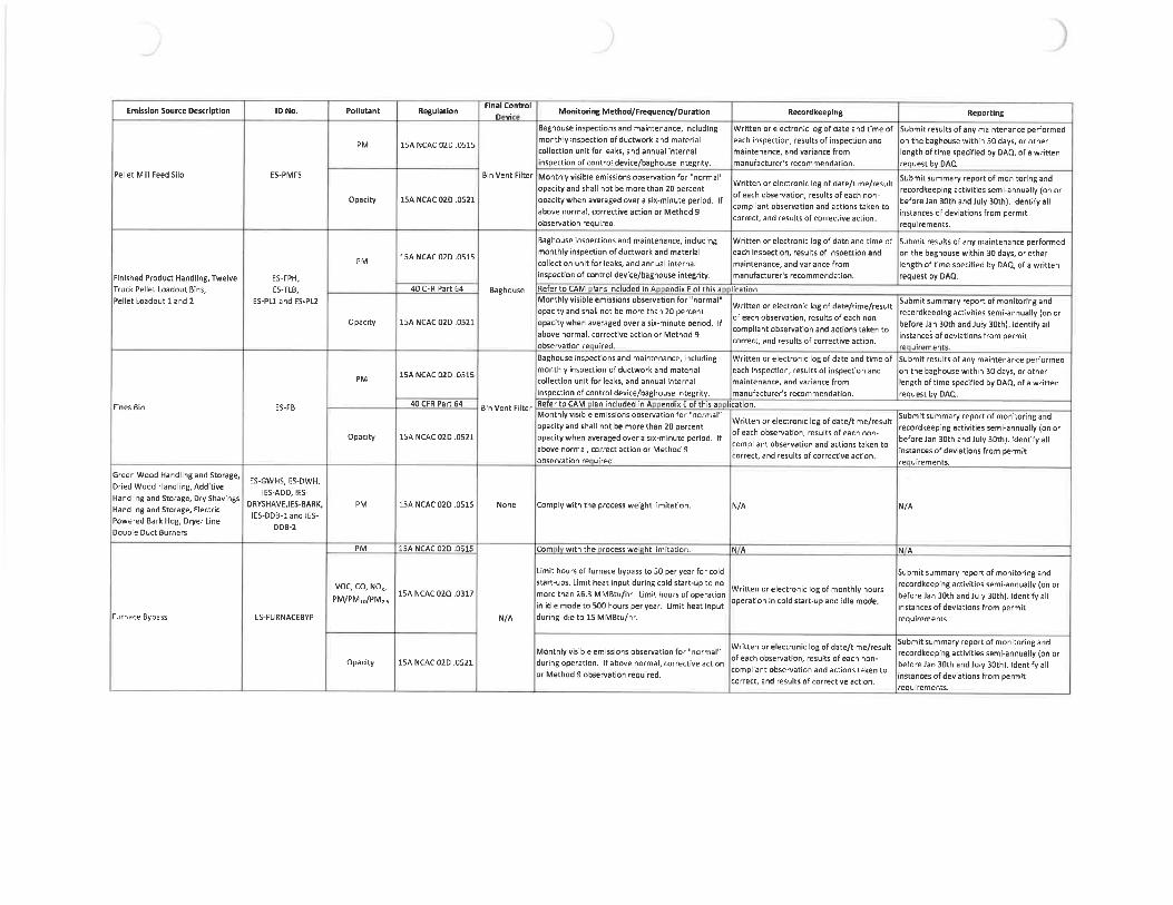
Emission Source Description
Pellet Mill Feed Silo
Finished Product Handling, Twelve ES-FPH,Truck Pellet Loadout Bins, ES-TLB,
Pellet Loadout 1 and 2 ES-PL1 and ES-PL2
Green Wood Handling and Storage,Dried Wood Handling, Additive
Handling and Storage, Dry ShavingsHandling and Storage, ElectricPowered Bark Hog, Dryer Line
Double Duct Burners
ES-GWHS. ES-DWH,
IES-ADD. IES-
DRYSHAVE. IES-BARK,
lES-DOB-landlES-
DDB-2
Pollutant Regulation
PM ISA NCAC02D.0515
Opacity ISA NCACOZD.0521
py, ISA NCAC02D.0515
40 CFR Part 64
Opacity ISA NCAC02D. 0521
p^l ISA NCAC 02D .0515
40 CFR Part 64
Opacity ISA NCAC 02D . 0521
PM ISA NCAC02D. 0515
PM ISA NCAC02D.0515
Final Control
D viMonitoring Method/Frequency/Duration
Furnace Bypass ES-FURNACEBYP
VOC, CO, NO,,PM/PMu/PM,.;
Opacity
ISA NCAC 02Q . 0317
ISA NCAC02D.0521
Baghouse inspections and maintenance, including
monthly inspection of ductwork and materialcollection unit for leaks, and annual internal
inspection of control device/baghouse integrity.
Bin Vent Filter Monthly visible emissions observation for "normal"opacity and shall not be more than 20 percent
opacity when averaged over a six-minute period. If
above normal, corrective action or Method 9
observation required.
Baghouse inspections and maintenance, includingmonthly inspection ofductwork and material
collection unit for leaks, and annual internal
inspection of control device/baghouse integrity.
Baghouse Refer to CAM lans included in A endix E of this aMonthly visible emissions observation for "normal"opacity and shall not be more than 20 percent
opacity when averaged over a six-minute period. Ifabove normal, corrective action or Method 9
observation re uired.
Baghouse inspectiorts and maintenance, includingmonthly inspection of ductwork and material
collection unit for leaks, and annual internal
inspection of control device/baghouse integrity.
BinVentFilter Re^ertocAM lan included in A endixEofthisaMonthly visible emissions observation for "normal"
opacity and shall not be more than 20 percent
opacity when averaged over a six-minute period. Ifabove normal, correct action or Method 9
observation re uired.
None Comply with the process weight limitation.
Corn I with the rocesswei ht limitation.
Limit hours of furnace bypass to 50 per year for coldstart-ups. Limit heat input during cold start-up to no
Record keeping
Written or electronic logof date and time ofeach inspection, results of inspection andmaintenance, and variance from
manufacturer's recommendation,
Written or electronic log of date/time/result
of each observation, results of each non-
compliant observation and actions taken to
correct, and resultsof corrective action.
Written or electronic lag of date and time ofeach inspection, results of inspection andmaintenance, and variance from
manufacturer's recommendation.
lication,
Written or electronic log of date/time/resultof each observation, results of each non-
corn pliant observation and actions taken to
correct, and results of corrective action.
Written or electronic log of date and time of
each inspection, results of inspection andmaintenance, and variance from
manufacturer's recommendation.
lication.
Written or electronic log of date/time/resultof each observation, results of each non-
compliant observation and actions taken to
correct, and results of corrective action.
Reporting
Submit results of any maintenance performedon the baghouse within 30 days, or otherlength of time specified by DAQ. of a writtenrequest by DAQ.
Submit summary report of monitoring andrecordkeeping activities semi-annually (on orbefore Jan 30th and July 30th). Identify allinstances of deviations from permitrequirements.
Submit results of any maintenance performed
on the baghouse within 30 days, or otherlength of time specified by DACL of a writtenrequest by DAQ.
Submit summary report of monitoring andrecordkeeping activities semi-annually (on orbefore Jan 30th and July 30th). Identify allinstances of deviations from permitre uirements.
Submit results of any maintenance performedon the baghouse within 30 days, or otherlength of time specified by DAQ, of a written
request by DAQ..
Submit summary report of monitoring andrecordkeeping activities semi-annually (on orbefore Jan 30th and July 30th). Identify allinstances of deviations from permitre uirements.
N/A N/A
Submit summary report of monitoring andrecord keeping activities semi-annually (on or
N/A
mere than 26. 3 MMBtu/hr. Limit hours of operation w'lt ter^r, electTO"lck'B°f^°"thlv^urs befcre'Ja^Mh"and'Julv30th)"ld^in idle mode to 500 hours peryear. 'Umit heat input
°perat'°" '" rald start-up a"d idte r"ode- instances'crfde»^l;roml pe^it'during idle to 15 MMBtu/hr. requirements.
Mon.. yv,,,. ee. issionso^^on^"nc^al» w^^ectrc ^^d"e/t^result ^^a^S^S^ord:5S^E-5u^r:cti:^°" ^>a:^:.e:^,^Z. ^3^^^1a^^^cor Method 9 observation required. ^.';,'".."'.'.^~.?.'. ',L"^'.~. 1".".̂ ."1 '.''-I"""" " instances of deviations from permit
correct, and results of corrective action.requirements.

Emission Source Description
Emergency Generator
Firewater Pump
Pollutant Regulation
PM. CO. NQ,,, 40 CFR Part 60
NMHC. SO; Subpartllll
SO, ISA NCACD2D. 0516
Opacity ISA NCAC 020 .0521
Final Control
D .MonitoringMethod/Frequency/Duration Recordkeeping Reporting
HAPs40 CFR Part 63
SubpartZZZZ
SO, ISA NCAC 02D . 0516
Opacity ISA NCAC02D.0521
40 CFR Part 63
SubpartZZZZ
N/A
N/A
N/A
N/A
N/A
N/A
N/A
All requirements are outlined in the regulation,including the following; use certified emergencyengines, operate less than 100 hours per year for
non-emerency use, operate according tc ' Maintain^records of engme certification, 1^manufacturers procedure, use fuel oil with fuel ""iti""""' '"d hours/year of operation ofcontent of no more than 15 ppmw sulfur and cetaneindex of at least 40, install non-resettable hour
meter.
Not required because inherently low sulfur content of fuel achieves compliance.
Monthly visible emissions observation for "normal"
opacity during operation (only applicable if Written or electronic log of date/time/resultequipment is operated] and shall not be more than of each observation, results of each non-
20 percent opacity when averaged over a six-minute compliant observation and actions taken toperiod. If above normal, corrective action or correct, and results of corrective action.
Method 9 observation required.
Comply with the NSP5 requirements. No other Comply with the NSPS requirements. Norequirements apply, other requirennents apply.Not required because inherently low sulfur content of fuel achieves compliance.
Monthly visible emissions observation for "normal"opacity during operation (only applicable if Written or electronic log of date/time/resultequipment is operated) and shall not be more than of each observation, results of each non-20 percent opacity when averaged over a six-minute compliant observation and actions taken to
period. If above normal, corrective action or correct, and results of corrective action.Method 9 observation required.
All requirements are outlined in the regulation,including the following: operate less than 100 hours
per year for non-emerency use, operate according to Maintain records of maintenance conductedmanufacturers procedures, install non-resettablehour meter, perform maintenance and inspections
as required.
and hours/year of operatian of each engine.
N/A
Submit summary report of monitoring a ndrecordkeeping activities semi-annually (on orbefore Jan 30th and July 30th). Identify allinstances of deviations from permit
requirements.
N/A
Submit summary report of monitoring andrecordkeeping activities semi-annually (on orbefore lan 30th and July 30th). Identify allinstances of deviations from permit
requirements.
N/A

FORM E4EMISSION SOURCE COMPLIANCE SCHEDULE
REVISED 09/22/16 NCDEQ/Division of Air Quality - Application for Air Permit to Construct/Operate
COMPLIANCE STA TUS WITH RESPECT TO ALL APPLICABLE RE UIREMENTS
E4
Will each emission source at your facility be in compliance with all applicable requirements at the time of permit issuance and continue tocomply with these requirements?
[_d YES Q NO If NO, complete A through F below for each requirement for whichcompliance is not achieved.
Will your facility be in compliance with all applicable requirements taking effect dunng the term of the permit and meet such requirements on atimely basis?
Ld YES D NO if NO, complete A through F below for each requirement for whichcompliance is not achieved.
If this application is for a modification of existing emissions source(s), is each emission source currently in compliance with all applicablerequirements?
_J YES Q NO If NO, complete A through F below for each requirement for whichcompliance is not achieved.
A Emission Source Description (Include ID NO.)
B. Identify applicable requirement for which compliance is not achieved:
C. Narrative description of how compliance will be achieved with this applicable requirements:
D. Detailed Schedule of Compliance:Step(s) Date Ex ected
E. Frequency for submittal of progress reports (6 month minimum):
F. Starting date ofsubmittal of progress reports:
Attach Additional Sheets As Necessary

REVISED 09/22/16
FOR E5TITLE V COMPLIANCE CERTIFICATION (Required)
NCDEQ/Division of Air Quality - Application for Air Permit to Construct/Operate E5
In accordance with the provisions of Title 15A NCAC 2Q .0520 and .0515(b)(4) the responsible company official of:
SITE NAME;
SITE ADDRESS:
CITY, NC :
COUNTY:
PERMIT NUMBER:
Enviva Pellets Ahoskie, LLC
142 N.C. Route S61 East
Ahoskie, North Carolina
Hertford
10121T04
Received
SEP 0 1 2020
^^tfflite Section
CERTIFIES THAT (Check the appropriate statement(s):
_1| The facility is in compliance with all applicable requirements
In accordance with the provisions of Title 15A NCAC 2Q .0515(b)(4) the responsible company official certifies that the proposedminor modification meets the criteria for using the procedures set out in 2Q .0515 and requests that these procedures be used toprocess the permit application.
The facility is not currently in compliance with all applicable requirements
If this box is checked, you must also complete Form E4 "Emission Source Compliance Schedule"
The undersigned certifies under the penalty of law, that all information and statements provided in the application,based on information and belief formed after reasonable inquiry, are true, accurate, and complete.
^c^ Date:
Si ure f responsible co pany official (REQUIRED, USE BLUE INK)^^-aiO^O
Curtis Hall, Plant ManagerName, Title of responsible company official (Type or print)
Attach Additional Sheets As Necessary

REVISED 09/22/16
FORM E6COMPLIANCE ASSURANCE MONITORING (CAIVI) PLAN (4 pages)
NCDEQ/Division of Air Quality - Application for Air Permit to Construct/Operate E6-1
For CAM-affected emission units, the applicant must submit additional information in the form of a CAM Plan as required under 40 CFR 64.
For information about the CAM rule and this form, please refer to 40 CFR 64 and 15A NCAC 2D . 0614.Additional information (including guidance documents may be found at the following URLs:
htt s://www3. e a. ov/ttn/emc/cam. htmlhtt s://de . nc. ov/about/divisions/air- uali /air ualit -enforcement/com liance-assurance-monitorin
SOURCE INFORMATIONaci 1 ame: nviva e ets os ie,ermit um er: 10121 04a e arm re are : 22- un-20
BASIS OF CAM SUBMITTAL4. Mark the appropriate box below as to why this CAM Plan is being submitted as part of this application:
[^ Renewal Application: AL^ Emission Units (Pollutant Specific Emission Units [PSEUs] considered separately with respect to EACH regulated airpollutant) for which a CAM Plan has NOT yet been approved needs to be addressed in this CAM Plan submittal.See Renewal Procedures per 15 A NCAC 2Q . 0513.
[_ Initial Application (Submitted after 4/20/1998): Only large PSEUs (PSEUs with potential post control device emissions of an applicable regulated airpollutant that are equal to or greater than major source threshold levels) need to be addressed in this CAM Plan submittal.See Initial Application Procedures per 15A NCAC 2Q . 0505(1).
[_ Significant Modification to Large PSEUs: Only large PSEUs (PSEUs wVn potential post control device emissions of an applicable regulated airpollutant that are equal to or greater than major source threshold levels) being modified after 4/20/1998 need to be addressed in this CAM Plan submittal.For large PSEUs with an approved CAM Plan, only address the appropriate monitoring requirements affected by the significant modification.See Significant Modification Procedures per 15 A NCAC 2Q . 0516.
CAM APPLICABILITY DETERMINATION5. To determine CAM applicability, a PSEU must meet ALL of the following criteria (If not, then the remainder of this form need not be completed):
A. The PSEU is located at a major source;B. The PSEU is subject to an emission limitation or standard for the applicable regulated air pollutant that is NOT exempt;
List of EXEMPT Emission Limitations or Standards below OR as rovided in 15A NCAC 2Q . 0614 b 1 :« NSPS (40 CFR Part 60) or NESHAP (40 CFR Part 61 and 63) proposed after 11/15/1990.. Stratospheric ozone protection requirements.. Acid Rain program requirements.. Emission limitations or standards for which a Title V permit specifies a continuous compliance determination method, as defined in the
CAM rule (40 CFR 64. 1), Continuous Compliance Determination Method.. An emission cap that meets the requirements specified in 40 CFR 70. 4(b)(12).If the PSEU is subject to both Exempt and Not Exempt emission standards for the same pollutant, then the facility is required to determine theCAM applicability for Not Exem t emission standards.
C. The PSEU uses an add-on control device to achieve compliance with an emission limitation or standard;D. The PSEU has potential pre-control device emissions of the applicable regulated air pollutant that are equal to or greater than major source
threshold levels; and
E. The PSEU is NOT an exempt backup utility power emission unit that is municpally owned and appropriately documentd as provided in15ANCAC2D.0614(b)(2).
Attach Additional Sheets As Necessary Page 1 of 4

BACKGROUND DATA AND INFORMATION6. Complete the following table for ALL PSEUs that need to be addressed in this CAM Plan submittal. This section is to be used to provide
background data and information for each PSEU in order to supplement the submittal requirements specified in 40 CFR 64.4.If additional s ace is needed, please attach and label additional sheets as a
mission
PSEU PSEU Control Limitation OR "MonitoringDes ation Descr' on . . Standard P irement
See CAM Plans in Appendix E
n ica e e emission imi a ion or stan ar or any app ica e requirement t at constitutes an emisson imitation, emission s an a , or stan a operformance. Examples of emission limitations or standards may include a pennitted emission limitation, applicable regulations, work practices, process orcontrol device parameters, or other forms of specific design, equipment, operational or maintenance requirements,Indicate the monitoring requirements for the control device that are required by an applicable regulation or permit condition.
Attach Additional Sheets As Necessary Page 2 of 4

' CAM MONITORING APPROACH CRITERIA
Complete this section for EACH PSEU and for each affected pollutant that needs to be addressed in this CAM Plan submittal. This section may becopied as needed for each PSEU. This section is to be used to provide monitoring data and information for EACH indicator selected for EACH PSEU inorder to meet the monitoring design criteria specified in 40 CFR 64. 3 and 64. 4. If more than two indicators are being selected for a PSEU or ifadditional space is need, attach and label with the apprtopriate PSEU designation, pollutant, and indicator Nos.
POLLUTANT INDICATOR 1 INDICATOR NO. 2
See CAM Plans in Appendix E
7a. General Criteria
Describe the monitoring approach used tomeasure the indica o .
s a is e appropna e in ica or ran e orthe procedures for establishing the indicatorrange which provides a reasonableassurance of compliance
rovi e uai m rovemen an
Threshold levels.
7b. Performance criteria
Provide the S ecification for ObtaininRe resentative Data (Such as detectorlocation and installation s ecifications).Provide Qualit Assurance and Qualit
Control QA/QC Practices that are adequateto ensure the continuing validity of the data,considering manufacturerer'srecommendations
e Provide the Monitoring Frequency
Provide the Data Collection Procedures that
will be used
Provide the Data Avera in Period for thepurpose of determining whether anexcursion or exceedance has occurred,
If a Continuous Emission Monitoring System (CEMS), Continuous Opacity Monitoring System (COM3), or Predictive Emission Monitoring System (PEMS) isused, then this section need not be completed ONLY for the CEMS, COM3, or PEMS. EXCEPT that the Special Criteria Information of 40 CFR 64. 3(d) must beprovided. Special Criteria Information may be provided on a separate sheet.
Describe all indicators to be monitored which satisfy 40 CFR 64. 3(a), Indicators of emission control performance for the control device and associated capturesystem may include measured or predicted emissions (including visible emissions or opacity), process and control device operating parameters that affect controldevice (and capture system) efficiency or emission rates, or recorded findings of inspection and maintenance activities.
Indicator ranges may be based on a single maximum or minimum value or at multiple levels that are relevant to distinctly different operating conditions, expressedas a function of process variables, expressed as maintaining the applicable indicator in a particular operational status or designated condition, or established asinterdependent between more than one indicator. In addition, unless specifically stated otherwise by an applicable requirement, the owner or operator shallmonitor the indicators to detect any bypass of the control deivce (or capture system) to the atmosphere.The QIP threshold is based on the number of excursions identified in a reporting period. (Example: if the historical monitoring data for a facility indicates that theindicator range was exceeded 10 times in a 6-month period, the threshold could be established at no more than 10 excursions outside the indicator range during a6-month reporting period. ) The threshold levels also could be established based on the duration of excursions as a percentage of operating time.
At a minimum, the owner of a large PSEU must collect four or more data values equally spaced over each hour and average the values. All other PSEUs mustcollect data at least once per 24-hour period or possibly more to provide reasonable assurance of complliance over the anticipated range of operatingconditions.
Attach Additional Sheets As Necessary Page 3 of 4

RATIONALE AND JUSTIFICATION
Complete this section for EACH PSEU and for each affected pollutant that needs to be addressed in this CAM Plan submittal. This section may becopied as needed. Use this section to provide monitoring data and information for EACH indicator selected for EACH PSEU in order to meet themonitoring design criteria specified in 40 CFR 64. 3 and 64. 4. If more than two indicators are being selected for a PSEU or if additional speace isneeded, attach additional sheets and label with the appropriate PSEU designation, pollutant, and indicator Nos.
.H4in*iM;r. f -. I. ''
INDICATORS AND THE MONITORING APPROACH: Provide the rationale and justification for the selection of the indicators and the monitoring approach usedto measure the indicators. Also provide any data suporting the rationale and justification. Explain the reasons for any differences between the verification ofoperational status or the quality assurance and control practices proposed and the manufacturer's recommendations (If additional space is needed, attach andlabel with the appropirate PSEU designation and pollutant).
See CAM Plans in Appendix E
0. INDICATOR RANGES: Provide the rationale and justification for the selection of the indicator ranges. The rationale and justification shall indicate how EACHindicator range was selected by either a Corn liance or Performance Test, a Test Plan and Schedule, or by En ineerin Assessments. Depending on whichmethod is being used for each indicator range, include the specific information required below for that specific indicator range. (If additional space is needed,attach and label with the appropriate PSEU designation and pollutant):
. COMPLIANCE or PERFORMANCE TEST (Indicator ranges determined from control device operating parameter data obtained during a compliance orperformance test conducted under regulatory specified conditions or under conditions representative of maximum potential emissions under anticipatedoperating conditions. Such data may be supplemented by engineering assessments and manufacturer's recommendations). The rationale and justificationshall include a summary of the compliance or performance test results that were used to determine the indicator range and documentation indicating that nochanges have taken place that could result in a significant change in the control system perfomrnace or the selected indicator ranges since the compliance orperformante test was conducted and approved by DAQ.
. TEST PLAN AND SCHEDULE (Indicator ranges will be determined from a proposed implementation plan and schedule for installing, testing, and performingany other appropriate activities pnor to use of the monitoring). The rationale and justification shall include the proposed implementation plan and scheduiethat will provide for use of the monitoring as expeditiously as practical after approval of this CAM Plan, but in no case shall the schedule for completinginstallation and beginning operation of the minitoring exceed 180 days after approval.
. ENGINEERING ASSESSMENTS (Indicator ranges or the procedures for establishing indicator ranges are determined from engineering assessments andother data, such as manufacturer's design criteria and historical monitoring data, because factors specific to the type of monitoring, control device, or PSEUmake compliance or performance testing unnecessary). The rationale and justification shall include documentaion demonstrating that compliance testing ;snot required to establish the indicator range.
RATIONALE AND JUSTIFICATION:
See CAM Plans in Appendix E
Attach Additional Sheets As Necessary Page 4 of 4

FORM BSPECIFIC EMISSION SOURCE INFORMATION (REQUIRED FOR ALL SOURCES)
REVISED 09/22/16 NCDEQ/Division of Air Quality - Application for Air Permit to Construct/OperateEMISSION SOURCE DESCRIPTION: EMISSION SOURCE ID NO: ES-GWHSGreen Wood Handling and Storage CONTROL DEVICE ID NO(S): NoneOPERATING SCENARIO OF 1 EMISSION POINT (STACK) ID NO(S): EP-15DESCRIBE IN DETAILTHE EMISSION SOURCE PROCESS (ATTACH FLOW DIAGRAM):Green wood chips and bark are delivered to the plant via trucks. The green wood handling and storage emission source (ES-GWHS] representsall green wood chip and bark transfer points and storage piles.
TYPE OF EMISSION SOURCE (CHECK AND COMPLETE APPROPRIATE FORM B1-B9 ON THE FOLLOWING PAGES):U- Coal,wood,oil, gas, other burner (Form B1) Q Woodworking (Form B4) U_ Manuf. of chemicals/coatings/inks (Form B7)^ Int.combustion engine/generator (Form B2) Coating/finishing/printing (Form B5) IIncineration (Form B8)
Li uid stora e tanks Form B3 Stora e silos/bins Form B6 -/ Other Form B9U Tl N DAT : DA E MAN FA U
MANUFACTURER / MODEL NO.:
IS THIS SOURCE SUBJECT T<PERCENTAGE ANNUAL THRO
DAY/WK , 52 WhyYNSPS SUBPARTS?
^HPUT DEC-FEB 25%
AIR POLLUTANT EMITTEDPARTICULATE MATTER (PM)PARTICULATE MATTER<10 MICRONS (PMio)PARTICULATE MATTER<2.5 MICRONS (PM^s)SULFUR DIOXIDE (S02)NITROGEN OXIDES (NOx)CARBON MONOXIDE (CO)VOLATILE ORGANIC COMPOUNDS (VOC)LEADOTHER
AIR
SOURCE 0EMISSIONFACTOR
EXPECTED OP. SCHEDULE: _24_ HR/DAYNESHAP SUBPARTS?):
MAR-MAY 2!;% JUN-AUG 25% SEP- 3V 25%. t .
EXPECTED ACTUAL POTENTIAL EMISSIONS(AFTER CONTROLS / LIMITS) (BEFORE CONTROLS / LIMITS) (AFTER CONTROLS / LIMITS)
Ib/hr tons/yr Ib/hr tons/yr Ib/hr tons/yr
See Emission Calculations in Appendix C
LLU
HAZARDOUS AIR POLLUTANT CASNO.
ANTESOURCE 0EMISSIONFACTOR
IONS F REXPECTED ACTUAL
(AFTER CONTROLS / LIMITS)Ib/hr tons/yr
ON F RTHI S RCPOTENTIAL EMISSIONS
(BEFORE CONTROLS / LIMITS) (AFTER CONTROLS / LIMITS)
Ib/hr tons/ r Ib/hr tons/yr
N/A
TOXIC AIR POLLUTANT
A T
OFGAS NO. EMISSION
A I N OR TH IEXPECTED ACTUAL EMISSIONS AFTER CONTROLS / LIMITATIONS
Ib/hr Ib/da Ib/yr
N/A
.Attachments: (1) emissions calculations and supporting documentation; (2) indicate all requested state and federal enforceable permit limits (e. g. hours of operation, emission[rates) and describe how these are monitored and with what frequency; and (3) describe any monitoring devices, gauges, or test ports for this source.3MPLETE THIS FORM AND COMPLETE AND ATTACH APPROPRIATE 67 THROUGH B9 FORM hUK fc/IC"M SUUH
Attach Additional Sheets As Necessary

hUKIVI ByEMISSION SOURCE (OTHER)
REVISED 09/22/16 NCDEQ/Division of Air Quality-Application for Air Permit to ConstrucVO erate B9EMISSION SOURCE DESCRIPTION: EMISSION SOURCE ID NO: ES-GWHS
Green Wood Handling and Storage CONTROL DEVICE ID NO(S): NoneOPERATING SCENARIO: 1 OF _1_ EMISSION POINT (STACK) ID NO(S): EP-15DESCRIBE IN DETAIL THE PROCESS (ATTACH FLOW DIAGRAM):Green wood chips and bark fuel are delivered to the plant via trucks. The green wood handling and storage emission source (ES-GWHS)represents all green wood chip and bark transfer points and storage piles.
MATERIALS ENTERING PROCESS - CONTINUOUS PROCESTYPE UNITS
Green Wood Materials er emission point tons wet
MAX. DESIGN
CAPACITY (UNIT/HR)400
REQUESTED CAPACITl'LIMITATION(UNIT/HR
NA
MATERIALS ENTERINGPROCESSTYPE
BATCH OPERA ON MAX. DESIGNUNITS CAPACITY (UNIT/BATCH)
REQUESTED CAPACITY
LIMITATION (UNIT/BATCH)
MAXIMUM DESIGN (BATCHES / HOUR):REQUESTED LIMITATION (BATCHES / HOUR):
FUEL USED: N/AMAX. CAPACITY HOURLY FUEL USE: N/A
COMMENTS:
(BATCH ES/YR):
TOTAL MAXIMUM FIRING RATE (MILLION BTU/HR): N AREQUESTED CAPACITY ANNUAL FUEL USE: N/A
Attach Sheets as Necessary

FOKIVI BSPECIFIC EMISSION SOURCE INFORMATION (REQUIRED FOR ALL SOURCES)
REVISED 09/22/1 NCDEQ/Division of Air Quality - Application for Air Permit to Construct/OperateEMISSION SOURCE DESCRIPTION: EMISSION SOURCE ID NO: ES-GHM-1, 2, 3, 4Green Hammermills CONTROL DEVICE ID NO(S): CD-WESP, CD-RTOOPERATING SCENARIO OF EMISSION POINT (STACK) ID NO(S): EP-1SDESCRIBE IN DETAILTHE EMISSION SOURCE PROCESS (ATTACH FLOW DIAGRAM):Prior to drying, chips from the green wood storage piles will be processed in the green hammermills to reduce material to the proper size.
TYPE OF EMISSION SOURCE (CHECKAND COMPLETE APPROPRIATE FORM B1^B9 ON THE FOLLOWING PAGES):[Z. Coal, wood, oil, gas, other burner (Form B1) Q Woodworking (Form B4) ^ Manuf. ofchemicals/coatings/inks(Form B7)[~ lnt. combustionengine/generator(FormB2) || Coating/finishing/printing (Form B5) IIncineration (Form B8)
Li uid stora e tanks Form B3 Stora e silos/bins Form B6 j Other Form B9UFA TURED:
MANUFACTURER / MODEL NO.:GHM-1:N A; GHM-2, 3, 4:TBDIS THIS SOURCE SUBJECT NSPS (SUBPARTS?):PERCENTAGE ANNUAL THROUGHPUT (%): DEC-FEB 23%
EXPECTED OP. SCHEDULE: ^24_ HR/DAYNESHAP SUBPARTS?:
MAR-MAY 25% JUN-AUG 25% SEP-NOV 25%
DAY/WK _52_WW>f
AIR POLLUTANT EMITTED
PARTICULATE MATTER (PM)PARTICULATE MATTER<10 MICRONS (PMio)PARTICULATE MATTER<2.5 MICRONS (PMzs)SULFUR DIOXIDE (S02NITROGEN OXIDES (NOx)CARBON MONOXIDE (CO)VOLATILE ORGANIC COMPOUNDS (VOC)LEADOTHER
D SAfR
SOURCE 0EMISSIONFACTOR
EXPECTED ACTUAL(AFTER CONTROLS / LIMITS)
Ib/hr tons/yr
POTENTIAL EMISSIONS(BEFORE CONTROLS / LIMITS) (AFTER CONTROLS / LIMITS)
Ib/hr tons/yr Ib/hr tons/yr
HAZARDOUS AIR POLLUTANT
OLLUTANTSOURCE 0EMISSION
GAS NO. FACTOR
See Emission Calculations in Appendix C
0 S INFO ATION FOR THIS S U CEXPECTED ACTUAL POTENTIAL EMISSIONS
(AFTER CONTROLS / LIMITS) (BEFORE CONTROLS / LIMITS) (AFTER CONTROLS / LIMITS)
Ib/hr tons/ r Ib/hr tons/yr Ib/hr tons/ r
See Emission Calculations in Appendix C
TOXIC AIR POLLUTANT
/ POLLUTANT EMI Sl NS I F RMATION FOR HIEXPECTED ACTUAL EMISSIONS AFTER CONTROLS / LIMITATIONS
CASNO. EMISSION Ib/hr Ib/day Ib/yr
See Emission Calculations in Appendix C
Attachments: (1) emissions calculations and supporting documentation; (2) indicate all requested state and federal enforceable permit limits (e. g. hours of operation,emission rates) and describe how these are monitored and with what frequency; and(3)describe any monitoring devices, gauges, or test ports for this source.WPLETE THIS FORM AND COMPLETE AND ATTACH APPROPRIATE B1 THROUGH B9 FORM FOR SACH SOUH
Attach Additional Sheets As Necessary

FOKIVI B9EMISSION SOURCE (OTHER)
NCDEQ/Division of Air Quality - Application for Air Permit to ConstrucVOperate B9EMISSION SOURCE ID NO: ES-GHM-1, 2, 3, 4
CONTROL DEVICE ID NO(S): CD-WESP, CD-RTO
OPERATING SCENARIO: 1 OF 1 EMISSION POINT (STACK) ID NO(S): EP-18
DESCRIBE IN DETAIL THE PROCESS (ATTACH FLOW DIAGRAM):Prior to drying, chips from the green wood storage piles will be processed in the green hammermills to reduce material to the proper size.
REVISED 09/22/16EMISSION SOURCE DESCRIPTION:Green Hammermills
MATERIALS ENTERING PROCESS - CONTINUOUS PROCESSTYPE UNITS
Green Wood ODT
MAX. DESIGNCAPACITf' (UNIT/HR)
63
REQUESTED CAPACIPi'LIMITATION(UNIT/HR)
N A
MATERIALS ENTERING PROCESSTfPE
BATCH OPERATIONUNITS
MAX. DESIGNCAPACITC UNIT/BATCH
REQUESTED CAPACITfLIMITATION UNIT/BATCH
MAXIMUM DESIGN BATCHES / HOUR):REQUESTED LIMITATION (BATCHES / HOUR):
FUEL USED: N AMAX. CAPACITY HOURLY FUEL USE: N/ACOMMENTS:
(BATCHES/YR
TOTAL MAXIMUM FIRING RATE (MILLION BTU/HR): N AREQUESTED CAPACITY ANNUAL FUEL USE: N/A
Attach Additional Sheets as Necessary

FORM BSPECIFIC EMISSION SOURCE INFORMATION (REQUIRED FOR ALL SOURCES)
REVISED 09/22/11 NCDEQ/Division of Air Quality-Application for Air Permit to Construct/OperateEMISSION SOURCE DESCRIPTION: EMISSION SOURCE ID NO: ES-DRYERDryer (Green Wood Direct-Fired Dryer System) CONTROL DEVICE ID NO(S): CD-WESP, CD-RTOOPERATING SCENARIO 1 OF EMISSION POINT (STACK) ID NO(S): EP-18DESCRIBE IN DETAILTHE EMISSION SOURCE PROCESS (ATTACH FLOW DIAGRAM):Green wood Is conveyed to a rotary dryer system. Direct contact heat is provided to the system via a 175. 3 MMBtu/hr furnace. Air emissionswill be controlled uUlizing an existing wet elertrostaUc precipitator (CD-WESP) for parUculate removal. VOC and organic HAP emissions willbe controlled by a new regenerative thermal oxidizer (CD-RTO). A bypass stack for the dryer furnace (ES-FURNACEBYP) will be used toexhaust hot gases during cold startup and idle-mode.
TYPE OF EMISSION SOURCE (CHECK AND COMPLETE APPROPRIATE FORM B1^9 ON THE FOLLOWING PAGES):[Z Coal, wood, oil, gas, other burner (Form 81) Q Woodworking (Form B4) C Manuf. ofchemicals/coatings/inks (Form 87)^_ lnt. combustionengine/generator(Form B2) Q Coating/finishing/printing (Form 85) |_ Incineration (Form B8)
Li uid stora e tanks Form B3 Stora e silos/bins Form B6 Other Form B9TART N R DA : DA M RD:
MANUFACTURER / MODEL NO.:Teaford
IS THIS SOURCE SUBJECT . NSPS (SUBPARTS?):PERCENTAGE ANNUAL THROUGHPUT (%): DEC-FEB 23%
EXPECTED OP. SCHEDULE: 2A HR/DAYNESHAP (SUBPARTS?):
MAR-MAY 25% JUN-AUG 25% SEP-NOV 25%
AIR POLLUTANT EMITTEDPARTICULATE MATTER (PM)PARTICULATE MATTER<10 MICRONS (PM, o)PARTICULATE MATTER<2. 5 MICRONS (PMzs)SULFUR DIOXIDE (S02)NITROGEN OXIDES (NOx)CARBON MONOXIDE (CO)VOLATILE ORGANIC COMPOUNDS (VOC)LEADOTHER
USA
SOURCE 0EMISSIONFACTOR
DAY/WK _52^WKA'
HAZARDOUS AIR POLLUTANT
PO LUTANTESOURCE 0EMISSION
CAS NO. FACTOR
EXPECTED ACTUAL POTENTIAL ENtlSSIONS(AFTER CONTROLS / LIMITS) (BEFORE CONTROLS / LIMITS) (AFTER CONTROLS / LIMITS)
Ib/hr tons/yr Ib/hr tons/yr Ib/hr tons/yr
See Emission Calculations in Appendix C
S N INF MAIO FEXPECTED ACTUAL POTENTIAL EMISSIONS
(AFTER CONTROLS / LIMITS) (BEFORE CONTROLS / LIMITS) (AFTER CONTROLS / LIMITS)
Ib/hr tons/yr Ib/hr tons/ r Ib/hr tons/ r
See Emission Calculations in Appendix C
TOXIC AIR POLLUTANT
0)aC AIR POLLUT NT EMISSIONS INFO MATI N R THIS SOUR EEXPECTED ACTUAL EMISSIONS AFTER CONTROLS / LIMITATIONS
GAS NO. EMISSION Ib/hr Ib/day Ib/ r
See Emission Calculations in Appendix C
Attachments: (1) emissions calculations and supporting documentation; (2) indicate all requested state and federal enforceable permit limits (e. g. hours of operation,emission rates) and describe how these are monitored and with what frequency; and (3) describe any monitoring devices, gauges, or test ports for this source.
Attach Additional Sheets As Necessary
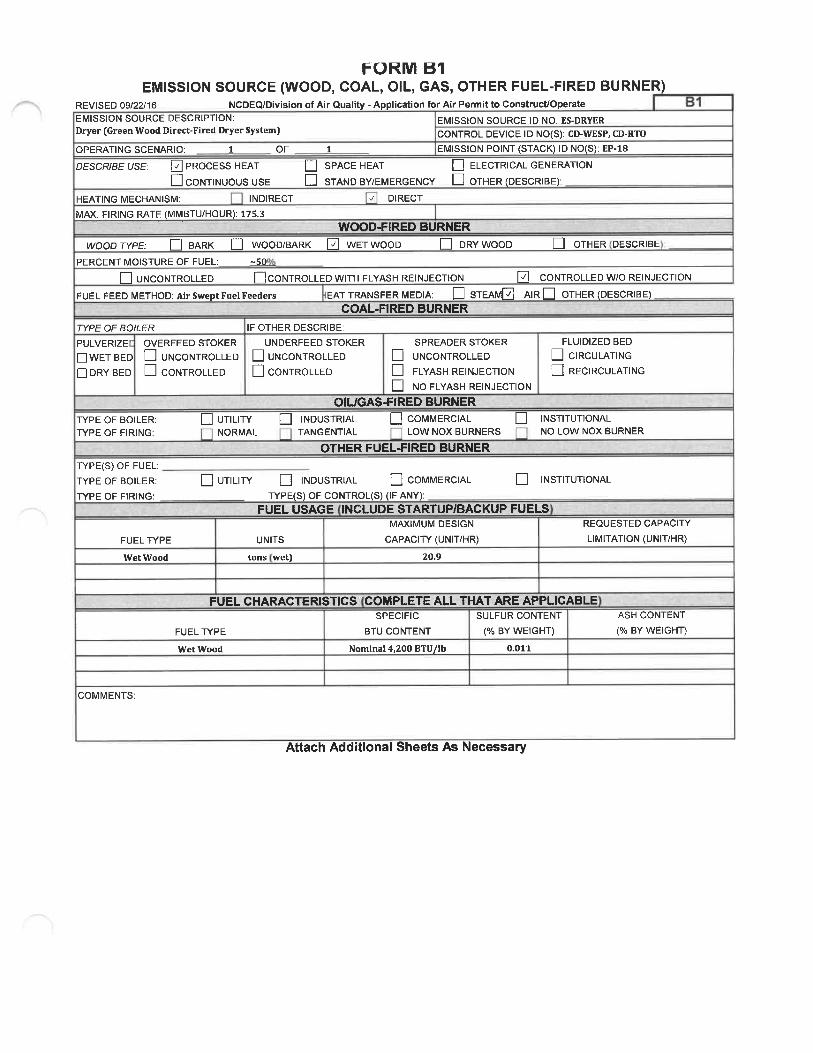
FORIVI 81EMISSION SOURCE (WOOD, COAL, OIL, GAS, OTHER FUEL-FIRED BURNER)
REVISED 09/22/16 NCDEQ/Division of Air Quality - Application for Air Permit to Construct/OperateEMISSION SOURCE DESCRIPTION:Dryer (Green Wood Direct-Fired Dryer System]
OPERATING SCENARIO: 1 OF
DESCRIBE USE: I ̂ I PROCESS HEAT
D CONTINUOUS USEHEATING MECHANISM: INDIRECT
MAX. FIRING RATE (MMBTU/HOUR): 17S.3
EMISSION SOURCE ID NO: ES-DRYER
CONTROL DEVICE ID NO(S): CD-WESP, CD-RTO1 EMISSION POINT (STACK) ID NO(S): EP-18
D SPACE HEAT [_j ELECTRICAL GENERATIOND STAND BY/EMERGENCY D OTHER (DESCRIBE):
^ DIRECT
WOOD-FIRED BURNERWET WOOD D DRY WOOD Q OTHER DESCRIBEWOOD TYPE: LI BARK |_| WOOD/BARK
PERCENT MOISTURE OF FUEL: -50
UNCONTROLLED DCONTROLLED WITH FLYASH REINJECTIONFUEL FEED METHOD: Air Swept Fuel Feeders EAT TRANSFER MEDIA: D STE,
_d CONTROLLED W/0 REINJECTION
AIR D OTHER (DESCRIBE)COAL.FIRED BURNER
FfPE OF BO/LER
PULVERIZE OVERFEED STOKERD WET BED D UNCONTROLLEDD DRY BED U CONTROLLED
IF OTHER DESCRIBE:
UNDERFEED STOKER
UNCONTROLLED
D CONTROLLED
TYPE OF BOILER:TYPE OF FIRING:
r^PE(S) OF FUEL:TYPE OF BOILER:
r>rPE OF FIRING:
FUELTl'PE
Wet Wood
UTILITYNORMAL
SPREADER STOKER
UNCONTROLLED
FLYASH REINJECTION
NO FLYASH REINJECTION
OIUGAS-FIRED BURNERINDUSTRIAL |_] COMMERCIAL
TANGENTIAL LOW NOX BURNERS
OTHER FUEL-FIRED BURNER
FLUIDIZED BEDQ CIRCULATINGQ RECIRCULATING
INSTITUTIONALNO LOW NOX BURNER
[_] UTILIPr [_] INDUSTRIAL d COMMERCIALT»-PE(S) OF CONTROL(S) (IF ANY):
FUEL USAGE INCLUDE STARTUP/BACKUP FUELSMAXIMUM DESIGN
UNITS CAPACITl' (UNIT/HR)
tons wet] 20.9
INSTITUTIONAL
REQUESTED CAPACITr
LIMITATION (UNIT/HR)
FUEL CHARACTERISTICS COMPLETE ALL THAT ARE APPLICABLESPECIFIC SULFUR CONTENT
FUEL TYPE BTU CONTENT (% BY WEIGHT)
Wet Wood Nominal 4, 200 BTU/lb 0. 011
ASH CONTENT
(% BY WEIGHT)
COMMENTS:
Attach Additional Sheets As Necessary

FOKMBSPECIFIC EMISSION SOURCE INFORMATION (REQUIRED FOR ALL SOURCES)
REVISED 09/22/16 NCDEQ/Division of Air Quality - Application for Air Permit to Construct/OperateEMISSION SOURCE DESCRIPTION: EMISSION SOURCE ID NO: ES-DHM-1 throu h ES-DHM-7
Seven (7) Dry Hammermills ^^^ ̂ ^ ̂ ^^ CD-DHM.FF1 through CD-DHM.FF3, CD-WESP, CD-RTO
OPERATING SCENARIO 1 OF 1 EMISSION POINT (STACK) ID NO(S): EP-18DESCRIBE IN DETAILTHE EMISSION SOURCE PROCESS (ATTACH FLOW DIAGRAM):Dried materials are reduced to appropriate size needed for pelletizing using seven (7) dry hammermills (5 exisUng and 2 new DHMs beingproposed in this application). Each dry hammermill includes a material recovery cyclone that is routed to one of three (3) baghouses (CD-DHM-FFlthrou CD-DHM-FF3 for articulate matter control.
TyPE OF EMISSION SOURCE (CHECK AND COMPLETE APPROPRIATE FORM B1^B9 ON THE FOLLOWING PAGES);L Coal, wood, oil, gas, other burner (Form B-i) D Woodworking (Form B4) C Manuf. of chemicals/coatings/inks (Form B7)[^ Int.combustionengine/generator (Form 82) D Coating/finishing/printing (Form Bi |_ Incineration (Form B8)
Li uid stora e tanks Form B3 Stora e silos/bins Form B6 j Other Form B9TRU N DATE: DATE MAN FA
MANUFACTURER / MODEL NO. : Bliss. Model 44-60 (ES-DHNI-1 thruES-DHNI-5); TBD (ES-DHM-6 and -7)IS THIS SOURCE SUBJECT T NSPS SUBPARTS?):PERCENTAGE ANNUAL THROUGHPUT (%): DEC-FEB 25%
EXPECTED OP. SCHEDULE: ̂ 24_ HR/DAYNESHAP SUBPARTS?):
MAR-MAY 25% JUN-AUG 25% SEP-NOV 23%
DAY/WK _52_\NW\
AIR POLLUTANT EMITTEDPARTICULATE MATTER (PM)PARTICULATE MATTER<10 MICRONS (PM, o)PARTICULATE MATTER<2.5 MICRONS (PM, s)SULFUR DIOXIDE (S02)NITROGEN OXIDES (NOx)CARBON MONOXIDE (CO)VOLATILE ORGANIC COMPOUNDS (VOC)LEADOTHER
OU Al
SOURCE 0EMISSIONFACTOR
HAZARDOUS AIR POLLUTANT
P LLUT N EMISOURCE 0EMISSION
GAS NO. FACTOR
EXPECTED ACTUAL POTENTIAL EMISSIONS(AFTER CONTROLS / LIMITS) (BEFORE CONTROLS / LIMITS) (AFTER CONTROLS ; LIMITS)
Ib/hr tons/yr Ib/hr tons/yr Ib/hr tons/yr
See Emission Calculations in Appendix C
N S INFORM I NFO HISEXPECTED ACTUAL POTENTIAL EMISSIONS
(AFTER CONTROLS / LIMITS) (BEFORE CONTROLS / LIMITS) (AFTER CONTROLS / LIMITS)Ib/hr tons/ r Ib/hr tons/yr Ib/hr tons/yr
See Emission Calculations in Appendix C
TOXIC AIR POLLUTANT
OXICAIR OL UTA
CAS NO.
EMI SO S INFORM TIONFORT IS SOU CEEXPECTED ACTUAL EMISSIONS AFTER CONTROLS / LIMITATIONS
EMISSIO Ib/hr Ib/da Ib/yr
See Emission Calculations in Appendix C
Attachments: (1) emissions calculations and supporting documentation; (2) indicate all requested state and federal enforceable permit limits (e.g. hours af operation,emission rates) and describe how these are monitored and with what frequency; and (3) describe any monitoring devices, gauges, or test ports for this source.
Attach Additional Sheets As Necessary

FORM 89EMISSION SOURCE (OTHER)
REVISED 09/22/16 NCDEQ/DivisionofAirQuali - Application for Air Permit to Construct/Operate B9EMISSION SOURCE DESCRIPTION: EMISSION SOURCE ID NO: ES-DHM-1 throu ES-DHM-7Seven (7) Dry Hammermills CONTROL DEVICE ID NO(S): CD-DHM-FF1 through CD-DHM-FF3,
CD-WESP, CD-RTO
OPERATING SCENARIO: 1 OF _1_ EMISSION POINT (STACK) ID NO(S): EP-18DESCRIBE IN DETAIL THE PROCESS (ATTACH FLOW DIAGRAM):Dried materials are reduced to appropriate size needed for pelletizing using seven (7) dry hammermills (5 existing and 2 new DHMs beingproposed in this application). Each dry hammermill includes a material recovery cyclone that is routed to one of three (3) baghouses (CD-DHM-FF1 through CD-DHM-FF3] for particulate matter control.
BDATERIALS ENTERING PROCESS - CONTINUOUS PROCESSTYPE UNITS
Dried Wood ODT
MAX. DESIGN
CAPACITf UNIT/HR)
63
REQUESTED CAPACITYLIMITATION(UNIT/HR)
N/A
MATERIALS ENTERING PROCESSFfPE
BATCH OPERATIONUNITS
MAX. DESIGNCAPACITY (UNIT/BATCH)
REQUESTED CAPACIP/LIMITATION (UNIT/BATCH)
MAXIMUM DESIGN (BATCHES / HOUR):REQUESTED LIMITATION BATCHES / HOUR :
FUEL USED: N AMAX. CAPACITY HOURLY FUEL USE: N/ACOMMENTS:
(BATCHES/YR):
TOTAL MAXIMUM FIRING RATE (MILLION BTU/HR):REQUESTED CAPACITY ANNUAL FUEL USE: N/A
N/A
Attach Additional Sheets as Necessary

REVISED 09/22/16
FORM C1CONTROL DEVICE (FABRIC FILTER)
NCDEQ/Division of Air Quality - Application for Air Permit to Construct/Operate
DHM-FF3
EMISSION POINT (STACK) ID NO(S): EP-18
CONTROLS EMISSIONS FROM WHICH EMISSION SOURCE ID NO(S): ES-DHM-1 through ES-DHM-7POSITION IN SERIES OF CONTROLS" NO. 1 OF 3 UNITS
P.E. SEAL REQUIRED (PER 2q .0112)? YES NOOPERATING SCENARIO:
DESCRIBE CONTROL SYSTEM:Three (3) baghouses are utilized for emission control after the exiting seven (7) dry hammermill material recovery cyclones. Hammermllls 1, 2, and 6 vent to CD-DHM-FF1, Hammermills 3, 4, and 7 vent through CD-DHM-FF2, and Hammermill 5 and the Dust Control System vent through CD-DHM-FF3. Emissions from thebaghouses will then be routed to a quench duct and either the Dryer furnace, the Dryer WESP (CD-WESP), or a combination of the two prior to control by CD-RTO.Refer to the control device forms associated with CD-RTO or Process Flow Diagram for more information.
POLLUTANTS COLLECTED:
BEFORE CONTROL EMISSION RATE (LB/HR):
CAPTURE EFFICIENCY:
CONTROL DEVICE EFFICIENCY:
CORRESPONDING OVERALL EFFICIENCY:
EFFICIENCY DETERMINATION CODE:
TOTAL AFTER CONTROL EMISSION RATE (LB/HR):
PM, PM,.s
-99.0 % -99.0
%
PRESSURE DROP (IN H;0): MIN: MAX: 8" GAUGE?BULK PARTICLE DENSITl' (LB/FT3); 1.43E-05POLLUTANT LOADING RATE: 0.004 D LB/HR Q GR/FTINLET AIR FLOW RATE (ACFM): 20, 000 (CD-DHM-FF1 and FFZ);
20000 CD-DHM-FF3
NO. OF COMPARTMENTS: NO. OF BAGS PER COMPARTMENT:NO. OF CARTRIDGES: FILTER SURFACE AREA PER CARTRIDGE (FT2):TOTAL FILTER SURFACE AREA (FT2): 6,333 each AIR TO CLOTH RATIO: 6DRAFT TCPE: Q INDUCED/NEGATIVE D FORCED/POSITIVEDESCRIBE CLEANING PROCEDURES
See Emission Calculations in Appendix C
YES NOINLET TEMPERATURE (°F): MINOUTLET TEMPERATURE (°IMIN
FILTER OPERATING TEMP (°F): N/A
MAXMAX
LENGTH OF BAG (IN. ):DIAMETER OF BAG (IN. ):
FILTER MATERIAL: Q WOVEN . ' FELTEDPARTICLE SIZE DISTRIBUTION
SONICSIMPLE BAG COLLAPSE
RING BAG COLLAPSE
E AIR PULSE QD REVERSE FLOW QD MECHANICAL/SHAKER QD OTHER:
DESCRIBE INCOMING AIR STREAM:The air stream contains wood dust partides. Larger particles are removed by the upstream cyclonefor product recovery.
SIZE(MICRONS)
0-11-10
10-2525-50
50-100>100
WEIGHT %OF TOTAL
CUMULATIVE
Unknown
TOTAL = 100
PAGE, ATTACH A DIAGRAM SHOWING THE RELATIONSHIP OF THE CONTROL DEVICE TO ITS EMISSION SOURCE(S):
Attach Additional Sheets As Necessary

FORIW C2CONTROL DEVICE (Electrostatic Precipitator)
REVISED 09/22/16 NCDEQ/Division of Air Quality - Application for Air Permit to Construct/Operate C2CONTROLS EMISSIONS FROM WHICH EMISSION SOURCE ID NO(S): ES-DRYER, ES-GHM-1 through ES-GHM
CONTROL DEVICE ID NO: CD-WESP 4, ES-DHM-1 throu ES-DHM-7EMISSION POINT (STACK) ID NO(S): EP-18 POSITION IN SERIES OF CONTROL NO. 1 OF 2
POSITION IN SERIES OF CONTROL NO. 2 OF 3
MANUFACTURER: Lundber E-Tube 115719 MODEL NO. Lundber E-Tube 115719OPERATING SCENARIO:
OPERATING SCENARIO: 1 OF 1 P.E. SEAL REQUIRED (PER 2Q .0112)? YESDESCRIBE CONTROL SYSTEM:Emissions from the Dryer and Green Hammermills will be controlled by the WESP through a common duct for additional PM, metallic HAP, and HC1 removal. Emissions from theDry Hammermills (ES-DHM-1 through ES-DHM-7) will be routed to three (3) baghouses [CD-DHM-FF1 through CD-DHM-FF3], a quench duct, and either the Dryer furnace, theDryer WESP (CD-WESP), or a combination of the two prior to control by CD-RTO.
UNITS ES-DRYER & ES-GHM-1 thru ES-GHM-4
UNITS (ES-DHM-l thru 7)
NO
EQUIPMENT SPECIFICATIONS
TYPE: S WET Q DRYTOTAL COLLECTION PLATE AREA (FT2): 29, 904COLLECTOR PLATE SIZE FT: LENGTH: WIDTH:TOTAL DISCHARGE ELECTRODE LENGTH (FT): 18"NUMBER OF DISCHARGE ELECTRODES: 464MAXIMUM INLET AIR FLOW RATE (ACFM): 190,487MINIMUM GAS TREATMENT TIME (SEC): 2.3FIELD STRENGTH (VOLTS) CHARGING: 83 kV COLLECTING: N/A
GAS DISTRIBUTION GRIDS: Q YES NO^ SINGLE-STAGE D TWO-STAGE
NO. FIELDS 2 NO. COLLECTOR PLATES PER FIELD: 232 tubesSPACING BETWEEN COLLECTOR PLATES (INCHES): 12" hextubeGAS VISCOSITY (POISE): 2.0S4E-04 PoiseNUMBER OF COLLECTING ELECTRODE RAPPERS: nonePARTICLE MIGRATION VELOCITY (FT/SEC): 0.234BULK PARTICLE DENSITY (LB/FT3): 45 Ib/cu. Ft.CORONA POWER (WATTS/1000 CFM): 4000
ELECTRICAL USAGE (KW/HOUR): 116CLEANING PROCEDURES: D RAPPING D PLATE VIBRATING0 WASHING D OTHER
OPERATING PARAMETERS PRESSURE DROP (IN. H20): MIN 2" MAX 2" WARNING ALARM-Q YES Q NORESISTIVIFf OF POLLUTANT (OHM-CM): N/A GAS CONDITIONIN(Q YE NO TYPE OF AGENT (IF YES):INLET GAS TEMPERATURE (°F): 178 nominal OUTLET GAS TEMPERATURE (°F): 178 nominalVOLUME OF GAS HANDLED (ACFM): 192, 123 INLET MOISTURE PERCENT: MIN 40% MAX 50%
POWER REQUIREMENTS IS AN ENERGY MANAGEMENT SYSTEM USED' D YES D NOFIELD NO. NO. OF SETS CHARGING EACH TRANSFORMER (RVA) EACH RECTIFIER Kv Ave/Peak Ma Dc11 118 83/12652 1 118 83/1265
POLLUTANT(S) COLLECTED: PMBEFORE CONTROL EMISSION RATE (LB/HR):CAPTURE EFFICIENCY:
CONTROL DEVICE EFFICIENCY:
CORRESPONDING OVERALL EFFICIENCY;
EFFICIENCY DETERMINATION CODE:
PMu
9S % 95 %
PM,.
95 %
TOTAL AFTER CONTROL EMISSION RATE (LB/HR)See Emission Calculations inAppendut C
PARTICLE SIZE DISTRIBUTION DESCRIBE STARTUP PROCEDURES: TBDSIZE
(MICRONS)0-1
1-1010-2525-5050-100>100
WEIGHT %OF TOTAL
CUMULATIVE
DESCRIBE MAINTENANCE PROCEDURES: TBD
DESCRIBE ANY AUXILIARY MATERIALS INTRODUCED INTO THE CONTROL SYSTEM
NaOH (Sodium Hydroxide)
TOTAL =100DESCRIBE ANY MONITORING DEVICES, GAUGES, OR TEST PORTS AS ATTACHMENTS: PLCCOMMENTS: A 95% control efficiency for the wet electrostadc precipitator (CD-WESP-1) Is applied to all metal HAP based on expected control eKidency for the WESP
ATTACH A DIAGRAM OF THE TOP VIEW OF THE ESP WITH DIMENSIONS (include at a minimum the plate spacing and wire spacing
and indicate the electrode type), AND THE RELATIONSHIP OF THE CONTROL DEVICE TO ITS EMISSION SOURCE(S):Attach Additional Sheets As Necessary

FORM C3CONTROL DEVICE (THERMAL OR CATALYTIC)
REVISED 09/22/16 NCDEQ/Division of Air Quality - Application for Air Permit to Constmct/Operate
AS REQUIRED BY ISA HCAC 20 M112, THIS FORM MUST BE SEALED BY A PROFESSIOHAL ENGINEER (P.E.) UCEWSED W NORTH CAROUNA.CONTROL DEVICE ID NO: CD-RTO CONTROLS EMISSIONS FROM WHICH EMISSION SOURCE ID NO(S): ES-DRYER, ES-GHM-1 through ES-GHM-4, ES-DHM-1
through ES.DHM-7
EMISSION POINT STAG ID NO S : EP-18 POSITION IN SERIES OF CONTROLSPOSITION IN SERIES OF CONTROLSP ITI N IN ERI OF CONTROLS
MODEL NO: TBD
.UNITS ES-DRYERUNITS S-GHM-lthruES-GHM-4
(ES-DHM-1 ru ES-DHM-7
CATALYTIC OXIDATION
HEAVY METALNONE
MANUFACTURER: TBDOPERATING SCENATOO:
TrPE AFTERBURNER ^ REGENERATIVE THERMAL OXIDATION D RECUPERATIVE THERMAL OXIDATIONEXPECTED LIFE OF CATALYST (YRS): METHOD OF DETECTING WHEN CATALYST NEEDS REPLACMENT:CATALYST MASKING AGENT IN AIR STRE HALOGEN SILICONE PHOSPHOROUS COMPOUND
SULFUR COMPOUND Q OTHER (SPECIFY) QTYPE OF CATALYST: CATALYST VOL (FT3): VELOCITY THROUGH CATALYST (FPS):SCFM THROUGH CATALYST:DESCRIBE CONTROL SYSTEM, INCLUDING RELATION TO OTHER CONTROL DEVICES AND SOURCES, AND ATTACH DIAGRAM OF SYSTEM:CD-RTO controls emissions from the Furnace/Dryer (ES-DRYER) and Green Hammermills (ES-GHM-1 through -4). Emissions from the Dry Hammermills (ES-DHM-l through ES-DHM-7)will be routed to three (3] baghouses (CD-DHM-FF1 through CD-DHM-FF3), followed by a quench duct and then to either the dryer furnace (ES-DRYER), the dryer WESP (CD-WESP), or acombination of the two, before entering the RTO (CD-RTO). The purpose of the quench duct is to protect the RTO by reducing the risk of fire. Interlocks will be installed to ceaseoperation of the dry hammermtlls if a minimum How rate is not maintained in the quench duct or if the furnace/WESP/RTO system ceases normal operation. The furnace is not a controldevice and has no impact on estimated potential to emit. The WESP will provide a reduction in PM and metallic HAP and the RTO will provide a reduction in VOC and organic HAP/TAPemissions. The highest pollutant inlet loading to control devices will occur when the furnace and dryer are operating at maximum capacity with all dry hammermill exhaust routed to theinlet of the furnace. At all times 100% of the Dry Hammermill exhaust will be controlled by a baghouse, WESP, and RTO.
POLLUTANT(S) COLLECTED;BEFORE CONTROL EMISSION RATE (LB/HR):CAPTURE EFFICIENCY:CONTROL DEVICE EFFICIENCY:
CORRESPONDING OVERALL EFFICIENCY:EFFICIENCY DETERMINATION CODE:TOTAL AFTER CONTROL EMISSION RATE (LB/HR):
voc
9S
See Emission Calculations in Appendix C
%
%
%
PRESSURE DROP (IN. H;C MIN MAX TBDINLET TEMPERATURE (°F: MIN MAXTBDINLET AIR FLOW RATE (ACFM): TBD (SCFM): TBDCOMBUSTION CHAMBER VOLUME (FT3): TBD% EXCESS AIR: TBDAUXILIARY FUEL USED: Natural GasDE CRIBE MAINTENANCE PROCEDURES:TBD - ceramic media will be cleaned out as needed by performing high temperature bake-outs and/or washed out by water.
OUTLET TEMPERATURE (°F): TBD MIN TBD MAXRESIDENCE TIME (SECONDS): TBDCOMBUSTION TEMPERATURE (°F): TBDINLET MOISTURE CONTENT (%): TBDCONCENTRATION (ppmv) TBD INLET TBD OUTLETTOTAL MAXIMUM FIRING RATE (MILLION BTU/HR): 39.7
DESCRIBE ANY AUXILIARY MATERIALS INTRODUCED INTO THE CONTROL SYSTEM:N/A
COMMENTS:
ttac itional heets As Necessary

FORM BSPECIFIC EMISSION SOURCE INFORMATION (REQUIRED FOR ALL SOURCES)
REVISED 09/22/1 NCDEQ/Division of Air Quality - Application for Air Permit to Construct/OperateEMISSION SOURCE DESCRIPTION: EMISSION SOURCE ID NO: ES-FURNACEBYPFurnace Bypass Stack CONTROL DEVICE ID NO(S):OPERATING SCENARIO 1 OF 1 EMISSION POINT (STACK ID NO(S): EP-17DESCRIBE IN DETAILTHE EMISSION SOURCE PROCESS (ATTACH FLOW DIAGRAM):A bypass stack following the furnace (ES-FURNACEBYP) will be used to exhaust hot gases during startup, shutdown, and idle mode. Duringcold start-ups, the furnace bypass stack is used until the refractory is sufHcienUy heated and can sustain operations at a low level[approximately 15% of the maximum heat input rate). Diesel fuel may be used as an accelerant for cold start-up. The amount used per eventis typically IS - 30 gallons and the annual usage is typically 100 - 200 gallons and emissions resulting from diesel combustion areinsignificant In the event of a planned shutdown the furnace heat Input is decreased, and all remaining fuel is moved through the system toprevent a fire during the shutdown period. The remaining fuel is combusted prior to opening the furnace bypass stack. The furnace bypassstack is not utilized until after the furnace achieves an idle state (13 MMBtu/hr or less). The purpose of operation in "idle mode" is tomaintain the temperature of the fire brick lining the furnaces which may be damaged if it cools too rapidly. Operation in "idle mode" alsosignificantly reduces the amount of time required to restan the dryers. Use of the Furnace Bypass Stack for cold start-up and shutdowns islimited to 50 hours per year and up to 500 hours per year for "idle mode".
TVPE OF EMISSION SOURCE (CHECKAND COMPLETE APPROPRIATE FORM 81^89 ON THE FOLLOWING PAGES):[Z Coal, wood, oil, gas, other burner (Form B1) Q Woodworking (Form B4) ^ Manuf. of chemicals/coatings/inks (Form B7)[^ Int.combustion engine/generator (Form B2) Coating/finishing/printing (Form B5) \_ Incineration (Form B8)
Li uid stora e tanks Form B3 Stora e silos/bins Form B6 Other Form B9TART N U Tl NDAE: A URED:
MANUFACTURER / MODEL NO.:
IS THIS SOURCE SUBJECT NSPS (SUBPARTS?):PERCENTAGE ANNUAL THROUGHPUT (%): DEC-FEB 23%
EXPECTED OP. SCHEDULE: J!1A_HR/DAYNESHAP (SUBPARTS? :
MAR-MAY 25% JUN-AUG 25% SEP-NOV 25%
DAY/WK w
AIR POLLUTANT EMITTEDPARTICULATE MATTER (PM)PARTICULATE MATTER<10 MICRONS (PM,o)PARTICULATE MATTER<2.5 MICRONS (PM^s)SULFUR DIOXIDE (S02)NITROGEN OXIDES (NOx)CARBON MONOXIDE (CO)VOLATILE ORGANIC COMPOUNDS (VOC)LEADOTHER
HAZAR OUS IR POLL,
SOURCE 0 EXPECTED ACTUALEMISSION (AFTER CONTROLS/LIMITS)FACTOR Ib/hr tons/yr
POTENTIAL EMISSIONS(BEFORE CONTROLS / LIMITS) (AFTER CONTROLS / LIMITS)
Ib/hr tons/yr Ib/hr tons/yr
HAZARDOUS AIR POLLUTANT GAS NO.
See Emission Calculations in Appendix C
TAN MISS ONS INFO MATION FOR THIS SOURCESOURCE 0 EXPECTED ACTUAL POTENTIAL EMISSIONSEMISSION (AFTER CONTROLS / LIMITS) (BEFORE CONTROLS / LIMITS) (AFTER CONTROLS / LIMITS)FACTOR Ib/hr tons/ r Ib/hr tons/yr Ib/hr tons/ r
See Emission Calculations in Appendix C
OXICAIRPOLLUTA T EMISSION INFORMATION FOR T IS SOUR E
TOXIC AIR POLLUTANT CAS NO.
SOURCEOF
EMISSIONFACTOR
EXPECTED ACTUAL EMISSIONS AFTER CONTROLS / LIMITATIONS
Ib/hr Ib/day Ib/yr
See Emission Calculations in Appendix C
Attachments: (1) emissions calculations and supporting documentation; (2) indicate all requested state and federal enforceable permit limits (e. g. hours of operation,emission rates) and describe how these are monitored and with what frequency; and (3) describe any monitoring devices, gauges, or test ports for this source.
Attach Additional Sheets As Necessary

EMISSION SOURCE DESCRIPTION:Furnace Bypass Stack
FOKIVI B1EMISSION SOURCE (WOOD, COAL, OIL, GAS, OTHER FUEL-FIRED BURNER)
REVISED 09/22/16 NCDEQ/Division of Air Quality -Application for Air Permit to Construct/Operate
EMISSION SOURCE ID NO: ES-FURNACEBYP
CONTROL DEVICE ID NO(S);OPERATING SCENARIO: 1 OF 1 EMISSION POINT (STACK) ID NO(S): EP-17
DESCRIBE USE: Q PROCESS HEAT [_] SPACE HEAT [_] ELECTRICAL GENERATIONa CONTINUOUS USE D STAND BY/EMERGENCY D OTHER (DESCRIBE):
HEATING MECHANISM: INDIRECT ^ DIRECT
MAX. FIRING RATE (MMBTU/HOUR): 26.3
WOOD-FIRED BURNER
WOOD/BARK Ld WET WOOD |_| DRY WOOD |_| OTHER (DESCRIBE):
-50°
DCONTROLLED WITH FLYASH REINJECTION E CONTROLLED W/0 REINJECTIONEAT TRANSFER MEDIA: LJ STEAIVlQ AIR D OTHER (DESCRIBE)
COAL-FIRED BURNER
IF OTHER DESCRIBE:
UNDERFEED STOKER SPREADER STOKERUNCONTROLLED |_| UNCONTROLLEDCONTROLLED |_| FLYASH REINJECTION
NO FLYASH REINJECTIONOIUGAS-FIRED BURNER
INDUSTRIAL Q COMMERCIAL QTANGENTIAL LOW NOX BURNERS
OTHER FUEL-FIRED BURNER
WOOD TYPE: |_| BARK
PERCENT MOISTURE OF FUEL:
UNCONTROLLED
FUEL FEED METHOD: N/A
WPE OF BOILER
PULVERIZE OVERFEED STOKER
D WET BED D UNCONTROLLEDD DRY BED D CONTROLLED
TYPE OF BOILER:TYPE OF FIRING:
D UTILITYNORMAL
FLUIDIZED BED
CIRCULATINGRECIRCULATING
INSTITUTIONALNO LOW NOX BURNER
Tl'PE(S) OF FUEL:Tl'PE OF BOILER:
TCPE OF FIRING:
FUELT/PE
Bark/WetWood
Diesel
Q UTILITY Q INDUSTRIAL Q COMMERCIALTfPE(S) OF CONTROL(S) (IF ANY):
FUEL USAGE INCLUDE STARTUP/BACKUP FUELSMAXIMUM DESIGN
UNITS CAPACITl' (UNIT/HR)
MMBtu N/A
gallons 30
INSTITUTIONAL
REQUESTED CAPACIFf
LIMITATION (UNIT/HR)
N/A
N/A
FUEL CHARACTERISTICS COMPLETE ALL THAT ARE APPLICABLE
FUEL TYPE
Bark/Wet WoodDiesel
SPECIFIC
BTU CONTENT
Nominal 4,200 BTU/lb19,300 BTU/Ib
SULFUR CONTENT
(% BY WEIGHT)
0. 011
0.0015
ASH CONTENT
(% BY WEIGHT)
COMMENTS:
Attach Additional Sheets As Necessary

FOR... BSPECIFIC EMISSION SOURCE INFORMATION (REQUIRED FOR ALL SOURCES)
REVISED 09/22/16 NCDEQ/Division of Air Quality - Application for Air Permit to ConstrucUOperateEMISSION SOURCE DESCRIPTION: EMISSION SOURCE ID NO: ES-DWHDried Wood Handling CONTROL DEVICE ID NO(S):OPERATING SCENARIO OF EMISSION POINT STACK) ID NO S : EP-16DESCRIBE IN DETAILTHE EMISSION SOURCE PROCESS (ATTACH FLOW DIAGRAM):Dried wood from the dryer material recovery cylcone is conveyed to the dry hammermills via the dried wood handling system. The dried woodhandling emission source (ES-DWH) consists of partially enclosed conveyor systems, conveyor transfer points along the post-dryer conveyancesystem, an enclosed screener, and dry hammermill surge bins.
TyPE OF EMISSION SOURCE (CHECK AND COMPLETE APPROPRIATE FORM B1-B9 ON THE FOLLOWING PAGES):[_ Coal.wood.oil, gas, other burner (Form B1) II Woodworking (Form B4) IManuf. of chemicals/coatings/inks (Form B7)\^_ Int. combustion engine/generator (Form B2) Q Coating/finishing/printing (Form B5) \^_ Incineration (Form B8)
Li uid stora e tanks Form B3 Stora e silos/bins Form B6 ^ Other Form B9TAR N TR DA E: DATE MAN UFA TURED:
MANUFACTURER / MODEL NO.:
IS THIS SOURCE SUBJECT T NSPS (SUBPARTS?):PERCENTAGE ANNUAL THROUGHPUT (%): DEC-FEB 25%
EXPECTED OP. SCHEDULE: _Z4_ HR/DAYNESHAP (SUBPARTS?):
MAR-MAY 25% JUN-AUG 25% SEP-NOV 23%
DAY/WK _52_WW\
SOURCE 0EMISSION
AIR POLLUTANT EMITTED FACTORPARTICULATE MATTER (PM)PARTICULATE MATTER<10 MICRONS (PMio)PARTICULATE MATTER<2. 5 MICRONS (PMzs)SULFUR DIOXIDE (S02)NITROGEN OXIDES NOx)CARBON MONOXIDE (CO)VOLATILE ORGANIC COMPOUNDS (VOC)LEADOTHER
AIR P LLUTANTSOURCE 0EMISSION
HAZARDOUS AIR POLLUTANT CAS NO. FACTOR
EXPECTED ACTUAL POTENTIAL EMISSIONS(AFTER CONTROLS / LIMITS) (BEFORE CONTROLS / LIMITS) (AFTER CONTROLS / LIMITS)
Ib/hr tons/ r Ib/hr tons/ r Ib/hr tons/yr
See Emission Calculations in Appendix C
RMATIO 0 S RCEEXPECTED ACTUAL POTENTIAL EMISSIONS
(AFTER CONTROLS / LIMITS) (BEFORE CONTROLS / LIMITS) (AFTER CONTROLS / LIMITS)Ib/hr tons/yr Ib/hr tons/yr Ib/hr tons/yr
See Emission Calculations in Appendix C
TO C AIR OLLUTANTEMI IONS I FO MA ION F R IS S UR EEXPECTED ACTUAL EMISSIONS AFTER CONTROLS / LIMITATIONS
TOXIC AIR POLLUTANT GAS NO.OF
EMISSION Ib/hr Ib/day Ib/yr
See Emission Calculations in Appendix C
Attachments: (1) emissions calculations and supporting documentation; (2) indicate all requested state and federal enforceable permit limits (e.g. hours of operation,emission rates) and describe how these are monitored and with what frequency; and (3) describe any monitoring devices, gauges, or test ports for this source.
Attach Additional Sheets As Necessary

hUKivi yyEMISSION SOURCE (OTHER)
REVISED 09/22/16 NCDEQ/Division of Air Quali -Application for Air Permit to Construct/Operate B9EMISSION SOURCE DESCRIPTION: EMISSION SOURCE ID NO: ES-DWHDried Wood Handling CONTROL DEVICE ID NO(S):OPERATING SCENARIO: 1 OF _1_ EMISSION POINT (STACK) ID NO(S): EP-16DESCRIBE IN DETAIL THE PROCESS (ATTACH FLOW DIAGRAM):Dried Wood Handling (ES-DWH) includes partially enclosed conveyor systems and conveyor transfer points along the post dryer conveyancesystem.
MATERIALS ENTERING PROCESS - CONTINUOUS PROCESSTl'PE UNITS
Dried Wood ODT
MAX. DESIGNCAPACITY (UNIT/HR)
62.8
REQUESTED CAPACIPl'LIMITATION(UNIT/HR)
N A
MATERIALS ENTERING PROCESS - BATCH OPERATIONTYPE UNITS
MAX. DESIGNCAPACITf (UNIT/BATCH)
REQUESTED CAPACITYLIMITATION (UNIT/BATCH)
MAXIMUM DESIGN (BATCHES / HOUR):REQUESTED LIMITATION (BATCHES/HOUR):
FUEL USED: N A
MAX. CAPACITY HOURLY FUEL USE; N/ACOMMENTS:
(BATCHES/YR):
TOTAL MAXIMUM FIRING RATE (MILLION BTU/HR): N/AREQUESTED CAPACIT/ANNUAL FUEL USE: N/A
Attach Additional Sheets as Necessary

FORM BSPECIFIC EMISSION SOURCE INFORMATION (REQUIRED FOR ALL SOURCES)
REVISED 09/22/16 NCDEQ/Division of Air Quality - Application for Air Permit to Construct/OperateEMISSION SOURCE DESCRIPTION: EMISSION SOURCE ID NO: ES-DSHM
Dry Shavings HammermillCONTROL DEVICE ID NO(S): CD-DWDS-BV, CD-RCO
OPERATING SCENARIO 1 OF 1 EMISSION POINT (STACK) ID NO(S): EP-19DESCRIBE IN DETAILTHE EMISSION SOURCE PROCESS (ATTACH FLOW DIAGRAM):Dry shavings are reduced to the appropriate size needed for pelletizing using a dry shavings hammermill. Currently, exhaust from the dryshavings hammermill is routed to a material recovery cyclone. A portion of the exhaust from the cyclone is recirculated back to the front of thedry shavings hammermil] and the remainder of the exhaust gases are routed to the dried wood day silo (ES-DWDS) that is controlled by thedried wood day silo bin vent filter (CD-DWDS-BV). Pursuant to this application, Enviva is proposing to route the dried wood day silo bin ventfilter (CD-DWDS-BV) exhaust stream to the proposed quench duct and RTO/RCO [CD-RCO] to reduce VOC and MAP emissions from the dryshavings hammermill. The quench duct is considered inherent process equipment that is required for the RTO/RCO (CD-RCO) to operate safelyreduce the risk of fire) and is not a control device.
T/PE OF EMISSION SOURCE (CHECK AND COMPLETE APPROPRIATE FORM B1j-B9 ON THE FOLLOWING PAGES):1^ Coal,wood,oil, gas, other burner (Form B1) D Woodworking (Form B4) C Manuf. of chemicals/coatings/inks (Form B7)\_ Int.combustion engine/generator (Form B2) Coating/finishing/printing (Form B5) |_ Incineration (Form B8)
Li uid stora e tanks Form B3 Stora e silos/bins Form B6 . / Other Form B9N DATE: FA T RED:
TBD EXPECTED OP. SCHEDULE: _24L_ HR/DAY J. __ DAY/WK 52 WK^IS THIS SOURCE SUBJECT T NSPS (SUBPARTS?): NESHAP (SUBPARTS?):PERCENTAGE ANNUAL THROUGHPUT (%): DEC-FEB 23% MAR-MAY 25% JUN-AUG 23% SEP-NOV 25%
CRITERIA AIK fOLLUIAHI 1:1»119SIUNS ini-UKHIA I IUH 1-Utt I nia aiUUK^C
SOURCE 0 EXPECTED ACTUAL POTENTIAL EMISSIONSEMISSION (AFTER CONTROLS/LIMITS) (BEFORE CONTROLS / LIMITS) (AFTER CONTROLS / LIMITS)
AIR POLLUTANT ENIITTED FACTOR Ib/hr tons/ r Ib/hr tons/yr Ib/hr tons/ rPARTICULATE MATTER (PM)PARTICULATE MATTER<10 MICRONS (PM,o)PARTICULATE MATTER<2.5 MICRONS (PMzs)SULFUR DIOXIDE S02)NITROGEN OXIDES NOxCARBON MONOXIDE (COVOLATILE ORGANIC COMPOUNDS (VOCLEADOTHER
H RDOU I POL
See Emission Calculations in Appendix C
HAZARDOUS AIR POLLUTANT GAS NO.
NTEMIS NS INFO ATSOURCE 0 EXPECTED ACTUAL
EMISSION (AFTER CONTROLS / LIMITS)FACTOR Ib/hr tons/yr
N OR T S SO RCPOTENTIAL EMISSIONS
(BEFORE CONTROLS / LIMITS) (AFTER CONTROLS / LIMITS)
Ib/hr tons/yr Ib/hr tons/yr
See Emission Calculations in Appendix C
TO 1C AIR POLLUTANT EMISSIONS IN. ̂ RMA N FOR THIS SOURCEEXPECTED ACTUAL EMISSIONS AFTER CONTROLS / LIMITATIONS
TOXIC AIR POLLUTANT CAS NO.OF
EMISSION Ib/hr Ib/da Ib/yr
See Emission Calculations in Appendix C
Attachments: (1) emissions calculations and supporting documentation; (2) indicate all requested state and federal enforceable permit limits (e. g. hours of operation,emission rates) and describe how these are monitored and with what frequency; and (3) describe any monitoring devices, gauges, or test ports for this source.
Attach Additional Sheets As Necessary

FORM B9EMISSION SOURCE (OTHER)
REVISED 09/22/16 NCDEQ/Division of Air Quality - Ap lication for Air Permit to Construct/Operate B9EMISSION SOURCE DESCRIPTION: EMISSION SOURCE ID NO: ES-DSHMDry Shavings Hammermill
CONTROL DEVICE ID NO(S): CD-DWDS-BV, CD-RCOOPERATING SCENARIO: 1 OF_1_ EMISSION POINT (STACK) ID NO(S): EP-19DESCRIBE IN DETAIL THE PROCESS (ATTACH FLOW DIAGRAM):Dry shavings are reduced to the appropriate size needed for pelletizing using a dry shavings hammermill. Currently, exhaust from the dryshavings hammermill is routed to a material recovery cyclone. A portion of the exhaust from the cyclone is redrculated back to the front of the dryshavings hammermil] and the remainder of the exhaust gases are routed to the dried wood day silo (ES-DWDS) that is controlled by the driedwood day silo bin vent filter (CD-DWDS-BV). Pursuant to this application, Enviva is proposing to route the dried wood day silo bin vent filter (CD-DWDS-BV) exhaust stream to the proposed quench duct and RTO/RCO (CD-RCO) to reduce VOC and HAP emissions from the dry shavingshammermill.
MATERIALS ENTERING PROCESS - CONTINUOUS PROCESSTYPE UNITS
Dr Shavin s ODT
MAX. DESIGN
CAPACITY (UNIT/HR)12
REQUESTED CAPACITt'
LIMITATION(UNIT/HR)N/A
MATERIALS ENTERING PROCESS - BATCH OPERATIONTl'PE UNITS
MAX. DESIGNCAPACITY (UNIT/BATCH)
REQUESTED CAPACIPC
LIMITATION UNIT/BATCH)
MAXIMUM DESIGN (BATCHES / HOURREQUESTED LIMITATION (BATCHES / HOUR):
FUEL USED: N AMAX. CAPACITY HOURLY FUEL USE: N/ACOMMENTS:
(BATCHES/YR):
TOTAL MAXIMUM FIRING RATE MILLION BTU/HR : N AREQUESTED CAPACITY ANNUAL FUEL USE: N/A
Attach heets as Necessary

FOKM BSPECIFIC EMISSION SOURCE INFORMATION (REQUIRED FOR ALL SOURCES)
REVISED 09/22/11 NCDEQ/Division of Air Quality - Application for Air Permit to Construct/OperateEMISSION SOURCE DESCRIPTION: EMISSION SOURCE ID NO: ES-DWDS
Dried Wood Day Silo CONTROL DEVICE ID NO(S): CD-DWDS-BV, CD-RCOOPERATING SCENARIO OF 1 EMISSION POINT (STACK) ID NO(S): EP-19DESCRIBE IN DETAILTHE EMISSION SOURCE PROCESS (ATTACH FLOW DIAGRAM):Stores dry shavings used in pellet production. PM emissions will be controlled by the Dried Wood Day Silo Bin Vent (CD-DWDS-BV) and thenrouted to a quench duct and the new RTO/RCO (CD-RCO) for VOC/HAP reductions prior to being emitted into the atmosphere.
TfPE OF EMISSION SOURCE (CHECK AND COMPLETE APPROPRIATE FORM BV-B9 ON THE FOLLOWING PAGES):C Coal,wood,oil, gas, other burner (Form B1) D Woodworking (Form B4) C Manuf. of chemicals/coatings/inks (Form B7)[^ Int. combustion engine/generator(Form B2) Q Coating/finishing/printing (Form 85) [_ Incineration (Form B8)
Li uid stora e tanks Form B3 ^ Stora e silos/bins Form B6 Other Form B9TRU Tl N DATE: DATE MA D:
MANUFACTURER / MODEL NO.:
IS THIS SOURCE SUBJECTPERCENTAGE ANNUAL THRO
NSPS SUBPARTS?^HPUT % : DEC-FEB 25%
SOURCE 0EMISSIONFACTOR
DAY/WK 52 WKA'EXPECTED OP. SCHEDULE: 24 HR/DAYNESHAP SUBPARTS?:
MAR-MAY 25% JUN-AUG 25% SEP-NOV 2S%
EXPECTED ACTUAL POTENTIAL EMISSIONS(AFTER CONTROLS / LIMITS) (BEFORE CONTROLS / LIMITS) (AFTER CONTROLS / LIMITS)
Ib/hr tons/yr Ib/hr tons/yr Ib/hr tons/yr
See Emission Calculations in Appendix C
AIR POLLUTANT EMITTEDPARTICULATE MATTER (PM)PARTICULATE MATTER<10 MICRONS (PM,o)PARTICULATE MATTER<2.5 MICRONS (PM^s)SULFUR DIOXIDE (S02)NITROGEN OXIDES (NOx)CARBON MONOXIDE (CO)VOLATILE ORGANIC COMPOUNDS (VOC)LEADOTHER
HAZA D S I P LLUTANTEMSSIONSIN OR ATIO FO T 0 RCESOURCE 0 EXPECTED ACTUAL POTENTIAL EMISSIONSEMISSION (AFTER CONTROLS / LIMITS) (BEFORE CONTROLS / LIMITS) (AFTER CONTROLS / LIMITS)
HAZARDOUS AIR POLLUTANT CAS NO. FACTOR Ib/hr tons/yr Ib/hr tons/yr Ib/hr tons/ r
See Emission Calculations in Appendix C
AIR LUTAN
TOXIC AIR POLLUTANT CAS NO.OF
EMISSION
SINFOR ATIONFO THIS SOUR EEXPECTED ACTUAL EMISSIONS AFTER CONTROLS / LIMITATIONS
Ib/hr Ib/day Ib/ r
See Emission Calculations in Appendix C
Attachments: (1) emissions calculations and supporting documentation; (2) indicate all requested state and federal enforceable permit limits (e.g. hours of operation,emission rates) and describe how these are monitored and with what frequency; and(3)describe any monitoring devices, gauges, or test ports for this source.
Attach Additional Sheets As Necessary

hUKIVI B6EMISSION SOURCE (STORAGE SILO/BINS)
REVISED 09/22/16 NCDEQ/Division of Air Quality - Application for Air Permit to Construct/Operate B6EMISSION SOURCE DESCRIPTION: EMISSION SOURCE ID NO: ES-DWDS
Dried Wood Day Silo CONTROL DEVICE ID NO(S): CD-DWDS-BV, CD-RCOOPERATING SCENARIO: 1 OF 1 EMISSION POINT STACK ID NO S : EP-19
DESCRIBE IN DETAIL THE PROCESS (ATTACH FLOW DIAGRAM):Stores dry shavings used in pellet production. PM emissions will be controlled by the Dried Wood Day Silo Bin Vent (CD-DWDS-BV) and thenrouted to a quench duct and the new RTO/RCO (CD-RCO) for VOC/HAP reductions prior to being emitted into the atmosphere.
MATERIAL STORED: Dr Shavin sCAPACIFf CUBIC FEET: 4400
DIMENSIONS (FEET) HEIGHT: DIAMETER:ANNUAL PRODUCT THROUGHPUT (TONS) ACTUAL:
M^EUMATICALLY FILLED
./ BLOWERD COMPRESSOR DD OTHER: D
D
NO. FILL TUBES:
MAXIMUM ACFM:MATERIAL IS UNLOADED TO:
(OR)
DENSITY OF MATERIAL LB/FT3 ; 40
TONS: 88
LENGTH: WIDTH: HEIGHT:MAXIMUM DESIGN CAPACITY: 100,000 ODT
MECHANICALLY FILLED
SCREW CONVEYOR
BELT CONVEYOR
BUCKET ELEVATOR
OTHER:
FILLED FROM
RAILCAR
D TRUCKD STORAGE PILEl^j OTHER: DSHM C clone
BY WHAT METHOD IS MATERIAL UNLOADED FROM SILO?Pneumatic
MAXIMUM DESIGN FILLING RATE OF MATERIAL (TONS/HR): 13.3
MAXIMUM DESIGN UNLOADING RATE OF MATERIAL (TONS/HR): 13.3
COMMENTS:
Attach Additional Sheets As Necessary

FORM C1CONTROL DEVICE (FABRIC FILTER)
REVISED 09/22/16 NCDEQ/Divlsion of Air Quality - Application for Air Permit to ConstmcUOperate
CONTROL DEVICE ID NO: CD-DWDS-BV CONTROLS EMISSIONS FROM WHICH EMISSION SOURCE ID NO(S): ES-DSHM, ES-DWOSEMISSION POINT (STACK) ID NO(S): EP-19 POSITION IN SERIES OF CONTROLS NO. 1 OF 2 UNITS (ES-DWDS)
POSITION IN SERIES OF CONTROLS NO. 2 OF 3 UNITS (ES-DSHM)OPERATING SCENARIO:
F 1 P. E. SEAL REQUIRED (PER 2q. 0112)? ^ YES NODESCRIBE CONTROL SYSTEM:The bin vent filter (CD-DWDS-BV) will control emissions from the dry shavings hammemrill and Dried Wood Day silo. The exhaust from the bin vent filter (CD-DWDS-BV) will be routed to a quench duct and the new RTO/RCO (CD-RCO) for VOC/HAP reductions prior to being emitted into the atmosphere.
PMu PM,.sPOLLUTANTS COLLECTED:
BEFORE CONTROL EMISSION RATE (LB/HR):
CAPTURE EFFICIENCY:
CONTROL DEVICE EFFICIENCY:
CORRESPONDING OVERALL EFFICIENCY:
EFFICIENCY DETERMINATION CODE:
TOTAL AFTER CONTROL EMISSION RATE (LB/HR):
PRESSURE DROP (IN HsO): MIN: MAX: 4" GAUGE?BULK PARTICLE DENSITY (LB/FT3): 1.43E-06POLLUTANT LOADING RATE: 0.01 U LB/HR LJ GR/FTINLET AIR FLOW RATE (ACFM): 2,186 FILTER OPERATING TEMP (°F): N/ANO. OF COMPARTMENTS: NO. OF BAGS PER COMPARTMENT; LENGTH OF BAG (IN.);NO. OF CARTRIDGES: FILTER SURFACE AREA PER CARTRIDGE (FT ): DIAMETER OF BAG (IN.):
-99.0
See Emlssi
% -99. 0 -99.0
% %
% %
sion Calculations In Appendix C
YES NOINLET TEMPERATURE (°F): MIN
(°FMIN
%
%
%
MAX Ambient
MAX Ambient
%
%
%
TOTAL FILTER SURFACE AREA (FT'): 377DRAFT TfPE; INDUCED/NEGATIVEDESCRIBE CLEANING PROCEDURES
E AIR PULSEQ REVERSE FLOWD MECHANICAL/SHAKERQ OTHER:
DESCRIBE INCOMING AIR STREAM:The air stream will contain wood dust particles.
AIR TO CLOTH RATIO: 5.8J FORCED/POSITIVE
D SONICQ SIMPLE BAG COLLAPSED RING BAG COLLAPSE
FILTER MATERIAL:
SIZE(MICRONS)
0-11-10
10-2525-5050-100>100
WOVEN FELTED
PARTICLE SEE DISTRIBUTION
WEIGHT %OF TOTAL
CUMULATIVE%
Unknown
TOTAL =100
ON A SEPARATE PAGE, ATTACH A DIAGRAM SHOWING THE RELATIONSHIP OF THE CONTROL DEVICE TO ITS EMISSION SOURCE(S):COMMENTS:
Attach Additional heets As Necessary

FORM BSPECIFIC EMISSION SOURCE INFORMATION (REQUIRED FOR ALL SOURCES)
REVISED 09/22/16 NCDEQ/Division of Air Quality - Application for Air Permit to Construct/OperateEMISSION SOURCE DESCRIPTION: EMISSION SOURCE ID NO: ES-PMFSPellet Mill Feed Silo CONTROL DEVICE ID NO S): CD-PMFS-BVOPERATING SCENARIO OF 1 EMISSION POINT (STACK) ID NO(S): EP-5DESCRIBE IN DETAILTHE EMISSION SOURCE PROCESS (ATTACH FLOW DIAGRAM):The pellet mill feed silo stores dried, milled wood prior to transfer to the pellet mills. Emissions from air displaced during loading andunloading of the silo are controlled by a baghouse.
TfPE OF EMISSION SOURCE (CHECK AND COMPLETE APPROPRIATE FORM B1_^9 ON THE FOLLOWING PAGES):IZ Coal,wood,oil, gas, other burner (Form B1) D Woodworking (Form B4) ^ Manuf. of chemicals/coatings/inks (Form B7)C Int.combustion engine/generator(Fonn B2) Q Coating/finishing/printing (Form 85) ^_ Incineration (Form B8)
Li uid stora e tanks Form B3 ^ Stora e silos/bins Form B6 Other Form B9TART N TRU Tl : DATE ANUFA TURED:
MANUFACTURER / MODEL NO.:IS THIS SOURCE SUBJECT 1 NSPS (SUBPARTS? :PERCENTAGE ANNUAL THROUGHPUT %): DEC-FEB 25%
AIR POLLUTANT EMITTEDPARTICULATE MATTER (PM)PARTICULATE MATTER<10 MICRONS (PM, o)PARTICULATE MATTER<2.5 MICRONS (PM;.;)SULFUR DIOXIDE (S02)NITROGEN OXIDES (NOx)CARBON MONOXIDE (CO)VOLATILE ORGANIC COMPOUNDS (VOC)LEADOTHER
HAZAR Al POL
EXPECTED OP. SCHEDULE: HR/DAYNESHAP (SUBPARTS?):
MAR-MAY 25% JUN-AUG 25% EP-NOV 25%^r
DAY/WK _52_WK/Y
HAZARDOUS AIR POLLUTANT CASNO.
SOURCE 0 EXPECTED ACTUAL POTENTIAL EMISSIONSEMISSION (AFTER CONTROLS/LIMITS) (BEFORE CONTROLS/LIMITS) (AFTER CONTROLS / LIMITS)FACTOR Ib/hr tons/yr Ib/hr tons/yr Ib/hr tons/yr
See Emission Calculations in Appendix C
ANTEMIS NSIN A ION F RTSOURCE 0 EXPECTED ACTUAL POTENTIAL EMISSIONSEMISSION (AFTER CONTROLS/LIMITS) (BEFORE CONTROLS/LIMITS) (AFTER CONTROLS/LIMITS)FACTOR Ib/hr tons/yr Ib/hr tons/ r Ib/hr tons/yr
N/A
C RP LL A TEMI SIO
TOXIC AIR POLLUTANT CAS NO.OF
EMISSION
EXPECTED ACTUAL EMISSIONS AFTER CONTROLS / LIMITATIONS
Ib/hr Ib/day Ib/yr
N/A
Attachments: (1) emissions calculations and supporting documentation; (2) indicate all requested state and federal enforceable permit limits (e.g. hours of operation,emission rates) and describe how these are monitored and with what frequency; and (3) describe any monitoring devices, gauges, or test ports for this source.
Attach Additional Sheets As Necessary

hUKIVI bbEMISSION SOURCE (STORAGE SILO/BINS)
REVISED 09/22/16 NCDEQ/Division of Air Quality - Application for Air Permit to Construct/Operate
EMISSION SOURCE DESCRIPTION: EMISSION SOURCE ID NO: ES-PMFS
Pellet Mill Feed Silo CONTROL DEVICE ID NO(S): CD-PMFS-BVOPERATING SCENARIO: 1 OF 1 EMISSION POINT(STACK) ID NO S : EP-5DESCRIBE IN DETAIL THE PROCESS (ATTACH FLOW DIAGRAM):The pellet mill feed silo stores dried, milled wood prior to transport to the pellet mills. Emissions from air displaced during silo loading andunloading are controlled by a baghouse.
B6
MATERIAL STORED: Dried, milled wood fiberCAPACITY CUBIC FEET; 4,778
DIMENSIONS (FEET) HEIGHT: DIAMETER:ANNUAL PRODUCT THROUGHPUT (TONS) ACTUAL:
MiEUMATICALLY FILLED
BLOWER
D COMPRESSOR BD OTHER: D
DNO. FILL TUBES:
MAXIMUM ACFM:
MATERIAL IS UNLOADED TO:
Conveyors for transfer to the pellet mills
BY WHAT METHOD IS MATERIAL UNLOADED FROM SILO?Gravity feed to conveyor
(OR)
DENSITY OF MATERIAL (LB/FT3 : 40TONS: 95.6
LENGTH: WIDTH; HEIGHT:
MAXIMUM DESIGN CAPACIPT:MECHANICALLY FILLED
SCREW CONVEYOR
BELT CONVEYORBUCKET ELEVATOR
OTHER:
FILLED FROM
RAILCAR
D TRUCKD STORAGE PILEE OTHER; Conve or
MAXIMUM DESIGN FILLING RATE OF MATERIAL (TONS/HR): 84
MAXIMUM DESIGN UNLOADING RATE OF MATERIAL (TONS/HR): 84
COMMENTS:Silo is sized to provide 2 hours of capacity in the event of dryer downtime (84 tph x 2 hours)
Attach Additional Sheets As Necessary
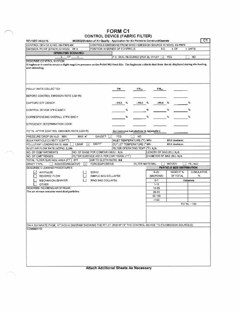
FORM C1CONTROL DEVICE (FABRIC FILTER)
REVISED 09/22/16 NCDEQ/Division of Air Quality - Application for Air Permit to Construct/Operate 1CONTROL DEVICE ID NO: CD-PMFS. BV CONTROLS EMISSIONS FROM WHICH EMISSION SOURCE ID NO(S): ES-PMFS
EMISSION POINT (STACK) ID NO(S): EP-5 POSITION IN SERIES OF CONTROLS NO. 1 OF 1 UNITSWERATING SCENARIO:
P. E. SEAL REQUIRED (PER 2q. 0112)? ^ YES NODESCRIBE CONTROL SYSTEM:A baghouse is used to create a slight negative pressure on the Pellet Mill Feed Silo. The baghouse collects dust from the air displaced during silo loadingand unloading.
POLLUTANTS COLLECTED:
BEFORE CONTROL EMISSION RATE (LB/HR):
CAPTURE EFFICIENCY:
CONTROL DEVICE EFFICIENCY:
CORRESPONDING OVERALL EFFICIENCY:
EFFICIENCY DETERMINATION CODE:
TOTAL AFTER CONTROL EMISSION RATE (LB/HR):
PM PM, PM;
-99.0 % -99.0 % -99.0 % %
% % % %
% % % %
PRESSURE DROP (IN H, 0): MIN:BULK PARTICLE DENSITY (LB/FT3):POLLUTANT LOADING RATE: 0.01INLET AIR FLOW RATE (ACFM): 2, 186NO. OF COMPARTMENTS:NO. OF CARTRIDGES:
MAX: 4"
LB/HR
See Emission CaIculaUons in Appendcc C
GAUGE? -v YES NOINLET TEMPERATURE (°F): MIN
GFVFT OUTLET TEMPERATURE (° MINFILTER OPERATING TEMP (°F): N/A
MAX AmbientMAX Ambient
NO. OF BAGS PER COMPARTMENT: N/AFILTER SURFACE AREA PER CARTRIDGE (FT ;
TOTAL FILTER SURFACE AREA (FT ): 377DRAFT TYPE: INDUCED/NEGATIVEDESCRIBE CLEANING PROCEDURES
B AIR PULSED REVERSE FLOWLJ MECHANICAUSHAKERD OTHER:
DESCRIBE INCOMING AIR STREAM:The air stream contains wood dust particles.
AIR TO CLOTH RATIO: 5.8-- FORCED/POSITIVE
Q SONICD SIMPLE BAG COLLAPSELI RING BAG COLLAPSE
LENGTH OF BAG (IN. ): N/ADIAMETER OF BAG (IN.): N/A
FILTER MATERIAL; WOVEN FELTEDPARTICLE SIZE DISTRIBUTION
SIZE(MICRONS)
D-11-10
10-2525-5050-100>100
WEIGHT % CUMULATIVE
OF TOTAL %
Unknown
TOTAL =100
ON A SEPARATE PAGE, ATTACH A DIAGRAM SHOWING THE RELATIONSHIP OF THE CONTROL DEVICE TO ITS EMISSION SOURCE(S):COMMENTS:
Attach Ad itional Sheets As Necessary

FOKM BSPECIFIC EMISSION SOURCE INFORMATION (REQUIRED FOR ALL SOURCES)
REVISED 09/22/16 NCDEQ/Division of Air Quality - Application for Air Permit to Construct/OperateEMISSION SOURCE DESCRIPTION: EMISSION SOURCE ID NO: ES-CLR1 through ES-CLR6Twelve (12) Pellet Mills and Six (6) Pellet Coolers CONTROL DEVICE ID NO(S): CD-CLR-C1 through CD-CLR-C4,
CD-RCOOPERATING SCENARIO 1 OF EMISSION POINT (STACK) ID NO(S): EP-19DESCRIBE IN DETAILTHE EMISSION SOURCE PROCESS (ATTACH FLOW DIAGRAM):Six [6) pellet coolers (3 existing and 1 new being proposed in this application) follow the twelve (12) pellet mills (10 existing and 2 new beingproposed in this application) to cool the newly formed pellets down to an acceptable storage temperature.
VfPE OF EMISSION SOURCE (CHECK AND COMPLETE APPROPRIATE FORM B1j-B9 ON THE FOLLOWING PAGES):Coal, wood, oil, gas, other burner (Form B1) II Woodworking (Form B4) I Manuf. of chemicals/coatings/inks (Form B7)
[_ Int.combustion engine/generator (Form B2) || Coating/finishing/printing (Form B5) | Incineration (Form B8)Li uid stora e tanks Form B3 Stora e silos/bins Form B6 j Other Form B9
TAR N RU T :
MANUFACTURER-/ MODEL NO.:Bliss (ES-CLR1 through 4), Kahl ES-CLR5)IS THIS SOURCE SUBJECT T NSPS (SUBPARTS?):PERCENTAGE ANNUAL THROUGHPUT (%): DEC-FEB 25%
EXPECTED OP. SCHEDULE: _2d_ HR/DAYNESHAP (SUBPARTS?):
MAR-MAY 25% JUN-AUG 25% SEP-NOV 25%
DAY/WK __52_\NW\
AIR POLLUTANT EMITTEDPARTICULATE MATTER PMPARTICULATE MATTER<10 MICRONS (PMio)PARTICULATE MATTER<2.5 MICRONS (PMss)SULFUR DIOXIDE S02NITROGEN OXIDES (NOx)CARBON MONOXIDE CO)VOLATILE ORGANIC COMPOUNDS (VOCLEADOTHER
HAZARD S MRP
SOURCE 0EMISSIONFACTOR
EXPECTED ACTUAL POTENTIAL EMISSIONS(AFTER CONTROLS / LIMITS) (BEFORE CONTROLS / LIMITS) (AFTER CONTROLS / LIMITS)
Ib/hr tons/yr Ib/hr tons/yr Ib/hr tons/yr
See Emission Calculations in Appendix C
LL
HAZARDOUS AIR POLLUTANT GAS NO.
A
SOURCE 0EMISSIONFACTOR
EXPECTED ACTUAL(AFTER CONTROLS / LIMITS)
Ib/hr tons/yr
NF RTHI URCPOTENTIAL EMISSIONS
(BEFORE CONTROLS / LIMITS) (AFTER CONTROLS / LIMITS)
Ib/hr tons/ r Ib/hr tons/ r
See Emission Calculations in Appendix C
TOXIC AIR POLLUTANT
0 1C IRP LL T NTEMI SIONS INFORM TIONF RT SOU EEXPECTED ACTUAL EMISSIONS AFTER CONTROLS / LIMITATIONS
CASNO. EMISSION Ib/hr Ib/day Ib/yr
See Emission Calculations in Appendix C
Attachments: (1) emissions calculations and supporting documentation; (2) indicate all requested state and federal enforceable permit limits (e. g. hours of operation,emission rates) and describe how these are monitored and with what frequency; and (3) describe any monitoring devices, gauges, or test ports for this source.
Attach Additional Sheets As Necessary

FOR... B9EIVIISSION SOURCE (OTHER)
REVISED 09/22/16 NCDEQ/Division of Air Quality - Application for Air Permit to ConstrucUOperate B9EMISSION SOURCE DESCRIPTION: EMISSION SOURCE ID NO: ES-CLR1 through ES-CLR6Twelve (12) Pellet Mills and six (6) Pellet Coolers ID N ( ): CD-CLR-C1 through CD-CLR-C4,[ES-CLR-1 through ES-CLR-5 are existing - ES-CLR-6 will be new) CD-RCO
OPERATING SCENARIO: 1 OF _1_ EMISSION POINT (STACK) ID NO(S): EP-19DESCRIBE IN DETAIL THE PROCESS (ATTACH FLOW DIAGRAM):Six (6) pellet coolers (5 existing and 1 new being proposed in this application) follow the twelve (12) pellet mills (10 existing and 2 new beingproposed in this application) to cool the newly formed pellets down to an acceptable storage temperature. Similar to the existing pellet cooler 5(ES-CLR-S) and pollutant control configuration, one (1) simple cyclone (CD-CLR-C4) Is being proposed for installation to receive the alrstreamfrom the new pellet cooler (ES-CLR-6). Exhaust from the cyclones (I.e. Pellet Mills and Pellet Coolers) will then be routed to a quench duct and newRTO/RCO (CD-RCO) for further emissions reduction prior to being emitted to the atmosphere. The quench duct is inherent process equipmentrequired for safe operation of the RTO/RCO (i. e., fire prevention) and is not a control device.
MATERIALS ENTERING PROCESS - CONTINUOUS PROCESST»'PE UNITS
Wood Pellets ODT
MAX. DESIGNCAPACIFC (UNIT/HR)
74.8
REQUESTED CAPACITYLIMITATION UNIT/HR)
N A
MATERIALS ENTERING PROCESSTl'PE
BATCH OPERATIONUNITS
MAX. DESIGNCAPACIT>' (UNIT/BATCH
REQUESTED CAPACITYLIMITATION (UNIT/BATCH)
MAXIMUM DESIGN BATCHES / HOUR
REQUESTED LIMITATION (BATCHES / HOUR):
FUEL USED: N AMAX. CAPACITr' HOURLY FUEL USE: N/ACOMMENTS:
(BATCHES/YR):
TOTAL MAXIMUM FIRING RATE MILLION BTU/HR): N AREQUESTED CAPACITl' ANNUAL FUEL USE: N/A
Attach AdcL. ional as Necessary

REVISED 09/22/16
hUKIVI U4CONTROL DEVICE (CYCLONE, MULTICYCLONE, OR OTHER MECHANICAL)
NCDEQ/Division of Air Quality - Application for Air Permit to Construct/OperateCONTROLS EMISSIONS FROM WHICH EMISSION SOURCE ID NO(S): ES.CLR1 through ES-CLR4
POSITION IN SERIES OF CONTROLS NO. 1 OF
CD-CLR-C1 and CD-CLR-C2
EMISSION POINT STACK) ID NO S : EP-19OPERATING SCENARI&
_1 OF _1.DESCRIBE CONTROL SYSTEM :A multicydone (CD-CLR-C1) controls emissions from four (4) pellet mills and two (2) pellet coolers (ES-CLR1 and 2), a second multicyclone (CD-CLR-CZ) alsocontrols emissions from four (4) pellet mills and two (Z) pellet coolers (ES-CLR3 and 4) . The exhaust from the two (2) multicyclones will be routed to a quenchduct and new RTO/RCO (CD-RCO] for VOC/HAP reduction prior to being emitted into the atmosphere. The quench duct will be inherent process equipmentrequired for safe operation of the RTO/RCO (i.e., flre prevention) and is not a control device.
P. E. SEAL REQUIRED (PER 2Q.0112)? B YES
2 UNITS
n NO
PM PM, PM,PQLLUTANT(S) COLLECTED:
BEFORE CONTROL EMISSION FiATE (LB/HR):
CAPTURE EFFICIENCY:
CONTROL DEVICE EFFICIENCY:
CORRESPONDING OVERALL EFFICIENCY:
EFFICIENCY DETERMINATION CODE;
TOTAL AFTER CONTROL EMISSION RATE (LB/HR)
PRESSURE DROP (IN. H^O): _ MIN
INLET TEMPERATURE (°F): MIN
.MAX
MAX OUTLET TEMPERATURE (°F): MIN
INLET AIR FLOW RATE (ACFM): 13, 750 per cooler 55, 000 total BULK PARTICLE DENSITY (LB/FT3 : 3E-06POLLUTANT LOADING RATE GR/FT3 :
90+ % 90+ % 90+
% %
% %
See Emission Calculations in Appendbc C
%
%
%
%
%
%
MAX
SETTLING CHAHBBl
LENGTH INCHES:
WIDTH (INCHES :HEIGHT INCHES :
VELOCITY (FT/SEC. :
NO. TRAYS:
NO. BAFFLES:
CYCLONE
INLET VELOCITY FT/SEC :DIMENSIONS INCHES See instructions
H: Dd:W: Lb:
De: Lc:
D: S:TYPE OF CYCLONE D CONVENTIONAL
DESCRIBE MAINTENANCE PROCEDURES:
dlRCULARD RECTANGLEIF WET SPRAY UTILIZED
LIQUID USED:
FLOW RATE (GPM):
MAKE UP RATE GPM :
B HIGH EFFICIENCY
Periodic inspection of mechanical integrity during plant outages as specified by the gi^-^manufacturer.
DESCRIBE INCOMING AIR STREAM:Combined exhaust from pellet i: mills and pellet coolers
(MICRONS)0-1
1-10
10-25
25-50
50-100>100
MULTICYCLONE
NO. TUBES: 2
DIAMETER OF TUBES: 43"
HOPPER ASPIRATION SYSTEM?D YES B NO
LOUVERS?
D YES 0 NOD OTHER
PARTICLE SIZE USTRIKJTIONWEIGHT % CUMULATIVEOF TOTAL %
Unknown
TOTAL =100
DESCRIBE ANY MONITORING DEVICES, GAUGES, TEST PORTS, ETC:N/A
SEPARATE PAGE, ATTACH A DIAGRAM OF THE RELATIONSHIP OF THE CONTROL DEVICE TO ITS EMISSION SOURCE S :
Attach Additional Sheets As Necessary

hUKIVI U4CONTROL DEVICE (CYCLONE, MULTICYCLONE, OR OTHER MECHANICAL)
REVISED 09/22/16
CD-CLR-C3 andCD-CLR-C4
NCDEQ/Division of Air Quality - Application for Air Permit to Construct/OperateCONTROLS EMISSIONS FROM WHICH EMISSION SOURCE ID NO(S): ES-CLRS and ES-CLR6
POSITION IN SERIES OF CONTROLS NO. 1 OF 2 UNITS
P.E. SEAL REQUIRED (PER 2Q.0112)? E YES D NO
EMISSION POINT (STACK) ID NO(S): EP-19OPERATING SCENARICfc
_1_OF_1_DESCRIBE CONTROL SYSTEM :One [1] simple cyclone (CD-CLR-C3) controls emissions from two (2) pellet mills and one (1) pellet cooler (ES-CLRS). As part of this project Enviva is proposingto install two (2) new pellet mills and one new pellet cooler (ES-CLR6) thatwill be controlled by a new simple cyclone (CD-CLR-C4). The exhaust from the two (2)simple cyclones will be routed to a quench duct and new RTO/RCO (CD-RCO) for VOC/HAP reduction prior to being emitted into the atmosphere. The quenchduct will be inherent process equipment required for safe operation of the RTO/RCO (i.e., flre prevention) and is nota control device.
POLLUTANT(S) COLLECTED:
BEFORE CONTROL EMISSION RATE (LB/HR):
CAPTURE EFFICIENCY:
CONTROL DEVICE EFFICIENCY:
CORRESPONDING OVERALL EFFICIENCY:
EFFICIENCY DETERMINATION CODE:
TOTAL AFTER CONTROL EMISSION RATE (LB/HR):
PRESSURE DROP (IN. N20): _ MIN
INLET TEMPERATURE (°F): _ MIN
PM PM, PM,.
90+ % 90+ ' 90+ %
See Emission Calculations in Appendcc C
.MAX
^AmlaenLMAX OUTLET TEMPERATURE (°F): MINBULK PARTICLE DENSITY (LB/FT3): 3E.06
MAX
INLET AIR FLOW RATE ACFM): 13, 750POLLUTANT LOADING RATE GR/FT3 :
SETTUNG CHAMBER CYCl.ONE MULTICYCLONE
LENGTH INCHES : INLET VELOCITY FT/SEC : D;IRCULAR D RECTANGLE NO. TUBES:WIDTH INCHES: DIMENSIONS (INCHES) See instructions IF WET SPRAY UTILIZED DIAMETER OF TUBES:
HEIGHT INCHES: H: Dd: LIQUID USED:
VELOCITY (FT/SEC. ): W: Lb: FLOW RATE GPM):NO. TRAYS: De: Lc: MAKE UP RATE (GPM):
NO. BAFFLES: D: S:TYPE OF CYCLONE D CONVENTIONAL E HIGH EFFICIENCY
DESCRIBE MAINTENANCE PROCEDURES:Periodic inspection of mechanical integrity during plant outages as specifled by themanufacturer.
DESCRIBE INCOMING AIR STREAM:Combined exhaust from pellet mills and pellet coolers
SIZE(MICRONS)
0-1
1-10
10-25
25-50
50-100
>100
HOPPER ASPIRATION SYSTEM?
D YES D NOLOUVERS?D YES D NOD OTHER
PARTICLE SIZE DISTRIBUTIONWEIGHT % CUMULATIVEOF TOTAL %
Unknown
TOTAL =100
DESCRIBE ANY MONITORING DEVICES, GAUGES, TEST PORTS, ETC:N/A
A SEPARATE PAGE, ATTACH A DIAGRAM OF THE RELATIONSHIP OF THE CONTROL DEVICE TO ITS EMISSION SOURCE S
Attach Additional Sheets As Necessary

FOKM C3CONTROL DEVICE (THERMAL OR CATALYTIC)
REVISED 09/22/16 NCDEQ/Division of Air Quality - Application for Air Permit to Construct/OperateAS REQUIRED BY ISA NCAC 2Q .0112, THIS FORM MUST BE SEALED BY A PROFESSIONAL ENGINEER (P.E.) UCENSED 1 NORTH CAROLINA.
CONTROL DEVICE ID NO: CD-RCO
EMISSION POINT (STACK) ID NO(S): EP-19
CONTROLS EMISSIONS FROM WHICH EMISSION SOURCE ID NO(S): ES-CLR-1 throu ES-CLR-6, ES-DSHM
POSITION IN SERIES OF CONTROLS
POSITION IN SERIES OF CONTROLSPOSITION IN SERIES OF CONTROLS
MODEL NO: TBD
UNITS (ES-CLR-lthrou
UNITS ES-DSHMUNITS (ES-DWDS)
-7
MANUFACTURER:TBDOPERATING SCENARIO:
TYPE AFTERBURNER REGENERATIVE THERMAL OXIDATION Q RECUPERATIVE THERMAL OXIDATION 0 CATALYTIC OXIDATIONEXPECTED LIFE OF CATALYST (YRS): METHOD OF DETECTING WHEN CATALYST NEEDS REPLACMENT:CATALYST MASKING AGENT IN AIR STRI HALOGEN SILICONE PHOSPHOROUS COMPOUND _ HEAVY METAL
D SULFUR COMPOUND B OTHER SPECIFY TBD U NONETYPE OF CATALYST: TBD CATALYST VOL (FT3): TBD VELOCITY THROUGH CATALYST (FPS): TBDSCFM THROUGH CATALYST: TBDEmissions from the Pellet Coolers (ES-CLR-1 thru ES-CLR-7) are routed to the pellet cooler cyclones (CD-CLR-C1 through CD-CLR-C4) and then to a quench duct and the newRTO/RCO (CD-RCO). Emissions from the Dry Shavings Hammermill (ES-DSHM) are routed to a cyclone (CD-DSHM-C) and to the Dried Wood Day Silo (ES-DWDS). Emissionfrom the Dried Wood Day Silo (ES-DWDS) are routed through a bin vent (CD-DWDS-BV) and then to a quench duct and the new RTO/RCO
POLLUTANT(S) COLLECTED;
BEFORE CONTROL EMISSION RATE (LB/HR);
CAPTURE EFFICIENCY:
CONTROL DEVICE EFFICIENCY:
CORRESPONDING OVERALL EFFICIENCY:EFFICIENCY DETERMINATION CODE;TOTAL AFTER CONTROL EMISSION RATE (LB/HR):
PRESSURE DROP (IN. H C MIN MAX TBDINLET TEMPERATURE (°F MIN MAXTBD
INLET AIR FLOW RATE (ACFM): TBD SCFM : TBD
COMBUSTION CHAMBER VOLUME (FT3): TBD% EXCESS AIR: TBD
AUXILIARY FUEL USED: Natural GasDESCRIBE MAINTENANCE PROCEDURES:TBD
voc
9S
%
See Emission Calculations in A endix C
OUTLET TEMPERATURE (°F): TBD MIN TBD MAX
RESIDENCE TIME (SECONDS): TBD
COMBUSTION TEMPERATURE (°F): TBDINLET MOISTURE CONTENT (%): TBDCONCENTRATION mv) TBD INLET TBD OUTLETTOTAL MAXIMUM FIRING RATE (MILLION BTU/HR): 20
DESCRIBE ANY AUXILIARY MATERIALS INTRODUCED INTO THE CONTROL SYSTEM:N/A
COMMENTS:
s cessary

FORM BSPECIFIC EMISSION SOURCE INFORMATION (REQUIRED FOR ALL SOURCES)
REVISED 09/22/1 f NCDEQ/Division of Air Quality - Application for Air Permit to Construct/OperateEMISSION SOURCE DESCRIPTION:Finished Product Handling, Truck Loadout Bin, Pellet Loadouts EMISSION SOURCE ID NO: ES-FPH, ES-TLB, ES-PL1 and ES-PL2
CONTROL DEVICE ID NO(S): CD-FPH-BFOPERATING SCENARIO 1 OF EMISSION POINT STACK ID NO S): EP-9DESCRIBE IN DETAILTHE EMISSION SOURCE PROCESS (ATTACH FLOW DIAGRAM):Following the pellet coolers, pellets are conveyed to finished product handling (ES-FPH) where the Hnal product is conveyed across a pelletscreener, onto a collection conveyor, and then to a bucket elevator where it is dropped through pipe chutes onto a belt that feeds the truckloadout bin (ES-TLB). From the bin, pellets are gravity fed onto two (2) transfer belts per loading station which transfer pellets to a shuttlebelt that drops pellets into trucks through two (2)covered chutes (ES-PL1 and ES-PL2). Finished product handling (ES-FPH], truck loadout bin(ES-TLB), and pellet loadout (ES-PL1 and ES-PL2) emissions are vented into the finished product handling baghouse (CD-FPH-BF) as a fireprevention measure to prevent any build-up of dust on surfaces within the finished product handling building. Fines from the finished producthandling baghouse [CD-FPH-BF) are directed through an air lock to the high pressure blow line [HPBL] and pneumatically transferred to thefines bin (ES-FB) which is controlled by a separate baghouse (CD-FB-BV). Collected fines are relntroduced into the pellet producUon process.
FfPE OF EMISSION SOURCE (CHECK AND COMPLETE APPROPRIATE FORM BTB9 ON THE FOLLOWING PAGES):L Coal, wood, oil, gas, other burner (Form B1) D Woodworking (Form B4) C Manuf. of chemicals/coatings/inks (Form B7)\Z. lnt. combustionengine/generator(FormB2) Q Coating/finishing/printing (Form B5) |_ Incineration (Form 88)
Li uid stora e tanks Form B3 . / Stora e silos/bins Form 86 ^ Other Form B9
MANUFACTURER / MODEL NO.:Aircon Model # 13. 6 RAW 268-10IS THIS SOURCE SUBJECT . ^_ NSPS SUBPARTS?):PERCENTAGE ANNUAL THROUGHPUT %: DEC-FEB 25%
EXPECTED OP. SCHEDULE: 24 HR/DAYNESHAP (SUBPARTS?):
MAR-MAY 25% JUN-AUG 23% SEP-NOV 25%
DAY/WK 52 WKA'
AIR POLLUTANT EMITTEDPARTICULATE MATTER (PM)PARTICULATE MATTER<10 MICRONS (PM, o)PARTICULATE MATTER<2. 5 MICRONS (PMzs)SULFUR DIOXIDE (S02)NITROGEN OXIDES (NOx)CARBON MONOXIDE (CO)VOLATILE ORGANIC COMPOUNDS (VOC)LEADOTHER
/ POL
SOURCE 0 EXPECTED ACTUALEMISSION (AFTER CONTROLS/LIMITS)FACTOR Ib/hr tons/yr
POTENTIAL EMISSIONS(BEFORE CONTROLS / LIMITS) (AFTER CONTROLS / LIMITS)
Ib/hr tons/ r Ib/hr tons/yr
See Emission Calculations in Appendix C
HAZARDOUS AIR POLLUTANT
TANTEMI SION NFO TIO F RTHISOURCE 0 EXPECTED ACTUAL POTENTIAL EMISSIONSEMISSION (AFTER CONTROLS/LIMITS) (BEFORE CONTROLS / LIMITS) (AFTER CONTROLS / LIMITS)
CAS NO. FACTOR Ib/hr tons/ r Ib/hr tons/yr Ib/hr tons/ r
N/A
TOXCAI
TOXIC AIR POLLUTANT
NT EM S IONS INF Tl N FOR TH S CEEXPECTED ACTUAL EMISSIONS AFTER CONTROLS / LIMITATIONS
Ib/hr Ib/day Ib/ r
LL
OFGAS NO. EMISSION
N/A
Attachments: (1) emissions calculations and supporting documentation; (2) indicate all requested state and federal enforceable permit limits (e.g. hours of operation,emission rates) and describe how these are monitored and with what frequency; and (3) describe any monitoring devices, gauges, or test ports for this source.
Attach Additional Sheets As Necessary

hUKIVI B6ERfllSSION SOURCE (STORAGE SILO/BINS)
REVISED 09/22/16 NCDEQ/Division of Air Quality - Application for Air Permit to Construct/Operate B6EMISSION SOURCE DESCRIPTION: EMISSION SOURCE ID NO: ES-TLBTruck Loadout Bin CONTROL DEVICE ID NO(S : CD-FPH-BFOPERATING SCENARIO: 1 OF EMISSION POINT STACK) ID NO S): EP-9
DESCRIBE IN DETAIL THE PROCESS (ATTACH FLOW DIAGRAM):Final product is conveyed to the truck loadout bin (ES-TLB) that feeds the pellet loadout (ES-PL1 and ES-PL2). Emissions are controlled by thefinished product handling baghouse (CD-FPH-BF).
MATERIAL STORED: Pellets
CAPACITY CUBIC FEET:
DIMENSIONS (FEET HEIGHT:ANNUAL PRODUCT THROUGHPUT (TONS)
PNEUMATICALLY FILLED
BLOWERD COMPRESSORD OTHER:
BDD
TONS:
DIAMETER: (OR) LENGTH;ACTUAL: MAXIMUM
MECWNICALLY FILLED
SCREW CONVEYOR
BELT CONVEYOR
BUCKET ELEVATOR
OTHER:
WIDTH: HEIGHT:
DESIGN CAPACITY 630,000 ODT
DDE
FILLED FRCNUI
RAILCARTRUCK
STORAGE PILE
OTHER: Conveyor
NO. FILL TUBES:MAXIMUM ACFM: 7SO eachMATERIAL IS UNLOADED TO:
BY WHAT METHOD IS MATERIAL UNLOADED FROM SILO?
MAXIMUM DESIGN FILLING RATE OF MATERIAL (TONS/HR):
MAXIMUM DESIGN UNLOADING RATE OF MATERIAL (TONS/HR):
COMMENTS:
Attach As Necessary
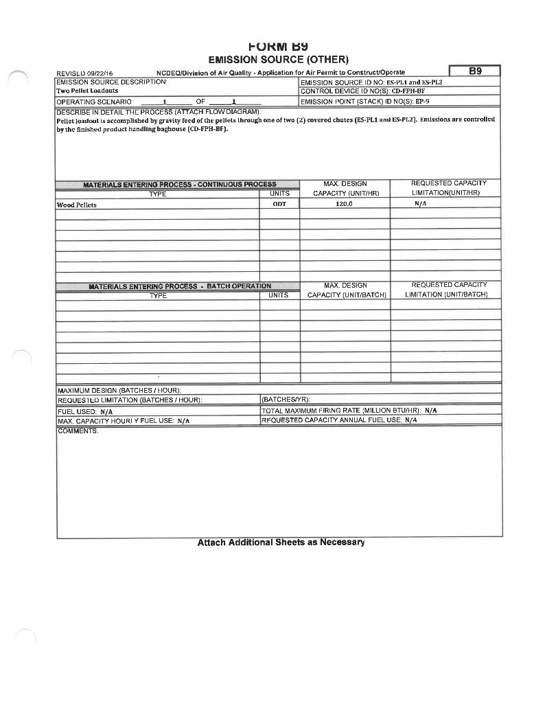
hUKivi yyEMISSION SOURCE (OTHER)
REVISED 09/22/16 NCDEQ/Division of Air Quali - Application for Air Permit to ConstrucVOperate B9EMISSION SOURCE DESCRIPTION: EMISSION SOURCE ID NO: ES-PL1 and ES-PL2Two Pellet Loadouts CONTROL DEVICE ID NO(S): CD-FPH-BF
OPERATING SCENARIO: 1 OF 1 _ EMISSION POINT (STACK) ID NO(S): EP-9
DESCRIBE IN DETAIL THE PROCESS (ATTACH FLOW DIAGRAM):Pellet loadout is accomplished by gravity feed of the pellets through one of two (2) covered chutes (ES-PL1 and ES-PL2). Emissions are controlledby the Hnished product handling baghouse (CD-FPH-BF).
MATERIALS ENTERING PROCESS - CONTINUOUS PROCESSTYPE UNITS
Wood Pellets ODT
MAX. DESIGNCAPACITf (UNIT/HR)
120.0
REQUESTED CAPACITYLIMITATION(UNIT/HR)
N/A
MATERIALS ENTERING PROCESS - BATCH OPERATIONTl'PE UNITS
MAX. DESIGN
CAPACITY (UNIT/BATCH)REQUESTED CAPACITf
LIMITATION (UNIT/BATCH)
MAXIMUM DESIGN (BATCHES / HOUR):REQUESTED LIMITATION (BATCHES / HOUR):
FUEL USED: N/AMAX. CAPACITY HOURLY FUEL USE: N/ACOMMENTS:
(BATCHES/YR):
TOTAL MAXIMUM FIRING RATE (MILLION BTU/HR): N/AREQUESTED CAPACITY ANNUAL FUEL USE: N/A
Attach Additional Sheets as Necessary

FORM B9EIVIISSION SOURCE (OTHER)
REVISED 09/22/16 NCDEQ/Division of Air Quali - Application for Air Permit to Construct/Operate B9EMISSION SOURCE DESCRIPTION: EMISSION SOURCE ID NO: ES-FPH
Finished Product Handling CONTROL DEVICE ID NO(S): CD-FPH-BFOPERATING SCENARIO: 1 OF 1 _ EMISSION POINT (STACK) ID NO(S): EP-9DESCRIBE IN DETAIL THE PROCESS (ATTACH FLOW DIAGRAM):Collection of transfer points, pellet screening operations, and pellet conveying. Emissions are controlled by the finished product handlingbaghouse (CD-FPH-BF).
MATERIALS ENTERING PROCESS - CONTINUOUS PROCESSTCPE UNITS
Wood Pellets ODT
MAX. DESIGNCAPACITl' (UNIT/HR)
120.0
REQUESTED CAPACITY
LIMITATION(UNIT/HR)N A
MATERIALS ENTERING PROCESSTYPE
BATCH OPERATIONUNITS
MAX. DESIGN
CAPACITY UNIT/BATCH)REQUESTED CAPACITY
LIMITATION (UNIT/BATCH)
MAXIMUM DESIGN (BATCHES / HOUR):REQUESTED LIMITATION BATCHES / HOUR
FUEL USED: N AMAX. CAPACITl' HOURLY FUEL USE; N/ACOMMENTS:
(BATCHES/YR):
TOTAL MAXIMUM FIRING RATE (MILLION BTU/HR): N/AREQUESTED CAPACITf ANNUAL FUEL USE: N/A
Attach Additional Sheets as Necessary

FORIM C1CONTROL DEVICE (FABRIC FILTER)
REVISED 09/22/16 NCDEQ/Division of Air Quality - Application for Air Permit to ConstrucUOperate 1CONTROLS EMISSIONS FROM WHICH EMISSION SOURCE ID NO(S): ES-FPH, ES-TLB, ES-PL1 and
CONTROL DEVICE ID NO: CD-FPH-BF ES-PLZ
EMISSION POINT (STACK) ID NO(S): EP-9 POSITION IN SERIES OF CONTROLS NO. 1 OF 1 UNITSWERATING SCENARIO:
P. E. SEAL REQUIRED (PER 2q . 0112)? ^ YES NO
DESCRIBE CONTROL SYSTEM:A baghouse controls PM emissions from the finished product handling conveyors and screens, as well as the pellet loadout operation consisting of loadingHnished product from the Pellet Loadout Bins into trucks.
POLLUTANTS COLLECTED:
BEFORE CONTROL EMISSION RATE (LB/HR):
CAPTURE EFFICIENCY:
CONTROL DEVICE EFFICIENCY:
CORRESPONDING OVERALL EFFICIENCY:
EFFICIENCY DETERMINATION CODE:
TOTAL AFTER CONTROL EMISSION RATE (LB/HR):
PRESSURE DROP (IN HzO): MIN: MAX: 6"
PM PM,
-99.0 % -99.0 % ~99.0 %
% % %
%
GAUGE?
BULK PARTICLE DENSITY (LB/FT ): 1.43E-06POLLUTANT LOADING RATE: 0.01 Q LB/HR ^ GR/FTINLET AIR FLOW RATE (ACFM): 35, SOONO. OF COMPARTMENTS: 1 NO. OF BAGS PER COMPARTMENT:NO. OF CARTRIDGES: FILTER SURFACE AREA PER CARTRIDGE (FT2;TOTAL FILTER SURFACE AREA (FT ): 4, 842DRAFT TYPE: INDUCED/NEGATIVE ^DESCRIBE CLEANING PROCEDURES
0 AIR PULSE Q|_] REVERSE FLOW QD MECHANICAUSHAKER DD OTHER:
DESCRIBE INCOMING AIR STREAM:The air stream contains wood dust particles.
See Emission Calculations in Appendix C
YES NOINLET TEMPERATURE (°F): MINOUTLET TEMPERATURE (° MINFILTER OPERATING TEMP (°F):
MAX 120° FMAX 100'F
LENGTH OF BAG (IN. ): 144DIAMETER OF BAG (IN. ): 4, 842
AIR TO CLOTH RATIO: 7.30FORCED/POSITIVE
SONICSIMPLE BAG COLLAPSE
RING BAG COLLAPSE
FILTER MATERIAL:PAI
SIZE(MICRONS)
0-11-1010-2525-5050-100>100
WOVEN ./ FELTEDPARTICLE SIZE DISTRIBUTION
WEIGHT % CUMULATIVEOF TOTAL %
Unknown
TOTAL =100
ON A SEPARATE PAGE, ATTACH A DIAGRAM SHOWING THE RELATIONSHIP OF THE CONTROL DEVICE TO ITS EMISSION SOURCE(S):COMMENTS:
Attach Additional Sheets As Necessary

FOKIVI BSPECIFIC EMISSION SOURCE INFORMATION (REQUIRED FOR ALL SOURCES)
REVISED 09/22/1 i NCDEQ/Division of Air Quality - Application for Air Permit to ConstrucUOperateEMISSION SOURCE DESCRIPTION: EMISSION SOURCE ID NO: ES-FBFines Bin CONTROL DEVICE ID NO(S): CD-FB-BVOPERATING SCENARIO OF 1 EMISSION POINT (STACK) ID NO(S): EP-8DESCRIBE IN DETAILTHE EMISSION SOURCE PROCESS (ATTACH FLOW DIAGRAM):Fine pellet material from Finished Product Handling [ES-FPH] is collected by the Fines System and conveyed to the Fines Bin (ES-FB) which iscontrolled by a baghouse [CD-FB-BV).
TYPE OF EMISSION SOURCE (CHECK AND COMPLETE APPROPRIATE FORM B1^9 ON THE FOLLOWING PAGES):L Coal, wood, oil, gas, other burner (Form B1) D Woodworking (Form 84) C Manuf. of chemicals/coatings/inks (Form B7)^_ Int.combustion engine/generator (Form B2) D Coating/finishing/printing (Form B5) |_ Incineration (Form B8)
Li uid stora e tanks Form B3 -/ Stora e silos/bins Form B6 Other Form B9TART N U Tl A : DATE MANUFA TURED:
MANUFACTURER / MODEL NO.:Aircon CAR 36-6IS THIS SOURCE SUBJECT . NSPS(SUBPARTS?PERCENTAGE ANNUAL THROUGHPUT %): DEC-FEB 25%
EXPECTED OP. SCHEDULE: HR/DAYNESHAP (SUBPARTS?):
MAR-MAY 25% JUN-AUG 2R% SEP-NOV 25%
DAY/WK _£2_WKA'
AIR POLLUTANT EMITTEDPARTICULATE MATTER PM)PARTICULATE MATTER<10 MICRONS (PM, o)PARTICULATE MATTER<2. 5 MICRONS (PMzs)SULFUR DIOXIDE (S02)NITROGEN OXIDES (NOx)CARBON MONOXIDE (CO)VOLATILE ORGANIC COMPOUNDS (VOC)LEADOTHER
A OUSA
SOURCE 0 EXPECTED ACTUAL POTENTIAL EMISSIONSEMISSION (AFTER CONTROLS / LIMITS) (BEFORE CONTROLS/LIMITS) (AFTER CONTROLS / LIMITS)FACTOR Ib/hr tons/yr Ib/hr tons/yr Ib/hr tons/yr
See Emission Calculations in Appendix C
HAZARDOUS AIR POLLUTANT
POLLUT NTEMIS I NS I OR ATI NF HI OU CSOURCE 0 EXPECTED ACTUAL POTENTIAL EMISSIONSEMISSION (AFTER CONTROLS / LIMITS) (BEFORE CONTROLS/LIMITS) (AFTER CONTROLS / LIMITS)
CAS NO. FACTOR Ib/hr tons/yr Ib/hr tons/ r Ib/hr tons/yr
N/A
TOXIC AIR POLLUTANT
T Xl IR 0 AN EMISSION FO MAT 0 F R IS S UR EEXPECTED ACTUAL EMISSIONS AFTER CONTROLS / LIMITATIONS
CASNO. EMISSION Ib/hr Ib/day Ib/yr
N/A
Attachments: (1) emissions calculations and supporting documentation; (2) indicate all requested state and federal enforceable permit limits (e. g. hours of operation,emission rates) and deschbe how these are monitored and with what frequency; and(3)descnbe any monitoring devices, gauges, or test ports for this source.
Attach Additional Sheets As Necessary

hUKIVI BbEMISSION SOURCE (STORAGE SILO/BINS)
REVISED 09/22/16 NCDEQ/Division of Air Quality - Application for Air Permit to Construct/Operate B6EMISSION SOURCE DESCRIPTION: EMISSION SOURCE ID NO: ES-FB
Fines Bin CONTROL DEVICE ID NO(S): CD-FB-BVOPERATING SCENARIO: OF 1 EMISSION POINT(STACK) ID NO S : EP-8
DESCRIBE IN DETAIL THE PROCESS (ATTACH FLOW DIAGRAM):Fines from Finished Product Handling (ES-FPH] are collected by the Fines System and conveyed to the Fines Bin (ES-FB) which is controlled by abaghouse (CD-FB-BV).
MATERIAL STORED: Wood Fines
CAPACIFf CUBIC FEET: 2,200
DIMENSIONS FEET) HEIGHT: 97. 3 DIAMETER: 12ANNUAL PRODUCT THROUGHPUT (TONS) ACTUAL:
PNEtfflflATICALLY FILLED./ BLOWERD COMPRESSOR
OTHER:
(OR)
DENSITY OF MATERIAL (LB/FT3): 40TONS:
LENGTH: WIDTH: HEIGHT:
MAXIMUM DESIGN CAPACITY: 31,500 ODT
DDa
MECHANICALLY FILLED
SCREW CONVEYORBELT CONVEYOR
BUCKET ELEVATOR
OTHER:
FILLED FROM
RAILCAR
D TRUCKD STORAGE PILEE] OTHER: Finished Product Handlin
NO. FILL TUBES:MAXIMUM ACFM: 750 each
MATERIAL IS UNLOADED TO:
BY WHAT METHOD IS MATERIAL UNLOADED FROM SILO?
MAXIMUM DESIGN FILLING RATE OF MATERIAL (TONS/HR):
MAXIMUM DESIGN UNLOADING RATE OF MATERIAL (TONS/HR):
COMMENTS:
Attach Additional Sheets As Necessary

FORM C1CONTROL DEVICE (FABRIC FILTER)
REVISED 09/22/16 NCDEQ/Division of Air Quality - Application for Air Permit to Construct/Operate
CONTROL DEVICE ID NO: CD-FB-BV CONTROLS EMISSIONS FROM WHICH EMISSION SOURCE ID NO(S): ES-FBEMISSION POINT (STACK) ID NO(S): EP-B POSITION IN SERIES OF CONTROLS NO. 1 OF 1 UNITS
OPERATING «;ENARIO:P. E. SEAL REQUIRED (PER 2q.0112)? ^ YES NO
DESCRIBE CONTFiOL SYSTEM:Fines from Finished Product Handling (ES-FPH) are collected by the Fines System and conveyed to the Fines Bin (ES-FB) which is controlled by a baghouse(CD-FB-BV).
POLLUTANTS COLLECTED:
BEFORE CONTROL EMISSION RATE (LB/HR):
CAPTURE EFFICIENCY:
CONTROL DEVICE EFFICIENCY:
CORRESPONDING OVERALL EFFICIENCY:
EFFICIENCY DETERMINATION CODE:
TOTAL AFTER CONTROL EMISSION RATE (LB/HR):
PM PM, PM;
-99.0 % -99.0 % -99.0 %
%
PRESSURE DROP (IN HzO); MIN: MAX: TBD GAUGE?BULK PARTICLE DENSITY (LB/FT3): 3. 14E-06POLLUTANT LOADING RATE: 0.01 LB/HR -v GR/FTINLET AIR FLOW RATE (ACFM): 3,600
NO. OF COMPARTMENTS: NO. OF BAGS PER COMPARTMENT: N/ANO. OF CARTRIDGES: FILTER SURFACE AREA PER CARTRIDGE (FT2):
See Emission Calculations in Appendfai C
YES NOINLET TEMPERATURE (°F): MINOUTLET TEMPERATURE (° MINFILTER OPERATING TEMP (°F): N/A
MAX AmbientMAX Ambient
LENGTH OF BAG (IN. ): N/ADIAMETER OF BAG (IN.): N/A
TOTAL FILTER SURFACE AREA (FT'): 325DRAFT TYPE: -' INDUCED/NEGATIVE QDESCRIBE CLEANING PROCEDURES
E AIR PULSE DD REVERSE FLOW DD MECHANICAI-/SHAKER LJD OTHER:
DESCRIBE INCOMING AIR STREAM:The air stream contains wood dust particles.
AIR TO CLOTH RATIO: 11.08FORCED/POSITIVE
SONICSIMPLE BAG COLLAPSE
RING BAG COLLAPSE
FILTER MATERIAL: WOVEN FELTEDPARTICLE SIZE DISTRIBUTION
SIZE(MICRONS)
0-11-10
10-2525-5050-100>100
WEIGHT % CUMULATIVEOF TOTAL %
Unknown
TOTAL =100
ON A SEPARATE PAGE, ATTACH A DIAGRAM SHOWING THE RELATIONSHIP OF THE CONTROL DEVICE TO ITS EMISSION SOURCE(S):COMM NTS:
Attac Additional heets As Necessary

APPENDIX ECAM PLANS

Compliance Assurance Monitoring
Enviva Pellets Ahoskie, LLC
Dry Hammermills 1 through 7 (ES-DHM-1 through ES-DHM-7)
Back round
A. Emissions Unit
Description:Identification:
Facility:
Dry Hammermills 1 through 7ES-DHM-1 through ES-DHM-7Enviva Pellets Ahoskie, LLC
Ahoskie, Hertford County, NC
B. A licable Re ulation Emission Limit and Monitorin Re uirements
ISA North Carolina Administrative Code (NCAC) 02D. 0515
47. 7 Ib/hrVisible emissions, WESP secondary voltage and current
Regulation No.:
Emission limits:
Particulate matter:
Monitoring requirements:
C. Control Technolo
Wet Electrostatic Precipitator (CD-WESP)
Monitoring Approach
The key elements of the monitoring approach are presented in Table 1 below.

Table 1. Monitoring Approach for Dry Hammermills 1 through 7
Indicator
Measurement Approach
I. Indicator Range
II, Performance Criteria
A. Data Representativeness
B. Verification of OperationalStatus
C. QA/QC Practices andCriteria
D Monitoring Frequency
E. Data Collection Procedure
Visible emissions
Visible emissions will be monitored weekly using EPAReference Method 22 procedures.
Visible emissions above normal determined inaccordance with Reference Method 22, triggerenhanced monitoring, or corrective action.1
Visible observations will be made at the emission
point to the atmosphere [at the outlet of the RTO(CD-RTO)].
NA
The observer will be familiar with Reference Method22 and follow Method 22 procedures.
A 6-minute Method 22 observation will be performedweekly.
The visible emissions observation will bedocumented by the observer and records of theobservation will be retained for five ears.
Secondary Voltage and Current
Continuous monitoring of secondary voltage and currentthrough the precipitator using a voltmeter/ammeter andaveraged daily.
An excursion is defined as a daily average measurementthat is below 20 kV secondary voltage or 200 mAsecondary current.
Voltmeter/ammeter installed per manufacture'sspecifications.
Operation verified during observation.
Confirm the voltmeter and ammeter read zero when theunit is not operating. Calibrate units annually. Annualinternal inspection of the WESP including visual checks forcritical components, checks for any equipment that doesnot alarm when de-energized to ensure it is operational,and re lacement of broken e ui ment as necessar .
Secondary voltage and current through the precipitatorare monitored continuously.
Average secondary voltage and current through theprecipitator are recorded daily, and records will beretained for five ears.
F. Averaging Period Observation period not less than 6 minutes. Daily Average.If visible emissions that are not normal are observed using Reference Method 22, EPA Reference Method 9 can be used to determine compliance with the 20% opacity limitor corrective action may be taken.

Justification
A. Back round
The pollutant-specific emissions units are the Dry Hammermills (ES-DHM-1 through ES-DHM-7)and the regulated pollutant is particulate matter (PM). ES-DHM-1 through ES-DHM-7 vent to aproduct recovery cyclone that is routed to one of three (3) baghouses (CD-DHM-FF1 through CD-DHM-FF3) for particulate matter control. An air flow recirculation process will be implementedto route a portion of the exhaust from each dry hammermill cyclone back into the front end ofthe respective dry hammermill to reduce fresh intake air and thus decrease the volume of airthat is routed to the downstream control devices. The reduced dry hammermill exhaust will berouted to baghouses, followed by a quench duct and then to either the dryer furnace (ES-DRYER), the dryer WESP (CD-WESP), or a combination of the two, before entering the RTO (CD-RTO). Interlocks will be installed to cease operation of the dry hammermills if a minimum flowrate is not maintained in the quench duct or if the furnace/WESP/RTO system ceases normaloperation.
At all times 100% of the dry hammermill exhaust will be controlled by a baghouse, WESP, andRTO. The furnace is not a control device. The WESP will provide a reduction in PM and metallichazardous air pollutant (HAP) and the RTO will provide a reduction in VOC and organic HAP/TAPemissions. The highest pollutant inlet loading to the control devices will occur when the furnaceand dryer are operating at maximum capacity with all dry hammermill exhaust routed to theinlet of the furnace. The quench system is considered inherent process equipment that isrequired to safely operate the RTO (i.e., reduce fire risk) and is not a control device. It should benoted that upon implementation of the proposed dry hammermill recirculation the baghouseswill not be required to achieve compliance with the PM emission limit under ISA NCAC 02D. 0515. Although PM emissions will still be controlled by the baghouses, control by the WESP willresult in sufficient reduction to ensure compliance with the PM emission limit.
B. Rationale for Selection of Performance Indicators
The following parameters will be monitored:
Visible emissions at RTO outlet
ii. WESP Secondary Voltage and Current
Visible emissions is selected as one of the performance indicators that ensure proper operationof the control device (WESP) so that compliance with the ISA NCAC02D.0515 ParticulateMatter emission limit is achieved. Visible emissions are relatively easy to monitor and is a goodindicator of performance changes in particulate matter control devices. Visible emissionobservations using Reference Method 22 is an acceptable indicator used to ensure compliancewith many NSPS regulations.
Secondary voltage and current are also selected as indicators for WESP performance. Secondaryvoltage and current are used to measure the power input to the WESP and are recommendedparameters by WESP manufactures in evaluating performance and proper operation of a WESP.

C. Rationale for Selection of Indicator Ran es
Visible emission observations at the outlet of the RTO (CD-RTO) are performed weekly using EPAReference Method 22 procedures. Visible emissions above normal determined in accordancewith Reference Method 22, trigger enhanced monitoring, or corrective action. The presence ofvisible emissions that are above normal indicates non-routine operation of the control
equipment requiring corrective action.
Secondary voltage and current through the precipitator are monitored continuously using avoltmeter and ammeter, respectively. An excursion is defined as a daily averaged measurementthat is below 20 kV secondary voltage or 200 mA current. The indicator values for the WESPwere established during compliance testing for the ISA NCAC 02D.0515 emission limit on thedryer (ES-DRYER). These values will be re-verified during future compliance testing.

IV.
Compliance Assurance Monitoring
Enviva Pellets Ahoskie, LLC
Pellet Mills 1 through 12 and Pellet Coolers 1 through G (ES-CLR1 through ES-CLR6)
Back round
A. Emissions Unit
Description:Identification:
Facility:
Pellet Mills and Pellet Coolers
ES-CLR1 through ES-CLR6Enviva Pellets Ahoskie, LLC
Ahoskie, Hertford County, NC
B. A licable Re ulation Emission Limit and Monitorin Re uirements
Regulation No..Emission limits:
Particulate matter:
Monitoring requirements:
C. Control Technolo
15ANCAC02D.0515
48. 6 Ib/hr
Visible emissions. Quench Duct Inlet Water Flow Rate
Multicyclones (CD-CLR-C1 and CD-CLR-C2) and simple cyclones (CD-CLR-C3 and CD-CLR-C4)
V. Monitoring Approach
The key elements of the monitoring approach are presented in Table 2 below.

Table 2. Monitoring Approach for Pellet Mills and Pellet Coolers
Indicator
Measurement Approach
Visible emissions
I. Indicator Range
II. Performance Criteria
A. Data Representativeness
B. Verification of Operational Status
C. QA/QC Practices and Criteria
D. Monitoring Frequency
E. Data Collection Procedure
F. Averaging Period
l. If visible emissions that are not normal areor corrective action may be taken
Visible emissions will be monitored weekly using EPAReference Method 22 procedures.
Visible emissions above normal determined inaccordance with Reference Method 22, triggerenhanced monitoring, or corrective action.1
Visible observations will be made at the emission point[at the outlet of the RTO/RCO (CD-RCO)].
NA
The observer will be familiar with Reference Method 22and follow Method 22 procedures.
A 6-minute Method 22 observation will be performedweekly,
The visible emissions observation will be recorded andretained on site for five years.
Observation period not less than 6 minutes.
observed using Reference Method 22, EPA Reference Method 9 can
Quench Duct Inlet Water Flow Rate
Quench duct inlet water flow rate will be monitoredcontinuously.
An excursion is defined as a quench duct flow ratethat drops below the minimum allowable flow rateestablished for operation. If the flow rate to thequench duct drops below the minimum flow rate (tobe established by testing), the pellet mills and pelletcoolers automatically shut down via an interlocktriggering an inspection, corrective action, and are ortin re uirement.
Quench duct water flow rate will be measured at theinlet to the quench duct using a flow meter.
Operation verified during observation.
Flow meter will be observed daily and calibratedannually.
Quench duct water flow rate will be monitoredcontinuously.
Flow rate will be recorded daily, and records will beretained for five years.
None.
be used to determine compliance with the 20% opacity limit

VI. Justification
A. Back round
The pollutant-specific emissions units are Pellet Mills 1 through 12 and Pellet Coolers 1 through6 (ES-CLR1 through ES-CLR6) and the regulated pollutant is PM. The existing and proposed pelletmills and pellet coolers (ES-CLR1 through ES-CLR6) are subject to a PM emission limit under ISANCAC 02D .0515 and utilize four (4) individual high efficiency cyclones to meet this limit. Aquench duct and RTO/RCO (CD-RCO) will be installed to receive exhaust from the high efficiencycyclones; however, the RTO/RCO will not be installed to meet a specific emission limit but ratherto reduce the plant's potential volatile organic compound (VOC) and hazardous air pollutant(HAP) emissions. Note, the quench duct is considered inherent process equipment and is beinginstalled for safety purposes to reduce the risk of fire. As such, it is not considered a controldevice.
B. Rationale for Selection of Performance Indicators
The following parameters will be monitored:
Visible emissions at RTO/RCO outlet
ii. Quench Duct Inlet Water Flow Rate
Visible emissions is selected as one of the performance indicators that ensure proper operationof the control device (cyclones) so that compliance with the ISA NCAC 02D.0515 ParticulateMatter emission limits is achieved. Visible emissions are relatively easy to monitor and is a goodindicator of performance changes in particulate control devices. Visible emission observationsusing Reference Method 22 is an acceptable indicator used to ensure compliance with manyNSPS regulations.
The quench duct water flow rate is selected as one of the performance indicators. The quenchduct is inherent process equipment that is required to be installed for the RTO/RCO (CD-RCO) tooperate safely by reducing the risk of fire. Operation of the pellet mills and coolers will beinterlocked with the operation of the quench duct. The quench duct must be operating at orabove the minimum flow rate for the pellet mills and coolers to operate.
C. Rationale for Selection of Indicator Ran es
Visible emissions observations at the outlet of the RTO/RCO (CD-RCO) will be conducted weekly
using EPA Reference Method 22 procedures. Visible emissions above normal determined inaccordance with Reference method 22, trigger enhanced monitoring, or corrective action. Thepresence of visible emissions that are above normal indicates non-routine operation of thecontrol equipment requiring corrective action.
Quench duct inlet water flow rate will be monitored continuously using a flow meter. An
excursion is defined as a quench duct inlet flow rate that drops below the minimum establishedrate. If the flow rate drops below the minimum flow rate established during testing, the pelletmills and pellet coolers will automatically shut down via an interlock.

VII. Back round
A. Emissions Unit
Compliance Assurance Monitoring
Enviva Pellets Ahoskie, LLC
Dry Shavings Hammermill (ES-DSHM)
Description:Identification:
Facility:
Dry Shavings HammermillES-DSHM
Enviva Pellets Ahoskie, LLC
Ahoskie, Hertford County, NC
B. A licable Re ulation Emission Limit and Monitorin Re uirements
Regulation No..Emission limits:
Particulate matter:
Monitoring requirements:
C. Control Technolo
Bin Vent Filter
VIII. Monitorin A roach
15ANCAC02D. 0515
24. 0 Ib/hr
Visible emissions. Quench Duct Inlet Water Flow Rate
The key elements of the monitoring approach are presented in Table 3 below.

Table 3. Monitoring Approach for Dry Shavings Hammermills
Indicator
Measurement Approach
I. Indicator Range
II. Performance Criteria
A. Data Representativeness
B. Verification of Operational Status
C. QA/QC Practices and Criteria
D. Monitoring Frequency
E. Data Collection Procedure
Visible emissions
Visible emissions will be monitored weekly using EPAReference Method 22 procedures.
Visible emissions above normal determined inaccordance with Reference Method 22, triggerenhanced monitoring, or corrective action.1
Visible observations will be made at the emissionpoint [at the outlet of the RTO/RCO (CD-RCO)].
NA
The observer will be familiar with Reference Method22 and follow Method 22 procedures.
A 6-minute Method 22 observation will be performedweekly.
The visible emissions observation will bedocumented by the observer and records of theobservation will be retained for five ears.
Quench Duct Inlet Water Flow Rate
Quench duct inlet water flow rate will bemonitored continuously.
An excursion is defined as a quench duct flow ratethat drops below the minimum allowable flow rateestablished for operation. If the flow rate to thequench duct drops below the minimum flow rate(to be established by testing), the dry shavingshammermill automatically shuts down via aninterlock triggering an inspection, correctiveaction and a re ortin re uirement.
Quench duct water flow rate will be measured atthe inlet to the quench duct using a flow meter.
Operation verified during observation.
Flow meter will be observed daily and calibratedannually.
Quench duct water flow rate will be monitoredcontinuously.
Flow rate will be recorded daily, and records willbe retained for five years.
None.F. Averaging Period Observation period not less than 6 minutes.
If visible emissions that are not normal are observed using Reference Method 22, EPA Reference Method 9 can be used to determine compliance with the 20% opacity limitor corrective action may be taken.

IX. Justification
A. Back round
The pollutant-specific emissions unit is the Dry Shavings Hammermill (ES-DSHM) and theregulated pollutant is PM. The dry shavings hammermill (ES-DSHM) is subject to a PM emissionlimit under ISA NCAC 02D . 0515 and utilizes a bin vent filter (CD-DWDS-BV) to meet this limit. A
quench duct and RTO/RCO (CD-RCO) will receive exhaust from the bin vent filter (CD-DWDS-BV);however, the RTO/RCO will not be installed to meet a specific emission limit but rather to
reduce the plant's potential VOC and HAP emissions. Note, the quench duct is consideredinherent process equipment and is being installed for safety purposes to reduce the risk of fire.As such, it is not considered a control device.
B. Rationale for Selection of Performance Indicators
The following parameters will be monitored:
i. Visible emissions at RTO/RCO outlet
ii. Quench Duct Inlet Water Flow Rate
Visible emissions is selected as one of the performance indicators that ensure proper operationof the control device (cyclones) so that compliance with the ISA NCAC 02D. 0515 ParticulateMatter emission limits is achieved. Visible emissions are relatively easy to monitor and is a goodindicator of performance changes in particulate control devices. Visible emission observationusing Reference Method 22 is an acceptable indicator used to ensure compliance with manyNSPS regulations.
The quench duct water flow rate is selected as one of the performance indicators. The quenchduct is inherent process equipment that is required to be installed for the RTO/RCO (CD-RCO) tooperate safely by reducing the risk of fire. Operation of the dry shavings hammermill will beinterlocked with the operation of the quench duct. The quench duct must be operating at orabove the minimum flow rate for the dry shavings hammermill to operate.
C. Rationale for Selection of Indicator Ran es
Visible emissions observations at the outlet of the RTO/RCO (CD-RCO) will be conducted weeklyusing EPA Reference Method 22 procedures. Visible emissions above normal determined inaccordance with Reference Method 22, trigger enhanced monitoring, or corrective action. Thepresence of visible emissions that are above normal indicates non-routine operation of thecontrol equipment requiring corrective action.
Quench duct inlet water flow rate will be monitored continuously using a flow meter. Anexcursion is defined as a quench duct inlet flow rate that drops below the minimum establishedrate. If the flow rate drops below the minimum flow rate established during testing, the dryshavings hammermill will automatically shut down via an interlock.
10

Xl.
Compliance Assurance Monitoring
Enviva Pellets Ahoskie, LLC
Fines Bin (ES-FB)
X. Back round
A. Emissions Unit
Description:Identification:
Facility:
Fines Bins
ES-FB
Enviva Pellets Ahoskie, LLC
Ahoskie, Hertford County, NC
B. A licableRe ulation Emission Limit and Monitorin Re uirements
15ANCAC02D.0515
10 Ib/hrVisible emissions
Regulation No..Emission limits:
Particulate matter:
Monitoring requirements:
C. Control Technolo
Baghouse (CD-FB-BV)
Monitorin A roach
The key elements of the monitoring approach are presented in Table 4 below.
11

Table 4. Monitoring Approach for Fines Bin
Indicator
Measurement Approach
I. Indicator Range
II. Performance Criteria
A, Data Representativeness
B. Verification of Operational Status
C. QA/QC Practices and Criteria
D. Monitoring Frequency
E. Data Collection Procedure
Visible emissions
Visible emissions will be monitored daily using EPA Reference Method 22 procedures.
Visible emissions above normal determined in accordance with Reference Method 22, trigger enhancedmonitoring, or corrective action.1
Visible observations will be made at the emission point [at the baghouse exhaust point].
NA
The observer will be familiar with Reference Method 22 and follow Method 22 procedures.
A 6-minute Method 22 observation will be performed daily.
The visible emissions observation will be documented by the observer and records of the observation willbe retained for five years.
F. Averaging Period Observation period not less than 6 minutes.l. If visible emissions that are not normal are observed using Reference Method 22, EPA Method 9 can be used to determine compliance with the 20% opacity limit or
corrective action may be taken.
12

XII. Justification
A. Back round
The pollutant-specific emissions unit is the Fines bin (ES-FB) and the regulated pollutant is PM.
The fines bin (ES-FB) is subject to a PM emission limit under ISA NCAC 02D .0515 and utilizes abaghouse (CD-FB-BV) to meet this limit. Fines from the finished product handling baghouse (CD-
FPH-BF) are directed through an air lock to the high pressure blow line and pneumatically
transferred to the fines bin (ES-FB) which is controlled by a separate baghouse (CD-FB-BV).
B. Rationale for Selection of Performance Indicator
The following parameter will be monitored:
Visible emissions at the baghouse exhaust point
Visible emissions is selected as the performance indicator that ensures proper operation of the
control device (baghouse) so that compliance with the ISA NCAC 02D. 0515 Particulate Matter
emission limit is achieved. Visible emissions is relatively easy to monitor and is a good indicator
of performance changes in particulate control devices. Visible emission observations using
Reference Method 22 is an acceptable indicator used to ensure compliance with many NSPS
regulations.
C. Rationale for Selection of Indicator Ran e
Visible emissions observations at the baghouse exhaust point will be conducted daily using EPAReference Method 22 procedures. Visible emissions above normal determined in accordance
with Reference Method 22, trigger enhanced monitoring, or corrective action. The presence of
visible emissions that are above normal indicates non-routine operation of the baghouse
requiring corrective action.
13

Compliance Assurance MonitoringEnviva Pellets Ahoskie, LLC
Truck Loadout Bin (ES-TLB), Pellet Loadouts (ES-PL1 and ES-PL2), and Finished Production Handling (ES-FPH)
XIII. Back round
A. Emissions Unit
Description:Identification:
Truck Loadout Bin
ES-TLB
Description:Identification:
Pellet Loadouts
ES-PL1 and ES-PL2
Description:Identification:
Finished Product Handling
ES-FPH
Facility: Enviva Pellets Ahoskie, LLC
Ahoskie, Hertford County, NC
B. A licable Re ulation Emission Limit and Monitorin Re uirements
Regulation No.:Emission limits:
Particulate matter:
Monitoring requirements:
15ANCAC02D. 0515
53. 7Ib/hr(each)Visible emissions
C. Control Technolo
Baghouse (CD-FPH-BF)
XIV. Monitorin A roach
The key elements of the monitoring approach are presented in Table 5 below.
14

Table 5. Monitoring Approach for Truck Loadout Bins, Pellet Loadouts, and Finished Product Handling
Indicator
Measurement Approach
I. Indicator Range
C. QA/QC Practices and Criteria
D. Monitoring Frequency
E. Data Collection Procedure
F. Averaging Period
Visible emissions
Visible emissions will be monitored daily using EPA Reference Method 22 procedures.
Visible emissions above normal determined in accordance with Reference Method 22, trigger enhancedmonitoring, or corrective action.1
II. Performance Criteria
A. Data Representativeness
B. Verification of Operational Status NA
Visible observations will be made at the emission point [at the baghouse exhaust point].
The observer will be familiar with Reference Method 22 and follow Method 22 procedures.
A 6-minute Method 22 observation will be performed daily.
The visible emissions observation will be documented by the observer and records of the observation willbe retained for five years.
Observation period not less than 6 minutes.
1. If visible emissions that are not normal are observed using Reference Method 22, EPA Reference Method 9 can be used to determine compliance with the 20% opacity limitor corrective action may be taken.
15

XV. Justification
A. Back round
The pollutant-specific emissions units are the Truck Loadout Bin (ES-TLB), Pellet Loadouts (ES-
TL1 and ES-TL2), and Finished Product Handling (ES-FPH). Each of these sources are subject to aPM emission limit under ISA NCAC 02D . 0515 and utilize a baghouse (CD-FPH-BF) to meet this
limit. Following the pellet coolers, pellets are conveyed to Finished Product Handling (ES-FPH)where the final product is conveyed across a pellet screener, onto a collection conveyor, andthen to a bucket elevator where it is dropped through pipe chutes onto a belt that feeds thetruck loadout bin (ES-TLB). From the bin, pellets are gravity fed onto two (2) transfer whichtransfer pellets to a shuttle belt that drops pellets into trucks through one of two (2) coveredchutes (ES-PL1 and ES-PL2). PM emissions from Finished product handling (ES-FPH), the truckloadout bin (ES-TLB), and pellet loadout (ES-PL1 and ES-PL2) are vented into the finished producthandling baghouse (CD-FPH-BF) as a fire prevention measure to prevent any build-up of dust onsurfaces within the finished product handling building.
B. Rationale for Selection of Performance Indicator
The following parameter will be monitored:
i. Visible emissions at the baghouse exhaust point
Visible emissions is selected as one of the performance indicators that ensure proper operationof the control device (baghouse) so that compliance with the ISA NCAC 02D.0515 Particulate
Matter emission limits is achieved. Visible emissions are relatively easy to monitor and is a goodindicator of performance changes in particulate control devices. Visible emission observationsusing Reference Method 22 is an acceptable indicator used to ensure compliance with manyNSPS regulations.
C. Rationale for Selection of Indicator Ran e
Visible emissions observations at the baghouse exhaust point will be conducted daily using EPAReference Method 22 procedures. Visible emissions above normal determined in accordance
with Reference Method 22, trigger enhanced monitoring, or corrective action. The presence of
visible emissions that are above normal indicates non-routine operation of the baghouserequiring corrective action.
16

APPENDIX FSUPPORTING DOCUMENTATION FOR TAP MODELING ANALYSIS(USB)

APPENDIX GMODELED SOURCE LAYOUT

Legend
. Point Source
DWH Area Sources
Downwash Structure
I I Property Boundary
K^Oy
DB1DB2
DWH1
DWH2
EG
^ 0 00
00^
N
\
o*RCO
0
FWP
Full Extent
^
.̂ d»
0
Modeled Layout
Enviva Pellets Ahoskle, LLCAhoskie, Hertford County, North Carolina
RAMB LLFIGURE
DRAFTED BY: AM DATE: 4/7/2020 PKOJEOT; lG9Uai62S8

APPENDIX HZONING CONSISTENCY DETERMINATION REQUEST

RAMB LL ENVIRONMENT& HEALTH
August 28, 2020
Tomekia Mitchell-Holloman
Planning & Zoning AdministratorTown ofAhoskie
201 W. Main StreetAhoskie, N.C. 27910
Dear Madam:
On behalf of Enviva Pellets Ahoskie, LLC (Enviva)/1 am writing to inform you thatEnviva is submitting a permit renewal and modification application for the Ahoskie plant.With this application, Enviva intends to modify the wood pellet manufacturing facility at 142N.C. Route 561 East in Hertford County Ahoskie, North Carolina. I hereby certify that to thebest of my knowledge, the Town of Ahoskie has jurisdiction over the land on which the facilityand its appurtenances are to be located.
In accordance with § 143-215.108(f) of the North Carolina General Statutes, Envivarequest that you issue a determination as to whether your municipality has m effect a zoning orsubdivision ordinance that is applicable to the proposed facility modification. Additionally,please issue a determination as to whether the proposed modification would be consistent withapplicable zoning or subdivision ordinances. Note that all of the proposed modifications willoccur within the existing facility fence line. For your convenience, I have included a form withwhich you may remit your determination and a copy of the draft air permit application asrequired. As a means of demonstrating proof of transmittal, please sign, title, stamp, and datethe enclosed form and mail to both the facility mailing address and the checked air qualityoffice at your earliest convenience.
Thank you for your prompt attention to this matter. If you have any questions regardingthis request, please contact me at (225) 408-2691 or Kai Simonsen, Air Quality Engineer atEnviva, at (984) 789-3628.
Sincerely,
Michael Carbon
Managing Principal
Enclosures:
N.C.G.S. § 143-215.108(f)Zoning Consistency Determination FormAir Permit Renewal Application

Zoning Consistency Determination
Facility Name
Facility Street Address
Facility City
Description of Process
SIC/NAICS Code
Facility Contact
Phone Number
Mailing Address
Mailing City, State Zip
Enviva Pellets Ahoskie, LLC
142 N.C. Route 561 East
Ahoskie
Wood ellet manufacturin facilit
2499
Curtis Hall, Plant Mana er
252 209.6032ext. 2210
142 N.C. Route 561 East
Ahoskie, NC 27910
Based on the information iven above:
r I have received a copy of the air permit application (draft or final) AND...
r There are no applicable zoning ordinances for this facility at this time
P The proposed operation IS consistent with applicable zoning ordinancesr The proposed operation IS NOT consistent with applicable zoning ordinances
(please include a copy of the rules in the package sent to the air quality office)F The determination is pending further information and can not be made at this time
F Other-
Agency
Name of Designated Official
Title of Designated Official
Signature
Date
Please forward to the facility mailing address listed above and the air quality officeat the a ro riate address as checked on the back of this form.
Courtesy of the Small Business Environmental Assistance Programsb.ncdenr ov 877-623-6748

All PSD and Title V Applications
^ Attn: William Willets, PEDAQ - Permitting Section1641 Mail Service CenterRaleigh, NC 27699-1641
Local Programs
F Attn: David BrigmanWestern NC Regional Air QualityAgency49 Mount Carmel Road
Asheville, NC 28806(828) 250-6777
r Attn: Leslie Rhodes
Mecklenburg County Air Quality
700 N. Tryon Street, Suite 205Charlotte, NC 28202-2236(704)336-5430Attn: William Minor BametteForsyth County Office of Environmental
Assistance and Protection
201 N. Chestnut StreetWinston-Salem, NC 27101-4120(336) 703-2440
Division of Air Quality Regional Offices
F Attn: Paul MullerAsheville Regional Office2090 U.S. Highway 70Swannanoa, NC 28778(828) 296-4500
Attn: Steven Vozzo
Fayetteville Regional Office225 Green Street, Suite 714Fayetteville, NC 28301(910)433-3300
F Attn: Ron SlackMooresville Regional OflTice610 East Center Avenue, Suite 301Mooresville, NC 28115(704) 663-1699
^ Attn: Patrick Butler, PERaleigh Regional Office1628 Mail Service Center
Raleigh, NC 27699-1628(919)791-4200
r Attn: Robert FisherWashington Regional Office943 Washington Square MaliWashington, NC 27889(252) 946-6481
F Attn: Brad NewlandWilmington Regional OflTice127 Cardinal Drive ExtensionWilmington, NC 28405(910)796-7215
F Attn: Lisa Edwards, PEWinston-Salem Regional Office450 West Hanes Mill Road, Suite 300Winston-Salem, NC 27105(336) 776-9800
Courtesy of the Small Business Environmental Assistance Programsb.ncdenr. ov 877-623-6748

§ 143-215. 108. Control of sources of air pollution; permits required.(a) Except as provided in subsections (al) and (a2) of this section, no person shall do
any of the following things or carry out any of the following activities that contravene or willbe likely to contravene standards established pursuant to G.S. 143-215. 107 or set out in G. S.143-215.107D unless that person has obtained a permit for the activity from the Commissionand has complied with any conditions of the permit:
(1) Establish or operate any air contaminant source, except as provided in G. S.143-215. 108A.
(2) Build, erect, use, or operate any equipment that may result in the emission ofan air contaminant or that is likely to cause air pollution, except as providedinG.S. 143-215. 108A.
(3) Alter or change the constmction or method of operation of any equipment orprocess from which air contaminants are or may be emitted.
(4) Repealed by Session Laws 2003-428, s. 1, effective August 19, 2003.(al) The Commission may by rule establish procedures that meet the requirements of
section 502(b)(10) of Title V (42 U. S.C. § 7661a(b)(10)) and 40 Code of Federal Regulations §70.4(b)(12) (1 July 1993 Edition) to allow a permittee to make changes within a permittedfacility without requiring a revision of the pennit.
(a2) The Commission may adopt rules that provide for a minor modification of a permit.At a minimum, mles that provide for a minor modification of a permit shall meet therequirements of 40 Code of Federal Regulations § 70. 7(e)(2) (1 July 1993 Edition). If theCommission adopts mles that provide for a minor modification of a permit, a permittee shallnot make a change in the permitted facility while the application for the minor modification isunder review unless the change is authorized under the rules adopted by the Commission.
(b) The Commission shall act upon all applications for permits so as to effectuate thepurposes of this Article by reducing existing air pollution and preventing, so far as reasonablypossible, any increased pollution of the air from any additional or enlarged sources.
(c) The Commission shall have the power:(1) To grant and renew a permit with any conditions attached that the
Commission believes necessary to achieve the purposes of this Article or therequirements of the Clean Air Act and implementing regulations adopted bythe United States Environmental Protection Agency;
(2) To grant and renew any temporary pennit for such period of time as theCommission shall specify even though the action allowed by such permitmay result in pollution or increase pollution where conditions make suchtemporary pennit essential;
(3) To terminate, modify, or revoke and reissue any permit upon not less than 60days' written notice to any person affected;
(3a) To suspend any permit pursuant to the provisions ofG.S. 150B-3(c);(4) To require all applications for permits and renewals to be in writing and to
prescribe the fonn of such applications;(5) To request such infonnation from an applicant and to conduct such inquiry
or investigation as it may deem necessary and to require the submission ofplans and specifications prior to acting on any application for a permit;
(5a) To require that an applicant satisfy the Department that the applicant, or anyparent, subsidiary, or other affiliate of the applicant or parent:a. Is financially qualified to carry out the activity for which a permit is
required under subsection (a); and
G.S. 143-215 108 Page 1

C C -i-T0 0
Illcfl . i-j p
li? 5rocd , 2 . S 'S
"<3 '+-'
111^&m
P-l UJ3
IIja< p^ Ill
M "s -a
liti 5'5.a u ^"
tili is
^ & eI IIillST =3 ^u . £2 'S
.
> R "P§!J III
il 11.
§)iiiii£'
11^1u u sE'l1!0 fe
'0' r^
''0.
c^u
ie^
§u-1
M
m
^fT-<
01
0

p^
stLLft> - t000
??i. ^ ii
^%L.J
ps' ^M ^ t"" ^
11.1II!§§. §-
IllIll
1s' pa o nw i-t, n
^ ^s0 ff^°
&^^Q 0- °f^. ^ 1-.
ill!K- ^^.^[/> o> C^. »<;
13-110 I!
p "co pa
11§1^1i. i-i§11 ^ w
ff- ff- ^>L*l

subdivision ordinances. This subsection shall not be constmed to affect the validity of anylawfully adopted franchise, local zoning, subdivision, or land-use planning ordinance or toaffect the responsibility of any person to comply with any lawfully adopted franchise, localzoning, subdivision, or land-use planning ordinance. This subsection shall not be constmed tolimit any opportunity a local government may have to comment on a pennit application underany other law or mle. This subsection shall not apply to any facility with respect to which localordinances are subject to review under either G.S. 104E-6.2 or G.S. 130A-293.
(g) Repealed by Session Laws 2014-120, s. 38(c), effective September 18, 2014.(h) Expedited Review of Applications Certified by a Professional Engineer. - The
Commission shall adopt mles governing the submittal of permit applications certified by aprofessional engineer, including draft permits, that can be sent to public notice and hearingupon receipt and subjected to technical review by personnel within the Department. These mlesshall specify, at a minimum, any forms to be used; a checklist for applicants that lists all itemsof information required to prepare a complete permit application; the form of the certificationrequired on the application by a professional engineer; and the information that must beincluded in the draft permit. The Department shall process an application that is certified by aprofessional engineer as provided in subdivisions (1) through (7) of this subsection.
(1) Initiation of Review. Upon receipt of an application certified by aprofessional engineer in accordance with this subsection and the rulesadopted pursuant to this subsection, the Department shall determine whetherthe application is complete as provided in subdivision (2) of this subsection.Within 30 days after the date on which an application is determined to becomplete, the Department shall:a. Publish any required notices, using the draft pennit included with the
application;b. Schedule any required public meetings or hearings on the application
and permit; andc. Initiate any and all technical review of the application in a manner to
ensure substantial completion of the technical review by the time ofany public hearing on the application, or if there is no hearing, by theclose of the notice period.
(2) Completeness Review. Within 10 working days of receipt of the permitapplication certified by a professional engineer under this subsection, theDepartment shall determine whether the application is complete for purposesof this subsection. The Department shall determine whether the permitapplication certified by a professional engineer is complete by comparing theinformation provided in the application with the checklist contained in themles adopted by the Commission pursuant to this subsection.a. If the application is not complete, the Department shall promptly
notify the applicant in writing of all deficiencies of the application,specifying the items that need to be included, modified, orsupplemented in order to make the application complete, and the10-day time period is suspended after this request for furtherinformation. If the applicant submits the requested informationwithin the time specified, the 10-day time period shall begin again onthe day the additional infonnation was submitted. If the additionalinformation is not submitted within the time periods specified, theDepartment shall return the application to the applicant, and the
G.S. 143-215 108 Page 4

applicant may treat the return of the application as a denial of theapplication or may resubmit the application at a later time.
b. If the Department fails to notify the applicant that an application isnot complete within the time period set forth in this subsection, theapplication shall be deemed to be complete.
(3) Time for Permit Decision. For any application found to be complete undersubdivision (2) of this subsection, the Department shall issue a permitdecision within 30 days of the last day of any public hearing on theapplication, or if there is no hearing, within 30 days of the close of the noticeperiod.
(4) Rights if Permit Decision Not Made in Timely Fashion. If the Departmentfails to issue a permit decision within the time periods specified insubdivision (3) of this subsection, the applicant may:a. Take no action, thereby consenting to the continued review of the
application; orb. Treat the failure to issue a permit decision as a denial of the
application and appeal the denial as provided in subdivision (2) ofsubsection (d) of this section.
(5) Power to Halt Review. At any time after the permit application certified by aprofessional engineer has been determined to be complete under subdivision(2) of this subsection, the Department may immediately terminate review ofthat application, including techiical review and any hearings or meetingsscheduled on the application, upon a detennination of one of the following:a. The permit application is not in substantial compliance with the
applicable mles; orb. The applicant failed to pay all pennit application fees.
(6) Rights if Review Halted. If the Department terminates review of anapplication under subdivision (5) of this subsection, the applicant may takeany of the following actions:a. Revise and resubmit the application; orb. Treat the action as a denial of the application and appeal the denial
under Article 3 of Chapter 150B of the General Statutes.(7) Option; No Additional Fee. The submittal of a pennit application certified
by a professional engineer to be considered under this subsection shall be anoption and shall not be required of any applicant. The Department shall notimpose any additional fees for the receipt or processing of a permitapplication certified by a professional engineer.
(i) Rules for Review of Applications Other Than Those Certified by a ProfessionalEngineer. - The Commission shall adopt mles governing the times of review for all permitapplications submitted pursuant to this section other than those certified by a professionalengineer pursuant to subsection (h) of this section. Those mles shall specify maximum timesfor, among other things, the following actions in reviewing the permit applications covered bythis subsection:
(1) Determining that the pennit application is complete;(2) Requesting additional information to determme completeness;(3) Determining that additional information is needed to conduct a technical
review of the application;(4) Completing all technical review of the pennit application;
G.S. 143-215. 108 Page 5

(5) Holding and completing all public meetings and hearings required for theapplication;
(6) Completing the record from reviewing and acting on the application; and(7) Taking final action on the pennit, including granting or denying the
application.(j) No Power to Regulate Residential Combustion. - Nothing in this section shall be
interpreted to give the Commission or the Department the power to regulate the emissions fromany combustion heater, appliance, or fireplace in private dwellings, except to the extentrequired by federal law. For purposes of this subsection, "combustion heater, appliance, orfireplace" means any heater, appliance, or fireplace that bums combustion fuels, including, butnot limited to, natural or liquefied petroleum gas, fuel oil, kerosene, wood, or coal, for heating,cooking, drying, or decorative purposes. (1973, c. 821, s. 6; c. 1262, s. 23; 1979, c. 545, ss. 2,3;1987, c. 461, s. 2; c. 827, ss. 154, 206;1989, c. 168, s. 30;c. 492; 1989(Reg. Sess., 1990), c.1037, s. 2; 1991, c. 552, s. 5; c. 629, s. I;c. 761, s. 27(a)-(c); 1993, c. 400, s. 8;1995, c. 484, s.2; 1995 (Reg. Sess., 1996), c. 728, s. 1; 2002-4, s. 2; 2003-340, s. 1.8(b); 2003-428, ss. 1, 2;2011-398, s. 60(a); 2013-413, s. 29;2014-115, s. 17; 2014-120, ss. 24(g), 38(c).)
G. S. 143-215. 108 Page 6