at the aps · at the aps k. harkay, anl/aps seminar at als 2003 january 8 the submitted manuscript...
TRANSCRIPT

Accelerator Physics Group activities at the APS
K. Harkay, ANL/APS
Seminar at ALS
2003 January 8
The submitted manuscript has been created by the University of Chicago as Operator of Argonne National Laboratory (“Argonne”) under Contract No. W-31-109-ENG-38 with the U.S. Department of Energy. The U.S. Government retains for itself, and others acting on its behalf, a paid-up, nonexclusive, irrevocable worldwide license in said article to reproduce, prepare derivative works, distribute copies to the public, and perform publicly and display publicly, by or on behalf of the Government.

Accelerator and FEL Physics Group members
Katherine Harkay – Group leaderJohn Lewellen – Deputy group leader
Yong-chul ChaeYuelin Li
Vadim SajaevLee Teng
Chun-xi WangMarion White (presently at SNS/ORNL)Stephen Milton (former Group leader)

AcknowledgementsFor more information, please visit the group home page:
http://www.aps.anl.gov/asd/physics/
We would like to recognize the many contributions of our APS colleagues:
Former members of Accelerator Physics Group: Stephen Milton (now APS/LCLS project head), Zhirong Huang (now at SLAC), Eliane Lessner (now at RIA/ANL),
Ed Crosbie (retired), Sun-Bin Song (former postdoc)
Accelerator Operations Division: Glenn Decker
Operations Analysis Group: Michael Borland, Louis Emery, Nick Serenohttp://www.aps.anl.gov/asd/oag/oaghome.shtml
Diagnostics Group: Bingxin Yang, Alex Lumpkin, Xiang Sunhttp://www.aps.anl.gov/asd/diagnostics/
Operations Group: Chih-Yuan Yao RF Group: Ali Nassiri, Joshua Song
All others who contributed to the design and operation of the APS

Basic APS parameters
• 7 GeV• Circumference 1104 m• rf frequency 352 MHz (2.84 ns)• h = 1296

A word on SR User operation• Standard (~75%) (τ ~ 7-9 h)
– 100 mA– Low emittance lattice (2.4 nm-rad)– 23 bunches spaced at h/24 (one missing) (4.3 mA/bunch)– Top-up
• Special operating modes (typ. 1-2 weeks ea. per run)– High emittance, non-top-up (7.7 nm-rad) (τ ~ 20 h)– Hybrid mode (1 or 3 + 56) (τ ~ 20 h)– Many-bunch mode (324 bunches) (τ ~ 100 h)

Overview
• Optics and machine characterization– Response matrix fit method– Model-independent analysis
• Impedance and collective effects• Injector development• FEL

Lattice development at the APSWhy we change the lattice:• In order to improve the quality of the x-rays provided for the
users• Because we can do it – all quadrupoles at the APS storage ring
have separate power supplies
• Initially, the lattice change was very difficult. The APS storage ring is a large machine containing 400 quadrupoles, 280 sextupoles, and 80 dipoles.
• The response matrix fit was applied to calibrate the linear model of the storage ring. The method is the same as used at NSLS and ALS (J. Safranek, D. Robin, and C. Steier helped during this work).
V. Sajaev

• The orbit response matrix is the change in the orbit at the BPMs as a function of changes in steering magnets
Orbit response matrix fit
=
x
x
modelmeasuredM
yx
θθ
• The response matrix is defined by the linear lattice of the machine; therefore it can be used to calibrate the linear optics in a storage ring.
• Modern storage rings have a large number of steering magnets andprecise BPMs, so measurement of the response matrix provides a very large array of precisely measured data.
V. Sajaev

Measurements and fitting• APS has 320 steering magnets and 400 BPMs in each plane plus
400 quadrupoles and 280 sextupoles.• For our measurements we use only 40 steering magnets in each
plane to limit the size of the matrix and all BPMs. We do not vary sextupoles. The resulting response matrix has 32,000 elements, and the number of variables is 1320.
• Finally we solve the following equation (by iterations):
X = M-1 · V
×⋅
×=
×
32000
1
32000
1320
1320
1
V. Sajaev

After the fit is done…The result of the fit is the “parameter” file for elegant containing quadrupole errors, BPM gains, and corrector calibrations. This file represents the real model of the machine and can be used for different kinds of calculations in elegant.
Beta functions calculation (08/08/2001):
V. Sajaev

Exploitation of the model• Improving the performance of the existing machine
– Beta function correction - to improve lifetime, injection efficiency and to provide users with the radiation exactly as specified
– BPM gain calibration
• Creation of new lattices– Increasing brightness of x-rays by decreasing the beam emittance– Exotic lattices:
• Longitudinal injection to decrease beam motion during injection• Converging beta function to increase x-ray flux density
V. Sajaev

Beta function beating correctionHorizontal beta function for the low-emittance lattice before
and after beta function correction (November 2001):
As a result of the correction, the lifetime increased from six hours to nine hours. The lifetime increase was crucial for top-up operation.
V. Sajaev

Creating new lattices
• Before the precise model of the APS storage ring was created, the process of creating a new lattice was taking many study shifts.
• Now it is possible to try a new lattice in just one shift. For example, the creation of the new “lower-emittance” lattice took only five shifts from scratch to user-available lattice (including beta function correction and user orbit restoration).
V. Sajaev

Increasing brightness of x-rays• Brightness is the main single parameter characterizing a
synchrotron light source. It is inversely proportional to the electron beam emittance.
• Over the last one and a half years, APS has made two big steps toward increasing the brightness:
Lattice:“High emittance” 7.7 nm×rad
Lattice:“Low emittance” 3.3 nm×rad11/7/2001
Lattice:“Lower emittance” 2.4 nm×rad10/15/2002
Response matrix fit allowed us to perform these changes quickly and ensured that the delivered beam parameters corresponded to the designed ones.
V. Sajaev

“Exotic lattices”These lattices change just one sector but these changes are dramatic:
Longitudinal injectionConverging beta function7-meter long ID straight sectionLow horizontal beta ID straight section
All lattices were tested during studies. Some of them do little damage to the lifetime, some – not.
After the storage ring model is calibrated, the implementation of the new lattices becomes straightforward.
V. Sajaev

Low beta x lattice
Beta X decreased from 19 m to 9 m. This was tested during studies successfully.
V. Sajaev

Missing Q1s lattice
Quads nearest to the ID are turned off. Thiswill allow us to increase ID length from 5 m to 7 m.This was tested during studies successfully.
M. Borland

Model-Independent Analysis• MIA is a statistical analysis (principal composition analysis) of spatial-
temporal modes in beam centroid motion recorded by the BPMs• Mostly independent of detailed machine models• Inclusive rather than exclusive – various other data analysis methods
such as Fourier analysis, map analysis, etc. (even machine modeling) are being incorporated
• Not a recipe for a specific measurement, but rather a paradigm that facilitates systematic measurements and analysis of beam dynamics
Advantage: High sensitivity, model-independent, noninvasive, systematic
Basic requirement: A large set of reliable turn-by-turn BPM histories
Paper submitted to Phys Rev C-X. Wang

C-X. Wang

C-X. Wang

C-X. Wang

C-X. Wang

C-X. Wang

Impedance and Collective Effects
• Impedance dominated by ID chambers, but other components also important (e.g., HOMs, scrapers)
• Tune slope increases with added ID chambers – TMCI threshold reduced
• Develop a complete, accurate impedance database
• Influence design of future components and chambers
• Horizontal instability observed above ~5 mA/bunch – this is the TMCI threshold
• Normal ops with high ξ allows a single-bunch limit up to ~10 mA but beam quality poor
• Motivation: understand physics and how to control instability; reproduce detailed dynamics above TMCI (also bunch lengthening and growth in energy spread with intensity)

K. Harkay IU-ANL-FNAL 10/4/2002 12
Single-bunch instability: transverse mode-coupling instability
Force due to transverse wake defocuses beam, i.e., detunes betatron frequency.
When νβ crosses (mνs) modulation sidebands, synchrotron motion can couple to transverse plane and beam can be lost unless chromaticity is sufficiently large/positive.
Tune slope increases with no. of small gap chambers: mode merging threshold decreases.
Horizontal ξx > 1.3, ξy ≈ 4 Vertical
∆νx/∆I = -8x10⁻⁴/mA ∆νy/∆I = -2.6x10⁻³/mA
(data courtesy of L. Emery [K. Harkay et al., Proc. of 1999 PAC, 1644])
m=0
m = –1
m=0
m = –1 m = –2

K. Harkay IU-ANL-FNAL 10/4/2002 13
Early data using beam position monitor turn-by-turn histories showed horizontal centroid oscillations whose bunch intensity instability onset and mode (bursting vs. steady-state amplitude) varied with
rf voltage (chromaticities: ξx = 1.3, ξy = 3.9) (2/15/1999)
Rf voltage (MV)
Bunch intensity (mA)

K. Harkay IU-ANL-FNAL 10/4/2002 14
Large <x> oscillations above mode-merging threshold (Vrf 9.4 MV case shown): some Users will observe an effective emittance blowup, ∆εx
Note: bunch length σz, energy spread δ, and emittance εx also vary with current
(εx decoherence NOT 100% of <x> oscillation amplitude; σx = 220 µm (7.5 nm-r lattice))

K. Harkay IU-ANL-FNAL 10/4/2002 15
Variations with different machine parameters
7.5-nm lattice, Vrf = 7.3 MV, ξx,y = (3,6)
3.9-nm lattice, Vrf = 9.5 MV, ξx,y = (3.2,5.8)

K. Harkay IU-ANL-FNAL 10/4/2002 16
Dual-sweep streak camera horizontal image of single bunch undergoing coherent horizontal oscillations in bursting mode: bunch does not completely decohere
[data courtesy of B. Yang; K. Harkay et al., Proc of 1999 PAC, 1644]
10 20 30 40 T2 (ms)
50
T1
(µs)
100

K. Harkay IU-ANL-FNAL 10/4/2002 17
Measured bunch lengthening vs Vrf (L. Emery, M. Borland, A. Lumpkin)
no 5-mm chambers (March 2000)
Z||/n §Ω [estimated, Y.-C. Chae et al., Proc. of 2001 PAC, 1817]
high ξx (B. Yang, L. Emery, Y.-C. Chae, K. Harkay)

Impedance Database Goal
Wakepotential(APS Storage Ring) = 20*(8-mm ID Chamber) + 2*(5-mm ID Chamber) + 400*(BPM) + 80*(C2 Crotch Absorber) + …….. Standardize Wakepotential
1. Data in SDDS format - S, Wx, Wy, Wz
2. Uniform simulation conditions rms bunch length SIGz = 5 mm, mesh size dz = 0.5 mm, wakelength SBT = 0.3 m
3. Deposit the authorized wakepotentials in ~aps/ImpedanceDatabase/SR
Available to everyone to read files

Impedance Database (cont.)
Vacuum Chamber Components Old components (experience)
- Insertion Device Chambers - RF Cavities + Transition - Crotch Absorbers - Horizontal/Vertical Scrapers - Septum Intrusion - Stripline Monitors ……. New components
- BPMs - SR absorber between rf cavities - Vacuum port (slotted rf screen) - Shielded bellow

K. Harkay IU-ANL-FNAL 10/4/2002 9
APS Storage Ring chambers
Standard
antechamber radiation slot beam chamber
8-mm gap ID chamber
5-mm gap ID chamber
42 mm

Impedance Database (cont.)

Impedance Database (cont.)
Example: Insertion Device Chambers
• Insertion Device Chambers
- 5-mm-gap chamber - 8-mm-gap chamber - 12-mm-gap chamber
• Steps taken for 3-D Wakepotential
I. 2-D ABCI calculation for circular chamber (High confidence)
II. 2-D ABCI vs. 3-D MAFIA for circular pipe (Compare)
III. 3-D MAFIA for elliptical chamber (Final result)

Impedance Database (cont.)
2-D ABCI vs. 3-D MAFIA (Compare)
Geometry
Results

Impedance Database (cont.)
3-D MAFIA Results for Elliptical ID Chamber (Wakepotential & Impedance)

π-Mode Gun with Needle Cathode
0
1
2
3
4
0 2 4 6 8 10
0
.1
.2
.3
.4
.5
.6
.7
-.6 -.4 -.2 0 .2
0
010
020
-.03 -.02 -.01 0 .01
J.W. Lewellen

On-Axis Field Comparison
0 0.5 1 1.50
1
2
3
StandardNeedle Cathode
Position [cm]N
orm
. Fie
ld S
treng
th
0 2 4 6 8 102
0
2
4
StandardNeedle Cathode
Position [cm]
Nor
m. F
ield
Stre
ngth
200-µm flat top radius, 300-µm needle radius
“Effective” needle height is ~ 1.3 mm
J.W. Lewellen
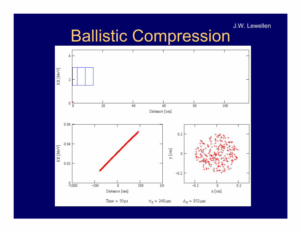
Ballistic CompressionJ.W. Lewellen

The BBC GunJ.W. Lewellen

Stupid Gun Tricks – Energy Compression
J.W. Lewellen

C:\lewellen\work\gun\design\highe
0
1
2
3
4
5
6
0 2 4 6 8 1
TM0,1,1
TM0,1,1 Photoinjector DesignTM0,1,1
Z (cm)
Ez (
MV/m
)
-2
-1.5
-1
-.5
0
.5
1
0 2 4 6 8 10 12 14
J.W. Lewellen

Higher-Order-Mode GunHigh-Power Prototype Design
J.W. Lewellen

Status and Future Plans
BBC gun
Modular BeamlineAssembly
Spectrometer /Filter Line
ExperimentalArea #1
laser port
J.W. Lewellen

The APS SASE FEL SchematicThe Low-Energy Undulator Test Line System
Present Configuration
APS SASE Project Goals• Characterize the SASE FEL output
and perform experiments with it.
• Assess the challenges associated with producing a SASE FEL in preparation for an x-ray regime machine.
S. Milton

Electrons are bunched under the influence of the light that they radiate.The bunch dimensions are characteristic of the wavelength of the light.
Excerpted from the TESLA Technical Design Report, released March 2001
Self-Amplified Spontaneous Emission
S. Milton

Basic Parameters for the APS FEL
PARAMETERS
Wavelength [nm]Regime 1
530Regime 2
120Regime 3
51Electron Energy [MeV] 217 457 700
Normalized rms Emittance(π mm-mrad) 5 3 3
Energy Spread [%] 0.1 0.1 0.1
Peak Current [A] 100 300 500
Undulator Period [mm] 33
Magnetic Field [T] 1.0
Undulator Gap [mm] 9.3
Cell Length [m] 2.73
Gain Length [m] 0.81 0.72 1.2
Undulator Length [m] 5 x 2.4 then 9 x 2.4 9 x 2.4 10 x 2.4
S. Milton

Undulator Line Details
~ 38 cmIntermodulegap
3.1K1 TField
9.4 mmGap3.3 cmPeriod
9 x 2.4 mLength
S. Milton

Optical Intensity Gain
0 5 10 15 20 250.01
0.1
1
10
100
1 .103
1 .104
1 .105
1 .106
1 .107
Distance [m]
Inte
nsity
[arb
. uni
ts]
0.57 mLg, meas.
0.59 mLg, theor.
≤ 0.1%energy spread
8.5 µmemittance
200 pCcharge
0.3 psbunch length
266 AIpeak
530nm10 March 01dataset DS1S. Milton

Recent Results at 130 nm
S. Milton

M. Pellin MSD/ANL
LEUTL
The First APS FEL Experiment

Single-Photon Ionization / Resonant Ionization to Threshold (SPIRIT)
M. Pellin MSD/ANLSPIRIT will use the high VUV pulse energy from
LEUTL to uniquely study –• Trace quantities of light elements:
- H, C, N, O in semiconductors with 100 times lower detection limit
• Organic molecules with minimalfragmentation- cell mapping by mass becomes feasible- polymer surfaces- modified (carcinogenic) DNA- photoionization thresholds
• Excited states of molecules- cold wall desorption in accelerators- sputtering of clusters
Coming 2002
The First APS FEL Experiment

).()(),( ττ −∝ tEtEtEsig
.)exp(),(),(2
∫∞
∞−
−∝ dttitEI sigFROG ωττω
For the second harmonic FROG
And the measured signal on the spectrometer is
FROG = Frequency Resolved Optical Gating
530 nm FEL
Beam splitter
BBO crystal
CorrelatedSignal to spectrometer
Cylindricallens
Spherical lensto image crystalonto spectrometer slit
Time-resolved measurement on the SASE FEL
Y. Li

0.0
0.3
0.5
0.8
1.0
-600 -400 -200 0 200 400 6005.0π
5.5π
6.0π
6.5π
7.0π
526 528 530 532 534 5360.0π
0.5π
1.0π
1.5π
2.0π
2.5π
3.0π
-600 -400 -200 0 200 400 600
268
267
266
265
264
263 Raw
τ (fs)
λ (n
m)
-600 -400 -200 0 200 400 600
268
267
266
265
264
263 Reconstructed
τ (fs)
Time In
tens
ity (a
. u. )
t (fs)
FROG sample 2
Intensity Phase
Phas
e (ra
d)
λ (nm)
0.0
0.3
0.5
0.8
1.0
-600 -400 -200 0 200 400 6000.0π
0.5π
1.0π
1.5π
526 528 530 532 534 5360.0π
1.0π
2.0π
3.0π
4.0π
-600 -400 -200 0 200 400 600
268
267
266
265
264
263 Raw
τ (fs)
λ (n
m)
-600 -400 -200 0 200 400 600
268
267
266
265
264
263 Reconstructed
τ (fs)
Time
Inte
nsity
(a. u
. )
t (fs)
FROG sample 1
Intensity Phase
Phas
e (ra
d)
λ (nm)
FROG examples
Y. Li

.)3
1(4
)/())]((1[exp)(),( 2
2
00∑=
−
−−−−−+=
eN
ij t
gjj
zo
ivzttttttcizEztE
σσσ
ω δ
,2 222
2
m
m
dtd
Φ′′+ΩΦ ′′+ΩΘ
==′′φ
φ
25 50 75 100
10-3
10-2
10-1
100
Exp data σ
δ/σz=23 m-1
σδ/σz=28 m-1
σδ/σz=33 m-1
| φ´´|
(mra
d fs
-2)
σt (fs)
.4
,43
1
2
02
Φ ′′+=Ω
+=Θ
t
zt c
σ
σσ
ωσ δ
The FEL output is
The total chirp in the pulse is
where
σt: coherence lengthΦm’’: group velocity dispersion in opticsσδ/σz: electron beam energy chirp
Observation of the intrinsic chirp and the imprint of theElectron beam energy chirp[PRL 89, 234801 (2002)]
Y. Li

Other topics (partial)• Midwest Accelerator Physics collaboration• Linear coupling of RMS emittance (L.Teng)• Electron cloud: beam-induced multipacting
resonance (K. Harkay with undergrad student L. Loiacono)
• CSR microbunching at SURF (K. Harkay with NIST, N. Sereno, and K-J. Kim)
• Beam halos (S. Milton with grad student D. Huang)

Summary
• AP Group pursuing accelerator physics R&D in a number of areas
• Highest-priority topics address near-term anticipated User requirements
• Also pursuing general accelerator physics topics and far-term light source development