ata 878.1 - 1999 local area network: token bus · ata 878.1-1999 sheet 7 of 75 1.2.2 optional...
TRANSCRIPT

ATA 878.1 - 1999 Local Area Network: Token Bus
Copyright © 1992, 1999 ARCNET Trade Association
www.arcnet.com [email protected]
All rights reserved by the ARCNET Trade Association.
Permission granted to make copies for review purposes.
ATA 878.1-1999 Sheet 1 of 75

ATA 878.1-1999 Sheet 2 of 75
Table of Contents
1. Introduction........................................................................................................................................6 1.1 Scope ..........................................................................................................................................6 1.2 Compliance Levels .....................................................................................................................6
1.2.1 Basic Facilities ...............................................................................................................6 1.2.2 Optional Facilities..........................................................................................................7 1.2.3 Media Interface and Topology Alternatives ..................................................................7 1.2.4 Compliance Nomenclature.............................................................................................7
1.3 Terminology and Notation ........................................................................................................7 1.3.1 Acronyms.......................................................................................................................7 1.3.1 Acronyms continued ......................................................................................................8 1.3.2 Definitions .....................................................................................................................9 1.3.3 Glossary of Traditional ARCNET® Terminology ........................................................10 1.3.4 Numbers.........................................................................................................................10 1.3.5 Times .............................................................................................................................11 1.3.6 Finite State Machines.....................................................................................................11
1.4 Acknowledgment ......................................................................................................................12
2. General Description ...........................................................................................................................13 2.1 Overview of 878.1 Capabilities.................................................................................................13
2.1.1 Basic Capabilities ..........................................................................................................13 2.1.2 Optional Capabilities .....................................................................................................14
2.2 878.1 Fundamentals ..................................................................................................................14 2.3 MAC Sublayer ..........................................................................................................................15 2.4 PHY Layer ................................................................................................................................15
2.4.1 Station Attachment ........................................................................................................15 2.4.2 Topology Alternatives ...................................................................................................15
2.5 Media.........................................................................................................................................16
3. Formats And Facilities.......................................................................................................................17 3.1 Formats......................................................................................................................................17
3.1.1 Basic Frame Format.......................................................................................................17 3.1.2 Reconfiguration Burst Format .......................................................................................17 3.1.3 Idle Condition ................................................................................................................17 3.1.4 Basic Symbol Units .......................................................................................................18 3.1.5 Basic Frame Types.........................................................................................................18
3.2 Basic Field Descriptions............................................................................................................19 3.2.1 Frame Identifier (FID) ...................................................................................................20 3.2.2 Destination Identifier (DID) ..........................................................................................20 3.2.3 Source Identifier (SID) ..................................................................................................20 3.2.4 Information Field Length (IL) .......................................................................................20 3.2.5 System Code (SC)..........................................................................................................21 3.2.6 Information Field (INFO) ..............................................................................................21 3.2.7 Frame Check Sequence (FCS) .......................................................................................21
3.3 Timers .......................................................................................................................................22 3.3.1 Timer, Lost Token (TLT) ..............................................................................................22 3.3.2 Timer, Identifier Precedence (TIP) ................................................................................23 3.3.3 Timer, Activity Timeout (TAC).....................................................................................23 3.3.4 Timer, Response Timeout (TRP)...................................................................................23 3.3.5 Timer, Recovery Time (TRC)........................................................................................24 3.3.6 Timer, Line Turnaround (TTA) .....................................................................................24 3.3.7 Timer, Medium Quiescent (TMQ).................................................................................24 3.3.8 Timer, Receiver Blanking (TRB) ..................................................................................24

ATA 878.1-1999 Sheet 3 of 75
3.3.9 Timer, Broadcast Delay (TBR)......................................................................................24 3.4 Flags ..........................................................................................................................................25
3.4.1 Receiver Inhibited (RI) ..................................................................................................25 3.4.2 Transmitter Available (TA) ...........................................................................................25 3.4.3 Transmitter Message Acknowledged (TMA) ................................................................25 3.4.4 Reconfiguration (RECON) ............................................................................................25 3.4.5 Broadcast Enabled (BE).................................................................................................26 3.4.6 PAC Detected (PF) ........................................................................................................26 3.4.7 ITT Detected (IF)...........................................................................................................26 3.4.8 FBE Detected (FF).........................................................................................................26
3.5 Registers....................................................................................................................................26 3.5.1 My Identifier (MYID)....................................................................................................26 3.5.2 Next Identifier (NID).....................................................................................................26 3.5.3 Transmit Destination (TXD)..........................................................................................26 3.5.4 Received Destination (RXD) .........................................................................................26
4. Protocol for 878.1 ..............................................................................................................................27 4.1 Overview...................................................................................................................................27
4.1.1 Frame Transmission.......................................................................................................27 4.1.2 Reconfiguration Burst Transmission .............................................................................27 4.1.3 Frame Reception ............................................................................................................27
4.2 Specification − Basic 878.1.......................................................................................................28 4.2.1 Receive Actions .............................................................................................................28 4.2.2 Finite-State Machine......................................................................................................28
5. Service Specifications........................................................................................................................37 5.1 MAC to LLC Service ................................................................................................................37
5.1.1 Interactions ....................................................................................................................37 5.1.2 Detailed Service Specifications .....................................................................................37 5.1.3 Service Event Diagrams.................................................................................................39
5.2 PHY to MAC Service................................................................................................................40 5.2.1 Interactions ....................................................................................................................41 5.2.2 Detailed Service Specifications .....................................................................................41
5.3 MAC to NMT Service...............................................................................................................43 5.3.1 Interactions ....................................................................................................................43 5.3.2 Detailed Service Specifications .....................................................................................43
5.4 PHY to NMT Service................................................................................................................44
6. Physical Layer....................................................................................................................................45 6.1 Symbol Encoding ......................................................................................................................45 6.2 Data Signaling Rate...................................................................................................................45 6.3 Symbol Timing..........................................................................................................................45 6.4 Symbol Decoding......................................................................................................................45
7. Station Attachment Specifications – Electrical Cable .......................................................................46 7.1 Scope.........................................................................................................................................46 7.2 Overview...................................................................................................................................46 7.3 Basic Signal Characteristics ......................................................................................................46
7.3.1 Transmitted Signals .......................................................................................................46 7.3.2 Received Signals............................................................................................................48 7.3.3 Coupling ........................................................................................................................49
7.4 System Considerations ..............................................................................................................49 7.4.1 Star Topology ................................................................................................................49 7.4.2 Bus Topology.................................................................................................................50 7.4.3 Medium Timing Jitter ....................................................................................................50
7.5 Medium Characterization ..........................................................................................................51 7.5.1 Coaxial Cable Electrical Characteristics........................................................................51

ATA 878.1-1999 Sheet 4 of 75
7.5.2 Twisted-Pair Cable Electrical Characteristics................................................................51 7.6 Safety and Grounding Requirements ........................................................................................51 7.7 Medium Interface Connector (MIC) .........................................................................................51
7.7.1 Coaxial Cable.................................................................................................................52 7.7.2 Unshielded Twisted Pair Cable......................................................................................52
8. Station Attachment Specifications – Fiber Optic Cable ....................................................................53 8.1 Scope.........................................................................................................................................53 8.2 Overview...................................................................................................................................53 8.3 Basic Signal Characteristics ......................................................................................................53
8.3.1 Transmitted Signals .......................................................................................................53 8.3.2 Received Signals............................................................................................................55
8.4 System Considerations ..............................................................................................................55 8.4.1 Star Topology ................................................................................................................55 8.4.2 Link Loss Budget...........................................................................................................55 8.4.3 Maximum Segment Length............................................................................................56 8.4.4 Medium Timing Jitter ....................................................................................................56 8.4.5 Overdrive .......................................................................................................................56
8.5 Medium Characterization ..........................................................................................................56 8.5.1 Attenuation ....................................................................................................................56 8.5.2 Segment Propagation Delay...........................................................................................57
8.6 Safety and Grounding Requirements ........................................................................................57 8.7 Medium Interface Connector (MIC) .........................................................................................57
8.7.1 SMA-Type Connector....................................................................................................57 8.7.2 ST-Type Connector .......................................................................................................57
9. Active Hub Specification...................................................................................................................58 9.1 Scope.........................................................................................................................................58 9.2 Overview...................................................................................................................................58 9.3 Active Hub Finite State Machine ..............................................................................................58 9.4 Hub Timing ...............................................................................................................................59
9.4.1 Unlatch Delay ................................................................................................................59 9.4.2 Bit Jitter .........................................................................................................................59 9.4.3 Throughput Delay..........................................................................................................60
10. System Code Assignments.................................................................................................................61
11. Alternate Physical Layer and Station Attachment Specification – Balanced Digital Multipoint System................................................................................................................................................62 11.1 Scope.........................................................................................................................................62 11.2 Overview...................................................................................................................................62 11.3 Basic Signal Characteristics ......................................................................................................62
11.3.1 Transmitted Signals .......................................................................................................63 11.3.2 Received Signals............................................................................................................64 11.3.3 Coupling ........................................................................................................................64 11.3.4 Receiver Sensitivity .......................................................................................................65
11.4 System Considerations ..............................................................................................................65 11.4.1 Twisted-Pair Cable ........................................................................................................65 11.4.2 Fail-safe Bias .................................................................................................................66 11.4.3 Termination....................................................................................................................67 11.4.4 Maximum Number of Stations.......................................................................................67 11.4.5 Maximum Segment Length............................................................................................67 11.4.6 Minimum Distance Between Stations............................................................................67
11.5 Safety and Grounding Requirements ........................................................................................68 11.5.1 Signal Common .............................................................................................................68 11.5.2 Protection Circuitry........................................................................................................68
11.6 Medium Interface Connector (MIC) .........................................................................................68

ATA 878.1-1999 Sheet 5 of 75
11.6.1 Telephone Style .............................................................................................................69 11.6.2 Subminiature D Connector ............................................................................................69
Annex .........................................................................................................................................................71
Appendix A ................................................................................................................................................73 A.1 Receiver Filter ...........................................................................................................................73 A.2 LLC Issues ................................................................................................................................73
A.2.1 Duplicate PAC Reception..............................................................................................73 A.2.2 LLC Retry on TA without TMA....................................................................................73 A.2.3 Automatic MAC Retry on NAK to an FBE...................................................................74
A.3 Compliance Using Convolution ................................................................................................74 A.4 Alternate Data Rate Timer Implementation ..............................................................................74

ATA 878.1-1999 Sheet 6 of 75
1. Introduction
1.1 Scope
For the purpose of compatible interconnection of information processing equipment via a token bus local area network operating at a basic data rate of 2.5Mbps, this standard:
(1) Defines the frame formats, (see Section 3); (2) Defines the medium access control protocol in terms of finite-state machines (see Section 4); (3) Defines service primitives and parameters for use at the conceptual interfaces between the medium
access control sublayer and the logical link control sublayer, and between the medium access control sublayer and the physical layer (see Section 5);
(4) Defines the physical layer functions (see Section 6); (5) Defines the medium interface connector for attachment of the physical medium to each station and
the electrical characteristics of the signaling method for copper media (see Section 7); (6) Defines the medium interface connector for attachment of the physical medium to each station and
the characteristics of the signaling method for fiber optic media (see Section 8); (7) Defines the operation of an active hub (see section 9);
and (8) Defines the medium interface connectors for attachment of the physical medium to each station and
the characteristics of the signaling method for a balanced digital multipoint system. The primary emphasis of this standard is to specify the homogeneous, externally visible characteristics needed for interconnection compatibility, while avoiding unnecessary constraints upon and changes to internal design and implementation of the heterogeneous processing equipment to be interconnected. A particular constraint in the development of this standard is to specify the operation of the network in such a manner that future implementations conforming to this standard shall be fully interoperable with the existing population of compliant stations, which numbered over 2 million at the time work on this standard was begun. Since the introduction of the standard in 1992, advances in integrated circuit technology have allowed the basic 878.1 technology to operate at data rates either above or below the 2.5Mbps data rate stated in the original 878.1 standard. Since these implementations were accomplished through the use of prescalers or higher clocking rates without modifying the basic 878.1 protocol, these implementations should be considered compliant to the standard as long as their characteristics and limitations are noted. For sake of clarity and simplicity, only the 2.5Mbps default implementation is characterized in this standard. Appendix A has been expanded to provide guidance on implementing alternate data rate 878.1 designs. 1.2 Compliance Levels
There are several sets of facilities described in this standard. (1) A set of basic facilities which all stations must implement; (2) A series of optional facilities which may be implemented on a facility-by-facility basis, and must
conform to this standard if implemented; and (3) Several media interface and topology alternatives.
1.2.1 Basic Facilities
The set of basic facilities provides for communication among all stations. Implementation of the complete set of basic facilities is mandatory for all stations. All portions of this standard are part of the basic facility set unless specifically designated as “optional”.

ATA 878.1-1999 Sheet 7 of 75
1.2.2 Optional Facilities
The only optional facility is three levels of extended timeouts, which permit operation over longer interconnection paths. 1.2.3 Media Interface and Topology Alternatives
The media interface alternatives include: (1) coaxial cable media, connected via a BNC connector; (2) twisted pair media, connected via an RJ11 or RJ45 connector; and (3) fiber optic media.
The media topology alternatives include: (1) star topology, in which each media segment is a point-to-point connection between a station
and a wiring concentrator (hub); and (2) bus topology, in which media segments may be multi-drop connections with a plurality of
stations attached along the path. 1.2.4 Compliance Nomenclature
The portions of this standard with which each related product complies shall be identified in the following manner:
(1) “878.1” indicates compliance with this standard for the basic facility set; (2) “-X” following 878.1 indicates support for all three levels of extended timeouts (if any
extended timeouts are supported, all must be supported); (3) “/C” following 878.1 indicates the use of a media interface connector for coaxial cable; (4) “/T” following 878.1 indicates the use of a media interface connector for twisted pair cable; (5) “/M” following 878.1 indicates the use of a media interface connector for "SMA" terminated
fiber optic cable; (6) “/F” following 878.1 indicates the use of a media interface connector for "ST" terminated fiber
optic cable; (7) “/S” following 878.1 indicates support for star topology; and (8) “/B” following 878.1 indicates support for bus topology. (9) “/E” following 878.1 indicates support for EIA-485 alternate physical layer.
Examples: “878.1-X/CS” indicates support for basic 878.1 with extended timeouts, for use on
star-wired, coaxial media. “878.1/TB” indicates support for basic 878.1, for use on bus-wired, twisted pair
media. “878.1-X/CTBS” indicates support for basic 878.1 with extended timeouts, for use on
either star or bus wiring with either coaxial or twisted pair media.
1.3 Terminology and Notation
This section defines some of the abbreviations, definitions of internal terminology, and numeric and state machine notation used in this document.
1.3.1 Acronyms
AB Alert Burst ACK Acknowledgment BE Broadcast Enabled flag CP Continuation Pointer CRC Cyclic Redundancy Check

ATA 878.1-1999 Sheet 8 of 75
1.3.1 Acronyms continued
DID Destination (station) IDentifier FBE Free Buffer Enquiry FCS Frame Check Sequence FF Fbe detected Flag FID Frame (type) IDentifier FR_BAD FRame BAD, invalid FSM Finite State Machine ID IDentifier IF Itt detected Flag IL Information (field) Length INFO INFOrmation (field) ISU Information Symbol Unit ITT Invitation To Transmit LLC Logical Link Control MAC Medium Access Control MIC Medium Interface Connector MYID MY (station) IDentifier NAK Negative AcKnowledgement NID Next (station) IDentifier NMT Network ManagementT PAC data PACket PDU Protocol Data Unit PF Pac detected Flag PHY PHYsical POR Power On Reset RECON network RECONfiguration RI Receiver Inhibited RSU Reconfiguration Symbol Unit RXD Receiver Destination identifier SC System Code SD Starting Delimiter SID Source (station) IDentifier SDU Service Data Unit TA Transmitter Available TAC Timer, ACtivity time-out TBR Timer, BRoadcast delay THU Timer, Hub Unlatch delay TIP Timer, Identifier Precedence TLT Timer, Lost Token TMA Transmitter Message Acknowledged TMQ Timer, Medium Quiescent TRB Timer, Receiver Blanking TRC Timer, ReCovery TRP Timer, ResPonse time-out TTA Timer, Turn Around TXD Transmitter Destination identifier

ATA 878.1-1999 Sheet 9 of 75
1.3.2 Definitions
activity (or network activity) A condition where the receiver at a station detects symbols representing binary ones with a predefined minimum periodicity.
address A value used to identify a station. Addresses must be unique within any set of stations connected to a single network.
broadcast transmission A transmission addressed such that it is received by all stations.
data packet A frame which conveys arbitrary information supplied by an LLC (or higher level) entity between stations.
frame A transmission unit that carries a physical PDU on the medium.
framing bits The three non-information symbols which precede the information bits in an ISU.
frame check sequence (FCS) The portion of a frame which contains error-detection code values for checking the information in that frame.
logical link control (LLC) That part of the data link layer that supports media independent data link functions and uses the services of the medium access control sublayer to provide services to the network layer.
medium The material on which the data may be transferred between stations. Twisted pair cable, coaxial cable, and optical fibers are each examples of media.
medium access control (MAC) The portion of the station that controls and mediates access to the medium.
MAC frame A frame which is used to communicate between MAC entities for the purpose of controlling access to and/or communication over the medium.
medium interface connector (MIC) The connector between the station and the medium through which all transmitted and received signals are specified.
network management (NMT) The conceptual control element of a station which interfaces with all of the layers of the station and is responsible for the setting and re-setting of control parameters, obtaining reports of error conditions, and determining if the station should be connected or disconnected from the medium.
physical (PHY) layer The layer responsible for interfacing with the medium, detecting and generating signals on the medium, and converting and processing signals received from the medium and medium access control sublayer.
protocol data unit (PDU) Information delivered as unit between peer entities which contains control information and, optionally, data.
repeater A device used to extend the length, topology, or interconnectivity of the medium beyond that imposed by the limitations on a single segment of medium between stations and/or repeaters. Repeaters are often referred to as hubs.
service data unit (SDU) Information delivered as a unit between adjacent entities which may also contain a PDU of the upper layer.

ATA 878.1-1999 Sheet 10 of 75
1.3.2 Definitions continued silence (on network)
A condition where the receiver at a station detects no symbols representing binary ones during a specified period of time.
starting delimiter (SD) The fixed pattern of symbols which is transmitted at the beginning of each frame and may be used to uniquely identify the beginning of that frame.
station A physical device that may be attached to a shared medium local area network for the purpose of transmitting and receiving information on that shared medium. A station is identified by its network address.
symbol A single signal element on the medium, which typically represents one bit, but may represent more than one bit under certain modulation and/or encoding schemes.
symbol unit A fixed-size group of symbols used for a particular purpose within a PDU.
time-out The expiration of the predetermined interval measured by a timer.
token The symbol of authority that is passed between stations using a token access method to indicate which station is currently in control of the medium.
token loop The deterministic, orderly sequence of stations, often called the “logical ring”, to which the token is passed during normal, steady-state network operation.
transmit The action of a station placing a frame or reconfiguration burst on the medium.
1.3.3 Glossary of Traditional ARCNET® Terminology
Prior to generation of this standard, typical ARCNET documentation used several terms which have been changed for standardization in order to bring them into closer agreement with conventional LAN standards terminology. The traditional ARCNET terms, along with the new terms, include:
ID ==> station address Node ==> Station Idle Timer ==> Activity Timer (TAC) RECON Timer ==> Lost-Token Timer (TLT) Alert Burst (AB) ==> Starting Delimiter (SD) Continuation Pointer (CP) ==> Information Length (IL) Cyclic Redundancy Check (CRC) ==> Frame Check Sequence (FCS)
ARCNET® is a registered trademark of Datapoint Corp. 1.3.4 Numbers
In this document, numerical constants are to be interpreted as decimal values unless preceded by a “0x” in which case they are in hexadecimal, or a "0b" in which case they are in binary. All cardinal numeric values in this document are to be treated as unsigned integers unless otherwise specified. All ordinal numeric values in this document are to be treated as 0-origin unless otherwise specified. In all bit position numbering, bit zero represents the least-significant bit.

1.3.5 Times
In this document, time intervals are designated “ms” for milliseconds (10-3 second), “μs” for microseconds (10-6 second), or “ns” for nanoseconds (10-9 second). If tolerances to specified time values are not listed, they may be assumed to be plus or minus 50% of one unit of the least significant digit shown. 1.3.6 Finite State Machines
The notation used in FSM diagrams is as follows:
STATE 1 STATE 2
14 INPUT or CONDITIONOUTPUT or ACTION
Figure 1.1
States are shown as vertical lines. Transitions are shown as horizontal lines with a number indicating the transition (for example, 14) and the arrow indicating the direction of transition. The leading digit(s) of the transition number is the number of the state being exited. The input or condition shown above the line is the requirement to make the transition. The output or action shown below the line occurs simultaneously with making the transition. The transition begins when the input occurs or the condition specified is met and is complete when the output or action has been completed. If the state transition is in progress, then no other FSM transition may be initiated. If the exit conditions of a state are satisfied at the time the state is entered, no action is taken in that state and the state is immediately exited. In the FSM diagrams the following notation is used:
Load(...) Load the specified field from the transmitter buffer Reset(...) Reset the specified timer(s) RX(...) Detect reception of the indicated frame or symbol RX(until ...) Receive and ignore anything until the specified symbol is detected TO(...) Time Out of the indicated timer TX(...) Transmit the indicated frame Set(...) Set the specified flag(s) Stop(...) Stop the specified timer(s) Store(...) Store the specified fields from the frame being received into the receiver buffer v Logical inclusive-OR & Logical AND ~ Logical NOT , Actions separated by commas are performed concurrently = Compare for equal != Compare for not equal := Assign value on right to register on left + Arithmetic unsigned addition mod Arithmetic unsigned modulus
ATA 878.1-1999 Sheet 11 of 75

ATA 878.1-1999 Sheet 12 of 75
1.4 Acknowledgment
Many structural, editorial, and appearance aspects of this document, as well as certain terminology and notation (particularly the FSM notation) are patterned after ANSI/IEEE Standard 802.5-1985. The authors of this document wish to thank the 802.5 Working Group for having written what is among the most readable network standards ever generated.

2. General Description This standard specifies the formats and protocols used by the 878.1 token passing bus medium access control (MAC) sublayer and physical (PHY) layer. The model and its relationship to the Open Systems Interconnection (OSI) reference model of the International Organization for Standardization (ISO) is illustrated in Figure 2.1.
OSI
Layers > 2
Layer 2
Layer 1
ARCNET
PHYPhysical
MACMedium Access Control
Logical Link ControlLLC
NMTNetwork
Management
MIC
Medium
Figure 2.1
Relation of OSI Reference Model to 878.1 Model
2.1 Overview of 878.1 Capabilities
878.1 provides • reliable transfer of variable-size data packets among a plurality of stations, • baseband signaling scheme, • a wide range of acceptable media.
Medium access control is accomplished through token passing, creating a logical ring on the physical bus. The bus structure permits use of a single interconnection conductor to each station. The media may be arranged using either a multi-centric star (also called an unrooted tree) structure or a multidrop bus structure for the physical interconnect topology. 878.1 provides as a basic capability of the protocol the ability to positively determine (for non-broadcasts) that the packet was copied by the destination MAC. This acknowledgment is presented in the form of the TMA flag as discussed in section 3.4.3. This capability is a part of the MAC but its use by the LLC is optional.(This capability is comparable in operation to the frame copied bit in ANSI/IEEE 802.5.)
2.1.1 Basic Capabilities
Basic 878.1 provides communication (1) among up to 255 stations, (2) at a rate of 2.5Mbps, (3) over media with aggregate path delays of up to 31μsec (using standard timeouts), (4) with data packets containing up to 507 data bytes.
ATA 878.1-1999 Sheet 13 of 75

2.1.2 Optional Capabilities
The only optional capability is • three levels of extended timeouts, which permit network operation over substantially greater lengths
of media.
2.2 878.1 Fundamentals
On 878.1, a token is used to designate the station which currently has control of the physical medium. The token is a control frame comprised of a unique signaling sequence which is transferred over the medium following each information transfer sequence. The station which holds the token has the exclusive right to transmit onto the medium. This right to transmit may be temporarily donated to another station, for use in acknowledging a transmission by the token holder. Within a specified time interval the token holder must relinquish control of the medium by passing the token to a predetermined other station. The token is passed from station to station in a circular fashion, as if on a logical ring. This token passing pattern is referred to as the token loop. All active stations participate in the token loop. Maintenance of the token loop is implemented by functions within the stations providing for token loop initialization, lost token recovery, addition of new stations to the token loop, and reconfiguration when stations are removed from the token loop. Token loop maintenance functions are replicated among all the stations on the network. 878.1 uses exclusively broadcast media. On a broadcast medium, all stations receive the signals transmitted by another station at approximately the same time. The creation of a logical ring for token passing on the physical bus is illustrated in Figure 2.2. In this diagram the token loop is denoted by a series of directional, dashed lines. Stations B, C, E, F, and G are participating in the token loop and are therefore able to perform information transfers over the medium. Stations A and D are inactive (typically powered off) and neither participate in, nor interfere with, the token loop and information transfers. Note that the token medium access method always involves sequential token passing in a logical sense. That is, during normal, steady state operation, the right to access the medium passes from station to station in an orderly, predetermined, and consistent manner. Furthermore, note that the physical connectivity has no impact on the order of token passing within the token loop, and that stations can respond to a query from the token holder independent of their position on the token loop and independent of their position on the physical medium.
(A)*
(D)*
B C
E F G
Medium
Figure 2.2 Logical Ring on Physical Bus
* - Stations A & D are inactive
The Medium Access Control (MAC) sublayer provides sequential access to the shared bus medium by passing control of the medium from station to station in a logically circular fashion. The MAC sublayer determines when the station has the right to access the shared medium by recognizing and accepting the token from the predecessor station and determines when the token shall be passed to the successor station. Upon receipt of the token, a station may perform an inquiry phase and a data transfer phase, prior to relinquishing control of the medium by performing a token transfer phase. If a station receives the token when it has no information to transfer over the medium, that station immediately enters the token transfer phase.
ATA 878.1-1999 Sheet 14 of 75

ATA 878.1-1999 Sheet 15 of 75
The token loop is automatically configured upon network initialization, and reconfigured dynamically as stations enter and leave the network. The sequence of token passing is from the active station with the highest address to the active station with the lowest address, then sequentially to active stations with successively higher addresses. A network reconfiguration process is invoked whenever the token is lost, a previously active station leaves the network, or a new station becomes active on the network. This reconfiguration process involves each station determining the address of its successor station on the token loop by polling of sequentially ascending station addresses. Once the address of the successor station is determined, tokens are passed directly to that station without further polling until the next network reconfiguration. In cases where the token has been lost or a new station has become active on the network, any existing network activity is forced to halt and the reconfiguration process is initiated. A time-out procedure, based on station address, is used to select the active station with the highest address for the purpose of starting the token loop (re-)initialization. 2.3 MAC Sublayer
The general functions of the MAC sublayer include: (1) distributed initialization, (2) lost token detection, (3) station address recognition, (4) frame encapsulation, (5) FCS generation and checking, (6) token generation and recognition, (7) new station addition and deletion, and (8) station failure error recovery.
2.4 PHY Layer
The general functions of the PHY layer include: (1) generation of symbols on the medium which correspond to signals received from the MAC sublayer, and (2) detection of symbols on the medium and processing of these symbols for delivery to the MAC sublayer.
2.4.1 Station Attachment
Stations are attached to the network media through specified Media Interface Connectors. (1) For coaxial cable media, a BNC connector is used. (2) For twisted pair cable media, an RJ11C or RJ45 connector is used. (3) For fiber optic cable an ST or SMA connector is used.
2.4.2 Topology Alternatives
Two media interconnect topologies are permitted − star topology and bus topology. (1) In star topology, each media segment is a point-to-point connection between a station and a wiring
concentrator (commonly called a hub) or between a pair of wiring concentrators. The wiring concentrator repeats the incoming signal from any media segment onto all other attached media segments. The wiring concentrator may amplify or re-generate the physical signals, but does not buffer nor interpret these signals. Star topology is applicable to all permitted media types.
(2) In bus topology, each media segment may have a plurality of stations connected along the segment. An electrical terminator is required at each end of each segment, and may be supplied by a connection to a wiring concentrator to permit mixing of bus and star topology segments on a single network. Bus topology is only applicable to electrical cable media.

ATA 878.1-1999 Sheet 16 of 75
2.5 Media
Suitable media for 878.1 includes (but is not limited to) coaxial, twisted pair (unshielded and shielded), and optical fiber cables. The specifications in Sections 7, 8, and 11 define the performance bounds to which an operating network, including the media and any repeaters or hubs, shall conform.

ATA 878.1-1999 Sheet 17 of 75
3. Formats And Facilities 3.1 Formats
There are two formats used on basic 878.1: (1) basic frames and (2) reconfiguration bursts.
In the following discussion, the figures depict the formats of the fields in the sequence they are transmitted on the medium, with the least-significant bit (shown at the left of each figure) transmitted first.
3.1.1 Basic Frame Format
SD
FID
FIS
SD = Starting Delimiter (6 basic symbols) FID = Frame Identifier (1 ISU) FIS = Frame Information Sequence (0-515 ISUs)
Basic frames are the means by which all control and information transfer functions occur between stations. 3.1.2 Reconfiguration Burst Format
RSU
RSU
RSU
- - - - -
RSU = Recon. Symbol Unit (9 basic symbols) (total of 765 RSUs)
The Reconfiguration Burst (RB) is used to force network initialization by terminating all activity on the network. The RB is longer than any type of frame, and will therefore interfere with the next Invitation To Transmit (ITT) frame, thereby preventing any station from receiving the token and obtaining the right to transmit onto the medium. The constant of 765 for the number of RSUs in the reconfiguration burst is only proper in conjunction with default timeouts. The correct length of the Reconfiguration Burst is 3060 RSUs with level 1 extended timeouts, 6120 RSUs with level 2 extended timeouts, and 12240 RSUs with level 3 extended timeouts. However, generation of these longer Reconfiguration Bursts when operating with extended timeouts is optional, because 878.1 implementations prior to this standard do not change their Reconfiguration Burst length with changes in the extended time-out level. Using a 765-RSU Reconfiguration Burst with extended timeouts does not prevent proper network operation, but can result in non-deterministic network reconfiguration times. 3.1.3 Idle Condition
When no station is transmitting, the medium is in the binary zero state (silence). The idle condition may be any duration, within the constraints of the Lost Token time-out (TLT) and/or Response time-out (TRP) timers. All types of (valid) transmissions begin with a binary one. When any type of transmission is taking place, a binary one will occur not less than once out of every 11 basic symbols. Silence for 11 basic symbol times may be used to detect the lack of (current) transmission activity; however, longer time periods are required to detect the lack of any network activity, due to allowable response times within the MAC protocol.

ATA 878.1-1999 Sheet 18 of 75
3.1.4 Basic Symbol Units
Basic symbol units are the elements used to construct basic frames and reconfiguration bursts. All valid basic transmissions contain an integral number of basic symbol units.
3.1.4.1 Starting Delimiter (SD)
1 1 1 1 1 1
1 = binary one
Every basic frame is started with these six symbols. NOTE: The Starting Delimiter is referred to as the "Alert Burst" in traditional documentation. 3.1.4.2 Information Symbol Unit (ISU)
1 1 0 i0 i1 i2 i3 i4 i5 i6 i7
1 = binary one 0 = binary zero i0 - i7 = information bits
Each byte of information being transferred between stations is preceded by two binary ones and one binary zero. The least significant bit of the information byte is transmitted first. Note that this section defines the format for a transmitted ISU. The requirements for the proper reception of an ISU are defined in the state diagrams. 3.1.4.3 Reconfiguration Symbol Unit (RSU)
1 1 1 1 1 1 1 1 0
1 = binary one 0 = binary zero
Each element of a reconfiguration burst contains these nine symbols. No sequence of other (valid) symbol units is capable of producing the same bit pattern as two or more, sequential RSUs; however, it is possible for an adjacent pair of valid ISUs to produce a bit pattern equivalent to a single RSU.
3.1.5 Basic Frame Types
The following is a description of each type of basic frame used on 878.1. In order for any basic frame to be considered valid at a receiving station, the last field of the frame must be followed by at least 9 basic symbol times of idle line condition (silence). Detection of any activity by the receiving station during this 9-symbol-time interval causes the preceding frame to be ignored.
3.1.5.1 Invitation To Transmit (ITT)
SD
ITT
DID
SD = Starting Delimiter (6 basic symbols) ITT = ITT Frame (1 ISU, value = 0x04) DID = Destination Identifier (2 ISUs)
The ITT frame is the means by which the right to transmit (token) is passed from one station to another.

ATA 878.1-1999 Sheet 19 of 75
3.1.5.2 Free Buffer Enquiry (FBE)
SD
FBE
DID
SD = Starting Delimiter (6 basic symbols) FBE = FBE Frame (1 ISU, value = 0x85) DID = Destination Identifier (2 ISUs)
The FBE frame is used to determine if the receiver at the destination station is currently able to accept a data packet. 3.1.5.3 Data Packet (PAC)
FCS Coverage
�
SD
PAC
SID
DID
IL
SC
INFO
FCS SD = Starting Delimiter (6 basic symbols) PAC = PAC Frame Identifier (1 ISU, value = 0x01) SID = Source Identifier (1 ISU) DID = Destination Identifier (2 ISUs) IL = Information Length (1-2 ISUs) SC = System Code (1 ISU) INFO = Information (0-507 ISUs) FCS = Frame Check Sequence (2 ISUs)
The PAC frame is used to transfer messages to the destination station(s). PAC frames may or may not have an information (INFO) field. 3.1.5.4 Positive Acknowledgment (ACK)
SD
ACK
SD = Starting Delimiter (6 basic symbols) ACK = ACK Frame (1 ISU, value = 0x86)
ACK frames are used to acknowledge successful receipt of PAC frames and as affirmative responses to FBE frames. 3.1.5.5 Negative Acknowledgment (NAK)
SD
NAK
SD = Starting Delimiter (6 basic symbols) NAK = NAK Frame (1 ISU, value = 0x15)
NAK frames are used as negative responses to FBE frames.
3.2 Basic Field Descriptions
The following is a detailed description of the individual fields used in the various types of basic frames defined above.

ATA 878.1-1999 Sheet 20 of 75
3.2.1 Frame Identifier (FID)
1 1 0 f0 f1 f2 f3 f4 f5 f6 f7
1 = binary one 0 = binary zero f0 - f7 = frame identifier
The FID field is used to uniquely indicate the type, therefore the format, of the frame. Valid frame type values (transmitted lsb first) are:
0x01 = PAC 0x04 = ITT 0x15 = NAK 0x86 = ACK 0x85 = FBE
If a receiver detects any value not shown above in the FID field, the frame is ignored. 3.2.2 Destination Identifier (DID)
1 1 0 a0 a1 a2 a3 a4 a5 a6 a7
1 1 0 a0 a1 a2 a3 a4 a5 a6 a7
1 = binary one 0 = binary zero a0-a7 = destination station address
The DID field contains two copies of the destination station address. A station only accepts an incoming frame if both copies of the destination station address are identical and are either equal to the station’s assigned address or are 0x00. The address value of 0x00 is used to identify broadcast frames which are to be received by all stations. 3.2.3 Source Identifier (SID)
1 1 0 a0 a1 a2 a3 a4 a5 a6 a7
1 = binary one 0 = binary zero a0 - a7 = source station address
The SID field contains the assigned address of the station transmitting the frame. 3.2.4 Information Field Length (IL)
Each PAC frame contains an IL field to indicate the number of ISUs in the INFO field of the frame. The IL field may be one or two ISUs in length, depending on the length of the INFO field. NOTE: The IL field is referred to as the "Continuation Pointer" (CP) in traditional documentation.
3.2.4.1 IL Field for INFO Fields containing 0 to 252 ISUs
1 1 0 n0 n1 n2 n3 n4 n5 n6 n7
1 = binary one 0 = binary zero n0 - n7 = (255 - N), N = INFO field length

ATA 878.1-1999 Sheet 21 of 75
3.2.4.2 IL for INFO Fields containing 256 to 507 ISUs
1 1 0 0 0 0 0 0 0 0 0
1 1 0 m0 m1 m2 m3 m4 m5 m6 m7
1 = binary one (mark) 0 = binary zero (space) m0-m7 = (511-N) N = INFO field length
NOTE: It is not permissible to send INFO fields with 253, 254, or 255 ISUs. Messages of these lengths must be extended to contain at least 256 ISUs to be transmitted validly.
3.2.5 System Code (SC)
1 1 0 s0 s1 s2 s3 s4 s5 s6 s7
1 = binary one 0 = binary zero s0 - s7 = system code value
The SC identifies the higher level protocol usage of the INFO field. NOTE: The system code is described as merely a conventional practice in traditional documentation. Usage of a system code in each PAC frame is mandatory for compliance with this standard. 3.2.6 Information Field (INFO)
1 1 0 d0 d1 d2 d3 d4 d5 d6 d7
1 = binary one 0 = binary zero d0 - d7 = data byte, (0 to 507 ISUs)
The INFO contains zero or more bytes that are intended for MAC, NMT, LLC, or higher level usage. The maximum length of this field is 507 bytes. 3.2.7 Frame Check Sequence (FCS)
1 1 0 b0 b1 b2 b3 b4 b5 b6 b7
1 1 0 c0 c1 c2 c3 c4 c5 c6 c7
1 = binary one 0 = binary zero b0-b7 = first check byte (FCS bits 0-7) c0-c7 = second check byte (FCS bits 8-15)
NOTE: The FCS field is referred to as the “Cyclic Redundancy Check” (CRC) field in traditional documentation. The FCS uses a 16-bit cyclic code based on the following standard generator polynomial of degree 16:
G(X) = X16 + X15 + X2 + 1 This discussion is provided strictly to clarify the FCS mechanism, and is not an indication of any mandatory implementation technique.

The FCS is generated using only the information bits from each ISU in the FID, SID, DID, IL, SC, and INFO fields of the frame. The transmitter initializes the interim FCS value to zero prior to transmitting each frame, serially updates the interim FCS value based on each information bit of each ISU transmitted, and transmits the two check bytes based on the value of the FCS at the end of the IL field. The receiver initializes the interim FCS value to zero prior to receiving each frame, serially updates the interim FCS value based on each information bit of each ISU received (including the ISUs containing the FCS), and checks the interim FCS value for being equal to zero after the last ISU of the frame has been received. If the resulting FCS value at the receiver is non-zero then the packet has been received in error and must be ignored. The diagram below is a block diagram of the logic needed to implement the FCS generator/checker as a linear feedback shift register (LFSR). The “D” (data in) is the value of the information bit currently being transmitted or received. The LFSR is shifted one bit such that FCS bit 1 receives the value from FCS bit 0 on the active edge of the clock.
XOR
XOR
XORD 0 1 2 3 4 5 6 7 8 9 10 11 12 13 14 15
Figure 3.1
3.3 Timers
The timers defined below are used at each station to control various operational characteristics of the network. Several of these timer values are fixed, while several others are variable, and must be set to equal values at all stations on the network. The variable timer values are referred to in terms of “extended timeouts”. Support for extended timeouts is optional, but if supported all extended time-out values must be selectable. Timer values listed assume a data rate of 2.5Mbps. The term reset when applied to timers, is to be understood to mean that the timer is reset to its initial value and (re)started. When a timer's interval expires it is said to have "timed out", which asserts a time-out condition which remains true until the timer is reset. A timer may be stopped prior to time-out in order to prevent its time-out condition from occurring.
3.3.1 Timer, Lost Token (TLT)
Each station has a timer TLT to recover from error conditions related to non-receipt of the token. Timer TLT is reset each time the station receives the token, and is used to initiate network reconfiguration in cases where a time-out occurs before the next token reception. The operation of TLT is detailed in the operational finite-state machine. The default value of TLT is 840ms; the alternate value, for all levels of extended time-out, is 1680ms. The tolerance on both of these timer values is ±10ms.
TLT Timer Timeout Level Value Tolerance
0* 1 2 3
840ms 1680ms 1680ms 1680ms
±10ms ±10ms ±10ms ±10ms
* - default value NOTE: This timer is referred to as the “RECON time-out” in traditional documentation.
ATA 878.1-1999 Sheet 22 of 75
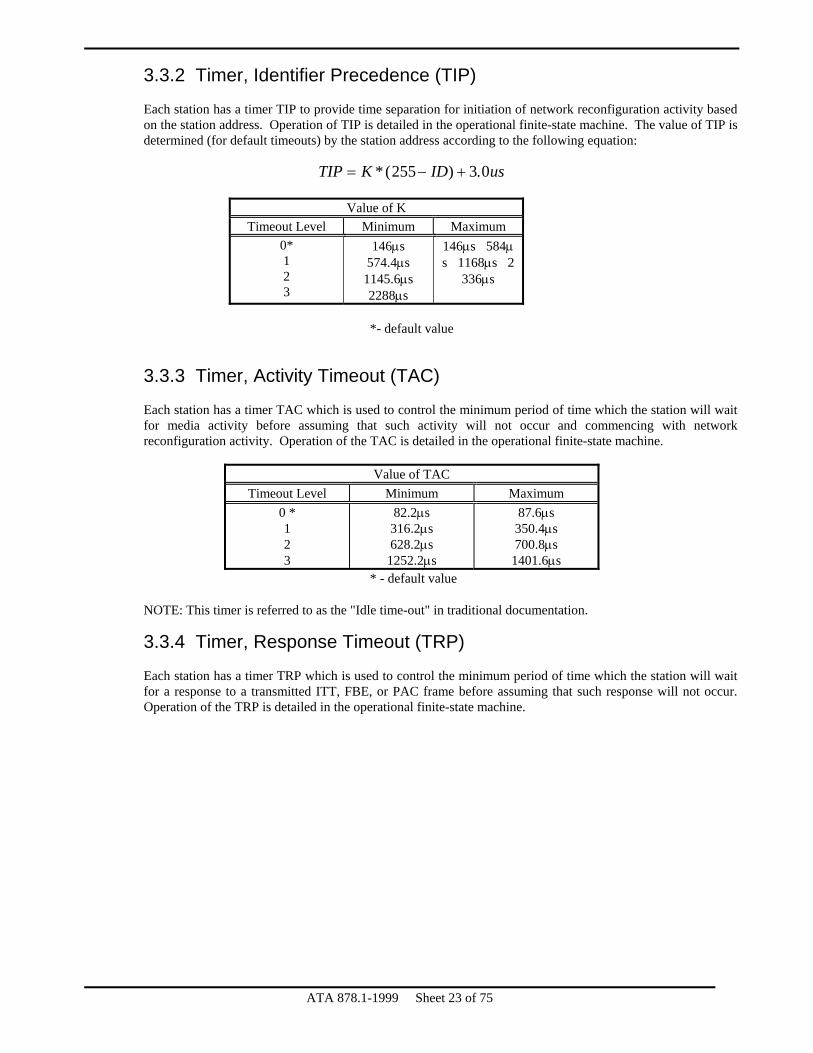
3.3.2 Timer, Identifier Precedence (TIP)
Each station has a timer TIP to provide time separation for initiation of network reconfiguration activity based on the station address. Operation of TIP is detailed in the operational finite-state machine. The value of TIP is determined (for default timeouts) by the station address according to the following equation:
TIP K ID us= − +*( ) .255 3 0
Value of K Timeout Level Minimum Maximum
0* 1 2 3
146μs 574.4μs
1145.6μs 2288μs
146μs�584μs�1168μs�2
336μs
*- default value
3.3.3 Timer, Activity Timeout (TAC)
Each station has a timer TAC which is used to control the minimum period of time which the station will wait for media activity before assuming that such activity will not occur and commencing with network reconfiguration activity. Operation of the TAC is detailed in the operational finite-state machine.
Value of TAC Timeout Level Minimum Maximum
0 * 1 2 3
82.2μs 316.2μs 628.2μs
1252.2μs
87.6μs 350.4μs 700.8μs
1401.6μs * - default value
NOTE: This timer is referred to as the "Idle time-out" in traditional documentation. 3.3.4 Timer, Response Timeout (TRP)
Each station has a timer TRP which is used to control the minimum period of time which the station will wait for a response to a transmitted ITT, FBE, or PAC frame before assuming that such response will not occur. Operation of the TRP is detailed in the operational finite-state machine.
ATA 878.1-1999 Sheet 23 of 75

ATA 878.1-1999 Sheet 24 of 75
Value of TRP
Timeout Level Minimum Maximum 0 * 1 2 3
74.6μs 283.4μs 561.8μs
1118.6μs
77.6μs 310.4μs 620.8μs
1241.6μs * - default value
3.3.5 Timer, Recovery Time (TRC)
Each station has a timer TRC to provide time separation between the end of a response time-out and the start of a token pass. Operation of the TRC is detailed in the operational finite-state machine.
Value of TRC Minimum Maximum
1.6μs 3.4μs 3.3.6 Timer, Line Turnaround (TTA)
Each station has a timer TTA to control the minimum interval between the end of a received transmission and the start of a transmitted response. Operation of the TTA is detailed in the operational finite-state machine.
Value of TTA Minimum Maximum
12.0μs 13.6μs 3.3.7 Timer, Medium Quiescent (TMQ)
Each station has a timer TMQ to control the sampling interval used to determine if a transmission is taking place on the medium. The lack of any detected one-bits during a TMQ period indicates a quiescent condition.
Value of TMQ Minimum Maximum
3.2μs 4.8μs 3.3.8 Timer, Receiver Blanking (TRB)
Each station has a timer TRB to control the interval after the end of a transmission from this station that the receiver is to be blanked before valid network activity can be received.
Value of TRB Minimum Maximum
5.6μs 6.4μs 3.3.9 Timer, Broadcast Delay (TBR)
Each station has a timer TBR to control the minimum interval between the end of a broadcast transmission and the start of a token pass. Operation of the TBR is detailed in the operational finite-state machine. This timer need not change as a function of timeout level, however, 878.1 implementations prior to this standard did in fact increase TBR with increasing timeout levels. Care should be exercised that TBR not exceed the value of TAC for proper operation.

ATA 878.1-1999 Sheet 25 of 75
Value of TBR
Minimum Maximum 15.6μs 200.0μs
3.4 Flags
Flags are used to remember the occurrence of a particular event. They are set when the event occurs and are cleared as specified in the finite state machine definitions.
3.4.1 Receiver Inhibited (RI)
This flag is set upon successful receipt of a data packet addressed to this station, or a broadcast data packet, for which the reception and transfer to the station data buffer has been successfully completed and the frame check sequence verified. This flag is cleared by LLC functions when an empty buffer is available within the station data buffer and reception of data packets is again allowed. While this flag is set, no data packets are accepted by the station; however, invitation to transmit frames and free buffer enquiry frames, are accepted by the station at all times. If an 878.1 implementation permits LLC functions to set this flag, logic must be included to ensure that it is not possible to change the state of RI during the reception of a data packet. 3.4.2 Transmitter Available (TA)
This flag is set upon completion of a data packet transmission attempt except in cases where a negative acknowledgment is received in response to a free buffer enquiry. This flag is cleared by LLC functions when a new data packet is available for transmission in the station's data buffer and packet transmission is to be performed on the next token reception. When this flag is set, this station passes the token immediately upon receipt, without attempting a transmission. If an 878.1 implementation permits LLC functions to set this flag, logic must be included to ensure that it is not possible to change the state of TA during the transmission of a data packet. 3.4.3 Transmitter Message Acknowledged (TMA)
This flag is set coincident with TA in cases where the destination station has provided a positive acknowledgment to successful receipt of a data packet. TMA serves as indication that the data packet has been successfully copied into the receive buffer at the destination station. This flag may be cleared by LLC functions and is automatically cleared when TA is cleared. The case where both TA and TMA are set is indication of guaranteed delivery into a receiver buffer at the destination. The setting of TA while TMA remains clear is an indication of probable failure of the data packet delivery. However, the destination station may have successfully received the data packet even when TA is set while TMA remains clear at the source station (for example, in cases where the ACK frame is destroyed by a RECON Burst.). 3.4.4 Reconfiguration (RECON)
This flag is set when the activity timer (TAC) expires, indicating that a network reconfiguration needs to occur. This flag is cleared by LLC or NMT functionality as appropriate.

ATA 878.1-1999 Sheet 26 of 75
3.4.5 Broadcast Enabled (BE)
This flag is set and cleared as desired by LLC or NMT functionality. When this flag is set, reception of broadcast data packets by this station is enabled. When this flag is cleared, broadcast data packets are ignored by this station. 3.4.6 PAC Detected (PF)
This is an internal flag which is set when the FID of an incoming frame is decoded as being a PAC. This flag is set and cleared by the operational finite-state machine. 3.4.7 ITT Detected (IF)
This is an internal flag which is set when the FID of an incoming frame is decoded as being an ITT. This flag is set and cleared by the operational finite-state machine. 3.4.8 FBE Detected (FF)
This is an internal flag which is set when the FID of an incoming frame is decoded as being an FBE. This flag is set and cleared by the operational finite-state machine.
3.5 Registers
Registers are used to remember a particular value. They are loaded as specified in the finite state machine definitions.
3.5.1 My Identifier (MYID)
This is an 8-bit register which contains the specified address of this station and is used to insert source identification field contents in outgoing data packets and as a reference for incoming address recognition. 3.5.2 Next Identifier (NID)
This is an 8-bit register which holds the station address of the successor station on the logical ring and is used to address the token on token passes from this station. 3.5.3 Transmit Destination (TXD)
This is an 8-bit register which holds the destination station address of the current outgoing data packet (if any). This is used to designate the intended recipient(s) of the outgoing packet. 3.5.4 Received Destination (RXD)
This is an 8-bit register which holds the destination station address received in the current incoming data packet (if any). This is used to distinguish received broadcast packets from explicitly-addressed packets.

ATA 878.1-1999 Sheet 27 of 75
4. Protocol for 878.1 This section specifies the procedures that are used in the Medium Access Control (MAC) sub-layer.
4.1 Overview
The subsections of 4.1 provide a descriptive overview of frame transmission and reception. The formal specification of the operation of basic 878.1 is given in 4.2.
4.1.1 Frame Transmission
Access to the physical medium is controlled by the passing of a token around a logical ring determined by the sequence of ascending station addresses, and without regard to the physical distribution of these stations about the physical medium. The station in receipt of the token has the opportunity to transmit a frame or group of frames, including not more than one data packet. Upon request for transmission of an LLC PDU or NMT PDU, MAC prefixes the PDU with the appropriate SD, FID, and address fields and enqueues the PDU to wait for the reception of a token that may be used for its transmission. If the DID of the PDU is zero (indicating a broadcast), upon receipt of a token, the station
(1) sends the data packet frame, and (2) after waiting the broadcast delay (TBR) the station generates an ITT frame to pass the token to the
next station on the logical ring. If the DID of the PDU is non-zero (indicating an explicitly addressed destination), upon receipt of the token, the station
(1) transmits an FBE frame, (2) waits for a responding ACK or NAK frame from the addressed destination, and (3) sends the data packet frame if an ACK was received in response to the FBE. (4) After sending the data packet frame, the station again waits for an ACK frame from the destination. (5) After receiving this final ACK (or exceeding the specified time-out without receiving the ACK), the
station generates an ITT frame to pass the token to the next station on the logical ring. 4.1.2 Reconfiguration Burst Transmission
When network reconfiguration is needed, as detected by power-on reset conditions or the TLT time-out at the station, the station activates its transmitter to transmit a reconfiguration burst. The reconfiguration burst does not communicate useful information, and is used to force network (re-) initialization by terminating all activity on the network. Network activity may be terminated in this manner because the reconfiguration burst is longer than any type of frame and will, therefore, interfere with the next ITT frame. By interfering with the ITT frame, the reconfiguration burst prevents any station from receiving the token. This will ultimately result in a TAC and/or TLT time-out at all stations. 4.1.3 Frame Reception
Stations, while receiving the incoming symbol stream, check for frames to be acted upon. If the FID indicates a MAC frame (any of ITT, ACK, PAC, FBE, or NAK), the frame control information is interpreted by all stations on the network. In addition, if the frame is a PAC and the frame's DID field matches the station's assigned address or broadcast address, the SID, DID, IL, SC, and INFO fields are copied to a receive buffer and subsequently forwarded to the appropriate sublayer.
4.2 Specification − Basic 878.1
Operation of the network is described in this section. In the case of a discrepancy between the FSM diagram/tables and the supporting text, the FSM diagram/tables shall take precedence.

ATA 878.1-1999 Sheet 28 of 75
The MAC receives from the PHY layer a serial stream of basic symbols. Each basic symbol shall be one of the following (see Section 6 for a detailed description of these symbols):
0 = binary zero 1 = binary one
From the received symbols, MAC detects various types of frames including MAC frames and LLC information frames. In turn, MAC stores values, sets flags, controls timers, and performs various internal actions, as well as generating tokens, frames, and reconfiguration bursts and delivering them to the PHY layer.
4.2.1 Receive Actions
The receiver discriminates between two varieties of frames: validly formed frames and bad frames (FR_BAD). A validly formed frame:
(1) begins with a valid SD as defined for state transition 21 of the 878.1 Protocol (paragraph 4.2.2.5), (2) has an FID value for ITT, ACK, PAC, FBE, or NAK immediately following the SD, (3) contains an integral number of ISUs from among 1, 3, 8 to 260, or 265 to 516 following the SD, (4) has at least two binary ones and exactly one binary zero preceding the information byte in each ISU, (5) has equal values in both ISUs of the DID field (for ITT, FBE, and PAC frames only), (6) has a valid FCS (for PAC frames only), and (7) has at least nine binary zeros following the last ISU.
A bad frame is any frame which does not meet all of these requirements. 4.2.2 Finite-State Machine
The operational finite-state machine is illustrated in Figures 4.1, 4.2, and 4.3, and explained as follows:
4.2.2.1 (x1) Power-On Reset
Whenever a station is powered on, or is allowed to become active on the network in cases where initialization of network activity is inhibited after power-on, an immediate entry is made to State 0. 4.2.2.2 (x2) Lost Token Timeout
Whenever TLT times out, an immediate transition to State 0 occurs, independent of what is occurring elsewhere in the operational FSM. 4.2.2.3 State 0: Reset
In Reset State any necessary physical initialization is performed before forcing network reconfiguration. (01) Exit from Reset State As soon as physical initialization is completed, a Reconfiguration Burst is transmitted to force network reconfiguration; token loop regeneration is prepared by setting NID to MYID; the TLT and TMQ timers are reset; and a transition is made to State 1. State 1 is entered here so that this station will wait if another Reconfiguration Burst is in progress.
4.2.2.4 State 1: WT_IDLE (Wait for Quiescent Medium)
While in this state the station waits until it detects silence (continuous binary zeros) on the medium for the TMQ interval.
(11) Loop on Activity

ATA 878.1-1999 Sheet 29 of 75
If a binary one is detected, the TMQ timer is reset and the station stays in State 1. (12) Exit on Silence If TMQ times out, this means that no valid network activity is occurring, since all symbol units include at least one binary one every TMQ interval. When TMQ times out, TAC is reset and a transition is made to State 2 to wait for new activity.
4.2.2.5 State 2: WT_ACT (Wait for Activity on Medium)
While in this state the station waits up to the TAC interval for activity (binary ones) on the medium. If activity is detected, the new frame is decoded. If TAC times out, network reconfiguration occurs.
(21) Activity Detected When a binary one is detected, this indicates the beginning of an SD (or a Reconfiguration Burst, which will end up being ignored due to FR_BAD). The remaining ones in the SD are bypassed; the PF, IF, and FF flags are reset to prepare for frame type decoding; and entry to State 3 is made as soon as the first binary zero (which will be the third symbol of the FID ISU) is detected. (22) No Activity Detected If TAC times out then no network activity is occurring, which means that network reconfiguration is required to regenerate the token loop. TIP is reset to cause the reconfiguration process to start at the active station with the highest ID; NID is set to this station's ID to set up for polling of possible successor stations on the token loop; and the RECON flag is set to indicate to NMT that a network reconfiguration has occurred.
4.2.2.6 State 3: DCD_TYPE (Decode Frame Type)
In this state the FID field of the frame being received is decoded to determine the frame type.
(31) Frame Not Acceptable The incoming frame cannot be accepted if the FID indicates a type other than PAC, FBE, or ITT; if the FID indicates a PAC but the receiver is inhibited (RI is set); or if the frame has invalid format (FR_BAD). In any of these cases TMQ is reset and a transition is made to State 1 to wait for the end of this frame. If State 3 was entered due to detection of binary ones from a Reconfiguration Burst, transition 31 occurs due to FR_BAD and the remainder of the Reconfiguration Burst is ignored by looping in State 1 through transition 11.
(32) FBE Detected The incoming frame is an FBE, so FF is set to remember this frame type and entry is made to State 4 to decode the DID. (33) ITT Detected The incoming frame is an ITT, so IF is set to remember this frame type and entry is made to State 4 to decode the DID. (34) PAC Detected (with RI clear) The incoming frame is a PAC and PAC reception is enabled (RI clear), so PF is set to remember this frame type, the SID field is stored into the receiver buffer, and entry is made to State 4 to decode the DID.
4.2.2.7 State 4: DCD_DID (Decode Destination Identifier)
In this state the first ISU of the DID field is inspected to distinguish between frames addressed to this station, broadcast frames (if reception of broadcasts is enabled), and frames addressed to other stations.
(41) DID Not Acceptable

ATA 878.1-1999 Sheet 30 of 75
The incoming frame is rejected based on its DID if that DID is zero on either a FBE or ITT; if that DID is zero on a PAC when broadcast reception is not enabled (BE clear); if that DID is neither zero nor this station's ID; or if the DID field has invalid format (FR_BAD). In any of these cases TMQ is reset and a transition is made to State 1 to wait for the end of this frame. NOTE: Unequal values in the two ISUs of the DID field of an incoming PAC frame are a case of FR_BAD, and can be rejected through transition 41; however, it is acceptable for the receiver to store such a PAC into the receiver buffer, by making transition 45 based on the value of the first ISU of the DID field (assuming other framing requirements are met), and to subsequently reject the PAC in transition 131 due to the FR_BAD condition from the unequal DID ISU values.
(42) FBE Addressed to Station The incoming FBE is addressed to this station and is valid, so TTA is reset to ensure proper line turnaround and entry is made to state 6 to respond to the FBE. (43) ITT Addressed to Station When No Transmission Pending The incoming ITT is addressed to this station and is valid, but this station has no PAC awaiting transmission (TA), so TTA is reset to ensure proper line turnaround and entry is made to state 7 to pass the token immediately. (44) ITT Addressed to Station When Transmission Pending The incoming ITT is addressed to this station and is valid when this station has a PAC awaiting transmission (~TA), so TTA is reset to ensure proper line turnaround and entry is made to state 9 to begin the PAC transmit sequence. (45) PAC Addressed to Station or Broadcast The incoming PAC is valid and is either addressed to this station or is a broadcast (while reception of broadcasts is enabled), so the incoming DID (second ISU only), IL, SC, and INFO fields are stored into the receiver buffer and transition is made to state 13 to complete reception of the PAC.
4.2.2.8 State 5: RECON (Network Reconfiguration)
In this state network reconfiguration begins by monitoring for network activity while waiting for the time-out of TIP. If this time-out occurs this station begins the reconfiguration process by commencing with token passing. If network activity is detected before this time-out occurs, then some other station has initiated token passing, so this station can suspend its reconfiguration attempt. (51) Activity Detected
Activity has been detected before the time-out of TIP, indicating that a station with a higher ID is active on the network and has begun the reconfiguration process. TIP is stopped, and entry is made to State 1 with TMQ reset to cause the remainder of the detected activity to be ignored. NOTE: Unlike activity detected when in State 2, the activity detected when in State 5 is not decoded as to type. This is why it is necessary that the first attempted token pass of the reconfiguration process must be to MYID, not to MYID+1.

ATA 878.1-1999 Sheet 31 of 75
(52) TIP Timeout TIP has timed out before any activity has been detected, indicating that this station has the highest active ID and must (re)establish the token loop. TLT and TRC are reset and entry is made to State 7 to begin token passing.
4.2.2.9 State 6: RX_FBE (Respond to FBE)
This state is entered when this station has received an FBE and must generate a response upon time-out of TTA.
(61) Respond to FBE with ACK The RI flag is clear, indicating that the receiver is enabled and a receive buffer is available, so an ACK is transmitted and entry is made to State 1 to wait for the medium to become silent. (62) Respond to FBE with NAK The RI flag is set, indicating that the receiver is disabled and/or no receive buffer is available, so a NAK is transmitted and entry is made to State 1 to wait for the medium to become silent.
4.2.2.10 State 7: PASS_TOKEN
The token is passed to NID.
(71) Send ITT Upon time-out of the TTA (turnaround), TRC (recovery), or TBR (broadcast delay) timer, an ITT is sent to NID; the TRP (response) and TRB (receiver blanking) timers are reset; the TTA, TRC, and TBR timers are stopped; and entry is made to State 8 to await a response to the token.
4.2.2.11 State 8: WT_TOKEN (Wait for Activity After Passing Token)
In this state the station monitors the medium after passing the token to determine if another active station has received the token and commenced network activity. If so, this activity is decoded; if not, this station’s NID is incremented and token passing is retried.
(81) No Response to Token The expiration of TRP without detection of network activity indicates that the token has not been received by an active station. To continue attempting to locate an active NID, the value of NID is incremented (modulo 256) and State 7 is entered to attempt a token pass to the new NID value. (82) Response to Token The detection of activity (a binary one) before the expiration of TRP indicates that the token has been accepted by another active station. The remaining ones in the SD are bypassed; the PF, IF, and FF flags are reset to prepare for frame type decoding; TRP is stopped; and entry to State 3 is made as soon as the first binary zero (which will be the third symbol of the FID ISU) is detected. This entry to State 3 is equivalent to transition 21.

ATA 878.1-1999 Sheet 32 of 75
4.2.2.12 State 9: TX_FBE (Transmit FBE)
This state is entered when a PAC is to be transmitted and the token has been received. If the PAC is a broadcast, no action is taken and immediate packet transmission (State 11) occurs. If the PAC is not a broadcast an FBE is transmitted to determine if the destination station has its receiver enabled and has a buffer available to accept the PAC.
(91) Send FBE If the DID of the pending PAC is non-zero, an FBE is sent and entry is made to State 10 to wait for response to this FBE. (92) Do Not Send FBE If the DID of the pending PAC is zero, indicating a broadcast, no action is taken and immediate entry is made to State 11 to transmit the PAC.
4.2.2.13 State 10: WT_FBE (Wait for Reply to FBE)
In this state the station waits for a response to an FBE. If the response is an ACK, the PAC is transmitted. If the response is a NAK, the token is passed and the transmission remains pending. If the response is invalid or does not occur, the transmission is aborted.
(101) No Response to FBE If TRP expires without any incoming activity the transmission is aborted (TA set) and entry is made to State 7 to pass the token. (102) NAK in Response to FBE If a NAK is received, the transmitter remains enabled (TA remains clear) and entry is made to State 7 to pass the token. Because TA remains clear, the transmission will be re-attempted when the next token is received by this station. (103) ACK in Response to FBE If an ACK is received entry is made to State 11 to transmit the PAC. (104) Response to FBE Which is Neither ACK nor NAK If activity is detected which is neither an ACK nor a NAK, whether validly framed or not, the transmission is aborted and State 1 is entered to ignore any remaining activity in the frame. This has the effect of forcing network reconfiguration because this station does not pass the token. The reasoning behind this is that any situation where an FBE response does occur, but is neither an ACK nor a NAK, the network probably needs reconfiguration. Because TA remains clear, the transmission will (eventually) be re-attempted.
4.2.2.14 State 11: TX_PAC (Transmit PAC)
The pending PAC transmission is sent. (111) Non-broadcast PAC If the DID of the PAC is non-zero, the PAC is sent and entry is made to State 12 to wait for a response to the PAC. (112) Broadcast PAC If the DID of the PAC is zero, indicating a broadcast, the PAC is sent, the transmitter is disabled (TA set), and entry is made to State 7 to pass the token.

ATA 878.1-1999 Sheet 33 of 75
4.2.2.15 State 12: WT_PAC (Wait for Reply to PAC)
In this state the station waits for a response to a PAC. If the response is an ACK, successful delivery is indicated and the token is passed. If the response is invalid or does not occur, the token is passed without indicating successful delivery.
(121) No ACK Received If TRP expires without any incoming activity, or if the detected activity is invalid or is not an ACK, the transmitter is disabled (TA set) and entry is made to State 7 to pass the token. (122) ACK Received If an ACK is received the message acknowledgment flag (TMA) is set, the transmitter is disabled (TA set), and entry is made to State 7 to pass the token.
4.2.2.16 State 13: RX_PAC (Complete Reception of PAC)
In this state the PAC has been received and the FCS must be checked and appropriate completion action taken.
(131) PAC Invalid The PAC is invalid due to a framing error, FCS error, or mismatch of DID bytes. No confirmation is sent and entry is made to State 1 to wait for the medium to become idle. (132) Broadcast PAC Received Successfully The PAC is valid and is a broadcast, for which no acknowledgment is to be sent. The receiver is inhibited (RI set) and entry is made to State 1 to wait for the medium to become idle. (133) Non-Broadcast PAC Received Successfully The PAC is valid and is addressed to this station. The receiver is inhibited (RI set), TTA is reset to generate an interframe gap, and entry is made to State 14 to generate an ACK.
4.2.2.17 State 14: PAC_ACK (Send Reply to PAC)
This state is entered after successful receipt of a non-broadcast PAC to send the confirming ACK.
(141) Send ACK An ACK is sent and entry is made to State 1 to wait for the medium to become idle.

4.2.2.18 State Transition Diagrams
A legend of FSM notation appears in section 1.3.
State 5:Recon
51RX("1")
State 1:WT_IDLE
11Reset(TMQ),Stop(TIP)
x1RX("1")
State 0Reset
POR
T0(TLT)
01TX(Recon_burst)
NID:=MYID,Reset(TLT,TMQ)
x2
Reset(TMQ)
T0(TMQ)12
State 2:WT_ACT
22 T0(TAC)Reset(TIP)NID:=MYIDSet(Recon)
52 T0(TIP)Reset(TLT,TRC)
state 7
state 3:DCD_TYPE
31
RX("1")RX(until "0"),Reset(PF,IF,FF)
21Reset(TAC)
(FID=PAC & RI)Reset(TMQ)
state 6(61,62)
state 14(141) RX(FR_BAD) v
(DID!=0 & DID!=MYID) v(DID=0 & ~PF) v
Reset(TMQ)(DID=0 & ~BE)
state 4:DCD_DID
41
FID=FBESet(FF)
32
33
34
state 6
FID=ITTSet(IF)
FID=PAC & ~RISet(PF),Store(SID)
DID=MYID & FF &42
state 13(131,132)
state 10(104)
state 13
state 7
(DID+MYID & PF) v (DID=0 & PF & BE)Store(DID,IL,Sc,INFO)
DID=MYID & IF ~RX(FR_BAD) & TAReset(TTA,TLT)
44DID=MYID & IF &
Reset(TTA,TLT)
43
45
Reset(TAT)
state 9
RX(FR_BAD) v (FID!=PAC & FID!=FBE & FID!=ITT) v
~RX(FR_BAD)
~RX(FR_BAD) & ~TA
TXD=Load(DID)
Figure 4.1 − Operational Finite-state Machine (Part 1 of 3)
ATA 878.1-1999 Sheet 34 of 75

state 8:WT_TOKEN
state 7:PASS_TOKEN
T0(TTA) v T0(TRC) v T0(TBR)71TX(ITT(NID)),Reset(TRP,TRB),Stop(TTA,TRC,TBR)
state 4(43)
state 5(52)
82 T0(TRB) & RX("1")RX(until "0"),Reset(FF,IF,PF),Stop(TRP)
state 3
state 4(44)
State 9:TX_FBE
81
state 10:WT_FBE
101
NID:=(NID+1 mod 256),Reset(TRC)
T0(TRP)
T0(TRP)Set(TA)
(T0(TRB) & RX(NAK)) &~RX(FR_BAD)Reset(TTA),Stop(TRP)
102
T0(TTA) & TXD!=0
TX(FBE(TXD)),Reset(TRP,TRB)
RX(FR_BAD) vRX(FID!=ACK & FID!=NAK)104Reset(TMQ),Stop(TRB)
state 1
91
92 TXD=0
state 11:TX_PAC
112
103(T0(TRB) & RX(ACK)) &~RX(FR_BAD)Reset(TTA),Stop(TRP)
T0(TTA) & TXD=0
TX(PAC),Reset(TBR),Set(TA)
RX(FID!=ACK) vT0(TRP) v RX(FR_BAD)Set(TA),Reset(TRC)
RX(ACK) & ~RX(FR_BAD)
state 12:WT_PAC
121
122
111T0(TTA) & TXD!=0TX(PAC),Reset(TRP)
Reset(TTA),Stop(TRP),
Set(TA,TMA)
Figure 4.2 − Operational Finite-state Machine (Part 2 of 3)
ATA 878.1-1999 Sheet 35 of 75
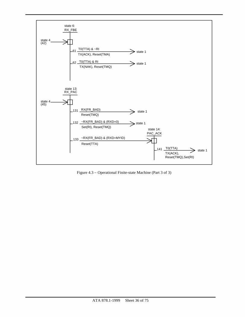
state 6:RX_FBE
state 4(42)
61
62
T0(TTA) & ~RI
TX(ACK), Reset(TMA)
T0(TTA) & RITX(NAK), Reset(TMQ)
state 1
state 1
state 13:RX_PAC
state 4(45)
131 RX(FR_BAD)Reset(TMQ)
state 1
state 14:PAC_ACK
state 1~RX(FR_BAD) & (RXD=0)Set(RI), Reset(TMQ)
~RX(FR_BAD) & (RXD=MYID)
Reset(TTA)
132
133
141 T0(TTA)TX(ACK),Reset(TMQ),Set(RI)
state 1
Figure 4.3 − Operational Finite-state Machine (Part 3 of 3)
ATA 878.1-1999 Sheet 36 of 75

5. Service Specifications This section specifies the services provided:
(1) By the MAC sublayer to the logical link control (LLC) sublayer, (2) by the PHY layer to the MAC sublayer, (3) by the MAC sublayer to NMT, and (4) by the PHY layer to NMT.
The services are described in an abstract manner and do not imply any particular implementation or any exposed interface. Specification to other layers called out by the Open System Interconnect Basic Reference Model define multiple instantiations of the layer's state machine. Session layer, for example, creates an instantiation of its machine for every established session. The MAC sublayer has only one instance of the state machine described in this document. It recognizes only one user above it and one Physical layer below it. The MAC does not keep track of packets based on destination. It is up to the MAC user to perform this function.
5.1 MAC to LLC Service
This section specifies the services required of the MAC sublayer by the LLC to allow the local LLC sublayer entity to exchange LLC data units with peer LLC sublayer entities.
OSI
Layers > 2
Layer 2
Layer 1
878.1
PHYPhysical
MACMedium Access Control
Logical Link ControlLLC
NMTNetwork
Management
MIC
Medium
Figure 5.1
5.1.1 Interactions
The following primitives are defined for the LLC sublayer to request service from the MAC sublayer: MA_DATA.request MA_DATA.indication MA_DATA.confirmation
All primitives described in this section are mandatory. 5.1.2 Detailed Service Specifications
All primitives are specified in an exemplary form only. Each service names the particular primitive and the required information that is passed between the LLC sublayer and the MAC sublayer.
ATA 878.1-1999 Sheet 37 of 75

ATA 878.1-1999 Sheet 38 of 75
5.1.2.1 MA_DATA.request
This primitive defines the transfer of a MAC SDU from a local LLC sublayer entity to a single peer LLC entity, or multiple peer LLC entities in the case of a broadcast. Semantics of the service primitive:
MA_DATA.request (
system_code, destination_address, M_SDU )
The system_code parameter specifies the value for the frame's SC field. The destination_address parameter may specify either an individual destination ID or a broadcast address and is used to specify the contents of the DID field. The M_SDU parameter specifies the MAC service data unit to be transmitted by the MAC sublayer entity. There is sufficient information associated with the M_SDU for the MAC sublayer entity to determine the length of the data unit. When generated: This primitive shall be generated by the LLC sublayer entity whenever data must be transferred to a peer LLC entity or entities. This can be in response to a request from higher layers of protocols or from data generated internally to LLC sublayer. Effect of Receipt: The receipt of this primitive shall cause the MAC entity to append all MAC fields, including SID, DID, and FID, and pass the properly formed frame to the PHY layer for transfer to the peer MAC sublayer entity or entities. 5.1.2.2 MA_DATA.indication
This primitive defines the transfer of data from a MAC sublayer entity to the LLC sublayer entity or entities in the case of a broadcast. Semantics of the service primitive:
MA_DATA.indication ( system_code, destination_address, source_address, M_SDU )
The system_code parameter is the SC field received. The destination_address parameter may be either an individual address or a broadcast address as specified by the DID field of the received frame. The source_address parameter must be an individual address as specified in the SID field of the incoming frame. The M_SDU parameter shall specify the MAC service data unit as received by the local MAC entity. When generated: The MA_DATA.indication primitive shall be generated by the MAC sublayer entity to the LLC sublayer entity or entities to indicate the arrival of an LLC frame at the local MAC sublayer entity. Such frames shall be reported only if they are validly formed and their destination address matches the designated local MAC entity or designates a broadcast.
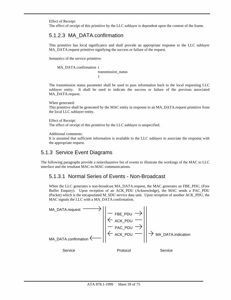
Effect of Receipt: The effect of receipt of this primitive by the LLC sublayer is dependent upon the content of the frame. 5.1.2.3 MA_DATA.confirmation
This primitive has local significance and shall provide an appropriate response to the LLC sublayer MA_DATA.request primitive signifying the success or failure of the request. Semantics of the service primitive:
MA_DATA.confirmation ( transmission_status )
The transmission status parameter shall be used to pass information back to the local requesting LLC sublayer entity. It shall be used to indicate the success or failure of the previous associated MA_DATA.request. When generated: This primitive shall be generated by the MAC entity in response to an MA_DATA.request primitive from the local LLC sublayer entity. Effect of Receipt: The effect of receipt of this primitive by the LLC sublayer is unspecified. Additional comments: It is assumed that sufficient information is available to the LLC sublayer to associate the response with the appropriate request.
5.1.3 Service Event Diagrams
The following paragraphs provide a nonexhaustive list of events to illustrate the workings of the MAC to LLC interface and the resultant MAC-to-MAC communications.
5.1.3.1 Normal Series of Events - Non-Broadcast
When the LLC generates a non-broadcast MA_DATA.request, the MAC generates an FBE_PDU, (Free Buffer Enquiry). Upon reception of an ACK_PDU (Acknowledge), the MAC sends a PAC_PDU (Packet) which is the encapsulated M_SDU service data unit. Upon reception of another ACK_PDU, the MAC signals the LLC with a MA_DATA.confirmation. MA_DATA.request
FBE_PDU
ACK_PDU
PAC_PDU
ACK_PDUMA_DATA.confirmation
Service Protocol Service
MA_DATA.indication
ATA 878.1-1999 Sheet 39 of 75

5.1.3.2 Normal Series of Events - Broadcast
When the LLC generates a broadcast MA_DATA.request, the MAC sends a PAC_PDU (Packet) which is the encapsulated M_SDU service data unit. Upon completion of the transmission, the MAC signals the LLC with a MA_DATA.confirmation. MA_DATA.request
PAC_PDU
MA_DATA.confirmation
Service Protocol Service
MA_DATA.indication
5.1.3.3 Exception: Nonexistent Node
In this example, the correspondent entity does not currently exist on the network medium. Therefore, no ACK_PDU is received by the sending node in response to the FBE_PDU (Free Buffer Enquiry). MA_DATA.request
FBE_PDU
MA_DATA.confirmation
Service Protocol Service
(no reponse)
5.1.3.4 Exception: No Free Buffer
When the corespondent node exists on the network medium but does not have a free buffer to receive the transmission, the node replies with a NAK_PDU (Negative Acknowledge). The transaction does not end at this point, however. Upon each reception of the token, the sending node retries the transaction until successful or commanded to abort the operation by the LLC. MA_DATA.request
FBE_PDU
Service Protocol Service
NAK_PDU
5.2 PHY to MAC Service
The services provided by the PHY layer allow the local MAC sublayer entity to exchange MAC data units with peer MAC sublayer entities. Note that all PHY data units have the duration of one symbol.
ATA 878.1-1999 Sheet 40 of 75

OSI
Layers > 2
Layer 2
Layer 1
878.1
PHYPhysical
MACMedium Access Control
Logical Link ControlLLC
NMTNetwork
Management
MIC
Medium
Figure 5.2
5.2.1 Interactions
The following primitives are defined for the MAC sublayer to request service from the PHY layer: PHY_DATA.request PHY_DATA.indication PHY_DATA.confirmation
All primitives described in this section are mandatory. 5.2.2 Detailed Service Specifications
All primitives are specified in an exemplary form only. Each service shall name the particular primitive and the required information that shall be passed between MAC sublayer and the PHY layer.
5.2.2.1 PH_DATA.request
This primitive defines the transfer of data from a local MAC sublayer entity to the station's PHY layer. Semantics of the service primitives:
PHY_DATA.request ( symbol )
The symbol specified shall be one of the following:
0 = binary zero 1 = binary one
When generated: The MAC sublayer shall send the PHY layer a PH_DATA.request every time the MAC sublayer has a symbol to output. Once the MAC sublayer has sent a PH_DATA.request to the PHY layer, it may not send another PH_DAT.request until it has received a PHY_DATA.confirmation from the PHY layer. Effect of Receipt: Upon receipt of this primitive, the PHY entity shall encode and transmit the symbol. When the PHY entity is ready to accept another PH_DATA.request it shall return to the MAC sublayer a PH_DATA.confirmation.
ATA 878.1-1999 Sheet 41 of 75

ATA 878.1-1999 Sheet 42 of 75
5.2.2.2 PH_DATA.indication
This primitive defines the transfer of data from the PHY layer to the MAC sublayer entity. Semantics of the service primitive:
PH_DATA.indication ( symbol )
The symbol shall be defined as one of the following:
0 = binary zero 1 = binary one
When generated: The PHY layer shall send the MAC sublayer a PH_DATA.indication every time the PHY layer decodes a symbol. This indication is sent once every symbol. Effect of Receipt: Upon receipt of this primitive, the MAC sublayer accepts a symbol from the PHY layer. 5.2.2.3 PH_DATA.confirmation
This primitive has local significance and shall provide an appropriate response to the MAC sublayer PH_DATA.request primitive signifying the acceptance of a symbol specified by the PH_DATA.request and willingness to accept another symbol. Semantics of the service primitive:
PH_DATA.confirmation ( transmission_status )
The transmission_status parameter shall be used to signify the transmission completion status. When generated: The PHY layer shall send the MAC sublayer PH_DATA.confirmation in response to every PH_DATA.request received by the PHY layer. The purpose of the PHY_DATA.confirmation is to synchronize the MAC sublayer data output with the data rate of the PHY layer medium. Effect of Receipt: The receipt of this primitive enables the MAC sublayer to send another PH_DATA.request to the PHY layer. Additional comments: The PHY layer provides synchronous service. That is, upon completion of a PH_DATA.confirmation it expects an immediate PH_DATA.request.

5.3 MAC to NMT Service
The services provided by the MAC layer to NMT allow the local NMT to control operation of the MAC layer.
OSI
Layers > 2
Layer 2
Layer 1
878.1
PHYPhysical
MACMedium Access Control
Logical Link ControlLLC
NMTNetwork
Management
MIC
Medium
Figure 5.3
5.3.1 Interactions
The following primitives are defined for the NMT to request services from the MAC layer: MA_CONTROL.request
The primitive described in this section is mandatory. 5.3.2 Detailed Service Specifications
This primitive is specified in exemplary form only. Service shall name the primitive and specify the information that shall be passed between MAC and NMT.
5.3.2.1 MA_CONTROL.request
This primitive shall be generated by the NMT to request the MAC layer to insert or remove itself from the logical token loop. Semantics of the control primitive:
MA_CONTROL.request ( control_action, station_address )
The control_action parameter shall be one of the following:
Insert - To cause insertion into the token loop. Remove - To cause removal from the token loop.
The station_address is the network address of this station, and is only meaningful when the control_action is “Insert”.
ATA 878.1-1999 Sheet 43 of 75

ATA 878.1-1999 Sheet 44 of 75
When generated: This primitive shall be generated by the NMT when the NMT requires insertion or removal of the station from the network. Effect of Receipt: The MAC layer shall take appropriate action to cause insertion or removal from the network.
5.4 PHY to NMT Service
The PHY does not provide any services to the NMT.

ATA 878.1-1999 Sheet 45 of 75
6. Physical Layer This section defines the physical (PHY) specifications. These include data symbol encoding and decoding, symbol timing, and data reliability. The specifications in this section are applicable to all station attachment specifications but are not specific to any particular station attachment specification.
6.1 Symbol Encoding
The PHY layer encodes and transmits the information presented to it at its MAC interface by the MAC sublayer. The information exchanged between the MAC and PHY are streams of binary zeros and ones. The data are presented in the Non-Return to Zero (NRZ format) for encoding as appropriate for the particular station attachment specification. 6.2 Data Signaling Rate
The basic data signaling rate is 2.5Mbps. The permitted tolerance for this signaling rate is ±0.01%. 6.3 Symbol Timing
The PHY layer recovers symbol timing based on information inherent in transitions of the received signal. This is facilitated by the use of frame formats with guaranteed, minimum periodicity of binary ones. The maximum allowed cumulative jitter in the received signal is ±50ns between any signal transitions within any single ISU. This cumulative jitter specification applies to the entire transmitter-to-receiver path during any network communication, including any repeaters or hubs along this path. Accordingly, the worst-case jitter characteristics on each individual transmitter, receiver, and repeater must be substantially better than this cumulative figure to ensure reliable network operation. Recommended practice is to limit any individual entity to less than 10% of the total jitter allowance. 6.4 Symbol Decoding
The PHY layer receives information presented to it and presents the decoded information to the MAC interface. The information exchanged between the MAC and PHY are streams of binary zeros and ones. The information is decoded as appropriate for the particular station attachment specification and presented to the MAC layer in the Non-Return to Zero (NRZ format).

ATA 878.1-1999 Sheet 46 of 75
7. Station Attachment Specifications – Electrical Cable
7.1 Scope
This section specifies the functional, electrical, and mechanical characteristics of the baseband electrical attachment to the 878.1 interconnect cabling. Compliance with the specifications in this chapter provides for compliance with methods /C, /T, /S, and /B as shown in section 1.2.4. Other methods of connections exist using electrical cable and do not preclude compliance with base 878.1. 7.2 Overview
The function of the 878.1 interconnect medium is to transport data symbols among all stations on the network. This communications medium may include a variety of different cable types, as well as hubs and/or repeaters, provided that the propagation, attenuation, and jitter specifications of this section are met. The medium interface cable, may be a single cable section or may include multiple sections of cable joined by connectors identical to the MIC. By definition, the MIC is the connector at which all transmitted and received signal specifications must be met. 7.3 Basic Signal Characteristics
7.3.1 Transmitted Signals
7.3.1.1 Data Signaling Rate
The basic data signaling rate is 2.5Mbps. The permitted tolerance for this signaling rate is ±0.01%. 7.3.1.2 Signal Level
The minimum magnitude of the transmitted signal, measured at the MIC with a 93Ω resistive termination, shall be not less than 15.4V and not more than 25.0V, peak to peak. The amplitude of the positive and negative portions of the dipulse shall be balanced to within 10%.
Transmit Signal Level Minimum Maximum
≥ 15.4V, p-p ≤ 25.0V, p-p 7.3.1.3 Symbol Encoding
A “1” bit is encoded as shown in Figure 7.1. A “0” bit is encoded as 400ns of no output from the transmitter. There are, therefore, only two signals transmitted: a 200ns dipulse followed by 200ns of silence representing a one bit and 400ns of silence representing a zero bit.

7.3.1.4 Signal Envelope
The basic signal shall be a single sine pulse of period 200ns followed by 200ns of silence as shown below. Figure 7-1 illustrates a sample waveform for informational purposes only. Compliant waveforms are determined by 7.3.1.6. In the diagram below, the functions are defined as follows.
ATA 878.1-1999 Sheet 47 of 75
2πt f(t)= sin 200ns for 0 ≤ t < 200ns 0 otherwise and
1 when 0 ≤ t < 100ns
g(t)= -1 when 100ns ≤ t < 200ns 0 when otherwise

g(t)
f(t)
100ns 100ns 200ns
Figure 7.1 Symbol Encoding for a “1” bit
7.3.1.5 Output Timing Jitter
The transmitter shall generate a signal stream with no more than ±2.5ns of jitter. The jitter is measured from the zero crossing of the first “1” bit of an ISU to the zero crossing of any other bit in the same ISU. 7.3.1.6 Measurement
Compliance with the above specification is determined by convolving a candidate waveform with a single 200ns sine pulse (2 volts peak to peak) and verifying that the amplitude of the result of the convolution at t=200ns is at least 15.4 volts. Refer to section A.3 for a recommended method to determine compliance.
7.3.2 Received Signals
7.3.2.1 Signal Delay
The total delay imposed by the medium (including cables as well as any hubs, repeaters, or other communication elements) may not exceed 31.0μs when using standard timeouts. The signal delays for other time-out settings are shown in the table below. Extended time-out level settings may not be mixed on a single network.
ATA 878.1-1999 Sheet 48 of 75

ATA 878.1-1999 Sheet 49 of 75
Signal Delay Limits Timeout Level Maximum Signal Delay
0* 1 2 3
31.0μs 134.9μs 274.1μs 552.5μs
* - Default value 7.3.2.2 Signal Attenuation
The maximum attenuation of the network signal, relative to the minimum transmitted amplitude, is 11dB.
Signal Attenuation 11dB maximum
7.3.2.3 Receiver Impedance
For star-topology systems, the receiver shall present an impedance of 93 ±25Ω. It is recommended that the receiver present an impedance of 93Ω ±15%. For bus-topology systems, the receiver shall present an impedance of at least 1.2KΩ regardless of the node's operating condition (power-on, power-off, transmit disabled, etc.).
Receiver Impedance Star Topology Bus Topology
93 ±25Ω ≥ 1.2kΩ 7.3.2.3 Signal Discrimination
The PHY shall generate a “1” symbol to the MAC with a mis-classification frequency less than 1 in 1012 when the input waveform is an attenuated (according to 7.3.2.2) and distorted (section 7.5) copy of the transmit waveform shown in Figure 7-1. The PHY shall generate a “0” symbol to the MAC with a mis-classification frequency less than 1 in 1012 for other impinging waveforms that do not exceed the maximum signal level defined in 7.3.1.2.
7.3.3 Coupling
The PHY shall connect to the medium using AC coupling.
7.4 System Considerations
878.1 supports two topologies: star wired and bus. The following sections describe the connection requirements.
7.4.1 Star Topology
Star topology is the connection from the PHY of one station directly to the PHY of another station or hub without intervening taps or branches. This connection shall be made using either coaxial or twisted-pair cable but shall be limited to one media type per segment. Each end of the media segment shall be properly terminated in the characteristic impedance by the PHY.

ATA 878.1-1999 Sheet 50 of 75
Required Termination
Coaxial Cable 93Ω ±1% Twisted-Pair 100Ω ±1%
The use of star topology on any given segment of a hub does not require the use of star topology on the other segments of the hub. 7.4.2 Bus Topology
Bus topology is the connection to a single segment of media more than one PHY.
7.4.2.1 Coaxial Cable
This section defines the rules for using coaxial cable in bus topology configurations. The minimum spacing between stations is 1 meter. The impedance presented to the medium by any given node must be greater than 1.2kΩ measured at 5MHZ. Each end of the bus segment must be terminated with a termination resistor of value 93Ω. No more that 8 stations may be connected to a single bus segment. The maximum length of any bus segment is 300 meters. The bus cable shall be connected to a station using a standard BNC T-connector.
Summary of Coaxial Cable Bus Topology Connection Requirements Minimum Spacing 1m Station impedance ≥1.2kΩ Segment termination value 93Ω Maximum number of stations per segment 8 Maximum bus segment length 300m
7.4.2.2 Twisted Pair Cable
This section defines the rules for using twisted pair cable in bus topology configurations. The minimum spacing between stations is 2 meters. The impedance presented to the medium by any given node must be greater than 1.2kΩ measured at 5MHZ. Each end of the bus segment must be terminated with a termination resistor of value 100Ω. No more that 8 stations may be connected to a single bus segment. The maximum length of any bus segment is 122 meters.
Summary of Bus Topology Connection Requirements Minimum Spacing 2m Station impedance ≥1.2kΩ Segment termination value 100Ω Maximum number of stations per segment 8 Maximum bus segment length 122m
7.4.3 Medium Timing Jitter
Intersymbol interference and reflections due to impedance mismatches and the effects of connection devices can introduce jitter to the propagated signal. No more than ±50ns of jitter shall be introduced to a test signal by either a coaxial or twisted pair cable segment. The test signal shall be a sequence of ISUs containing pseudo random data.

ATA 878.1-1999 Sheet 51 of 75
Medium Timing Jitter
±50ns maximum
7.5 Medium Characterization
The electrical medium supported by 878.1 are coaxial and twisted-pair cable. This section specifies the requirements of these cables.
7.5.1 Coaxial Cable Electrical Characteristics
For star and bus topology systems, the cable is of constant impedance, coaxial construction. The cable shall be terminated at each end in the characteristic impedance. Coaxial cable connectors shall be used for all connections. The following sections describe the electrical requirements of the cable. The specified cable is 93Ω coaxial cable. A typical cable that meets the following requirements is RG62.
7.5.1.1 Characteristic Impedance
The average characteristic cable impedance shall be 93±4Ω for RG62. 7.5.1.2 Attenuation
The attenuation of a 610m (2000 feet) of cable segment of RG62 shall not exceed 11dB measured at 5 MHZ. 7.5.1.3 Segment Propagation Delay
The cabling system used for a given network must meet the requirements of 7.3.2.1. The length of a cable segment is constrained by the attenuation afforded by the cable on that segment and the overall delay between any two stations on the network. The conventional practice of limiting the length of any cable segment to 2.44μs allows 11 cable segments (of 610m for RG62 or 460m of RG59) between any two stations while allowing 350ns propagation delay for each of the 10 intervening hubs.
7.5.2 Twisted-Pair Cable Electrical Characteristics
Twisted-pair medium is allowed for star and bus topology systems. The characteristics of the cable allowed are specified in IEEE 802.3i-1990 section 14.4. Also note the twisted-pair cable model in IEEE 802.3i-1990 Figure 14-7.
7.6 Safety and Grounding Requirements
All stations meeting this standard shall conform to either IEC Standard 380[10], IEC Standard 435[11], or IEC 950[12]. All exposed materials shall meet appropriate flammability requirements. Low smoke and fume materials shall be used as mandated by local requirements. 7.7 Medium Interface Connector (MIC)
The Medium Interface Connector is medium dependent, as detailed below.

7.7.1 Coaxial Cable
The MIC for use with coaxial cable is a conventional female BNC per MIL-STD-348A. The signal is transmitted such that the waveform is measured at the center conductor with respect to the shield. 7.7.2 Unshielded Twisted Pair Cable
The MIC for use with unshielded twisted pair cable (telephone cable) is a conventional RJ11C or RJ45 (reference ISO 8877). The signals are assigned to pins as shown in the table below. The waveform is measured at LINE+ with respect to LINE-.
Modular Connector Pin Assignments 4-Contacts 6-Contacts 8-Contacts
Pin Usage Pin Usage Pin Usage 1 1 1 2 LINE- 2 2 3 LINE+ 3 LINE- 3 4 4 LINE+ 4 LINE- 5 5 LINE+ 6 6 7 8
ATA 878.1-1999 Sheet 52 of 75
Figure 7.2 − RJ45 Connector

ATA 878.1-1999 Sheet 53 of 75
8. Station Attachment Specifications – Fiber Optic Cable
8.1 Scope
This section specifies the functional, optical, and mechanical characteristics of the baseband fiber optic attachment to the 878.1 interconnect cabling. Compliance with the specifications in this chapter provides for compliance with methods /M, /F and /S as shown in section 1.2.4. Other methods of connections exist using fiber optic cable and do not preclude compliance with base 878.1. 8.2 Overview
The function of the 878.1 interconnect medium is to transport data symbols among all stations on the network. This communications medium may include a variety of different cable types, as well as hubs and/or repeaters, provided that the propagation, attenuation, and jitter specifications of this section are met. The medium interface cable may be a single cable section or may include multiple sections of cable joined by connectors identical to the MIC. By definition, the MIC is the connector at which all transmitted and received signal specifications must be met. 8.3 Basic Signal Characteristics
8.3.1 Transmitted Signals
8.3.1.1 Data Signaling Rate
The basic data signaling rate is 2.5Mbps. The permitted tolerance for this signaling rate is ±0.01%. 8.3.1.2 Signal Level
The tables below shows the range of peak optical power measured with a large-area detector at the end of one meter of fiber optic cable. More power is coupled into a fiber as its diameter and numerical aperture (NA) is increased. These measurements are made when the optical transmitter is forced into being continuously on. Data has been provided for both 850nm and 1300nm center wavelengths. Fiber size is referenced by its core/cladding diameter.
Transmitted Peak Optical Power 850nm center wavelength
Fiber Size (µm)
NA
Minimum (dBm)
Maximum (dBm)
62.5/125 0.27 -15.0 -9.0

Transmitted Peak Optical Power 1300nm center wavelength
Fiber Size (µm)
NA
Minimum (dBm)
Maximum (dBm)
single mode 62.5/125
⎯ 0.27
-22.0 -17.5
-17.0 -11.5
8.3.1.3 Symbol Encoding
A “1” bit is encoded as shown in Figure 8.1. A “0” bit is encoded as 400ns of no output from the transmitter. There are, therefore, only two signals transmitted: either a 100 or 200ns return to zero (RTZ) pulse followed by a 300ns or 200ns of silence respectively representing a one bit, or 400ns of silence representing a zero bit. 8.3.1.4 Signal Envelope
The basic signal shall be single unipolar pulse of either 100 or 200ns in duration returning to zero for the remaining duration of the 400ns interval. Figure 8-1 illustrates a sample waveform. In the diagram below, the functions are defined as follows:
1 when 0 ≤ t ≤ 200ns g(t)= 0 when otherwise
ATA 878.1-1999 Sheet 54 of 75
It is recommended that the drive signal for the required output be derived from P1 or the logical sum of P1 and P2. P1 (pulse 1) and P2 (pulse 2) refer to the non-overlapping pulses used to drive the coaxial transceiver and are referenced in traditional ARCNET documentation. The use of either of these signals ensures the jitter requirements of 8.3.1.5 are met. 100ns 100ns 200ns
Figure 8.1 − Symbol Encoding for a “1” bit 8.3.1.5 Output Timing Jitter
The transmitter shall generate a signal stream with no more than ±2.5ns of jitter. The jitter is measured from the leading edge of the first “1” bit of an ISU to the leading edge of any other bit in the same ISU. 8.3.1.6 Measurement
To measure the output power level, the transmitter must be forced to the “1” state continuously and the output measured using an optical power meter attached to the MIC using one meter of corresponding size fiber optic cable.

ATA 878.1-1999 Sheet 55 of 75
8.3.2 Received Signals
8.3.2.1 Signal Delay
The total delay imposed by the medium (including cables as well as any hubs, repeaters, or other communication elements) may not exceed 31.0μs when using standard timeouts. The signal delays for other timeout settings are shown in the table below. Extended timeout level settings may not be mixed on a single network.
Signal Delay Limits Timeout Level Maximum Signal Delay
0* 1 2 3
31.0μs 134.9μs 274.1μs 552.5μs
* - Default value It should be noted that the propagation delay for fiber optic cable (5ns/m) is more than the delay experienced from an equivalent length of coaxial cable (4ns/m). If comparisons are being made between the two types of cables for delay calculations, a one meter length of fiber optic cable is equivalent to 1.25 meters of coaxial cable in terms of delay. Since fiber optic segments can span much longer distances than coaxial cable, it is important to calculate the overall delay of the network to ensure that extended timeouts are not required. 8.3.2.2 Receiver Sensitivity
Two types of receiver designs are specified. The short wave (850nm) design is recommended for general purpose installations of nominal distance. The long wave (1300nm) design is recommended for those installations requiring greatest distance.
Minimum Receiver Sensitivity Fiber Size
(µm) Sensitivity
850nm (dBm) Sensitivity
1300nm (dBm) Single mode
62.5/125 ⎯
-25.4 -35.0 -35.0
8.4 System Considerations
8.4.1 Star Topology
Star topology is the connection from the PHY of one station directly to the PHY of another station or hub without intervening taps or branches.
Fiber optic networks will only be configured in a star topology. The mixing of coaxial or twisted-pair segments with fiber optic segments is possible with the use of hubs. 8.4.2 Link Loss Budget
The total power lost from the transmitter to the receiver is the link loss which includes the cable attenuation, connector losses and splices. The sum of these losses (the link loss) must be less than the optical power budget. The difference between the optical power budget and the link loss represents the margin in the system. It is recommended that the minimum margin be no less than 3dB.

ATA 878.1-1999 Sheet 56 of 75
8.4.3 Maximum Segment Length
Based upon the optical power budget and acceptable level of margin, maximum segment lengths have been specified for various core sizes and operating center wavelengths. These segments assume a maximum attenuation factor (per 8.5.1) and connectors only at the end of the segment. No splices were considered. This distance may need to be reduced if the actual link loss calculation exceeds the above assumptions.
Maximum Segment Length
Fiber Size
(µm)
Length
(850nm)
Max Cable Attenuation
(dB/km)
Length
(1300nm)
Max Cable Attenuation
(dB/km) Single mode
62.5/125 ⎯
2000m ⎯
3.75 10000m 10000m
1.0 1.5
8.4.4 Medium Timing Jitter
Intersymbol interference can introduce jitter to the propagated signal. No more than ±50ns of jitter shall be introduced to a test signal by a fiber optic segment. The test signal shall be a sequence of ISUs containing pseudo random data.
Medium Timing Jitter ±50ns maximum
8.4.5 Overdrive
On short cable installations with high levels of transmitter output power, it is possible to overdrive the receiver causing excessive jitter. If the receiver design does not have adequate dynamic range, means must be provided by the equipment vendor to reduce transmitter power to an acceptable range.
8.5 Medium Characterization
The fiber optic cabling between a station and another station or between a station and a hub requires a single pair (duplex cable). The half-duplex nature of the 878.1 protocol does not preclude the use of simplex cabling (one fiber) and corresponding transceivers. The use of this cable is acceptable as long as an overdrive condition is not experienced with short segment lengths.
8.5.1 Attenuation
Fiber optic cable attenuation factors shall not exceed those listed in the following table.
Fiber Optic Cable Attenuation
Fiber Size (µm)
Max Attenuation 850nm
(dB/km)
Max Attenuation 1300nm (dB/km)
Single mode 62.5/125
⎯ 3.75
1.0 1.5
8.5.2 Segment Propagation Delay
The cabling system used for a given network must meet the requirements of 8.3.2.1. The length of a cable segment is constrained by the attenuation afforded by the cable on that segment and the overall delay between any two stations on the network.

ATA 878.1-1999 Sheet 57 of 75
When calculating the overall propagation delay of a network or the propagation delay of individual fiber optic segments, use the maximum propagation delay factor for fiber optic cable.
Maximum Propagation Delay
5ns/m
8.6 Safety and Grounding Requirements
All stations meeting this standard shall conform to either IEC Standard 380[10], IEC Standard 435[11], or IEC 950[12]. All exposed materials shall meet appropriate flammability requirements. Low smoke and fume materials shall be used as mandated by local requirements.
8.7 Medium Interface Connector (MIC)
The Medium Interface Connector is medium dependent, as detailed below. Either connector can be used in compliance to the standard; however, the use of an alternate connector does not preclude compliance to the standard.
8.7.1 SMA-Type Connector
The SMA-905 and SMA-906 type connector socket is indicated by compliance method /M. For duplex operation the MIC will consist of two connector sockets. 8.7.2 ST-Type Connector
The BFOC/2.5 connector socket (commonly known as an ST-type connector) is indicated by compliance method /F. For duplex operation the MIC will consist of two connector sockets.

ATA 878.1-1999 Sheet 58 of 75
9. Active Hub Specification
9.1 Scope
This section defines the functional characteristics of active hubs for use with star topology 878.1. This section does not define the electrical or mechanical characteristics of the hub. Active hubs may be employed with star topology networks, using any form of cabling or other interconnect media, which meet the attachment specifications of this standard. Passive hubs are considered part of the interconnect media, and are not covered herein, because they merely attenuate the signal while splitting it among several ports. 9.2 Overview
An active hub is a device which provides for selective connection of groups of cables, with each cable connecting to a station or to another active hub. The active hub implements cable segment isolation, wiring concentration, signal repeating, and echo cancellation. Under ordinary circumstances active hubs do not interpret the signals which they repeat. However, active hubs which provide features such as network management or media type conversion may be implemented as a superset of the functionality defined herein. 9.3 Active Hub Finite State Machine
The active hub imposes a priority upon its ports, based upon the first port from which it detects incoming activity during any particular signal repeating event. Assigning a fixed set of relative priorities among these ports is acceptable for resolving incoming activity conflicts which occur due to detecting input signals simultaneously on two or more ports. However, a strict first-come, first-serve priority must be used to arbitrate between activity arriving in sequence on different ports. An N-port active hub employs a finite state machine with N+1 states. One of these states is an idle state, where the receivers are enabled on all ports and the transmitters are disabled on all ports. As soon as activity is detected on any port, a transition is made to one of the other N states, based upon the port from which activity was first detected. The resulting state is a state in which the receiver of the port from which the activity was detected remains enabled, while the receivers of all other ports are disabled; and with transmitters enabled on all ports other than the port from which the activity was detected. Once this active state is entered, all signals received on the (enabled) receive port are re-transmitted, approximately simultaneously, on all other ports. Note that in the ordinary circumstance, this regeneration of the signals does not involve re-timing of the signals. Therefore, bit jitter accumulates from hub to hub, thereby limiting the number of hubs which may be used on any path between stations. Once any particular active state has been entered, the hub remains in that state until a predefined time-out period, the hub unlatch delay (THU) has elapsed with no receive activity detected. Upon THU time-out, the hub returns to the idle state. The duration of THU provides for canceling of echoes from unterminated cables. This is accomplished because THU is longer than the worst case, round-trip delay to the far end of a maximum length cable. This prevents echoes from the far end of a cable from being mistakenly interpreted as incoming activity. THU is shorter than the minimum interframe gap, so as to always return the hub to the idle state prior to the beginning of the next frame. The diagram below shows a typical finite state machine for an active hub.

A legend of FSM notation appears in section 1.3.
state 0:Idle
01No receive activity
All receivers enabledAll transmitters disabled
Receive activity on port 1
Only port 1 receiver enabledAll but port 1 transmitter enabled
02
state 1:Port 1 active
12
Any receive activity
All but port 1 transmitter enabled
11Only port 1 receiver enabledNo receive activity for THU
All transmitters enabledAll receivers enabled
state 2:Port 2 active
22
Any receive activity
All but port 2 transmitter enabled
21Only 2 port receiver enabled
03 Receive activity on port 2
Only port 2 receiver enabledAll but port 2 transmitter enabledNo receive activity for THU
All receiver enabledAll transmitters enabled
Identical active states used for each additional port
Figure 9.1 − Hub Finite State Machine 9.4 Hub Timing
9.4.1 Unlatch Delay
The hub unlatch delay, THU, must be between 5.0μs and 12.0μs. However, it is highly recommended that the time be set with a minimum of 5.2μs and a maximum of 7.8μs. 9.4.2 Bit Jitter
When regenerating the waveform it is necessary that the timing of all the signals within any given ISU not vary from the proper position, relative to the first bit of the ISU (or from each other), by more that 2.5ns. This permits the use of up to 10 active hubs in the path between any pair of stations without degradation of the bit error rate. Hubs with greater than this amount of bit jitter may be used if this fact is documented and the permissible number of hubs per path are appropriately reduced. However, “878.1/S” compatibility requires that the full 10-hub limit be met.
ATA 878.1-1999 Sheet 59 of 75

ATA 878.1-1999 Sheet 60 of 75
9.4.3 Throughput Delay
The delay from receiving a signal on the active input port to re-transmitting that signal on all other ports must not exceed 350ns to permit the use of up to ten hubs and eleven 610m segment lengths of coaxial cable between a pair of stations. Hubs with larger throughput delays may be used if this fact is documented. Under no circumstances should the sum of hub and cable delays exceed 31μs when operating at the default timeout. However, “878.1/S” compatibility requires that the full 10-hub limit be met.

ATA 878.1-1999 Sheet 61 of 75
10. System Code Assignments The system code identifies the usage, and by implication the format, of the INFO field of data packet frames. Unambiguous system codes must be used in order to permit multiple high-level protocols to be used concurrently on a single 878.1 network. To prevent conflicting system code assignments, system code values are assigned by the ARCNET Trade Association Standards Committee upon request. Since system codes are a scarce resource, system codes will only be issued when the protocol requirement cannot be met using one of the already assigned codes. The conventional system code is a one-byte value permitting 256 unique codes. A two-byte format is also defined using 62 of the one-byte values as escape codes. Two byte system codes are defined such that the first byte of the INFO field is used in conjunction with the SC field to determine the protocol type. System code 0x80 has been set aside for use as a temporary, diagnostic system code. This system code can be used by any system for any purpose. Therefore, all systems should be able to accept these frames without causing system errors. To obtain a system code or to view the current system code assignments contact the ARCNET Trade Association.

11. Alternate Physical Layer and Station Attachment Specification – Balanced Digital Multipoint System
11.1 Scope
This section specifies the functional, electrical, and mechanical characteristics of the alternate baseband electrical attachment to the 878.1 interconnect cabling. Referred to in this section as Balanced Digital Multipoint System, it is commonly known as EIA-485. Compliance with the specifications in this chapter provides for compliance with method /E as shown in section 1.2.4. Other methods of connections exist using electrical cable and do not preclude compliance with base 878.1. 11.2 Overview
The function of the 878.1 interconnect medium is to transport data symbols among all stations on the network. This communications medium may include a variety of different cable types, as well as hubs and/or repeaters, provided that the propagation, attenuation, and jitter specifications of this section are met. The medium interface cable may be a single cable section or may include multiple sections of cable joined by connectors identical to the MIC. By definition, the MIC is the connector at which all transmitted and received signal specifications must be met. The intent of this section is to identify the minimum compliance level of the EIA-485 alternate physical layer and station attachment specification. The EIA-485 standard does not address all station attachment issues and there are, therefore, several variations of successful implementations of the standard. This section will address all station attachment issues but will make recommendations where strict compliance is unnecessary. 11.3 Basic Signal Characteristics
Information in the following section has been extracted from the ANSI/TIA/EIA-485-A [24]standard and has been reprinted here for convenience. Refer to the standard itself for a more concise description of the requirements of the standard. Not all requirements of the ANSI/TIA/EIA-485-A standard will be restated in this section; however, it is the intention that all requirements of this standard be met. For simplicity the standard will be referenced as 485. A typical 485 network is shown in figure 11.1. For this section, the terms driver, generator, transceiver and transmitter all refer to a device that sources signal onto the medium.
Figure 11.1 − Balanced Digital Multipoint System
ATA 878.1-1999 Sheet 62 of 75

11.3.1 Transmitted Signals
11.3.1.1 Data Signaling Rate
The basic data signaling rate is 2.5Mbps. The permitted tolerance for this signaling rate is ±0.01%. Alternate signaling rates are possible with 485 and it is the responsibility of the vendor to identify which data rates are supported besides the basic data signaling rate. 11.3.1.2 Signal Level
A generator must be capable of driving two 120 ohm terminating resistors and 32 unit loads representing 32 stations while operating over a common mode range of –7 volts to +12 volts. The minimum differential output voltage |Va-Vb| is 1.5 volts and the maximum is 5.0 volts. The test circuit is shown in Figure 11.2
Transmit Signal Level |Va-Vb| Minimum Maximum 1.5 volts 5.0 volts
Figure 11.2 – Differential output voltages with common-mode loading 11.3.1.3 Symbol Encoding
A “1” bit is encoded as shown in Figure 11.3. A “0” bit is encoded as 400ns of a continuous state of Va > Vb which implies that the differential voltage Va – Vb > 0. 11.3.1.4 Signal Envelope
The basic signal shall be a return to zero (RTZ) pulse of 200ns in duration returning to the quiescent state for an additional 200ns. In the diagram below, the functions are defined as follows:
-1 when 0 ≤ t ≤ 200ns g(t)= Va-Vb 1 when otherwise
ATA 878.1-1999 Sheet 63 of 75

Figure 11.3 – Symbol Encoding for a “1” bit
11.3.1.5 Output Timing Jitter
The transmitter shall generate a signal stream with no more than ±2.5ns of jitter. The jitter is measured from the zero crossing of the first “1” bit of an ISU to the zero crossing of any other bit in the same ISU.
11.3.2 Received Signals
11.3.2.1 Signal Delay
The total delay imposed by the medium (including cables as well as any hubs, repeaters, or other communication elements) may not exceed 31.0μs when using standard timeouts. The signal delays for other timeout settings are shown in the table below. Extended timeout level settings may not be mixed on a single network.
Signal Delay Limits Timeout Level Maximum Signal Delay
0* 1 2 3
31.0μs 134.9μs 274.1μs 552.5μs
* - Default value 11.3.2.2 Receiver Impedance
The receiver shall present an impedance of not less than 12KΩ regardless of the node’s operating condition (power-on, power-off, transmit disabled, etc.).
Receiver Impedance ≥12KΩ
11.3.3 Coupling
The PHY shall connect to the medium using DC coupling.
ATA 878.1-1999 Sheet 64 of 75

ATA 878.1-1999 Sheet 65 of 75
11.3.4 Receiver Sensitivity
The receiver differential input voltage shall be no less than +200 mV. Any voltage less than the minimum specified could cause the receiver output to be unpredictable.
Receiver Sensitivity Minimum +200 mV
11.4 System Considerations
EIA-485 networks are wired in a bus topology. Requirements such as cable type, grounding, shielding and fail-safe bias must be met.
11.4.1 Twisted-Pair Cable
In a balanced digital multipoint system, twisted-pair cable is used as the medium between station attachment units. No single cable type is specified; however, the following characteristics must be met.
11.4.1.1 Characteristic Impedance
The characteristic impedance of the twisted-pair cable should be no less than 100 ohms and no greater than 150 ohms when measured at a frequency of 1 Mhz. Care should be exercised when utilizing a cable with a characteristic impedance less than 120 ohms since DC terminating this type of cable could cause excessive loading of the EIA-485 transmitters. Nominal characteristic impedance of 120 ohms is recommended but not required.
Characteristic Impedance Minimum Nominal Maximum
100Ω 120Ω 150Ω 11.4.1.2 Capacitance
In order to comply with the basic data rate of 2.5Mbps, low capacitance twisted-pair cable is required. The differential capacitance (conductor to conductor) shall be less than 42 pf/meter. The capacitance between a conductor and all conductors tied to shield (on shielded cables) shall be less than 76 pf/meter. For data rates above the basic data rate of 2.5Mbps, cables with even lower capacitance may be required. For data rates below the basic data rate of 2.5Mbps, cable capacitance values could possibly be relaxed. Characterization of capacitance requirements at data rates other than 2.5Mbps have not been made.
Cable Capacitance Differential Common Mode < 42 pf/m < 76 pf/m
11.4.1.3 Shielding
Either shielded or unshielded twisted-pair cable can be used. However, the EMC requirements of the installation may dictate that EMC compliance is only ensured when shielded cable is used.

11.4.1.4 Conductor Diameter
The minimum conductor wire size should be not smaller than 24 AWG. This translates to a conductor diameter of >0.22mm2.
Conductor Diameter >0.22mm2
11.4.2 Fail-safe Bias
During idle states when no transmitters are active, the medium floats allowing the voltage across the medium to possibly collapse below the receiver input sensitivity of ±200mV. It is during this time that a receiver could falsely recognize data. To avoid this possibility, fail-safe bias must be applied to ensure that the idle medium will maintain a differential voltage |Va-Vb| > 200mV. Refer to figure 11.4 for a recommended circuit for supplying fail-safe bias.
Bias Voltage >200mV
Figure 11.4 – Recommended fail-safe bias circuit
11.4.2.1 Source of Fail-Safe Bias
The power source for the fail-safe bias can be derived from a separate power supply (or power supplies) or from the station attachment units themselves. In either case, the power source shall be +5 volts ±5%. If the power is being supplied by the station attachment unit, a disconnecting means on the station attachment unit must be provided in order to disable fail-safe bias from the medium. However, a minimal amount of fail-safe bias is allowed to remain as long as the bias resistors are equal to or greater than 47k ohms. 11.4.2.2 Value of Bias Network
The value of the bias network depends upon the source voltage (+5 volts) and the value of the two terminating resistors at each end of the network. The amount of bias current generated by the bias network should be sufficient to develop at least +200mV of bias to the medium at any point. This is the absolute minimum amount of bias required. Additional bias voltage would guard against any underdamped oscillations that may dip below the +200mV threshold. Care should be exercised to ensure that the value of the bias network is not too low as to excessively load the EIA-485 transmitters.
ATA 878.1-1999 Sheet 66 of 75

ATA 878.1-1999 Sheet 67 of 75
11.4.2.3 Bias Network Point of Application
Although the bias network could be located at any point along the medium, it is best applied at one end of the medium segment. In the case of short segment lengths, the DC resistance of the segment may have little impact on the loss of bias due to a voltage divider effect at the far end of the segment. In the case of long segments, the DC resistance has a significant impact in which case it may be best to apply bias at each end of the segment to eliminate the impact of DC cable resistance reducing bias voltage. 11.4.2.4 Combination Bias and Termination
The value of the bias network will load down the terminating resistor thereby reducing the effective termination resistance. By including the value of the bias resistors into the calculation of the terminating resistor, a combination bias and terminating resistor network can be developed. The Thevenin equivalent of the circuit should have an open circuit voltage of twice the desired bias and an output impedance equal to the characteristic impedance of the cable. This same network could then be applied at the far end of the medium segment thereby providing bias and termination at each end of the segment.
11.4.3 Termination
Since an EIA-485 transmitter may be located in the middle of the medium segment, termination must be applied at each end of the segment. A terminating resistor or a termination network must match the characteristic impedance of the medium with a tolerance of +20%. The minimum value of terminating resistor or terminating network resistance must not be less than 120 ohms otherwise the maximum number of stations (11.4.4) specification would need to be compromised.
Terminating Resistance > 120 ohms
11.4.4 Maximum Number of Stations
The maximum number of stations per medium segment with terminating resistors no less than 120 ohms each shall be 32. The total number of stations per network can be greater with the use of hubs. Each hub connection counts as a station in terms of segment loading.
Number of Stations maximum
32/segment 11.4.5 Maximum Segment Length
The maximum length of a medium segment operating at the basic data rate of 2.5Mbps is 275 meters. At this length a total of 32 stations can be supported.
Segment Length maximum
275m 11.4.6 Minimum Distance Between Stations
The minimum distance between stations is based upon the rise and fall times of the transmitter and the propagation delay to the nearest receiver. The distance between the transmitter and receiver must be no closer in time than half the rise (or fall) time (10%-90%) of the transmitter. For a 10ns transmitter, the receiver must

ATA 878.1-1999 Sheet 68 of 75
be 5ns or greater distant. With a medium propagation delay of 5ns/meter, the minimum station distance is one meter.
Distance Between Stations minimum
1m
11.5 Safety and Grounding Requirements
All stations meeting this standard shall conform to either IEC Standard 380[10], IEC Standard 435[11], or IEC 950[12]. All exposed materials shall meet appropriate flammability requirements. Low smoke and fume materials shall be used as mandated by local requirements.
11.5.1 Signal Common
Proper operation of the interface circuits requires the presence of a signal common path between the circuit commons of the equipment connected along the medium. Refer to ANSI/TIA/EIA-485-A for guidance in providing this path. 11.5.2 Protection Circuitry
In order to protect the interface circuits from excessive common mode voltages, protection circuitry can be added from each signal conductor on the medium to either a common reference point or earth ground. This is usually accomplished with a signal diode in series with a transient absorbing device. The total capacitance introduced by the protection circuitry should not exceed 10pf from each conductor to either a common point or earth ground per station when operating at 2.5Mbps and above.
11.6 Medium Interface Connector (MIC)
The Medium Interface Connector is medium dependent, as detailed below. Due to the flexibility in connector selection, no single connector style is specified. If the equipment vendor elects not to use any of the following connectors, the pin assignments for the connector used must be specified.

11.6.1 Telephone Style
A MIC for use with unshielded or shielded twisted-pair cable is a conventional RJ11C or RJ45 (reference ISO 8877). The signals are assigned to pins as shown in the table below. The waveform is measured at LINE+ with respect to LINE-. LINE+ corresponds to conductor A/A’ and LINE- corresponds to B/B’ in figure 11.1. In the idle state LINE+ is more positive with respect to LINE-.
Modular Connector Pin Assignments 4-Contacts 6-Contact 8-Contacts
Pin Usage Pin Usage Pin Usage 1 1 1 2 LINE- 2 2 3 LINE+ 3 LINE- 3 4 4 LINE+ 4 LINE- 5 5 LINE+ 6 6 7 8
ATA 878.1-1999 Sheet 69 of 75
Figure 11.5 − RJ45 Connector
11.6.2 Subminiature D Connector
The 9 pin subminiature D connector receptacle (popularly known as the DB9) can serve as the MIC. The pin assignments are noted in the table below. The MIC should be a receptacle (with female pins). Figure 11.6 identifies pin orientation. Power provisions must be made available to accommodate a fail-safe bias network. Refer to figure 11.1 for signal definitions. It is recommended that the connector housing itself provide a wide area shield connection in order to accommodate a shielded mating housing.
DB9 Pin Assignments Pin Description 1 Shield 2 3 B/B’ 4 5 Common Ground 6 +5 volts 7 8 A/A’ 9

Figure 11.6 − Subminiature D Connector
ATA 878.1-1999 Sheet 70 of 75

ATA 878.1-1999 Sheet 71 of 75
Annex
Additional Reference Material
(This annex is not a part of the ATA 878.1 Local Area Network Standard but is included for informational purposed only.) [1] Peter H. Halpern, "Trigonometric Pulse-Forming Networks Revisited", IEEE Transactions on Circuit Theory, Jan.
1972 [2] ANSI/NFPA 70-1987, National Electrical Code1
[3] ANSI/UL 114-1982, Safety Standard for Office Applications and Business Equipment [4] ANSI/UL 478-1979, Safety Standard for Electronic Data-Processing Units and Systems [5] ECMA-97(1985), Local Area Networks Safety Requirements2
[6] IEEE 802.3i-19903
[7] CISPR Publication 22 (1985), Limits and Methods of Measurement of Radio Interference Characteristics of Information Technology Equipment.1
[8] IEC Publication 96-1 (1971) (3rd Edition), Radio Frequency Cable, Part 1: General Requirements and Measuring Methods.1
[9] IEC Publication 169-8 and 169-16, Radio Frequency Coaxial Connections with Screw Coupling, 50W (Type BCN and N).
[10] IEC Publication 380 (1985) (3rd Edition), Safety of Electrically Energized Office Machines. [11] IEC Publication 435 (1983) (2nd Edition), Safety of Data Processing Equipment. [12] IEC Publication 950 (1986), Safety of Information Technology Equipment Including Electrical Business
Equipment. [13] ISO 2382/09, The Information Processing Vocabulary, IPV, Section 09: Data Communication4
[14] ISO 7498, Information Processing Systems - Open System Interconnection - Basic Reference Model, November 15, 1984
[15] MIL-STD-348A, Radio Frequency Connector Interfaces5
[16} Comparing EIA-485 and EIA-422-A Line Drivers and Receivers in Multipoint Applications, AN-759, National Semiconductor, Feb. 1991
[17] Data Transmission Lines and Their Characteristics, AN-806, National Semiconductor, Feb. 1996. [18] Reflections: Computations and Waveforms, AN-807, National Semiconductor, March 1992.[19] Long Transmission
Lines and Data Signal Quality, AN-808, National Semiconductor, March 1992 [20] Failsafe Biasing of Differential Buses, AN-847, National Semiconductor, July 1992 [21] A Comparison of Differential Termination Techniques, AN-908, National Semiconductor, August 1993 [22] A Practical Guide to Cable Selection, AN-916, National Semiconductor, October 1993 [23] The Practical Limits of RS-485, AN-979, National Semiconductor, March 1995 [24] Electrical Characteristics of Generators and Receivers for Use in Balanced Digital Multipoint Systems, TIA/EIA-
485-A, Telecommunications Industry Association, March 1998 [25] Applications Guidelines for TIA/EIA-485-A, TSB89, Telecommunications Industry Association, June 1998
1 All ANSI and CISPR documents are available from the Sales Department, American National Standards Institute, 1430 Broadway, New York, NY 10018. 2 ECMA documents are available from European Computer Manufacturers Association, 114 Rue du Rhone, 1204 Geneva, Switzerland. 3 IEEE documents are available from the Service Center, Institute of Electrical and Electronic Engineers, 445 Hoes Lans, PO Box 1331, Piscataway, NJ 08855-1331. 4 ISO documents are available in the US from the Sales Department, American National Standards Institute, 1430 Broadway, New York, NY 10018, USA. 5 MIL-STD documents are available from: DODSSP, Standardization Document Order Desk, 700 Robbins Avenue, Bldg. 4D, Philadelphia, PA 19111-5094, FAX (215) 697-2978

ATA 878.1-1999 Sheet 72 of 75
[26] Commercial Building Telecommunications Cabling Standard, TIA/EIA-568-A, Telecommunications Industry Association, October 1995
[27] Information technology⎯Telecommunications and information exchange between systems−Twisted pair multipoint interconnections, ISO/IEC 8482-1993, ISO/IEC, 1993
[28] Profibus Standard, part 1, DIN 19245, Profibus Trade Organization, 1993. [29] Fiber Optic Active and Passive Star-Based Segments, Type 10BASE-F (sections 15-18), 802.3 supplements,
Institute of Electrical and Electronics Engineers, Oct. 1993 [30] ARCNET Designer’s Handbook, 61610, Datapoint Corporation, 1988. [31] ARCNET Cabling Guide, 51087, Datapoint Corporation, 1988 [32] ARCNET’s Already Flexible Physical Layer Enhanced with Several EIA-485 Varients, FieldComms USA, 1997 [33] RS-485 Cabling Guidelines for the COM20020 Universal LAN Controller, TN7-5, Standard Microsystems Corp.,
May 1994 [34] ARCNET−The universal, realtime capable fieldbus solution, ARCNET Users Group, 1998

ATA 878.1-1999 Sheet 73 of 75
Appendix A
Recommended Practices
(This appendix is not a part of the ATA 878.1 Local Area Network Standard but is included for informational purposed only.)
A.1 Receiver Filter
Many existing 878.1 receivers are implemented using a matched filter[1]. The matched filter is designed to provide a maximum response for an input sine pulse of period τ = 200ns. The output from a matched filter designed as described above and stimulated with a 200ns sine pulse produces an output that is the convolution of the input sine pulse and a pure 200ns sine pulse. The 878.1 receivers that employ this technique then threshold this output to determine the transmitted symbol. Component tolerances are as follows: resistors ±1%, capacitors ±5%, and inductors ±10%. A.2 LLC Issues
A.2.1 Duplicate PAC Reception
After the transmission of a non-broadcast PAC frame, the MAC sets the TMA flag if the destination MAC responded with an ACK frame. The lack of a response to a PAC within TRP or a response from the destination MAC of a NAK frame causes the local MAC to clear the TMA flag. The use of the TMA flag by the LLC is optional but can be used to verify delivery of frames. Since the lack of a response to the PAC frame is an indication that the destination MAC was unable to copy the frame (perhaps due to line noise during the PAC causing an FCS error), it is often the policy of the LLC to retry transmissions in which the TMA flag is not set. A side effect of this retry policy is that it is possible for a PAC frame to be delivered more than once to the destination LLC. This condition can occur when the ACK from the destination MAC is lost (perhaps due to noise or a reconfiguration burst) causing the TMA to remain clear. Since the ACK from the destination is transmitted concurrently with issuing the MA_DATA.indication, the destination LLC begins processing the frame. The local MAC then retransmits the frame using the above retry policy which then causes a second copy of the frame to be received at the destination LLC. A recommended practice to deal with this possibility of duplicate PAC reception is to include a transmission sequence number in an LLC (or higher) header and to discard successive PAC receptions with the same sequence value. In many cases a single bit is sufficient for sequencing. A.2.2 LLC Retry on TA without TMA
The occurrence of a transmission of a non-broadcast PAC which ends with the TA flag set and the TMA flag clear indicates either an attempt to transmit to a non-existent destination or a transmission that was received in error or whose ACK was received in error. Recommended practice is for LLC to retry such transmissions up to 5 times before abandoning the attempt due to non-occurrence of TMA flag set.

A.2.3 Automatic MAC Retry on NAK to an FBE
In the case where the local MAC transmits an FBE frame to a destination MAC and the destination MAC responds with a NAK frame, then the local MAC leaves the TA flag clear. The effect of this is that the transmission is retried upon the reception of the next token to the local MAC. This action is repeated indefinitely or until the LLC issues a command to terminate the transmission. A recommended practice to deal with this possibility of indefinite retries is to time the transmission activity at the LLC and terminate the transmission attempt after approximately 100 milliseconds or approximately 128 NAKed FBEs.
A.3 Compliance Using Convolution
To verify transmitter waveform compliance a convolution is called for in section 7.3.1.6. There are a number of methods that can be used to accomplish this task. The following circuit is an example of one such method. The following circuit is derived from Halpern[1]. The matched filter designed according to the following parameters.
Filter Design Criteria Impedance 93Ω
Sine Period (τ) 200ns
An input signal applied to Ei causes the output to be the convolution of the input signal and a 200ns sine pulse. The application of a 1.0V, peak to peak sine pulse at Ei causes a peak output of 0.5V on the output. A.4 Alternate Data Rate Timer Implementation
It is possible to operate the 878.1 protocol at data rates which are a multiple of the basic 2.5Mbps data rate. In order to ensure interoperability among products operating at alternate data rates, some of the 878.1 timers need to be scaled in proportion to the basic rate. The following timer formulas can be used when implementing the 878.1 protocol since they comply with the timer definitions in section 3 of the standard. Two variables, M and T, have been introduced into the equations as follows: M=1 when timeout level is 0 (the default level) M=4 when timeout level is 1 M=8 when timeout level is 2 M=16 when timeout level is 3
ATA 878.1-1999 Sheet 74 of 75

ATA 878.1-1999 Sheet 75 of 75
T=0.1μs when data rate is 10Mbps T=0.2μs when data rate is 5Mbps T=0.4μs when data rate is 2.5Mbps T=0.8μs when data rate is 1.25Mbps T=1.6μs when data rate is 625kbps T=3.2μs when data rate is 312.5kbps T=6.4μs when data rate is 156.25kbps The definitions of the following timers can be found in section 3: TLT=2,100,000*T ;If M=1 TLT=4,200,000*T ;If M=4, 8 or 16 TIP={(8+357*M)*(255-ID) + 6}*T TAC=(10.5 + 195*M)*T TRP=(12.5 + 174*M)*T TRC=8.5*T TTA=31.5*T TMQ=8*T TRB=15*T TBR=(9 + 30*M)*T