atf2 interaction point beam size monitor (shintake monitor) status t. yamanaka, m. oroku, y....
TRANSCRIPT

ATF2 Interaction Point Beam Size Monitor (Shintake Monitor) Status
T. Yamanaka, M. Oroku, Y. Yamaguchi, S. Komamiya ( Univ. of Tokyo ) ,
T. Suehara, Y. Kamiya (Univ. of Tokyo, ICEPP),T. Tauchi, N. Terunuma, T. Okugi, S. Araki, Y. Honda, J.
Urakawa (KEK)
2009 Linear Collider Workshop of the Americas GDE: Beam Delivery System 30th Sep. 2009

ATF/ATF2
ATF/ATF2 LayoutATF2 Goals• Focus the electron beam to 35 nm in vertical• Stabilize the vertical beam position with 2 nm resolution
Optical Table of
the Shintake monitor

Principle of Shintake Monitor
Schematics of Shintake monitor
N+ : Measured Maximum
N- : Measured Minimum
Modulation depth

Result by End of May
• Horizontal beam size measurement by laserwire– laser size at the IP : σL=10-15 um
• Q-scan at the IP was performed by laserwire modeHorizontal beam size measurement Q-scan of horizontal beam size
Example: = 26.6 umemittance from fittingx= 2.5 nm (σL=10 um)
x = 2.0 nm (σL=15 um)

Signal Resolution• S/N during the horizontal beam size measurement (after the beam tuning)
– at the beam size minimum S/N ~ 0.3– Signal significance (Signal / Background RMS) : 2– with the multi-layered gamma ray detector, signal resolution : 15 %
Peak Signal 1~2 GeV
Background change during the horizontal beam size Q-scan
• When the strength of the final focusing magnets is changed, the background photon amount changes.
• Beam optics
•σx ~ 10 μm
•σy < 3 μm
Beam Size Minimum
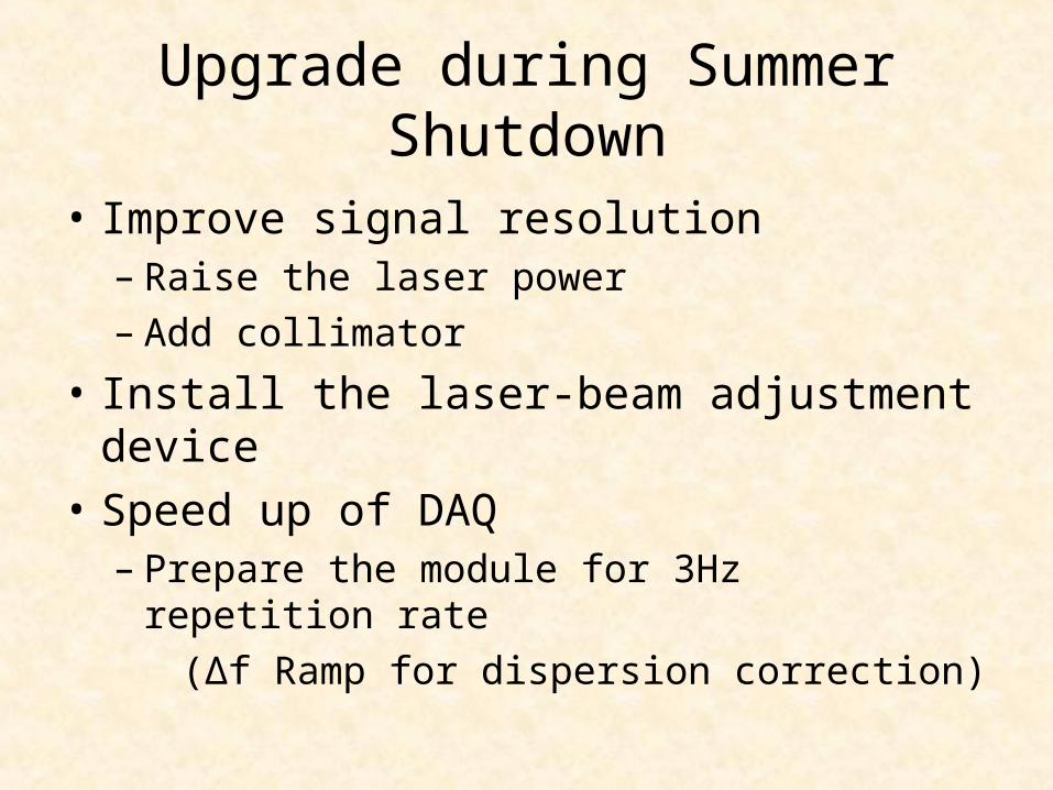
Upgrade during Summer Shutdown
• Improve signal resolution– Raise the laser power– Add collimator
• Install the laser-beam adjustment device• Speed up of DAQ
– Prepare the module for 3Hz repetition rate (Δf Ramp for dispersion correction)

Laser Upgrade
• To increase the Compton scattered photons from the laser-beam collision, replace with the stronger laser
• Laser specifications– Q-Switch Nd:YAG laser– wavelength : 532 nm ( 2nd harmonics )– pulse energy : 400 mJ @ 532 nm (GCR-3, SpectraPhysics) → 1500 mJ @ 532 nm (PRO-350, SpectraPhysics)– timing jitter : < 1.0 ns– pulse width : 8 ns @ 532 nm– linewidth : < 0.004 cm-1 @ 532 nm
new laser(PRO-350 Spectra-Physics)

Layout around Detector
DUMP
Cherenkov Detectorfor Wire Scanner
Front CollimatorLead, Φ20, 200 mm thickness
Movable Collimator in H & VLead, Φ10 or Φ15, 200 mm thickness
Rear CollimatorLead, Φ20, 200 mm thickness
CsI(Tl) Calorimetor
Cherenkov Detector(locally movable)
Movable Background Monitor (Plastic Scintillator with lead plate)
Movable Shutter50x50mm, 200 mm thickness lead block
Lead block shield
BDUMP
Wider chamber
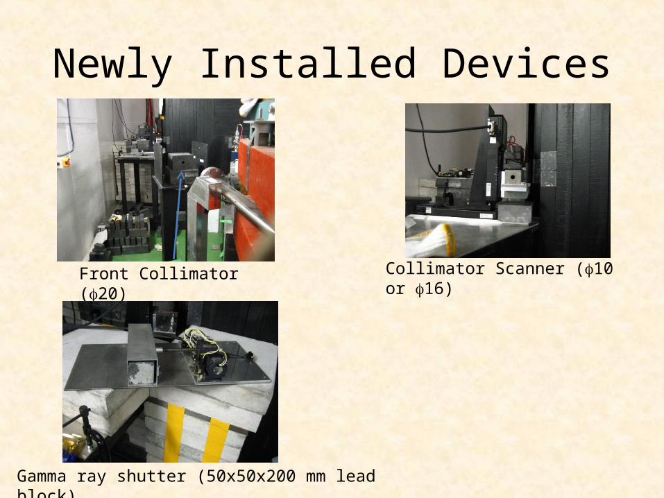
Newly Installed Devices
Collimator Scanner (10 or 16)Front Collimator (20)
Gamma ray shutter (50x50x200 mm lead block)

Laser Light Position Adjustment
• To adjust the laser position to the electron beam, screen monitor (using almina fluorescent material) is used.
• Since the previous screen monitor at the IP is temporal, reconstruction was needed to use the all the crossing mode.
beam image
laser light image
Image of screen monitor
beam image
laser light image
Horizontal:10 mm
Vertical:10 mm
CCD Camera
Screen Monitor
Laser Light
Electron Beam

Reconstruction of Screen Monitor
• Prepare two almina plates – changes according to the laser paths
• 10 um W wire is attached on the tips of the screen monitor holder– can measure bigger than 2-3 um vertical beam size at the IP
CCD Camera
CCD CameraLinear Insertion Stage
Electron Beam
Laser Light
CAD Design Screen Holder

Summary
• Horizontal beam size measurement using laserwire mode have been done by the end of May.
• During the summer shutdown, upgrade for the improvement of the signal resolution and the alignment method of the interferometer mode have been continued.
• Hardware upgrade has been almost finished.

Backup

Horizontal Beam Size Measurement
• User laserwire method to measure horizontal beam size – horizontal beam size at the ATF2
interaction point σx* > 2.8 μm
• Laser width at the IP is estimated to be around 10 um
Laser path

Interferometer Mode
174° 30°
8° 2°
Electron Beam
• With only one crossing angle, measurable range is small (7 % - 40 % of laser fringe pitch)
• By switching the crossing angle, measurable beam size range is widen.

Expected Beam Size Resolution
Parameters used in the simulation・ RMS of background photon amount: 10 % of signal photons・ RMS of electron beam position: 30 % of beam size・ Stability of laser fringe phase: 400 mrad・ Stability of laser power: 6.8 %・ One measurement time: 1 minute
Resolution of simulated beam size measurement

Laser Transport from EXT LW
Laser Transport Line (light brown plastic pipe)
Optical Table for Laser Transportand End of Transport Pipe