atlantis flo-tank underground modular · pdf fileatlantis flo-tanks™ consist of an...
TRANSCRIPT

GEOTECH SYSTEMS LTD - Box 6035 - TAURANGA 3146
Rev May 2012 Sales orders / enquiries - Email [email protected] - Phone 0800 436 832 - Fax 0800 422 466 Page 2 of 24
PRODUCT DESCRIPTION :
Atlantis Flo-Tanks™
are suited to all subsurface ex-filtration, retention and detention applications.
Atlantis Flo-Tanks™
consist of an assembly of lightweight structural components developed by Atlantis over 20 plus
years of on-going research and improvement.
Atlantis Flo-Tanks™
are manufactured using recycled polypropylene materials and are shipped as a ‘flat pack, ready
for on site assembly
FEATURES AND BENEFITS :
High void to solid ratio maximises the tanks in ground water storage capacity.
Flo-Tank’s™ high water storage capacity minimises the tanks footprint.
Range of Flo-Tank™ sizes and modules increases footprint and invert options.
Range of ‘cross plate’ options (3, 4 or 5 plate) accommodates a range of imposed compressive loads.
Being modular the final in-ground tank configuration can be designed and shaped as required.
Open internal structure ensures a high flow rate when configured as a pipe as well as a tank.
Manufactured from Eco friendly durable recycled polypropylene giving a long in ground life.
Supplied as a flat-pack to minimise transport and on-site storage costs
Simple peg and hole on site assembly ensures lower labour costs
Lightweight elements enable assembled tanks to be readily manhandled
ATLANTIS® FLO-TANK™ PHYSICAL DIMENSIONS
FLO-TANK NAME
TANK SIZE W X L X H
No. PLATES / TANK (4 CROSS PLATE MODULE)
GROSS TANK VOL.
WATER STORAGE VOL
No. TANKS / M3 WATER
TANK WEIGHT
TINY I x module
204 x 685 x 240mm
4 x side plus 4 x small cross
0.0335m3 0.0318m3 31.5 / m3
MINI I x module
408 x 685 x 240mm
2 x large plus 2 x side plus
4 x small cross 0.0671m3 0.059m3 16.9 / m3 3.97kg
SINGLE I x module
408 x 685 x 450mm
4 x large plus 4 x cross
0.126m3 0.119m3 8.40 / m3 6.34kg
DOUBLE 2 x modules
408 x 685 x 880mm
7 x large plus 8 x cross
0.246m3 0.233m3 4.29 / m3 11.79kg
TRIPLE 3 x modules
408 x 685 x 1310mm
10 x large plus 12 x cross
0.366m3 0.348m3 2.87 / m3 17.24kg
QUAD 4 x modules
408 x 685 x 1720mm
13 x large plus 16 x cross
0.486m3 0.462m3 2.16 /m3 22.68kg
PENTA 5 x modules
408 X 685 x 2170mm
16 x large plus 20 x cross
0.607m3 0.576m3 1.73 /m3 28.12kg
ATLANTIS® FLO-TANK
™ UNDERGROUND MODULAR TANKS
RETENTION : DETENTION : INFILTRATION
GEOTECH SYSTEMS LTD - Box 6035 - TAURANGA 3146
Rev May 2012 Sales orders / enquiries - Email [email protected] - Phone 0800 436 832 - Fax 0800 422 466 Page 3 of 24
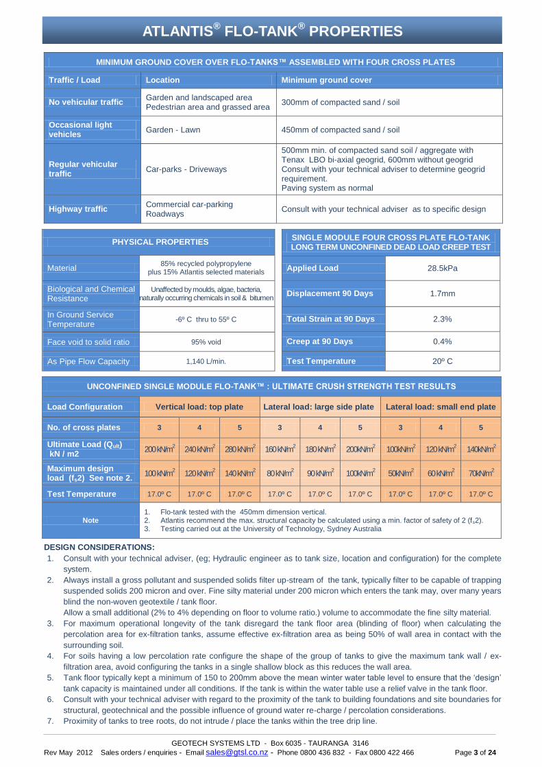
MINIMUM GROUND COVER OVER FLO-TANKS™ ASSEMBLED WITH FOUR CROSS PLATES
Traffic / Load Location Minimum ground cover
No vehicular traffic Garden and landscaped area Pedestrian area and grassed area
300mm of compacted sand / soil
Occasional light vehicles
Garden - Lawn 450mm of compacted sand / soil
Regular vehicular traffic
Car-parks - Driveways
500mm min. of compacted sand soil / aggregate with Tenax LBO bi-axial geogrid, 600mm without geogrid Consult with your technical adviser to determine geogrid requirement. Paving system as normal
Highway traffic Commercial car-parking Roadways
Consult with your technical adviser as to specific design
DESIGN CONSIDERATIONS:
1. Consult with your technical adviser, (eg; Hydraulic engineer as to tank size, location and configuration) for the complete
system.
2. Always install a gross pollutant and suspended solids filter up-stream of the tank, typically filter to be capable of trapping
suspended solids 200 micron and over. Fine silty material under 200 micron which enters the tank may, over many years
blind the non-woven geotextile / tank floor.
Allow a small additional (2% to 4% depending on floor to volume ratio.) volume to accommodate the fine silty material.
3. For maximum operational longevity of the tank disregard the tank floor area (blinding of floor) when calculating the
percolation area for ex-filtration tanks, assume effective ex-filtration area as being 50% of wall area in contact with the
surrounding soil.
4. For soils having a low percolation rate configure the shape of the group of tanks to give the maximum tank wall / ex-
filtration area, avoid configuring the tanks in a single shallow block as this reduces the wall area.
5. Tank floor typically kept a minimum of 150 to 200mm above the mean winter water table level to ensure that the ‘design’
tank capacity is maintained under all conditions. If the tank is within the water table use a relief valve in the tank floor.
6. Consult with your technical adviser with regard to the proximity of the tank to building foundations and site boundaries for
structural, geotechnical and the possible influence of ground water re-charge / percolation considerations.
7. Proximity of tanks to tree roots, do not intrude / place the tanks within the tree drip line.
PHYSICAL PROPERTIES
Material 85% recycled polypropylene
plus 15% Atlantis selected materials
Biological and Chemical Resistance
Unaffected by moulds, algae, bacteria, naturally occurring chemicals in soil & bitumen
In Ground Service Temperature
-6º C thru to 55º C
Face void to solid ratio 95% void
As Pipe Flow Capacity 1,140 L/min.
SINGLE MODULE FOUR CROSS PLATE FLO-TANK LONG TERM UNCONFINED DEAD LOAD CREEP TEST
Applied Load 28.5kPa
Displacement 90 Days 1.7mm
Total Strain at 90 Days 2.3%
Creep at 90 Days 0.4%
Test Temperature 20º C
UNCONFINED SINGLE MODULE FLO-TANK™ : ULTIMATE CRUSH STRENGTH TEST RESULTS
Load Configuration Vertical load: top plate Lateral load: large side plate Lateral load: small end plate
No. of cross plates 3 4 5 3 4 5 3 4 5
Ultimate Load (Qult) kN / m2
200 kN/m2
240 kN/m2
280 kN/m2
160 kN/m2 180 kN/m
2 200kN/m
2 100kN/m
2 120 kN/m
2 140kN/m
2
Maximum design load (fs2) See note 2.
100 kN/m2
120 kN/m2
140 kN/m2
80 kN/m2 90 kN/m
2 100kN/m
2 50kN/m
2 60 kN/m
2 70kN/m
2
Test Temperature 17.0º C 17.0º C 17.0º C 17.0º C 17.0º C 17.0º C 17.0º C 17.0º C 17.0º C
Note 1. Flo-tank tested with the 450mm dimension vertical. 2. Atlantis recommend the max. structural capacity be calculated using a min. factor of safety of 2 (fs2). 3. Testing carried out at the University of Technology, Sydney Australia
ATLANTIS® FLO-TANK
® PROPERTIES

GEOTECH SYSTEMS LTD - Box 6035 - TAURANGA 3146
Rev May 2012 Sales orders / enquiries - Email [email protected] - Phone 0800 436 832 - Fax 0800 422 466 Page 4 of 24
ATLANTIS® FLO-TANK
® CONFIGURATION OPTIONS
GEOTECH SYSTEMS LTD - Box 6035 - TAURANGA 3146
Rev May 2012 Sales orders / enquiries - Email [email protected] - Phone 0800 436 832 - Fax 0800 422 466 Page 5 of 24
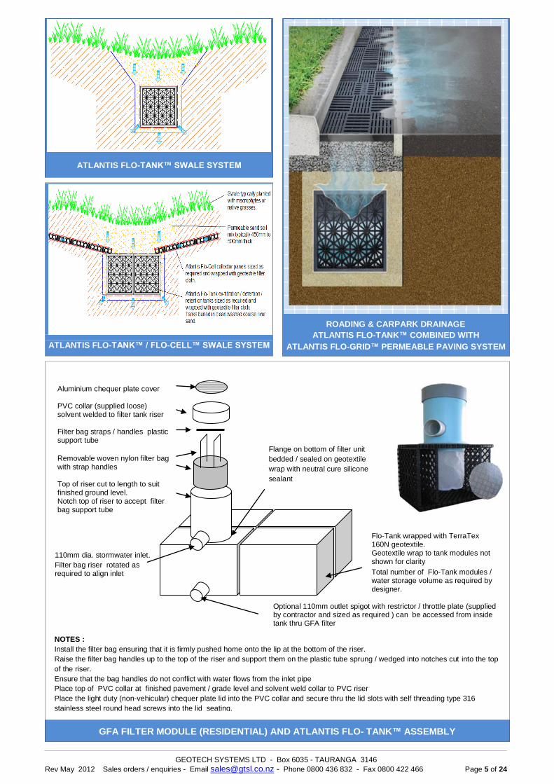
Optional 110mm outlet spigot with restrictor / throttle plate (supplied by contractor and sized as required ) can be accessed from inside tank thru GFA filter
Total number of Flo-Tank modules / water storage volume as required by designer.
NOTES :
Install the filter bag ensuring that it is firmly pushed home onto the lip at the bottom of the riser.
Raise the filter bag handles up to the top of the riser and support them on the plastic tube sprung / wedged into notches cut into the top
of the riser.
Ensure that the bag handles do not conflict with water flows from the inlet pipe
Place top of PVC collar at finished pavement / grade level and solvent weld collar to PVC riser
Place the light duty (non-vehicular) chequer plate lid into the PVC collar and secure thru the lid slots with self threading type 316
stainless steel round head screws into the lid seating.
GFA FILTER MODULE (RESIDENTIAL) AND ATLANTIS FLO- TANK™ ASSEMBLY
110mm dia. stormwater inlet.
Filter bag riser rotated as required to align inlet
Aluminium chequer plate cover PVC collar (supplied loose) solvent welded to filter tank riser Filter bag straps / handles plastic support tube
Removable woven nylon filter bag with strap handles Top of riser cut to length to suit finished ground level. Notch top of riser to accept filter bag support tube
Flange on bottom of filter unit
bedded / sealed on geotextile
wrap with neutral cure silicone
sealant
ATLANTIS FLO-TANK™ SWALE SYSTEM
ROADING & CARPARK DRAINAGE
ATLANTIS FLO-TANK™ COMBINED WITH
ATLANTIS FLO-GRID™ PERMEABLE PAVING SYSTEM
ATLANTIS FLO-TANK™ / FLO-CELL™ SWALE SYSTEM
Flo-Tank wrapped with TerraTex 160N geotextile. Geotextile wrap to tank modules not shown for clarity
GEOTECH SYSTEMS LTD - Box 6035 - TAURANGA 3146
Rev May 2012 Sales orders / enquiries - Email [email protected] - Phone 0800 436 832 - Fax 0800 422 466 Page 6 of 24
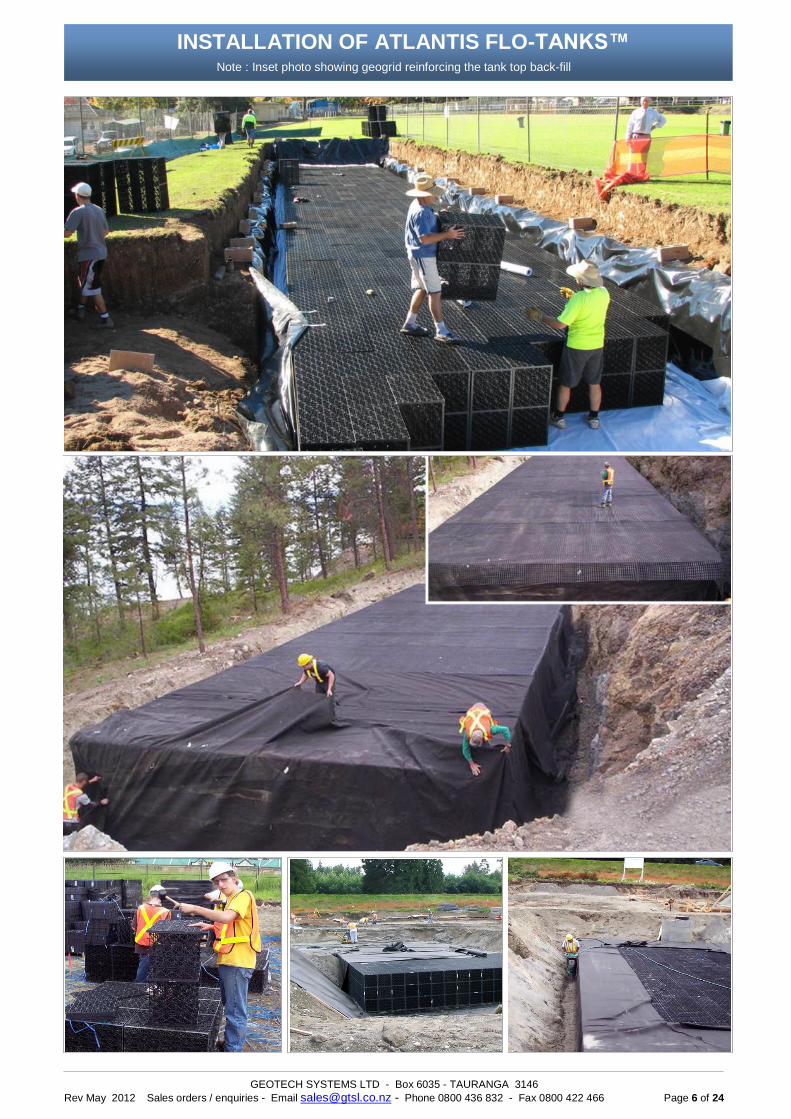
INSTALLATION OF ATLANTIS FLO-TANKS™
Note : Inset photo showing geogrid reinforcing the tank top back-fill
GEOTECH SYSTEMS LTD - Box 6035 - TAURANGA 3146
Rev May 2012 Sales orders / enquiries - Email [email protected] - Phone 0800 436 832 - Fax 0800 422 466 Page 7 of 24
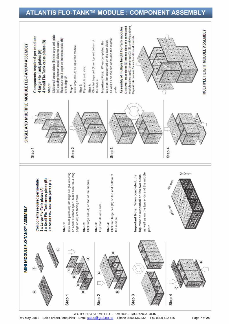
ATLANTIS FLO-TANK™ MODULE : COMPONENT ASSEMBLY
GEOTECH SYSTEMS LTD - Box 6035 - TAURANGA 3146
Rev May 2012 Sales orders / enquiries - Email [email protected] - Phone 0800 436 832 - Fax 0800 422 466 Page 8 of 24
Assembly time of units approx. as follows
Tank Size Time
Tiny 2 minutes
Mini 2 minutes
Single 2 minutes
Double 4 minutes
Triple 8 minutes
Quad 10 minutes
Pent 13 minutes
Assemble tanks as specified / documented
Completed tank modules should be staged as close to the installation area as possible to minimize handling. Strength determined by No. of cross plates. Ie;3, 4 or 5 cross plates. Evenly distribute and connect the cross plates over a large plate. To build a multiple height tank build on top of an existing completed single tank module to the required height. Cut holes thru horizontal plates as required for vertical inspection and maintenance ports before assembling multiple height units. Cut holes with a reciprocating saw, all holes cut between the vertical internal cross plates. See page 8 detailing the Flo-Tank™ assembly sequence.
NOTE
1. Atlantis® Matrix® tank modules must be installed with the 450mm side in the vertical dimension to ensure maximum strength.
2. For multiple height tanks the 3 pin edge of the cross plate must face up.
Installation of Atlantis® Flo-Tanks™
Step 1 – Excavation
Excavation size to allow for the tanks dimensions, backfill material encompassing the tank and compaction equipment access at the tank side walls. Size of bulk excavation to be as documented or use the following minimum dimensions;
Tank base allow 100mm to 1 50mm Tank side walls allow perimeter 300mm to 500mm Tank top cover depth typically 300mm 600mm plus paving system as specified. Excavate floor to an even level plane to the reduced level specified.
Step 2: Prepare Base
Place the specified base material to the specified thickness, evenly spread to the correct line and level. Typically base material is a coarse washed river sand or a free draining open graded 20mm aggregate. If the tank is not expected to ex-filtrate water to the surrounding soils then a GAP 20 type material is acceptable. Base material compacted to 95%.
Step 3: Placing of the impermeable plastic liner.
If required install specified liner. Drape the plastic liner across the floor and up walls. Take care not to tear or puncture the liner At aggregate or GAP20 base material use TerraTex non-woven geotextile cushion layer under the liner. All overlapping edges / joins to be heat welded by an experienced poly-plastic welder.
Use only large liner sheets to minimize the number of welded joins. Avoid site welded vertical joints if possible. Ensure liner at the ends and sides is sufficient to wrap up and over the tank.
Step 4: Place Geotextile Wrap to Tanks
Typically for most applications TerraTex 160N non-woven needle-punched geotextile is used. Lay the Geotextile into the excavation, over lapping edges by 300mm or as specified. Ensure geotextile at the ends and sides is sufficient to wrap up and over the tank. Secure / tape the geotextile against sliding or blowing down into the excavation.
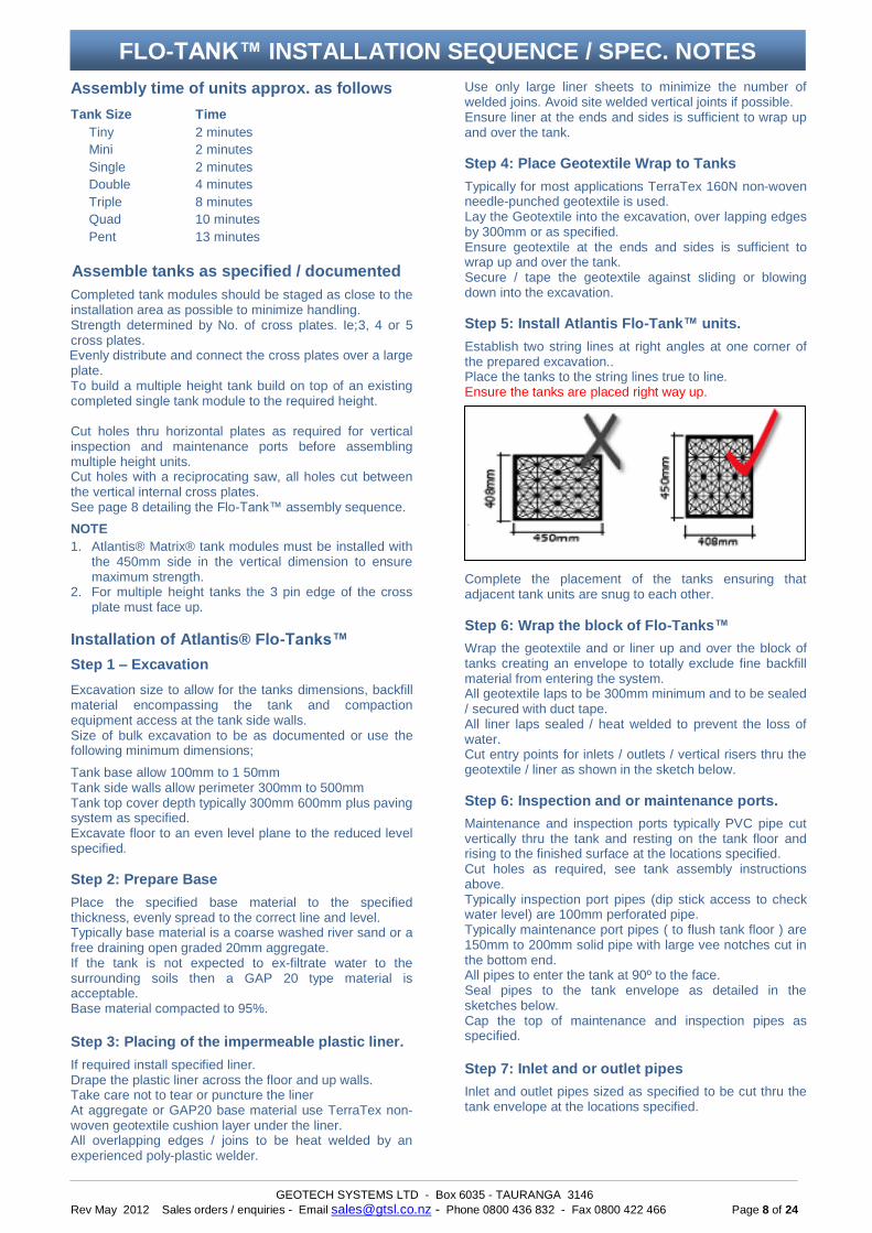
Step 5: Install Atlantis Flo-Tank™ units.
Establish two string lines at right angles at one corner of the prepared excavation.. Place the tanks to the string lines true to line. Ensure the tanks are placed right way up.
Complete the placement of the tanks ensuring that adjacent tank units are snug to each other.
Step 6: Wrap the block of Flo-Tanks™
Wrap the geotextile and or liner up and over the block of tanks creating an envelope to totally exclude fine backfill material from entering the system. All geotextile laps to be 300mm minimum and to be sealed / secured with duct tape. All liner laps sealed / heat welded to prevent the loss of water. Cut entry points for inlets / outlets / vertical risers thru the geotextile / liner as shown in the sketch below.
Step 6: Inspection and or maintenance ports.
Maintenance and inspection ports typically PVC pipe cut vertically thru the tank and resting on the tank floor and rising to the finished surface at the locations specified. Cut holes as required, see tank assembly instructions above. Typically inspection port pipes (dip stick access to check water level) are 100mm perforated pipe. Typically maintenance port pipes ( to flush tank floor ) are 150mm to 200mm solid pipe with large vee notches cut in the bottom end. All pipes to enter the tank at 90º to the face. Seal pipes to the tank envelope as detailed in the sketches below. Cap the top of maintenance and inspection pipes as specified.
Step 7: Inlet and or outlet pipes
Inlet and outlet pipes sized as specified to be cut thru the tank envelope at the locations specified.
FLO-TANK™ INSTALLATION SEQUENCE / SPEC. NOTES

GEOTECH SYSTEMS LTD - Box 6035 - TAURANGA 3146
Rev May 2012 Sales orders / enquiries - Email [email protected] - Phone 0800 436 832 - Fax 0800 422 466 Page 9 of 24
Pipes 450mm dia. and larger with the approval of the system designer need only abut the tank and not penetrate the face. Caution: The filter system to be capable of trapping all floatables, eg plastic bags. All pipes to enter the tank at 90º to the face. Seal pipes to the tank envelope as detailed in the sketches below. Step 8: Placing backfill to sides of tank.
Backfill the tank sides in lifts of 200mm. Backfill to be evenly placed side to side to minimize displacement of the tank (shoving). With smaller tank units / configurations place fill material on top of the tank to ‘weight it’ to help minimizing shoving. Compact to 95% using a hand-held powered compactor, a vibrating type compactor will assist in eliminating minor gaps between adjacent tank units.
Step 9: Placing backfill to top of tank.
Exercise care when placing the first 200mm lift of backfill on to the top of the tanks.
Place first lift of backfill with an excavator reaching out and over the tank. For subsequent lifts it is acceptable to use a small tracked or wheeled machine with a low ground pressure. Do not drive directly on the exposed tank surface. Generally overfill final lift, compact then blade down to required level. Compact each lift to 95% using vibrating plate / roller compactor of appropriate size. Backfill material and profile as specified. Step 10: Optional geogrid
At load bearing applications such as car-parking areas where there is reduced cover over the tanks install geogrid as specified by project designer. Typically Tenax bi-axial LBO330 geogrid is used. Geogrid laps to be 500mm minimum and to extend a 500mm beyond the excavation footprint.
IMPORTANT ALL water entering the Atlantis system must be filtered by an appropriate device including during the
the construction phase of the tank system, use appropriate sediment / silt control systems
PIPE TO TANK CONNECTION DETAILS