· pdf fileatm security specification, version 1.1 af-sec-0100.002 page iii atm technical...
TRANSCRIPT

Technical Committee
ATM Security SpecificationVersion 1.1
af-sec-0100.002
March, 2001

ATM Security Specification, Version 1.1 af-sec-0100.002
Page ii ATM Technical Committee
© 2001 by The ATM Forum. This specification/document may be reproduced and distributed in whole,but (except as provided in the next sentence) not in part, for internal and informational use only and notfor commercial distribution. Notwithstanding the foregoing sentence, any protocol implementationconformance statements (PICS) or implementation conformance statements (ICS) contained in thisspecification/document may be separately reproduced and distributed provided that it is reproduced anddistributed in whole, but not in part, for uses other than commercial distribution. All other rightsreserved. Except as expressly stated in this notice, no part of this specification/document may bereproduced or transmitted in any form or by any means, or stored in any information storage and retrievalsystem, without the prior written permission of The ATM Forum.
The information in this publication is believed to be accurate as of its publication date. Such informationis subject to change without notice and The ATM Forum is not responsible for any errors. The ATMForum does not assume any responsibility to update or correct any information in this publication.Notwithstanding anything to the contrary, neither The ATM Forum nor the publisher make anyrepresentation or warranty, expressed or implied, concerning the completeness, accuracy, or applicabilityof any information contained in this publication. No liability of any kind shall be assumed by The ATMForum or the publisher as a result of reliance upon any information contained in this publication.
The receipt or any use of this document or its contents does not in any way create by implication orotherwise:• Any express or implied license or right to or under any ATM Forum member company's patent,
copyright, trademark or trade secret rights which are or may be associated with the ideas, techniques,concepts or expressions contained herein; nor
• Any warranty or representation that any ATM Forum member companies will announce anyproduct(s) and/or service(s) related thereto, or if such announcements are made, that such announcedproduct(s) and/or service(s) embody any or all of the ideas, technologies, or concepts containedherein; nor
• Any form of relationship between any ATM Forum member companies and the recipient or user ofthis document.
Implementation or use of specific ATM standards or recommendations and ATM Forum specificationswill be voluntary, and no company shall agree or be obliged to implement them by virtue of participationin The ATM Forum.
The ATM Forum is a non-profit international organization accelerating industry cooperation on ATMtechnology. The ATM Forum does not, expressly or otherwise, endorse or promote any specific productsor services.
NOTE: The user's attention is called to the possibility that implementation of the ATM interoperabilityspecification contained herein may require use of an invention covered by patent rights held by ATMForum Member companies or others. By publication of this ATM interoperability specification, noposition is taken by The ATM Forum with respect to validity of any patent claims or of any patent rightsrelated thereto or the ability to obtain the license to use such rights. ATM Forum Member companiesagree to grant licenses under the relevant patents they own on reasonable and nondiscriminatory termsand conditions to applicants desiring to obtain such a license. For additional information contact:
The ATM ForumWorldwide Headquarters1000 Executive Parkway #220St. Louis, MO 63141Tel: +1 314 205 0200Fax: +1 314 576 7989

ATM Security Specification, Version 1.1 af-sec-0100.002
Page iii ATM Technical Committee
Acknowledgments
The production of this specification would not be possible without the enormous amount of effort providedby many individuals. Special acknowledgements for their hard work and dedication go to RichardGraveman and Wolfgang Klasen, the chair and vice-chair of the Security Working Group.
In addition, the following individuals (listed alphabetically), among others, contributed their time andexpertise to the development of this specification:
Asher AltmanCarter BullardDon ChoiLouis FinkelsteinKim HebdaAlexander JurisicChris KubicScott LaneMaryline LaurentRandy MitchellHikaru MoritaMohammad PeyravianMichael PierceLyndon PiersonBrian RosenDan SchnackenbergLinda ShieldsHorace Thompson
Thomas TarmanEditor, ATM Forum Security Working Group

ATM Security Specification, Version 1.1 af-sec-0100.002
Page iv ATM Technical Committee
Foreword
This document corrects errata, clarifies procedures, and contains editorial corrections to the ATMSecurity Specification Version 1.0. Due to the errata corrections and procedural clarifications, thisspecification is not directly interoperable with the Version 1.0 specification.
The following table describes the substantive revisions from the Version 1.0 specification:
Section Modification
General Restructured document
General DES-40 algorithm is deprecated
1.2 Updated normative and informative references
5.1 Removed references to CRL transport in Security Message Exchange
5.1.3.2.3 Created new codepoint for Version 1.1
5.1.3.2.7.2 Clarified procedures for non-explicit security agent addressing
5.1.3.2.8 Clarified procedures for relative ID security agent addressing and assignment ofSecurity Association IDs
5.1.3.2.10 Clarified procedures for using the security service data section
5.1.4.4.2 Clarified procedure for assignment of Version numbers in Security AssociationSections
5.1.4.5, 5.1.4.6 Clarified procedures for endpoint request for security services and acknowledgements
5.1.5.3.5 Changed timer and counter values from “recommended” values to specified values
5.1.5.3.6, 5.1.6 Renamed cause code from “security services failure” to “call rejected” to align withsignaling addenda. The assigned cause code value was inserted, and the cause codeindication of “security exception” was noted for this value.
5.3.1.2 Clarified Session Key Changeover procedure, and added text describing SKC usagewith the integrity service.
6.5 Added Specification and Description Language (SDL) diagrams for in-band finitestate machines
7.1 Changed codepoints to correct Version 1.0 errors
7.2 Clarified procedures for using the security service specification section (securityservice declaration and security service options)
7.2.1 Clarified coding of the Security Service Declaration for use in peer to peer and endsystem to proxy scenarios
7.2.2.2 Added codepoint for data integrity service options (Required, with or withoutReplay/Reordering Protection)
7.2.2.7 Added certificate exchange service options
7.2.3 Added support for user-defined algorithm details
7.2.3 Clarified procedures for inserting octet groups in the Security Service AlgorithmSection and using the Organizationally Unique Identifier (OUI)
7.2.3.7, 7.2.3.8,7.2.3.9
Clarified coding of algorithm details octets for profile groups
7.2.3.9 Changed codepoint for the hash algorithm details identifier to its correct value
7.3.1 Clarified the contents of the fields in the Confidential Parameters octet group
7.4 Clarified placement of the SAS Digital Signature within the Authentication Section
7.4.5 Clarified the contents of the ConfPar portion digital signature buffer

ATM Security Specification, Version 1.1 af-sec-0100.002
Page v ATM Technical Committee
7.4.6 Clarified the method for calculating the SAS Digital Signature
8.7 Removed the use of point compression for elliptic curve cryptosystems, removesample curves, and changed recommended field sizes
8.7.6 Added and updated references for elliptic curves
Appendix I Clarified informative procedure for calculating resynchronization rate
Appendix III Updated and corrected example SSIE encodings
Appendix IV Created new informative section on security message coding principles and identifiervalues

ATM Security Specification, Version 1.1 af-sec-0100.002
Page vi ATM Technical Committee
Contents
1 INTRODUCTION........................................................................................................................... 11.1 GOALS....................................................................................................................................... 11.2 REFERENCES .............................................................................................................................. 2
1.2.1 Normative References........................................................................................................ 2
1.2.2 Informative References...................................................................................................... 3
1.3 DEFINITIONS .............................................................................................................................. 41.4 ABBREVIATIONS......................................................................................................................... 51.5 SPECIFICATION SCOPE ................................................................................................................ 6
1.5.1 User Plane Security Services ............................................................................................. 71.5.1.1 Authentication..............................................................................................................................71.5.1.2 Confidentiality..............................................................................................................................71.5.1.3 Integrity........................................................................................................................................71.5.1.4 Access Control .............................................................................................................................8
1.5.2 Control Plane Security Services ........................................................................................ 81.5.2.1 Authentication and Integrity..........................................................................................................8
1.5.3 Support Services................................................................................................................ 91.5.3.1 Security Message Exchange and Negotiation.................................................................................91.5.3.2 Key Exchange...............................................................................................................................91.5.3.3 Session Key Update......................................................................................................................91.5.3.4 Certification Infrastructure..........................................................................................................10
1.6 COMPLIANCE ........................................................................................................................... 101.6.1 Security Algorithm Profiles ............................................................................................. 11
1.6.2 Security Message Exchange Profiles ............................................................................... 13
2 TOP-LEVEL REFERENCE MODELS....................................................................................... 152.1 SECURITY ASSOCIATIONS AND ATM INTERFACES...................................................................... 152.2 MULTIPLE SECURITY ASSOCIATIONS AND NESTING.................................................................... 172.3 SECURITY INFORMATION EXCHANGE......................................................................................... 19
3 SECURITY SERVICES FOR THE USER PLANE .................................................................... 233.1 ENTITY AUTHENTICATION........................................................................................................ 23
3.1.1 Authentication Reference Model...................................................................................... 23
3.1.2 Authentication Infrastructure and Mechanisms................................................................ 25
3.1.3 Authentication Algorithms ............................................................................................... 263.1.3.1 Asymmetric Digital Signature Algorithms...................................................................................263.1.3.2 Symmetric Digital Signature Algorithms (MACs) .......................................................................263.1.3.3 Hash Functions...........................................................................................................................27
3.1.4 Error Processing ............................................................................................................. 27
3.2 CONFIDENTIALITY.................................................................................................................... 273.2.1 Confidentiality Reference Model ..................................................................................... 27
3.2.2 Confidentiality Infrastructure and Mechanisms ............................................................... 29
3.2.3 Bypass of Special Network Cells...................................................................................... 30
3.3 DATA ORIGIN AUTHENTICATION AND INTEGRITY ...................................................................... 313.3.1 Integrity Reference Model ............................................................................................... 31
3.3.2 Integrity Infrastructure and Mechanisms ......................................................................... 33

ATM Security Specification, Version 1.1 af-sec-0100.002
Page vii ATM Technical Committee
3.3.2.1 Message Authentication Code.....................................................................................................35
3.4 ACCESS CONTROL.................................................................................................................... 363.4.1 Access Control Reference Model ..................................................................................... 36
3.4.2 Access Control Infrastructure and Mechanisms ............................................................... 37
3.4.3 Error Processing ............................................................................................................. 37
4 SECURITY SERVICES FOR THE CONTROL PLANE ........................................................... 384.1 CONTROL PLANE DATA ORIGIN AUTHENTICATION AND DATA INTEGRITY................................... 38
4.1.1 Error Conditions ............................................................................................................. 39
5 SUPPORT SERVICES ................................................................................................................. 405.1 SECURITY INFORMATION EXCHANGE......................................................................................... 41
5.1.1 Security Message Exchange and Negotiation Protocols................................................... 415.1.1.1 Three-Way Security Message Exchange Protocol ........................................................................445.1.1.2 Two-Way Security Message Exchange Protocol ..........................................................................45
5.1.2 Label Transport............................................................................................................... 47
5.1.3 Security Services Information Element ............................................................................ 475.1.3.1 Security Services Information Element Format............................................................................475.1.3.2 Security Association Section.......................................................................................................48
5.1.3.2.1 Security Association Section Type ........................................................................................485.1.3.2.2 Security Association Section Length .....................................................................................495.1.3.2.3 Version ................................................................................................................................495.1.3.2.4 Transport Indicator...............................................................................................................495.1.3.2.5 Flow Indicator ......................................................................................................................505.1.3.2.6 Security Association Section Discard Indicator .....................................................................515.1.3.2.7 Scope ...................................................................................................................................51
5.1.3.2.7.1 Explicit Security Agent Specification ............................................................................525.1.3.2.7.2 Non-Explicit Security Agent Specification.....................................................................53
5.1.3.2.7.2.1 Region...................................................................................................................535.1.3.2.7.2.2 Role ......................................................................................................................54
5.1.3.2.7.3 Relative ID Security Peer Specification .........................................................................555.1.3.2.8 Relative Identifier ................................................................................................................555.1.3.2.9 Target Security Agent Identifier............................................................................................575.1.3.2.10 Security Service Data Section.............................................................................................57
5.1.3.2.10.1 Security Message Exchange Data Section....................................................................575.1.3.2.10.2 Label Based Access Control Section ...........................................................................58
5.1.4 Message Exchange within Signaling ................................................................................ 585.1.4.1 Point-to-Point Connections .........................................................................................................595.1.4.2 Point-to-Multipoint Connections .................................................................................................595.1.4.3 Leaf Initiated Join Capability......................................................................................................60
5.1.4.3.1 Root Prompted Join ..............................................................................................................615.1.4.3.2 Leaf Prompted Join without Root Notification ......................................................................61
5.1.4.4 Security Agent Procedures for Signaling-Based Message Exchange.............................................615.1.4.4.1 General Procedures ..............................................................................................................615.1.4.4.2 Initiating Security Agent Procedures.....................................................................................62
5.1.4.4.2.1 Call/Connection Request...............................................................................................625.1.4.4.2.2 Call/Connection Acceptance..........................................................................................62
5.1.4.4.3 Responding Security Agent Procedures.................................................................................635.1.4.4.3.1 Call/Connection Request...............................................................................................635.1.4.4.3.2 Call/Connection Acceptance..........................................................................................64
5.1.4.5 Endpoint Requests for Security Services .....................................................................................64

ATM Security Specification, Version 1.1 af-sec-0100.002
Page viii ATM Technical Committee
5.1.4.6 Acknowledgements to Endpoints Requesting Security Services ...................................................65
5.1.5 Message Exchange within the User Plane........................................................................ 655.1.5.1 Security Message Exchange for Signaled Point-to-Point Connections ..........................................65
5.1.5.1.1 Details of Security Call Establishment..................................................................................675.1.5.1.1.1 Establish Point-to-Point on Calling Side........................................................................675.1.5.1.1.2 Establish Point to Point on Called Side .........................................................................68
5.1.5.2 Security Message Exchange for Permanent Point-to-Point Connections .......................................685.1.5.2.1 Details of Secure Call Provisioning for PVCs .......................................................................70
5.1.5.2.1.1 Establish Point-to-Point on Initiator Side.......................................................................705.1.5.2.1.2 Establish Point-to-Point on Responder Side...................................................................70
5.1.5.3 In-Band Security Message Exchange Protocol .............................................................................715.1.5.3.1 Protocol Procedures..............................................................................................................715.1.5.3.2 General Message Format and Message Field Coding ............................................................73
5.1.5.3.2.1 Message Type...............................................................................................................745.1.5.3.2.2 Message Length............................................................................................................745.1.5.3.2.3 Variable Length Information Elements ..........................................................................75
5.1.5.3.2.3.1 Security Services Information Element...................................................................755.1.5.3.2.3.2 Cause Information Element....................................................................................75
5.1.5.3.3 Message Contents for In-Band SME Messages .....................................................................755.1.5.3.3.1 Flow 1-3WE .................................................................................................................755.1.5.3.3.2 Flow2-3WE ..................................................................................................................755.1.5.3.3.3 FLOW3-3WE ...............................................................................................................755.1.5.3.3.4 CONFIRM-AP..............................................................................................................765.1.5.3.3.5 Fault .............................................................................................................................76
5.1.5.3.4 Timer Definitions.................................................................................................................765.1.5.3.5 Timer Values .......................................................................................................................775.1.5.3.6 Protocol Error Handling .......................................................................................................77
5.1.6 Security Information Exchange Error Processing ............................................................ 78
5.1.7 Security OAM Cells......................................................................................................... 795.1.7.1 Overview of ATM Layer OAM Cell Flows .................................................................................79
5.1.7.1.1 F4 Flow of OAM Cells.........................................................................................................80
5.1.7.1.2 F5 Flow of OAM Cells.........................................................................................................815.1.7.2 Security OAM Cell Formats .......................................................................................................82
5.1.7.2.1 Non-Real-Time Security OAM Cell Formats ........................................................................835.1.7.2.1.1 Data Confidentiality SKE OAM Cell Format.................................................................835.1.7.2.1.2 Data Integrity SKE OAM Cell Format...........................................................................84
5.1.7.2.2 Real Time Security OAM Cell Formats ................................................................................845.1.7.2.2.1 Data Confidentiality SKC OAM Cell Format ................................................................845.1.7.2.2.2 Data Integrity SKC OAM Cell Format ..........................................................................85
5.1.7.3 Use of the Security OAM Cell Relative ID Field.........................................................................855.1.7.3.1 Initiation of Security OAM Cells ..........................................................................................865.1.7.3.2 Processing for Security OAM Cells Received on the Plaintext Interface ................................875.1.7.3.3 Processing for Security OAM Cells Received on the Ciphertext Interface..............................87
5.2 KEY EXCHANGE....................................................................................................................... 875.2.1 Key Exchange Infrastructure and Mechanisms ................................................................ 87
5.2.2 Key Exchange Algorithms................................................................................................ 875.2.2.1 Asymmetric Algorithms for Key Exchange..................................................................................885.2.2.2 Symmetric Algorithms for Key Exchange....................................................................................88
5.2.3 Generation of Master Keys .............................................................................................. 885.2.3.1 Master Keys on Point-To-Point Connections ...............................................................................88

ATM Security Specification, Version 1.1 af-sec-0100.002
Page ix ATM Technical Committee
5.2.3.2 Master Keys on Point-To-Multipoint Connections.......................................................................89
5.2.4 Generation of Initial Session Keys................................................................................... 89
5.2.5 Error Processing ............................................................................................................. 89
5.3 SESSION KEY UPDATE .............................................................................................................. 905.3.1 Session Key Update Protocol........................................................................................... 90
5.3.1.1 Session Key Exchange (SKE) Process.........................................................................................905.3.1.1.1 SKE Processing at the Source (or Key Update Initiator)........................................................905.3.1.1.2 SKE Processing at the Destination (or Key Update Responder).............................................91
5.3.1.2 Session Key Changeover (SKC) Process .....................................................................................925.3.1.2.1 SKC Processing at the Source (or Key Update Initiator)........................................................925.3.1.2.2 SKC Processing at the Destination (or Key Update Responder) ............................................93
5.3.1.3 Session Key Exchange Algorithms..............................................................................................93
5.4 CERTIFICATES.......................................................................................................................... 94
6 IN-BAND SECURITY MESSAGE EXCHANGE FINITE STATE MACHINE (FSM)............. 956.1 MESSAGE SEQUENCE CHART..................................................................................................... 956.2 FSM STATES ........................................................................................................................... 966.3 FSM EVENTS........................................................................................................................... 966.4 TIMERS AND CONSTANTS.......................................................................................................... 976.5 SDL ........................................................................................................................................ 97
7 SECURITY SERVICE DATA STRUCTURES ..........................................................................1007.1 SECURITY AGENT IDENTIFIERS ................................................................................................100
7.1.1 Initiator Distinguished Name..........................................................................................100
7.1.2 Responder Distinguished Name ......................................................................................101
7.1.3 Security Agent Distinguished Name................................................................................102
7.2 SECURITY SERVICE SPECIFICATION SECTION ............................................................................1037.2.1 Security Service Declaration ..........................................................................................104
7.2.2 Security Service Options Section ....................................................................................1057.2.2.1 Data Confidentiality Service Options ........................................................................................1057.2.2.2 Data Integrity Service Options ..................................................................................................1057.2.2.3 Authentication Service Options.................................................................................................1067.2.2.4 Key Exchange Service Options .................................................................................................1067.2.2.5 Session Key Update Service Options ........................................................................................1067.2.2.6 Access Control Service Options ................................................................................................1077.2.2.7 Certificate Exchange Service Options .......................................................................................107
7.2.3 Security Service Algorithm Description Section..............................................................1097.2.3.1 Data Confidentiality Algorithm.................................................................................................1097.2.3.2 Data Integrity Algorithm...........................................................................................................1117.2.3.3 Hash Algorithm........................................................................................................................1137.2.3.4 Signature Algorithm .................................................................................................................1147.2.3.5 Key Exchange Algorithm..........................................................................................................1157.2.3.6 Session Key Update Algorithm .................................................................................................1207.2.3.7 Authentication Algorithm Profile Group ...................................................................................1217.2.3.8 Integrity Algorithm Profile Group .............................................................................................1237.2.3.9 Confidentiality Algorithm Profile Group ...................................................................................126
7.3 CONFIDENTIAL PARAMETERS SECTION .....................................................................................1317.3.1 Confidential Parameters.................................................................................................132
7.3.2 Master Key.....................................................................................................................133
7.3.3 First Data Confidentiality Session Key ...........................................................................133

ATM Security Specification, Version 1.1 af-sec-0100.002
Page x ATM Technical Committee
7.3.4 First Data Integrity Session Key .....................................................................................134
7.4 AUTHENTICATION SECTION .....................................................................................................1347.4.1 Initiator Random Number (Nonce)..................................................................................135
7.4.2 Responder Random Number (Nonce) ..............................................................................136
7.4.3 Time-Variant Time Stamp ...............................................................................................136
7.4.4 Credentials.....................................................................................................................137
7.4.5 Security Message Exchange Digital Signature................................................................1387.4.5.1 Digital Signature Calculation–Two-Way Exchange Protocol......................................................140
7.4.5.1.1 FLOW1-2WE.....................................................................................................................1407.4.5.1.2 FLOW2-2WE.....................................................................................................................140
7.4.5.2 Digital Signature Buffer–Three-Way Exchange Protocol ...........................................................1417.4.5.2.1 FLOW2-3WE.....................................................................................................................1417.4.5.2.2 FLOW3-3WE.....................................................................................................................142
7.4.6 SAS Digital Signature.....................................................................................................143
8 CRYPTOGRAPHIC PROCEDURES.........................................................................................1458.1 SYMMETRIC ENCRYPTION BIT ORDERING.................................................................................145
8.1.1 Bit Ordering for Data.....................................................................................................1458.1.1.1 The Effect of the Mode of Operation.........................................................................................145
8.1.2 Bit Ordering for Keys .....................................................................................................146
8.2 THE COUNTER MODE OF OPERATION .......................................................................................1468.2.1 Purpose ..........................................................................................................................146
8.2.2 Description.....................................................................................................................146
8.2.3 Properties.......................................................................................................................147
8.2.4 Cryptographic Synchronization ......................................................................................1478.2.4.1 SKC OAM Cell ........................................................................................................................1488.2.4.2 Encryptor Processing of SKC OAM Cells .................................................................................1488.2.4.3 Decryptor Processing of SKC OAM Cells .................................................................................148
8.2.5 Cell Loss Insensitivity.....................................................................................................1488.2.5.1 AAL1 and AAL3/4 Connections................................................................................................1488.2.5.2 AAL5 Connections ...................................................................................................................149
8.2.6 State Vector (SV) Definition............................................................................................1498.2.6.1 Galois Linear Feedback Shift Register (LFSR)..........................................................................149
8.2.6.1.1 LFSR Format in SV............................................................................................................1508.2.6.1.2 LFSR Processing................................................................................................................150
8.2.6.2 Initiator/Responder bit ..............................................................................................................1518.2.6.3 Sequence number .....................................................................................................................1518.2.6.4 Segment number.......................................................................................................................1528.2.6.5 Jump Number...........................................................................................................................152
8.2.7 Using the Counter Mode with Triple DES.......................................................................153
8.3 ASYMMETRIC AUTHENTICATION USING ESIGN........................................................................1538.3.1 Basic Procedure .............................................................................................................153
8.3.2 Precomputation Procedure .............................................................................................154
8.3.3 Example .........................................................................................................................154
8.4 BLOCK CIPHER/CBC MODE MESSAGE AUTHENTICATION CODE ................................................1558.4.1 Padding and Blocking ....................................................................................................155
8.4.2 The Cryptographic Key ..................................................................................................156
8.4.3 The Initial Stage .............................................................................................................156
8.4.4 Subsequent Stages ..........................................................................................................156

ATM Security Specification, Version 1.1 af-sec-0100.002
Page xi ATM Technical Committee
8.4.5 Output Process ...............................................................................................................157
8.4.6 CBC-MAC Examples ......................................................................................................1588.4.6.1 Examples using DES ................................................................................................................1588.4.6.2 Examples using FEAL-32 .........................................................................................................160
8.5 DES-40 ..................................................................................................................................1618.6 ALGORITHM-SPECIFIC USE OF SECURITY MESSAGE EXCHANGE PROTOCOLS ..............................161
8.6.1 RSA - Digital Signature and Key Exchange ....................................................................1628.6.1.1 RSA Encryption/Decryption Processes ......................................................................................162
8.6.1.1.1 RSA Encryption Process.....................................................................................................1628.6.1.1.2 RSA Decryption Process.....................................................................................................163
8.6.1.2 Digital Signature ......................................................................................................................1648.6.1.3 Key Exchange...........................................................................................................................165
8.6.2 DSA - Digital Signature..................................................................................................1668.6.2.1 DSA Digital Signature Generation............................................................................................1678.6.2.2 DSA Digital Signature Verification...........................................................................................167
8.6.3 ESIGN - Digital Signature..............................................................................................1678.6.3.1 ESIGN Signature Generation ....................................................................................................1698.6.3.2 ESIGN Signature Verification...................................................................................................169
8.6.4 Diffie-Hellman Key Exchange ........................................................................................1708.6.4.1 Diffie-Hellman With Three-Way Security Message Exchange Protocol .....................................170
8.6.5 Session Key Exchange using MD5..................................................................................171
8.6.6 Session Key Exchange using SHA-1 and RIPEMD-160...................................................172
8.7 ASYMMETRIC AUTHENTICATION AND KEY EXCHANGE USING ELLIPTIC CURVE CRYPTOSYSTEMS1738.7.1 Definitions, Abbreviations, Symbols, and Notation .........................................................174
8.7.1.1 Definitions And Abbreviations..................................................................................................1748.7.1.2 Symbols And Notation..............................................................................................................176
8.7.2 Mathematical Conventions .............................................................................................1778.7.2.1 Finite Field Arithmetic .............................................................................................................177
8.7.2.1.1 The Finite Field Fp .............................................................................................................177
8.7.2.1.2 The Finite Field F2m ...........................................................................................................1778.7.2.1.3 Polynomial Basis................................................................................................................1778.7.2.1.4 Field Sizes .........................................................................................................................1788.7.2.1.5 Curve Parameters ...............................................................................................................178
8.7.2.2 Data Representation .................................................................................................................1788.7.2.2.1 Integer-to-Octet-String Conversion .....................................................................................1788.7.2.2.2 Octet-String-to-Integer Conversion .....................................................................................179
8.7.2.3 Finite Field Element Representations .......................................................................................1798.7.2.3.1 Field-Element-to-Octet-String Conversion ..........................................................................1798.7.2.3.2 Octet-String-to-Field-Element Conversion ..........................................................................1798.7.2.3.3 Field-Element-to-Integer Conversion ..................................................................................179
8.7.2.4 Elliptic Curve Parameters, Keys, and Point Representations .....................................................1808.7.2.4.1 Elliptic Curve Parameters...................................................................................................180
8.7.2.4.1.1 Elliptic Curve Parameters Over Fp ..............................................................................1808.7.2.4.1.2 Elliptic Curve Parameter Validation Over Fp...............................................................180
8.7.2.4.1.3 Elliptic Curve Parameters Over F2m ............................................................................180
8.7.2.4.1.4 Elliptic Curve Parameter Validation Over F2m.............................................................1818.7.2.4.2 Key Generation ..................................................................................................................1818.7.2.4.3 Representing an Elliptic Curve Point ..................................................................................181
8.7.2.4.3.1 Point-to-Octet-String conversion .................................................................................181

ATM Security Specification, Version 1.1 af-sec-0100.002
Page xii ATM Technical Committee
8.7.2.4.3.2 Octet-String-to-Point conversion .................................................................................182
8.7.3 The Elliptic Curve Digital Signature Algorithm (EC-GDSA)...........................................1828.7.3.1 Signature Generation................................................................................................................182
8.7.3.1.1 Message Digesting .............................................................................................................1828.7.3.1.2 Elliptic Curve Computations ..............................................................................................1828.7.3.1.3 Modular Computations.......................................................................................................1828.7.3.1.4 The Signature.....................................................................................................................182
8.7.3.2 Signature Verification...............................................................................................................1838.7.3.2.1 Message Digesting .............................................................................................................1838.7.3.2.2 Elliptic Curve Computations for EC-GDSA........................................................................1838.7.3.2.3 Signature Checking ............................................................................................................183
8.7.4 EC-GDSA Asymmetric Authentication ............................................................................1838.7.4.1 Challenge .................................................................................................................................1838.7.4.2 Response Generation ................................................................................................................184
8.7.4.2.1 Elliptic Curve Computations ..............................................................................................1848.7.4.2.2 Modular Computations.......................................................................................................1848.7.4.2.3 The Response.....................................................................................................................184
8.7.4.3 Response Verification...............................................................................................................1848.7.4.3.1 Elliptic Curve Computations for EC-GDSA........................................................................1848.7.4.3.2 Response Checking ............................................................................................................185
8.7.5 Elliptic Curve Key Agreement Scheme—Diffie-Hellman Analogue (ECKAS-DH) ...........1858.7.5.1 Key Computations ....................................................................................................................185
8.7.6 References......................................................................................................................1858.7.6.1 Normative References...............................................................................................................1858.7.6.2 Informative References .............................................................................................................186
8.7.7 Security Considerations [informative] ...........................................................................187
8.7.8 Required Number-Theoretic Algorithms [normative].....................................................1898.7.8.1 The MOV and Frey-Rueck Condition........................................................................................1898.7.8.2 Primality ..................................................................................................................................189
8.7.8.2.1 A Probabilistic Primality Test.............................................................................................1898.7.8.2.2 Checking for Near Primality...............................................................................................190
8.7.8.3 Elliptic Curve Algorithms.........................................................................................................1908.7.8.3.1 Finding a Point of Large Prime Order .................................................................................1908.7.8.3.2 Selecting an Appropriate Curve and Point at Random.........................................................191
8.7.9 Other Number-theoretic algorithms [informative] ..........................................................1928.7.9.1 Elliptic Curve Algorithms.........................................................................................................192
8.7.9.1.1 Finding a Point on an Elliptic Curve...................................................................................192
APPENDIX I DETERMINATION OF RESYNCHRONIZATION RATE.......................................194I.1 EXPECTED CELL LOSS RATES...................................................................................................194I.2 DETERMINING CLR.................................................................................................................194I.3 RESYNCHRONIZATION RATE ....................................................................................................194
APPENDIX II LABEL-BASED ACCESS CONTROL.....................................................................196II.1 SCENARIOS .............................................................................................................................196II.2 LABEL-BASED ACCESS CONTROL CONCEPTS ............................................................................198II.3 LABEL-BASED ACCESS CONTROL RULES ..................................................................................199
APPENDIX III SECURITY SERVICES INFORMATION ELEMENT EXAMPLES....................200III.1 INITIATE IN-BAND SECURITY MESSAGE EXCHANGE USING A SIMPLE EXCHANGE IN SIGNALING ..200
III.1.1 Simple In-Band Exchange Indication..............................................................................200

ATM Security Specification, Version 1.1 af-sec-0100.002
Page xiii ATM Technical Committee
III.1.2 With Requested Service Declaration...............................................................................201
III.2 TWO-WAY SIGNALING-BASED SECURITY MESSAGE EXCHANGE.................................................204III.3 THREE-WAY IN-BAND SECURITY MESSAGE EXCHANGE............................................................207
APPENDIX IV SECURITY MESSAGE CODING PRINCIPLES AND IDENTIFIER VALUES ..217IV.1 MESSAGE CODING...................................................................................................................217IV.2 IDENTIFIERS............................................................................................................................217


ATM Security Specification, Version 1.1 af-sec-0100.002
Page 1 ATM Technical Committee
1 IntroductionThis specification defines procedures that provide a number of ATM security services. These services fallinto three broad categories–security services for user plane virtual circuits, security services for controlplane messages, and supporting services (management plane security services are not provided in thisspecification). User plane security services are performed on a per-virtual-circuit basis, where a “virtualcircuit” can be either a virtual channel connection or a virtual path connection. Security support servicesinclude security message exchange and negotiation, which are performed at connection establishment viasignaling, and/or within the user plane virtual circuit (after the connection is established, but before datatransfer). Once the virtual circuit is established, further in-band messaging is provided by security OAMcells, as required by the negotiated cryptographic services.
This specification is organized as follows: Section 1 describes the scope and goals for this specification,provides definitions and references to supporting specifications, and describes compliance requirements.Section 2 provides a top-level reference model for the security services defined in this specification.Section 3 defines the user plane security services, including entity authentication, data confidentiality,data integrity (also known as “data origin authentication”), and label-based access control. In Section 4,the control plane authentication and integrity security services are defined. Security support services aredescribed in Section 5. These services include security information exchange, negotiation, key exchange,session key update, and certification. Sections 6 through 8 contain text that specifies in detail the in-bandsecurity message exchange, octet groups for the Security Services Information Element, the use of variouscryptographic algorithms and modes, and algorithm-specific coding details. Finally, this specificationcontains informative appendices, which include examples related to cryptographic resynchronization rate,label-based access control, and encodings of the Security Services Information Element.
1.1 GoalsThis specification defines security services that support the following goals:
1. Support multiple specification-defined algorithms and key lengths.Since each organization has different security requirements, each site will likely want the opportunityto select from a variety of algorithms and/or protocols for their security designs. Furthermore, thelaws of some countries place restrictions on which encryption products may be imported, exported, orused. For these reasons, the ATM security infrastructure and mechanisms specified here must supportmultiple algorithms and/or key lengths.
2. Define a security infrastructure that provides interoperability among vendors who support oneor more of the algorithms defined in this specification.Since it is not feasible to define one default algorithm to meet all organizations’ differing securityrequirements, this specification defines interoperability parameters for several well-known algorithmsand common mechanisms for performing security functions using these algorithms. Devices thatimplement the algorithms and mechanisms as defined in this specification should interoperate withother devices with which they share a common suite of algorithms.
3. Define a security infrastructure that provides for negotiation of private algorithms not specifiedin this specification.Because selection of algorithms is such a sensitive issue, some organizations will want uniquesecurity algorithms tailored to their needs. The security infrastructure should provide standardizedmechanisms for support of such algorithms, including means for agreement between two devices touse a private rather than a specification-defined algorithm.

ATM Security Specification, Version 1.1 af-sec-0100.002
Page 2 ATM Technical Committee
4. Maintain compatibility with devices that do not implement the security extensions.Security messaging and secured communications must be transportable by intermediate networkelements that do not understand or implement security.
5. Minimize the impact on other specifications.Security cannot be implemented without some modifications to existing specifications. Thesechanges should be as minimal as possible without compromising the other goals of security. Whenpossible, mechanisms should be defined to support backward compatibility with existingspecifications (e.g. UNI 3.1 and UNI 4.0).
6. Maintain compatibility across successive versions of the Security Specification.Even though this specification is of limited scope, this specification should define extensiblemechanisms to support future capabilities.
7. Define mechanisms that will scale to a large (potentially global) number of users.ATM security must be as scaleable as other ATM protocols in order to provide security in thebroadest context.
8. Define mechanisms that provide separability of authentication and integrity fromconfidentiality.Some applications have different security needs from others, and different jurisdictions have varyingregulations with respect to these mechanisms. The security mechanisms for ATM should bepartitioned such that the functions of authentication and integrity may be implemented and selectedindependently from confidentiality mechanisms.
1.2 ReferencesThis section contains normative and informative references for this specification. Additional referencespertaining to elliptic curve cryptosystems are found in Section 8.7.6.
1.2.1 Normative ReferencesThe following references contain provisions that, through reference in this text, constitute provisions ofthis specification. At the time of publication, the editions indicated were valid. All references are subjectto revision, and parties to agreements based on this specification are encouraged to investigate thepossibility of applying the most recent editions of the references indicated below.
[1] ATM Forum Technical Committee, “B-ICI Specification, Version 2.0,” af-bici-0013.003,December 1995.
[2] ATM Forum Technical Committee, “User-Network Interface (UNI) Specification, Version 3.1,”af-uni-0010.002, September 1994.
[3] ATM Forum Technical Committee, “User-Network Interface (UNI) Signalling Specification,Version 4.0,” af-sig-0061.000, July 1996.
[4] ATM Forum, “UNI Signaling 4.0 Security Addendum,” af-cs-0117.000, May 1999.[5] ATM Forum, “PNNI Version 1.0 Security Signaling Addendum,” af-cs-0116.000, May 1999.[6] ATM Forum, “ATM Inter-Network Interface (AINI) Specification,” af-cs-0125.000, July 1999.[7] Federal Information Processing Standards Publication 46-3 (FIPS PUB 46-3), “Data Encryption
Standard (DES),” November 1999.[8] Federal Information Processing Standards Publication 81 (FIPS PUB 81), “DES Modes of
Operation,” December 1980.[9] Federal Information Processing Standards Publication 180-1 (FIPS PUB 180-1), “Secure Hash
Standard,” April 1995.[10] Federal Information Processing Standards Publication 186-1 (FIPS PUB 186-1), “Digital
Signature Standard,” December 1998.

ATM Security Specification, Version 1.1 af-sec-0100.002
Page 3 ATM Technical Committee
[11] Federal Information Processing Standards Publication 188 (FIPS PUB 188), “Standard SecurityLabel for Information Transfer,” September 1994.
[12] IETF, “HMAC: Keyed-Hashing for Message Authentication,” RFC 2104, February 1997.[13] IETF, “The MD5 Message Digest Algorithm,” RFC 1321, April 1992.[14] IETF, “Privacy Enhancement for Internet Electronic Mail: Part I: Message Encryption and
Authentication Procedures” RFC 1421, February 1993.[15] IETF, “Privacy Enhancement for Internet Electronic Mail: Part II: Certificate-Based Key
Management,” RFC 1422, February 1993.[16] IETF, “Privacy Enhancement for Internet Electronic Mail: Part III: Algorithms, Modes, and
Identifiers,” RFC 1423, February 1993.[17] IETF, “Privacy Enhancement for Internet Electronic Mail: Part IV: Key Certification and Related
Services,” RFC 1424, February 1993.[18] ISO/IEC 9594-8, 1995 (E), Information Technology -- Open Systems Interconnection -- The
Directory: Authentication Framework.[19] ISO/IEC 9594-8, 1995, Amendment 1: Certificate Extensions.[20] ISO/IEC 9797, “Information Technology - Security Techniques - Data Integrity Mechanism
using a Cryptographic Check Function Employing a Block Cipher Algorithm,” 1994.[21] ISO/IEC 10118-3, “Hash Functions - Part 3: Dedicated Hash Functions,” 1997.[22] ISO/IEC 11770-2, “Information Technology - Security Techniques - Key Management - Part 2:
Mechanisms using Symmetric Techniques,” 1996.[23] ITU-T Recommendation I.610, “B-ISDN Operation and Maintenance Principles and Functions,”
February 1999.[24] ITU-T Recommendation Q.2931, “B-ISDN DSS2 User-Network Interface Layer 3 Specification
for Basic Call/Connection Control,” February 1995.[25] ITU-T Recommendation Q.2971, “B-ISDN DSS2 User-Network Interface Layer 3 Specification
for Point-to-Multipoint Call/Connection Control,” 1995.[26] ITU-T Recommendation X.509, “The Directory: Authentication Framework,” 1997.[27] Public Key Cryptography Standards #1 (PKCS #1), “RSA Encryption Standard,” RSA
Laboratories, Version 1.5, November 1993 (available as RFC2313, March 1998). Note: Thecurrent PKCS #1, Version 2.0, available as RFC 2437, October 1998, may be referenced in futureversions of this specification.
[28] Miyaguchi, S., et al., “Expansion of FEAL Cipher,” NTT Review, Vol. 2, no. 6, pp. 117-127,November 1990.
[29] Miyaguchi, S., “The FEAL Cipher Family,” Advances in Cryptology - CRYPTO ‘90, LNCS 537,pp. 627-638, Springer-Verlag, 1991.
1.2.2 Informative ReferencesThe following references provide additional material to assist in the understanding of this specification.
[30] Agnew, G., R. Mullin, and S.Vanstone, “Improved Digital Signature Scheme Based on DiscreteExponentiation,” Electronic Letters, Vol. 26, pp. 1024-1025, 1990.
[31] Bird, R., et al., “The KryptoKnight Family of Light-Weight Protocols for Authentication and KeyDistribution,” IEEE/ACM Transactions on Networking, Vol. 3, no. 1, pp. 31-41, February 1995.
[32] ETSI TCR-TR 028, “Network Aspects (NA); Security Techniques Advisory Group (STAG);Glossary of security terminology,” 1995.
[33] Fujioka, A., et al., “ESIGN: An Efficient Digital Signature Implementation for Smart Cards,”Advances in Cryptology — Eurocrypt ’91, Springer Verlag Lecture Notes in Computer ScienceVolume 547, Davies, ed., pp. 446-457, 1991.

ATM Security Specification, Version 1.1 af-sec-0100.002
Page 4 ATM Technical Committee
[34] IETF, “The Internet Key Exchange (IKE),” RFC 2409, November 1998.[35] ITU-T Recommendation I.361, “B-ISDN ATM Layer Specification,” February 1999.[36] Okamoto, T., “A Fast Signature Scheme Based on Congruential Polynomial Operations,” IEEE
Transactions on Information Theory, Vol. 36, no. 1, pp. 47-53, 1990.[37] Schneier, B., Applied Cryptography, 2nd edition, John Wiley & Sons, 1996.
1.3 DefinitionsThe following definitions apply within this specification.
Access Control - The application of a set of rules to a request for service to prevent the unauthorized useof the service.
Authentication - The process of corroborating that an entity in an instance of a communication is the oneclaimed.
Certification Authority - An entity trusted by one or more users to create or revoke certificates.Optionally, the certification authority may also create the user’s keys. [32]
Ciphertext Interface - The interface on a security agent that transmits and receives traffic that iscryptographically protected by this security agent’s services.
Confidentiality - The protection of information (e.g., data) from unauthorized disclosure, even in thepresence of active, malicious threats.
Cryptographic System - A collection of transformations from plaintext into ciphertext and vice versa, theparticular transformation(s) to be used being selected by keys. The transformations are normally definedby a mathematical algorithm. [32]
Digital Signature - Data appended to, or a cryptographic transformation of, a data unit that allows arecipient of the data unit to prove the source and integrity of the data unit and protect against forgery. [32]
EC-GDSA - A mechanism for producing a digital signature using elliptic curves (see Section 8.7).
Endpoint - The entity initiating a request for a security service (e.g., endsystem). See also “User.”
In-Band Message Exchange - The exchange of security information in the previously established userdata connection. This connection could be either a VCC or a VPC, and could be established via SVC(signaling) or PVC procedures.
Initiator - The security agent that generates Flow-1 of the security message exchange protocol (describedin Section 5.1), or inserts label-based access control information (described in Section 3.4).
Integrity - The detection of unauthorized modifications to information, even in the presence of active,malicious modification threats.
Key - A value or representation used to cryptographically transform information.
Key Exchange - The process of communicating cryptographic key information between two or moreentities.
Plaintext Interface - The interface on a security agent that transmits and receives traffic that is notcryptographically protected by this security agent’s services.
Private Key - In asymmetric (public-key) cryptography, that portion of a user’s key pair which is knownonly to that user.
Public Key - In asymmetric (public-key) cryptography, that portion of a user’s key pair which is publiclyknown.
Replay Prevention - The process of validating that a message previously communicated is not repeatedfrom an entity impersonating as the original source.
Responder - The Initiator’s peer in the security message exchange protocol, or the target security agentfor label-based access control. For label-based access control, multiple responders are permitted.
Secret Key - In symmetric (secret-key) cryptography, a confidential key that is shared by all authorizedusers.

ATM Security Specification, Version 1.1 af-sec-0100.002
Page 5 ATM Technical Committee
Security Agent (SA) - An entity that initiates, establishes, provides, discontinues, or terminates any of theATM Forum Version 1.1 Security Services, such as Access Control, Authentication, Confidentialityand/or Data Integrity. A SA conforms to the top-level reference models, as defined in this specification,Section 2.
Security Association - A secure relationship between two SAs.
Security Negotiation - The process by which a secure environment is initiated, established, or deniedbetween two SAs.
Signaling-Based Message Exchange - The exchange of security information in the signaling channel. Inthis specification, this exchange is accomplished via procedures described also in [4], [5], and [6].
User - The entity initiating a request for a security service (e.g., endsystem). See also “Endpoint.”
1.4 AbbreviationsIn addition to other abbreviations in relevant ATM specifications (UNI 4.0, PNNI, etc.), the following is alist of abbreviations commonly found in this specification:
CBC - Cipher Block Chaining [8]. A mode of operation for block ciphers (e.g., DES and FEAL).
CBC-MAC - CBC Message Authentication Code [20]. A mechanism for providing message integrity andauthenticity that uses a block cipher in CBC mode.
DES - Data Encryption Standard [7]. A U.S. standard (published by NIST) for data encryption.
DES40 - DES with a forty-bit effective key.
DH - Diffie-Hellman. A key agreement algorithm.
DSA - Digital Signature Algorithm [10]. The algorithm specified by the DSS.
DSS - Digital Signature Standard [10]. A U.S. standard (published by NIST) for digital signatures.
ECB - Electronic CodeBook [8]. A mode of operation for block ciphers (e.g., DES and FEAL).
ECC and EC - Elliptic Curve Cryptosystem (see Section 8.7). A public-key cryptosystem.
ECKAS-DH - Elliptic Curve Key Agreement Scheme - Diffie-Hellman. The Diffie-Hellman keyagreement scheme using elliptic curve cryptography.
ESIGN - Efficient digital SIGNature scheme [33]. A digital signature algorithm.
FEAL - Fast Data Encipherment Algorithm [28] and [29]. An encryption algorithm.
HMAC - Hashed Message Authentication Code [12].
H-MD5 - HMAC using the MD5 hash algorithm.
H-SHA and H-SHA-1 - HMAC using the SHA-1 hash algorithm.
LIJ - Leaf Initiated Join. A method of adding leaves to a point-to-multipoint ATM call upon request of aleaf.
MAC - Message Authentication Code.
MD5 - Message Digest 5 [13]. A hash algorithm used for generating MACs or digital signatures and inother cryptographic constructions.
NIST - (U.S.) National Institute of Standards and Technology.
PTI - Payload Type Indicator. A field in the ATM cell header that is used to identify the type of the cellpayload contents.
PVC - Permanent Virtual Circuit. An ATM virtual circuit established by management operations.
RSA - Rivest, Shamir, and Adleman [27]. The inventors of this encryption/digital signature algorithm.
SHA-1 - Secure Hash Algorithm (Revision 1) [9]. SA - Security Agent. A logical entity that implementsATM security functions. See definition for “Security Agent” in Section 1.3.
SAS - Security Association Section.
SDL - Specification and Description Language
SSCOP - Service Specific Connection Oriented Protocol. The connection-oriented protocol that is used byUNI signaling for reliable delivery of signaling messages.

ATM Security Specification, Version 1.1 af-sec-0100.002
Page 6 ATM Technical Committee
SKC – Session Key Changeover. The process of changing session keys that are established using the SKEprotocol.
SKE - Session Key Exchange. The protocol for exchanging new session keys for previously-activatedconfidentiality and/or integrity services.
SME - Security Message Exchange. The protocol for authentication, key exchange, and negotiating asecurity association.
SSIE - Security Services Information Element.
SVC - Switched Virtual Circuit. An ATM virtual circuit established by ATM signaling.
UNI - User to Network Interface.
VC - Virtual Circuit. Can be either a VCC or a VPC.
VCC - Virtual Channel Connection.
VCI - Virtual Channel Identifier. A field in the ATM cell header.
VPC - Virtual Path Connection.
VPI - Virtual Path Identifier. A field in the ATM cell header.
1.5 Specification ScopeThe scope of this security specification is indicated in Figure 1. The boxes of the matrix marked X showwhat is within scope for this specification. The structure of Figure 1 reflects the ATM Reference Model,which defines three planes—the user plane, the control plane, and the management plane—with eachplane comprising three or more protocol layers—the physical layer, the ATM layer, the ATM AdaptationLayer (AAL), and upper layers as required. The user plane provides transfer of user data across ATMVirtual Channel Connections (VCCs) and Virtual Path Connections (VPCs). The control plane dealswith connection establishment, release, and other connection functions, including UNI, NNI, and ICIsignaling. The management plane performs management and coordination functions related to both theuser and the control planes (including the PNNI functions related to the establishment of a routinginfrastructure).
As indicated in Figure 1, this document specifies mechanisms for authentication, confidentiality, dataintegrity, and access control for the user plane. It also specifies mechanisms for authentication andintegrity for the control plane (UNI and NNI signaling). Excluded from the scope of this specification ismanagement plane security; however, to the extent that management plane entities use user planeconnections to achieve their ends, the user plane security specified herein may contribute to managementplane security. Also within scope is the infrastructure needed to support these security services:negotiation of security services and parameters, key exchange, key update, synchronization, andcertification infrastructure.
User Plane Control Plane ManagementPlane
Authentication X XConfidentiality XData Integrity X XAccess Control X
Figure 1: Scope of Security 1.1.
The scope is restricted to ATM security: mechanisms that must be implemented in the ATM layer and/orthe AAL. The emphasis throughout is on providing per-connection security rather than, for example, linkor node security. The scope includes all types of ATM connections: channel and path; point-to-point andpoint-to-multipoint; switched and permanent.

ATM Security Specification, Version 1.1 af-sec-0100.002
Page 7 ATM Technical Committee
This document provides definitions for specific security mechanisms and protocols to support thedevelopment of interoperable ATM security services. These security services are designed to be used inconjunction with appropriate system and network security engineering practices for the enforcement of asecurity policy. The security services that are in the scope of this specification are described in more detailbelow.
1.5.1 User Plane Security ServicesThe user plane security services apply on a per-VC (virtual circuit) basis, where a VC could be either aVCC (virtual channel connection) or a VPC (virtual path connection). Security services for physical links(which may carry many VCs) are not provided in this specification. The following security services for theuser plane are defined: authentication, data confidentiality, data integrity, and access control. Theseservices are supported in point-to-point and point-to-multipoint connections for both SVCs and PVCs.
1.5.1.1 AuthenticationUser plane authentication (also described as “entity authentication”) determines at the beginning of theconnection that the identities of the calling and/or called parties are genuine. Since this service providesprotection against impersonation or “spoofing” threats, it is essential for establishing secure connectionsand the operation of other security services, including key exchange (described below), and the secureexchange of security negotiation parameters.
Authentication can be either mutual or unilateral. If authentication is mutual, then both parties areauthenticated to each other, whereas with unilateral authentication, only one party is authenticated to theother.
Authentication is specified in this document to use cryptographic algorithms, including asymmetric(public key) algorithms (e.g., RSA) and symmetric (secret key) algorithms (e.g., DES-MAC). Theseclasses of algorithms are described in more detail in [37].
1.5.1.2 ConfidentialityUser plane confidentiality provides cryptographic mechanisms that protect “user” data on a VC fromunauthorized disclosure. (The term “user” refers to the protocol entity that directly uses ATM services.)This specification defines ATM confidentiality at the cell level, rather than the AAL level, because thefixed-length of the ATM cell allows for efficient encryption. Furthermore, only the payload of the cell isencrypted–the header is sent in the clear. This allows the encrypted cell to be switched by the networkwithout decryption at each hop.
The confidentiality service is specified in this document to use symmetric (secret key) algorithms.Symmetric algorithms are suitable for ATM cell encryption due to their speed, block sizes, and securityproperties.
1.5.1.3 IntegrityThe data integrity service (also described as “data origin authentication”) provides a mechanism thatallows for detection of modification to data values or sequences of data values, even in the presence ofmalicious modification threats. This service is provided between endpoints at the AAL Service Data Unit(SDU) level for AAL 3/4 and AAL 5. In addition, two options are provided for this service: 1) dataintegrity without replay/reordering protection, and 2) data integrity with replay/reordering protection.

ATM Security Specification, Version 1.1 af-sec-0100.002
Page 8 ATM Technical Committee
When data integrity is provided without replay/reordering protection, the source appends a messageauthentication code (MAC) to the tail of each AAL SDU before transmission. This MAC is calculatedover the entire AAL SDU. This option is useful to higher layer protocols that provide their own sequencenumbers (e.g., TCP), without the added overhead required to duplicate this function at the AAL.
When the data integrity service is provided with the replay/reordering protection option, the data integrityservice provides protection against replay and reordering attacks, so that “old” or “reordered” AAL-SDUsare detected and may be discarded. At the source, this is achieved by first appending a sequence number tothe tail of each AAL-SDU and then computing a MAC on the totality of the AAL-SDU including thesequence number. This MAC, which protects both the AAL-SDU and the sequence number, is thenappended to the total AAL-SDU (which includes the sequence number). This method provides protectionfor ATM applications that do not implement their own sequence numbers.
As with the confidentiality service, the integrity service is specified in this document to use symmetric(secret key) algorithms.
1.5.1.4 Access ControlAccess Control is the application of a set of rules to a request for a service. These rules may depend uponattributes of the invoking entity, such as identity, attributes of referenced parameters, such as a targetaddress, system attributes, such as time, and the history of prior requests by this and/or other cliententities. Access control rules can be thought of as a predicate over the state space formed by all suchattributes. If the predicate is satisfied, the requested service is performed, if the predicate is not satisfied,the requested service is not performed.
User plane access control requires mechanisms to transport access control information used duringconnection establishment, as well as mechanisms within ATM components to use that information todetermine whether access to the connection should be granted. User plane access control can be based onsecurity labels (e.g., Standard Security Label [11]), source or destination user identities, time of day, typeof service, upper-layer protocol (e.g., AAL type) fields, or other parameters that can be determined duringconnection establishment.
1.5.2 Control Plane Security ServicesThe control plane is the mechanism that allows devices to configure the network to achieve some objective(for example, to establish a switched virtual circuit). Since control plane messages can affect the state andavailability of a network, their protection is extremely important.
In this Security Specification, a mechanism for signaling is defined that can provide strong cryptographicdata integrity with replay/reordering protection. This mechanism allows ATM control plane entities toverify the source and contents of a signaling message before resources are allocated to the request. Thisprotects the network from a number of attacks, as described below.
Other security mechanisms for the control plane (e.g., control plane confidentiality) may be provided infuture specifications.
1.5.2.1 Authentication and IntegrityControl plane authentication and integrity is the ATM security service that binds an ATM signalingmessage to its source. By creating this binding, the message recipient can confidently verify that the

ATM Security Specification, Version 1.1 af-sec-0100.002
Page 9 ATM Technical Committee
message originated from its claimed source. This provides a mechanism that mitigates a number ofthreats. For example, a denial of service attack, which attempts to tear down an active connection bysurreptitiously injecting RELEASE or DROP PARTY messages, can be prevented when authenticityassurances are in place for the signaling channel. This service also protects against spoofing andmalicious modification threats. In this specification, a mechanism for control plane authentication andintegrity between adjacent signaling entities is defined. The mechanism is identical to the one providedfor user plane data integrity with replay/reordering protection.
1.5.3 Support ServicesThis specification also defines a set of “support services,” which are needed to provide scaleable and high-performance security services:
• Security message exchange and negotiation of security options,
• Key exchange,
• Key update,
• Certification infrastructure.
1.5.3.1 Security Message Exchange and NegotiationIn order to perform many of the security services described above, messages must be exchanged betweenthe involved security agents (SAs). This specification describes two methods for security messageexchange: 1) message exchange within UNI 4.0, PNNI 1.0, and AINI signaling and 2) in-band messageexchange (that is, security message exchange within the relevant user plane virtual circuit).
The in-band message exchange method also provides a mechanism for negotiation of security options.Since security requirements vary among organizations, it is important to provide a variety of securityservices, algorithms, and key lengths, which meet a wide range of security needs. In addition, the export,import, or usage laws of some countries place restrictions on which encryption products may beavailable.For these reasons, the ATM security mechanisms support multiple security services, algorithms, and keylengths. In order for security agents to agree on common security parameters (such as algorithms and keylengths), these security message exchange methods provide for negotiation of these parameters as part ofthe security establishment procedure for the VC.
1.5.3.2 Key ExchangeKey exchange is the mechanism by which two security agents exchange secret keys for use by theconfidentiality and/or integrity services. In order to protect against “man in the middle”-type attacks, keyexchange is often coupled with the authentication service. This can be accomplished by including“confidential” key exchange parameters within the authentication flows.
Like authentication, key exchange is performed with either symmetric (secret key) or asymmetric (publickey) algorithms. In addition, key exchange may either be bi-directional (two-way), or uni-directional (one-way).
1.5.3.3 Session Key UpdateSession keys are the keys used directly to provide user plane confidentiality and integrity services over anATM virtual circuit. Due to the potentially high data rate of the virtual circuit, it is imperative that keys beperiodically changed to avoid “key stream re-use” or certain other attacks. This specification defines asession key update service that provides this capability.

ATM Security Specification, Version 1.1 af-sec-0100.002
Page 10 ATM Technical Committee
This service is performed in two phases–a session key exchange phase and a session key changeoverphase. The session key exchange phase uses a “master key,” which is exchanged at connection setup(using the key exchange service), to encrypt the new session key. Upon receipt of the encrypted sessionkey, the recipient decrypts the session key using the shared master key, and stores it for the second phase–key changeover.
1.5.3.4 Certification InfrastructureIn a public key cryptosystem, each party (security agent) X has a pair of keys: one of these is publiclyknown, that is X’s “public key” (PKX), and the other known only by X, that is X’s “private key” (SKX). Inorder for party A to send secret information to party B (or, alternatively, in order for A to be able to verifya signature produced by B), A needs to obtain B’s public key, PKB. Though PKB is public by definition, itshould not be possible for any party X to substitute another value (e.g., PKX) for PKB. To prevent this kindof attack, public keys can be exchanged in the form of “certificates.”
A certificate contains the party’s name, its public key, and some additional information and is signed by atrusted party, a “certification authority” (CA). This signature unforgeably binds the public key to thesubject party. Any party with access to the CA’s public key can verify the genuineness of the certificate(by checking the CA’s signature in the certificate) and recover the public key that was certified.Certificates can be transmitted via non-secure message exchanges.
1.6 ComplianceCompliance for an ATM security implementation is defined on a per-security-service basis, for each of thefive services specified in this document:
1. User Plane Authentication (AUTH)2. User Plane Confidentiality (CONF)3. User Plane Data Origin Authentication and Integrity (INTEG)4. User Plane Access Control (ACC)5. Control Plane Authentication and Integrity (CP-AUTH)
To claim compliance with this specification, an implementation must support at least one security service(that is, user plane authentication, user plane confidentiality, user plane integrity, access control, orcontrol plane authentication). For the user plane authentication, confidentiality, and integrity services, theimplementation must support:
1) One or more of the SME profiles listed in Table 6
And,
2) At least one of the following:a) One or more algorithm profiles listed in Section 1.6.1,b) One or more user-defined algorithms.
For user plane access control, the implementation must support the access control profile in Table 4. Forcontrol plane authentication, the implementation must support one of the control plane authenticationprofiles in Table 5.

ATM Security Specification, Version 1.1 af-sec-0100.002
Page 11 ATM Technical Committee
The compliance statement for the implementation must specify the security services and associatedalgorithms and security messaging profiles supported. In addition, the compliance statement must specifyall additional algorithms defined in this specification and implemented for the five security services areas.These additional algorithms must be implemented as specified herein.
1.6.1 Security Algorithm ProfilesTable 1 through Table 5 list the algorithms and modes (where applicable) required for each ATM securityservice. Compliance requirements for each service are specified in their respective sections, andcompliance requirements for each algorithm are specified in the normative reference for that algorithmspecified in the respective service sections. These profiles represent a subset of all possible algorithmcombinations, and some algorithms defined in this specification do not appear in the algorithm profiles.
Table 1: Authentication Algorithm Profiles.
Profile Signature Hash Notes
AUTH-1 DES/CBC MAC n/a 1,2
AUTH-2 DSA SHA-1 1
AUTH-3 EC-GDSA SHA-1 1
AUTH-4 ESIGN MD5 1
AUTH-5 FEAL/CBCMAC
n/a 1,2
AUTH-6 RSA MD5 1
Note 1: Support for the Security Message Exchange (SME) is also required.Note 2: No hash function is used with this profile.n/a : not applicable

ATM Security Specification, Version 1.1 af-sec-0100.002
Page 12 ATM Technical Committee
Table 2: Confidentiality Algorithm Profiles.
Profile Encryption Mode Signature KeyExchange
Hash KeyUpdate
Notes
CONF-1 DES CBC RSA RSA MD5 MD5 1
CONF-2 DES CBC DSA DH SHA-1 SHA-1 1
CONF-3 DES CBC EC-GDSA ECKAS-DH SHA-1 SHA-1 1
CONF-4 DES CBC DES/CBCMAC
DES/CBC n/a MD5 1
CONF-5 DES Counter RSA RSA MD5 MD5 1
CONF-6 DES Counter DSA DH SHA-1 SHA-1 1
CONF-7 DES Counter EC-GDSA ECKAS-DH SHA-1 SHA-1 1
CONF-8 DES Counter DES/CBCMAC
DES/CBC n/a MD5 1
CONF-9 Triple-DES CBC RSA RSA MD5 MD5 1
CONF-10 Triple-DES CBC DSA DH SHA-1 SHA-1 1
CONF-11 Triple-DES CBC EC-GDSA ECKAS-DH SHA-1 SHA-1 1
CONF-12 Triple-DES CBC TripleDES/CBCMAC
TripleDES/CBC
n/a MD5 1,2
CONF-13 Triple-DES Counter RSA RSA MD5 MD5 1
CONF-14 Triple-DES Counter DSA DH SHA-1 SHA-1 1
CONF-15 Triple-DES Counter EC-GDSA EC/DH SHA-1 SHA-1 1
CONF-16 Triple-DES Counter TripleDES/CBCMAC
TripleDES/CBC
n/a MD5 1,2
CONF-17 FEAL CBC ESIGN DH MD5 MD5 1
CONF-18 FEAL CBC FEAL/CBCMAC
FEAL/CBC n/a MD5 1
CONF-19 FEAL Counter ESIGN DH MD5 MD5 1
CONF-20 FEAL Counter FEAL/CBCMAC
FEAL/CBC n/a MD5 1
Note 1: Support for the Security Message Exchange is also required.Note 2: This mode is included for compatibility with 3DES hardware, although the security is limited bythe 64-bit MAC value.n/a : not applicable

ATM Security Specification, Version 1.1 af-sec-0100.002
Page 13 ATM Technical Committee
Table 3: Integrity Algorithm Profiles.Profile MAC Signature Key Exchange Hash Key Update Notes
INTEG-1 DES/CBC MAC RSA RSA MD5 MD5 1,2
INTEG-2 DES/CBC MAC DSA DH SHA-1 SHA-1 1,2
INTEG-3 DES/CBC MAC EC-GDSA ECKAS-DH SHA-1 SHA-1 1,2
INTEG-4 DES/CBC MAC DES/CBCMAC
DES/CBC n/a MD5 1,2
INTEG-5 H-MD5 RSA RSA MD5 MD5 1,2
INTEG-6 H-MD5 DES/CBCMAC
DES/CBC n/a MD5 1,2
INTEG-7 H-SHA-1 DSA DH SHA-1 SHA-1 1,2
INTEG-8 H-SHA-1 EC-GDSA ECKAS--DH SHA-1 SHA-1 1,2
INTEG-9 H-SHA-1 DES/CBCMAC
DES/CBC n/a SHA-1 1,2
INTEG-10 FEAL/CBCMAC
ESIGN DH MD5 MD5 1,2
INTEG-11 FEAL/CBCMAC
FEAL/CBCMAC
FEAL/CBC n/a MD5 1,2
Note 1: Support for the Security Message Exchange is also required.Note 2: Support for the two versions of integrity, i.e., with and without replay protection, is required.The selection is determined at call setup time.n/a : not applicable
Table 4: Access Control Label Profiles.Profile Label Formats Notes
ACC-1 Standard Security Labels 1
Note 1: Because access control labels are processed independently at each security agent that performsaccess control, support for the Security Message Exchange is not required.
Table 5: Control Plane Authentication Algorithm Profiles.Profile MAC Key Update Notes
CP-AUTH-1 H-MD5 MD5 1
CP-AUTH-2 H-SHA-1 SHA-1 1
CP-AUTH-3 DES/CBC MAC SHA-1 1
CP-AUTH-4 FEAL/CBC MAC MD5 1
Note 1: Because control plane authentication messages are processed independently at each securityagent that performs this service, support for the Security Message Exchange is not required.
1.6.2 Security Message Exchange ProfilesThree security message exchange profiles are specified for ATM security messaging:
1. In-band, three-way messaging (SME-1),

ATM Security Specification, Version 1.1 af-sec-0100.002
Page 14 ATM Technical Committee
2. Signaling-based, two-way messaging, with a fall-back to in-band security messaging (SME-2),3. Signaling-based, two-way messaging for the point-to-multipoint ADD PARTY message
(SME-3).
Table 6 specifies the sections required for compliance with each profile. The implementation shall becompliant with the mechanisms specified in the referenced mechanism section. Note that the initialconnection in a point-to-multipoint call is accomplished using SME-2. SME-3 is defined only forsubsequent ADD PARTY messages.
Table 6: ATM Security Message Exchange Profiles.Profile ATM Bearer
ServiceSecurityMessage Service
Message ExchangeProtocol
Mechanisms Notes
SME-1 Pt-pt PVCsPt-pt SVCs
In-Band3-Way
5.1.1.1 5.1.5.25.1.5.36
SME-2 Pt-pt SVCs Signaling-Based2-Way, with In-Band Fall-Back
5.1.1.2 (for Signaling-Based)
5.1.1.1 (for In-Band)
5.1.4.15.1.4.4
5.1.5.36
1
SME-3 Pt-mpt SVCs(ADD PARTY)
Signaling-Based2-Way
5.1.1.2 5.1.4.25.1.4.4
2
Note 1: “In-Band Fall-Back” refers to the ability of the security agent to perform additional messagingusing the in-band SME (i.e., SME-1).Note 2: Support for SME-3 requires SME-2 for the initial connection establishment.

ATM Security Specification, Version 1.1 af-sec-0100.002
Page 15 ATM Technical Committee
2 Top-Level Reference ModelsThis informative section presents several reference models that help define and clarify the intended scopeand functionality of this specification. It also presents a high-level overview of the security services andmechanisms.
Note that the Access Control security service is different from the other security services–it is notnegotiated, and many of the other concepts associated with the other services do not apply to this service.Consequently, this section concentrates on the other three security services; the reader is referred toSection 3.4 for reference models for the access control service.
2.1 Security Associations and ATM InterfacesA security agent negotiates and provides the security services for a VC. Figure 2 shows the simplest case,in which security agents are collocated with ATM end systems. In this case, the end systems interface toan ATM network via a UNI. For each VC that is established by an end system, the Security Agent (SA) atthat end system:
• Negotiates the service or services with the peer SA,
• Determines which security services, if any, need to be applied to that VC,
• Authenticates and exchanges keys, if necessary,
• Applies the required security service(s) to the VC.
SA
SA
SA
Security Agent
ATM Network
Security Association
ATM VC
Application Application
End System End System
UNI UNI
Protected path or association
Figure 2: Security Association between Security Agents at End Systems.

ATM Security Specification, Version 1.1 af-sec-0100.002
Page 16 ATM Technical Committee
The determination of which security services are needed for which VCs is a matter of security policy,which is beyond the scope of this document. Also, the existence and nature of any interaction betweenthe end-system application and its local security agent is beyond the scope of this document.
The negotiation of services with a peer security agent takes place via Security Information Exchange, anoverview of which Section 2.3 presents. Via negotiation, the peer SAs establish one Security Associationfor each service to be provided. Thus, if authentication, confidentiality, and data integrity are all requiredfor a given VC, there are three Security Associations between the peers, one for each service. A SecurityAssociation is the distributed contextual information (e.g., cryptographic algorithm, mode of operation,optional features enabled, etc.) controlling the nature of the security service to be provided for a given VC.
If required, authentication and initial key exchange also occur during service negotiation. Key exchangeis required for support of the confidentiality and data integrity services. The negotiation supports theexchange of connection master keys (keys used to generate future connection “session” keys if needed)and initial connection session keys for encryption and/or cryptographic checksums.
The application of the services to the VC varies according to the service. For authentication, the service iseffected during negotiation. For confidentiality, encryption is applied to ATM data cell payloads, withmaintenance of cryptographic state and session key updates provided (optionally) via OAM flows. Fordata integrity, a cryptographic checksum and a sequence number (optional) are appended to AAL 3/4 andAAL 5 service data units (SDUs).
Note: The end-system-to-end-system model in Figure 2 is the only one that applies for the data integritysecurity service. This is because data integrity is applied at the AAL.
ATM Switch
SA SA
ATM Network
Security Association
ATM VC
Application
Application
End System
End System
NNI UNI
UNI
Protected path or association
Figure 3: Security Association between a SA at a Switch and a SA at an End System.

ATM Security Specification, Version 1.1 af-sec-0100.002
Page 17 ATM Technical Committee
Figure 3 shows another configuration of SAs. In this figure, one SA is located within an ATM end systemand one is located within an ATM switch. The overall operation is the same as that reflected in Figure 2:negotiation, determination, and application of security services via Security Associations between peerSecurity Agents. However, Figure 3 highlights some possibilities–and some interactions–which might notbe immediately obvious from Figure 2. Figure 3 implies the possibility of “firewall” Security Agents–SAsthat provide security services for one or more networks “behind” a firewall. It also implies a closecoupling of signaling entities and the security agent. Finally, it implies that switches that come equippedwith Security Agents will be required to perform functions not normally associated with switches–forexample, encryption of cell payloads.
The security agent within the switch could maintain an identity distinct from those of any end systems, orit could serve as a proxy for one or more end systems. In the former case, the remote peer SA wouldexplicitly authenticate (assuming authentication is required) the SA at the switch (i.e., the SA identifierwould not imply collocation with the end system); in the latter case, the remote peer SA wouldauthenticate a virtual SA at the end system. With proxies, the identities and accompanying authenticationinformation (e.g., public and private keys) are kept and vested with the proxy agents rather thandistributed among the end systems.
Note that a security service is only applied to that portion of a VC between the peer SAs providing theservice. So, as pictured in Figure 3, there is no security applied to the VC between the left-hand endsystem and the switch containing the security agent. Whether or not this is acceptable, is, once again, amatter of security policy. However, as the next section shows, it is possible to provide different levels ofsecurity for different portions of a VC.
2.2 Multiple Security Associations and NestingFigure 4 shows that more than one pair of security agents–and more than one security association–mightbe involved in providing security services for a given VC. In this figure, SA1 and SA4 have a securityassociation in which they provide (say) end-to-end authentication. Independent of this association, SA2
and SA3 have an association in which they provide confidentiality. These two associations areindependent in terms of the services they provide. This independence allows multiple (and different)security policies to be in force simultaneously for different parts of the network.

ATM Security Specification, Version 1.1 af-sec-0100.002
Page 18 ATM Technical Committee
ATM Switch ATM Switch
SA2 SA3
ATM Network
Security Associations
ATM VC
Application Application
End System End System
NNI NNI
UNI
SA1 SA4
UNI
Protected path or association
Figure 4: Two Nested Security Associations.
There are some dependencies and restrictions, however, on what might be called the topology of securityassociations; these dependencies result from the mechanisms chosen to negotiate security services andform security associations. By topology is meant the way different security associations are allowed tooverlap along the path of a VC. Figure 4 shows one type of overlap that is permitted–nesting. The VC“segment” [SA2, SA3] could be described as being contained in the [SA1, SA4] segment. Anotherpermissible relationship among associations is no overlap. If, instead of what is pictured, the associationswere between SA1 and SA2, and SA3 and SA4, the segments [SA1, SA2] and [SA3, SA4] would have nooverlap and the associations would be permissible. Similarly, if the associations were between SA1 andSA3, and SA3 and SA4, the segments [SA1, SA3] and [SA3, SA4] would have no overlap and theassociations would be permissible. (This could with justification be called one-point overlap, but it is apermissible arrangement which is referred to as the “no overlap” case.) Nesting and no overlap are theonly permissible arrangements. The mechanisms will not support simultaneous associations between SA1
and SA3, and SA2 and SA4, for example.
In addition to these topological restrictions, there is also a limit of 16 on the nesting level–the totalamount of nesting at any given point along the VC’s path. Note that this is not a limit per se on the totalnumber of security associations for any given VC.
Figure 5 shows one example of the types of topologies that the security mechanisms support. Themaximum nesting level in this example is 3. It would not be possible in the situation pictured in thisfigure to support another security association involving (say) SA3 and SA8, as this would violate thetopological restrictions.

ATM Security Specification, Version 1.1 af-sec-0100.002
Page 19 ATM Technical Committee
SA1
ES
Security Association 3 Security Association 4
Security Association 2
Security Association 1
SA2
SW
SA6
SW
SA4
SW
SA5
SW
SA3
SW
SA6
SW
SA8
ES
Figure 5: Multiple Associations with Nesting.
2.3 Security Information ExchangeFigure 6 shows the three types of information exchange that might be involved in establishing andmaintaining security associations. The Security Message Exchange (SME) protocol is used to negotiatesecurity services, establish security associations, authenticate the peer security agents (if required), andestablish connection master keys and initial session keys. The SME can operate over the signalingchannel (for networks that support the UNI Signaling 4.0 Security Addendum [4], PNNI Version 1.0Security Signaling Addendum [5], or the AINI Specification [6]) or over the data channel that is pre-established or in the process of being established. The former is referred to as “Signaling-Based SME”and the latter as “In-Band SME.” Support for SME within B-ICI and other signaling protocols is notcurrently defined.
(after security association has been established)
SA SA
Signaling-Based SME
In-band SME
Security OAM Cells
Any combination of these threeSecurity Information Exchangemethods could be used to supportvarious security associations.
Figure 6: Security Information Exchange Methods.
An example of SME in a network that supports Signaling-Based SME [4][5] is shown in Figure 7 (where“UNI 4.0 + sec” and “PNNI 1.0 + sec” denote links that implement the UNI and PNNI security addenda).In this case, the end systems (with Security Agents) append the SSIE to the signaling message, and as thenetwork establishes the call, the SSIE is passed without modification.

ATM Security Specification, Version 1.1 af-sec-0100.002
Page 20 ATM Technical Committee
SA
End System
UNI 4.0 + sec Link
PNNI 1.0 + secLink
SA
End System
SA SecurityAgent
Figure 7: Entire Network Supports Signaling-Based SME.
A more likely scenario is one that contains network elements that do not support signaling-based SME.An example of this scenario is shown in Figure 8.
Private Networkwith Security
supportPrivate Network
Called EndSystem
Public Networkw/o Security
support
VP Tunnel with signaling VC(UNI 4.0 with Sec Add.)
Calling EndSystem
SA
Switchwith Sec
Add.
SA
Switchwith Sec
Add.
SA
UNI 4.0with Sec Add.
Figure 8: Portion of Network Does Not Support Signaling-Based SME.In this scenario, the calling end system is attached to a network that supports signaling-based SME. Theinitiating security agent in this end system supplies security information along with the connection setup

ATM Security Specification, Version 1.1 af-sec-0100.002
Page 21 ATM Technical Committee
signaling message, and the message traverses the private network. When the message reaches the finalswitch in the private network, it is signaled through a Virtual Path tunnel through the public network tothe remote switch, which also supports signaling-based SME. Although the public network does notsupport signaling-based SME, the VP tunnel allows the two border switches to signal each other directly,and hence, allows SME to traverse the public network.
Since the first switch in the destination network contains a security agent that terminates the securityassociation, the remaining network elements do not need to support signaling-based SME.
If none of the network elements are expected to support signaling-based SME, then the In-Band SMEprotocol introduced earlier can be used instead. An example of where this protocol should be used isillustrated in Figure 9.
Private Networkw/out Security
support
Private Networkw/out Security
support
Called EndSystem
Public Networkw/out full Security support
User Plane VC(in-band SME)
Calling EndSystem Switch
SA SA
Switch
Figure 9: Using the In-Band SME Protocol in Networks that do not support Signaling-Based SME.In this case, the two security agents are configured to perform SME in band because the public networkdoes not support SME via signaling. The calling end system initiates the connection setup request, and therequest propagates to the called end system as usual, where a connection confirmation message isgenerated. As the network propagates the connection confirmation, the user plane virtual circuit isconstructed along the way. When the connection confirmation signal reaches the security agent in thesource private netowrk, the user plane VC connects the two security agents (as shown in Figure 9), datatransfers from the end systems are blocked, and the SAs perform the SME protocol within this virtualcircuit. After successful completion of the SME protocol, the connection confirmation is forwarded to thecalling party, and data transfer from the end systems through the user plane VC is allowed. This protocolis described in more detail in Section 5.1.5.
Note: For voice calls, the voice path is typically cut through (voice traffic is allowed) in both directionsexcept at the terminating exchange. At the terminating exchange the path is not cut through to the calledparty. The backward path is cut through to allow for the calling party to hear tones and announcementsthat may occur before answer (e.g., ringing, busy, “the number you have dialed is no longer in service”)and to avoid speech clipping when the called party picks up and says hello. If the Security Agent blocksthe voice path to be used in the backward direction prior to connect (e.g., after an ALERTING orPROGRESS message) then the calling party might abandon the call or miss receiving important in-bandinformation. In the case where an end station requests security services, it should not assume suchservices are operational until the CONNECT message is received and the SME is complete.

ATM Security Specification, Version 1.1 af-sec-0100.002
Page 22 ATM Technical Committee
Regardless of the SME method used, after the SME is complete, OAM flows may be used to maintain thestate of the security associations. Specifically, Security OAM cells are used:
• To exchange additional connection session keys for confidentiality and data integrity as needed.(Note that the initial session keys are established during SME.)
• To maintain synchronization of encryption engines relying on the counter mode of operation. For the purposes of exposition, the functions of the Security Agent may be decomposed into severalsections:
• SAsme, those functions of the security agent that interact with signaling, or with a peer securityagent, to perform the Security Message Exchange,
• SAservice, those functions of the security agent that provide the actual authentication, integritycheck, and confidentiality services,
• SApolicy, those functions of the security agent that determine when and how security must beapplied,
• SAmisc, the remaining functions of the security agent such as OAM cell processing.
This division is for descriptive purposes only and does not imply how a specific implementation of asecurity agent is constructed.

ATM Security Specification, Version 1.1 af-sec-0100.002
Page 23 ATM Technical Committee
3 Security Services for the User Plane
3.1 Entity Authentication
3.1.1 Authentication Reference ModelAuthentication is provided via an exchange of information between SAsmes that proves to the
authenticating SAservice that the authenticated SAservice possesses a secret that is known solely by theauthenticated entity (or its proxy) or exclusively by the two entities (or their proxies). Authentication maybe either bi-directional (calling party to called party or parties and vice versa) or uni-directional. Theauthenticated entities in all cases are the Security Agents associated with the user plane entities thatterminate the ATM virtual path or channel. If provided, ATM authentication shall be on a per-VC basis.This means that
• The decision to authenticate or not is determined on a VC-by-VC basis.
• Authentication is performed once for a connection, at the beginning of that connection.
Authentication is accomplished by using nonces, time stamps, and symmetric or asymmetriccryptographic mechanisms.
As Sections 5.1.4 and 5.1.5 explain, two ways are specified for negotiating security services: signaling-based and in band. There are differences in the reference models for how the authentication service isprovided for the two cases.
Figure 10 shows the object and layer reference models for the authentication service in the case wheresecurity messaging is signaling-based. In this case SAsme is called by signaling. The SAsme coordinateswith the control entity so that authentication is provided for the user plane entities requesting it.
The object and layer reference models for the case where security messaging is in band (Figure 11) issimilar to the signaling-based model except that the SAsme completes its exchange by passing messages inthe user data stream, as shown in Figure 11. Otherwise the object interactions are as for the signaling-based case.

ATM Security Specification, Version 1.1 af-sec-0100.002
Page 24 ATM Technical Committee
User plane entitySAsme
Control plane entity
ATM Layer Entity
Phy
AAL
ATM ATM
Phy
AAL
Signaling/Security
Signaling/Security
OAM
VC
Signaling with Security Support
Controlentity
Signaling Data
Non-authenticatedVCs
AuthenticatedVCs
VCdata
Switchingtable
SignalingVC data
Figure 10: Object and Layer Reference Models for Authentication withSignaling-Based SME.

ATM Security Specification, Version 1.1 af-sec-0100.002
Page 25 ATM Technical Committee
User plane entity SAsme Control plane entity
Phy
AAL
ATM ATM
Phy
AAL
SignalingSecurity
SignalingSecurity
OAM
In-Band SME
VC
Signaling (with or without security support)
Signaling Data
Non-authenticatedVCs
AuthenticatedVCs
ATM Layer Entity
VCdata
Switchingtable
SignalingVC data
Figure 11: Object and Layer Reference Models for Authentication withIn-Band SME.
3.1.2 Authentication Infrastructure and MechanismsThe authentication service is described in the context of the “security message exchange protocol” inSection 5.1. The messages that are used by this protocol are described in Section 5.1.5.3, Section 5.1.4.4,[4], [5], and [6].

ATM Security Specification, Version 1.1 af-sec-0100.002
Page 26 ATM Technical Committee
3.1.3 Authentication AlgorithmsAuthentication is performed using either symmetric (secret) key algorithms (such as DES) or asymmetric(public) key algorithms (such as RSA). With symmetric algorithms, before authentication can take placebetween two nodes, the two nodes need to have a shared secret key. With asymmetric algorithms, thenodes only need to know each other’s public keys.
Before authentication can take place between two security agents, the two SAservices need to obtain keys forthe cryptographic techniques.
In the case of symmetric algorithms, the two SAservices need to have a pair of shared secret uni-directionalkeys. These keys are pre-placed through methods outside the scope of this document (e.g., manualconfiguration).
In the case of asymmetric algorithms, the SAservices need to know each other’s public keys. These publickeys may be obtained in three ways:
1. By retrieving the SA’s public key certificate from a public key directory,2. By exchanging public key certificates directly during security negotiation, or3. By pre-placing public keys using methods outside the scope of this document.
Note: the generation, distribution, and storage of the secret, private, and/or public keys is outside the scopeof this specification. In addition, certificate verification may require the retrieval and verification ofcertificate chains, and policy checking. These operations are also outside the scope of this specification.
The following sections define which algorithms may be used with either method (symmetric orasymmetric) of this authentication protocol. Note that before this protocol can commence, both partiesmust negotiate the algorithm. This negotiation protocol is described in the context of the “securitymessage exchange protocol” in Section 5.1.
Associated with each algorithm is a codepoint that is used for identification when negotiating securityoptions. These codepoints are listed in Section 7. Procedures for using user-defined algorithm codepointsare also described in Section 7.
3.1.3.1 Asymmetric Digital Signature AlgorithmsThe following asymmetric (public-key) digital signature algorithms are defined in this specification foruser plane authentication.
Algorithm Normative Reference
RSA [27]
DSA [10]
EC-GDSA Section 8.7
ESIGN Section 8.3
3.1.3.2 Symmetric Digital Signature Algorithms (MACs)The following message authentication codes are defined in this specification for user plane authentication.

ATM Security Specification, Version 1.1 af-sec-0100.002
Page 27 ATM Technical Committee
Algorithm Normative Reference
DES/CBC MAC [7], [20], Section 8.4
DES40/CBC MAC* [20], Section 8.4, Section 8.5
Triple DES/CBC MAC [7], [20], , Section 8.4
FEAL/CBC MAC [20], [28], [29], Section 8.4
*Although a codepoint for this mode is assigned, this mode is deprecated.
3.1.3.3 Hash FunctionsThe following hash functions are defined in this specification for use with both asymmetric digitalsignature algorithms and MACs.
Hash Function Normative Reference
MD5 [13]
SHA-1 [9]
RIPEMD-160 [21]
3.1.4 Error ProcessingError processing for the entity authentication service is described in the context of the security messageexchange protocol in Section 5.1.
3.2 Confidentiality
3.2.1 Confidentiality Reference ModelConfidentiality is provided via encryption. If provided, ATM encryption shall be on a per-VC basis. Thismeans that:
• Encryption is applied to the sequence of data cells in a single VC.
• The decision to encrypt or not is determined on a VC-by-VC basis.
• For encrypted VCs, encryption parameters are determined (and may vary) on a VC-by-VC basis.
In all cases, encryption is applied to all or part of the 48-octet payloads of the relevant ATM cells. Interms of ATM architecture and layering, then, encryption takes place at the ATM layer. Other approachesto confidentiality (e.g., bulk link encryption, AAL-level encryption) are outside the scope of thisdocument.
As Sections 5.1.4 and 5.1.5 explain, there are two ways specified for negotiating security services:signaling based and in band. There are differences in the reference models for how the confidentialityservice is negotiated and established for the two cases.
Figure 12 shows the object and layer reference models for the confidentiality service in the case whereSME is signaling based. In this case, the SAsme is called by the control plane entity. As explained above,
the encryption/decryption function of SAservice is logically part of the ATM layer entity, because allencryption is applied on a per-VC basis. When required by the selected cryptographic mode, the

ATM Security Specification, Version 1.1 af-sec-0100.002
Page 28 ATM Technical Committee
encryption/ decryption function of SAservice maintains the state via OAM cells carried over end-to-end F4or F5 flows (for VPCs or VCCs respectively).
User plane entity
ATM Layer Entity
Phy
AAL
Phy
AAL
Signaling/Security
Signaling/Security
OAM
VC
SAmiscOAM Cell
Entity
SAserviceEn/Decrypt
Entity
Signaling Data
In-the-clearVCs
EncryptedVCs
Control plane entity
Controlentity
SAsme
F4/F5 flows forencryption/decryption
state maintenance
VCdata
Switchingtable
SignalingVC data
Encryption/Decryptioncontrol
Encrypt/decrypt
Encrypt/decrypt
ATM ATM
Signaling with Security Support
Figure 12: Object and Layer Reference Models for Confidentiality withSignaling-Based SME.
The object and layer reference models for the case where security messaging is in band (Figure 13) aresimilar to the signaling-based models except for the placement of the SAsme. For the in-band case, the

ATM Security Specification, Version 1.1 af-sec-0100.002
Page 29 ATM Technical Committee
SAsme is moved out of the control plane entity, as shown in Figure 13. Otherwise the object interactionsare as for the signaling-based case.
User plane entity Control plane entity
ATM Layer Entity
Phy
AAL
Phy
AAL
SignalingSecurity
SignalingSecurity
OAM
VC
SAmiscOAM Cell
Entity
SAserviceEn/Decrypt
Entity
Signaling Data
In-the-clearVCs
EncryptedVCs
SAsme
F4/F5 flows forencryption/decryption
state maintenance
VCdata
Switchingtable
SignalingVC data
Encryption/Decryption
control
Encrypt/decrypt
Encrypt/decrypt
ATM ATM
In-Band SME
Signaling (with or without security support)
Figure 13: Object and Layer Reference Models for Confidentiality withIn-Band SME.
3.2.2 Confidentiality Infrastructure and MechanismsIn this specification, symmetric (secret key) algorithms provide user plane confidentiality. In addition, thealgorithms listed below must be used in a specific mode of operation. Keys for these algorithms can be

ATM Security Specification, Version 1.1 af-sec-0100.002
Page 30 ATM Technical Committee
either pre-placed (configured manually) or determined using the Key Exchange methods described inSection 5.2.
Associated with each algorithm and mode of operation is a codepoint that is used for identification whennegotiating security options. These codepoints are listed in Section 7. Procedures for using user-definedalgorithm codepoints are also described in Section 7.
The following algorithms are defined in this specification for user plane confidentiality.
Algorithm Normative Reference
DES [7]
DES40* Section 8.5
Triple DES (keying option 2) [7]
FEAL (64 bit key, no keyblock parity, N=32)
[28], [29]
*Although a codepoint for this mode is assigned, this mode is deprecated.
The following modes of operation are defined in this specification for user plane confidentiality.
Mode Normative Reference
Cipher Block Chaining(CBC)
[8]
Counter Mode Section 8.2
Electronic Codebook (ECB) [8]
Counter Mode is not self-synchronizing. Therefore, it is necessary to maintain synchronization ofcryptographic state between the encrypting and decrypting security agents. This is accomplished via theOAM cells as described in Section 8.2.
This specification provides a mechanism for changing session keys for the confidentiality service. Thismechanism is described in Section 5.3.
3.2.3 Bypass of Special Network CellsBecause the data confidentiality service is defined at the ATM layer, it is necessary to clarify its operationwith respect to special network cells, that is, cells other than user data cells. Because these special cells,i.e. OAM cells or RM cells, are interpreted by intermediate nodes in the network, they must be excludedby the encryption process. Otherwise they would be rendered meaningless, as it is not possible ordesirable to have these intermediate nodes involved in the encryption process. To this end the followingshall apply:
• For Virtual Channel Connections (VCCs), cells with a Payload Type Indicator (PTI) field of 1xx(binary) shall bypass the encryption process, and be transmitted in clear (where “x” in the PTI meansdon’t care). In addition, unless specifically defined herein, these cells shall not change thecryptographic state of the security agent.
• For Virtual Path Connections (VPCs), cells with a Virtual Channel Identifier (VCI) field with thefollowing values: 3, 4, and 6-15 shall bypass the encryption process and be transmitted in clear. In

ATM Security Specification, Version 1.1 af-sec-0100.002
Page 31 ATM Technical Committee
addition, unless specifically defined herein, these cells shall not change the cryptographic state of thesecurity agent.
3.3 Data Origin Authentication and Integrity
3.3.1 Integrity Reference ModelData integrity is provided by means of cryptographic checksums (also known as message authenticationcodes [MACs]) appended to AAL 3/4 and AAL 5 “Common Part” service data units (SDUs). Dataintegrity service is available only for virtual channels, not for virtual paths. If provided, ATM dataintegrity shall be on a per-VCC basis. This means that:
• Integrity protections do not apply to VPCs.
• Checksums are applied to the sequence of Common Part SDUs in a VCC.
• The decision to provide integrity or not is determined on a VCC-by-VCC basis.
• For VCCs with checksums, integrity keys are determined (and may vary) on a VCC-by-VCCbasis.
In terms of ATM architecture and layering, the data integrity function takes place at the AAL. Otherapproaches to data integrity are outside the scope of this document.
As Sections 5.1.4 and 5.1.5 explain, there are two methods specified for negotiating security services:signaling based and in band. There are differences in the reference models for how the data integrityservice is provided for the two cases.
Figure 14 shows the object and layer reference models for the data integrity service in the case wheresecurity messaging is signaling based. In this case, the SAsme is called by the control plane entity upon
receipt of, or prior to sending, all messages. As explained above, the data integrity function of SAservice islogically part of the AAL entity, because MACs are applied on a per-VCC basis
The object and layer reference models for the case where security messaging is in band (Figure 15) issimilar to the signaling-based model except for the placement of the SAsme. For the in-band case, the
SAsme is moved out of the control plane entity, as shown in Figure 15. Otherwise the object interactionsare as for the signaling-based case.

ATM Security Specification, Version 1.1 af-sec-0100.002
Page 32 ATM Technical Committee
IntegrityIntegrity AALAAL
ATMATM
User plane entity
ATM Layer Entity
Phy Phy
Signaling/Security
Signaling/Security
OAM
VC
SAmiscOAM Cell
Entity
Signaling Data
In-the-clearVCs
EncryptedVCs
Control plane entity
Controlentity
SAsme
F4/F5 flowsfor integrity
state maintenance
Switchingtable
SignalingVC data
Integritycontrol
Integritycontrol
AAL Integrity
Integritycontrol
VCdata
Signaling with Security Support
Figure 14: Object and Layer Reference Models for Data Integrity withSignaling-Based SME.

ATM Security Specification, Version 1.1 af-sec-0100.002
Page 33 ATM Technical Committee
IntegrityIntegrity
ATMATM
User plane entity
ATM Layer Entity
Phy Phy
Signaling Signaling
OAM
VC
Signaling Data
VCs withoutdata integrity
VCs withdata integrity
Control plane entitySAsme
F4/F5 flowsfor integrity
state maintenance
Switchingtable
SignalingVC dataAAL Integrity
Integritycontrol
Security Security
AAL AAL
VCdata
SAmiscOAM Cell
Entity
In-Band SME
Signaling (with or without security support)
Figure 15: Object and Layer Reference Models for Data Integrity withIn-Band SME.
3.3.2 Integrity Infrastructure and MechanismsThe data integrity mechanism supports data integrity for the “Common Part” AAL SDU in AAL type 3/4and AAL type 5 for user data on a per VCC basis. The VCC may be a switched VCC (i.e., SVC) or apermanent VCC (i.e., PVC).

ATM Security Specification, Version 1.1 af-sec-0100.002
Page 34 ATM Technical Committee
The data integrity service is provided with two options: 1) data integrity without replay/reorderingprotection, and 2) data integrity with replay/reordering protection. The option to be used for a connectionmay be negotiated at the time the connection is established.
When data integrity is provided without replay/reordering protection, the source appends a cryptographicchecksum, commonly referred to as message authentication code (MAC), to the tail of each Common PartAAL-SDU before transmitting it, as shown in Figure 16a. The MAC is computed over the Common PartAAL-SDU.
At the destination, when a Common Part AAL-SDU is received, the security agent verifies the MAC. Ifthe MAC does not check, it simply discards the AAL-SDU.
When data integrity is provided with replay/reordering protection, the data integrity service providesprotection against replay and reordering attacks, so that “old” or “reordered” AAL-SDUs are detected anddiscarded. At the source, this is achieved by first appending a sequence number to the tail of eachCommon Part AAL-SDU and then computing a MAC on the totality of the Common Part AAL-SDUincluding the sequence number. This MAC, which protects both the AAL-SDU and the sequence number,is then appended to the total Common Part AAL-SDU (which includes the sequence number), as shown inFigure 16b.
The sequence number is set to zero when the connection is established and each time the session key fordata integrity is updated (i.e., changed over). The sequence number is incremented with each AAL-SDUthat the source sends. The sequence number is a 6-octet number. The sequence number shall not wraparound during the life of a session integrity key.
At the destination, when a Common Part AAL-SDU is received, the security agent verifies that the MACis valid. If the MAC is not valid, it discards the AAL-SDU. If the MAC is valid, then it checks thesequence number to ensure that it is valid.

ATM Security Specification, Version 1.1 af-sec-0100.002
Page 35 ATM Technical Committee
The receiving security agent tests the sequence number as follows. When there is a previously receivedvalid Common Part AAL-SDU, then the sequence number associated with the current Common PartAAL-SDU is valid only if it’s greater than the sequence number associated with the last valid CommonPart AAL-SDU received. When there is no previously received valid Common Part AAL-SDU, thesequence number associated with the current Common Part AAL-SDU is accepted as valid. If thesequence number fails these tests, the security agent discards the AAL-SDU.
The receiving security agent saves the sequence number associated with the last valid Common Part AAL-SDU received to check the validity of the next Common Part AAL-SDU that it may receive. The savedsequence number is set to zero whenever the data integrity session key is changed.
3.3.2.1 Message Authentication CodeThe message authentication code (MAC) to be used for the connection’s integrity service is negotiated atthe time the connection is established.
Associated with each algorithm is a codepoint that is used for identification when negotiating securityoptions. These codepoints are listed in Section 7. Procedures for using user-defined algorithm codepointsare also described in Section 7.
The following algorithms are defined in this specification for user plane integrity. In the first three cases,HMAC is implemented with t = 96 (see [12]).
Service Data Unit (SDU)
Service Data Unit (SDU) Sequence Number MAC
b) Integrity with replay/reordering protection
Service Data Unit (SDU)
Service Data Unit (SDU) MAC
a) Integrity without replay/reordering protection
ATM Cell ATM Cell ATM Cell• • •
ATM Cell ATM Cell ATM Cell• • •ATM Cell
Figure 16: AAL-SDU Level Data Integrity.

ATM Security Specification, Version 1.1 af-sec-0100.002
Page 36 ATM Technical Committee
Algorithm Normative Reference
HMAC-MD5 [12], [13]
HMAC-SHA-1 [9], [12]
HMAC-RIPEMD-160 [12], [21]
DES/CBC MAC [7], [20], Section 8.4
DES40/CBC MAC [20], Section 8.4, Section 8.5
Triple DES/CBC MAC [7], [20], Section 8.4
FEAL/CBC MAC [20], [28], [29], Section 8.4
As with the confidentiality service, this specification provides a mechanism for changing session keys forthe integrity service. This mechanism is described further in Section 5.3.
3.4 Access Control
3.4.1 Access Control Reference ModelAccess control is provided on a per-VC basis. In general, access control is performed during connectionestablishment based on information contained in the security message exchange and networkconfiguration parameters.
Sections 5.1.4 and 5.1.5 specify two methods for negotiating security services: signaling based and inband. Figure 17 and Figure 18 show the different reference models for these two methods.Figure 17 shows the access control layer reference model for the access control service in the case wheresecurity messaging uses the signaling-based method of negotiating security services. In this case, theSAsme is logically part of the control plane entity.
VC
Signaling/Security
AAL
ATM
PHY
Signaling/Security
AAL
ATM
PHY
Signaling with Security Support
Figure 17: Access Control Layer Reference Model for Signaling-Based Messaging.
The access control layer reference model for the in-band method of negotiating security services (Figure18) is similar to the signaling-based model except for the placement of the SAsme. For the in-band case,
the SAsme is moved out of the control plane entity, as shown in Figure 18. Otherwise, the interactions arethe same as for the signaling-based case.

ATM Security Specification, Version 1.1 af-sec-0100.002
Page 37 ATM Technical Committee
VC
In-Band SMESignaling
AAL
ATM
PHY
Signaling (with or without security support)
SecuritySignaling
AAL
ATM
PHY
Security
Figure 18: Access Control Layer Reference Model for In-Band-Based Messaging.
3.4.2 Access Control Infrastructure and MechanismsAssociated with each mechanism is a codepoint that is used for mechanism selection when negotiatingsecurity options. These codepoints are not listed here, but rather in Section 7. Procedures for using user-defined algorithm codepoints are also described in Section 7.
Access control data are sent in the initial exchange between security agents so that access controldecisions can be made, as necessary, at each ATM component in the connection path during connectionestablishment.
The following algorithms are defined in this specification for user plane access control.
Algorithm Normative Reference
Standard Security Label [11]
Appendix II provides additional information on the use of security labels within an ATM network.
3.4.3 Error ProcessingIf an error prevents establishing a connection, an error message shall be returned to the calling party toenable connection tear-down along the path of the connection setup according to the error processingprocedures described in Sections 5.1.4 and 5.1.5. The amount of diagnostic information provided in theCause Information Element shall be configurable.

ATM Security Specification, Version 1.1 af-sec-0100.002
Page 38 ATM Technical Committee
4 Security Services for the Control Plane
4.1 Control Plane Data Origin Authentication and Data IntegrityFor Version 1.1 of this specification, Control Plane data origin authentication and data integrity areaccomplished in a hop-by-hop manner between adjacent signaling elements. Figure 19 shows thereference model for this service. This service is accomplished by applying the user plane data originauthentication and integrity service (Section 3.3) to the Signaling AAL (SAAL) SDU connecting twosignaling entities.
Signaling
SAAL
ATM
PHY
Signaling
SAAL
ATM
PHY
Signaling (with or without security support)
Integrity Integrity
Figure 19: Control Plane Data Origin Authentication and Integrity Layer Reference Model.
The particulars for the Control Plane data origin authentication and integrity service are as follows:
The provision of control plane data origin authentication and data integrity and the algorithms andparameters required to effect this service are not dynamically negotiated; rather, management prearrangesthem. See Section 3.3.2.1 for a list of the MAC algorithms that may be used and Section 7.2.3.2 for theparameters needed to operate those algorithms.
The control plane data origin authentication and data integrity service shall support session key update.The provision of session key update and the algorithms and parameters required to effect it are notdynamically negotiated; rather, management prearranges them. See Section 5.3 for a list of the MACalgorithms that may be used and Section 7.2.3.6 for the parameters needed to operate those algorithms.
The two ends of the signaling channel shall be preconfigured with a shared secret master key and initialsession keys. Session key updates shall take place according to the procedures in Section 5.3.
The control plane data origin authentication and data integrity service shall always use the “data integritywith replay/reordering protection” option.
The mechanisms that provide Control Plane data origin authentication and data integrity service areidentical to those described in Section 3.3.2 with the following exception:
The Control Plane data origin authentication and data integrity service operates at the SAAL SDUlevel rather than at the AAL5 common part SDU level.

ATM Security Specification, Version 1.1 af-sec-0100.002
Page 39 ATM Technical Committee
Thus, the Control Plane data origin authentication and data integrity service operates above the SAALand below the signaling protocol. For outgoing signaling messages, sequence numbers and MAC fieldsare added to the SAAL SDU. For incoming signaling messages, the fields are removed from the SDU andprocessed by the SAservice before the signaling messages are passed to the signaling entity for furtherprocessing.
4.1.1 Error ConditionsIf the two endpoints of a signaling channel are not compatibly configured, the SSCOP connection willnever be established, so no signaling messages will ever pass between the two entities. If the AAL5 SDUis modified in transit, it will be discarded as defined in Section 3.3, and SSCOP will retransmit.

ATM Security Specification, Version 1.1 af-sec-0100.002
Page 40 ATM Technical Committee
5 Support ServicesThis section describes the mechanisms that are required to support the security services described inSection 3 and Section 4. Specifically, the following support services are addressed in this section:
• Security message exchange protocols and basic negotiation,
• Security messaging in the control plane,
• Security messaging in the user plane,
• Key exchange,
• Session key update,
• Certificates.
Security message exchange protocols that support the entity authentication and negotiation services thatare described in Section 3 are summarized here and described in detail in Section 5.1.
The three-way security message exchange protocol described in Section 5.1.1.1 may be used forestablishing security associations for a point-to-point connection as well as for the first leaf in a point-to-multipoint connection. This protocol is used for security associations that require negotiation of securityoptions. The three-way exchange has the advantage that it does not use time stamps, and therefore doesnot require clock synchronization.
The two-way security message exchange protocol described in Section 5.1.1.2 may also be used forestablishing a security association for a point-to-point connection or a point-to-multipoint connection.This protocol is used for security associations that do not require negotiation of security parameters, andfor adding leaves to multipoint connections. A disadvantage of the two-way exchange protocol is that itrequires clock synchronization between the party that generates the security information and the party thatvalidates the security information.
This specification defines two mechanisms for transporting security information. These are the signaling-based security message exchange mechanism (described in Section 5.1.4) and the in-band securitymessage exchange mechanism (described in Section 5.1.5). In both cases, the Security ServicesInformation Element (described in Section 5.1.3) is used to carry the security information.
The method for performing the two-way exchange protocol in security-enhanced signaling [4] [5] [6]flows is described in detail in Section 5.1.4. (The three-way message exchange protocol is not supportedin signaling in this specification.)
For point-to-multipoint connections after the first leaf is established, subsequent leaves are added with atwo-way security message exchange. This is consistent with the fact that negotiation of security optionsmay be performed only when establishing the first leaf—subsequent leaves must accept the options thatthe root and the first leaf agreed upon.
The method for performing the three-way message exchange protocols in the user plane VCC/VPC isdescribed in detail in Section 5.1.5. This method applies to SVCs, PVCs, and permanent virtual pathconnections. In order to provide a reliable transport service for in-band message flows, an in-bandmessage exchange protocol is defined in Section 5.1.5.3. As with the signaling-based approach, thisprotocol uses the Security Services Information Element to convey security-related parameters.

ATM Security Specification, Version 1.1 af-sec-0100.002
Page 41 ATM Technical Committee
PVCs (permanent virtual circuits) are provisioned connections. Security services negotiation,authentication, certificate exchange, and key exchange can be done via provisioning at the time PVCs areestablished, or in-band as described in Section 5.1.5. Once security services for PVCs are established, thedata confidentiality and data integrity services for PVCs are provided the same way as they are providedfor SVCs. Likewise, session key update (for data confidentiality and data integrity services) for PVCs isdone the same way as it is done for SVCs.
When a SVC or PVC is established, a shared master key and initial session keys may need to beestablished. To prevent active attacks, key exchange must be bound to strong authentication between theSAs, as explained in Sections 5.1.1 and 5.2.
Once a shared master key and initial session keys are exchanged, there is no need for security messageexchanges in the middle of connection after the connection is established. However, session keys for theseservices may have to be changed periodically. Section 5.3 describes the key update mechanism (for thedata confidentiality and data integrity services), which uses OAM cells to perform this function.
Section 5.4 describes the certification infrastructure and mechanisms for transporting certificates. Thesecertificates can be exchanged during the three-way security message exchange protocol or through someother means that is outside the scope of this specification (e.g., directory servers).
5.1 Security Information Exchange
5.1.1 Security Message Exchange and Negotiation ProtocolsThe two-way (signaling-based only) and three-way (in-band only) security message exchange protocolsare not dependent on the use of any particular cryptographic algorithm and are based on the “strongauthentication” procedures of the ISO/IEC 9594-8 [18] asymmetric (public key) based authentication andthe ISO/IEC 11770-2 [22] symmetric (secret key) based authentication. Both protocols provide thefollowing functions:
• Unilateral authentication,
• Mutual authentication,
• One- or two-way key exchange.
The three-way (in-band) message exchange protocol provides the following additional functions:
• Support for large messages (up to 65536 octets)
• Certificate exchange,
• Negotiation of security services and options.
In the two- and three-way security message exchange protocols, one user of the protocol assumes the“initiating” role and the other user assumes the “responding” role.
When setting up a security association for a point-to-point connection or for the first leaf of a point-to-multipoint connection, the initiator has the option to use either the two-way security message exchangeprotocol or the three-way security message exchange protocol. When setting up a security association forsubsequent leaves in a point-to-multipoint connection, the initiator can only use the two-way securitymessage exchange protocol.

ATM Security Specification, Version 1.1 af-sec-0100.002
Page 42 ATM Technical Committee
The following table shows the symbols and abbreviations used throughout the discussion of two- andthree-way security message exchange protocols:
X Entity X distinguished name (ID). Authentication requires that the entity to beauthenticated have a distinguished name (ID) and an associated key. So, Xrepresents the ID of the entity to be authenticated.
KX When X uses an asymmetric (public) key algorithm (such as RSA), KX
represents the public or private component of X’s asymmetric key. When Xuses a symmetric (secret) key algorithm (such as DES), KX is X’s symmetric(secret) key.
Enc textKX( ) Encryption of text under X’s key. When X uses an asymmetric (public) key
algorithm (such as RSA) for encryption, KX is the public component of X’sasymmetric key. When X uses a symmetric (secret) key algorithm (such asDES) for encryption, KX is X’s symmetric (secret) key.
Sig Hash textKX( ( )) X’s digital signature computed over the hash of text under X’s key. When X
uses an asymmetric (public) key algorithm (such as RSA) for digital signature,KX is the private component of X’s asymmetric key. When X uses a symmetric(secret) key algorithm, or a message authentication code (such as DES/CBCMAC) for digital signature, KX is X’s symmetric (secret) key and no hashfunction is applied.
Hash(text) One-way hash of text, where Hash is a strong one-way hash function.
RX Random number (nonce) generated by X.
TX Tx = (Timex, Seqx ), time-variant time stamp generated by X. The time stamp
is a combination of two values (Timex, Seqx). Timex, is a 4-octet coordinateduniversal time, the Greenwich Mean Time (GMT) at which the signature wasgenerated. This is the binary encoding of the number of seconds since
00:00:00 GMT on January 1, 1970 (same as UNIX time). Seqx is a 4-octetsequence number that is incremented with each authentication flow that is
sent to the same destination with the same Timex value. When the Timex value
changes, Seqx is reset to 0. (Because this time value wraps around late in thefirst half of the 21st Century, this parameter is likely to change in futurereleases.)
{.} Optional token. A token included in {.} is only needed when the specificsecurity service that requires it is invoked. For example, {ConfPar} is presentonly if the key exchange service is required for the connection.
SecOpt In the two-way security message exchange protocol, the initiator uses theSecOpt token to indicate to the responder what security services are to beprovided for the connection. SecOpt carries the security services, options, andparameters requested for the connection. This includes the type of securityservices to be provided for the connection (e.g., authentication, dataconfidentiality) and the algorithms and modes of operation to be used for eachsecurity service (e.g., authentication using DSA; key exchange using RSA;data confidentiality using DES in CBC mode). Additionally, SecOpt includesthe parameters associated with each selected algorithm and mode of operation(e.g., initialization vector for CBC mode).
SecNeg_ In the three-way security message exchange protocol, the “initiator” and“responder” use SecNega and SecNegb to negotiate the security services,options, and parameters for the connection. The initiator presents to theresponder the following information using the SecNega token: 1) the security

ATM Security Specification, Version 1.1 af-sec-0100.002
Page 43 ATM Technical Committee
services (e.g., authentication, data confidentiality) to be provided for theconnection and any other security service that will be provided for theconnection should the responder request it; 2) for each security service that theinitiator has requested and any other security service that will be provided forthe connection should the responder request it, one or more sets of options foreach service. Options shall be presented in order of preference, with thehighest preference option first and the lowest preference option last. Theresponder must select the first compatible option presented to it. Theresponder can only select one of the options presented to it. For example, fordata confidentiality, the initiator may indicate Triple-DES as first choice andFEAL as second choice. For authentication hash algorithm, the initiator mayindicate SHA-1 as first choice and no other choices. For authenticationsignature algorithm, the initiator may indicate DSA as first choice and RSAas second choice, etc. 3) The parameters associated with each option (forexample, initialization vector for DES in CBC mode). When the responderreceives these three pieces of information (i.e., items 1-3) from the initiator, itmakes its selection from the list of options presented to it and communicatesthat to the initiator through the SecNegb token, if any of the options presentedto it is satisfactory. The connection setup can proceed only if the securitynegotiation step is successful, otherwise the security agent will cause the callto be dropped.
ConfPar_ When the key exchange support service option is invoked, ConfPara is used tosecurely carry the initiator’s keys from the initiator to the responder. ConfPara
contains: 1) the initiator’s contribution to the master key, 2) the initiator’sfirst session key for the data confidentiality service when the dataconfidentiality service is requested for the connection, and 3) the initiator’sfirst session key for the data integrity service when the data integrity service isrequested for the connection. Similarly, ConfParb is used to securely carry theresponder’s keys from the responder to the initiator. ConfParb contains: 1) theresponder’s contribution to the master key, 2) the responder’s first session keyfor the data confidentiality service when the data confidentiality service isrequested for the connection, and 3) the responder’s first session key for thedata integrity service when the data integrity service is requested for theconnection.
Cert In the security message exchange protocol, when the certificate exchangesupport service option is invoked, Certa is used to carry the initiator’scertificate from the initiator to the responder and Certb is used to carry theresponder’s certificate from the responder to the initiator.
The formats of these tokens are defined in Section 7.
In the following discussion, when an asymmetric (public) key algorithm is used, it is assumed that eachauthentication entity (i.e., A and B) possesses a public/private key pair. Ka represents the publiccomponent of A’s asymmetric key when it’s used for encryption. Ka represents the private component ofA’s asymmetric key when it’s used for digital signature. Similarly, Kb represents the public component ofB’s asymmetric key when it’s used for encryption. Kb represents the private component of B’s asymmetrickey when it’s used for digital signature.
In the following discussion, when a symmetric (secret) key algorithm is used, it is assumed that theauthentication entities A and B share two uni-directional secret keys Ka and Kb, or a single secret key Ka =Kb.

ATM Security Specification, Version 1.1 af-sec-0100.002
Page 44 ATM Technical Committee
Note: If party A or B uses different public/private key pairs for signature and encryption, the method forobtaining all of the required certificates is outside the scope of this specification.
Note: The generation and storage of the secret, private, and public keys is outside the scope of thisspecification.
5.1.1.1 Three-Way Security Message Exchange ProtocolFigure 20 shows the three-way security message exchange protocol. This protocol supports bothasymmetric and symmetric algorithms.
When authentication or key exchange is invoked, this protocol uses a nonce-based mutual authenticationmethod. As a result, A gets authenticated to B and B gets authenticated to A. However, note that A is notauthenticated to B until FLOW3-3WE is received and checked.
This protocol involves the following steps, and is implemented in the In-Band Security Message ExchangeProtocol described in Section 5.1.5.3. If an error occurs during processing of this protocol, then the errorprocedures described in Section 5.1.5.3.6 shall apply.
1. A sends FLOW1-3WE (which contains the following required tokens: A, Ra, and SecNega) to B.When certificate exchange is needed, Certa is also included in FLOW1-3WE.
FLOW1-3WE: A → BA B R SecNeg Certa a a,{ }, , ,{ }
2. When B receives FLOW1-3WE, it carries out the following actions:
• Checks that B itself is the intended recipient, when B is included.
• Extracts SecNega and interprets it for its reply.
• When authentication or key exchange is required
⇒ Extracts the nonce Ra for its reply.
⇒ Extracts Certa if present and verifies its validity. 3. B sends FLOW2-3WE (which contains the following required tokens: A, B, and SecNegb) to A. When
authentication or key exchange is required, the authentication token (i.e., {Ra, Rb,,...}) is included inthe flow. When key exchange is needed, ConfParb is also included in FLOW2-3WE. When certificateexchange is needed, Certb is also included in FLOW2-3WE.
FLOW2-3WE: B → AA B SecNeg Cert R R Enc ConfPar Sig Hash A B R R SecNeg SecNeg ConfParb b a b k b k a b a b ba b
, , ,{ },{ , ,{ ( )}, ( ( , , , , , ,{ }))}
4. When A receives FLOW2-3WE, it carries out the following actions:
• Checks that A itself is the intended recipient.
• Extracts SecNegb and interprets it.
• When authentication or key exchange is required
⇒ Verifies the signature, and thus the integrity of both FLOW1-3WE and FLOW2-3WE.
⇒ Checks that the received Ra in FLOW2-3WE is identical to the one that sent in FLOW1-3WE.
⇒ Extracts the nonce Rb for its reply.
⇒ Extracts ConfParb if present and interprets it.

ATM Security Specification, Version 1.1 af-sec-0100.002
Page 45 ATM Technical Committee
⇒ Extracts Certb if present and verifies its validity. 5. When authentication or key exchange is required, A sends FLOW3-3WE (which contains the
following tokens: A, B, Rb, Sig) to B. When key exchange is needed, ConfPara is also included inFLOW3-3WE.
FLOW3-3WE: A → B{ , , ,{ ( )}, ( ( , , ,{ }))}A B R Enc ConfPar Sig Hash A B R ConfParb k a k b ab a
6. When B receives FLOW3-3WE, it carries out the following actions:
• Checks that B itself is the intended recipient.
• When authentication or key exchange is required
⇒ Verifies the signature, and thus the integrity of FLOW3-3WE.
⇒ Checks that the received Rb in FLOW3-3WE is identical to the one sent in FLOW2-3WE.
⇒ Extracts ConfPara if present and interprets it.
5.1.1.2 Two-Way Security Message Exchange ProtocolFigure 21 shows the two-way security message exchange protocol. This protocol supports both asymmetricand symmetric algorithms.
When authentication or key exchange is invoked, this protocol uses a time stamp and nonce-based mutualauthentication method. As a result, A gets authenticated to B, and B gets authenticated to A.
This protocol involves the following steps and is implemented within signaling, as described in Section5.1.4. If an error occurs during processing of this protocol, then the error procedures described in Section5.1.6 shall apply.
1. A sends FLOW1-2WE (which contains the following required tokens: A, B, and SecOpt) to B. Whenauthentication (initiator -> responder) or key exchange is required, the authentication token (i.e.,{Ta,Ra,...}) is included in the flow. When key exchange is needed, ConfPara is also included inFLOW1-2WE. When certificate exchange is needed, Certa is also included in FLOW1-2WE.
FLOW1-2WE: A → BA B SecOpt Cert T R Enc ConfPar Sig Hash A B T R SecOpt ConfPara a a k a k a a ab a
, , ,{ },{ ,{ ( )}, ( ( , , , , ,{ }))},
2. When B receives FLOW1-2WE, it carries out the following actions:
• Checks that B itself is the intended recipient.
• Extracts SecOpt and interprets it.
• When authentication or key exchange is required
⇒ Verifies the signature, and thus the integrity of FLOW1-2WE.
A B SecNeg Cert R R Enc ConfPar Sig Hash A B R R SecNeg SecNeg ConfParb b a b K b K a b a b ba b, , ,{ },{ , ,{ ( )}, ( ( , , , , , ,{ }))}
A B R SecNeg Certa a a,{ }, , ,{ }
{ , , ,{ ( )}, ( ( , , ,{ }))}A B R Enc ConfPar Sig Hash A B R ConfParb K a K b ab a
FLOW2-3WE
[Responder]B
FLOW1-3WE
[Initiator]A
FLOW3-3WE
Figure 20: Three-Way Security Message Exchange Protocol.

ATM Security Specification, Version 1.1 af-sec-0100.002
Page 46 ATM Technical Committee
⇒ Checks that the time stamp is fresh and that the flow is not a replay or out-of-order.
⇒ Extracts the nonce Ra for its reply.
⇒ Extracts ConfPara if present and interprets it.
⇒ Extracts Certa if present and verifies its validity. 3. When authentication (responder -> initiator) or key exchange is required, B sends FLOW2-2WE
(which contains the following required tokens: A, B, Ra Sig) to A. When key exchange is needed,ConfParb is also included in FLOW2-2WE. When certificate exchange is needed, Certb is alsoincluded in FLOW2-2WE.
FLOW2-2WE: B → A{ , , ,{ },{ ( )}, ( ( , , ,{ }))}A B R Cert Enc ConfPar Sig Hash A B R ConfPara b k b k a ba b
4. When A receives FLOW2-2WE, it carries out the following actions:
• Checks that A itself is the intended recipient.
• When authentication or key exchange is required
⇒ Verifies the signature, and thus the integrity of FLOW2-2WE.
⇒ Checks that the received Ra in FLOW2-2WE is identical to the one which sent in FLOW1-2WE.
⇒ Extracts ConfParb if present and interprets it.
⇒ Extracts Certb if present and verifies its validity.
The use of time stamp, TA = (TimeA, SeqA), will need to have three properties: 1) Freshness: the receiveris assured that the received flow has originated within a specified range of the receipt time. 2) Uniqueness:the receiver is assured that the received flow has never been received before from the same sender. 3)Ordering: the receiver is assured that the received flow has not originated before a previously receivedflow from the same sender.
When the initiator generates TimeA for FLOW1-2WE, it determines whether its value is greater than the
TimeA used in the previous FLOW1-2WE sent to this destination. If current TimeA is the same as the
previous one, then the initiator increments SeqA. Otherwise, it resets SeqA to 0.
When the responder receives a FLOW1-2WE from a source, it checks whether it has received anotherFLOW1-2WE from this source within a time-out period W.
If the responder has received another FLOW1-2WE from the same source within the time-out period W, it
compares TimeA values to ensure that the TimeA in the recently received flow is greater than the TimeA in
the previously received flow. If they are the same, then it checks that SeqA is greater than the previous one
}))}{,,,,,(()},({,,{},{,,, aaaKaKaaa ConfParSecOptRTBAHashSigConfParEncRTCertSecOptBAab
}))}{,,,(()},({},{,,,{ baKbKba ConfParRBAHashSigConfParEncCertRBAba
FLOW2-2WE
[Responder]B
[Initiator]A
Figure 21: Two-Way Security Message Exchange Protocol.

ATM Security Specification, Version 1.1 af-sec-0100.002
Page 47 ATM Technical Committee
received from this source. If the time stamp fails these tests, then the authentication fails and theinformation is discarded.
If the responder has not received another FLOW1-2WE from the same source within the time-out period
W, then it checks to ensure that TimeA is within time W of its (the responder’s) current local clock. If thetime stamp fails this test, then the authentication fails and the information is discarded. This implies thatthe initiator and responder must be synchronized within the time period W.
When the time stamp test succeeds, the responder saves the time stamp and holds it for W seconds.
The value of the time-out period W is an implementation parameter and need not be specified here. Largervalues of W imply higher clock drift tolerance and larger storage requirements.
5.1.2 Label TransportLabel Based Access Control uses a uni-directional security protocol between two ATM security agents,separate from the Security Message Exchange. Labels are transported in the SSIE (described in Section5.1.3) using either the signaling-based or in-band mechanism. When labels are provided in signaling, anysecurity agent that is involved in the connection SETUP or CONNECT message (or corresponding point-to-multipoint signaling messages) can make an access control decision based on the contents of the labels.Because of this, the labels are generally not discarded by the security agent that inspects the labels. Whenlabels are passed in band, the security agents who receive the in-band exchange can enforce the accesscontrol policy.
5.1.3 Security Services Information ElementThe Security Services Information Element (SSIE) is the principal communication method used by ATMSecurity Agents to establish security services for ATM VCs during ATM Call Establishment, as describedin Sections 5.1.4 and 5.1.5.
The SSIE supports the transport of SME information in signaling and within the user plane connection asoutlined above. It supports:
1. Signaling-based security message exchange.2. In-band security message exchange.3. Multiple nested security services.4. Proxy security agents.5. User plane security services.
The SSIE is composed of a Security Service Information Element header and any number of SecurityAssociation Sections (SAS). Each SAS contains the information needed to establish and maintain thesecurity associations needed to provide a security service. In order to accomplish this, each SAS identifiesthe security service that is being established or maintained, specifies the security agent, and specifies therelative security context to which the section pertains.
5.1.3.1 Security Services Information Element FormatThis specification defines the Security Services Information Element (SSIE). The header octets of this IE(octets 1-4) are specified in the UNI Signaling 4.0 Security Addendum [4], PNNI Version 1.0 SecuritySignaling Addendum [5], and the AINI Specification [6]. The use of SSIE octets 5, etc. are specified inthe following section.

ATM Security Specification, Version 1.1 af-sec-0100.002
Page 48 ATM Technical Committee
5.1.3.2 Security Association Section
The Security Association Section provides the information needed to establish a single security associationbetween two ATM security agents.
Bits
8 7 6 5 4 3 2 1 Octet(s)
Security Association Section Type 5 (Note)
Security Association Section Length 5.1 (Note)
Security Association Section Length (cont.) 5.2 (Note)
Version Transport Ind. Flow Indicator Discard 5.3 (Note)
Scope 5.4 (Note)
Scope 5.5 (Note)
Relative ID 5.6 (Note)
Relative ID 5.7 (Note)
Target Security Agent Identifier 5.8* (Note)
Security Service Data 5.9* (Note)
* Optional octet groupNote: Octet group 5 can be repeated to form new octet groups numbered sequentially as octet groups 6, 7,… N.
When an SSIE is used within Signaling Support for Security Message Exchange, the total length of theSSIE, including all SASs, is limited in [4], [5], and [6]. Coding details for these octets are defined below.
5.1.3.2.1 Security Association Section TypeThis octet identifies the Security Association Section type for this SAS.
Bits
8 7 6 5 4 3 2 1 Octet
Security Association Section Type
Security Association Section Type
8 7 6 5 4 3 2 1 Meaning 0 0 0 0 0 0 0 0 Not used 0 0 0 0 0 0 0 1 ATM Forum Security Service, Security Message
Exchange 0 0 0 0 0 0 1 0 ATM Forum Security Service, Label Based Access
Control 0 0 0 0 0 0 1 1 Reserved for ATM Forum assignment
. . . . . . 0 1 1 1 1 1 1 1 Reserved for ATM Forum assignment

ATM Security Specification, Version 1.1 af-sec-0100.002
Page 49 ATM Technical Committee
1 0 0 0 0 0 0 0 Reserved for user assignment
. . . . . . 1 1 1 1 1 1 1 1 Reserved for user assignment
5.1.3.2.2 Security Association Section LengthThis 16-bit octet group is the length of this Security Association Section, excluding the SecurityAssociation Section Type octet, and the SAS length octets, octets 5.1-5.2. The minimum length of a SASis 8 octets, and so the minimum value for this field is 5.
Bits
8 7 6 5 4 3 2 1 Octet
Security Association Section Length 5.1
Security Association Section Length (cont.) 5.2
Security Association Section Length
This is a 16 bit binary value.
5.1.3.2.3 Version
These 3 bits denote the specification to which this specific SAS type is compliant.
Bits
8 7 6 5 4 3 2 1 Octet
Version 5.3
Version
8 7 6 Meaning0 0 0 Version 1.0 Security Service0 0 1 Version 1.1 Security Service
0 1 0 • • Reserved • 1 1 1
5.1.3.2.4 Transport IndicatorThis field provides the security agents a means of indicating what transport method will be used toperform the indicated security information exchange protocol for this security service. The format of thisfield is indicated below.

ATM Security Specification, Version 1.1 af-sec-0100.002
Page 50 ATM Technical Committee
Bits
8 7 6 5 4 3 2 1 Octet
Transport Ind. 5.3
Transport Indicator
5 4 Meaning0 0 Signaling1 1 In-Band Messaging
The transport method is a negotiable parameter, developed during ATM call establishment. The initiatingsecurity agent must specify its preferred method for exchanging security information in the Initial SecurityService SAS. Intermediate and responding security agents can modify this field to indicate that thetransport method must change in order to accommodate conditions in the network. Intermediate andresponding security agents may also modify this field from Signaling to In-Band Messaging if they areunable to continue the SME protocol in signaling. Security agents may not, however, modify this fieldfrom In-Band Messaging to Signaling.
5.1.3.2.5 Flow Indicator
This field is used to identify the flow number of the Security Information Exchange for this SecurityAssociation Section. The format of this field is indicated below.
Bits
8 7 6 5 4 3 2 1 Octet
Flow Ind. 5.3
Flow Indicator
3 2 Meaning0 0 First Flow0 1 Second Flow1 0 Third Flow1 1 Fourth Flow
The Flow Indicator field declares the flow number of the Security Information Exchange Protocol that theSAS is supporting. When the Flow Indicator is zero (0), the SAS represents the initiation of a newsecurity service and generally indicates to the responding security agent that a new security association isbeing requested. When signaling is the SME Transport, all SASs with zero Flow Indicator values must beintroduced in the SETUP or ADD PARTY message. Any SAS’s with the Flow Indicator set to zero inother messages will be treated as processing errors.
The Flow Indicator field has relevance to other fields in the SAS. When the Flow Indicator is zero (0),the Scope and Relative ID fields are used by receiving security agents to determine whether the SAS isrelevant to this security agent. A non-zero value for the Flow Indicator indicates that this SAS is part ofan ongoing Security Message Exchange Protocol session, the Scope field is not used, and the Relative IDis significant to both peers. As a result, when the Flow Indicator is non zero, security agents will use the

ATM Security Specification, Version 1.1 af-sec-0100.002
Page 51 ATM Technical Committee
Relative ID field as a Security Association ID to indicate that this particular SAS is significant to thereceiving security agent.
5.1.3.2.6 Security Association Section Discard IndicatorThis indicator specifies whether a peer security agent should discard the SAS after processing. Theformat of this field is indicated below.
Bits
8 7 6 5 4 3 2 1 Octet
Discard 5.3
Discard Indicator
1 Meaning0 Do Not Discard SAS After Processing1 Discard SAS After Processing
The discard bit is used to specify whether the SAS should be discarded by the peer security agent afterprocessing. Most SASs will have this bit set (1). Clearing this bit to (0) allows an initiating securityagent to pass an SAS to multiple security agents along the VC path.
In this specification, this bit shall be set (1) when this SAS is used for any services other than label-basedaccess control. This bit may be cleared (0) for Label-Based Access Control when it is intended that thelabel be presented to all appropriate security agents along the VC path.
5.1.3.2.7 ScopeThese octets describe the intended scope of the security services association by providing an implicitidentification of the peer responding security agent or proxy security agent for which this SAS is relevant.The format of this field is indicated below. Section 5.1.3.2.7.1 defines Explicit Security AgentSpecification. Section 5.1.3.2.7.2 defines Non-Explicit Security Agent Specification. Section 5.1.3.2.7.2.1defines the Local, Remote, and Transit tests. Section 5.1.3.2.7.2.2 defines the User, Enterprise Border,and Network/Link tests.
Bits
8 7 6 5 4 3 2 1 Octet
Scope
Region 5.4
Explicit Local Remote Transit Reserved Reserved Reserved Reserved
Role 5.5
User EB N/L Reserved Reserved Reserved Reserved Reserved
Explicit (Bit 8 of Octet 5.4)
8 Meaning0 Non-Explicit specification is being used1 Explicit specification is being used
Local (Bit 7 of Octet 5.4)

ATM Security Specification, Version 1.1 af-sec-0100.002
Page 52 ATM Technical Committee
7 Meaning0 Initiating SA does not want “Local” test performed by potential responders1 Initiating SA will accept response from SA passing the “Local” test
Remote (Bit 6 of Octet 5.4)
6 Meaning0 Initiating SA does not want “Remote” test performed by potential responders1 Initiating SA will accept response from SA passing the “Remote” test
Transit (Bit 5 of Octet 5.4)
5 Meaning0 Initiating SA does not want “Transit” test performed by potential responders1 Initiating SA will accept response from SA passing the “Transit” test
User (Bit 8 of Octet 5.5)
8 Meaning0 Initiating SA does not want “User” test performed by potential responders1 Initiating SA will accept response from SA passing the “User” test
Enterprise Border (EB) (Bit 7 of Octet 5.5)
7 Meaning0 Initiating SA does not want “Enterprise Border” test performed by potential
responders1 Initiating SA will accept response from SA passing the “Enterprise Border” test
Network or Link (N/L) (Bit 6 of Octet 5.5)
6 Meaning0 Initiating SA does not want “Network/Link” test performed by potential
responders1 Initiating SA will accept response from SA passing the “Network/Link” test
Note 1: Reserved bits shall always be coded as 0.
In the path of any given VC, a number of security agents may be at work, depending on the securitypolicies of the involved administrative domains. An ATM User may need to establish securityassociations with a number of security agents in the intended VC’s path. As an example, the end systemmay be required to authenticate to its “first hop” switch, authenticate to a remote network security agent,and support confidentiality security services “end-to-end” before a VC can be established between thecalling and called parties. In addition, other security services may also be employed along the VC paththat are not known to the calling party or specified by local, intermediate, or remote administrativedomains. An example of this would be enterprise-to-enterprise encryption.
A specific mechanism is needed to indicate which security agent is supposed to act on a specific SSIESAS. To support nested security services, the SAS message header provides both explicit and non-explicitsecurity agent specifications.
5.1.3.2.7.1 Explicit Security Agent Specification
With explicit specification, security agents are explicitly referenced by a Security Agent Identifier that isunique along the VC’s path. A receiving security agent takes action on an explicitly directed SSIE SAS,only when the Security Agent Identifier references THIS particular security agent, or in the case of aproxy security agent, where the proxy is acting on behalf of the security agent explicitly identified in theSSIE SAS.

ATM Security Specification, Version 1.1 af-sec-0100.002
Page 53 ATM Technical Committee
When explicit specification is being used, the Explicit bit (8) of the Region field is set (1), bits 7-1 of theregion field are all zero (0), bits 8-1 of the Role field are all zero (0), and the Target Security AgentIdentifier field is coded with the target security agent identifier for this SAS (Section 5.1.3.2.9).
The explicit security agent specification mechanism is not designed to provide any assurances with regardto entity authentication. This mechanism is simply intended to provide assistance in transporting theSSIE SAS to its intended security agent. It is expected that if authentication of the security agent isrequired, then an appropriate SAS Authentication Section (Section 7.4) and the appropriate SA identifiers(Section 7.1) have been employed that provide mechanisms required to assure security agentidentification.
5.1.3.2.7.2 Non-Explicit Security Agent Specification
Non-explicit specification provides the initiating security agent with a method to specify the Region andthe Role of the intended responder. This can be used to direct SSIE SASs to specific agents, in theabsence of explicit mechanisms.
The identifiers that are available for specifying security agents are broken into two categories. The first isthe Region, which can be Local, Remote, or Transit. The second category is Role, which specifieswhether the security agent is providing security for the User, an Enterprise Border (EB), or Network orLink (N/L) for the links internal to a network for some portion other than the enterprise border.
In support of this function, security agents should have a description of the Region and Role that thesecurity agent plays, relative to other security agents in the network. This may take the form of explicitassignment of Regions and Roles, along with the required supporting data. Region assignments can besatisfied by providing the network address prefix for the local network that a security agent is acting in.Role assignments may be derived from the port type on which a signaled message was received. Theactual management of security agent Region and Role descriptions is an implementation andconfiguration issue.
The intent is that if any Region or Role bit is set in Flow-1, then the initiating security agent is requestingthat potential responding or proxy security agents should perform the indicated test. In order for an SASto fall within the scope of a particular security agent, both a Region test AND a Role test must be TRUE.If all Region bits are cleared (0), no tests are performed and the Region test by default returns true. If anyRegion bits are set, then the test returns the resulting OR of each Region test indicated. The Role testoperates in a similar manner: if all Role bits are cleared (0), no tests are performed and the Role test bydefault returns TRUE. If any Role bits are set, then the test returns the resulting OR of each Role testindicated.
For all flows after Flow-1 (i.e., for all flows for which the Flow Indicator is nonzero), bits 8-1 of theRegion and Role octets should be set to zero (0).
5.1.3.2.7.2.1 Region
For simplicity the Region semantics are always interpreted relative to an ATM User initiating securityagent. This means that the Calling and Called Party IDs are the reference for determining the intendedRegion of a particular SSIE SAS.
Local Test

ATM Security Specification, Version 1.1 af-sec-0100.002
Page 54 ATM Technical Committee
When the Local bit is set (1) in the Scope field, the security agent tests the Calling Party Address againstthe security agent’s local network prefix. If there is a match, then the SSIE SAS falls within the scope ofthis security agent and the Local Test returns TRUE.
If the test fails, and the Local bit is the only Region bit set within the SAS, then the Security Agent (SA)performing the test has the option, based on its security policy, of declaring the call in error, removing theSAS, or allowing the SAS to remain in the SSIE. If the SA deems that the call is in error, the call iscleared and an appropriate error cause code is returned.
If the Calling Party Address is not available, the test cannot be performed, and as a result, the Region testreturns TRUE.
Remote TestWhen the Remote bit is set (1) in the Scope field, the security agent compares the Called Party Address tothe security agent’s local network prefix. If they are in the same network then the SSIE SAS falls withinthe scope of this security agent, and the Remote Test returns TRUE.
If the Called Party Address is not available, the test cannot be performed, and as a result, the Remote Testreturns TRUE.
Transit TestWhen the Transit bit is set (1) in the Scope field, the security agent compares both the Calling and CalledParty Addresses to the security agent’ s local network prefix. If the SA’s prefix is neither the prefix forthe calling party nor the prefix for the called party, the Transit Test returns TRUE. For the sake of theTransit Test, unavailable prefixes are regarded as not matching.
5.1.3.2.7.2.2 Role
A Security Agent (SA) can be located at different positions in the network, depending upon the securitypolicy and function that it is performing. SAs can be located at an end user device to protect orauthenticate the traffic to or from that device. In addition, SAs may be located at the border of a privateenterprise to protect or authenticate the traffic entering or leaving the enterprise. Finally, SAs may belocated at the border of a public enterprise to protect the traffic entering or leaving the public enterprise.The actual type of interface (e.g., UNI or PNNI) that the SA is on is as relevant to a security policy as thelogical location or function that the SA is performing. Each Security Agent should be configured withinformation specifying the role(s) in which it functions. The Security Agent uses this information inperforming the following Role Tests.
User TestWhen the User bit is set (1) in the Scope field, the Security Agent checks whether its configured Roleinformation indicates it provides security for a user or end station. If it does, then the User Test returnsTRUE.
Enterprise Border (EB) TestWhen the Enterprise Border bit is set (1) in the Scope field, the Security Agent checks whether itsconfigured Role information indicates it provides security services at the entrance or exit of an enterprise(public or private). If it does, then the Enterprise Border Test returns TRUE.
Network/Link Test

ATM Security Specification, Version 1.1 af-sec-0100.002
Page 55 ATM Technical Committee
When the Network/Link bit is set (1) in the Scope field, the Security Agent checks whether its configuredRole information indicates it provides security services for the links internal to a network or for someportion other than the enterprise border. If it does, then the Network/Link Test returns TRUE.
Examples of the use of the Role bit are provided below. All bits are set to zero except where noted:
1. Policy may require that this security service be performed end to end. Targeting a security agent at thedestination end user device: Remote = 1, User = 1.
2. Policy may require that all calls leaving the local enterprise be authenticated. Targeting a securityagent at the local enterprise border: Local = 1, EB = 1.
3. Policy may require that a private enterprise authenticates calls to the public carrier network or that apublic carrier authenticates to another public carrier. Targeting a call to the public carrier network:Transit =1, EB =1.
4. An end station may need to request security services from a proxy SA acting on behalf of the user.Targeting a security exchange with the local proxy SA: Local = 1, User = 1.
5. A node may request security services from the next node in the network. Targeting a securityexchange with the next node: Local = 1, N/L = 1.
6. The initiating SA may not know which type of responding SA will process the call. In this case:Remote = 1, User =1, EB = 1, N/L = 1.
5.1.3.2.7.3 Relative ID Security Peer Specification
The previous methods are used by the initiating security agent to specify the intended responding securityagent at the time of security service initiation, i.e. when the Flow Indicator is zero (0). During this flow,the security service association is bound to the Security Association. This process is described in detail inthe next section. For all subsequent flows, the Relative ID is used exclusively as the indicator that aSecurity Agent should process a particular SAS. For all flows after Flow-1 (i.e., for all flows for which theFlow Indicator is not zero) bits 8-1 of the Region and Role octets should be coded as zero (0).
5.1.3.2.8 Relative IdentifierThe Relative Identifier provides Security Association Identification and explicit Security AssociationSection ordering. The format of this field is indicated below
Bits
8 7 6 5 4 3 2 1 Octet
Relative ID
Security Association ID 5.6
SAS Number Reserved 5.7
Security Association ID (Octet 5.6.)
This octet represents the Security Association Identifier to which this SecurityAssociation Section applies.
SAS Number (Bits 8-5 Octet 5.7.)
This field provides precedence order for SASs within an SSIE. This is used to provideexplicit ordering of multiple SASs that are involved in the establishment of the samesecurity association.

ATM Security Specification, Version 1.1 af-sec-0100.002
Page 56 ATM Technical Committee
Reserved (Bits 4-1 Octet 5.7.)
This field is reserved for future use and shall be encoded to all zeros (0).
A security service is generally managed through the establishment of a security service associationbetween two security agents. If there are more than two security agents that are active on a single VC,there is a need to support multiple security associations within a given VC. If a pair of security agents isproviding multiple security services, multiple security associations may be supported on the VC.
The Relative ID is used to identify the security association to which a SSIE SAS belongs, and to provide ameans of specifying the order in which SSIE SASs will be processed within that association. Theprocedures developed for processing the Relative ID provide the mechanisms needed to support multiplenested security services on a single VC.
The Relative ID is divided into two fields, the Security Association ID and the SAS Number. Relative IDnumbers are assigned by initiating security agents, and SHALL NOT be modified by any other securityagents along the VC.
Once established, the Security Association ID is used by each security agent throughout the life of the VC.
As a Flow-1 message proceeds through the network, when an initiating security agent wants to establish asecurity association with a responding security agent, it must allocate a Security Association ID forthatassociation. Each SSIE SAS that is used to support this new security association will share the sameSecurity Association ID. With 8 bits available for the Security Association ID, the greatest nesting depthof security associations possible is 256.
To allocate a new Security Association ID, the security agent scans all existing SSIE SASs, and notes thelargest Security Association ID. If no SSIE SASs exist, then the Security Association ID is zero (0).Otherwise, the new Security Association ID for this service is one plus the largest value of all existingSecurity Association IDs. This is an 8-bit unsigned ADD operation. If, as a result of this ADD operation,the new Security Association ID is zero (0), then a processing error has occurred, and the call must fail,with an appropriate error cause code.
Receiving security agents process SSIE SASs based on the SASs’ 12-bit Relative ID, in descending order.If the initiating security agent requires explicit ordering of security SASs by the responding security agent,then the SASs must be numbered to reflect that ordering precedence. The 4-bit SAS Number field is usedfor this purpose. This limits the total number of strictly ordered SSIE SASs per security service to sixteen(16). If order is not a requirement, then the SSIE SASs can share the same SAS number. If ordering isnot required then the number of SASs per security service is unlimited. Combinations of ordered andunordered SSIE SASs can be accommodated using this convention.
Receiving security agents consider the SASs with the highest Security Association ID, and determinewhether or not their scope field indicates that the SA should process these SASs. If the scope indicatesthat these should be processed by this SA, they are processed in decreasing order of Relative ID and thenthe scope of the SASs with the next highest Security Association ID is checked. When the scope of theSAS with the highest remaining Security Association ID indicates that this SA should not process theseSASs, all remaining SASs are not processed by this SA. If some but not all of the SASs with the sameSecurity Association ID have a scope that matches this SA, this is an error.
If the security association requires further processing, such as when using the Security Message ExchangeProtocol’s 2-Flow and 3-Flow methods, the Security Association ID is used in subsequent SSIE SASs toreference the peer security association.

ATM Security Specification, Version 1.1 af-sec-0100.002
Page 57 ATM Technical Committee
5.1.3.2.9 Target Security Agent IdentifierThis optional octet group is the explicit security agent identifier of the target security agent for thisspecific SAS. This group is included only when the Explicit bit is set and all other bits are zeroed in theScope field (Octets 5.4 and 5.5). This octet group may contain one of the Security Agent Identifiersdefined in Section 7.1: Initiator Distinguished Name, Responder Distinguished Name, or Security AgentDistinguished Name. If there is a Responder Distinguished Name in the SAS, then it is used in the targetsecurity agent ID. Otherwise the Security Agent Disgtinguished Name is used.
5.1.3.2.10 Security Service Data SectionThis section defines the format of the Security Service Data Section of the SAS. The Security ServiceData Section may contain either a security message exchange data section or label-based access controlsection. Each of these data sections is composed of various octet groups which are specified in detail inSection 7 of this specification.
5.1.3.2.10.1 Security Message Exchange Data Section
When signaling-based transport is used, this section is required, otherwise this section is optional.The sections contained in the Security Message Exchange Data Section after the identifier octet are alloptional and, if present, may be included in any order, each not more than once.
Bits
8 7 6 5 4 3 2 1 Octet(s)
0 0 1 0 0 1 x x
SME Type 5.9
Security Message Exchange Format Identifier
Security Agent Identification Section 5.9.1 etc
Security Service Specification Section 5.9.2 etc
Confidentiality Section 5.9.3 etc
Authentication Section 5.9.4 etc
Security Message Exchange Format Identifier (Octet 5.9)
8 7 6 5 4 3 2 1 Meaning0 0 1 0 0 1 0 0 SME Protocol type unspecified0 0 1 0 0 1 0 1 Two Way Security Exchange Protocol, Flow-2 is optional0 0 1 0 0 1 1 0 Two Way Security Exchange Protocol, Flow-2 is required0 0 1 0 0 1 1 1 Three Way Security Exchange Protocol
Security Agent Identification Section (Octet 5.9.1 etc.)This section contains up to two octet groups that provide the identity of the agent(s)involved in the security exchange. The octet groups that can appear in this section aredescribed in detail in Section 7.1.
Security Service Specification Section (Octet 5.9.2 etc.)This section contains octet groups that provide the security negotiation parameters thatare used in the Security Message Exchange Protocol, and is described in detail inSection 7.2.

ATM Security Specification, Version 1.1 af-sec-0100.002
Page 58 ATM Technical Committee
Confidentiality Section (Octet 5.9.3 etc.)The Confidentiality Section is described in detail in Section 7.3.
Authentication Section (Octet 5.9.4 etc.)The Authentication Section is described in detail in Section 7.4.
5.1.3.2.10.2 Label Based Access Control Section
Label Based Access Control is a uni-directional security service whereby an initiating ATM security agentprovides an access control label from which other security agents can make ATM level access controldecisions. Access control labels will generally be limited to a region within which the label hassignificance. Any security agent processing a Flow-1 or Flow-2 message can make an access controldecision based on the contents of the label. Because of this, the label is generally not discarded by thesecurity agent that inspects the label. The SSIE is used to transport security labels in signaling or in band.
Bits
8 7 6 5 4 3 2 1 Octet(s)
0 0 1 0 1 0 0 0
Label Identifier 5.9
Label Length 5.9.1
Label Type 5.9.2
Label-Specific Data 5.9.3 etc.
Label Length (Octet 5.9.1)
This octet indicates the length of the Label-Specific Data. It can be any value in therange from 0 to 255.
Label Type (Octet 5.9.2)
0000 0001 FIPS 188
This octet group indicates the security label for the connection in the FIPS 188 format.
Label-Specific Data (Octets 5.9.3, etc.)
⇒ FIPS 188 Coding Details [11]
5.1.4 Message Exchange within SignalingThis section describes the signaling support for the security message exchange protocols in point-to-pointand point-to-multipoint connections using UNI v4.0 [3] [4], PNNI v1.0 [5], or AINI v1.0 [6].

ATM Security Specification, Version 1.1 af-sec-0100.002
Page 59 ATM Technical Committee
5.1.4.1 Point-to-Point Connections
CallingUser A
CalledUser BNetwork
FLOW1-2WE & (Network equivalent of) SETUP
FLOW2-2WE & (Network equivalent of) CONNECT
FLOW1-2WE & SETUP
FLOW1-2WE & SETUP
FLOW2-2WE & CONNECT
FLOW2-2WE & CONNECT
Connection Established
Figure 22: Point-to-Point Signaling Support for Two-Way Security Message Exchange.
Figure 22 shows the signaling support for the two-way security message exchange protocol in point-to-point connections. (Note: signaling support for the three-way security message exchange protocol is notprovided in this specification.)
At the UNI interface, FLOW1-2WE is carried in the SETUP message and FLOW2-2WE is carried in theCONNECT message.
At the PNNI, AINI, and B-ICI interfaces, FLOW1-2WE is carried in the network equivalent of the UNISETUP message and FLOW2-2WE is carried in the network equivalent of the UNI CONNECT message.
5.1.4.2 Point-to-Multipoint ConnectionsThe signaling procedures for point-to-multipoint call establishment are described in ATM Forum UNI 4.0[3] signaling and ITU Q.2971 [25].

ATM Security Specification, Version 1.1 af-sec-0100.002
Page 60 ATM Technical Committee
CallingUser A{root}
CalledUser C
{subsequent leaf}Network
FLOW1-2WE & (Network equiv. of) SETUP/ADD PARTY
FLOW2-2WE & (Network equiv. of) CONNECT/AddPartyAck
FLOW1-2WE & ADD PARTY
FLOW1-2WE & SETUP/
FLOW2-2WE & CONNECT/
FLOW2-2WE & ADD PARTY ACK
Connection Established
ADD PARTY
ADD PARTY ACK
Figure 23: Point to Multipoint Signaling Support for Two-Way Security Message Exchange forSubsequent Leaf Setup.
The connection setup for the first party (leaf) in point-to-multipoint connections is the same as theconnection setup in point-to-point connections. So, the two-way security message exchange protocol issupported the same way as in point-to-point connections.
The connection setup for the subsequent parties (leaves) is supported with the two-way security messageexchange.
Figure 23 shows the signaling support for the two-way security message exchange protocol when settingup subsequent parties (leaves).
At the UNI interface on the calling side, FLOW1-2WE is carried in the ADD PARTY message andFLOW2-2WE is carried in the ADD PARTY ACK message.
At the UNI interface on the called side, FLOW1-2WE is carried in the SETUP message and FLOW2-2WEis carried in the CONNECT message.
At the PNNI and AINI interfaces, FLOW1-2WE is carried in the network equivalent of the UNI ADDPARTY message and FLOW2-2WE is carried in the network equivalent of the UNI CONNECT message.
5.1.4.3 Leaf Initiated Join CapabilityThe signaling procedures for leaf initiated join capability are described in Section 6.0 of ATM Forum UNISignaling 4.0 [3].
There are two modes of operation associated with the leaf initiated join capability: root prompted join andleaf prompted join without root notification. The first SETUP message from the root will indicate whetherthis is the root prompted join or leaf prompted join without root notification.

ATM Security Specification, Version 1.1 af-sec-0100.002
Page 61 ATM Technical Committee
5.1.4.3.1 Root Prompted JoinIn this mode of operation, the root of the connection handles the LIJ request. The root adds leaves to orremoves leaves from a new or established connection using the point-to-multipoint procedures. This typeof connection is referred to as a root LIJ connection.
In this mode of operation, since the addition (or removal) of a leaf is handled by the root, the point-to-multipoint security procedures described above still apply and no additional enhancement is needed.
5.1.4.3.2 Leaf Prompted Join without Root NotificationIn this mode of operation, if the leaf’s request is for an existing connection, the network handles therequest. The root is not notified when a leaf is added to or dropped from the connection. This type ofconnection is referred to as a network LIJ connection.
In this mode of operation, since the addition (or removal) of a leaf is not handled by the root, the currentpoint-to-multipoint security procedures described above do not apply. Support for this mode of operationis outside the scope of this specification.
5.1.4.4 Security Agent Procedures for Signaling-Based Message Exchange5.1.4.4.1 General ProceduresThe general security procedures shall apply for all procedures defined in Section 5.1.4.4.
Refer to Section 1.3 for definition of “Security Agent,” and to Section 2.3 for definitions of SAsme, etc.
The SAsme shall set the Pass Along indicator [5] to one, so those PNNI nodes that do not implement a SAalong the path of the VC will pass the SSIE to the next node. The IE Action Indicator in the IEInstruction Field of the SSIE shall be set to 001 “Discard Information Element and Proceed.” It isrecommended that Security Agents be capable of handling the status report generated from the value 010“Discard Information Element, Proceed and Report Status.” Loss of the SSIE will be noted in theCONNECT message so that appropriate security policy actions can be invoked.
Security Association Sections (SASs) within the SSIE are processed as “atomic” entities, and so areprocessed to completion prior to processing of subsequent SASs.
Security agents, when modifying information elements in the signaled message, shall conform to theprocedures that govern the format and behavior of the object information elements. Specifically, therelevant procedures described in UNI 4.0 [3], Q.2931 [24], and Q.2971 [25] shall apply.
In the case where errors occur during processing and the security service cannot be performed orestablished, the security agent shall notify signaling to clear the call, and provide a cause code anddiagnostic.
The following procedures describe actions taken by security agents upon receipt of a message containingan SSIE. Version 1.1 Security Agents ignore SSIEs occurring in any other message.

ATM Security Specification, Version 1.1 af-sec-0100.002
Page 62 ATM Technical Committee
5.1.4.4.2 Initiating Security Agent Procedures
5.1.4.4.2.1 Call/Connection Request
Upon receipt of a SETUP message by an initiating ATM security agent, all SSIE Security AssociationSections that are present in the signaled message are parsed and the greatest Relative ID SecurityAssociation ID is noted. If there are no SSIE SASs present, the greatest Relative ID is zero.
Based on the security service that the security agent is to provide, the initiating security agent generatesthe appropriate Security Association Sections (SAS) for inclusion in the message, providing all mandatoryfields that may be required. The initiating SA will ensure that:
1. The Version number is coded according to Section 5.1.3.2.3. All SASs generated by one securityagent and intended for the same destination security agent shall be coded with the same Versionnumber.
2. The transport method is chosen and indicated in the Transport Indicator field, using the guidelinesspecified in Section 5.1.3.2.4 of this document.
3. The Flow Indicator is set to zero. This indicates that this SAS contains information for FLOW1 of thetwo-way or three-way message exchange protocol.
4. If the SAS is intended for only one security agent, then the Discard bit is set to 1. Generally, label-based access control services can be intended for more than one target security agent, and so for theseservices the Discard bit may be set to zero.
5. If the security agent intends to use an explicit Target Security Agent Identifier to identify the intendedtarget security agent, the Explicit Scope bit is set and an optional Target Security Agent Identifieris included in the SAS header.
If the Target Security Agent Identifier is not used, then an appropriate Scope description is selected toidentify the Region and Role of the intended target security agent. Details on the use of this field arespecified in Section 5.1.3.2.7.
6. The security agent allocates a new Security Association ID value for the security services SAS, asdescribed in Section 5.1.3.2.8. The Security Association ID is noted and is used to identify thecorresponding SSIE SAS in the expected CONNECT message.
7. Each Security Association Section is given a SAS Number that specifies the precedence order forprocessing SASs within the same Security Association. SASs will be processed in descending order.The order of processing SASs with the same SAS Number is undetermined.
If an SSIE does not already exist in the SETUP message, an SSIE header is prepended to the SASs thatare to be added to the message. The new SASs are then added to the signaled message accordingly.If any error occurs in processing, the security agent should return the failure condition “Security ProtocolProcessing Error” (see Section 5.1.6), with an appropriate diagnostic for the condition that generated theerror.
At this point, the message is returned to the signaling entity.
5.1.4.4.2.2 Call/Connection Acceptance
Upon receipt of a CONNECT message by an initiating ATM security agent, all SSIE Security AssociationSections that are present in the signaled message are parsed and those SASs that have Relative IDSecurity Association IDs that match those being supported by this security agent are processed. If thereare no SSIE SASs present that match any expected Relative ID Security Association IDs, then an error hasoccurred and the security agent will return the failure condition, “Missing Required Security Information

ATM Security Specification, Version 1.1 af-sec-0100.002
Page 63 ATM Technical Committee
Element” (see Section 5.1.6). If only a partial set of expected Relative ID Security Association IDs ispresent in the CONNECT message, then the initiating SA shall determine if the call should be in error.This decision is based on the SASs received and the initiating SA’s security policy.
If there is no SSIE present then the initiating SA shall determine if the call should be in error. Thisdecision is based on the initiating SA’s security policy. If the SASs are unresolved or partially resolved,the initiating SA can revert to in-band message exchange to establish the security service.
The initiating security agent processes all matching SASs, in descending order based on the Relative ID.If an error occurs during processing, the security agent will return the failure condition “Security ProtocolProcessing Failure.”
For each SAS, the initiating security agent processes the contents of the SAS to completion. If theprocessing completes successfully, then the initiating security agent may perform additional processing,depending on the value of the Transport Indicator field. If the Transport Indicator is Signaling-Basedmessaging, then no additional processing is performed. If the Transport Indicator is In-Band Messaging,then the initiating security agent performs the In-Band Security Message Exchange as outlined in Section5.1.5. If an error occurs during extended SME processing, the security agent will return the failurecondition “Security Protocol Processing Failure.” Upon successful completion of the extended SME, theinitiating security agent processes the next appropriate SAS.
At this point, the message is returned to the signaling entity.
5.1.4.4.3 Responding Security Agent Procedures5.1.4.4.3.1 Call/Connection Request
Upon receipt of a SETUP message by a security agent, if an SSIE is present, the SA follows the algorithmin Section 5.1.3.2.8 to determine which SASs it should process as a responding security agent. All otherSASs are left unmodified.
If the SASs available for processing do not satisfy the responder’s security policy, this responder mayeither revert to in-band message exchange to establish the security service or clear the call with the failurecondition “Missing Required Information Element” (see Section 5.1.6).
If an error occurs during processing, the security agent will return the failure condition “Security ProtocolProcessing Failure.”
For each new Security Association ID number encountered in the collection of appropriate SASs, a newsecurity association is allocated and subsequently referenced by Security Association ID number. AllSASs with the same Security Association ID are processed within the same security association context,and they are processed in descending order based on SAS number. SASs with identical 12-bit Relative IDnumbers are processed in undetermined order.
Each SAS is processed to completion, before processing can proceed to the next SAS.
Any subsequent flows or responses to processed SASs are held, pending the arrival of the appropriateCONNECT message for this VC.

ATM Security Specification, Version 1.1 af-sec-0100.002
Page 64 ATM Technical Committee
If the Discard bit in the Scope field is set (1), the security agent removes the SAS from the SSIE andadjusts the SSIE length. If no other SASs remain, the SSIE is removed from the signaled message. If theDiscard bit is zero (0), the SAS is retained, unmodified, in the signaled message.
At this point, the message is returned to the signaling entity.
5.1.4.4.3.2 Call/Connection Acceptance
Upon receipt of a CONNECT message by a responding security agent, all SSIE Security AssociationSections that are present in the signaled message are parsed and the greatest Relative ID SecurityAssociation ID is noted. If there are no SSIE SASs present, the greatest Relative ID is zero. The securityagent determines that the Relative ID of any pending second (2nd) flow or response SASs are not less thanthe greatest observed Relative ID in the current message. Once this is done, the security agent builds oneor more SASs (with the Flow Indicator set to 1 to indicate a Flow-2 message), and adds or appends thepending SASs to the SSIE. If any processing errors occur, the security agent will return an appropriateerror condition and the signaling entity will clear the call with the failure condition “Security ProtocolProcessing Failure” (see Section 5.1.6).
At this point, the message is returned to the signaling entity.
5.1.4.5 Endpoint Requests for Security ServicesAn endpoint or host that does not provide security services may (as an option) request security servicesfrom a downstream security agent as follows:
1. Insert a Security Services Information Element into the SETUP message on the signaling channel.2. Indicate that the SME protocol type is not specified by the requestor by setting the Security Message
Exchange Format Identifier (octet 5.9) to the “unspecified” codepoint(“0 0”).
3. Insert any combination of the following optional fields, indicating the desired service(s) and/oralgorithm(s):
- Security service declaration (Section 7.2.1),- Data confidentiality algorithm (Section 7.2.3.1),- Data integrity algorithm (Section 7.2.3.2),- Hash algorithm (Section 7.2.3.3),- Signature algorithm (Section 7.2.3.4),- Key exchange algorithm (Section 7.2.3.5),- Session key update algorithm (Section 7.2.3.6),- Access control algorithm (Section 5.1.3.2.10.2).
Multiple algorithms may be inserted in preference order for each requested security service.
Upon receipt of such a request, the security agent replaces the Security Services Information Element withone of its own choosing, based on its security policy. A security agent is under no obligation to use theoptions requested by the endpoint or host. It should be noted that this process is not secure, and that atrusted link between the endpoint and security agent is assumed.

ATM Security Specification, Version 1.1 af-sec-0100.002
Page 65 ATM Technical Committee
5.1.4.6 Acknowledgements to Endpoints Requesting Security ServicesA security agent shall acknowledge a security request received from an endpoint as follows:
1. Insert a Security Services Information Element into the CONNECT message on the signalingchannel.
2. Indicate that the SME protocol type is not specified by the requestor by setting the Security MessageExchange Format Identifier to the unspecified codepoint (“0 0”).
3. Indicate which service(s) and/or algorithm(s) were negotiated by the security agents, only for thoseinstances where a specific request was made.
The endpoint or host would then have the option of rejecting the call if it did not get the service(s) and/oralgorithm(s) it desired. Note that protection of the path between the requestor and the SA is outside thescope of this discussion.
5.1.5 Message Exchange within the User PlaneThis section defines the procedures for performing the security message exchange protocol within the userplane virtual circuit. These procedures apply for VCs that are established via signaling (SVCs), as well asVCs established via management (PVCs).
5.1.5.1 Security Message Exchange for Signaled Point-to-Point ConnectionsThe in-band security message exchange protocol is a method that is suitable for exchanging securitymessages between ATM entities when signaling is not available either by policy or lack of support. Afterthe user connection is completed successfully, the Security Agents (SAs) exchange security informationin-band over the user traffic channel. (The SAs block the user traffic from passing between the users untilafter the SAs have completed the security exchange.)
Figure 24 presents point-to-point call setup and security exchange using the hosts’ user plane for aSwitched Virtual Circuit (SVC) connection.
The ATM calling user transmitting an ordinary SETUP message requesting a point-to-point connectionstarts the process. The security agent determines the connection is established either by directly processingthe signaling messages in a standalone implementation, or through an indication from the signalingfunction if the SA is hosted in a switch or end system. The method the security agent uses to determinewhether a connection requires security services is a local issue and is not specified by this document. Thisapplies to both the initiating and responding security agents. In some environments, the security serviceswill be required for all connections. However, security could be applied selectively to connections betweendesignated hosts. The source and destination ATM addresses could be used as a means of determining towhich connections to apply security.
Once the ATM connection is established, the SAs perform certain security-related exchanges before eitherSA allows user traffic to pass. The security exchange occurs in-band on the user connection using asecurity exchange protocol and is used to perform such tasks as authentication and key exchange. In thecase of a VPC connection request, the security exchange is performed over a well-known VCI within theVPC. This process is described in more detail below.

ATM Security Specification, Version 1.1 af-sec-0100.002
Page 66 ATM Technical Committee
SETUPSETUP
CONNECTCONNECT
CON ACK
CON ACK
Calling User Network
Accompanied BySecurity Agent(Initiator)
Security Agent(Responder)
(SAs block user traffic from passing through)
(SAs use user plane for security exchange)
Notes:
SETUP/CONNECT/CON ACK = user connection signaling messages
= functional representation of in-band securityexchange protocol used on user channel for thetransport of security information.
(SVC setup via signaling)
Security-related information exchange using the in-bandsecurity message exchange protocol
Called User
User Connection Established
User Plane Connection Available
Allow user to user traffic to pass
Figure 24: Point-to-Point Security Exchange Using the Hosts’ User Plane for SVCs.
Once the in-band user connection is available for use by the SAs, the initiator SA sets up a session withthe responder SA. This session is used to exchange security information.
The mechanisms used for security message exchange shall use the Security Message Exchange Protocolsdescribed in Section 5.1.5.3 for point-to-point connections. The in-band secure message exchange willonly send those information elements that are required for the security exchange (e.g., Security ServicesIE, etc.), and not the entire signaling message (i.e., SETUP message).
The initiator and responder SAs block user traffic on the specified connection from passing until the SAs’peers have completed their security exchange.

ATM Security Specification, Version 1.1 af-sec-0100.002
Page 67 ATM Technical Committee
Once the security protocol is complete (e.g., authentication, key exchange), the initiator and responderSAs allow user plane traffic to flow (i.e., unblock user traffic).
A SA can be collocated with the end user or at a switch. For example, the internal interface to the SAcould be implemented as an application layer interface at the end user device or keyed off of signalingmessages received at a switch.
5.1.5.1.1 Details of Security Call EstablishmentBefore In-Band Security Message Exchange can be invoked, a bi-directional connection between theinitiating and responding users must be established. In-Band Security Messages flow over thisconnection. The underlying connection need not provide assured data delivery. The In-Band SecurityMessage Exchange Protocol described in Section 5.1.5.3 has its own assured message exchangemechanism. The In-Band Security Message Exchange operation is independent of whether the underlyingconnection provides assured or non-assured data delivery. The underlying connection must allowmessages of variable length to be sent. For these reasons, AAL5 shall be used as the data delivery servicefor in-band security message exchange.
5.1.5.1.1.1 Establish Point-to-Point on Calling Side
The initiating security agent shall support establishment of secure point-to-point Switched Virtual Circuit(SVC) connections initiated from the calling side as follows:
Upon receipt of a SETUP message arriving on the user side, the SA shall examine the traffic parameterscontained within the message to determine whether the connection can support a full duplex SME.
If the SA determines that the requested connection is point-to-point and can support the SME, the SAshall forward the message toward the called user.
If the SA determines that the user requested point-to-point connection and the cell rates cannot supportthe SME or that the user requested a point-to-multipoint connection, the SA shall clear the call with thethe procedures given in Section 5.1.6. under “Security Protocol Processing Error.”
Note: Alternatives to clearing the call if the connection does not support the bandwidth for in-band SME,such as out-of-band exchange or renegotiation of traffic parameters, are outside the scope of thisspecification.
Upon receipt of a CONNECT message from the called user accepting the connection (or some otherindication) the SA shall invoke the in-band security exchange protocol as specified in Section 5.1.5.3 overthe user connection and prevent the CONNECT message (or some internal indication) from being sent tothe calling user until the security exchange completes. If the connection is a VPC connection request, thesecurity exchange shall use the VPI assigned for the VPC and VCI=1 (i.e., well known VCI).
Note: The SA may elect to test the traffic parameters contained in the CONNECT message to ensure thatin-band SME can be supported.
Upon completion of the in-band security exchange protocol indicating that the exchange completedsuccessfully, the initiator SA shall unblock the ATM connection, allowing user cells to flow, and forwardthe CONNECT message over the user side interface. If the security exchange is deemed unsuccessful bythe initiator SA, the SA shall request that the ATM connection be cleared. After the connection is cleared,the End User may attempt to retry the connection establishment.

ATM Security Specification, Version 1.1 af-sec-0100.002
Page 68 ATM Technical Committee
5.1.5.1.1.2 Establish Point to Point on Called Side
The responding SA shall support establishment of secure point-to-point Switched Virtual Circuit (SVC)connections initiated from the called side as follows:
Upon indication that an inbound connection request has been received on the Network side, i.e., a SETUPmessage, the SA shall relay the SETUP message to the user side and wait for the associated CONNECTmessage.
The SA shall assure that any traffic received on the user side associated with the connection request willbe blocked until the security exchange has completed successfully.
After receipt of an indication that the CONNECT message has been received from the called useraccepting the connection, the SA shall allow the CONNECT message to be forwarded to the network sideand wait for the in-band security exchange protocol to be invoked over the user connection. If this is aVPC connection request, the SA security exchange shall use the VPI for the VPC and VCI=1 (i.e., wellknown VCI).
Upon completion of the in-band security exchange protocol indicating that the exchange completedsuccessfully, the responder SA shall unblock the ATM connection, allowing user cells to flow. If thesecurity exchange is deemed unsuccessful by the responder SA, it shall request that the connection becleared. After the connection is cleared, the End User may attempt to retry the connection establishment.
5.1.5.2 Security Message Exchange for Permanent Point-to-Point ConnectionsThe basic premise of this approach is to simplify and strengthen “secure” PVC provisioning. After theuser connection is completed successfully, the security agents exchange security information in-band overthe user traffic channel. (The SAs block the user traffic from passing between the users until after theSAs have completed the security exchange.)
Figure 25 presents point-to-point call setup and security exchange using the hosts’ user plane for a PVCconnection.
The process is started by an administrative (e.g., Network Manager) provisioning of a point-to-pointconnection. If the host requires security services, a security agent (SA) must be notified of the connectionrequest. This can also be accomplished administratively. Each SA must also be told whether it is theinitiator or responder of the security exchange.
The SAs perform certain security-related exchanges before either SA allows user traffic to pass. Thesecurity exchange occurs in-band on the user connection using a security exchange protocol and is used toperform such tasks as authentication and key exchange. In the case of a VPC connection request, thesecurity exchange is performed over a well-known VCI within the VPC. This process is described in moredetail below.

ATM Security Specification, Version 1.1 af-sec-0100.002
Page 69 ATM Technical Committee
User Network User
Accompanied BySecurity Agent (Initiator)
Security Agent(Responder)
(SAs block user traffic from passing through)
(SAs use user plane for security exchange)
Notes:
= functional representation of in-band securityexchange protocol used on user channel for thetransport of security information.
(PVC setup via network management)
Security-related information exchange using the in-bandsecurity message exchange protocol
User Connection Established
User Plane Connection Available
Allow user to user traffic to pass
Figure 25: Point-to-Point Security Exchange using the Hosts’ User Plane for PVCs.
Once the in-band user connection is available for use by the SAs, the initiator SA sets up a session withthe responder SA. This session is used to exchange security information.
The mechanisms used for security message exchange shall use the Security Message Exchange Protocolsdescribed in Section 5.1.5.3 for point-to-point connections (the same as used for SVC in-band exchange).The in-band secure message exchange will only send those information elements that are required for thesecurity exchange (e.g., Security Services IE, etc.), and not the entire signaling message (i.e. SETUPmessage).
The initiator and responder SA block user traffic on the specified connection from passing through it untilthe SA peers have completed their security exchange.
Once the security exchange is complete (e.g., authentication, key exchange), the initiator and responderSAs allow user plane traffic to flow (i.e., unblock user traffic).

ATM Security Specification, Version 1.1 af-sec-0100.002
Page 70 ATM Technical Committee
A SA can be collocated with the end user or at a switch.
5.1.5.2.1 Details of Secure Call Provisioning for PVCsBefore the In-Band Security Message Exchange can be invoked, a bi-directional connection between theinitiating and responding users must be established. In-Band Security Messages flow over thisconnection. The underlying connection need not provide assured data delivery. The In-Band SecurityMessage Exchange Protocol described in Section 5.1.5.3 has its own assured message exchangemechanism. The In-Band Security Message Exchange operation is independent of whether the underlyingconnection provides assured or non-assured data delivery. The underlying connection must allowmessages of variable length to be sent. For these reasons, AAL5 shall be used as the data delivery servicefor in-band security message exchange.
5.1.5.2.1.1 Establish Point-to-Point on Initiator Side
The initiating security agent shall support establishment of secure point-to-point Permanent VirtualCircuit (PVC) connections (initiator side) as follows:
Upon notification that a connection is requesting security services, the SA shall assure that any trafficreceived associated with the connection request will be blocked until the security exchange has completedsuccessfully. The SA must also be notified that it is to function as the initiator.
Once the SA has been notified of the secure connection request and its SA function (i.e., Initiator) the SAshall invoke the in-band security exchange protocol over the user connection. If this is a VPC connectionrequest, the security exchange shall use the VPI of the VPC requested and VCI=1.
If the protocol fails, the SA shall terminate its current attempt to secure the PVC (the user traffic willcontinue to be blocked).
Upon completion of the in-band security exchange protocol indicating that the exchange completedsuccessfully, the initiator SA shall request that the traffic associated with the connection be unblocked. Ifthe security exchange is deemed unsuccessful by the initiator SA, the SA shall terminate its currentattempt to secure the PVC (the user traffic will continue to be blocked).
5.1.5.2.1.2 Establish Point-to-Point on Responder Side
The responding SA shall support establishment of secure point-to-point Permanent Virtual Circuit (PVC)connections as follows:
Upon notification that a connection is requesting security services, the SA shall assure that any trafficreceived associated with the connection request will be blocked until the security exchange has completedsuccessfully. The SA must also be notified that it is to function as the responder.
Once the SA has been notified of the secure connection request and its SA function (i.e., Responder) theSA shall wait for the in-band security exchange protocol to be invoked by the Initiator over the userconnection and start a PVC Wait timer (P_Wait). If this is a VPC connection request, the SA securityexchange shall use the VPI of the VPC being requested and VCI=1. (Note that the use of VCI=1 for in-band security message exchange is temporary, and that VCI=1 is available to other functions once the in-band SME protocol successfully completes.)

ATM Security Specification, Version 1.1 af-sec-0100.002
Page 71 ATM Technical Committee
If the P_Wait timer expires, or if the protocol fails, the SA shall terminate its current attempt to secure thePVC (the user traffic will continue to be blocked). This timer is canceled at completion of the securityexchange, or if the connection is cleared. The value of P_Wait is defined in Section 5.1.5.3.5, Table 7.
Upon completion of the in-band security exchange protocol indicating that the exchange completedsuccessfully, the responder SA shall request that the traffic associated with the connection be unblocked. Ifthe security exchange is deemed unsuccessful by the responder SA, the SA shall terminate its currentattempt to secure the PVC (the user traffic will continue to be blocked).
5.1.5.3 In-Band Security Message Exchange ProtocolWhen the three-way security message exchange protocol as described in Section 5.1.1.1 is used (only forin-band messaging), two messages (in addition to Flow-1, Flow-2, and Flow-3) are defined: CONFIRM-AP and FAULT. Note that these two messages can only be sent once and are not cryptographicallysecured.
CONFIRM-AP: The Responder sends this message to the Initiator in reply to a Flow-3 message. Whenthe Initiator receives CONFIRM-AP, it concludes that the Responder received Flow-3 and the protocolcompleted successfully. This message is an integral part of the three-way security message exchangeprocedure because its purpose is to provide notification to the Initiator (i.e., the calling user) that theResponder received the Flow-3 and the Initiator may begin transmitting data.
FAULT: In error scenarios, this message is used to carry cause data (identifying the error) from thepartner that detected the error to the other remote partner.
(The format of these messages is defined below in Section 5.1.5.3.2.)
5.1.5.3.1 Protocol ProceduresThe following is a textual description of the in-band security message exchange protocol procedurescontained in the finite state machine tables of Section 6. If any discrepancies exist between the followingtext and the FSM tables in Section 6, the FSM tables shall take precedence.
Figure 26 shows the normal processing at the Initiator.
AAL5 shall be used for transport of in-band security message exchange protocol messages.
The Initiator starts the message exchange process by sending a Flow-1 message, starting timer T100, andkeeping track of the number of times Flow-1 has been sent by using variable I-Flow1-Retry-Count. If aFlow-2 message in reply to the Flow-1 message is not received before the expiry of T100, the Flow-1message is retransmitted and timer T100 restarted.
The Initiator increases its retry counter, I-Flow1-Retry-Count, each time it sends (or resends) the Flow-1message. If T100 expires when I-Flow1-Retry-Count is greater than I-MAX-FLOW1-RETRY the messageexchange fails.
If the Initiator receives a Flow-2 message that is invalid, the message exchange fails.
If the Initiator receives a valid Flow-2 message, it stops timer T100, starts timer T101, and sends a Flow-3message to the Responder.

ATM Security Specification, Version 1.1 af-sec-0100.002
Page 72 ATM Technical Committee
Begin
SetI-Flow1-Retry-Count
to 0
(Re)send Flow-1(Re)start T100
IncrementI-Flow1-Retry-Count
by 1
ReceivedFlow-2?
T100expired?
I-Flow1-Retry-Countgreater than
I-MAX-FLOW1-RETRY?Failed
Flow-2Valid?
Stop T100
Y
N
Y
N
Y
N
N (Re)send Flow-3
End
Start T101
Y
N
Y
YN ReceivedFlow-2?
T101expired?
ReceivedCONFIRM-AP?
N
Y
Figure 26: Protocol Procedure at the Initiator.
The Initiator assumes that the message exchange is successful when a CONFIRM-AP message is received.However, if a Flow-2 message is received before T101 expires or before a CONFIRM-AP message isreceived, it resends a Flow-3 message by concluding that the received Flow-2 message is an indicationthat the Flow-3 it sent earlier has not reached the Responder. The Initiator continues this behavior untilT101 expires, or a CONFIRM-AP message is received, whichever is earlier.
The Initiator concludes that the protocol completed successfully as soon as a CONFIRM-AP message isreceived.
The Initiator concludes that the message exchange failed if T101 expires.
Figure 27 shows the normal processing at the Responder.
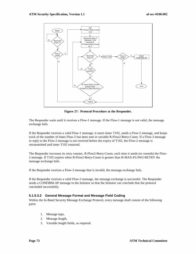
ATM Security Specification, Version 1.1 af-sec-0100.002
Page 73 ATM Technical Committee
Set R-Flow2-Retry-Count
to 0
(Re)send Flow-2(Re)start T102
Increment R-Flow2-Retry-Count
by 1
ReceivedFlow-3?
T102expired?
R-Flow2-Retry-Countgreater than
R-MAX-FLOW2-RETRY?
Failed
Flow-3Valid?
Stop T102
N
Y
N
Y
N
N
Y
Begin
ReceivedFlow-1?
Flow-1Vaild?
Y
N
Y
Y
N
End
SendCONFIRM-AP
Figure 27: Protocol Procedure at the Responder.
The Responder waits until it receives a Flow-1 message. If the Flow-1 message is not valid, the messageexchange fails.
If the Responder receives a valid Flow-1 message, it starts timer T102, sends a Flow-2 message, and keepstrack of the number of times Flow-2 has been sent in variable R-Flow2-Retry-Count. If a Flow-3 messagein reply to the Flow-2 message is not received before the expiry of T102, the Flow-2 message isretransmitted and timer T102 restarted.
The Responder increases its retry counter, R-Flow2-Retry-Count, each time it sends (or resends) the Flow-2 message. If T102 expires when R-Flow2-Retry-Count is greater than R-MAX-FLOW2-RETRY themessage exchange fails.
If the Responder receives a Flow-3 message that is invalid, the message exchange fails.
If the Responder receives a valid Flow-3 message, the message exchange is successful. The Respondersends a CONFIRM-AP message to the Initiator so that the Initiator can conclude that the protocolconcluded successfully.
5.1.5.3.2 General Message Format and Message Field CodingWithin the In-Band Security Message Exchange Protocol, every message shall consist of the followingparts:
1. Message type,2. Message length,3. Variable length fields, as required.

ATM Security Specification, Version 1.1 af-sec-0100.002
Page 74 ATM Technical Committee
Fields 1 and 2 are common to all of the messages and shall always be present, while field 3 is specific toeach message type. This organization is illustrated in Figure 28.
Message type 1
Message length 2
Message length (continued) 3
Variable length information elementsas required
4,etc.
Figure 28: General Message Organization.
5.1.5.3.2.1 Message Type
The purpose of the message type is to identify the function of the message being sent. The message type isthe first part of every message. The message type is coded as shown in Figure 29.
8 7 6 5 4 3 2 1 OctetsMessage Type 1
Figure 29: Message Type.
Message Type (Octet 1)Bits Meaning
8 7 6 5 4 3 2 10 0 1 - - - - - In-band security message0 0 1 0 0 0 0 1 FLOW1-3WE0 0 1 0 0 0 1 0 FLOW2-3WE0 0 1 0 0 0 1 1 FLOW3-3WE0 0 1 1 0 0 0 1 CONFIRM-AP0 0 1 1 0 0 1 0 FAULT
Note - Although these message types are for in-band messages only, the codepoints were chosen so as notto overlap with the signaling codepoints for message type.
5.1.5.3.2.2 Message Length
The purpose of the message length is to identify the length of the contents of a message. It is the binarycoding of the number of octets of the message contents, excluding the octets used for “message type” andfor the message length indicator itself.
The message length is the second field of every message. The message length is a 16-bit value, coded asshown in Figure 30.
8 7 6 5 4 3 2 1 Octets
Message length 1
Message length (continued) 2
Figure 30: Message Length.

ATM Security Specification, Version 1.1 af-sec-0100.002
Page 75 ATM Technical Committee
5.1.5.3.2.3 Variable Length Information Elements
5.1.5.3.2.3.1 Security Services Information Element
The Security Services Information Element (SSIE) is defined in Section 5.1.3 of this specification. Whenin-band messaging is used, the SME Flow Indicator in the SSIE, defined in section 5.1.3.2.5, shall beignored.
5.1.5.3.2.3.2 Cause Information Element
The Cause information element format defined in Q.2931 [24] shall be used for transporting cause codeswithin the context of the In-Band Message Exchange Protocol. Refer to Section 5.1.5.3.6 for causevalues.
5.1.5.3.3 Message Contents for In-Band SME Messages
5.1.5.3.3.1 Flow 1-3WE
This message is sent from the initiator to the responder to initiate the three-way security messageexchange.
Message Type: Flow1-3WE
Field or InformationElement
Reference Length
Message Type Section 5.1.5.3.2.1 1
Message Length Section 5.1.5.3.2.2 2
Security ServicesInformation Element
Section 5.1.3 12 -65535
5.1.5.3.3.2 Flow2-3WE
This message is sent from the responder to the initiator in response to Flow1-3WE.
Message Type: Flow2-3WE
Field or InformationElement
Reference Length
Message Type Section 5.1.5.3.2.1 1
Message Length Section 5.1.5.3.2.2 2
Security ServicesInformation Element
Section 5.1.3 12 -65535
5.1.5.3.3.3 FLOW3-3WE
This message is sent from the initiator to the responder in response to FLOW2-3WE.

ATM Security Specification, Version 1.1 af-sec-0100.002
Page 76 ATM Technical Committee
Message Type: FLOW3-3WE
Field or InformationElement
Reference Length
Message Type Section 5.1.5.3.2.1 1
Message Length Section 5.1.5.3.2.2 2
Security ServicesInformation Element
Section 5.1.3 12 -65535
5.1.5.3.3.4 CONFIRM-AP
This message is sent from the responder to the initiator in response to FLOW3-3WE. When the initiatorreceives the CONFIRM-AP message, it concludes that the responder received FLOW3-3WE and theprotocol completed successfully. This message is an integral part of the three-way security messageexchange procedure because its purpose is to provide notification to the initiator (i.e., calling user) that theresponder received the Flow-3 and the initiator may begin transmitting data.
Message Type: CONFIRM-AP
Field or InformationElement
Reference Length
Message Type Section 5.1.5.3.2.1 1
Message Length Section 5.1.5.3.2.2 2
5.1.5.3.3.5 Fault
In error scenarios, this message is used to carry cause data (identifying the error) from the partner thatdetected the error to the other remote partner.
Message Type: FAULT
Field or InformationElement
Reference Length
Message Type Section 5.1.5.3.2.1 1
Message Length Section 5.1.5.3.2.2 2
Cause Refer to Q.2931 [24] 4 - 34
5.1.5.3.4 Timer DefinitionsThe following is a description of the timers that are used for the in-band operation of the three-waysecurity message exchange protocol. The values of these timers can be found in Section 5.1.5.3.5, Table 7.
1. T100: This timer is used by the Initiator of the protocol to determine whether it needs to resend Flow-1 to the Responder. The timer is started when the Initiator sends Flow-1. If the Initiator has notreceived Flow-2 before the timer expires, then the Initiator resends Flow-1 and starts the timer again.The timer is stopped when a Flow-2 message is received.
2. T101: This timer is used by the Initiator of the protocol to ensure that it is waiting as long as theResponder is present and is potentially resending Flow-2 to indicate that the partner has not receivedFlow-3 from the Initiator. The timer is started the first time the Initiator sends Flow-3. As long as thistimer has not expired, the receipt of Flow-2 triggers the sending of Flow-3.
3. T102: This timer is used by the Responder in the protocol to determine whether it needs to resendFlow-2 to the Initiator. The timer is started when the Responder sends Flow-2. If the Responder has

ATM Security Specification, Version 1.1 af-sec-0100.002
Page 77 ATM Technical Committee
not received Flow-3 before the timer expires, then the Responder resends Flow-2 to the Initiator andstarts the timer again. The timer is stopped when a Flow-3 message is received.
The following variables (retry counters) are used in conjunction with the timers used in the protocol.
1. I-Flow1-Retry-Count: This variable is used in conjunction with timer T100 by the Initiator of theprotocol and counts the number of times that Flow-1 has been sent. Flow-1 may be sent up to amaximum of I-MAX-FLOW1-RETRY times.
2. R-FLOW2-Retry-Count: This variable is used in conjunction with timer T102 by the Responder in theprotocol and counts the number of times that Flow-2 has been sent. Flow-2 may be sent up to amaximum of R-MAX-FLOW2-RETRY times.
The following is a description of the constants that are used in conjunction with the retry counter variablesused in the protocol. The values of these constants can be found in Section 5.1.5.3.5, Table 8.
1. I-MAX-FLOW1-RETRY: This constant indicates the maximum number of times that the Initiatormay try to resend Flow-1 to the Responder.
2. R-MAX-FLOW2-RETRY: This constant indicates the maximum number of times that the Respondermay try to resend Flow-2 to the Initiator.
5.1.5.3.5 Timer ValuesThe protocols for in-band (user plane-based) security message exchange use a number of timers in theirprocedures. These timers, and their values, are summarized in Table 7:
Table 7: Timers for In-Band Security Message Exchange.
Timer Name Timer Value
P_Wait 600 seconds
T100 3 seconds
T101 9 seconds
T102 3 seconds
In addition, the in-band security message exchange protocols use a number of constants. These constantsand their values are summarized in Table 8.
Table 8: Constant Values for In-Band Security Message Exchange.
Constant Name Constant Value
I_MAX_FLOW1_RETRY 2
R_MAX_FLOW2_RETRY 2
5.1.5.3.6 Protocol Error HandlingDetailed error handling procedures are implementation dependent. However, capabilities facilitating theorderly treatment of error conditions provided for in this section shall be provided in eachimplementation.
When the Initiator or Responder detects an error, it sends a FAULT message to its partner to report theerror, enters the failed state, and aborts. All errors are defined to be unrecoverable errors. The protocolaborts upon sending or receiving a FAULT message.

ATM Security Specification, Version 1.1 af-sec-0100.002
Page 78 ATM Technical Committee
For SVC-initiated calls in the failed state, the security agent shall clear the call. Error recovery for PVCinitiated calls is implementation specific.
A “Cause” information element describes the reason for an error and provides diagnostic information.This information element is carried in the FAULT message. The Cause information element may berepeated in a FAULT message.
The following cause codes are defined.
In-Band Message Exchange Cause Codes
Number Meaning21 call rejected (Note 1)
47 resource unavailable
63 service or option not available
96 mandatory information element missing
97 message type non-existent or not implemented
100 invalid information element contents
102 recovery on timer expiry
111 protocol error, unspecified
Note 1:An indication of the security protocol failure shall be included in the Diagnostics field of the Cause IEwhen the cause value = “#21, call rejected.” This indication shall be the rejection reason “securityexception” as defined in [4].
5.1.6 Security Information Exchange Error ProcessingThe following text applies when security message exchange occurs in signaling, in-band, or both.
When errors occur in establishing or maintaining a security service on a specific VC, the VC must be putinto a state where User Data transport is not supported. For establishing or established VCs this isaccomplished by clearing the call. When clearing a call based on failure of a security agent to establish ormaintain a security service, an appropriate Cause code will be chosen by the security agent that is involvedwith the fault, and a diagnostic is provided that provides adequate information for the peer security agentto understand the nature of the fault condition.
Security diagnostics are specific to the types of error conditions that can happen within a security agentand are limited to 28 octets in length. The amount of information that is disclosed in a security agentdiagnostic may have a security impact, and as such each diagnostic has a mandatory section and optionalsections that provide more detail on the condition that generated the error.
1. Missing Required Security Information Element. When this error condition occurs, the call is cleared with Cause code # 96 “MandatoryInformation Element Missing” (see Q.2931 [24]), and the diagnostic will be at most 28 octets ofa valid SSIE. A 4-octet SSIE header is mandatory. Optionally, the diagnostic can contain validSAS segments that will declare to the originator the type of security service that is required by thesecurity agent. When providing SASs, the security agent can use existing fields to provideadditional information, such as the security agent’s region and role bits.

ATM Security Specification, Version 1.1 af-sec-0100.002
Page 79 ATM Technical Committee
2. Security Protocol Processing Error. When this error condition occurs, the call is cleared with Cause code #21 “Call Rejected.” SeeQ.2931 [24] for the Cause Information Element format. The diagnostic will be at most 28 octetsof a valid SSIE. A 4-octet SSIE header is mandatory. Optionally, the diagnostic can containvalid SAS segments which will indicate which SAS was being acted on when the processingerror occurred. The SAS may include the Relative ID of the SAS that generated the error.
3. Security Policy Violation.When this error condition occurs, the call is cleared with Cause code #21 “Call Rejected.” SeeQ.2931 [24] for the Cause Information Element format. The diagnostic will be at most 28 octetsof a valid SSIE. This diagnostic should contain valid SAS segments which indicate the servicethat is not allowable based on the security policy that was violated. The SAS may include theRelative ID of the SAS that generated the error.
Reporting this specific error condition is optional, as local policy may want to minimize the amount ofinformation disclosed when a security error occurs. When reporting this specific error condition is notpossible, a general “Security Protocol Processing Error” should be reported.
5.1.7 Security OAM Cells
5.1.7.1 Overview of ATM Layer OAM Cell FlowsAt the ATM layer, two OAM flows are defined: F4 (virtual path level) and F5 (virtual channel level),which are used for the operation and maintenance of connections. F4 flow is for virtual path connections(VPCs) and F5 flow is for virtual channel connections (VCCs). F4 and F5 flows are for all types of ATMconnections. At the ATM layer, the F4 and F5 flows are carried via OAM cells. F4 and F5 flows are bi-directional. In all cases, OAM cell flows must conform to the traffic contract for their respectiveVCC/VPCs. A detailed description of OAM flows and functions is given in [23].
Note: These mechanisms rely on sufficient bandwidth to sustain OAM cell flows. If sufficient bandwidthis not provided, loss or corruption of user data can occur, and errors may arise in the security mechanismitself.
Table 9: OAM Cell Type and Function Identifiers.
OAM Cell Type Codepoint Function Type Codepoint
Fault management 0001 AISRDI
Continuity checkLoopback
0000000101001000
Performance management 0010 Forward monitoringBackward monitoring
Monitoring & reporting
000000010010
Activation/Deactivation 1000 Performance monitoringContinuity check
00000001
System management 1111 Security – non-real-timeSecurity – real-time
00010010
The OAM cell formats for ATM layer OAM flows are shown in Figure 31. The OAM cell type (4-bit)field indicates the type of management function performed by the OAM cell. Currently, four OAM typesare defined: fault management, performance management, activation/deactivation, and systemmanagement. The function type (4-bit) field indicates the function performed by the OAM cell within

ATM Security Specification, Version 1.1 af-sec-0100.002
Page 80 ATM Technical Committee
thecell type. Table 9 shows the codepoints assigned for the OAM cell type field and the function typefield. The function specific field (45 octets) carries the information related to the actual function of theOAM flow. The reserved (6-bit) field is not used and left for future use. The error detection code (EDC)field carries a CRC-10 error detection code computed over the cell data payload.
5.1.7.1.1 F4 Flow of OAM CellsThe virtual path connection (VPC) operational information is carried via the F4 flow OAM cells. Thereare two types of F4 flows: end-to-end F4 flow and segment F4 flow. End-to-end F4 flows are terminated atthe endpoints of a VPC and segment F4 flows are terminated at the connecting points terminating a VPCsegment. A VPC segment is defined as either a single VPC link or a concatenation of multiple VPC links.Multiple VPC segments can be defined along a VPC path but they cannot overlap.
End-to-end and segment F4 flow OAM cells are passed unmodified by all intermediate nodes.Intermediate nodes can insert new F4 flow OAM cells. However, the end-to-end F4 flow OAM cells areremoved only by the endpoints of the VPC, and the segment F4 flow OAM cells are removed only by theVPC segment terminating points.

ATM Security Specification, Version 1.1 af-sec-0100.002
Page 81 ATM Technical Committee
ATM Cell Header ATM Cell Payload
GFCOAMCellType
PTIVCIVPI HEC ReservedCLP
FunctionType
Function-Specific FieldEDC
(CRC-10)**
4 bits 4 bits 45 octets 6 bits 10 bits
a) F4 Flow (VP-level service)
same asuser’s cell
VCI=3 (Segment)VCI=4 (End-to-end)l
GFCOAMCellType
PTIVCIVPI HEC ReservedCLP
FunctionType
Function-Specific FieldEDC
(CRC-10)**
4 bits 4 bits 45 octets 6 bits 10 bits
ATM Cell Header ATM Cell Payload
b) F5 Flow (VC-level service)
same asuser’s cell
PTI=100 (Segment)PTI=101 (End-to-end)l
** G(x) = 1 + x + x4 + x5 + x9 + x10
Figure 31: F4 and F5 OAM Cells.
F4 flow OAM cells follow exactly the same physical route as the user’s data cells of the VPC. These OAMcells have the same VPI value as the user’s data cells of the VPC and are identified by pre-assigned VCIvalues. The same pre-assigned VCI values are used for both directions of the F4 flows. Two unique VCIvalues are used for every VPC as shown in Figure 31. The VCI value = 4 is used to identify end-to-end F4flows and the VCI value = 3 is used to identify segment F4 flows.
5.1.7.1.2 F5 Flow of OAM CellsThe virtual channel connection (VCC) operational information is carried via the F5 flow OAM cells.There are two types of F5 flows: end-to-end F5 flow and segment F5 flow. End-to-end F5 flows areterminated at the endpoints of a VCC and segment F5 flows are terminated at the connecting pointsterminating a VCC segment. A VCC segment is defined as either a single VCC link or a concatenation ofmultiple VCC links. Multiple VCC segments can be defined along a VCC path but they cannot overlap.
End-to-end and segment F5 flow OAM cells are passed unmodified by all intermediate nodes.Intermediate nodes can insert new F5 flow OAM cells. However, the end-to-end F5 flow OAM cells are

ATM Security Specification, Version 1.1 af-sec-0100.002
Page 82 ATM Technical Committee
removed only by the endpoints of the VCC, and the segment F5 flow OAM cells are removed only by theVCC segment terminating points.
F5 flow OAM cells follow exactly the same physical route as the user’s data cells of the VCC. TheseOAM cells have the same VPI/VCI values as the user’s data cells of the VCC and are identified by pre-assigned codepoints of the payload type identifier (PTI). The same pre-assigned VCI values are used forboth directions of the F5 flows. Two unique PTI values are used for every VCC as shown in Figure 31.The PTI value = 5 (101) is used to identify end-to-end F5 flows and the PTI value = 4 (100) is used toidentify segment F5 flows.
5.1.7.2 Security OAM Cell FormatsTwo Security OAM cell types are defined—one for non-time-critical processes (called non-real-time), andone for time-critical processes (called real-time). The distinction is to differentiate cells that can beprocessed independently of the user traffic from those that have direct impact on user traffic. The SKEand SKC cells, defined in sections 5.1.7.2.1.1 and 5.1.7.2.2.1, are examples of non-real-time and real-time security OAM cells, respectively. The generic format for security OAM cells is shown in Figure 32.
Bits
8 7 6 5 4 3 2 1 Octets
GFC/VPI [11:8] VPI [7:4] 1
VPI [3:0] VCI [15:12] 2
VCI [11:4] 3
VCI [3:0] PTI CLP=0 4
HEC [7:0] 5
1 1 1 1 Function Type 6
Relative ID Function ID 7
Security Function Specific 8-51
0 0 0 0 0 0 CRC [9:8] 52
CRC [7:0] 53
Figure 32: Generic Security OAM Cell Format.
Notes:
1) For VCCs the PTI field is set to 101 (binary).
2) For VPCs the VCI field is set to 0004 (hex).
3) The CLP bit is always set to 0.
4) For non-real-time security OAM cells, the Function Type field is set to 0001 (binary).
5) For real-time security OAM cells, the Function Type field is set to 0010 (binary).
6) The use of the Relative ID field is defined in Section 5.1.7.3.
7) The use of the Function ID field is described in Table 10 and Table 11.

ATM Security Specification, Version 1.1 af-sec-0100.002
Page 83 ATM Technical Committee
5.1.7.2.1 Non-Real-Time Security OAM Cell FormatsNon-Real-Time (NRT) security OAM cells are defined as having an OAM function type of 0001 (binary).Up to 16 NRT cell types are possible, as defined by the Function ID field. The code points for theFunction ID field for NRT security cells are defined in Table 10.
Table 10: Function ID Code Points for Non-Real-Time Security OAM Cells.
Function ID(binary)
Security Function
0001 Data Confidentiality Session Key Exchange (SKE)
0010 Data Integrity Session Key Exchange (SKE)
all others not defined
5.1.7.2.1.1 Data Confidentiality SKE OAM Cell Format
The format of the Data Confidentiality SKE OAM Cell is defined in Figure 33.
Bits
8 7 6 5 4 3 2 1 Octets
GFC/VPI [11:8] VPI [7:4] 1
VPI [3:0] VCI [15:12] 2
VCI [11:4] 3
VCI [3:0] PTI CLP=0 4
HEC [7:0] 5
1 1 1 1 Function Type = 0001 6
Relative ID Function ID = 0001 7
Bank ID Reserved 8
Reserved 9
Key Number (KN) 10-13
Encrypted Session Key (ESK) 14-45
Reserved 46-51
0 0 0 0 0 0 CRC [9:8] 52
CRC [7:0] 53
Figure 33: Session Key Exchange (SKE) OAM Cell Format.
Notes:
1) The use of the Relative ID field is defined in Section 5.1.7.3.
2) The Bank ID field is an alternating pattern of 0 hex or F hex, for successive key updates.
3) The key number (KN) field, a 32-bit field, indicates the key number associated with the new sessionkey. Each session key is assigned a number. The first session key to be exchanged by the session keyupdate protocol is assigned 1; the second session key is assigned 2, and so forth. The KN is a fieldwhich is used by the key update protocol to ensure freshness, uniqueness, and ordering of session keyupdates and to synchronize the initiator and responder to the same session key.

ATM Security Specification, Version 1.1 af-sec-0100.002
Page 84 ATM Technical Committee
4) The Encrypted Session Key (ESK), a 256-bit field, contains the next session key encrypted using themaster key for the connection. For cases when the session key being transported is less than 256 bitsin length, it is contained in the least significant bits of the ESK field, with the most significant bitsbeing padded with zeros (before encryption).
5) Reserved octets are set to 6A hex, reserved bit fields less than 1 octet in length are set to all zeros.
6) The reserved bits included after the 4-bit Bank ID field are provided so that the KN and ESK fieldsare aligned on 16 bit boundaries, to simplify high speed implementations.
5.1.7.2.1.2 Data Integrity SKE OAM Cell Format
The format of the Data Integrity SKE OAM Cell is defined in Figure 33, except that the Function ID fieldis set to 0010 (binary). When using HMAC, the next session key length is 256 bits or the length of theprevious session key, whichever is less.
5.1.7.2.2 Real Time Security OAM Cell FormatsReal Time (RT) security OAM cells are defined as having an OAM function type of 0010 (binary). Up to16 RT cell types are possible, as defined by the Function ID field. The code points for the Function IDfield for RT security cells are defined in Table 11.
Table 11: Function ID Code Points for Real Time Security OAM Cells.
Function ID(binary)
Security Function
0001 Data Confidentiality Session Key Changeover (SKC)
0010 Data Integrity Session Key Changeover (SKC)
all others not defined
5.1.7.2.2.1 Data Confidentiality SKC OAM Cell Format
The format of the Data Confidentiality SKC OAM Cell is defined in Figure 34.

ATM Security Specification, Version 1.1 af-sec-0100.002
Page 85 ATM Technical Committee
Bits
8 7 6 5 4 3 2 1 Octets
GFC/VPI [11:8] VPI [7:4] 1
VPI [3:0] VCI [15:12] 2
VCI [11:4] 3
VCI [3:0] PTI CLP=0 4
HEC [7:0] 5
1 1 1 1 Function Type = 0010 6
Relative ID Function ID = 0001 7
Bank ID Reserved 8
Reserved 9
Key Number (KN) 10-13
State Vector (SV) 14-21
Reserved 22-51
0 0 0 0 0 0 CRC [9:8] 52
CRC [7:0] 53
Figure 34: Session Key Changeover (SKC) OAM Cell Format.
Notes:
1) The use of the Relative ID field is defined in Section 5.1.7.3.2) The Bank ID field is an alternating pattern of 0 hex or F hex for successive key updates.3) The key number (KN) field, a 32-bit field, indicates the key number associated with the new session
key. Each session key is assigned a number. The first session key to be exchanged by the session keyupdate protocol is assigned 1, the second session key is assigned 2, and so forth.
4) The State Vector (SV) contains the new state vector when using the counter mode of the DataConfidentiality service, or it is set to all zeros otherwise.
5) Reserved octets are set to 6A hex, reserved fields less than 1 octet in length are set to all zeros.6) The reserved bits included after the 4-bit Bank ID field are provided so that the KN and SV fields are
aligned on 16 bit boundaries, to simplify high speed implementations.
5.1.7.2.2.2 Data Integrity SKC OAM Cell Format
The format of the Data Integrity SKC OAM Cell is defined in Figure 34, except that the Function ID fieldis set to 0010 (binary). The SV field shall be set to zero.
5.1.7.3 Use of the Security OAM Cell Relative ID FieldThe security OAM cell’s relative ID (or RID) field is used to support symmetric nesting of security agentsand/or security services. Security OAM cells provide a means of communication between security agentsthroughout the lifetime of a connection. The relative ID field provides the mechanism to indicate whichsecurity agent a particular OAM cell applies to, when nesting is employed. Up to 16 layers of nesting aresupported.

ATM Security Specification, Version 1.1 af-sec-0100.002
Page 86 ATM Technical Committee
There are several potential uses for nested security agents. The primary one is to provide differentsecurity “domains” within a network, where an inner domain might provide different securitycharacteristics than an outer domain. By allowing nesting, users in the outer domain can share the samenetwork as the inner domain users. Nesting can also be used to combine security functions that happen touse separate security agents (e.g., privacy and integrity). Figure 35 shows an example of nested securityagents and the effect on the relative id (RID) field.
Security Agent DSecurity Agent CSecurity Agent BSecurity Agent A
Security Domain A
Security Domain B
RID = 0001
RID = 0000
PlaintextInterface
CiphertextInterface
PlaintextInterface
PlaintextInterface
PlaintextInterface
CiphertextInterface
CiphertextInterface
CiphertextInterface
RID = 0000
RID = 0000RID = 0000
RID = 0001 RID = 0000RID = 0000
Figure 35: Example of Nested Security Agents.
The procedures for processing security OAM cells are described in Sections 5.1.7.3.1, 5.1.7.3.2, and5.1.7.3.3. These procedures apply only to those security agents that insert or terminate security OAM cellsfor purposes of key update or cryptographic resynchronization. Security agents not performing thesefunctions shall pass security OAM cells transparently.
Implementations containing multiple security services in a single physical device, e.g. integrity andencryption, shall treat each service as a separate logical entity with regards to RID processing.
A security agent contains two interfaces: plaintext and ciphertext. The plaintext interface is theinterface over which the “unprotected” traffic is transmitted or received. A security agentreceives “unprotected” ATM traffic on its plaintext interface, applies security services to thetraffic, and forwards the “protected” traffic via the ciphertext interface. A security agent receivesprotected ATM traffic on its ciphertext interface, removes the security protection, and forwardsthe “unprotected” traffic over its plaintext interface. Security OAM cells flow in both theplaintext-to-ciphertext direction and ciphertext-to-plaintext direction. The procedures forprocessing the relative ID field depend on the direction of the Security OAM cell flow.
5.1.7.3.1 Initiation of Security OAM CellsThe following procedures apply to source security agents that insert security OAM cells.
Security OAM cells are introduced by security agents through the ciphertext interface. When asecurity OAM cell is injected into the cell stream by a security agent (for cryptographicresynchronization or key update purposes), the relative ID shall be set to zero.

ATM Security Specification, Version 1.1 af-sec-0100.002
Page 87 ATM Technical Committee
5.1.7.3.2 Processing for Security OAM Cells Received on the Plaintext InterfaceSecurity OAM cells may be received on the plaintext side of a security agent if there are two ormore nested pairs of security agents providing confidentiality or integrity services on a givenconnection. A security agent which receives a Security OAM cell on its plaintext interface, withthe Function ID matching the service the source SA is providing, shall increment the relative IDby one for each such matching Function ID, compute a new CRC-10 over the cell contents,circumvent the security function, and forward the cell to the ciphertext interface. The relativeorder of the security OAM cell and other cells on the connection shall not be perturbed. If therelative ID field of a received security OAM cell contains all ones, the cell is discarded.
5.1.7.3.3 Processing for Security OAM Cells Received on the Ciphertext InterfaceA Security OAM cell received on the ciphertext interface is intended for the security agent if therelative ID field is set to zero. If the relative ID is set to zero the security agent shall remove thesecurity OAM cell from the cell stream and use its contents to perform the security OAMfunction. If the relative ID is set to a value other than zero, the security agent shall decrementthe relative ID by one for each service it terminates, compute a new CRC-10 over the cellcontents, circumvent the security function, and forward the cell through the plaintext interface.The relative order of the security OAM cell and other cells on the connection shall not beperturbed.
5.2 Key Exchange
5.2.1 Key Exchange Infrastructure and MechanismsThe ATM key exchange protocol is described in the context of “security message exchange protocol” inSection 5.1. Key exchange is performed by generating initial session keys for each direction in the VC anda shared master key. These keys are encrypted for exchange using an Initial Key Exchange Key. Whenusing a public key encryption algorithm such as RSA for key exchange, the Initial Key Exchange Key isthe public key of the recipient. When using a key development algorithm such as Diffie-Hellman, theInitial Key Exchange Key is a portion of the shared value developed by the algorithm from the users’public keys. When using a symmetric key algorithm, the Initial Key Exchange Key is a shared secret keyestablished prior to key exchange.
5.2.2 Key Exchange AlgorithmsKey exchange is performed using either symmetric (secret) key algorithms such as DES or asymmetric(public) key algorithms such as RSA. If a symmetric key algorithm is used, the two nodes must havealready established a shared secret key. With asymmetric algorithms, on the other hand, each node needonly know the public key of the other node.
Note that the generation, distribution, and storage of these (usually long-lived) secret, private, or publickeys is outside the scope of this specification.
Associated with each algorithm is a codepoint that is used for identification when negotiating securityoptions. These codepoints are listed in Section 7. Procedures for using user-defined algorithm codepointsare also described in Section 7.
The following apply when performing key exchange:

ATM Security Specification, Version 1.1 af-sec-0100.002
Page 88 ATM Technical Committee
• When performing user plane key exchange, one of the authentication and key exchange protocolsdescribed in Section 5.1 shall be used.
• When performing key exchange, an authentication algorithm (either listed in Section 3.1 or userdefined) shall be used.
5.2.2.1 Asymmetric Algorithms for Key ExchangeThe following asymmetric (public-key) algorithms are defined in this specification for key exchange.
Algorithm Normative Reference
RSA [27]
Diffie-Hellman Section 8.6.4
ECKAS-DH Section 8.7.5
For Diffie-Hellman Key Exchange, the size of the modulus (p) shall be one of the following: 512, 768,1024, or 2048 bits.
5.2.2.2 Symmetric Algorithms for Key ExchangeThe following symmetric (secret-key) algorithms are defined in this specification for key exchange.
Algorithm Normative Reference
DES (in CBC mode) [7], [8]
DES40* (in CBC mode) Section 8.5
Triple DES (in CBC mode) [7], [8]
FEAL (in CBC mode) [28], [29], [8]
*Although a codepoint for this mode is assigned, this mode is deprecated.
5.2.3 Generation of Master KeysA Master Key is a key used between security agents for encrypting and decrypting session keys after initialconnection establishment. Master Keys are generated during the security message exchange protocoldescribed in Section 5.1. A single Master Key is used for both full duplex and simplex (e.g., point-to-multipoint) calls. Master Keys can be developed with public key encryption algorithms, e.g., RSA, or withkey development algorithms, e.g., Diffie-Hellman. The procedures for generating the Master Key withpublic key encryption algorithms and key development algorithms are slightly different. The maximumsize of a Master Key is 256 bits.
5.2.3.1 Master Keys on Point-To-Point ConnectionsTo develop the Master Key for point-to-point connections using a public key encryption algorithm, e.g.,RSA, 128-bit random values are selected by both the initiator and responder. These 128-bit values areexchanged in the Master Key octet group of the Confidential Parameters (Section 7.3.1). The exchangedvalues are decrypted and concatenated to form the Master Key. The concatenation is performed asfollows: the initiator value forms the most significant or leftmost half, and the responder value forms theleast significant or rightmost half.
To develop the Master Key for point-to-point connections using a key development algorithm, e.g., Diffie-Hellman, the low-order 256 bits of the resultant shared secret value is the Master Key. The Master Key

ATM Security Specification, Version 1.1 af-sec-0100.002
Page 89 ATM Technical Committee
octet group is not required, and will not be included in the Confidential Parameters, and will be ignored ifreceived. To accommodate this procedure, and also for security reasons, the modulus size for the Diffie-Hellman algorithm shall be at least 512 bits, and the modulus size for the Elliptic Curve Key AgreementScheme-Diffie Hellman algorithm shall be at least 150 bits. The Initial Key Exchange Key is then setequal to the Master Key value and used as input to the Zmask algorithm for encryption of the ConfidentialParameters.
5.2.3.2 Master Keys on Point-To-Multipoint ConnectionsFor the case of point-to-multipoint calls, the addition of leaf nodes is handled differently from the initialcall setup. This is because the Master Key for the connection has already been established (as describedabove), and need only be distributed to the new leaves.
When using public key encryption algorithms (e.g., RSA) the Master Key is encrypted in the responder’spublic key by the initiator and sent to the leaf as described in Section 5.1.
If the Master Key for the point-multipoint connection is encrypted using the Zmask algorithm defined inSection 8.6.4.1, then the initial key exchange key used in the encryption algorithm (as an input to thehash) for subsequent leaves after the initial call setup must be pre-established. The pre-establishment ofthis key can be performed either through manual configuration or through prior key exchange. In bothcases the encrypted Master Key for the connection is sent in the ConfPar token, along with the encryptedinitial session keys.
5.2.4 Generation of Initial Session KeysSession keys are the keys used by the encryption algorithm for the data confidentiality service, or theintegrity algorithm for the data integrity service. The two security agents involved in a security exchangerandomly create session keys, and they are encrypted and transferred using the security message exchangeprotocol. The method used to encrypt the initial session keys when using public or secret key encryptionalgorithms is different from the one used with key development algorithms.
When using public or secret key encryption algorithms or key development algorithms, Initial SessionKeys (ISKs) for confidentiality and integrity are created using a random number generator, and areexchanged in the session key octet group of the Confidential Parameters octet group. The ConfidentialParameters octet group is encrypted in the other party’s public key or the shared secret key. If using a keydevelopment algorithm, the Confidential Parameters octet group containing the ISKs is encrypted in theshared Initial Key Exchange Key. This is accomplished by performing the Zmask operation, as specifiedin Section 8.6.4.1, on the Initial Key Exchange Key and using the Zmask value to encrypt theConfidential Parameters.
For simplex calls (e.g., point-to-multipoint) only a single session key per service is needed. This key isalways provided by the SA providing security for the root on point-to-multipoint calls, and by the SAproviding security for the node which is generating the traffic on the simplex connection., i.e., the nodewhich has bandwidth allocated in the forward direction. The ConfPar token is sent in both directions forsimplex connections, but only one value is used; the other discarded. For full duplex calls, separateinitial session keys and initialization vectors shall be used in each direction.
5.2.5 Error ProcessingError processing for the key exchange service is described in the context of the security message exchangeprotocol in Section 5.1.

ATM Security Specification, Version 1.1 af-sec-0100.002
Page 90 ATM Technical Committee
5.3 Session Key Update
5.3.1 Session Key Update ProtocolWhen either party wants to use a new session key, it sends key update OAM cells within the user datastream to exchange the new session key with the remote partner and to indicate to the remote partnerwhen to start using the new session key. The key update OAM flows are end-to-end F4 flows for VPCsand end-to-end F5 flows for VCCs, respectively.
The session key update protocol involves two processes: exchanging a new session key between theinitiator and responder, and changing over from the old session key to the new session key. The firstprocess is referred to as “session key exchange” (SKE) and the second process is referred to as “sessionkey changeover” (SKC). The format for these OAM cells is defined in Section 5.1.7.
In order to change keys at high speeds, without disrupting service to the end user, two session keys arerequired: a current-key and a next-key. The next-key is delivered from the source to the destination usingthe SKE cell. The destination stores the next-key in a separate memory location until needed. The BankID or key number fields in the SKE cell are used to identify the next-key (with respect to the current key).The actual changeover occurs when the SKC cell is sent.
The process of performing key updates is independent in each direction of data flow for full duplexconnections. It is the responsibility of the source (e.g., the encrypting side of the data confidentialityservice) of each data flow to initiate the key update in its direction. In point-to-multipoint connectionsthere are one source and multiple destinations. Since point-to-multipoint connections are one-directional(from the source to destinations), only the root updates the session keys, and the same session keys areused by the root as well as all the leaves.
5.3.1.1 Session Key Exchange (SKE) ProcessThe SKE OAM cell is used to securely transfer the next session key from the source to the destination(s).Each key update uses a sequential key number for synchronization between the source and destination(s),as well as for cryptographic protection. A 32-bit numbering scheme is used, which means that 232 – 1session key updates can be performed on a connection before the key number wraps around.
The next session key is encrypted using the master key obtained during secure call establishment. This is a32-octet (256-bit) field that provides sufficient length for all currently defined algorithms. The actuallength of the information in this field is dependent on the session key length of the algorithm being used.
The SKE process is derived from the method described in [31]. The process is defined using both theMD5 and SHA-1 hash functions. The determination of which to use is negotiated during secure callestablishment.
5.3.1.1.1 SKE Processing at the Source (or Key Update Initiator)Given a shared secret “master key” that is exchanged using the authentication/key exchange protocol atconnection establishment time, the source can inform the destination(s) of a new session key that will beused for subsequent data traffic. When the source wants to send a new session key to the destination(s), itinvokes the SKE process.

ATM Security Specification, Version 1.1 af-sec-0100.002
Page 91 ATM Technical Committee
The format of the SKE OAM cell is defined in Section 5.1.7.2.1.1. The Bank ID is a 4-bit binaryindication, coded as all zeros or all ones, which indicates the bank associated with the next session key.The key number (KN) is a 4-octet field, which indicates the key number associated with the new sessionkey. Each session key is assigned a number. The first session key to be exchanged by the session keyupdate protocol is assigned 1; the second session key is assigned 2, and so forth (using binary unsignedcoding).
The key number field is used to maintain key update synchronization between the source and destination(i.e., to ensure both ends are using the same session key).
The following procedure is used to generate the SKE OAM cell. It is assumed that the source A shares asecret master key, Km,AB, with the destination B. In a point-to-multipoint connection, it is assumed that thesame master key is shared by the source and all the destinations.
A generates the new Bank ID = current Bank ID ⊕ 0F hex.
A increments its key number (i.e., KNA) by one. KNA is set to 0 at the time the connection is established.
A generates a new session key Ks,AB . This session key is generated randomly, and is checked to ensure it isnot “weak” (with respect to the data confidentiality algorithm or the data integrity algorithm).
A encrypts the session key under the master key as defined in Section 8.6.5 or 8.6.6.
Each source shall insure that the combination of the master key and the key number are locally unique foreach key update, to maintain the strength of the security. This does not include the extremely improbablecase when randomly generated master keys might happen to be identical.
A sends the Bank ID, key number (i.e., KNA), and the encrypted session key (i.e., Enc (K )K s, ABm,AB) to B in
the SKE OAM cell. The session key, Ks,AB, can have any length up to 256 bits (which is the length of theencrypted session key field of the SKE OAM cell). For cases when it is less than 256 bits long, the keyshall reside in the low-order bits and be prepended with zeroes. For Triple DES with keying option 2, thek2 key shall use the low order 64 bits, and the k1 key the next higher 64 bits.
Note that the old session key remains “active” at the source and destination(s) until session keychangeover (SKC) is performed. The SKE OAM cell may get lost and the source will not be able to detectthat (since there is no acknowledgment). To improve the probability that the session key exchange issuccessful, the source shall transmit the SKE OAM cell at least three (3) times with a fixed intervalbetween transmissions. The interval is an implementation parameter and need not be specified.
5.3.1.1.2 SKE Processing at the Destination (or Key Update Responder)Upon receipt of an SKE OAM cell, the destination B extracts the Bank ID, key number KNA, and theencrypted session key E, and performs the following steps:
Verifies the 10-bit OAM cell CRC is correct, and discards the cell if it is not.
Checks the received KNA. If this is the first session key received from A in a SKE OAM cell, the keynumber is valid. if it is greater than or equal to one. If this is not the first session key received from A in aSKE OAM cell, the key number is valid only if it is greater than the key number associated with the most

ATM Security Specification, Version 1.1 af-sec-0100.002
Page 92 ATM Technical Committee
recent (i.e., the previous) session key received from A. If these tests fail, then the SKE OAM cell isdiscarded and no further action is taken.
If the key number is valid, then B recovers the new session key by:
Mask=EK s,AB ⊕
The mask is computed as defined in section 8.6.5 using MD5, or section 8.6.6 for SHA-1.
The recovered key (or next-key) is stored in memory, until the corresponding SKC cell is received. TheBank ID, the KN, or both can be used to access the next-key.
5.3.1.2 Session Key Changeover (SKC) ProcessAfter the SKE process is completed from the source point of view (i.e., after the SKE OAM cell istransmitted multiple times), the source invokes the session key changeover process to indicate to thedestination(s) when to start using the new session key. The format of the SKC cell shall be as shownSection 5.1.7.2.2.1.
The source sends the SKC OAM cell that instructs the destination(s) to start using the new session key onthe cells following the SKC OAM cell. The SKC OAM cell carries the key number associated with thenew session key to which the destination(s) shall switch. The SKC OAM cell is sent multiple times toincrease the probability of receipt at the destination(s) in the presence of cell loss. The SKC OAM cell isnot cryptographically protected (since it does not carry any confidential information).
5.3.1.2.1 SKC Processing at the Source (or Key Update Initiator)The source performs the following steps:
1. Wait at least 1 second after sending the last SKE OAM cell before sending the corresponding SKCOAM cell, to allow the destination sufficient time to complete the SKE processing.
2. Set the Bank ID and the KN of the SKC OAM cell to the most recent values sent in the SKE OAMcell.
3. Set the State Vector (SV) of the SKC cell to all zeros, unless the counter mode of the dataconfidentiality service is being used, in which case the SV is initialized as described in Section 8.2.
4. Inject the SKC OAM cell into the connection undergoing key changeover in such a manner that thesession key(s) negotiated by the SKE process and the state vector (if applicable) are used on the nextuser cell transmitted on that connection for the confidentiality service, and the next SDU for theintegrity service.
5. Transmit the SKC OAM cell at least three (3) times with a fixed interval between transmissions. Theinterval is an implementation parameter and need not be specified. For the counter mode of theconfidentiality service, the state vector will be different each time the SKC OAM cell is sent if anyuser cells occur in the interim.

ATM Security Specification, Version 1.1 af-sec-0100.002
Page 93 ATM Technical Committee
In the case of the Integrity service, the SKC OAM cell is repeated three times, and each cell shall beinserted between SDUs.
Note that in counter mode for the confidentiality service, the SKC OAM cell is also used to perform acryptographic resynchronization as well as a key changeover. It is permissible to send an SKC OAM cellexpressly for this purpose, without any key changeover. This is accomplished by setting the Bank ID andkey number to the values currently in use.
5.3.1.2.2 SKC Processing at the Destination (or Key Update Responder)Upon receipt of an SKC OAM cell, the destination shall perform the following steps:
1. Extract the Bank ID, key number, and state vector (if applicable).
2. Verify that the 10-bit OAM cell CRC is correct, and discard the cell if it is not.
3. Use either the Bank ID or the key number to access the session key negotiated by the SKE process.
4. Initialize the state vector as described in Section 8.2.4.3, if the counter mode of the dataconfidentiality service is being used.
5. Use the session key and state vector (if applicable) for the next user data cell received on theconnection in the case of the confidentiality service or the next SDU received in the case of theintegrity service.
6. When the confidentiality service is used with resynchronization, treat further SKC OAM cellsreceived for the same key update as resyncs; otherwise ignore them.
Note that the SKC OAM cell is also used to perform a cryptographic resynchronization in the countermode case.
5.3.1.3 Session Key Exchange AlgorithmsAssociated with each algorithm is a codepoint that is used for identification when negotiating securityoptions. These codepoints are listed in Section 7. Procedures for using user-defined algorithm codepointsare also described in Section 7.
The following algorithms are defined in this specification for session key exchange.
Algorithm Normative Reference
MD5 Section 8.6.5
SHA-1 Section 8.6.6
RIPEMD-160 Section 8.6.6, [21]

ATM Security Specification, Version 1.1 af-sec-0100.002
Page 94 ATM Technical Committee
5.4 CertificatesThe security message exchange protocol described in Section 5.1 also provides for the exchange of publickey certificates.
The X.509 v1 certificate shall be used when certificate exchange is performed in the signaling channel.When certificate exchange is performed in-band (in the user data channel), one of the X.509 v1, v2, andv3 certificates shall be used.

ATM Security Specification, Version 1.1 af-sec-0100.002
Page 95 ATM Technical Committee
6 In-Band Security Message Exchange FiniteState Machine (FSM)
The Finite State Machine (FSM) described in this section specifies the intended behavior for the in-bandsecurity message exchange protocol. This FSM corresponds to the textual procedures described in Section5.1.5.3 of this specification. If there are any discrepancies between the textual procedures and the FSMdescription, the FSM description shall take precedence.
The FSM covers the procedures for the Initiator and the Responder of the security message exchange.
The FSM is described in five sections:
1. An overview of the message sequence is given in Section 6.1.
2. The FSM States are described in Section 6.2.
3. The FSM Events are described in Section 6.3.
4. The timers and constants needed to control the FSM are described in Section 6.4.
5. The FSM Specification and Description Language (SDL) diagrams are contained in Section 6.5.
6.1 Message Sequence ChartAn overview of the sequence of messages (Flow-1, Flow-2, etc.) and the use of timers for the normal caseis shown in Figure 36.

ATM Security Specification, Version 1.1 af-sec-0100.002
Page 96 ATM Technical Committee
CONFIRM-AP
T100
T102
Flow 1
Flow 2
T101
Initiator Responder
Flow 3
Figure 36: Basic Message Exchange Sequence.
6.2 FSM StatesThe FSM states for the Initiator and Responder sides are as follows. (It should be noted that the Initiatorand Responder Idle states are really one and the same state.)
Initiator States:• Idle: No requests for a secure connection are outstanding.
• Setup initiated: A secure connection has been initiated by sending a Flow-1, and Flow-2 is expected.
• Waiting for Confirmation: A Flow-3 has been sent and waiting for a CONFIRM-AP to indicate thatthe Responder has completed the message exchange.
• Operating at Initiator: The connection has been made available to the user.
• Failed: Errors have been detected.
Responder States:• Idle: No requests for a secure connection are outstanding.
• Exchanging Parameters: A Flow-2 has been sent and waiting for a Flow-3.
• Operating at Responder: The connection has been made available to the user.
• Failed: Errors have been detected.
6.3 FSM EventsThe FSM events which may be received by the Initiator and the Responder are as follows:
Events at Initiator:• Secure request: The initiator has been requested to secure a connection.

ATM Security Specification, Version 1.1 af-sec-0100.002
Page 97 ATM Technical Committee
• Valid Flow-2 received: A message was received which passed all the format requirements, wasrecognized as a Flow-2, and contains all required parameters.
• Confirm-AP received: A message was received which passed all the format requirements and wasrecognized as a CONFIRM-AP.
• T100 expires: The set time as shown in Table 7 is exceeded without receipt of a Flow-2.
• T101 expires: The set time as shown in Table 7 is exceeded without receipt of CONFIRM-AP.
• Fault received: The initiator has received a fault message from the Responder
• Invalid Flow-2 received: A Flow-2 has been received with errors.
Events at Responder:• Valid Flow-1 received: A message was received which passed all the format requirements, was
recognized as a Flow-1, and contains all required parameters.
• Valid Flow-3 received: A message was received which passed all the format requirements, wasrecognized as a Flow-3, and contains all required parameters.
• T102 expires: The set time as shown in Table 7 is exceeded without receipt of Flow-3.
• Fault received: The responder has received a fault message from the Initiator
• Invalid Flow-1 received: A Flow-1 has been received with errors.
• Invalid Flow-3 received: A Flow-3 has been received with errors.
6.4 Timers and ConstantsThe control of the FSM uses the following timers as defined in Sections 5.1.5.3.4 and 5.1.5.3.5:
• T100, started each time Flow-1 is sent or resent.
• T101, started when Flow-3 is sent (the first time).
• T102, started each time Flow-2 is sent or resent.
The control of the FSM uses the following constants as defined in Sections 5.1.5.3.4 and 5.1.5.3.5:
• I-Max-Flow1-Retry, which limits the number of times that Flow-1 is resent.
• R-Max-Flow2-Retry, which limits the number of times that Flow-2 is resent.
6.5 SDLThe detailed SDL for the Initiator and Responder is given in Figure 37.

ATM Security Specification, Version 1.1 af-sec-0100.002
Page 98 ATM Technical Committee
Flow 1
InitializeFlow1 count
ValidFlow 1
Securerequest
InvalidFlow 1
Idle
Start timerT100
Setupinitiated
Flow 2
InitializeFlow 2 count
Start timerT102
Exchangingparameters
Failed(responder)
Fault
Initiator orResponder
Flow 3
Timer T100expiry
Fault
SetupInitiated
InvalidFlow 2
> Max F1?
No
Yes
Stop timerT100
Wait forConfirm
ValidFlow 2
Start timerT101
IncrementFlow 1 count Stop timer
T100
Start timerT100
Flow 1
Setupinitiated
Fault
Failed(Initiator)
Initiator only
Failed(Initiator)

ATM Security Specification, Version 1.1 af-sec-0100.002
Page 99 ATM Technical Committee
Flow 3
ValidFlow 2
Timer T101expiry
Wait forConfirm
Fault
Stop timerT101
Operating(initiator)
CONFIRM-AP
Restart timerT101
Wait forConfirm
Failed(Initiator)
Failed(Initiator)
Initiator only
Fault
CONFIRM-AP
Stop timerT102
Timer T102expiry
InvalidFlow 3
Exchangingparameters
IncrementFlow2 count
Start timerT102
Flow 2
No
Yes
Exchangingparameters
Operating(responder)
Failed(responder)
Fault
Responder only
ValidFlow 3
Fault
> Max F2?
Failed(responder)
Figure 37: Detailed SDL for Three-Way SME Initiator and Responder Procedures.

ATM Security Specification, Version 1.1 af-sec-0100.002
Page 100 ATM Technical Committee
7 Security Service Data StructuresThis section defines the various data sections and octet groups which are used to construct the SecurityService Data Section.
7.1 Security Agent IdentifiersThis section specifies the use of “distinguished names” for initiating, responding, and explicitly targetingsecurity agents. There are two distinguished name formats specified here: the X.509 distinguished nameand ATM address of the ATM network element that hosts the security agent.
7.1.1 Initiator Distinguished Name
This octet group is part of the Security Agent Identification Section shown in Section 5.1.3.2.10.1. Thisoctet group contains the Distinguished Name (ID) of the initiating security agent in a Security MessageExchange.
Bits
8 7 6 5 4 3 2 1 Octet(s)
1 0 0 0 0 0 1 0
Initiator Distinguished Name Identifier x.1
Initiator Distinguished Name Length x.2
Initiator Distinguished Name Type x.3
Initiator Distinguished Name Value x.4 etc.
Initiator Distinguished Name Length (Octet x.2)
A binary number indicating the length in octets of the Initiator distinguishedname type and value fields, contained in octets x.3, x.4, etc.
Initiator Distinguished Name Type (Octet x.3)
8 7 6 5 4 3 2 1 Meaning0 0 0 0 0 0 0 1 X.509 Distinguished Name0 0 0 0 0 0 1 0 ATM End System Address
Initiator Distinguished Name Value (Octet x.4 etc.)
This octet group contains the value of the distinguished name (ID) of theInitiator of the Security Message Exchange Protocol.
X.509 Distinguished Name
This document does not specify naming conventions for security agents. Thecoding and length of this field shall be determined by the coding and length ofthe same names when carried in X.509 certificates–that is, according to theBasic Encoding Rules (BER, ISO 8825),with the restrictions imposed by X.509to make BER deterministic.
ATM End System Address (AESA)

ATM Security Specification, Version 1.1 af-sec-0100.002
Page 101 ATM Technical Committee
This field contains the ATM address associated with the Initiator. The addressis coded as described in ISO 8348, Addendum 2, using the preferred binaryencoding. For further details on using this field, consult Section 3.0 of [3].When these addresses need to be used in X.509 certificates, the followingASN.1 production shall be used to define the attribute used for thedistinguished name:aTMAddress ATTRIBUTE ::= {
WITH SYNTAX OCTET STRINGEQUALITY MATCHING RULE octetStringMatch
SUBSTRINGS MATCHING RULE octetSubstringsMatchID ...aTMAddress }
7.1.2 Responder Distinguished Name
This octet group is part of the Security Agent Identification Section shown in Section 5.1.3.2.10.1. Thisoctet group contains the Distinguished Name (ID) of the responding security agent in a Security MessageExchange.
Bits
8 7 6 5 4 3 2 1 Octet(s)
1 0 0 0 0 0 1 1
Responder Distinguished Name Identifier x.1
Responder Distinguished Name Length x.2
Responder Distinguished Name Type x.3
Responder Distinguished Name Value x.4 etc.
Responder Distinguished Name Length (Octet x.2)
A binary number indicating the length in octets of the Responder distinguishedname type and value fields, contained in octets x.3, x.4, etc.
Responder Distinguished Name Type (Octet x.3)
8 7 6 5 4 3 2 1 Meaning0 0 0 0 0 0 0 1 X.509 Distinguished Name0 0 0 0 0 0 1 0 ATM End System Address
Responder Distinguished Name Value (Octet x.4 etc.)
This octet group contains the value of the distinguished name (ID) of theResponder of the Security Message Exchange Protocol.
X.509 Distinguished Name
This document does not specify naming conventions for security agents. Thecoding and length of this field shall be determined by the coding and length ofthe same names when carried in X.509 certificates–that is, according to theBasic Encoding Rules (BER, ISO 8825),with the restrictions imposed by X.509to make BER deterministic.
ATM End System Address (AESA)

ATM Security Specification, Version 1.1 af-sec-0100.002
Page 102 ATM Technical Committee
This field contains the ATM address associated with the Responder. Theaddress is coded as described in ISO 8348, Addendum 2, using the preferredbinary encoding. For further details on using this field, consult Section 3.0 of[3]. When these addresses need to be used in X.509 certificates, the followingASN.1 production shall be used to define the attribute used for thedistinguished name:aTMAddress ATTRIBUTE ::= {
WITH SYNTAX OCTET STRINGEQUALITY MATCHING RULE octetStringMatch
SUBSTRINGS MATCHING RULE octetSubstringsMatchID ...aTMAddress }
7.1.3 Security Agent Distinguished Name
This octet group contains the distinguished name (ID) of the explicitly targeted security agent in aSecurity Message Exchange, as shown in Section 5.1.3.2.9.
Bits
8 7 6 5 4 3 2 1 Octet(s)
1 0 0 0 0 1 0 0
Security Agent Distinguished Name Identifier x.1
Security Agent Distinguished Name Length x.2
Security Agent Distinguished Name Type x.3
Security Agent Distinguished Name Value x.4 etc.
Security Agent Distinguished Name Length (Octet x.2)
A binary number indicating the length in octets of the Security Agentdistinguished name type and value fields, contained in octets x.3, x.4, etc.
Security Agent Distinguished Name Type (Octet x.3)
8 7 6 5 4 3 2 1 Meaning0 0 0 0 0 0 0 1 X.509 Distinguished Name0 0 0 0 0 0 1 0 ATM End System Address
Security Agent Distinguished Name Value (Octet x.4 etc.)
This octet group contains the value of the distinguished name (ID) of theSecurity Agent of the Security Message Exchange Protocol.
X.509 Distinguished Name
This document does not specify naming conventions for security agents. Thecoding and length of this field shall be determined by the coding and length ofthe same names when carried in X.509 certificates–that is, according to theBasic Encoding Rules (BER, ISO 8825),with the restrictions imposed by X.509to make BER deterministic.
ATM End System Address (AESA)

ATM Security Specification, Version 1.1 af-sec-0100.002
Page 103 ATM Technical Committee
This field contains the ATM address associated with the security agent. Theaddress is coded as described in ISO 8348, Addendum 2, using the preferredbinary encoding. For further details on using this field, consult Section 3.0 of[3]. When these addresses need to be used in X.509 certificates, the followingASN.1 production shall be used to define the attribute used for thedistinguished name:aTMAddress ATTRIBUTE ::= {
WITH SYNTAX OCTET STRINGEQUALITY MATCHING RULE octetStringMatchSUBSTRINGS MATCHING RULE octetSubstringsMatchID ...aTMAddress }
7.2 Security Service Specification SectionThe Security Service Specification Section provides a description of the security services that arerequested or supported for a particular security association. This section is optional in Flow-1 and Flow-2.It may not be used in Flow-3. If this section is used, services that are requested or supported shall bespecified in one of two ways, either using a Security Service Declaration, or using a list of specificSecurity Service Options. The Security Service Declaration is provided as a concise method of declaringto a peer or proxy security agent the services that are supported or requested on the VC. The SecurityService Option Section is designed for detailed security service declaration and negotiation. The Option isused to specify the supported or required security service. The Declaration may be used with the 2-wayand the Options may be used with the 2-way or 3-way message exchange.
Following the Security Service Options (described in Section 7.2.2), the Algorithm Description (describedin Section 7.2.3) may be used to specify in detail the specific services.
Bits
8 7 6 5 4 3 2 1 Octet(s)
1 0 0 0 1 0 0 0
Security Service Specification Section Identifier x.1
Security Service Declaration Section x.2 etc*
Security Service Option Section x.3 etc*
Security Service Algorithm Section x.4 etc*
Security Service Declaration Section (Octet Group x.2)
This optional octet group declares the specific security services that arerequested for a VC. Details are found below.
Security Service Option Section (Octet Group x.3)
This optional octet group indicates specific options for the indicated securityservice. Details are found below.
Security Service Algorithm Section (Octet Group x.4)]
This octet group describes the details of security service algorithms for theindicated security service. Details are found in section 7.2.3.

ATM Security Specification, Version 1.1 af-sec-0100.002
Page 104 ATM Technical Committee
7.2.1 Security Service DeclarationThe Security Service Declaration Section provides a minimal description of the security services that arerequested or supported by a security agent.
The Security Service Declaration shall only be contained in the SSIEs within a 2-way signaling-basedexchange. It shall not be generated in 3-way and shall be ignored if received in 3-way.
The Security Service Declaration Section is employed when communicating a security service request to aproxy security agent, or when declaring security capabilities to a peer SA.
Bits
8 7 6 5 4 3 2 1 Octet(s)
1 0 0 0 1 0 1 0
Security Service Declaration Identifier x.1
Security Service Declaration
x x x x x x x x x.2
Security Service Declaration (Octet x.2, bits 8-1)
Bit Meaning in Flow-1 from Initiator SA andin Flow-2 from Responder SA
Meaning in Flow-1from end system
Meaning in Flow-2from proxy
10 Confidentiality Service not supported not requested not provided1 Confidentiality Service supported requested provided
20 Integrity Service not supported not requested not provided1 Integrity Service supported requested provided
30 Authentication Service not supported not requested not provided1 Authentication Service supported requested provided
40 Key Exchange Service not supported not requested not provided1 Key Exchange Service supported requested provided
50 Certificate Exchange Service not supported not requested not provided1 Certificate Exchange Service supported requested provided
60 Session Key Update Service not supported not requested not provided1 Session Key Update Service supported requested provided
70 Access Control Service not supported not requested not provided1 Access Control Service supported requested provided
8- Not used

ATM Security Specification, Version 1.1 af-sec-0100.002
Page 105 ATM Technical Committee
7.2.2 Security Service Options SectionThe Security Service Options Section contains one or more octet groups, each used during security servicenegotiation to indicate whether a specific security service is required or supported. The following octetgroups are all optional and may be included in any order, but each not more than once.
In the 2-way exchange, the initiator shall indicate which security services are required for the connection.The responder shall examine the security services specification, and accept the call if it is suitable, orreject it if not.
In the 3-way exchange, the initiator shall indicate which security services are required, which securityservices can be supported if the responder requires them, and which security services are not supported forthe connection. For each service supported by the initiator, the responder may indicate if this service isrequired or not supported. For each service not supported by the initiator, the responder shall not includeany response.
When an octet group for a specific service is omitted, it shall be interpreted to mean that thecorresponding service is not required or not supported.
7.2.2.1 Data Confidentiality Service Options
Bits
8 7 6 5 4 3 2 1 Octet(s)
1 0 0 1 0 0 0 0
Data Confidentiality Service Option Identifier x.1
Data Confidentiality Service Options
x x x x x x x x x.2
Data Confidentiality Service Options (Octet x.2)
8 7 6 5 4 3 2 1 Meaning0 0 0 0 0 0 0 0 Not Supported0 0 0 0 0 0 0 1 Supported at ATM Cell Level (Note)1 0 0 0 0 0 0 1 Required at ATM Cell Level
Note: This codepoint applies only when used by the initiator in FLOW1-3WE.
7.2.2.2 Data Integrity Service Options
Bits
8 7 6 5 4 3 2 1 Octet(s)
1 0 0 1 0 0 1 0
Data Integrity Service Options Identifier x.1
Data Integrity Service Options
x x x x x x x x x.2
Data Integrity Service Options (Octet x.2)
8 7 6 5 4 3 2 1 Meaning

ATM Security Specification, Version 1.1 af-sec-0100.002
Page 106 ATM Technical Committee
0 0 0 0 0 0 0 0 Not supported0 0 0 0 0 0 0 1 Supported, with Replay / Reordering Protection (Note)0 0 0 0 0 0 1 0 Supported, without Replay / Reordering Protection (Note)1 0 0 0 0 0 0 1 Required, with Replay/Reordering Protection1 0 0 0 0 0 1 0 Required, without Replay/Reordering Protection1 0 0 0 0 1 0 0 Required, with or without Replay/Reordering Protection
(Note)Note: This codepoint applies only when used by the initiator in FLOW1-3WE.
7.2.2.3 Authentication Service Options
Bits
8 7 6 5 4 3 2 1 Octet(s)
1 0 0 1 0 0 1 1
Authentication Service Options Identifier x.1
Authentication Service Options
x x x x x x x x x.2
Authentication Service Options (Octet x.2)
8 7 6 5 4 3 2 1 Meaning0 0 0 0 0 0 0 0 Not supported0 0 0 0 0 0 0 1 Supports Authentication (Note)1 0 0 0 0 0 0 1 Requires Authentication
Note: This codepoint applies only when used by the initiator in FLOW1-3WE.
7.2.2.4 Key Exchange Service Options
Bits
8 7 6 5 4 3 2 1 Octet(s)
1 0 0 1 0 1 0 0
Key Exchange Service Options Identifier x.1
Key Exchange Service Options
x x x x x x x x x.2
Key Exchange Service Options (Octet x.2)
8 7 6 5 4 3 2 1 Meaning0 0 0 0 0 0 0 0 Not supported0 0 0 0 0 0 0 1 Supports Key Exchange (Note)0 1 0 0 0 0 0 1 Requires Key Exchange
Note: This codepoint applies only when used by the initiator in FLOW1-3WE.
7.2.2.5 Session Key Update Service Options

ATM Security Specification, Version 1.1 af-sec-0100.002
Page 107 ATM Technical Committee
Bits
8 7 6 5 4 3 2 1 Octet(s)
1 0 0 1 0 1 0 1
Session Key Update Service Options Identifier x.1
Session Key Update Service Options
x x x x x x x x x.2
Session Key Update Service Options (Octet x.2)
8 7 6 5 4 3 2 1 Meaning0 0 0 0 0 0 0 0 Not supported0 0 0 0 0 0 0 1 Supports Session Key Update (Note 1)1 0 0 0 0 0 0 1 Requires Session Key Update
Note 1: This codepoint applies only when used by the initiator in FLOW1-3WE.Note 2: The result of SKU negotiation applies to both the confidentiality and integrity services.
7.2.2.6 Access Control Service Options
Bits
8 7 6 5 4 3 2 1 Octet(s)
1 0 0 1 0 1 1 0
Access Control Service Options Identifier x.1
Access Control Service Options
x x x x x x x x x.2
Access Control Service Options (Octet x.2)
8 7 6 5 4 3 2 1 Meaning0 0 0 0 0 0 0 0 Not supported0 0 0 0 0 0 0 1 Supports Access Control (Note)1 0 0 0 0 0 0 1 Requires Access Control
Note: This codepoint applies only when used by the initiator in FLOW1-3WE to indicate that it supportsaccess control.
7.2.2.7 Certificate Exchange Service Options

ATM Security Specification, Version 1.1 af-sec-0100.002
Page 108 ATM Technical Committee
Bits
8 7 6 5 4 3 2 1 Octet(s)
1 0 0 1 0 1 1 1
Certificate Exchange Service Options Identifier x.1
Certificate Exchange Service Options
x x x x x x x x x.2
Certificate Exchange Service Options (Octet x.2)
8 7 6 5 4 3 2 1 Meaning
0 0 0 0 0 0 0 0 Not supported
0 0 0 0 0 0 0 1 Supports Certificate Exchange (Note)
1 0 0 0 0 0 0 1 Requires Certificate ExchangeNote :This codepoint applies only when used by the initiator in FLOW1-3WE.

ATM Security Specification, Version 1.1 af-sec-0100.002
Page 109 ATM Technical Committee
7.2.3 Security Service Algorithm Description SectionThe security algorithm section is used during negotiation for proposing and specifying algorithms to beused for the indicated security services. This also includes the algorithm’s mode of operation, whenappropriate. In addition, the parameters associated with each algorithm are also included.
This section may include:
• One or more octet groups for Data Confidentiality, Data Integrity, Hash, Signature, KeyExchange, and Session Key Update algorithms. Octet groups for the same service may beincluded multiple times in the order of preference selected by the initiator. Octet groups fordifferent services may be in any order.
• One or more octet groups for the Authentication, Integrity, and Confidentiality Algorithm ProfileGroups. Octet groups for the same Algorithm Profile Group may be included multiple times inthe order of preference selected by the initiator. Octet groups for different Algorithm ProfileGroups may be in any order.
Only one of the above methods shall be used for each security service. Different methods may be used fordifferent security services.
This specification allows for the use of user (or vendor) specified algorithms. If a user (or vendor)specified algorithm is used, then the optional octet group containing the user’s (or vendor’s)Organizationally Unique Identifier (OUI) shall be used. The value of the OUI is unique to the user (orvendor), and is assigned by the Institute for Electrical and Electronics Engineers (IEEE).
As defined in IEEE Std 802-1990, the OUI is a 6-hex character identifier which is also represented as a24-bit value. These 24 bits are placed in the octet groups defined in this section as follows:
• The first 8 bits of the OUI are mapped to the first octet, and so on.
• The most significant bit of the OUI is mapped to bit 8 of that first octet and the least significantbit of the OUI is mapped to bit 1 of the third octet.
• Because of the coding defined by IEEE, bit 7 of the first octet is always set to “0.”
As an example, for an OUI of ACDE48, the contents of the three octets in the security message would beas follows:
Bits
8 7 6 5 4 3 2 1 Octet(s)
1 0 1 0 1 1 0 0 1st
1 1 0 1 1 1 1 0 2nd
0 1 0 0 1 0 0 0 3rd
7.2.3.1 Data Confidentiality Algorithm
This octet group indicates an algorithm for the data confidentiality service.

ATM Security Specification, Version 1.1 af-sec-0100.002
Page 110 ATM Technical Committee
Bits
8 7 6 5 4 3 2 1 Octet(s)
1 0 1 0 0 0 0 0
Data Confidentiality Algorithm Identifier x.1
Length of Data Confidentiality Algorithm Contents x.2
Data Confidentiality Algorithm x.3
OUI x.4 (Note 1)
OUI (continued) x.5 (Note 1)
OUI (continued) x.6 (Note 1)
Data Confidentiality Mode of Operation x.7
OUI x.8 (Note 2)
OUI (continued) x.9 (Note 2)
OUI (continued) x.10 (Note 2)
Data Confidentiality Algorithm Details x.11 etc.*
Data Confidentiality Mode Details x.12 etc.*
Length of Data Confidentiality Algorithm Contents (Octet x.2)
A binary number indicating the length in octets of the data confidentialityalgorithm/mode fields, contained in octets x.3, x.4, x.5 etc.
Data Confidentiality Algorithm (Octet x.3)
8 7 6 5 4 3 2 1 Meaning0 0 0 0 0 0 0 1 DES with 56 bits effective key0 0 0 0 0 0 1 0 DES with 40 bits effective key0 0 0 0 0 0 1 1 Triple-DES with keying option 2 [7]0 0 0 0 0 1 0 0 FEAL, N=32, 64 bit key, no key block parity1 x x x x x x x User-defined data confidentiality algorithm
(the value of bits 1-7 is user-defined)
OUI (Octets x.4 - x.6)
Note 1: if the data confidentiality algorithm is “user defined,” then the IEEE OUI of thevendor or user that assigned the user-defined codepoint shall be included in these octets.Otherwise, these octets are not included.
Data Confidentiality Mode of Operation (Octet x.7)
8 7 6 5 4 3 2 1 Meaning0 0 0 0 0 0 0 0 Mode not applicable0 0 0 0 0 0 0 1 CBC0 0 0 0 0 0 1 0 Counter Mode0 0 0 0 0 0 1 1 ECB1 x x x x x x x User-defined data confidentiality mode of
operation (the value of bits 1-7 is user-defined)
OUI (Octets x.8 - x.10)

ATM Security Specification, Version 1.1 af-sec-0100.002
Page 111 ATM Technical Committee
Note 2: if the data confidentiality mode of operation is “user defined,” then the IEEEOUI of the vendor or user that assigned the user-defined codepoint shall be included inthese octets. Otherwise, these octets are not included.
Data Confidentiality Algorithm Details (Octet x.11 etc.)
These octets indicate coding details for each data confidentiality algorithm.These details are found below:
⇒ DES coding details - No further detail required
⇒ DES40 coding detailsTwo eight-octet fields are added to the data confidentiality algorithm informationelement details. The first eight octets contain a binary encoded 64-bit randomnumber. The second eight octets contain the binary encoding of that randomnumber encrypted under the DES40 key in the ECB mode.[Note: these details originally were included to satisfy certain export requirements.]
⇒ Triple DES coding details - No further detail required
⇒ FEAL coding details - No further detail required
⇒ User-defined algorithm details - Format of details specified by user
Data Confidentiality Mode Details (Octet x.12 etc.)
These octets indicate coding details for each data confidentiality mode ofoperation. These details are found below:
⇒ CBC mode coding details A 64-bit (8-octet) binary encoded value. This is the initialization vector (IV) for theCBC mode.
⇒ Counter mode coding details - No further detail required
⇒ ECB mode coding details- No further detail required
⇒ User-defined mode details - Format of details specified by user
7.2.3.2 Data Integrity Algorithm
This octet group indicates an algorithm for the data integrity service.

ATM Security Specification, Version 1.1 af-sec-0100.002
Page 112 ATM Technical Committee
Bits
8 7 6 5 4 3 2 1 Octet(s)
1 0 1 0 0 0 1 0
Data Integrity Algorithm Identifier x.1
Length of Data Integrity Algorithm Contents x.2
User Replay Algorithm
Data Integrity Algorithm x.3
OUI x.4 (Note)
OUI (continued) x.5 (Note)
OUI (continued) x.6 (Note)
Data Integrity Algorithm Details x.7 etc.*
Length of Data Integrity Algorithm Contents (Octet x.2)
A binary number indicating the length in octets of the data integrity algorithmfields, contained in octets x.3, x.4, etc.
User Defined Indicator (Octet x.3 Bit 8)
8 Meaning0 ATM Forum Defined Algorithm1 User Defined Algorithm
When a User Defined Algorithm is indicated, Bits 7-1 are user defined. The followingdefinitions of Replay/Reordering protection and Data Integrity Algorithm apply onlywhen Bit 8 indicates “ATM Forum Defined Algorithm”.
Replay/Reordering Protection Indicator (Octet x.3 Bit 7)
7 Meaning0 No replay/reordering protection provided.1 Replay/reordering protection provided.
Data Integrity Algorithm (Octet x.3 Bits 6 - 1)
6 5 4 3 2 1 Meaning0 0 0 0 0 1 HMAC-MD50 0 0 0 1 0 HMAC-SHA-10 0 0 0 1 1 HMAC-RIPEMD-1600 0 0 1 0 0 DES/CBC MAC0 0 0 1 0 1 DES40/CBC MAC0 0 0 1 1 0 Triple DES/CBC MAC0 0 0 1 1 1 FEAL/CBC MAC
OUI (Octets x.4 - x.6)
Note: if the data integrity algorithm is “user defined,” then the IEEE OUI of the vendoror user that assigned the user-defined codepoint shall be included in these octets.Otherwise, these octets are not included.

ATM Security Specification, Version 1.1 af-sec-0100.002
Page 113 ATM Technical Committee
Data Integrity Algorithm Details (Octet x.7 etc.)
These octets indicate coding details for each data integrity algorithm. Thesedetails are found below:
⇒ HMAC-MD5 coding details - No further detail required
⇒ HMAC-SHA-1 coding details - No further detail required
⇒ HMAC-RIPEMD-160 coding details - No further detail required
⇒ DES in CBC mode MAC details - No further detail required
⇒ DES-40 in CBC mode MAC details - No further detail required
⇒ Triple DES in CBC mode MAC details - No further detail required
⇒ FEAL in CBC mode MAC details- No further detail required
⇒ User-defined algorithm details - Format of details specified by user
7.2.3.3 Hash AlgorithmThis octet group indicates a hashing algorithm for the authentication service.
Bits
8 7 6 5 4 3 2 1 Octet(s)
1 0 1 0 0 1 0 0
Hash Algorithm Identifier x.1
Length of Hash Algorithm Contents x.2
Hash Algorithm x.3
OUI x.4 (Note)
OUI (continued) x.5 (Note)
OUI (continued) x.6 (Note)
Hash Algorithm Details x.7 etc.*
Length of Hash Algorithm Contents (Octet x.2)
A binary number indicating the length in octets of the hash algorithm fieldscontained in octets x.3, x.4, etc.
Hash Algorithm (Octet x.3)
8 7 6 5 4 3 2 1 Meaning0 0 0 0 0 0 0 1 MD50 0 0 0 0 0 1 0 SHA-10 0 0 0 0 0 1 1 RIPEMD-160

ATM Security Specification, Version 1.1 af-sec-0100.002
Page 114 ATM Technical Committee
1 x x x x x x x User-defined hash algorithm(the value of bits 1-7 is user-defined)
OUI (Octets x.4 - x.6)
Note: if the hash algorithm is “user defined,” then the IEEE OUI of the vendor or userthat assigned the user-defined codepoint shall be included in these octets. Otherwise,these octets are not included.
Hash Algorithm Details (Octet x.7 etc.)
These octets indicate coding details for each hash algorithm. These details arefound below:
⇒ MD5 coding details - No further detail required
⇒ SHA-1 coding details - No further detail required
⇒ RIPEMD-160 coding details- No further detail required
⇒ User-defined algorithm details - Format of details specified by user
7.2.3.4 Signature AlgorithmThis octet group indicates a signature algorithm or MAC for the Authentication Service.
Bits
8 7 6 5 4 3 2 1 Octet(s)
1 0 1 0 0 1 1 0
Signature Algorithm Identifier x.1
Length of Signature Algorithm Contents x.2
Signature Algorithm x.3
OUI x.4 (Note)
OUI (continued) x.5 (Note)
OUI (continued) x.6 (Note)
Signature Algorithm Details x.7 etc*.
Length of Signature Algorithm Contents (Octet x.2)
A binary number indicating the length in octets of the signature algorithmfields contained in octets x.3, x.4, etc.
Signature Algorithm (Octet x.3)
8 7 6 5 4 3 2 1 Meaning0 0 0 0 0 0 0 1 RSA0 0 0 0 0 0 1 0 DSA0 0 0 0 0 0 1 1 EC-GDSA0 0 0 0 0 1 0 0 ESIGN

ATM Security Specification, Version 1.1 af-sec-0100.002
Page 115 ATM Technical Committee
0 0 0 0 0 1 0 1 DES/CBC MAC0 0 0 0 0 1 1 0 DES40/CBC MAC0 0 0 0 0 1 1 1 Triple DES/CBC MAC0 0 0 0 1 0 0 0 FEAL/CBC MAC1 x x x x x x x User-defined algorithm
(the value of bits 1-7 is user-defined)
OUI (Octets x.4 - x.6)
Note: If the signature algorithm is “user defined,” then the IEEE OUI of the vendor oruser that assigned the user-defined codepoint shall be included in these octets.Otherwise, these octets are not included.
Signature Algorithm Details (Octet x.7 etc.)
These optional octets indicate coding details for each signature algorithm.These details are found below:
⇒ RSA coding details - No further detail required
⇒ DSA coding details - No further detail required
⇒ EC-GDSA coding details - No further detail required (cf. Section 8.7)
⇒ ESIGN coding details The order of k:This octet contains the binary encoding of the order of k (i.e., X, in the relation k = 2X )
⇒ DES/CBC MAC coding details - No further detail required
⇒ DES40/CBC MAC coding details - No further detail required
⇒ Triple DES/CBC MAC coding details - No further detail required
⇒ FEAL/CBC MAC coding details- No further detail required
⇒ User-defined algorithm details - Format of details specified by user
7.2.3.5 Key Exchange AlgorithmThis octet group indicates the algorithm used for key exchange.

ATM Security Specification, Version 1.1 af-sec-0100.002
Page 116 ATM Technical Committee
Bits
8 7 6 5 4 3 2 1 Octet(s)
1 0 1 0 1 0 0 0
Key Exchange Algorithm Identifier x.1
Length of Key Exchange Algorithm Contents x.2
Key Exchange Algorithm x.3
OUI x.4 (Note)
OUI (continued) x.5 (Note)
OUI (continued) x.6 (Note)
Key Exchange Algorithm Details x.7 etc.*
Length of Key Exchange Algorithm Contents (Octet x.2)
A binary number indicating the length in octets of the key exchange algorithmfields contained in octets x.3, x.4, etc.
Key Exchange Algorithm (Octet x.3)
8 7 6 5 4 3 2 1 Meaning0 0 0 0 0 0 0 1 RSA0 0 0 0 0 0 1 0 Diffie-Hellman0 0 0 0 0 0 1 1 ECKAS-DH (prime field)0 0 0 0 0 1 0 0 ECKAS-DH (characteristic 2 field)0 0 0 0 0 1 0 1 DES/CBC0 0 0 0 0 1 1 0 DES40/CBC0 0 0 0 0 1 1 1 Triple DES/CBC0 0 0 0 1 0 0 0 FEAL/CBC1 x x x x x x x User-defined key exchange algorithm
(the value of bits 1-7 is user-defined)
OUI (Octets x.4 - x.6)
Note: If the key exchange algorithm is “user defined,” then the IEEE OUI of the vendoror user that assigned the user-defined codepoint shall be included in these octets.Otherwise, these octets are not included.
Key Exchange Algorithm Details (Octet x.7 etc.)
These octets indicate coding details for each key exchange algorithm. Thesedetails are found below:
⇒ RSA coding details - No further detail required
⇒ Diffie-Hellman coding details
Diffie-Hellman public key identifier (Octet x.7a): This octet is the identifier for the Diffie-Hellman public key.
8 7 6 5 4 3 2 1 Meaning 0 0 0 0 0 0 0 1 Diffie-Hellman public key
Diffie-Hellman public key length (Octet x.7b):

ATM Security Specification, Version 1.1 af-sec-0100.002
Page 117 ATM Technical Committee
This octet specifies the length of the Diffie-Hellman public key inoctets.
Diffie-Hellman public key value (Octet x.7c etc.): This field contains the octet string representation of the Diffie-Hellman public key value. This field contains the initiator’s Diffie-Hellman public key value (X) when this information element is sent inFLOW1-3WE. This field contains the responder’s Diffie-Hellmanpublic key value (Y) when this information element is sent in FLOW2-3WE.
Diffie-Hellman modulus identifier (Octet x.8a): This octet is the identifier for the Diffie-Hellman public modulus.
8 7 6 5 4 3 2 1 Meaning 0 0 0 0 0 0 1 0 Diffie-Hellman public modulus
Diffie-Hellman modulus length (Octet x.8b): This octet specifies the length of the Diffie-Hellman public modulus inoctets.
Diffie-Hellman modulus value (Octet x.8c etc.): This field contains the octet string representation of the Diffie-Hellman public modulus value (P).
Diffie-Hellman base identifier (Octet x.9a): This octet is the identifier for the Diffie-Hellman public base.
8 7 6 5 4 3 2 1 Meaning 0 0 0 0 0 0 1 1 Diffie-Hellman public base
Diffie-Hellman base length (Octet x.9b): This octet specifies the length of the Diffie-Hellman public base inoctets.
Diffie-Hellman base value (Octet x.9c etc.): This field contains the octet string representation of the Diffie-Hellman public base value (G).
⇒ Elliptic Curve Key Agreement Scheme-Diffie Hellman Analogue (ECKAS-DH)coding details for prime fields (cf. Section 8.7.5):
ECKAS-DHp public key identifier (Octet x.7a): This octet is the identifier for the ECKAS-DHp public key.
8 7 6 5 4 3 2 1 Meaning 0 0 0 0 0 0 0 1 ECKAS-DHp public key
ECKAS-DHp public key length (Octet x.7b): This octet specifies the length of the ECKAS-DHp public key in octets.
ECKAS-DHp public key value (Octet x.7c etc.): This field contains the octet string representation of the ECKAS-DHppublic key value. This field contains the initiator’s ECKAS-DHppublic key value (aP) when this information element is sent inFLOW1-3WE. This field contains the responder’s ECKAS-DHppublic key value (bP) when this information element is sent inFLOW2-3WE.
ECKAS-DHp modulus identifier (Octet x.8a): This octet is the identifier for the ECKAS-DHp public modulus (p).
8 7 6 5 4 3 2 1 Meaning 0 0 0 0 0 0 1 0 ECKAS-DHp public modulus

ATM Security Specification, Version 1.1 af-sec-0100.002
Page 118 ATM Technical Committee
ECKAS-DHp modulus length (Octet x.8b): This octet specifies the length of the ECKAS-DHp public modulus inoctets.
ECKAS-DHp modulus value (Octet x.8c etc.): This field contains the octet string representation of the ECKAS-DHppublic modulus value (p).
ECKAS-DHp base identifier (Octet x.9a): This octet is the identifier for the ECKAS-DHp public base (P) (cf.Section 8.7).
8 7 6 5 4 3 2 1 Meaning 0 0 0 0 0 0 1 1 ECKAS-DHp public base
ECKAS-DHp base length (Octet x.9b): This octet specifies the length of the ECKAS-DHp public base inoctets.
ECKAS-DHp base value (Octet x.9c etc.): This field contains the octet string representation of the ECKAS-DHppublic base.
ECKAS-DHp Weierstrass coefficient identifier (Octet x.10a): This octet is the identifier for the ECKAS-DHp Weierstrass coefficient(a) (cf. Section 8.7).
8 7 6 5 4 3 2 1 Meaning 0 0 0 0 0 1 0 0 ECKAS-DHp Weierstrass
coefficient
ECKAS-DHp Weierstrass coefficient length (Octet x.10b): This octet specifies the length of the ECKAS-DHp Weierstrasscoefficient (a) in octets.
ECKAS-DHp Weierstrass coefficient value (Octet x.10c etc.): This field contains the octet string representation of the ECKAS-DHpWeierstrass coefficient (a).
ECKAS-DHp Weierstrass coefficient identifier (Octet x.11a): This octet is the identifier for the ECKAS-DHp Weierstrass coefficient(b) (cf. Section 8.7).
8 7 6 5 4 3 2 1 Meaning 0 0 0 0 0 1 0 1 ECKAS-DHp Weierstrass
coefficient
ECKAS-DHp Weierstrass coefficient length (Octet x.11b): This octet specifies the length of the ECKAS-DHp Weierstrasscoefficient (b) in octets.
ECKAS-DHp Weierstrass coefficient value (Octet x.11c etc.): This field contains the octet string representation of the ECKAS-DHpWeierstrass coefficient (b).
⇒ Elliptic Curve Key Agreement Scheme-Diffie Hellman Analogue (ECKAS-DH)coding details for characteristic 2 (cf. Section 8.7.5):
ECKAS-DH2 public key identifier (Octet x.7a): This octet is the identifier for the ECKAS-DH2 public key.
8 7 6 5 4 3 2 1 Meaning 0 0 0 0 0 0 0 1 ECKAS-DH2 public key
ECKAS-DH2 public key length (Octet x.7b):

ATM Security Specification, Version 1.1 af-sec-0100.002
Page 119 ATM Technical Committee
This octet specifies the length of the ECKAS-DH2 public key in octets.
ECKAS-DH2 public key value (Octet x.7c etc.): This field contains the octet string representation of the ECKAS-DH2public key value. This field contains the initiator’s ECKAS-DH2public key value (aP) when this information element is sent inFLOW1-3WE. This field contains the responder’s ECKAS-DH2public key value (bP) when this information element is sent inFLOW2-3WE.
ECKAS-DH2 field size identifier (Octet x.8a): This octet is the identifier for the ECKAS-DH2 field size (m).
8 7 6 5 4 3 2 1 Meaning 0 0 0 0 0 0 1 0 ECKAS-DH2 field size
ECKAS-DH2 field size length (Octet x.8b): This octet specifies the length of the ECKAS-DH2 field size (m) inoctets.
ECKAS-DH2 field size value (Octet x.8c etc.): This field contains the octet string representation of the ECKAS-DH2field size value (m).
ECKAS-DH2 base identifier (Octet x.9a): This octet is the identifier for the ECKAS-DH2 public base (P) (cf.Section 8.7).
8 7 6 5 4 3 2 1 Meaning 0 0 0 0 0 0 1 1 ECKAS-DH2 public base
ECKAS-DH2 base length (Octet x.9b): This octet specifies the length of the ECKAS-DH2 public base inoctets.
ECKAS-DH2 base value (Octet x.9c etc.): This field contains the octet string representation of the ECKAS-DH2public base.
ECKAS-DH2 Weierstrass coefficient (a) identifier (Octet x.10a): This octet is the identifier for the ECKAS-DH2 Weierstrass coefficient(a) (cf. Section 8.7).
8 7 6 5 4 3 2 1 Meaning 0 0 0 0 0 1 0 0 ECKAS-DH2 Weierstrass
coefficient (a)
ECKAS-DH2 Weierstrass coefficient (a) length (Octet x.10b): This octet specifies the length of the ECKAS-DH2 Weierstrasscoefficient (a) in octets.
ECKAS-DH2 Weierstrass coefficient (a) value (Octet x.10c etc.): This field contains the octet string representation of the ECKAS-DH2Weierstrass coefficient (a).
ECKAS-DH2 Weierstrass coefficient (b) identifier (Octet x.11a): This octet is the identifier for the ECKAS-DH2 Weierstrass coefficient(b) (cf. Section 8.7).
8 7 6 5 4 3 2 1 Meaning 0 0 0 0 0 1 0 1 ECKAS-DH2 Weierstrass
coefficient (b)
ECKAS-DH2 Weierstrass coefficient (b) length (Octet x.11b):

ATM Security Specification, Version 1.1 af-sec-0100.002
Page 120 ATM Technical Committee
This octet specifies the length of the ECKAS-DH2 Weierstrasscoefficient (b) in octets.
ECKAS-DH2 Weierstrass coefficient (b) value (Octet x.11c etc.): This field contains the octet string representation of the ECKAS-DH2Weierstrass coefficient (b).
⇒ DES/CBC coding details - No further detail required
⇒ DES40/CBC coding details - No further detail required
⇒ Triple DES/CBC coding details - No further detail required
⇒ FEAL/CBC coding details- No further detail required
⇒ User-defined algorithm details
- Format of details specified by user
7.2.3.6 Session Key Update AlgorithmThis octet group indicates a session key update algorithm for updating the data confidentiality and dataintegrity session keys.
Bits
8 7 6 5 4 3 2 1 Octet(s)
1 0 1 0 1 0 1 0
Session Key Update Algorithm Identifier x.1
Length of Session Key Update Algorithm Contents x.2
Session Key Update Algorithm x.3
OUI x.4 (Note)
OUI (continued) x.5 (Note)
OUI (continued) x.6 (Note)
Session Key Update Algorithm Details x.7 etc.*
Length of Session Key Update Algorithm Contents (Octet x.2)
A binary number indicating the length in octets of the key exchange algorithmfields, contained in octets x.3, x.4, etc.
Session Key Update Algorithm (Octet x.3)
8 7 6 5 4 3 2 1 Meaning0 0 0 0 0 0 0 1 SKE with MD50 0 0 0 0 0 1 0 SKE with SHA-10 0 0 0 0 0 1 1 SKE with RIPEMD-1601 x x x x x x x User-defined key exchange algorithm
(the value of bits 1-7 is user-defined)

ATM Security Specification, Version 1.1 af-sec-0100.002
Page 121 ATM Technical Committee
OUI (Octets x.4 - x.6)
Note: if the session key update algorithm is “user defined,” then the IEEE OUI of thevendor or user that assigned the user-defined codepoint shall be included in these octets.Otherwise, these octets are not included.
Session Key Update Algorithm Details (Octet x.7 etc.)
These octets indicate coding details for each session key update algorithm.These details are found below:
⇒ SKE with MD5 coding details - No further detail is required.
⇒ SKE with SHA-1 coding details - No further detail is required.
⇒ SKE with RIPEMD-160 coding details- No further detail is required.
⇒ User-defined algorithm details - Format of details specified by user
7.2.3.7 Authentication Algorithm Profile GroupThis octet group indicates a set of algorithms supporting the authentication service.
Bits
8 7 6 5 4 3 2 1 Octet(s)
1 0 1 0 1 1 0 0
Authentication Algorithm Group Identifier x.1
Length of Authentication Algorithm Group Contents x.2
Authentication Algorithm Group x.3
OUI x.4* (Note)
OUI (continued) x.5* (Note)
OUI (continued) x.6* (Note)
1 0 1 1 0 0 1 0
Signature Algorithm Details Identifier x.7*
Length of Signature Algorithm Details x.8*
Signature Algorithm Details x.9 etc.*
1 0 1 1 0 1 0 0
Hash Algorithm Details Identifier x.10*
Length of Hash Algorithm Details x.11*
Hash Algorithm Details x.12 etc.*
Length of Authentication Algorithm Group Contents (Octet x.2)
A binary number indicating the length in octets of the authentication algorithm groupfields contained in x.3, x.4, etc.
Authentication Algorithm Group (Octet x.3)

ATM Security Specification, Version 1.1 af-sec-0100.002
Page 122 ATM Technical Committee
8 7 6 5 4 3 2 1 Meaning0 0 0 0 0 0 0 1 AUTH-1
Signature=DES/CBC MACHash=Not Applicable
0 0 0 0 0 0 1 0 AUTH-2Signature=DSAHash=SHA-1
0 0 0 0 0 0 1 1 AUTH-3Signature=EC-GDSAHash=SHA-1
0 0 0 0 0 1 0 0 AUTH-4Signature=ESIGNHash=MD5
0 0 0 0 0 1 0 1 AUTH-5Signature=FEAL/CBC MACHash=Not Applicable
0 0 0 0 0 1 1 0 AUTH-6Signature=RSAHash=MD5
1 x x x x x x x User-defined Authentication Algorithm Group(the value of bits 1-7 is user defined)
OUI (Octets x.4-x.6)
Note: If the authentication algorithm group is “user defined,” then the IEEE OUI of thevendor or user that assigned the user-defined codepoint shall be included in these octets.Otherwise, these octets are not included.
Signature Algorithm Details (Octets x.7 through x.9 etc.)
This optional octet group is formatted the same as the Signature Algorithm Details ofthe Signature Algorithm octet group defined in octet x.7 etc. in Section 7.2.3.4.
This octet group may be included once in each Authentication Algorithm Profile Group.
Hash Algorithm Details (Octets x.10 through x.12 etc.)
This optional octet group is formatted the same as the Hash Algorithm Details of theHash Algorithm octet group defined in octet x.7 etc. in Section 7.2.3.3.
This octet group may be included once in each Authentication Algorithm Profile Group.

ATM Security Specification, Version 1.1 af-sec-0100.002
Page 123 ATM Technical Committee
7.2.3.8 Integrity Algorithm Profile Group
This octet group indicates a set of algorithms supporting integrity service.
Bits
8 7 6 5 4 3 2 1 Octet(s)
1 0 1 0 1 1 1 0
Integrity Algorithm Group Identifier x.1
Length of Integrity Algorithm Group Contents x.2
Integrity Algorithm Group x.3
OUI x.4* (Note)
OUI (continued) x.5* (Note)
OUI (continued) x.6* (Note)
1 0 1 1 0 1 1 0
MAC Algorithm Details Identifier x.7*
Length of MAC Algorithm Details x.8*
MAC Algorithm Details x.9 etc.*
1 0 1 1 0 0 1 0
Signature Algorithm Details Identifier x.10*
Length of Signature Algorithm Details x.11*
Signature Algorithm Details x.12 etc.*
1 0 1 1 1 0 0 0
Key Exchange Algorithm Details Identifier x.13*
Length of Key Exchange Algorithm Details x.14*
Key Exchange Algorithm Details x.15 etc.*
1 0 1 1 1 0 1 0
Key Update Algorithm Details Identifier x.16*
Length of Key Update Algorithm Details x.17*
Key Update Algorithm Details x.18 etc.*
1 0 1 1 0 1 0 0
Hash Algorithm Details Identifier x.19*
Length of Hash Algorithm Details x.20*
Hash Algorithm Details x.21 etc.*
Length of Integrity Algorithm Group Contents (Octet x.2)
A binary number indicating the length in octets of the integrity algorithm group fieldscontained in x.3, x.4, etc.
Integrity Algorithm Group (Octet x.3)
8 7 6 5 4 3 2 1 Meaning0 0 0 0 0 0 0 1 INTEG-1
MAC=DES/CBCSignature=RSA

ATM Security Specification, Version 1.1 af-sec-0100.002
Page 124 ATM Technical Committee
Key Exchange=RSAKey Update=MD5Hash=MD5
0 0 0 0 0 0 1 0 INTEG-2MAC=DES/CBCSignature=DSAKey Exchange=DHKey Update=SHA-1Hash=SHA-1
0 0 0 0 0 0 1 1 INTEG-3MAC=DES/CBCSignature=EC/DSAKey Exchange=EC/DHKey Update=SHA-1Hash=SHA-1
0 0 0 0 0 1 0 0 INTEG-4MAC=DES/CBCSignature=DES/CBCKey Exchange=DES/CBCKey Update=MD5Hash=Not Applicable
0 0 0 0 0 1 0 1 INTEG-5MAC=HMD5Signature=RSAKey Exchange=RSAKey Update=MD5Hash=MD5
0 0 0 0 0 1 1 0 INTEG-6MAC=HMD5Signature=DES/CBCKey Exchange=DES/CBCKey Update=MD5Hash=Not Applicable
0 0 0 0 0 1 1 1 INTEG-7MAC=HSHA-1Signature=DSAKey Exchange=DHKey Update=SHA-1Hash=SHA-1

ATM Security Specification, Version 1.1 af-sec-0100.002
Page 125 ATM Technical Committee
0 0 0 0 1 0 0 0 INTEG-8MAC=HSHA-1Signature=EC/DSAKey Exchange=EC/DHKey Update=SHA-1Hash=SHA-1
0 0 0 0 1 0 0 1 INTEG-9MAC=HSHA-1Signature=DES/CBCKey Exchange=DES/CBCKey Update=SHA-1Hash=Not Applicable
0 0 0 0 1 0 1 0 INTEG-10MAC=FEAL/CBCSignature=ESIGNKey Exchange=DHKey Update=MD5Hash=MD5
0 0 0 0 1 0 1 1 INTEG-11MAC=FEAL/CBCSignature=FEAL/CBCKey Exchange=FEAL/CBCKey Update=MD5Hash=Not Applicable
1 x x x x x x x User-defined Authentication Algorithm Group(the value of bits 1-7 is user defined)
OUI (Octets x.4-x.6)
Note: If the integrity algorithm group is “user defined,” then the IEEE OUI of thevendor or user which assigned the user-defined codepoint shall be included in theseoctets. Otherwise, these octets are not included.
MAC Algorithm Details (Octet x.7 through x.9 etc.)
This optional octet group is formatted the same as the Data Integrity Algorithm Detailsof the Data Integrity Algorithm octet groups defined in octet x.7 etc. in Section 7.2.3.2.
This octet group may be included once in each Integrity Algorithm Profile Group.
Signature Algorithm Details (Octets x.10 through x.12 etc.)
This optional octet group is formatted the same as the Signature Algorithm Details ofthe Signature Algorithm octet group defined in octet x.7 etc. in Section 7.2.3.4.

ATM Security Specification, Version 1.1 af-sec-0100.002
Page 126 ATM Technical Committee
This octet group may be included once in each Integrity Algorithm Profile Group.
Key Exchange Algorithm Details (Octets x.13 through x.15 etc.)
This optional octet group is formatted the same as the Key Exchange Algorithm Detailsof the Key Exchange Algorithm octet group defined in octet x.7 etc. in Section 7.2.3.5.
This octet group may be included once in each Integrity Algorithm Profile Group.
Key Update Algorithm Details (Octets x.16 through x.18 etc.)
This optional octet group is formatted the same as the Session Key Update AlgorithmDetails of the Session Key Update Algorithm octet group defined in octet x.7 etc. inSection 7.2.3.6.
This octet group may be included once in each Integrity Algorithm Profile Group.
Hash Algorithm Details (Octets x.19 through x.21etc.)
This optional octet group is formatted the same as the Hash Algorithm Details of theHash Algorithm octet group defined in octet x.7 etc. in Section 7.2.3.3.
This octet group may be included once in each Integrity Algorithm Profile Group.
7.2.3.9 Confidentiality Algorithm Profile GroupThis octet group indicates a set of algorithms supporting confidentiality service.

ATM Security Specification, Version 1.1 af-sec-0100.002
Page 127 ATM Technical Committee
Bits
8 7 6 5 4 3 2 1 Octet(s)
1 0 1 1 0 0 0 0
Confidentiality Algorithm Group Identifier x.1
Length of Confidentiality Algorithm Group Contents x.2
Confidentiality Algorithm Group x.3
OUI x.4* (Note)
OUI (continued) x.5* (Note)
OUI (continued) x.6* (Note)
1 0 1 1 1 1 1 0
Encryption Algorithm Details Identifier x.7*
Length of Encryption Algorithm Details x.8*
Encryption Algorithm Details x.9 etc.*
1 0 1 1 0 0 1 0
Signature Algorithm Details Identifier x.10*
Length of Signature Algorithm Details x.11*
Signature Algorithm Details x.12 etc.*
1 0 1 1 1 0 0 0
Key Exchange Algorithm Details Identifier x.13*
Length of Key Exchange Algorithm Details x.14*
Key Exchange Algorithm Details x.15 etc.*
1 0 1 1 1 0 1 0
Key Update Algorithm Details Identifier x.16*
Length of Key Update Algorithm Details x.17*
Key Update Algorithm Details x.18 etc.*
1 0 1 1 0 1 0 0
Hash Algorithm Details Identifier x.19*
Length of Hash Algorithm Details x.20*
Hash Algorithm Details x.21 etc.*
Length of Confidentiality Algorithm Group Contents (Octet x.2)
A binary number indicating the length in octets of the confidentiality algorithm groupfields contained in x.3, x.4, etc.
Confidentiality Algorithm Group (Octet x.3)
8 7 6 5 4 3 2 1 Meaning0 0 0 0 0 0 0 1 CONF-1
Encryption=DES/CBCSignature=RSAKey Exchange=RSAKey Update=MD5Hash=MD5
0 0 0 0 0 0 1 0 CONF-2

ATM Security Specification, Version 1.1 af-sec-0100.002
Page 128 ATM Technical Committee
Encryption=DES/CBCSignature=DSAKey Exchange=DHKey Update=SHA-1Hash=SHA-1
0 0 0 0 0 0 1 1 CONF-3Encryption=DES/CBCSignature=EC/DSAKey Exchange=EC/DHKey Update=SHA-1Hash=SHA-1
0 0 0 0 0 1 0 0 CONF-4Encryption=DES/CBCSignature=DES/CBCKey Exchange=DES/CBCKey Update=MD5Hash=Not Applicable
0 0 0 0 0 1 0 1 CONF-5Encryption=DES/CounterSignature=RSAKey Exchange=RSAKey Update=MD5Hash=MD5
0 0 0 0 0 1 1 0 CONF-6Encryption=DES/CounterSignature=DSAKey Exchange=DHKey Update=SHA-1Hash=SHA-1
0 0 0 0 0 1 1 1 CONF-7Encryption=DES/CounterSignature=EC/DSAKey Exchange=EC/DHKey Update=SHA-1Hash=SHA-1
0 0 0 0 1 0 0 0 CONF-8Encryption=DES/CounterSignature=DES /CBCKey Exchange=DES /CBCKey Update=MD5

ATM Security Specification, Version 1.1 af-sec-0100.002
Page 129 ATM Technical Committee
Hash=Not Applicable
0 0 0 0 1 0 0 1 CONF-9Encryption=Triple-DES/CBCSignature=RSAKey Exchange=RSAKey Update=MD5Hash=MD5
0 0 0 0 1 0 1 0 CONF-10Encryption=Triple-DES/CBCSignature=DSAKey Exchange=DHKey Update=SHA-1Hash=SHA-1
0 0 0 0 1 0 1 1 CONF-11Encryption=Triple-DES/CBCSignature=EC/DSAKey Exchange=EC/DHKey Update=SHA-1Hash=SHA-1
0 0 0 0 1 1 0 0 CONF-12Encryption=Triple-DES/CBCSignature= Triple-DES/CBCKey Exchange= Triple-DES/CBCKey Update=MD5Hash=Not Applicable
0 0 0 0 1 1 0 1 CONF-13Encryption=Triple-DES/CounterSignature=RSAKey Exchange=RSAKey Update=MD5Hash=MD5
0 0 0 0 1 1 1 0 CONF-14Encryption=Triple-DES/CounterSignature=DSAKey Exchange=DHKey Update=SHA-1Hash=SHA-1
0 0 0 0 1 1 1 1 CONF-15Encryption=Triple-DES/Counter

ATM Security Specification, Version 1.1 af-sec-0100.002
Page 130 ATM Technical Committee
Signature=EC/DSAKey Exchange=EC/DHKey Update=SHA-1Hash=SHA-1
0 0 0 1 0 0 0 0 CONF-16Encryption=Triple-DES/CounterSignature= Triple-DES/CBCKey Exchange= Triple-DES/CBCKey Update=MD5Hash=Not Applicable
0 0 0 1 0 0 0 1 CONF-17Encryption=FEAL/CBCSignature=ESIGNKey Exchange=DHKey Update=MD5Hash=MD5
0 0 0 1 0 0 1 0 CONF-18Ecryption=FEAL/CBCSignature=FEAL/CBCKey Exchange=FEAL/CBCKey Update=MD5Hash=Not Applicable
0 0 0 1 0 0 1 1 CONF-19Encryption=FEAL/CounterSignature=ESIGNKey Exchange=DHKey Update=MD5Hash=MD5
0 0 0 1 0 1 0 0 CONF-20Encryption=FEAL/CounterSignature=FEAL/CBCKey Exchange=FEAL/CBCKey Update=MD5Hash=Not Applicable
1 x x x x x x x User-defined Authentication Algorithm Group(the value of bits 1-7 is user defined)
OUI (Octets x.4-x.6)

ATM Security Specification, Version 1.1 af-sec-0100.002
Page 131 ATM Technical Committee
Note: If the confidentiality algorithm group is “user defined,” then the IEEE OUI of thevendor or user which assigned the user-defined codepoint shall be included in theseoctets. Otherwise, these octets are not included.
Encryption Algorithm Details (Octets x.7 through x.9 etc.)
This optional octet group is formatted the same as the Data Confidentiality AlgorithmDetails and Data Confidentiality Mode Details of the Data Confidentiality Algorithmoctet group defined in octets x.11 etc. and x.12 etc. in Section 7.2.3.1.
This octet group may be included once in each Confidentiality Algorithm Profile Group.
Signature Algorithm Details (Octets x.10 through x.12 etc.)
This optional octet group is formatted the same as the Signature Algorithm Details ofthe Signature Algorithm octet group defined in octet x.7 etc. in Section 7.2.3.4.
This octet group may be included once in each Confidentiality Algorithm Profile Group.
Key Exchange Algorithm Details (Octets x.13 through x.15 etc.)
This optional octet group is formatted the same as the Key Exchange Algorithm Detailsof the Key Exchange Algorithm octet group defined in octet x.7 etc. in Section 7.2.3.5.
This octet group may be included once in each Confidentiality Algorithm Profile Group.
Key Update Algorithm Details (Octets x.16 through x.18 etc.)
This optional octet group is formatted the same as the Session Key Update AlgorithmDetails of the Sesion Key Update Algorithm octet group defined in octet x.7 etc. inSection 7.2.3.6.
This octet group may be included once in each Confidentiality Algorithm Profile Group.
Hash Algorithm Details (Octets x.19 through x.21 etc.)
This optional octet group is formatted the same as the Hash Algorithm Details of theHash Algorithm octet group defined in octet x.7 etc. in Section 7.2.3.3.
This octet group may be included once in each Confidentiality Algorithm Profile Group.
7.3 Confidential Parameters SectionThe confidential parameters section provides for the exchange of confidential information in the SME.This optional section provides an opportunity to include encrypted data in an SAS.

ATM Security Specification, Version 1.1 af-sec-0100.002
Page 132 ATM Technical Committee
Bits
8 7 6 5 4 3 2 1 Octets
1 1 0 0 0 0 0 0
Confidential Parameters Section Identifier x.1
Length of Confidential Parameters Section x.2
Length of Confidential Parameters Section (cont.) x.3
Confidential Data x.4 etc
Length of Confidential Parameters Section (Octet x.2, x.3)
This 16-bit octet group provides the length of the Confidential ParametersSection. Thisis the length of the ciphertext, which may not be the same as the plaintext.
Confidential Data (Octet x.4 etc.)
This Octet group contains encrypted data that requires decryption in orderto be meaningful to the security agent. In the SME, this is the encryptionof the Confidential Parameters defined in Section 7.3.1, using the keyexchange algorithm referenced by the SAS identifier.
7.3.1 Confidential ParametersThe Security Message Exchange Protocol supports the exchange of confidentiality parameters. This is theoriginal confidential parameters section.
Bits
8 7 6 5 4 3 2 1 Octet(s)
1 1 0 0 0 1 0 0
Confidential Parameters Identifier x.1
Master Key x.2 etc
First Data Confidentiality Session Key x.3 etc
First Data Integrity Session Key x.4 etc
Master Key (Octet x.2 etc. Optional)
This octet group provides the Master Key for the cryptographic services. Itcontains the identifier, length, and value as defined in octets x.1, x.2, and x.3etc. in Section 7.3.2. Further details on the use of this key can be found inSection 0.
First Data Confidentiality Session Key (Octet x.3 etc. Optional)
This field contains the initial Data Confidentiality Session Key. It contains theidentifier, length, and value as defined in octets x.1, x.2, and x.3 etc. in Section7.3.3. Further details on the use of this key can be found in Section 5.2.4.
First Data Integrity Session Key (Octet x.4 etc. Optional)

ATM Security Specification, Version 1.1 af-sec-0100.002
Page 133 ATM Technical Committee
This field contains the initial Data Integrity Session Key. It contains theidentifier, length, and value as defined in octets x.1, x.2, and x.3 etc. in Section7.3.4. Further details on the use of this key can be found in Section 5.2.4.
7.3.2 Master KeyThis octet group contains one party’s contribution to the key used to encrypt subsequent session keys.
Bits
8 7 6 5 4 3 2 1 Octet(s)
1 1 0 0 1 0 0 0
Master Key Identifier x.1
Length of Master Key x.2
Master Key Value x.3 etc.
Master Key Length (Octet x.2)
A binary number indicating the length in octets of the Master Key valuecontained in octets x.3, etc.
Master Key Value (Octet x.3 etc.)
This field contains the binary encoding of the Master Key value, with bit 8 ofthe first octet being the most significant bit, and bit 1 of the last octet being theleast significant bit. The Master Key length must be an integer multiple of 8bits.
7.3.3 First Data Confidentiality Session KeyThis octet group contains the first session key to be used to provide the data confidentiality service.
Bits
8 7 6 5 4 3 2 1 Octet(s)
1 1 0 0 1 0 1 0
First Data Confidentiality Session Key Identifier x.1
Length of First Data Confidentiality Session Key x.2
First Data Confidentiality Session Key Value x.3 etc.
First Data Confidentiality Session Key Length (Octet x.2)
A binary number indicating the length in octets of the First DataConfidentiality Session Key Value contained in octets x.3, etc.
First Data Confidentiality Session Key Value (Octet x.3 etc.)
This field contains the binary encoding of The First Data ConfidentialitySession Key Value, with bit 8 of the first octet being the most significant bit,and bit 1 of the last octet being the least significant bit. The First Data

ATM Security Specification, Version 1.1 af-sec-0100.002
Page 134 ATM Technical Committee
Confidentiality Session Key length must be an integer multiple of 8 bits.Algorithm-specific details for this field are as follows:
⇒ When the data confidentiality algorithm is DES with 56-bit effective key,the 64-bit (8-octet) key value (which includes parity) is encoded in binaryin this field.
⇒ When the data confidentiality algorithm is Triple-DES with keying option2 [7], the 128-bit (16-octet) key value (which includes parity) is encoded inbinary in this field as follows: The “first key” is encoded in binary in octetsx.3 through x.10 and the “second key” is encoded in binary in octets x.11through x.18 of this field.
⇒ When the data confidentiality algorithm is FEAL with 64-bit effective key,the 64-bit (8-octet) key is encoded in binary in this field.
7.3.4 First Data Integrity Session KeyThis octet group contains the first session key to be used to provide the data integrity service.
Bits
8 7 6 5 4 3 2 1 Octet(s)
1 1 0 0 1 1 0 0
First Data Integrity Session Key Identifier x.1
Length of First Data Integrity Session Key x.2
First Data Integrity Session Key Value x.3 etc.
First Data Integrity Session Key Length (Octet x.2)
A binary number indicating the length in octets of the First Data IntegritySession Key value contained in octets x.3, etc.
First Data Integrity Session Key Value (Octet x.3 etc.)
This field contains the binary encoding of the First Data Integrity Session Keyvalue, with bit 8 of the first octet being the most significant bit, and bit 1 of thelast octet being the least significant bit. The First Data Integrity Session Keylength must be an integer multiple of 8 bits.
7.4 Authentication SectionThis octet group specifies the SAS Authentication Section. This section is intended to supportauthentication as specified in the Security Message Exchange Protocol. However, the design provides ageneric authentication service that can be applied to any part of the SSIE. All octet groups of this sectionare optional and may be included in any order, except that the SAS Digital Signature, if present, shall belast. Each octet group may be included no more than once.
The specified digital signature type determines the digital signature’s scope. When used in the SecurityMessage Exchange Protocol, the digital signature must be a Security Message Exchange DigitalSignature.

ATM Security Specification, Version 1.1 af-sec-0100.002
Page 135 ATM Technical Committee
Bits
8 7 6 5 4 3 2 1 Octet(s)
1 1 0 1 0 0 0 0
Authentication Section Identifier x.1
Initiator Random Number x.2 etc
Responder Random Number x.3 etc
Time Variant Time Stamp x.4 etc
Credentials x.5 etc
Security Message Exchange Digital Signature x.6 etc
SAS Digital Signature x.7 etc
Initiator Random Number (Octet x.2 etc Optional)
This section provides the initiator supplied nonce, if provided in the exchange. Furtherdetails on the format and use of this field are found below.
Responder Random Number (Octet x.3 etc Optional)
This section provides the responder supplied nonce, if provided in the exchange.Further details on the format and use of this field are found below.
Time Variant Time Stamp (Octet x.4 etc Optional)
This section specifies a unique time stamp/sequence number that will provide replayprotection. Further details on the format and use of this field are found below.
Credentials (Octet x.5 etc Optional.)
This section is employed when credential presentation or exchange is required in theSecurity Message Exchange. Further details on using this field are found below.
Security Message Exchange Digital Signature (Octet x.6 etc optional)
This section contains the Security Message Exchange Digital Signature as described inSection 7.4.5.
SAS Digital Signature (Octet x.7 etc optional)
This section contains the SAS Digital Signature as described in Section 7.4.6.
7.4.1 Initiator Random Number (Nonce)

ATM Security Specification, Version 1.1 af-sec-0100.002
Page 136 ATM Technical Committee
Bits
8 7 6 5 4 3 2 1 Octet(s)
1 1 0 1 0 1 0 0
Initiator Random Number Identifier x.1
Initiator Random Number Value x.2
Initiator Random Number Value (cont.) x.3
Initiator Random Number Value (cont.) x.4
Initiator Random Number Value (cont.) x.5
Initiator Random Number Value(Octet x.2-5)
This field is a 32-bit binary random number.
7.4.2 Responder Random Number (Nonce)
Bits
8 7 6 5 4 3 2 1 Octet(s)
1 1 0 1 0 1 0 1
Responder Random Number Identifier x.1
Responder Random Number Value x.2
Responder Random Number Value (cont.) x.3
Responder Random Number Value (cont.) x.4
Responder Random Number Value (cont.) x.5
Responder Random Number Value (Octet x.2-5)
This field is a 32-bit binary random number.
7.4.3 Time-Variant Time StampThis field, combined with the identity of the assigning security agent, provides a label that can be used asa unique identifier for a given SAS used in an authentication exchange. This field consists of two 32-bit(four octet) integers, one for the time stamp (with one second resolution), and the other for a sequencenumber that within each time interval starts at zero and is increased by one each time it is used. The timestamp shall be encoded in Octets x.2 - x.5, and the sequence number shall be encoded in Octets x.6 - x.9.Each of these integers are encoded as 32-bit unsigned binary integers, with bit 8 of the first octet being themost significant bit, and bit 1 of the fourth octet being the least significant bit. For further details on usingthis field, consult Sections 5.1 and 5.1.1.2.

ATM Security Specification, Version 1.1 af-sec-0100.002
Page 137 ATM Technical Committee
Bits
8 7 6 5 4 3 2 1 Octet(s)
1 1 0 1 0 1 1 0
Time-Variant Time Stamp Identifier x.1
Time Stamp Value x.2
Time Stamp Value (cont.) x.3
Time Stamp Value (cont.) x.4
Time Stamp Value (cont.) x.5
Sequence Number x.6
Sequence Number (cont.) x.7
Sequence Number (cont.) x.8
Sequence Number (cont.) x.9
Time Stamp Value (Octet x.2-5)
The time stamp value is a 4-octet coordinated universal time, the Greenwich Mean Time(GMT) at which the signature was generated. This value is the binary encoding of thenumber of seconds since 00:00:00 GMT on January 1, 1970 (same as UNIX time). Thisis encoded in binary in octets x.2 through x.5.
Sequence Number (Octet x.6-9)
The sequence number is a 4-octet binary number that is incremented with eachauthentication flow that is sent to the same destination with the same time stamp value.When the time stamp value changes, the sequence number is reset to 0. The sequencenumber value is encoded in binary in octets x.6 through x.9.
7.4.4 CredentialsCertificate exchange is an optional feature of the Security Message Exchange Protocol, and is in general, acredential presentation feature. User defined credential types may contain a complete set of securityservices, and as such, additional authentication sections, such as time stamps, random numbers, andsignatures, may not be required in the authentication process.
Bits
8 7 6 5 4 3 2 1 Octet(s)
1 1 0 1 1 0 0 0
Credential Identifier x.1
Length of Credential Contents x.2
Length of Credential Contents (cont.) x.3
Credential Type x.4
Credential Value x.5 etc.
Length of Credential Contents (Octets x.2 - 3):
The overall length of the SSIE limits maximum length of the credential, when signalingchannel is used for certificate exchange

ATM Security Specification, Version 1.1 af-sec-0100.002
Page 138 ATM Technical Committee
Credential Type (Octet x.3):
8 7 6 5 4 3 2 1 Meaning0 0 0 0 0 0 0 1 X.509 Certificate V10 0 0 0 0 0 1 0 X.509 Certificate V20 0 0 0 0 0 1 1 X.509 Certificate V31 x x x x x x x User defined credential type.
(the value of bits 1-7 is user-defined)
Credential Value (Octet x.4 etc.):
This field contains the binary encoding of the credentials value, the format ofwhich conforms to the type specified in Octet x.3.
7.4.5 Security Message Exchange Digital SignatureThis octet group contains the signature value computed over the objects required by the Security MessageExchange Protocol. The signature algorithm is specified in other sections of the SSIE SAS. The length isthe length of the entire octet group, excluding the identifier and the length octets.
Bits
8 7 6 5 4 3 2 1 Octet(s)
1 1 0 1 1 0 1 0
Security Message Exchange Digital Signature Identifier x.1
Security Message Exchange Digital Signature Length x.2
Digital Signature Value x.3 etc.
Security Message Exchange Digital Signature Length (Octet x.2)
A binary number indicating the length in octets of the digital signature valuecontained in octets x.3 etc.
Security Message Exchange Digital Signature Value (Octet x.3 etc.)
This field contains the binary encoding of the signature value. This issignature algorithm specific and both security agents in the SME must knowthe signature algorithm used. Further details on constructing the digitalsignature buffer and calculating this field are found in the following sections.
Algorithm-specific details for the signature are described below:
⇒ When the signature algorithm is RSA, this field contains the octet stringrepresentation of the digital signature.
⇒ When the signature algorithm is DSA, the two digital signature components R andS are encoded as octet strings in this field as follows:
DSA “R” parameter identifier (Octet x.3a): This octet is the identifier for the R component of the DSA digital signature.
8 7 6 5 4 3 2 1 Meaning

ATM Security Specification, Version 1.1 af-sec-0100.002
Page 139 ATM Technical Committee
0 0 0 0 0 0 0 1 R Parameter
DSA “R” parameter length (Octet x.3b): This octet specifies the length of R in octets.
DSA “R” parameter value (Octet x.3c etc.): This field contains the octet string representation of R.
DSA “S” parameter identifier (Octet x.4a): This octet is the identifier for the S component of the DSA digital signature.
8 7 6 5 4 3 2 1 Meaning 0 0 0 0 0 0 1 0 S Parameter
DSA “S” parameter length (Octet x.4b): This octet specifies the length of S in octets.
DSA “S” parameter value (Octet x.4c etc.): This field contains the octet string representation of S.
⇒ When the signature algorithm is ESIGN, the digital signature component S isencoded as octet strings in this field as follows:
ESIGN “S” parameter identifier (Octet x.3a): This octet is the identifier for the ESIGN digital signature S.
8 7 6 5 4 3 2 1 Meaning 0 0 0 0 0 0 0 1 S Parameter
ESIGN “S” parameter length (Octet x.3b): This octet specifies the length of S in octets.
ESIGN “S” parameter value (Octet x.3c etc.): This field contains the octet string representation of S.
⇒ When the signature algorithm is Elliptic Curve Digital Signature Algorithm (EC-GDSA), the two integers r and s are encoded as octet strings in this field as follows(cf. Section 8.7.3):
EC-GDSA “r” parameter identifier (Octet x.3a):This octet is the identifier for the r component of the EC-GDSA digitalsignature.
8 7 6 5 4 3 2 1 Meaning0 0 0 0 0 0 0 1 r Parameter
EC-GDSA “r” parameter length (Octet x.3b):This octet specifies the length of r in octets.
EC-GDSA “r” parameter value (Octet x.3c etc.):This field contains the octet string representation of r.
EC-GDSA “s” parameter identifier (Octet x.4a):This octet is the identifier for the s component of the EC-GDSA digitalsignature.
8 7 6 5 4 3 2 1 Meaning0 0 0 0 0 0 1 0 s Parameter
EC-GDSA “s” parameter length (Octet x.4b):This octet specifies the length of s in octets.
EC-GDSA “s” parameter value (Octet x.4c etc.):This field contains the octet string representation of s.

ATM Security Specification, Version 1.1 af-sec-0100.002
Page 140 ATM Technical Committee
7.4.5.1 Digital Signature Calculation–Two-Way Exchange ProtocolThe contents and structure of the data to be hashed for the Digital Signature for Flow-1 and Flow-2 of theTwo-Way Security Message Exchange Protocol are defined below.
7.4.5.1.1 FLOW1-2WEFor FLOW1-2WE, the SME Digital Signature octet group contains the digital signature as defined inSection 5.1.1.2, and reproduced below:
SigKa(Hash(A, B, Ta, Ra, SecOpt, {ConfPara}))
In order to calculate this signature, the hash value is calculated across the octet groups shown in Table 12in the order listed. Bit ordering within each octet is identical to the bit ordering within the respectiveoctets of the Security Services Information Element. In addition, this buffer is padded according to theappropriate hash algorithm procedures.
Table 12: Digital Signature Buffer for FLOW1-2WE.
Symbol Description of Octet Group Octets Refer to Section
A Initiator Distinguished Name X.1 - X.4, etc. 7.1.1
B Responder DistinguishedName
X.1 - X.4, etc 7.1.2
Ta Time-Variant Time Stamp X.1 - X.9 7.4.3
Ra Initiator Random Number X.1 - X.5 7.4.1
SecOpt Security Service SpecificationSection
X.1,X.2, etc.,X.3, etc.
7.2
{ConfPara} Confidential Parameters(Note)
X.1,X.2, etc.,X.3, etc.,X.4, etc
7.3.1
Note: If this octet group is present, the hash function operates on the plaintext data. That is, theconfidential parameters as they exist either before encryption without any padding (if the digital signatureis generated by the sending agent), or after decryption after removal of any padding (if the digitalsignature is validated by the receiving agent).
7.4.5.1.2 FLOW2-2WEFor FLOW2-2WE, the SME Digital Signature octet group contains the digital signature as defined inSection 5.1.1.2, and reproduced below:
SigKb(Hash(A, B, Ra, {ConfParb}))
In order to calculate this signature, the hash value is calculated across the octet groups shown in Table 13in the order listed. Bit ordering within each octet is identical to the bit ordering within the respective octetof the Security Services Information Element. In addition, this buffer is padded according to theappropriate hash algorithm procedures.

ATM Security Specification, Version 1.1 af-sec-0100.002
Page 141 ATM Technical Committee
Table 13: Digital Signature Buffer for FLOW2-2WE.
Symbol Description of Octet Group Octets Refer to Section
A Initiator Distinguished Name X.1 - X.4, etc. 7.1.1
B Responder DistinguishedName
X.1 - X.4, etc 7.1.2
Ra Initiator Random Number X.1 - X.5 7.4.1(Note 1)
{ConfParb} Confidential Parameters (Note2)
X.1,X.2, etc.,X.3, etc.,X.4, etc
7.3.1
Note 1: These octets are received from the initiator in FLOW1-2WE.Note 2: If this octet group is present, the hash function operates on the plaintext data. That is, theconfidential parameters as they exist either before encryption without any padding (if the digital signatureis generated by the sending agent), or after decryption after removal of any padding (if the digitalsignature is validated by the receiving agent).
7.4.5.2 Digital Signature Buffer–Three-Way Exchange ProtocolThe contents and structure of the data to be hashed for the Digital Signature for Flow-2 and Flow-3 of theThree-Way Security Message Exchange Protocol are defined below.
7.4.5.2.1 FLOW2-3WEFor FLOW2-3WE, the SME Digital Signature octet group contains the digital signature as defined inSection 5.1.1.1, and reproduced below:
SigKb(Hash(A, B, Ra, Rb, SecNega, SecNegb, {ConfParb}))
In order to calculate this signature, the hash value is calculated across the octet groups shown in Table 14in the order listed. Bit ordering within each octet is identical to the bit ordering within the respective octetof the Security Services Information Element. In addition, this buffer is padded according to theappropriate hash algorithm procedures.

ATM Security Specification, Version 1.1 af-sec-0100.002
Page 142 ATM Technical Committee
Table 14: Digital Signature Buffer for FLOW2-3WE.
Symbol Description of Octet Group Octets Refer to Section
A Initiator Distinguished Name X.1 - X.4, etc. 7.1.1
B Responder DistinguishedName
X.1 - X.4, etc 7.1.2
Ra Initiator Random Number X.1 - X.5 7.4.1(Note 1)
Rb Responder Random Number X.1 - X.5 7.4.2
SecNega Security Service SpecificationSection
X.1,X.2, etc.,X.3, etc.
7.2(Note 2)
SecNegb Security Service SpecificationSection
X.1,X.2, etc.,X.3, etc.
7.2
{ConfParb} Confidential Parameters (Note3)
X.1,X.2, etc.,X.3, etc.,X.4, etc
7.3.1
Note 1: These octets are received from the initiator in FLOW1-3WE.Note 2: These octets are received from the initiator in FLOW1-3WE, and are not sent in FLOW2-3WE.Note 3: If this octet group is present, the hash function operates on the plaintext data. That is, theconfidential parameters as they exist either before encryption without any padding (if the digital signatureis generated by the sending agent), or after decryption after removal of any padding (if the digitalsignature is validated by the receiving agent).
7.4.5.2.2 FLOW3-3WEFor FLOW3-3WE, the SME Digital Signature octet group contains the SME digital signature as definedin Section 5.1.1.1, and reproduced below:
SigKa(Hash(A, B, Rb, {ConfPara}))
In order to calculate this signature, the hash value is calculated across the octet groups shown in Table 15in the order listed. Bit ordering within each octet is identical to the bit ordering within the respective octetof the Security Services Information Element. In addition, this buffer is padded according to theappropriate hash algorithm procedures.

ATM Security Specification, Version 1.1 af-sec-0100.002
Page 143 ATM Technical Committee
Table 15: Digital Signature Buffer for FLOW3-3WE.
Symbol Description of Octet Group Octets Refer to Section
A Initiator Distinguished Name X.1 - X.4, etc. 7.1.1
B Responder DistinguishedName
X.1 - X.4, etc 7.1.2
Rb Responder Random Number X.1 - X.5 7.4.2(Note 1)
{ConfPara} Confidential Parameters (Note2)
X.1,X.2, etc.,X.3, etc.,X.4, etc
7.3.1
Note 1: These octets are received from the responder in FLOW2-3WE.Note 2: If this octet group is present, the hash function operates on the plaintext field. That is, theconfidential parameters as they exist either before encryption without any padding (if the digital signatureis generated by the sending agent), or after decryption after removal of any padding (if the digitalsignature is validated by the receiving agent).
7.4.6 SAS Digital SignatureThis octet group contains a digital signature computed over an SAS, using a value of ‘00’ in the transportindicator field for the purpose of this signature calculation. The digital signature value is computed overthe entire contents of the SAS, up to, but not including, the signature itself. An SAS can contain at mostone SAS digital signature.
Bits
8 7 6 5 4 3 2 1 Octet(s)
1 1 0 1 1 1 0 0
SAS Digital Signature Identifier x.1
Length of Digital Signature Contents x.2
Length of Digital Signature Contents (cont.) x.3
Digital Signature Value x.4 etc.
Digital Signature Length (Octet x.2-3)
A binary number indicating the length in octets of the digital signature valuecontained in octet group x.4, etc.
Digital Signature Value (Octet x.4 etc.)
This field contains the binary encoding of the signature value. The signature iscomputed over the encoded contents of this Security Association Section (excluding thisdigital signature octet group). The contents of this SAS must remain intact as this SSIE(and SAS) travels through the network. That is, the network must not change or reorderthe contents of this SAS.

ATM Security Specification, Version 1.1 af-sec-0100.002
Page 144 ATM Technical Committee
The algorithm-specific details for the SAS Digital Signature Value are identical to thosefor the SME Digital Signature Value, found in Section 7.4.5.

ATM Security Specification, Version 1.1 af-sec-0100.002
Page 145 ATM Technical Committee
8 Cryptographic Procedures
8.1 Symmetric Encryption Bit Ordering
8.1.1 Bit Ordering for DataThe ATM layer encryption process is used to encrypt the 48 payload octets contained in user cells. The 48payload octets are numbered 6 to 53, and within an octet the bits are numbered 8 to 1 (from high to loworder) with bit 8 transmitted first, as defined in the ITU-T I.361 [35]. The DES and triple DES standard[7] and FEAL standard [28], [29], define 64 bit input and output data blocks, with the bits numbered 1 to64 (from high order to low order). Each ATM cell payload contains 384 bits, and hence must be dividedinto 6 equal blocks of 64 bits to perform the encryption.
The mapping of the bits from the cell payload into the encryption algorithm and the mapping of theencrypted data back into the cell payload shall be as follows: The first 8 octets of the cell payload (celloctets 6-13) form the first block for encryption with bit 8 of octet 6 becoming bit 1 of the first encryptionblock. The result of the block encryption is mapped back into the same octets 6-13 of the cell. This isshown in Figure 38. This process continues with each successive 8 octets of the cell.
Cell bit position 8 7 6 5 4 3 2 1 «8 7 6 5 4 3 2 1
Cell octet number 6«
13
⇓ ⇓Bit position of input 1 2 3 4 5 6 7 8
«57 58 59 60 61 62 63 64
⇓ Encryption ⇓Bit position of output 1 2 3 4 5 6 7 8
«57 58 59 60 61 62 63 64
⇓ ⇓Cell bit position 8 7 6 5 4 3 2 1
«8 7 6 5 4 3 2 1
Cell octet number 6«
13
Figure 38: SymmetricEncryption Algorithm Data Bit Ordering.
8.1.1.1 The Effect of the Mode of OperationThe mapping indicated above applies directly to the ECB mode of operation. For CBC mode it isintended that the first ciphertext output bit (Bit position 1) be xored with the highest-order payload bit (bit8 of payload octets 1, 9, ... 41). The result is sent back into the first input bit position (Bit position 1), andso on.
For the Counter Mode it is intended that the first output bit from the symmetric algorithm (Bit position 1)be xored with the highest-order payload bit (bit 8 of payload octets 1, 9, ... 41), with the result put back inthe first payload bit, and so on. In addition, bit 63 of the state vector is input into bit position 1, bit 62 ofthe state vector into the bit position 2, and so on.

ATM Security Specification, Version 1.1 af-sec-0100.002
Page 146 ATM Technical Committee
8.1.2 Bit Ordering for KeysEncrypted session keys are transported in the Confidential Parameters Section during secure call setup,and in Session Key Exchange OAM cells for key updates. When using DES or FEAL, this key is 64 bits.When using triple DES, this key is 128 bits. The use of the DES parity bits after transport isimplementation specific, and is not defined here.
The mapping of keys from either an Information Element, or an SKE OAM cell, shall be as shown inFigure 39.
BitPosition
8 7 6 5 4 3 2 1 ••• 8 7 6 5 4 3 2 1
OctetNumber
i ••• i + 7
⇓ ⇓ ⇓
DES BitPosition
1 2 3 4 5 6 7 8 ••• 57 58 59 60 61 62 63 64
Figure 39: Symmetric Encryption Algorithm Key Bit Ordering.
Note: Octet number i represents the first octet of the key in either an information element or OAM cell.
8.2 The Counter Mode of Operation
8.2.1 PurposeThis version of the counter mode is intended for use with any 64-bit block encryption algorithm.
Block (or codebook) encryption algorithms are rarely used in a stand-alone fashion because they haveseveral security weaknesses. The most serious is that patterns in the plaintext are not adequatelyconcealed in the ciphertext. In addition it is possible to remove, duplicate, and interchange ciphertextwithout detection. Typically some form of a feedback mechanism, along with an exclusive OR operation,is used to overcome these problems. The feedback information must be retained in memory at both theencryptor and decryptor, on a per connection basis.
The counter mode is well suited for use with ATM encryption. It provides an efficient implementationallowing it to scale to higher data rates than other modes, such as cipher block chaining. With the countermode the feedback information can be updated and restored to memory in parallel with the encryptionalgorithm processing. Second, and perhaps more important, it allows multiple blocks of plaintext to beencrypted in parallel. For example, an entire 48-octet cell payload can be encrypted in one operationusing 6 copies of the encryption algorithm (with a 64-bit block size). Because each of the 6 payloadblocks is given a unique segment number, implementations that use the parallel encryption approach arecompletely interoperable with those that don’t.
8.2.2 DescriptionIn counter mode both the encryptor and decryptor are synchronously producing identical key stream,based on each end having identical State Vectors (SVs) feeding like-keyed encryption algorithms. Thisstate vector, which is described in more detail in Section 8.2.6, consists of several fields that contain the

ATM Security Specification, Version 1.1 af-sec-0100.002
Page 147 ATM Technical Committee
results from various counters and a Linear Recurring Sequence. This ensures that unique key streamvalues are used for each block that is encrypted.
Once the key stream value is determined, the encryptor XORs the key stream with the plaintext to produceciphertext. Similarly, the decryptor XORs the key stream with the ciphertext to recover the originalplaintext. A block diagram of this process is shown in Figure 40. Note that both the encryptor anddecryptor use the encryption algorithm to “encrypt” the SV.
Encryption Algorithm
E(K)
Plain Text Cipher Text
Update Function
(bit-by-bit XOR)
Current SV
Next SV
Key Encryption Algorithm
E(K)
Plain TextCipher Text
Update Function
(bit-by-bit XOR)
Current SV
Next SV
Key
(a) Encryption (b) Decryption
Figure 40: Counter Mode Block Diagram.
The SV must be changed on every new encryption; otherwise the generator will produce identical keystreams. The definition of the SV, and the associated processing to update it, are described in latersections.
8.2.3 PropertiesWith the counter mode, cell loss in the ATM network causes the decryptor to lose cryptographicsynchronization. The mechanisms for recovering synchronization are described in the following sections.The counter mode exhibits no error extension however, as a bit error in the ciphertext produces only asingle bit error in the plaintext.
8.2.4 Cryptographic SynchronizationCryptographic synchronization is maintained on a per connection basis. To recover from synchronizationloss the decryptor must be provided with the same State Vector (SV) that the encryptor is using, for aparticular connection. To accomplish this the encryptor transmits a resync message containing the newSV. The encryptor begins using the new SV on the very next cell to occur on that connection. Thedecryptor, upon receipt of the resync message, loads the new SV into its internal memory. Cell sequenceintegrity ensures that the next cell to arrive at the decryptor, on the connection in question, willcorrespond with the new SV.

ATM Security Specification, Version 1.1 af-sec-0100.002
Page 148 ATM Technical Committee
8.2.4.1 SKC OAM CellThe session key changeover cell defined in Section 5.1.7.2.2 shall be used for both key changeover andresynchronization. A key changeover occurs when the Bank ID and key number fields in the SKC OAMcell are different from those currently in use. For a resync cell they are the same. For the counter mode, itis permissible simply to change the Bank ID of the periodic resync SKC OAM cell processing to performa key changeover (after the corresponding SKE processing is completed). If this approach is taken, noadditional SKC OAM cells are required.
8.2.4.2 Encryptor Processing of SKC OAM CellsIt is the job of the encryptor to insert the SKC OAM cells periodically, at the rate sufficient to ensurerequired Quality of Service. A description of one method for determining the desired rate is given inAppendix I. This applies to both ends of a full duplex connection. A new SV is computed as follows (seeSection 8.2.6 for a definition of the fields in the SV): the jump number is incremented, the I/R is setaccordingly, the SEQ and SEG fields are set to all zeros. The LFSR is set to the default preset value,05A5A hex. The new SV is loaded into internal memory and may also be loaded into the payload of theSKC OAM cell, although only the jump number is required. The encryptor shall set the other fields in theSV either to their default preset values or to all zeros. The CRC-10 is computed and inserted at the end ofthe cell. The new SV is used to encrypt the next incoming cell on that connection.
For the case of a key changeover, the encryptor may reset the jump number to any value, although zero isrecommended. If multiple key changeover SKC OAM cells are transmitted, the jump number is reset forthe first copy, and then incremented thereafter.
8.2.4.3 Decryptor Processing of SKC OAM CellsUpon receipt of a SKC OAM cell the decryptor verifies that the CRC-10 is correct, and discards the cell ifit is not. It also verifies that the jump number (see Section 8.2.6 for a definition of the fields in the SV) isgreater than the current jump number in use on that connection, and discards the cell if it is not. Anexception to this rule is made in the case of a key changeover. When the Bank ID and key number of anSKC OAM cell are different from those currently in use, any jump number is acceptable. If either theCRC-10 or jump number test fails, the decryptor discontinues processing the OAM cell. If both tests pass,it continues as follows. The decryptor sets the LFSR to the default preset value, 05A5A HEX. The I/R bitis unchanged, and the SEQ and SEG fields are set to all zeros. The decryptor loads the new jump numberinto its internal memory and begins using the new SV on the next incoming cell of that connection. Thedecryptor discards the SKC OAM cell, removing it from the cell stream.
8.2.5 Cell Loss InsensitivityIn some applications the performance of secure connections, in the presence of cell loss, may not besatisfactory. Depending on the AAL type information may be used to improve this performance. TheAAL type of the connection is obtained during call establishment.
8.2.5.1 AAL1 and AAL3/4 ConnectionsCells on AAL1 or AAL3/4 connections contain a 3 or 4 bit cell sequence number, respectively. Thisinformation is extracted from the cell payload and used as part of the SV. The LFSR is only updatedwhen the sequence number of the received cell is less than or equal to the sequence number of theprevious cell on that connection (i.e., the sequence number has wrapped around). It is held constantotherwise. Other than those cells where the sequence number wraps around, the only part of the SV that

ATM Security Specification, Version 1.1 af-sec-0100.002
Page 149 ATM Technical Committee
changes is the sequence number extracted from the cell. This gives immunity to cell loss (up to themaximum size provided by the sequence number minus one, i.e., 7 for AAL1 and 15 for AAL3/4) bymaintaining SV synchronization in the event of dropped cells.
The sequence number must be available from the ciphertext cell for this scheme to work. Therefore, thisfield is masked (i.e. excluded) from the XOR function that otherwise encrypts or decrypts the payload withkey stream.
8.2.5.2 AAL5 ConnectionsAAL5 uses two specific values in the PTI field (i.e., PTI = 001 or 011) of the ATM cell header to indicateend-of-message cells. After encrypting or decrypting an end-of-message cell, the LFSR is preset to05A5A hex, and the jump number is incremented. Thus, the process automatically resynchronizes at thebeginning of each new packet, provided the end-of-message cell itself is not lost. Even though the cellsafter the lost cell(s) are decrypted incorrectly, no additional negative effects are seen by the user, since theAAL5 receive processing discards the entire packet anyway. This process improves the performance ofthe counter mode to be roughly identical to the self-synchronizing modes. If an end-of-message cell islost, the SKC OAM cell will eventually resynchronize the decryptor.
8.2.6 State Vector (SV) DefinitionThe format of the 64 bit SV is shown in Figure 41. The definition of each of the fields follows.
<------------------------- 64-bits ---------------------------->
------------------------------------------------------------------| Galois LFSR | I/R | Sequence # | Segment # | Jump # |------------------------------------------------------------------ <- 21 bits -> <- 1 bit -> <- 4 bits -> <- 3 bits -> <- 35 bits ->
Figure 41: 64-Bit State Vector (SV) Definition.
8.2.6.1 Galois Linear Feedback Shift Register (LFSR)The LFSR is a linear non-repeating sequence that is stepped once per cell or once per sequence of cellsdepending on AAL type. The LFSR is preset back to its starting value each time the connection isresynchronized. The maximum resync interval and the cell rate determine the 21-bit size of the LFSR. At622 Mbps the maximum interval between resyncs should be 1 second. A full bandwidth connection at 622Mbps produces roughly 1.4 million cells/sec. The LFSR, when clocked at the cell rate, must produce anon-repeating sequence longer than this. A 21-bit LFSR produces 2E21-1 = 2,097,151 unique values,satisfying this condition. The LFSR on a full bandwidth 622 Mbps connection would not repeat for 1.48sec. To prevent LFSR wrap-around on higher bandwidth connections, the resync period should beproportionally shortened such that the number of cells sent during the maximum resync period is less than2,097,151.
An LFSR must implement a primitive polynomial mod 2 in order to maximize its non-repeating sequence.Non-primitive polynomials will cause the LFSR to repeat at shorter intervals. From Schneier [37] Table16.2, the polynomial xE21 + xE2 + 1 is selected and a Galois implementation of this polynomial isspecified.

ATM Security Specification, Version 1.1 af-sec-0100.002
Page 150 ATM Technical Committee
The Galois implementation is as shown in Figure 42. Bit 0 is the leftmost bit and the shift is to the left.
+--| b0 | b1 | b2 | .......| b20 |<---|| / \ || <-(+)-- || | ||_________________________|__________________________|
Figure 42: Galois LFSR.
The update algorithm for the Galois LFSR is defined as follows:If b0 = 1 (SV negative): then flip b2 (XOR with pre-defined mask word) rotate left (shift left 1 bit) and set b20 to 1 else rotate left (shift left 1 bit) and set b20 to 0endif
8.2.6.1.1 LFSR Format in SVThe 21-bit LFSR field of the SV is the first 21 bits of the SV as shown in Figure 43.
|-----------------------------------------------| SV Bit # | 63 | 62 | 61 | 60 | ... | 45 | 44 | 43 | |===============================================| LFSR bit# | 0 1 2 3 ... 18 19 20 | |-----------------------------------------------|
Figure 43: 21-Bit LFSR Format.
8.2.6.1.2 LFSR ProcessingFor AAL5 connection types the LFSR is updated (or clocked) once per cell, after the cell is encrypted ordecrypted.
For AAL1 and AAL3/4 connections, the LFSR is updated (or clocked) each time the incoming cellsequence number (read from the cell) is less than or equal to the previous cell sequence number (stored inSV memory), on that connection. That is, each time a new cell sequence is detected. For this case theLFSR is updated (or clocked) before the cell is encrypted or decrypted.
The LFSR is initialized to a fixed value (0x05A5A) at the beginning of a connection (i.e., during callsetup), and preset to that fixed value when a Secure Key Changeover (SKC) OAM cell is received. (SKCcells are sent to resync the connection.) For AAL5 connections the LFSR is also preset to 0x05A5A whenan end-of-message cell is received.

ATM Security Specification, Version 1.1 af-sec-0100.002
Page 151 ATM Technical Committee
Note that the preset value 0x05A5A is used to encrypt/decrypt the first cell in all cases. On AAL1 andAAL3/4 the “previous” sequence number is initialized to zero (in SV memory) so that the first incomingcell (with seq# = 1) does not update the LFSR.
In all cases, no action need be taken if the receiver’s LFSR wraps-around. Because the encryptor’s LFSRis always reset before it wraps, the receiver will experience an out-of-sync condition before its LFSR everwraps around, and, once out-of-sync, LFSR wrap-around is of no significance to the receiver.
8.2.6.2 Initiator/Responder bitDuplex connections may use the same key for traffic encryption in both directions. If both directions usethe same SV then a response that enclosed the original message would have part of the ciphertextidentical to the original message’s ciphertext. To prevent such an occurrence, an initiator/responder bit isused in the SV. This forces the responder’s key stream to be different so enclosing the original plaintextwould produce different ciphertext. The I/R bit is set to one for cells flowing away from the calling party(initiator) toward the called party (responder), and set to zero in the opposite direction.
The I/R bit field of the SV is bit 42 as shown in Figure 44. Initiator = 1; Responder = 0.
|------| SV Bit # | 42 | |======| I/R bit | I/R | |------|
Figure 44: I/R Bit Format.
8.2.6.3 Sequence numberFor AAL1 connections the most significant bit of the sequence number (bit 41) is set to zero. Theremaining three bits are extracted from the sequence number within the payload of the cell.
For AAL3/4 connections the sequence number is extracted from the four bit sequence number in thepayload of the cell. For all other connection types these four bits are set to all zeros.
The 4-bit sequence number field of the SV is bits 41-38 as shown in Figure 45. The MSB is the leftmostbit.
|--------------------------| SV Bit # | 41 | 40 | 39 | 38 | |==========================| Seq No bit# | 3 2 1 0 | |--------------------------|
Figure 45: Sequence Number Bit Format.

ATM Security Specification, Version 1.1 af-sec-0100.002
Page 152 ATM Technical Committee
8.2.6.4 Segment numberThe 384-bit ATM cell payload is segmented into six 64-bit segments for encryption or decryption. TheLFSR is held constant for the entire cell payload. The segment number is a 3-bit field that defines which64-bit segment within the payload is being encrypted or decrypted. The segment number for the first 64bit segment (i.e., octets 1-8 of the payload) is 000, followed by 001, and so on using a binary countthrough 101. The values 110 and 111 are not used. The format of the segment number in the SV isshown in Figure 46. The MSB is the leftmost bit.
|--------------------| SV Bit # | 37 | 36 | 35 | |====================| Seg No bit# | 2 1 0 | |--------------------|
Figure 46: Segment Number Bit Format.
8.2.6.5 Jump NumberThe jump number is initialized to all zeros at call setup time and incremented each time a resync SKCOAM cell is sent or, on AAL5 connections, with each end-of-message cell. A 35-bit jump number allows2E35-1 or 3.44x10E+10 resyncs without repeating.
This ensures the SV is always unique so that repeating patterns in the plaintext will not show through inthe ciphertext.
For example, a full bandwidth 622 Mbps connection (1,416,907 cells/sec), with a cell loss ratio of 10E-4,requires 1417 resyncs per second (10x the expected number of cells lost per second). At this rate the jumpnumber won’t repeat for 2.42x10E+07 seconds, about 280 days or 9 months. At this point in time, keystream will start to repeat. To avoid reusing key stream, the session key should be changed prior to theexpiration of this period. The implementation should prevent Jump number wrap-around. A Jumpnumber of all ones should be considered an error condition.
The format of the Jump number is shown in Figure 47. The MSB is on the left. The jump number isincremented as a binary count.
|-----------------------------------------------| SV Bit # | 34 | 33 | 32 | 31 | ... | 2 | 1 | 0 | |===============================================| Jump No bit | 34 33 32 31 ... 2 1 0 | |-----------------------------------------------|
Figure 47: 35-Bit Jump Number Format.
Of the 64-bit SV, the jump number is the only field required to be transmitted to the receiver during aresync or key changeover. The other fields in the SV are preset to their default values.

ATM Security Specification, Version 1.1 af-sec-0100.002
Page 153 ATM Technical Committee
When an SKC OAM cell is transmitted, the sender places its current Jump number in Octets 17-21 asshown below in Figure 48. The remaining bits (bits 4-8 in Octet 17 and Octets 14-16) are set to zero.
The receiver copies the Jump number from the SKC OAM cell into the SV for that connection only if thenew Jump number is greater than the previous Jump number. SKC OAM cells containing Jump numbersless than or equal to the previous Jump number are rejected and this should be treated as an errorcondition.
|-----------------------------------------------| | 8 | 7 | 6 | 5 | 4 | 3 | 2 | 1 | |===============================================| Octet 17 | 34 33 32 | |-----------------------------------------------| Octet 18 | 31 30 29 28 27 26 25 24 | |-----------------------------------------------| Octet 19 | 23 22 21 20 19 18 17 16 | |-----------------------------------------------| Octet 20 | 15 14 13 12 11 10 9 8 | |-----------------------------------------------| Octet 21 | 7 6 5 4 3 2 1 0 | |-----------------------------------------------|
Figure 48: Jump Number Position within SKC OAM Cell.
8.2.7 Using the Counter Mode with Triple DESWhen using Triple DES, or multiples of any encryption algorithm, the application of the counter modemust be clarified. It is intended that the counter be applied as follows:
Ciphertext = Ek1(Dk2(Ek1(SV))) XOR plaintext
Plaintext = Ek1(Dk2(Ek1(SV))) XOR ciphertext
8.3 Asymmetric Authentication Using ESIGN
8.3.1 Basic Procedure
Private Key: p; a large prime number, q; a large prime number (p > q).
Public Key:
n = p2 q.
k; an integer (4≤k),
Signature Generating:

ATM Security Specification, Version 1.1 af-sec-0100.002
Page 154 ATM Technical Committee
x; chosen at random (0 ≤ x ≤ pq-1), d; the least integer that is larger or equal to |n|/3 where |n| is a bit length of n,
m; a input data to be signed (m < n/22d),
w; the least integer that is larger or equal to (m 22d - (xk mod n))/(pq),
y = w/(k xk-1) mod p, S = x + ypq, ESIGN(p, q)(m) is defined by a value S.
Verifying:
ESIGN(n, k)(S) is defined as the upper d-bit value of Sk mod n. When m’ = ESIGN(n, k)(S), accept (m’, S) as valid if m’ contains information which a verifier wants to verify.
Note : In normal case, accept (M, S) if H’ = H” where m’ contains a hash value H’ = Hash(M), and H” = Hash(M) is newly generated from an original message M by a verifier.
8.3.2 Precomputation ProcedureESIGN’s basic procedure can be accelerated if the Signature Generating process is divided into two parts:
Signature Generating: a) Precomputation
x; chosen at random (0≤x≤pq-1), u = xk mod n, v=1/(k xk-1) mod p.
b) Signing (accelerated)
w; the least integer that is larger or equal to (m 22d - u)/(pq), y = wv mod p,
S = x + ypq.
Even if one cannot determine an input data m, parameters u and v related to x can be computed separately.Just after selecting m, only the remaining part b) is calculated by using u and v. ESIGN can be acceleratedto about ten times faster than the non-precomputation procedure. For example, if one uses a typical 8-bitmicroprocessor (f=5 MHz), a signature generation delay time can be reduced from about 0.4 s to 0.05 swhere its precomputation delay is about 0.4 s.
8.3.3 ExampleA small example for ESIGN is presented. Although the size of private keys (p, q) of ESIGN should bemore than 170 bits, the example is useful to understand.
Private Key :(Note1 )
1 Private key candidates for p, q can be easily checked by division by all prime numbers from 2 to theirsquare roots, respectively. However, since the real candidates are larger than 100 bits, one must checkthem by using more efficient primality testing methods such as the Rabin method.

ATM Security Specification, Version 1.1 af-sec-0100.002
Page 155 ATM Technical Committee
p = 1000033, q = 1000003.
Public Key: n = 1000069001287003267.
Signature Generating: x = 878087808780, k = 1024, m = 641219, w = 172197; the least integer that is larger or equal to
(641216 x 1099511627776 - (8780878087801024 mod 1000069001287003267))/10403
y = 172197/(1024 x 8780878087801023) mod 1000033 = 49898, (Note2 ) S = 878087808780 + 49898 x 1000033 x 1000003 = 49900674420748682, d = 20; the least integer that is larger or equal to |n|/3 where |n| is a bit length 60.
Verifying:
Accept (m’, S) as valid because the upper 20-bit value of m’ = Sk mod n
= 499006744207486821024 mod 1000069001287003267 = 705028336500982591 (= 100111001000110000111000100101100001101110011100001100111111 in binary representation) equals 641219 (= 10011100100011000011 in binary representation) = m”
where m” contains information which a verifier wants to verify.
8.4 Block Cipher/CBC Mode Message Authentication CodeAnother method for providing the MAC for AAL SDU data integrity is to use a block cipher in the cipherblock chaining (CBC) mode of operation, which is described in detail in ISO/IEC 9797 [20]. Note thatwhen this method is used for data integrity protection, the block cipher is responsible for generating aMAC, not for encrypting data.
8.4.1 Padding and BlockingThis method first requires that the AAL SDU data be padded. The SDU may be appended with as few(possibly none) “0” bits as necessary to obtain a data string whose length (in bits) is an integer multiple ofn (the block size of the algorithm).
The resulting data is divided into n-bit blocks (D1,D2,...,Dq). This padded data is only used for calculatingand verifying the MAC. Consequently, the padding bits (if any) are not stored or transmitted with thedata.
2 The equation of y is modified to: y = 172197 x 878087808780 / (1024 x 8780878087801024) mod 1000033.After 1024 x 8780878087801024 mod 1000033 is computed, one can compute its inverse modulo,(1024 x 8780878087801024)-1 mod 1000033. This is carried out by using the extended Euclidian algorithm.

ATM Security Specification, Version 1.1 af-sec-0100.002
Page 156 ATM Technical Committee
8.4.2 The Cryptographic KeyThe key should be randomly or pseudo-randomly generated. If the same algorithm is used forencipherment of the message, the key used for the calculation of the MAC should be different from thatused for encipherment.
8.4.3 The Initial StageThe MAC is calculated as illustrated in Figure 49.
The input register is initialized with the first block (D1).This input data (I1) is passed through thealgorithm (A), which uses a key (K) to produce n bits in the output register (O1).
I1 = D1
Aencipher
O1
D2
Stage 1
I2
Aencipher
O2
D3
Stage 2
Iq-1
Aencipher
Oq-1
Dq
Stage q-1
Iq
Aencipher
Oq
outputprocess
Stage q
MAC
K K K K
Legend:I input block(i=1,...,q)A n-bit blockcipher algorithmOi output block(i=1,...,q)K keyD data block(i=1,...,q)
exclusive or
Figure 49: CBC-MAC Calculation.
8.4.4 Subsequent StagesThe next n bits of data (D2) are bitwise exclusive or’ed with the n bits of the output register (O1) and theresult is loaded into the input register of the next stage (I2). The contents of the input register (I2) ispassed through the algorithm (A), which uses the key (K) to produce n bits in the output register (O2).

ATM Security Specification, Version 1.1 af-sec-0100.002
Page 157 ATM Technical Committee
This operation continues until all blocks have been processed. The result will be the output block (Oq).
8.4.5 Output ProcessTo increase the strength of the CBC MAC, the output block Oq is subjected to an output process. Thisprocess uses an additional key, K1, which is the bitwise complement of the key original key K (as shownin the examples in Sections 8.4.6.1 and 8.4.6.2).
The n-bit block (Oq) is first generated using key (K) in the procedure specified in Sections 8.4.3 and 8.4.4.After Oq is generated, two additional steps shall then be performed (see Figure 50):
a) decipher the output (Oq) using key (K1) to obtain (O’q): b) encipher (O’q) using key (K) to obtain (O"q).
This completes the output process, and the resulting n bits is the MAC.

ATM Security Specification, Version 1.1 af-sec-0100.002
Page 158 ATM Technical Committee
Oq
Adecipher
O’q
Aencipher
K1
K
O”q
n-bit MAC
Figure 50: CBC-MAC Output Process.
8.4.6 CBC-MAC ExamplesThis section presents examples of the generation of a MAC employing the DES and FEAL blockencipherment algorithms. The messages are 7-bit ASCII codes (no parity) for“Now_is_the_time_for_all_” and “Now_is_the_time_for_it” where “_” denotes a blank. The first messagedoes not require any padding. The key (K) is 0123456789ABCDEF. The key (K1) for the output processis FEDCBA9876543210.
8.4.6.1 Examples using DES

ATM Security Specification, Version 1.1 af-sec-0100.002
Page 159 ATM Technical Committee
Example 1: Now_is_the_time_for_all_
-----------------------------------------key(K) : 01 23 45 67 89 AB CD EF-----------------------------------------D1 : 4E 6F 77 20 69 73 20 74D2 : 68 65 20 74 69 6D 65 20D3 : 66 6F 72 20 61 6C 6C 20-----------------------------------------I1 = D1 : 4E 6F 77 20 69 73 20 74O1 : 3F A4 0E 8A 98 4D 48 15I2 = O1 XOR D2: 57 C1 2E FE F1 20 2D 35O2 : 0B 2E 73 F8 8D C5 85 6AI3 = O2 XOR D3: 6D 41 01 D8 EC A9 E9 4AO3 : 70 A3 06 40 CC 76 DD 8B-----------------------------------------
Output Process:-----------------------------------------key(K1) : FE DC BA 98 76 54 32 10-----------------------------------------O’3 : B4 8D 36 EC 7A D5 69 4FO"3 : A1 C7 2E 74 EA 3F A9 B6-----------------------------------------
The MAC is O"3 = A1 C7 2E 74 EA 3F A9 B6
Example 2: Now_is_the_time_for_it
-----------------------------------------key(K) : 01 23 45 67 89 AB CD EF-----------------------------------------D1 : 4E 6F 77 20 69 73 20 74D2 : 68 65 20 74 69 6D 65 20D3 : 66 6F 72 20 69 74 00 00-----------------------------------------I1 = D1 : 4E 6F 77 20 69 73 20 74O1 : 3F A4 0E 8A 98 4D 48 15I2 = O1 XOR D2: 57 C1 2E FE F1 20 2D 35O2 : 0B 2E 73 F8 8D C5 85 6AI3 = O2 XOR D3: 6D 41 01 D8 E4 B1 85 6AO3 : E4 5B 3A D2 B7 CC 08 56-----------------------------------------

ATM Security Specification, Version 1.1 af-sec-0100.002
Page 160 ATM Technical Committee
Output Process:-----------------------------------------key(K1) : FE DC BA 98 76 54 32 10-----------------------------------------O’3 : 32 8A C7 8B A1 CA 0B 3FO"3 : 2E 2B 14 28 CC 78 25 4F-----------------------------------------
The MAC is O"3 = 2E 2B 14 28 CC 78 25 4F
8.4.6.2 Examples using FEAL-32
Example 1: Now_is_the_time_for_all_
-----------------------------------------key(K) : 01 23 45 67 89 AB CD EF-----------------------------------------D1 : 4E 6F 77 20 69 73 20 74D2 : 68 65 20 74 69 6D 65 20D3 : 66 6F 72 20 61 6C 6C 20-----------------------------------------I1 = D1 : 4E 6F 77 20 69 73 20 74O1 : BF 68 7E 85 FC 63 A5 2AI2 = O1 XOR D2: D7 0D 5E F1 95 0E C0 0AO2 : 30 95 39 95 1A CF 62 1BI3 = O2 XOR D3: 56 FA 4B B5 7B A3 0E 3BO3 : 2A 7A C2 E7 67 0E B9 EC-----------------------------------------
Output Process:-----------------------------------------key(K1) : FE DC BA 98 76 54 32 10-----------------------------------------O’3 : 5E D4 4C 5A D1 E5 61 EFO"3 : 88 02 6E 69 54 5B 63 23-----------------------------------------
The MAC is O"3 = 88 02 6E 69 54 5B 63 23

ATM Security Specification, Version 1.1 af-sec-0100.002
Page 161 ATM Technical Committee
Example 2: Now_is_the_time_for_it
-----------------------------------------key(K) : 01 23 45 67 89 AB CD EF-----------------------------------------D1 : 4E 6F 77 20 69 73 20 74D2 : 68 65 20 74 69 6D 65 20D3 : 66 6F 72 20 69 74 00 00-----------------------------------------I1 = D1 : 4E 6F 77 20 69 73 20 74O1 : BF 68 7E 85 FC 63 A5 2AI2 = O1 XOR D2: D7 0D 5E F1 95 0E C0 0AO2 : 30 95 39 95 1A CF 62 1BI3 = O2 XOR D3: 56 FA 4B B5 73 BB 62 1BO3 : C9 78 9A 54 72 24 D8 E2-----------------------------------------
Output Process:-----------------------------------------key(K1) : FE DC BA 98 76 54 32 10-----------------------------------------O’3 : AA 10 A1 5B 3D 95 12 F7O"3 : B6 72 A6 02 1C EA D2 03-----------------------------------------
The MAC is O"3 = B6 72 A6 02 1C EA D2 03
8.5 DES-40DES-40 is a variant of DES; however, it is no longer recommended for use. It uses an effective 40-bit keyinstead of the 56-bit key.
The key is presented as a 64-bit value with bits numbered k1 through k64 (where k1 is the mostsignificant bit, and k64 is the least significant bit). k8, k16, k24, k32, k40, k48, k56, and k64 are ignoredby DES and can be used to parity check the key.
The following bits shall be set to 0:
k1-4, k17-k20, k33-k36, k49-k52.
These are the top 4 bits of the 1st, 3rd, 5th, and 7th octets of the key.
8.6 Algorithm-Specific Use of Security Message ExchangeProtocols
The security message exchange protocols described in Section 5.1 are not dependent on the use of anyspecific cryptographic algorithm. In the following sections, the use of these protocols with Diffie-Hellmanfor key exchange, with RSA for digital signature and key exchange, and with DSA for digital signatureare specified.

ATM Security Specification, Version 1.1 af-sec-0100.002
Page 162 ATM Technical Committee
8.6.1 RSA - Digital Signature and Key ExchangeRSA is a public-key algorithm that works for both encryption and digital signatures. The security of RSAdepends on the difficulty of factoring large numbers. The public and private keys of RSA are generated asfollows: Two random positive large prime integers, p and q are selected. Their product n pq= is
computed. n is called the public modulus. A random positive integer e less than n and relatively primeto product ( )( )p q− −1 1 is selected. This means that e and ( )( )p q− −1 1 have no common factor except
1. Then, a positive integer d such that de −1 is divisible by ( )( )p q− −1 1 is computed. In other words,
d e p q= − −−1 1 1mod(( )( )) . The values e and d are called the public and private exponent, respectively.
The public key is the pair ( , )e n and the private key is the pair ( , )d n . Once the public and private keysare computed, the prime factors, p and q are no longer needed and shall be either kept secret or
destroyed.
An important property of RSA is that the steps of encryption and decryption can be reversed, i.e.,data RSA RSA data RSA RSA datae n d n d n e n= =( , ) ( , ) ( , ) ( , )( ( )) ( ( )) . This property allows it to work for both
encryption as well as for digital signatures.
In the following discussion, it is assumed that each authentication entity (A and B) possesses apublic/private RSA key pair. Each authentication entity must either know or obtain its partner’s publickey. The three-way security message exchange protocol provides an option for the authentication entitiesto exchange certificates (which contain public key information). When supported, the authenticationentities may use the certificate exchange option of the three-way security message exchange protocol toobtain each other’s public key.
RSA can be used in both the two- and three-way security message exchange protocols for both digitalsignature as well as key exchange.
In the following discussions, upper-case italic symbols (e.g., PS) denote octet strings and lower-case italicsymbols (e.g., n) denote integers.
8.6.1.1 RSA Encryption/Decryption ProcessesThe following sections describe the encryption/decryption process that shall be used in the two- and three-way security message exchange protocol when RSA is used for digital signature and/or key exchange. Theencryption/decryption process described here is based on the methods of PKCS#1 [27].
8.6.1.1.1 RSA Encryption ProcessLet the length of the modulus n in octets be K. The length K of the modulus shall be at least 12 octets toaccommodate the block formats defined here. The message (M) to be encrypted shall have a length whichis an integer multiple of 8 bits. To encrypt M, first divide it into data blocks of length K-11 octets, whichis positive since the length K is at least 12 octets.
M M M Mm= 1 2, ,... , where m ≥ 1
The last data block (i.e., Mm ) may be of length less than K-11 octets. Encrypt each data block Mi using
the four-step process described below to obtain EMi . Then, concatenate the individually encrypted data
blocks to obtain the encrypted message EM.

ATM Security Specification, Version 1.1 af-sec-0100.002
Page 163 ATM Technical Committee
EM EM EM EMm= 1 2, ,. .., where m ≥ 1
Let D represent any data block ( Mi ) of the message M. The encryption process of D consists of four steps
which are described below.
1. Encryption-block formatting: Format the data block D to an encryption block (EB) octet string asfollows.
EB = 00, BT, PS, 00, DA 00 octet, a block type (BT) octet, a padding string (PS) octets, and a 00 octet are prepended to thedata block D to form the encryption block (EB). The leading 00 octet ensures that the encryptionblock EB value will be less than the modulus n when it’s converted to an integer. The block type BToctet shall be set to 01 for private-key operation and shall be set to 02 for public-key operation. Thepadding string PS shall consist of K D− −3 octets (where D is the length of D in octets). The PS
octet string shall be pseudorandomly generated and must have no octet with 00 value. Therandomness of PS strengthens the security of RSA encryption. So, the total length of the encryptionblock (EB) is equal to K octets.
2. Octet-string to integer conversion: Convert the encryption block EB to an integer x . LetEB EB EBK1 2, , ..., be the octets of EB from first to last. Then the integer x shall satisfy
x EBK ii
i
K
= −
=∑28
1
( ) where ]255,,0[ K∈iEB
With this representation, the first octet EB1 is the most significant in the integer x and the last octet
EBK is the least significant.
3. RSA computation: Compute the RSA classical computation of the integer x as follows. Raise x tothe power c modulo n to obtain y , the integer encrypted data block.
y x nc= mod 0 ≤ <y n
For a private-key operation, the integer c is an entity’s private exponent d ; for a public-keyoperation, the integer c is an entity’s public exponent e .
4. Integer to octet-string conversion: Convert the integer encrypted data y to an octet string ED of
length K octets. The encrypted data ED shall satisfy
y EDK ii
i
K
= −
=∑ 28
1
( ) where ]255,,0[ K∈iED
where ED ED EDK1 2, ,..., are the octets of ED from first to last. The first octet ED1 is the most
significant in the integer and the last octet EDK is the least significant.
8.6.1.1.2 RSA Decryption ProcessLet the length of the modulus n in octets be K. To decrypt the encrypted message EM, first divide it into mdata blocks of length K octets. (Note that the length of EM is an integer multiple of K octets.)
EM EM EM EMm= 1 2, ,. .., where m ≥ 1
Decrypt each data block EMi using the four-step process described below to obtain Mi . Then,
concatenate the individually decrypted data blocks to obtain the message M.

ATM Security Specification, Version 1.1 af-sec-0100.002
Page 164 ATM Technical Committee
M M M Mm= 1 2, ,... , where m ≥ 1
Let ED represent any encrypted data block ( EMi ) of the message EM. The decryption process of ED
consists of four steps that are described below.
1. Octet-string to integer conversion: Convert the encrypted data ED of length K octets to an integery . The octet string ED shall satisfy
y EDK ii
i
K
= −
=∑ 28
1
( ) where ]255,,0[ K∈iED
where ED ED EDK1 2, ,..., are the octets of ED from first to last. The first octet ED1 is the most
significant in the integer and the last octet EDK is the least significant.
2. RSA computation: Compute the RSA classical computation of the integer y as follows. Raise y to
the power c modulo n to obtain x , the integer decrypted data block.
x y nc= mod 0 ≤ <x n
For a private-key operation, the integer c is an entity’s private exponent d ; for a public-keyoperation, the integer c is an entity’s public exponent e .
3. Integer to octet-string conversion: Convert the integer x to encryption block EB of length K octets.Let EB EB EBK1 2, , ..., be the octets of EB from first to last. Then the integer x shall satisfy
x EBK ii
i
K
= −
=∑28
1
( ) where ]255,,0[ K∈iEB
With this representation, the first octet EB1 is the most significant in the integer x and the last octet
EBK is the least significant.
4. Encryption-block parsing: Parse the encryption block (EB) octet string into a block type BT, apadding string PS, and the data block D as follows.
EB = 00, BT, PS, 00, DThe padding scheme allows the encryption block EB to be parsed unambiguously without knowingthe length of the data block D. This is because the padding string PS contains no octets with value 00and the padding string is separated from the data block D by an octet with value 00.
8.6.1.2 Digital SignatureThe following sections describe the digital signature generation and validation with RSA using themethods of PKCS#1 [27].
Signature Generation:For digital signature computation, the message (M) to be signed is first reduced using a hash algorithm(e.g., SHA-1) and then the hash value is encrypted with the RSA private key of the signer (i.e., theauthentication entity that’s generating the signature) using the RSA encryption process described above.
Refer to Sections 7.4.5.1 and 7.4.5.2 for specifications on constructing the digital signature buffer (ormessage) M.

ATM Security Specification, Version 1.1 af-sec-0100.002
Page 165 ATM Technical Committee
The procedure to compute the digital signature (S) over the message M is as follows.
1. Run a hash algorithm (e.g., SHA-1) over M to produce a hash octet string H.H Hash M= ( )
2. Encrypt H with the RSA private key of the signer (i.e., the authentication entity that’s generating thesignature) using the RSA encryption process described above to obtain a digital signature octet stringS.
S RSA Hd n= ( , ) ( )
The signature octet string S is placed in the “Digital Signature Value” field in the appropriate digitalsignature octet group of the Security Services Information Element (SSIE).
Signature Verification:For digital signature verification, the signature (S) octet string is first decrypted with the signer’s RSApublic key (using the RSA decryption process described above) and then compared with the hash of themessage (M).
The procedure to verify the digital signature (S) over the message M is as follows.
1. Decrypt the digital signature S with the RSA public key of the signer (i.e., the authentication entitythat generated the signature) using the RSA decryption process described above to obtain the octetstring H ’ .
H RSA Se n’ ( )( , )=
2. Run the hash algorithm used to generate the signature over M to produce a hash octet string H" .H Hash M" ( )=
3. Compare the octet strings H ’ and H" . If they are equal, the signature verification process shall besuccessful, and it shall fail otherwise.
8.6.1.3 Key ExchangeKey exchange with RSA is achieved by encrypting the key (C) to be exchanged with the RSA public keyof the recipient (i.e., the entity that should receive the key). The “Confidential Data” part (i.e., octet x.4and higher) of the “Confidential Parameters Section” of the SSIE (see Section 7.3) contains the key (orkeys) to be exchanged.
Sender’s procedure:Let C represent the octet string of the “Confidential Data” in the SSIE. The sender first encrypts C withthe RSA public key of the receiver using the RSA encryption process described above to obtain an octetstring EC.
EC RSA Ce n= ( , ) ( )
Then, the sender replaces the entire octet string of the “Confidential Data” in the SSIE with EC andadjusts the length field for the Confidential Parameters Section if the length of EC is different from thelength of C.
Receiver’s procedure:The receiver decrypts EC with its RSA private key using the RSA decryption process described above toobtain the octet string C.

ATM Security Specification, Version 1.1 af-sec-0100.002
Page 166 ATM Technical Committee
C RSA ECd n= ( , ) ( )
8.6.2 DSA - Digital SignatureDSA is a public-key algorithm that can only be used for digital signatures. The security of DSA dependson the difficulty of computing discrete logarithms modulo a prime (i.e., in a prime finite field). A detaileddescription of the DSA algorithm can be found in [10].
DSA uses a number of public parameters in its operation. These parameters are p (a prime modulus), q (aprime divisor of p-1), and g (a generator). These parameters, along with the public key y, are contained inthe DSA certificate for the user that generates the DSA digital signature (the private key x is kept secretby the user). In the following discussion of ATM authentication using DSA, it is assumed that eachauthentication entity (A and B) possesses a public/private DSA key pair, and that any entity which wishesto verify the signature has access to p, q, g, and y.
In order to generate a digital signature, the Digital Signature Standard [10] specifies the use of the SecureHash Algorithm, which is defined in [9]. SHA-1 is used in DSS to generate a “fingerprint” of themessage, which is then encrypted using DSA to bind the fingerprint to the signing entity. In order togenerate the SHA-1 “fingerprint,” the message must be padded such that its length is an integer multipleof 512 bits. This procedure, which is defined in [9], is summarized below:
SHA-1 padding procedurePad the message to produce a new message M, the length of which is a multiple of 512 bits. Thepadding is performed as follows:
1. Store the current length (in bits) of the message for later use.2. Append a “1” bit to the original message data, followed by enough “0” bits to make the
length of the new message 64 bits short of a 512 bit boundary.3. Store the binary encoding of the message length (in bits) in the final 64 bits of the new
message M. At this point, the length of M is a multiple of 512 bits.
In order to perform ATM authentication using SHA-1 and DSA, octet strings (e.g., padded message, DSAparameters, etc.) must be converted to integers. This conversion is defined in [10], and is summarizedbelow:
Octet-String to Integer ConversionAn integer x is computed from a block of K octets B1, B2, ..., BK as follows:
x BK ii
i
K
= −
=∑28
1
( ) where ]255,,0[ K∈iB
where B1 (the leftmost octet) is the most significant octet.
In order to transport DSA parameters in ATM information elements, integers (e.g., public parameters,signatures, etc.) must be converted to octet strings. This conversion is defined in [10] and is summarizedbelow:
Integer to Octet-String Conversion

ATM Security Specification, Version 1.1 af-sec-0100.002
Page 167 ATM Technical Committee
Given an integer x, determine a block of K octets B1, B2, ..., BK such that the following relationapplies:
x BK ii
i
K
= −
=∑28
1
( ) where ]255,,0[ K∈iB
where B1 (the leftmost octet) is the most significant octet.
8.6.2.1 DSA Digital Signature GenerationThe following steps are required to produce a DSA digital signature for use in the Security MessageExchange Protocols:
1. Construct the digital signature buffer according to the procedures defined in Sections 7.4.5.1and7.4.5.2.
2. Pad the digital signature buffer to produce a message M using the padding procedure defined in[9] (and summarized earlier).
3. Calculate the SHA-1 hash H=SHA(M) as defined in [9] and convert the resulting octet string to a160-bit (20 octet) integer as specified in [10] (and summarized earlier).
4. Calculate r and s as defined in [10].5. Convert the 160-bit (20-octet) quantities r and s to octet strings using the procedure defined in
[10] (and summarized earlier).6. Insert the octet strings r and s into the “Digital Signature Value” in the appropriate digital
signature octet group of the Security Services Information Element (SSIE).
8.6.2.2 DSA Digital Signature VerificationThe following steps are required to validate a DSA digital signature when used in the Security MessageExchange Protocols:
1. Construct the digital signature buffer according to the procedures defined in Sections 7.4.5.1 and7.4.5.2.
2. Pad the message to produce a new message M’ using the padding procedure defined in [9] (andsummarized earlier).
3. Calculate the SHA-1 hash H’=SHA(M’) as defined in [9] and convert the resulting octet string toa 160-bit (20 octet) integer as specified in [10] (and summarized earlier).
4. Extract the received values of r and s from the “Digital Signature Value” field of the appropriatedigital signature octet group of the SSIE. Convert the r and s octet strings to 160 bit (20 octet)integers r’ and s’ using the procedure defined in [10] (and summarized earlier).
5. Calculate v as defined in [10].6. If v=r’ , then the signature verification process shall be successful. Otherwise, it shall fail.
8.6.3 ESIGN - Digital SignatureESIGN is a public-key algorithm that can only be used for digital signatures. The security of ESIGNdepends on the difficulty of factoring large numbers. A detailed description of the ESIGN algorithm canbe found in Section 8.3.

ATM Security Specification, Version 1.1 af-sec-0100.002
Page 168 ATM Technical Committee
The public and private keys of ESIGN are generated as follows: Two random positive large primeintegers, p and q (p > q) are selected. Their product n = p2 q is computed. n is called the public modulus.The private key for signature process is the pair (p, q) (p > q) and the public key for verification process isthe pair (n, k) where k is an integer (4 ≤ k). A positive integer d is computed which is the least integer thatis larger or equal to |n|/3 where |n| is a bit length of n.
ESIGN Signature Process SD = ESIGN(p, q)(SB)
1. Octet-string to integer conversion: Convert the signature block SB to an integer m. Let an integer dbe 8K and SB1, SB2, ..., SBK be the octets of SB from first to last. Then, an integer m to be signed shallsatisfy
∑=
−=K
ii
iK SBm1
)(82 where ]255,,0[ K∈iSB
With this representation, the first octet SB1 has the most significance in the integer m and the lastoctet SBK has the least significance.
2. ESIGN computation: Compute the ESIGN computation of the integer m to obtain S as follows: Aftera random positive integer x less than pq - 1 is selected,
−=pq
nxmw
kd )mod(22
,
yw
kxp
k= −1
mod , and
S x ypq= + .
Clear definitions are described in Section 8.3.
3. Integer to octet-string conversion: Convert the integer signed data S to an octet string SD of length3K octets. The signed data SD shall satisfy
∑=
−=K
ii
iK SDS3
1
)3(82 where ]255,,0[ K∈iSD
where SD1, SD2, ..., SD3K are the octets of SD from first to last. The first octet SD1 has the mostsignificance in the integer and the last octet SD3K has the least significance.
ESIGN Verification Process SB = ESIGN(n, k)(SD)1. Octet-string to integer conversion: Convert the signed data SD of length 3K octets to an integer S.
The octet string SD shall satisfy
∑=
−=K
ii
iK SDS3
1
)3(82 where ]255,,0[ K∈iSD
where SD1, SD2, ..., SD3K are the octets of SD from first to last. The first octet SD1 has the mostsignificance in the integer and the last octet SD3K has the least significance.
2. ESIGN computation: Compute the ESIGN computation of the integer S to obtain m as follows;
=
d
k nSm
22
mod.
Clear definitions are described in Section 8.3.
3. Integer to octet-string conversion: Convert the integer m to signature block SB of length K octets.Let SB1, SB2, ..., SBK be the octets of SB from first to last. Then the integer m shall satisfy
∑=
−=K
ii
iK SBm1
)(82 where ]255,,0[ K∈iSB

ATM Security Specification, Version 1.1 af-sec-0100.002
Page 169 ATM Technical Committee
With this representation, the first octet SB1 has the most significance in the integer m and the lastoctet SBK has the least significance.
8.6.3.1 ESIGN Signature GenerationFor digital signature computation, the message (M) to be signed is first reduced using a hash algorithm(e.g., SHA-1) and then the hash value is signed with the ESIGN private key of the signer (i.e., theauthentication entity that’s generating the signature) using the ESIGN signature process in [33] [36].
Refer to Sections 7.4.5.1 and 7.4.5.2 for specifications on constructing the digital signature buffer (ormessage) M.
The procedure to compute the digital signature (SD) over the message M is as follows:
1. Run a hash algorithm (e.g., SHA-1) over M to produce a hash octet string H. H = Hash(M)
2. Format the hash data H to a signature block (SB) octet string as follows. SB = 00, PS, FF, H
A 00 octet, a padding string (PS) octets, and a FF octet are prepended to the hash value H to form thesignature block (SB). The leading 00 octet ensures that the signature block SB value will be less than2d when it’s converted to an integer. The padding string PS shall consist of K-2-||H|| octets (where||H|| is the length of H in octet). The PS octet string shall have no octet with FF value. The totallength of the signature block (SB) is equal to K octets.
3. Sign to SB with the ESIGN private key of the signer (i.e., the authentication entity that’s generatingthe signature) using the ESIGN signature process described above to obtain a digital signature octetstring SD. The total length of the signed data (SD) is equal to 3K octets.
SD = ESIGN(p, q)(SB)
The signature octet string SD is placed in the “Digital Signature Value” field in the appropriate digitalsignature octet group of the Security Services Information Element (SSIE).
8.6.3.2 ESIGN Signature VerificationFor digital signature verification, the signature (SD) octet string is verified with the signer’s ESIGNpublic key and the hash of the message (M). The procedure to verify the digital signature (SD) over themessage M is as follows:
1. Verify the digital signature SD with the ESIGN public key of signer (i.e., the authentication entitythat generated the signature) using the ESIGN verification process described above to obtain the octetstring SB’.
SB’ = ESIGN(n, k)(SD).2. Parse the signature block (SB’) octet string into a padding string PS, and the data block H’ as follows.
SB’ = 00, PS, FF, H’
The padding scheme allows the signature block SB’ to be parsed unambiguously without knowing thelength of the hash value H’. This is because the padding string PS contains no octets with value FFand the padding string is separated from the data block H’ by an octet with value FF. Then, the H’ ispicked out to verify.
3. Run the hash algorithm used to generate the signature over M to produce a hash octet string H”.
H” = Hash(M)

ATM Security Specification, Version 1.1 af-sec-0100.002
Page 170 ATM Technical Committee
Compare the octet string H’ and H” . If H’ is equal to H” , the signature verification process shall besuccessful, and it shall fail otherwise.
8.6.4 Diffie-Hellman Key ExchangeDiffie-Hellman is a public-key algorithm that allows two parties (say A and B) to come up with a secretshared key that is known only to them. The two parties first agree on a pair of public parameters: p , a
positive large prime integer and g , a positive integer. These two parameters are not secret. p is called
the public modulus and g is called the public base. The base must satisfy 0 < <g p . The party A
generates a private random integer a such that 0 1< < −a p and computes x g pa= mod , where
0 < <x p . The values a and x are called the private and public key of A, respectively. Similarly, the
party B generates a private random integer b such that 0 1< < −b p and computes y g pb= mod , where
0 < <y p . The values b and y are called the private and public key of B, respectively. Then, the two
parties exchange their public keys, i.e., A sends x to B and B sends y to A. The public keys are not
secret. Then, each party independently computes the Diffie-Hellman integer secret shared key z . That is
A computes z y pa= mod and B computes z x pb= mod , where 0 < <z p .
Since Diffie-Hellman is a key exchange algorithm and does not protect against man-in-the-middle attack,it shall be used in combination with a digital signature algorithm (such DSA, RSA, etc.) to protect theexchange of public keys when used over an insecure channel. Additionally, the use of the Diffie-Hellmanalgorithm itself is limited to the three-way security message exchange protocol. The reason for thislimitations is that the two-way security message exchange protocol cannot support Diffie-Hellman becauseencrypting ConfPara in Flow-1 would require the knowledge of the secret shared key, which is not
established yet.
8.6.4.1 Diffie-Hellman With Three-Way Security Message Exchange ProtocolThe initiator first selects p (the public modulus) and g (the public base) and computes its public key x .
The initiator converts the integers p , g , and x to octet strings P, G, and X, respectively.
Integer to octet-string or octet-string to integer conversion: Let r be an integer and R be itscorresponding octet string of length K octets. The octet string R shall satisfy
r RK ii
i
K
= −
=∑28
1
( ) where ]2550[ K∈iR
where R R RK1 2, ,..., are the octets of R from first to last. The first octet R1 is the most significant in the
integer and the last octet RK is the least significant.
The initiator sends P, G, and X in SecNega of FLOW1-3WE to the responder. Upon receiving P, G, and
X, the responder computes its public key y and the secret shared key z . The responder converts its
public key y to octet string Y and sends it to the initiator in SecNegb of FLOW2-3WE. Upon receiving
Y, the initiator computes the secret shared key z . Both the initiator and responder convert the secretshared key z to octet string Z.
The low order 256 bits of Z shared by the initiator and responder is the Initial Key Exchange Key Z usedto encrypt ConfPara and ConfParb.

ATM Security Specification, Version 1.1 af-sec-0100.002
Page 171 ATM Technical Committee
Let C represent the “Confidential Data” part (i.e., octet x.4 and higher) of the “Confidential Parameters
Section” of the SSIE (see Section 7.3). To encrypt C with the secret shared key Z , a Zconcat is first built
from Z as follows: K,, 21 ZZZconcat = , where Zconcat is the concatenation of 1Z , 2Z , etc. such that its
total length is greater than or equal to the length of C. Each iZ (where 1≥i ) is computed as follows:
Z A B i R Zi A= SHA( Z KeyFill ShaFill, , , , , , , )
First, the shared key Z is appended KeyFill to the next 512-bit boundary, using the pad with lengthtechnique defined for SHA-1 (Secure Hash Algorithm) in [9]. Then, the filled shared key is concatenatedwith (immediately followed by) the source’s distinguished name A, concatenated with (immediatelyfollowed by) the destination’s distinguished name B, concatenated with (immediately followed by) a one-octet (8-bit) counter i , concatenated with (immediately followed by) a random number RA generated by
the source, and concatenated with (immediately followed by) the shared key Z again. A trailing pad (i.e.,ShaFill) with length to the next 512-bit boundary for the entire message is added by SHA-1 itself. Then,
the 20-octet SHA-1 message digest is calculated (as defined in [9]) and the result is iZ .
Then, Zmask is formed by removing the rightmost CZconcat − octets of Zconcat (where Zconcat
is the length of Zconcat in octets and C is the length of C in octets), so that Zmask has the same length
as C. The encrypted C is obtained by xoring Zmask with C. That is, EC Zmask C= ⊕ . Then, the senderreplaces the entire octet string of the “Confidential Data” in the SSIE with EC. To recover C, theencrypted C (i.e., EC) is xored with Zmask. That is, C Zmask EC= ⊕ .
8.6.5 Session Key Exchange using MD5The hash function to be used in SKE for a connection may be negotiated at the time the connection isestablished. Here the MD5 method of RFC-1321 [13] is defined as one option for use with SKE. Theshared master key, Km,AB, is not constrained by this scheme to any particular size.
The “Mask” for xoring with the session key is obtained using MD5 as follows:
HalfMask1= MD5(K ,KeyFill, A,KN ,c1,K , MD5Fill)m,AB A m, AB
HalfMask2 = MD5(K ,KeyFill, A,KN ,c2,K , MD5Fill)m,AB A m,AB if session key > 128 bits
HalfMask2 = 0 if session key < 128 bits
Mask = (HalfMask2, HalfMask1)
Where the constants c1 = 0000 0000 hex, and c2 = 5555 AAAA hex for the initiator, andwhere the constants c1 = 00FF FF00 hex, and c2 = 6666 CCCC hex for the responder
Note: for simplex connections (e.g., point-to-multipoint) the constants associated with the initiator areused.
The first half mask is computed as follows: The KeyFill is appended to the shared master key to the next512-bit boundary, using the pad with length technique defined for MD5 in RFC-1321 [13]. Then, thefilled master key is concatenated with (immediately followed by) A, concatenated with (immediately

ATM Security Specification, Version 1.1 af-sec-0100.002
Page 172 ATM Technical Committee
followed by) KNA, concatenated with (immediately followed by) the constant c1, and concatenated with(immediately followed by) the original variable length master key again. A trailing pad (i.e., MD5Fill)with length to the next 512-bit boundary for the entire message is added by MD5 itself. Then, the 16-octetMD5 message digest is calculated (as defined in RFC-1321 [13]), and the result is the HalfMask1.
The length of the session key being encrypted determines the computation of the second half mask. If it isgreater than 128 bits, the second half mask is computed in a similar fashion to the first half mask, exceptthat the constant c2 is used in place of c1. If the session key is 128 bits or less, the second half mask issimply set to zero.
The Mask is then obtained by concatenating the two HalfMasks. The Mask length is 32 octets, which isequal to the length of the “encrypted session key” field of the SKE OAM cell. To obtain the encryptedsession key, the session key is first prepended with zeros (with ZeroPad) so that its total length is 256 bits(i.e., 32 octets). If the session key length is already 256 bits, no padding is required. Then, the paddedsession key is xored with the Mask to obtain the 32-octet encrypted session key.
( ) ( ) MaskKZeroPadKEnc ABsABsK ABm⊕= ,, ,
,
To recover the session key, Ks,AB, from the encrypted session key, Enc (K )K s, ABm,AB, the encrypted session
key is first xored with the Mask and then the prepended ZeroPad is removed.
8.6.6 Session Key Exchange using SHA-1 and RIPEMD-160The hash function, H to be used in SKE for a connection may be negotiated at the time the connection isestablished. Here the SHA-1 [9] and the RIPEMD-160 [21] methods are defined as two options for usewith SKE. The shared master key, Km,AB, is not constrained by this scheme to any particular size.
The “Mask” for xoring with the session key is obtained using H as follows:
HalfMask1= trunc (H(K , KeyFill, A, KN ,c1,K , H_ Fill))128 m,AB A m,AB
HalfMask2 = trunc (H(K , KeyFill, A, KN ,c2, K , H_ Fill))128 m,AB A m,AB if session key > 128 bits
HalfMask2 = 0 if session key < 128 bits
Mask = (HalfMask2, HalfMask1)
Where the constants c1 = 0000 0000 hex, and c2 = 5555 AAAA hex for the initiator, andwhere the constants c1 = 00FF FF00 hex, and c2 = 6666 CCCC hex for the responder.
The first half mask is computed as follows: The KeyFill is appended to the shared master key to the next512-bit boundary, using the pad with length technique defined for SHA-1 in [9] or RIPEMD-160 in [21].Then, the filled master key is concatenated with (immediately followed by) A, concatenated with(immediately followed by) KNA, concatenated with (immediately followed by) the constant c1, andconcatenated with (immediately followed by) the original variable length master key again. H itself addsa trailing pad (i.e., H_Fill) to the next 512-bit boundary for the entire message. Then, the 20-octet Hmessage digest is calculated (as defined in [9] or [21]). The H digest is then truncated to 128 bits bythrowing away the high order 32 bits, and the result is the HalfMask1.
The length of the session key being encrypted determines the computation of the second half mask. If it isgreater than 128 bits, the second half mask is computed in a similar fashion to the first half mask, except

ATM Security Specification, Version 1.1 af-sec-0100.002
Page 173 ATM Technical Committee
that the constant c2 is used in place of c1. If the session key is 128 bits or less, the second half mask issimply set to zero.
The Mask is then obtained by concatenating the two HalfMasks. The Mask length is 32 octets, which isequal to the length of the “encrypted session key” field of the SKE OAM cell. To obtain the encryptedsession key, the session key is first prepended with zeros (with ZeroPad) so that its total length is 256 bits(i.e., 32 octets). If the session key length is already 256 bits, no padding is required. Then, the paddedsession key is xored with the Mask to obtain the 32-octet encrypted session key.
( ) ( ) MaskKZeroPadKEnc ABsABsK ABm⊕= ,, ,
,
To recover the session key, Ks,AB, from the encrypted session key, Enc (K )K s, ABm,AB, the encrypted session
key is first xored with the Mask and then the prepended ZeroPad is removed.
8.7 Asymmetric Authentication and Key Exchange Using EllipticCurve Cryptosystems
This section describes the method of performing authentication and key exchange using an elliptic curvecryptosystem. This section is self-contained, that is, all references indicated in this section (Section 8.7)can be found in Section 8.7.6. Recent standardization results can be found in [ANS98], [ISO 15946-1],[ISO 15946-2], and [P1363].
Many public-key cryptographic systems are based on exponentiation operations in large finitemathematical groups. The cryptographic strength of these systems is derived from the believedcomputational intractability of computing logarithms in these groups. The most commonly seen groups
are the multiplicative group of Zp (the integers modulo a prime p) and F2m (characteristic 2 finite fields).The primary advantages of these groups have been their rich theory, easily understood structure, andstraightforward implementation. However, they are not the only groups that have the requisite properties.In particular the mathematical structures known as elliptic curves have the requisite mathematicalproperties, have a rich theory, and are especially amenable to efficient implementation in hardware orsoftware.
The algebraic system defined on the points of an elliptic curve provides an alternate means to implementthe ElGamal and ElGamal-like public key encryption and signature protocols. These protocols aredescribed in the literature in the algebraic system Zp, integers modulo p, where p is a prime. For example,the Digital Signature Algorithm (DSA) defined in ANSI X9.30-1-1997 [ANS 97a] and in NIST’s FIPS186-1 [NIS 98], is an ElGamal-like signature scheme defined over Zp. Precisely the same protocol forsigning can be defined over the points on an elliptic curve.
Elliptic curves as algebraic/geometric entities have been studied extensively for the past 150 years, andfrom these studies has emerged a rich and deep theory. Elliptic curve systems as applied to ElGamalprotocols were first proposed in 1985 independently by Neal Koblitz from the University of Washington,and Victor Miller, who was then at IBM, Yorktown Heights [Kob87, Mil86].
The security of the cryptosystems using elliptic curves hinges on the intractability of the discretelogarithm problem in the algebraic system. Since 1985, this problem has received attention from leadingmathematicians around the world. Unlike the case of the discrete logarithm problem in finite fields, or theproblem of factoring integers, there is no subexponential-time algorithm known for the elliptic curvediscrete logarithm problem. The best algorithm known to date takes fully exponential time.
The primary advantage of elliptic curve systems is their high cryptographic strength relative to the keysize. The attractiveness of the elliptic curve cryptosystems will increase relative to other public-key

ATM Security Specification, Version 1.1 af-sec-0100.002
Page 174 ATM Technical Committee
cryptosystems, as computing power improvements force an increase in the key size. The significantlyshorter key size results in significantly shorter certificates and system parameters. These advantagesmanifest themselves in many ways, including:
• Storage efficiencies,
• Bandwidth savings, and
• Computational efficiencies.
The computational efficiencies lead in turn to:
• Higher speeds,
• Lower power consumption, and
• Code size reductions.
Associated with any finite field Fq there are on the order of q different elliptic curves that can be formedand used for the cryptosystems. Thus, for a fixed finite field with q elements and with q large, there aremany choices for the elliptic curve group. Since each elliptic curve operation requires a number of morebasic operations in the underlying finite field Fq, a finite field may be selected with a very efficientsoftware or hardware implementation, and there remain an enormous number of choices for thecryptosystem.
8.7.1 Definitions, Abbreviations, Symbols, and Notation
8.7.1.1 Definitions And Abbreviationsaddition rule An addition rule describes the addition of two elliptic curve points P1
and P2 to produce a third elliptic curve point P3.
basis A representation of the elements of the finite field F2m. Two specialkinds of basis are optimal normal basis and polynomial basis.
bit string A bit string is an ordered sequence of 0s and 1s.
characteristic 2 finite field A finite field containing 2m elements, where m ≥ 1 is an integer.
cryptographic hash A (mathematical) function that maps values from a large (possiblyfunction very large) domain into a smaller range. It satisfies the following
properties:
1. it is computationally infeasible to find any input which maps toany pre-specified output;
2. it is computationally infeasible to find any two distinct inputs thatmap to the same output.
EC-GDSA A mechanism for producing a digital signature using elliptic curves.EC Elliptic Curve.
elliptic curve An elliptic curve is a set of points specified by two parameters a and b,which are elements of a field Fq. The elliptic curve is said to bedefined over Fq, and Fq is sometimes called the underlying field.
If q is an odd prime p, p > 3, (so the field is Fp), then the Weierstrassequation defining the curve is of the form y2 = x3 + ax + b, where

ATM Security Specification, Version 1.1 af-sec-0100.002
Page 175 ATM Technical Committee
((4a3 + 27b2) mod p) ≠ 0. If q is a power of 2 (so the field is F2m),then the Weierstrass equation defining the curve is of the formy2 + xy = x3 + ax2 + b, where b ≠ 0.
elliptic curve key pair Given particular elliptic curve parameters, an elliptic curve key pairconsists of an elliptic curve private key and the corresponding ellipticcurve public key.
elliptic curve private key Given particular elliptic curve parameters, an elliptic curve privatekey consists of a statistically unique and unpredictable integer d in theinterval [2, n - 2].
elliptic curve public key Given particular elliptic curve parameters and an elliptic curve privatekey d, the corresponding elliptic curve public key consists of theelliptic curve point Q = dP.
elliptic curve parameters These parameters specify an underlying field Fq, the type of basis usedto represent the elements of Fq, the equation of an elliptic curve overFq, an elliptic curve point P of prime order, and the order n of P.
elliptic curve point If E is an elliptic curve defined over a field Fq, then an elliptic curvepoint P is either (i) a pair of field elements (xP, yP) (where xP, yP ∈ Fq)such that the values x = xP and y = yP satisfy the equation defining E,or (ii) a special point O called the point at infinity.
nonsupersingular If an elliptic curve is not supersingular, it is called nonsupersingular.Only nonsupersingular elliptic curves are considered in thisspecification.
octet An octet is a bit string of length 8. A hexadecimal string of length 2represents an octet. The first hexadecimal digit represents the fourleftmost (high-order) bits of the octet, and the second hexadecimaldigit represents the four rightmost (low-order) bits of the octet. Forexample, 9D represents the bit string 10011101. An octet alsorepresents an integer in the interval [0,255]. For example, 9Drepresents the integer 157.
octet string An octet string is an ordered sequence of octets.
order of a point The order of a point P is the smallest positive integer n such thatnP = O (the point at infinity).
order of a curve The order of an elliptic curve E defined over the field Fq is thenumber of points on the elliptic curve E, including O, and is denotedby #E(Fq).
owner The entity whose identity is associated with a private/public key pair.
prime finite field A finite field containing p elements, where p is an odd prime number.
scalar multiplication If k is a positive integer, then kP denotes the point obtained by addingtogether k copies of the point P. The process of computing kP from Pand k is called scalar multiplication.

ATM Security Specification, Version 1.1 af-sec-0100.002
Page 176 ATM Technical Committee
The Secure Hash Algorithm, SHA-1 implements a hash function which maps messages of lengthRevision 1 (SHA-1) less than 264 bits to hash values of length exactly 160 bits.
supersingular An elliptic curve E defined over Fp is supersingular if the order of E is
p + 1. An elliptic curve defined over F2m is supersingular if itsdefining equation is of the form:
y2 + cy = x3 + ax + b where: a,b,c ∈ F2m and c ≠ 0.
The use of such a curve is prohibited by this specification.
verifier The entity that verifies the authenticity of a digital signature.
x-coordinate The x-coordinate of an elliptic curve point, P = (xP, yP), is xP.
y-coordinate The y-coordinate of an elliptic curve point, P = (xP, yP), is yP.
8.7.1.2 Symbols And Notationa Ceiling: the smallest integer ≥ a. For example, 5 = 5 and 5.3 = 6.
a Floor: the largest integer ≤ a. For example, 5 = 5 and 5.3 = 5.
[a,b] The interval of integers between and including a and b.
X ⊕ Y Bitwise exclusive-or of two bit strings X and Y of the same bit length.
X||Y Concatenation of two strings X and Y. X and Y are either both bit strings, or both octetstrings.
||X|| Length in octets of the octet string X.
log2 x The logarithmic function to the base 2.
a mod n The unique remainder r, 0 ≤ r ≤ n - 1, when integer a is divided by n. For example, 23mod 7 = 2 since 23 = 7 • 3 + 2.
Zp or Fp The finite field containing p elements, where p is prime.
F2m The finite field containing 2m elements.
m The degree of the finite field F2m.
Fq The finite field containing q elements. For this specification, q will either be a primenumber (p) or a power of 2 (2m).
t The length of a field element in bits; t = log2 q . In particular, if q = 2m, then a field
element in F2m can be represented as a bit string of bit length t = m.
l The length of a field element in octets; l = t / 8 .
E An elliptic curve.
P A base point (xP, yP) on an elliptic curve.
O A special point on an elliptic curve, called the point at infinity. This is the additiveidentity of the elliptic curve group
n The order of the point P. For this specification, n is a prime number.

ATM Security Specification, Version 1.1 af-sec-0100.002
Page 177 ATM Technical Committee
h The maximum length, in bits, of an integer in the interval [0, n - 1]; h = log2 n .
f The maximum length, in octets, of an integer in the interval [0, n - 1]; f = h / 8 .
E (Fq) The set of all points on an elliptic curve E defined over Fq and including the point atinfinity O.
#E(Fq) If E is defined over Fq, then #E(Fq) denotes the number of points on the curve. #E(Fq) iscalled the order of the curve E.
M Message to be signed.
M’ Message as received.
mod Modulo.
mod n Arithmetic modulo n.
p An odd prime number.
Q EC public key.
8.7.2 Mathematical Conventions
8.7.2.1 Finite Field ArithmeticThis section describes the representations that shall be used for the elements of the underlying finitefield Fq.
8.7.2.1.1 The Finite Field Fp
Let p be an odd prime, p > 3. The finite field Fp is comprised of the set of integers {0, 1, 2, ..., p - 1}.
8.7.2.1.2 The Finite Field F2m
The finite field F2m is comprised of all bit-strings of bit length m.
8.7.2.1.3 Polynomial BasisLet f(x) = xm + fm-1x
m-1 + ... + f2x2 + f1x + f0, fi ∈ F2, be an irreducible polynomial of degree m over F2,
i.e., f(x) cannot be factored into two polynomials over F2, each of degree less than m. The finite field F2m
is comprised of all polynomials over F2 of degree less than m:
F2m = {am-1xm-1 + ... + a2x
2 + a1x + a0: ai ∈ {0,1}},
i.e., {1, x, x2,…, xm-1} is the polynomial basis of F2m.. The field element (am-1xm-1 + ... + a2x
2 + a1x + a0) isusually denoted by the binary string (am-1...a1a0) of length m, so that
F2m = {(am-1...a1a0): ai ∈ {0,1}}.
Thus the elements of F2m can be represented by the set of all binary strings of length m.Field elements are added and multiplied as follows:
• Field addition: (am-1...a1a0) + (bm-1...b1b0) = (cm-1...c1c0) where ci = ai + bi in the field F2.
That is, field addition is performed componentwise.
• Field multiplication: (am-1...a1a0) (bm-1...b1b0) = (rm-1...r1r0), where the polynomial(rm-1x
m-1 + ... + r1x + r0) is the remainder when the polynomial(am-1x
m-1 + ... + a2x2 + a1x + a0) (bm-1x
m-1 + ... + b2x2 + b1x + b0) is divided by f(x) over F2.

ATM Security Specification, Version 1.1 af-sec-0100.002
Page 178 ATM Technical Committee
This method of representing F2m is called a polynomial basis representation.
For performance reasons we choose the irreducible polynomial f(x) to have as few nonzero terms aspossible (as f(x) is not divisible by x and has an odd number of terms, it has at least three terms). If, for afixed m, there are two polynomials with the same number of terms, we choose the one for which f(2) isminimum (here f(2) is evaluated as a polynomial over the integers). For all field sizes proposed in thisspecification f(x) will be a trinomial, i.e., of the form xm + xk + 1 or a pentomial, i.e., of the form xm + xk +xj+ xi + 1.
8.7.2.1.4 Field SizesFor Fp, the prime p shall be in the range of 2150 to 2521.
The following field sizes are typically used for F2m:
m = 163, 191, 233, 239, 283, 359, 409, 431, 571
8.7.2.1.5 Curve ParametersCurve parameters for common field sizes and curve types recommended herein can be found in[ISO15946-1].
8.7.2.2 Data RepresentationThe data types in this section are octet strings, integers, field elements, and points.Figure 51 provides a cross-reference for the sections defining conversions between data types that shall beused in the algorithms specified in this specification. The number on a line is the section number wherethe conversion technique is specified.
FieldElement
OctetString
Integer
Point
8.7.2.4.3.18.7.2.4.3.2
8.7.2.3.1 8.7.2.3.2
8.7.2.3.3
8.7.2.2.1
8.7.2.2.2
Figure 51: Data Types and Conversion Conventions.8.7.2.2.1 Integer-to-Octet-String ConversionInput: A nonnegative integer x, and the intended length k of the octet string satisfying:

ATM Security Specification, Version 1.1 af-sec-0100.002
Page 179 ATM Technical Committee
28k > x.
Output: An octet string M of length k octets.
1. Let M1, M2, ..., Mk be the octets of M from leftmost to rightmost.
2. The octets of M shall satisfy:
x =i
k
=∑
1
28(k - i) Mi.
8.7.2.2.2 Octet-String-to-Integer ConversionInput: An octet string M of length k octets.
Output: An integer x.
1. Let M1, M2, ..., Mk be the octets of M from leftmost to rightmost.
2. M shall be converted to an integer x satisfying:
x = i
k
=∑
1
28(k - i) Mi.
8.7.2.3 Finite Field Element Representations8.7.2.3.1 Field-Element-to-Octet-String ConversionInput: An element α in the field Fq.
Output: An octet string S of length l = t / 8 octets, where t = log2 q .
1. If q is an odd prime, then α must be an integer in the interval: [0, q - 1];
α shall be converted to an octet string of length l octets using the technique specified inSection 8.7.2.2.1.
2. If q = 2m, then α must be a bit string of length m bits. Let s1,s2,…,sm be the bits of α from leftmost torightmost. Let S1,S2,…,Sl be the octets of S from leftmost to rightmost. The rightmost bit sm shallbecome the rightmost bit of the last octet Sl, and so on through the leftmost bit s1, which shall becomethe (8l - m + 1)th bit of the first octet S1. The leftmost (8l - m) bits of the first octet S1 shall be zero.
8.7.2.3.2 Octet-String-to-Field-Element ConversionInput: An octet string S of length l octets, and an indication of the field Fq used.
Output: An element α in Fq.
1. If q is an odd prime, then convert S to an integer α using the technique specified in Section 8.7.2.2.2.It is an error if α does not lie in the interval [0, q - 1].
2. If q = 2m, then α shall be a bit string of length m bits. Let s1,s2,…,sm be the bits of α from leftmost torightmost. Let S1,S2,…,Sl be the octets of S from leftmost to rightmost. The rightmost bit of the lastoctet Sl shall become the rightmost bit sm, and so on through the (8l - m + 1)th bit of the first octet S1,which shall become the leftmost bit s1. The leftmost (8l - m) bits of the first octet S1 are not used.
8.7.2.3.3 Field-Element-to-Integer ConversionInput: An element α in the field Fq.
Output: An integer x.

ATM Security Specification, Version 1.1 af-sec-0100.002
Page 180 ATM Technical Committee
1. If q is an odd prime then x = α (no conversion is required).
2. If q = 2m, then α must be a bit string of length m bits. Let s1,s2,…,sm be the bits of α from leftmost torightmost. α shall be converted to an integer x satisfying:
x = i
m
=∑
1
2(m - i) si
8.7.2.4 Elliptic Curve Parameters, Keys, and Point Representations8.7.2.4.1 Elliptic Curve ParametersElliptic curve parameters may either be common to several key pairs (common elliptic curve parameters)or specific to one key pair (specific elliptic curve parameters). The elliptic curve parameters may bepublic; the security of the system does not rely on these parameters being secret. Two cases aredistinguished:
1. When the underlying field is Fp (p an odd prime), and
2. When the underlying field is F2m.
8.7.2.4.1.1 Elliptic Curve Parameters Over Fp
Elliptic curve parameters over Fp shall consist of the following parameters:
a. A field size q = p which defines the underlying finite field Fq, where p, p > 3, shall be a primenumber;
b. Two field elements a and b in Fq which define the equation of the elliptic curve E: y2 = x3 + ax + b;
c. Two field elements xP and yP in Fq which define a point P = (xP,yP) on E of prime order; and
d. The order n of the point P. It must be the case that n > 2150.
8.7.2.4.1.2 Elliptic Curve Parameter Validation Over Fp
The following conditions shall be used to verify the elliptic curve parameters over Fq. A user of the systemmay alternately verify these conditions.
a. Verify that q = p is an odd prime number.
b. Verify that (4a3 + 27b2) ≠ 0 (mod p).
c. Verify that yP2 ≡ xP
3 + axP + b (mod p).
d. Verify that n is prime and that n > 2150.
e. Verify that nP = O.
f. Verify that the MOV or equivalent condition holds (Section 8.7.8.1).
If any of the above verifications fail, then reject the elliptic curve parameters.
8.7.2.4.1.3 Elliptic Curve Parameters Over F2m
Elliptic curve parameters over F2m shall consist of the following parameters:
a. A field size q = 2m which defines the underlying finite field Fq;
b. Two field elements a and b in Fq which define the equation of the elliptic curve E;
c. Two field elements xP and yP in Fq which define a point P = (xP,yP) on E of prime order; and

ATM Security Specification, Version 1.1 af-sec-0100.002
Page 181 ATM Technical Committee
d. The order n of the point P. It must be the case that n > 2150.
8.7.2.4.1.4 Elliptic Curve Parameter Validation Over F2m
The following conditions may be used to verify the elliptic curve parameters over F2m:
a. Verify that q = 2m for some m.
b. Verify that b ≠ 0.
c. Verify that yP2 + xPyP = xP
3 + axP2 + b in F2m
d. Verify that n is prime and that n > 2150.
e. Verify that nP = O.
f. Verify that the MOV or equivalent condition holds (Section 8.7.8.1).
If any of the above verifications fail, then reject the elliptic curve parameters.
8.7.2.4.2 Key GenerationGiven particular elliptic curve parameters, an elliptic curve key pair shall be generated by performing thefollowing operations:
1. Select a statistically unique and unpredictable integer d in the interval [2, n - 2].It is acceptable to use a random or pseudorandom number. If a pseudorandom number is used, it shallbe generated using the procedure of ANSI X9.30, Part 1 [ANS97a], Appendix B.
2. Compute the point Q = (xQ,yQ) = dP.
3. The key pair is (Q,d), where Q is the public key, and d is the private key.
The key and algorithm details are conveyed by the Security Services Information Element as described inSection 7.2.3.5.8.7.2.4.3 Representing an Elliptic Curve PointA finite point on E is specified by two elements x and y in Fq satisfying the defining equation for E. Theseare called the affine coordinates for the point. The point at infinity O has no affine coordinates. Forpurposes of internal computation, it is most convenient to represent O by a pair of coordinates (x,y) not onE. In the characteristic 2 case the simplest choice is O=(0,0). For q=p, one chooses O=(0,0) unless b=0 inwhich case O=(0,1).An elliptic curve point P (which is not the point at infinity O) is represented by two field elements, the x-coordinate of P and the y-coordinate of P: P = (xP,yP).
8.7.2.4.3.1 Point-to-Octet-String conversion
The octet string representation of the point at infinity O shall be a single zero octet 00.
An elliptic curve point P = (xp , yp) which is not the point at infinity shall be represented as an octet stringin the following form:
Input: An elliptic curve point P = (xp ,yp), not the point at infinity.Output: An octet string PO of length 2l octets. (l = (log2 q)/8 .)1. Convert the field element xp to an octet string X1. (See Section 8.7.2.3.1.)2. Convert the field element yp to an octet string Y1. (See Section 8.7.2.3.1.)3. The result is the octet string PO = X1 ||Y1.

ATM Security Specification, Version 1.1 af-sec-0100.002
Page 182 ATM Technical Committee
8.7.2.4.3.2 Octet-String-to-Point conversion
Input: An octet string PO of length 1 octet or 2l octets. (l = (log2 q)/8 .)Output: An elliptic curve point P = (xp ,yp).1. If the length of PO is 1 and has value 00, then output the point at infinity, otherwise:2. Convert the first l octets X1 to the field element xp (See Section 8.7.2.3.2.)3. Convert the last l octets Y1 to the field element yp. (See Section 8.7.2.3.2.)4. The result is the elliptic curve point P = (xp ,yp).
8.7.3 The Elliptic Curve Digital Signature Algorithm (EC-GDSA)
8.7.3.1 Signature GenerationThis section describes the EC-GDSA signature generation process. This signature is suggested forstandardization in ISO/IEC JTC1.
The signature generation process consists of three steps: message digesting, elliptic curve computations,and modular computations.
The input to the signature process is:
• The message, M, of arbitrary length, which is represented by a bit string.
• Elliptic curve parameters q, a, b, P = (xP, yP), and n.
• An elliptic curve private key d.
To sign a message M, A should do the following.
8.7.3.1.1 Message Digesting
Compute the hash value e = H(M) using the hash function SHA-1 per ANSI X9.30-199X, Part 2[ANS97b]. e is represented as an integer of length 160 bits.
8.7.3.1.2 Elliptic Curve Computations1. Select a statistically unique and unpredictable integer k in the interval [2, n - 2].
2. Compute the elliptic curve point (x1, y1) = kP.
3. Convert the field element x1 to an integer x1 , as described in Section 8.7.2.3.3.
4. Set r = x1 mod n.
5. If r = 0 then go to step 1.
8.7.3.1.3 Modular Computations1. Compute s = (kr -e) d -1 mod n in the case of EC-GDSA.
2. If s = 0 then go to Step 1 of Section 8.7.3.1.2.
8.7.3.1.4 The SignatureThe output from the signature generation process shall be the signature for M, which is represented as thetwo integers, r and s.

ATM Security Specification, Version 1.1 af-sec-0100.002
Page 183 ATM Technical Committee
Note: If k is chosen correctly (see Section 8.7.3.1.2, item 1), the probability that either r = 0 or s = 0 isnegligibly small.
8.7.3.2 Signature VerificationThis section describes the EC-GDSA signature verification process.
The signature verification process consists of three steps: message digesting, elliptic curve computations,and signature checking.
The input to the signature verification process is:
• The received message, M’, represented as a bit string.
• The received signature for M, represented as the two integers, r’ and s’.
• Elliptic curve parameters q, a, b, P = (xP, yP), and n.
• An elliptic curve public key, Q.
To verify A’s signature on message M, B should do the following.
8.7.3.2.1 Message DigestingCompute the hash value e = H(M’) using the hash function SHA-1 per ANSI X9.30-199X, Part 2.e is represented as an integer of length 160 bits.
8.7.3.2.2 Elliptic Curve Computations for EC-GDSA1. If r’ is not an integer in the interval [1, n -1], then reject the signature.
2. If s’ is not an integer in the interval [1, n -1], then reject the signature.
3. Compute w = (r’)-1 mod n.
4. Compute u1 = sw mod n and u2 = ew mod n.
5. Compute the elliptic curve point (x1, y1) = u2P + u1Q.
8.7.3.2.3 Signature Checking1. Convert the field element x1 to an integer x1 , as described in Section 8.7.2.3.3.
2. Compute v = x1 mod n.
3. If r’ = v, then the signature is verified and the verifier can have a high level of confidence that thereceived message was sent by the party holding the secret key d corresponding to Q.
If r’ does not equal v, then the message may have been modified, the message may have been incorrectlysigned by the signatory, or the message may have been signed by an impostor. The message should beconsidered invalid.
8.7.4 EC-GDSA Asymmetric AuthenticationAn asymmetric authentication scheme based on elliptic curves can be derived from the signature schemepresented in Section 8.7.3 using the principle of “challenge-and-response.”
8.7.4.1 ChallengeThis section describes the challenge process.
B chooses at random a challenge integer c, where 0 < c < n, and sends it to A.

ATM Security Specification, Version 1.1 af-sec-0100.002
Page 184 ATM Technical Committee
8.7.4.2 Response GenerationThis section describes the response generation process.
The response generation process consists of two steps: elliptic curve computations and modularcomputations.
The input to the response process is:
• The challenge c.
• Elliptic curve parameters.
• An elliptic curve private key d.
To generate a response to B’s challenge, A should do the following.
8.7.4.2.1 Elliptic Curve Computations1. Choose a statistically unique and unpredictable integer k in the interval [2, n - 2].
2. Compute the curve point R = (x1,y1) = kP.
3. Convert the field element x1 to the integer x1 as described in Section 8.7.2.3.3.
4. Set r = x1 mod n.
5. If r = 0, go to step 1.
8.7.4.2.2 Modular Computations1. Compute s = (kr - c)d -1 mod n in the case of EC-GDSA.
2. If s = 0 then go to Step 1 of 8.7.4.2.1.
8.7.4.2.3 The ResponseThe response (r,s) shall be sent to B.
8.7.4.3 Response VerificationThis section describes the response verification process.
There are two steps to the response verification process: elliptic curve computations and responsechecking.
The input to the response verification process is:
• The challenge c.
• Elliptic curve parameters.
• An elliptic curve public key Q.
• The response (r,s).
To verify A’s response, B should do the following.
8.7.4.3.1 Elliptic Curve Computations for EC-GDSA1. If r’ is not an integer in the interval [1, n -1], then reject the response.
2. If s’ is not an integer in the interval [1, n -1], then reject the response.
3. Compute w = (r’)-1 mod n.
4. Compute u1 = sw mod n and u2 = cw mod n.

ATM Security Specification, Version 1.1 af-sec-0100.002
Page 185 ATM Technical Committee
5. Compute the elliptic curve point (x1, y1) = u2P + u1Q.
8.7.4.3.2 Response Checking1. Convert the field element x1 to an integer x1 , as described in Section 8.7.2.3.3.
2. Compute v = x1 mod n.
3. If r’ = v, then the response is verified and the verifier can have a high level of confidence that theresponse was sent by the party holding the secret key d corresponding to Q.
8.7.5 Elliptic Curve Key Agreement Scheme—Diffie-Hellman Analogue(ECKAS-DH)
This section describes the Elliptic Curve Key Agreement Scheme—Diffie-Hellman Analogue.
The input to the scheme is:
• Elliptic curve parameters.
However, it is not necessary that the users know the order n of the point P. The public and private keys ofthe users are not involved in this protocol.
8.7.5.1 Key ComputationsTo agree upon a common key, A and B do the following calculations:
1. A chooses a random integer a, greater than 1 but smaller than the field size, and determines the pointaP. A sends aP to B.
2. B chooses a random integer b, greater than 1 but smaller than the field size, and determines the pointbP. B sends bP to A.
3. A determines a(bP), B determines b(aP). Both points coincide and constitute the common key.
8.7.6 ReferencesElliptic curves cryptosystems were first proposed in 1985 independently by Neal Koblitz [Kob87] andVictor Miller [Mil86]. Since then, much research has been done towards improving the efficiency of thesesystems and evaluating their security. For a summary of this work, consult [Men93], [Bla99], and[Eng99].
A good reference on the theory of finite fields is the book of Lidl and Niederreiter [LN94].
The NIST Digital Signature Algorithm (DSA) is described in [ANS97a] and [NIS98]. The Secure HashAlgorithm is described in [ANS97b] and [NIS95]. Abstract Syntax Notation One, Basic Encoding Rules(BER) and Distinguished Encoding Rules (DER) are described in [ISO98a] and [ISO98b]. EC-GDSA isdescribed in [ISO15946-2].
8.7.6.1 Normative References[ANS97a] ANSI X9.30:1-1997, Part 1: Public key cryptography using irreversible algorithms for
the financial services industry: The Digital Signature Algorithm.[ANS97b] ANSI X9.30:2-1997, Part 2: Public key cryptography for the financial services
industry: Part 2: The Secure Hash Algorithm (SHA-1).

ATM Security Specification, Version 1.1 af-sec-0100.002
Page 186 ATM Technical Committee
[ISO15946-1] ISO/IEC 15946-1, Information Technology - Security Techniques - CryptographicTechniques based on Elliptic Curves, Part 1: General, 2000.
[ISO15946-2] ISO/IEC 15946-2, Information Technology - Security Techniques - CryptographicTechniques based on Elliptic Curves, Part 2: Digital Signatures, 2000.
[Knu98] D. E. Knuth, The Art of Computer Programming, Vol. 2: Seminumerical Algorithms,Third Edition, Addison-Wesly, 1998, p. 395.
[NIS95] Federal Information Processing Standards Publication 180-1 (FIPS PUB 180-1), SecureHash Standard, April 1995.
[NIS98] Federal Information Processing Standards Publication 186-1 (FIPS PUB 186-1), DigitalSignature Standard, December 1998.
[P1363] IEEE P1363: Standard for Public Key Cryptography (Draft version 13),http://grouper.ieee.org/groups/1363/.
8.7.6.2 Informative References[AMV93] Agnew, G., R.Mullin, and S. Vanstone, “An Implementation of Elliptic Curve
Cryptosystems over F2155,” IEEE Selected Areas of Communications, Vol. 11, no. 5,Jun 1993, pp. 804-813.
[ANS98] ANSI X9.62-1998: Public Key Cryptography for the Financial Services Industry: TheElliptic Curve Digital Signature Algorithm (ECDSA).
[Bla99] Blake, I. et al., Elliptic Curves in Cryptography, Cambridge University Press, 1999.[BDR96] Blaze, M., W.Diffe, R.Rivest, B.Schneier, T.Shimomura, E. Thompson, and M. Wiener,
Minimal key lengths for symmetric ciphers to provide adequate commercial security,January 1996.
[Eng99] Enge, A., Elliptic Curves and their Application to Cryptography, An Introduction,Kluwer, 1999.
[FR94] Frey, G., and F. Rück, “A remark concerning m-divisibility and the discrete logarithmin the divisor class group of curves,” Mathematics of Computation, Vol. 62, 1994, p.865-874.
[ISO98a] ISO/IEC 8824:1998, Information Technology – Abstract Syntax Notation One (ASN.1),Equivalent to ITU-T Rec. X.680-683, 1997.
[ISO98b] ISO/IEC 8825-1:1998, Information Technology – ASN.1 Encoding Rules: Specificationof Basic Encoding Rules (BER), Canonical Encoding Rules (CER) and DistinguishedEncoding Rules (DER). Equivalent to ITU-T Rec. X.690, 1997.
[Kob87] Koblitz,N., “Elliptic Curve Cryptosystems,” Mathematics of Computation, Vol. 48,1987, pp. 203-209.
[LM95] Lercier, R., and F. Morain, “Counting the Number of Points on Elliptic Curves overFinite Fields: Strategies and Performances,” Advances in Cryptology - EUROCRYPT‘95, Lecture Notes in Computer Science, 1995, Springer-Verlag.
[LN94] Lidl, R., and H. Niederreiter, Finite Fields and their Applications, CambridgeUniversity Press, 1994.
[LV99] Lenstra, A., and E. Verheul, Selecting Cryptographic Key Sizes, papers and tablesavailable at http://www.cryptosavvy.com/.
[Men93] Menezes, A., Elliptic Curve Public Key Cryptosystems, Kluwer Academic Publishers,1993.
[Mil86] Miller, V., “Use of Elliptic Curves in Cryptography,” Advances in Cryptology -CRYPTO ’85 Proceedings, Springer-Verlag, 1986, pp. 417-426.
[MOV93] Menezes, A. , T. Okamoto and S. Vanstone, “Reducing Elliptic Curve Logarithms toLogarithms in a Finite Field,” IEEE Transactions on Information Theory, Vol. 39,1993, pp. 1639-1646.

ATM Security Specification, Version 1.1 af-sec-0100.002
Page 187 ATM Technical Committee
[Odl95] Odlyzko, A., “The Future of Integer Factorization,” CryptoBytes, Vol. 1, no. 2, 1995,pp. 5-12.
[OW94] van Oorschot, P., and M. Wiener, “Parallel Collision Search with Applications to HashFunctions and Discrete Logarithms,” 2nd ACM Conference on Computer andCommunications Security, 1994, ACM Press, pp. 210-218.
[Pol78] Pollard, J., “Monte Carlo Methods for Index Computation (mod p),” Mathematics ofComputation, Vol. 32, 1978, pp. 918-924.
[Sco85] Schoof, R., “Elliptic Curves over Finite Fields and the Computation of Square RootsMod p,” Mathematics of Computation, Vol. 44, 1985, pp. 483-494.
8.7.7 Security Considerations [informative]This section is provided as initial guidance for implementers of this specification. This information shouldbe expected to change over time. Implementers should review the current state of the art at the time ofimplementation.
This section summarizes the best attacks known on the elliptic curve discrete logarithm problem, which isthe basis for the security of elliptic curve systems. Estimates of security levels for elliptic curve parametersof various sizes are provided.
Notation
E denotes an elliptic curve over the finite field Fq, P ∈ E(Fq) is a point of order n, where n is a primenumber and n > 2150.
The Elliptic Curve Discrete Logarithm Problem
The elliptic curve discrete logarithm problem (ECDLP) is the following: given E, P and Q ∈ E, determinethe integer l, 0 ≤ l ≤ n-1, such that Q = lP, provided that such an integer exists.
The best algorithm known to date for ECDLP is the Pollard-ρ method [Pol78] which takes about π n / 2
steps. By a step here, we shall mean an elliptic curve addition. The Pollard-ρ can be parallelized (see[OW94]) so that if m processors are used then the expected number of steps by each processor before asingle discrete logarithm is obtained is ( π n / 2 ) / m.
The special classes of elliptic curves, called supersingular curves, have been prohibited in thisspecification by the requirement of the MOV condition (see Section 8.7.8.1). This is because there is amethod for efficiently reducing the discrete logarithm problem in these curves to the discrete logarithmproblem in a finite field.
Software Attacks
We assume that a MIPS (Million Instructions Per Second) machine can perform 4x10⁴ elliptic curveadditions per second. (This estimate is indeed conservative—an ASIC built for performing elliptic curve
operations over the field F2155 has a 40 MHz clock-rate and can perform roughly 40,000 elliptic operationsper second.) Then, the number of elliptic curve additions that can be performed by a 1 MIPS machine inone year is
( ) ( ) .4 10 60 60 24 365 24 40× ⋅ × × × ≈
Table 16 shows, for various values of n, the computing power required to compute a single discrete
logarithm. As an example, if 10,000 computers each rated at 1,000 MIPS are available, and n 2502≈ , thenan elliptic curve discrete logarithm can be computed in 3,800 years.

ATM Security Specification, Version 1.1 af-sec-0100.002
Page 188 ATM Technical Committee
Odlyzko [Odl95] has estimated that if 0.1% of the world’s computing power were available for one year towork on a collaborative effort to break some challenge cipher, then the computing power available wouldbe 108 MIPS years in 2004 and 1010 to 1011 MIPS years in 2014.
Field size(in bits)
Size of n(in bits)
πn / 2 MIPS years
155 150 275 3.8 x 10¹⁰
158 153 277 1.1 x 10¹¹
209 204 2102 5.0 x 10¹⁸
210 205 2103 7.1 x 10¹⁸
239 234 2117 1.6 x 10²³
Table 16: Computing Power to Compute Elliptic Curve Logarithms with the Pollard-ρ Method.
To put the numbers in Table 16 into some perspective, Table 17 (due to Odlyzko [Odl95]) shows thecomputing power required to factor integers with current versions of the general number field sieve.
Size of n (in bits) MIPS years
512 3 x 10⁴
768 2 x 10⁸
1024 3 x 10¹¹
1280 1 x 10¹⁴
1536 3 x 10¹⁶
2048 3 x 10²⁰
Table 17: Computing Power Required to Factor Integers Using the General Number Field Sieve.
Hardware Attacks
A more promising attack (for well-funded attackers) on elliptic curve systems would be to build special-purpose hardware for a parallel search. Van Oorschot and Wiener [OW94] provide a detailed study of
such a possibility. They estimated that if n 12036 210 ≈≈ , then a machine with m = 325,000 processorsthat could be built for about $10 million would compute a single discrete logarithm in about 35 days.
It must be emphasized that these estimates were made for specific elliptic curve parameters having
n 12036 210 ≈≈ . This specification mandates that the parameter n should satisfy
n > 45150 102 ≈ .
Discussion
It should be pointed out that for the software and hardware attacks described above, computation of asingle elliptic curve discrete logarithm has the effect of revealing a single user’s private key. The sameeffort must be repeated in order to determine another user’s private key.
In [BDR96], Blaze et al. report on the minimum key lengths required for secure symmetric-key encryptionschemes (such as DES and IDEA). Their report comes to the following conclusion:
To provide adequate protection against the most serious threats—well-fundedcommercial enterprises or government intelligence agencies—keys used to protect datatoday should be at least 75 bits long. To protect information adequately for the next 20years in the face of expected advances in computing power, keys in newly deployedsystems should be at least 90 bits long.

ATM Security Specification, Version 1.1 af-sec-0100.002
Page 189 ATM Technical Committee
Extrapolating these conclusions to the case of elliptic curves, we see that n should be at least 150 bits forshort-term security, and at least 180 bits for medium-term security. This extrapolation is justified by thefollowing considerations:
1. Exhaustive search through a k-bit symmetric-key cipher takes about the same time as the Pollard-ρalgorithm applied to an elliptic curve having a 2k-bit parameter n.
2. Both exhaustive search with a symmetric-key cipher and the Pollard-ρ algorithm can be parallelizedwith a linear speedup.
3. A basic operation with elliptic curves (addition of two points) is computationally more expensive thana basic operation in a symmetric-key cipher (encryption of one block).
4. In both symmetric-key ciphers and elliptic curve systems, a “break” has the same effect: it recovers asingle private key.
More information regarding minimum key lengths can be found in [LV99].
8.7.8 Required Number-Theoretic Algorithms [normative]
8.7.8.1 The MOV and Frey-Rueck ConditionThe reduction attack of Menezes, Okamoto, and Vanstone [MOV93] reduces the discrete logarithmproblem in an elliptic curve (ECDLP) over Fq to the discrete logarithm in the finite field Fq B for someB ≥ 1. Other work has treated problems that are closely related to ECDLP. Frey and Rueck [FR94] used avariant of the Tate pairing for abelian varieties over local fields to obtain an attack, which works onprojective irreducible nonsingular curves of genus g over finite fields.
The attack is only practical if B is small; this is not the case for most elliptic curves. The MOV and Frey-Rueck condition ensures that an elliptic curve is not vulnerable to this reduction attack.
Before performing the algorithm, it is necessary to select an MOV and Frey-Rueck threshold. This is apositive integer B such that taking discrete logarithms over Fq B is at least as difficult as taking ellipticdiscrete logarithms over Fq. For this specification, a value B ≥ 20 is required. This algorithm is used inelliptic curve parameter validation (Sections 8.7.2.4.1.2 and 8.7.2.4.1.4) and elliptic curve parametergeneration (Section 8.7.8.3.2).
Input: An MOV and Frey-Rueck threshold B, a prime-power q, and a prime n.
Output: The message “True” if the MOV and Frey-Rueck condition is satisfied for an elliptic curve overFq with a base point of order n; the message “False” otherwise.
1. Set t = 1.2. For i from 1 to B do
2.1 Set t = t • q mod n.2.2 If t = 1 then output “False” and stop.
3. Output “True.”
8.7.8.2 Primality8.7.8.2.1 A Probabilistic Primality TestThe probabilistic primality test shall be performed as described below or using another method that can bedemonstrated to be of equal or better quality (c.f. [P1363], [ANS98]).
If n is a large positive integer, the following probabilistic algorithm (the Miller-Rabin test) [Knu81] willdetermine whether n is prime or composite, with arbitrarily small probability of error. This algorithm isused in elliptic curve parameter validation (Sections 8.7.2.4.1.2 and 8.7.2.4.1.4), elliptic curve parametergeneration (Section 8.7.8.3.2), and in checking for near primality (Section 8.7.8.2.2).

ATM Security Specification, Version 1.1 af-sec-0100.002
Page 190 ATM Technical Committee
Input: A large odd integer n, a positive integer T.
Output: The message “prime” or “composite.”
1. Compute v and odd w such that n - 1 = 2vw.2. For j from 1 to T do
2.1 Choose random a in the interval [2, n - 1].2.2 Set b = a w mod n.
2.3 If b = 1 or n - 1 go to Step 2.6.2.4 For i from 1 to v - 1 do
2.4.1 Set b = b2 mod n.2.4.2 If b = n - 1 go to Step 2.6.2.4.3 If b = 1 output “composite” and stop.2.4.4 Next i.
2.5. Output “composite” and stop.2.6. Next j.
3. Output “prime.”
If the algorithm outputs “composite,” then n is composite. If the algorithm outputs “prime,” then n isprobably prime. The probability of a false “prime” conclusion is less than 2-2T. Thus the probability oferror can be made negligible by taking large enough T (say, T = 50).
8.7.8.2.2 Checking for Near PrimalityThe near primality test shall be performed as described below or using another method that can bedemonstrated to be of equal or better quality (c.f. [P1363], [ANS98]).
Given a trial division bound maxl , we say that the positive integer k is smooth if every prime divisor of k is
at most maxl . Given a large positive integer rmin, we say that u is nearly prime if u = kn for some prime n
≥ r min and some smooth integer k. The following algorithm checks for near primality. The algorithm isused in elliptic curve parameter generation (Section 8.7.8.3.2.).
Input: Positive integers u, maxl , and rmin.
Output: If u is nearly prime, a prime n ≥ rmin and a smooth integer k such that: u = kn.
If u is not nearly prime, the message “not nearly prime.”
1. Set n = u, k = 1.
2. For l from 2 to maxl do
2.1 If l is composite then go to Step 2.3.2.2 While (l divides n)
2.2.1 Set n = n / l and k = k. l.2.2.2 If n < r min then output “not nearly prime” and stop.
2.3 Next l.3. If n is prime (see Section 8.7.8.2.1) then output k and n and stop.4. Output “not nearly prime.”
8.7.8.3 Elliptic Curve Algorithms8.7.8.3.1 Finding a Point of Large Prime OrderA point of large prime order shall be found as described below or using another equivalent method (c.f.[P1363], [ANS98]).

ATM Security Specification, Version 1.1 af-sec-0100.002
Page 191 ATM Technical Committee
If the order #E(Fq) = u of an elliptic curve E is nearly prime, the following algorithm efficiently producesa random point on E whose order is the large prime factor n of u = kn. The algorithm is used in ellipticcurve parameter generation (Section 8.7.8.3.2.).
Input: A prime n, a positive integer k not divisible by n, and an elliptic curve E over the field Fq with#E(Fq) = u.
Output: If u = kn, a point P on E of order n. If not, the message “wrong order.”
1. Generate a random point G (not O) on E (see Section 8.7.9.1.1).
2. Set P = kG.3. If P = O then go to Step 1.
4. Set Q = nP.
5. If Q ≠ O then output “wrong order” and stop.
6. Output P.
8.7.8.3.2 Selecting an Appropriate Curve and Point at Random
Given a field size q, a lower bound rmin for the point order, and trial division bound maxl , the following is
the procedure that shall be used for randomly choosing a curve and point.
1. If q = p, then check the primality of p using the technique defined in Section 8.7.8.2.1.
2. Randomly select parameters a, b ∈ Fq to define the elliptic curve equation.
• In the case that q is a prime, verify that 4a3 + 27b2 ≠ 0. (mod p).
• The curve equation is E: y2 = x3 + ax + b.
• In the case that q = 2m, verify that b ≠ 0. The curve equation is E: y2 + xy = x3 + ax2 + b.
3. Compute the order of the curve u = #E(Fq). (See Note 5 below.)
4. Test u for near primality using the technique defined in Section 8.7.8.2.2. If the result is “not nearlyprime,” then go to Step 2. Otherwise, u=kn where k is smooth and n is prime.
5. Check the MOV or equivalent condition (see Section 8.7.8.1) with inputs B, q, and n. If the result is“False,” then go to Step 2.
6. Find a point P on E of order n using the technique defined in Section 8.7.8.3.1.
7. Output the curve E and the point P.
Notes: 1. rmin shall be selected so that rmin > 2150. The security level can be increased by selecting alarger rmin (e.g., rmin > 2160 or rmin > 2200).
2. If q is prime then the order u of an elliptic curve E over Fq satisfies q + 1 - 2 q ≤ u ≤ q +
1 + 2 q . Hence rmin must be ≤ q+1-2 q .
3. If q = 2m then the order u of an elliptic curve E over Fq satisfies q + 1 - 2 q ≤ u ≤ q + 1 +
2 q , and u is even. Hence rmin must be ≤ (q+1-2 q )/2.
4. maxl is typically a small integer (e.g., maxl = 255).
5. The order #E(Fq) can be computed by using Schoof’s algorithm [Sco 85]. Although the basicalgorithm is quite inefficient, several dramatic improvements and extensions of this methodhave been discovered in recent years. Currently it is feasible to compute orders of elliptic
curves over Fp where p is as large as 10499, and orders of elliptic curves over F2m where m isas large as 1300. Of more relevance is that the orders of elliptic curves over fields such as

ATM Security Specification, Version 1.1 af-sec-0100.002
Page 192 ATM Technical Committee
F2155 can now be computed in less than 4 minutes on a workstation [LM 95]. Substantialimprovements have made since [LM95].
8.7.9 Other Number-theoretic algorithms [informative]
8.7.9.1 Elliptic Curve Algorithms8.7.9.1.1 Finding a Point on an Elliptic CurveThe following algorithms provide an efficient method for finding a statistically unbiased andunpredictable point (other than O) on a given elliptic curve over a finite field.
Case I: Curves over Fp
Input: A prime p and the parameters a, b of an elliptic curve E over Fp.
Output: A randomly generated point (other than O) on E.
1. Choose random integer x with 0 ≤ x < p.
2. Set α ← x3 + ax + b mod p.
3. If α = 0 then output (x, 0) and stop.
4. If α(p - 1) /2 ≡ -1 (mod p) then go to Step 1.
5. Find an integer y such that y2 ≡ α (mod p).6. Output (x, y).
Case II: Curves over F2m.
Input: A field F2m and the parameters a, b of an elliptic curve E over F2m.
Output: A randomly generated point (other than O) on E.
1. Choose random x in F2m.
2. If x = 0 then output (0, b2m-1
) and stop.
3. Set α = x3 + ax2 + b.
4. If α = 0 then output (x, 0) and stop.
5. Set β = x - 2 α.
6. If Tr(β) = 1 then go to Step 1 (Tr is the trace function).
7. Find an element z such that z2 + z = β, see [P1363, A.4.7].8. Set y = xz.9. Output (x, y).


ATM Security Specification, Version 1.1 af-sec-0100.002
Page 194 ATM Technical Committee
Appendix I Determination ofResynchronization Rate
(This Appendix does not form an integral part of this specification.)
Choice of Resynchronization rate is dependent on several factors including actual traffic rates and cell lossrates. The following information is presented as one possible method for choosing a resynchronizationrate.
I.1 Expected Cell Loss RatesNetwork cell loss statistics can be used to determine the appropriate resynchronization rate. Typical errorrate requirements for ATM are specified by the Cell Loss Ratio (CLR), which is defined as: lost cells /transmitted cells. CLR requirements differ by type of traffic and Quality of Service (QoS). A typicalworst case CLR requirement for an ATM network is 10-4 for low-priority Packet Video/Audio traffic whenthe Cell Loss Priority (CLP) bit in the cell header is set to one. This means that a single 622 Mbpsconnection carrying this type of traffic with a cell loss ratio of 10-4 will lose sync 142 times per second onaverage, assuming no cell loss insensitivity. This is a worst case example. More typical error ratios, e.g.,10-7 result in 0.14 lost cells per second on a full bandwidth 622 Mbps connection.
To conserve the bandwidth required for resynchronization, it is necessary to resynchronize based on thebandwidth of the connection and the negotiated QoS. Higher bandwidth connections are resynchronizedmore often than those of lower bandwidths are. Connections with lower CLR may resync at a lower ratethan high CLR connections.
I.2 Determining CLRThe encryptor can use the expected CLR of the connection to adjust its frequency of transmittingresynchronization messages. The Quality of Service is specified by the user to the network in the QoSparameter of the SETUP message. The encryptor can intercept the SETUP message and use the QoSparameter to determine the acceptable CLR for the connection based on a user configurable mappingfunction. This provides a fair indication of the expected upper bound on the CLR to be encountered.
I.3 Resynchronization RateThe resynchronization rate can be chosen to be ten times the cell loss rate (CLR). For example, aconnection that loses 100 cells per second on average will have a resync rate of 1000 resyncs per second.Making the resync rate ten times the cell loss rate will ensure that on average only 5 percent of the trafficis lost due to loss of cryptographic synchronization. The resync rate for each connection can be based onthe following formula:
Resync rate (resyncs/second) = cell loss ratio (cells dropped/cells transmitted) x sustainable cellrate (cells transmitted/second) x 10.

ATM Security Specification, Version 1.1 af-sec-0100.002
Page 195 ATM Technical Committee
Using the above formula, the maximum resync rate for a 622 Mbps connection will be 1417 times asecond, for a CLR of 10-4. This results in an added overhead of 0. 1%. There may be value inestablishing a minimum resync rate.
Note: there is no value in resynchronizing in the middle of an AAL5 message, since any cell loss causesthe entire message to be discarded by the receiver.

ATM Security Specification, Version 1.1 af-sec-0100.002
Page 196 ATM Technical Committee
Appendix II Label-Based Access Control(This Appendix does not form an integral part of this specification)
II.1 ScenariosATM access control can occur either within an ATM end-point or at any intermediate ATM node (i.e., anATM switch or an in-line security device). In each case, network administrators establish (either throughthe network management protocol or through direct configuration of the ATM devices) that an ATMphysical interface requires access control parameters. During connection establishment, an ATMcomponent for such an interface is required to communicate the necessary access control parameters, andan ATM device receiving these access control parameters would perform access control using thoseparameters. This exchange of access control data could occur across (1) an end-point to private switchinterface, (2) a private switch to private switch interface, (3) a private switch to public switch interface, or(4) a public switch to public switch interface. Also, the initiator of the access control parameters could beeither the initiator of the connection, some intermediate ATM switch, or an ATM security device. Atypical application for label-based access controls is shown in Figure 52.
Public-Limited
Public-Limited
Public-Limited
Private ATM Network
Multilevel Subscriber Devices
Public ATMNetwork
Public
Public-Limited
Single-Level Subscriber Devices
Public-Limited
Public Public
Limited
Figure 52: Typical Access Control Scenarios.

ATM Security Specification, Version 1.1 af-sec-0100.002
Page 197 ATM Technical Committee
In this context, multilevel refers to a device that can interpret security labels and can maintain separationof data marked at different security levels. For this scenario, an enterprise marks its data as either“public,” indicating that the data is releasable to the public, or “limited,” indicating that the data muststay within the enterprise. In this scenario, the multilevel devices (switches and multilevel subscriberdevices) within the private ATM network ensure that only publicly releasable information is sent to publicsubscriber devices or through the public ATM switches. Within the private ATM network, the multileveldevices (switches and multilevel subscriber devices) ensure that all connections are labeled.
This scenario requires labeling mechanisms within the private UNI and P-NNI. Figure 53 shows ascenario using labeling mechanisms within public ATM switches, requiring labeling mechanisms withinthe public UNI and B-ICI.
In this second scenario, the public network provider offers a multilevel access control service to subscribernetworks, enabling selected private networks to communicate. Each subscriber interface is labeled withthe set of companies permitted to send data across that interface. This mechanism restricts which privatenetworks can communicate with a specific company’s private networks. For example, neither Company Anor Company B could communicate directly with Company C’s private networks. However, companies Aand C do share a common private network (perhaps a consortium, common supplier, or commoncustomer) through which they might communicate, depending on the policy of that private network. Themultilevel devices (i.e., the public switches and the switches within the multilevel subscriber networks)ensure that each connection is labeled.

ATM Security Specification, Version 1.1 af-sec-0100.002
Page 198 ATM Technical Committee
Access control enforcement is the same for both scenarios. On receipt of a connection request, themultilevel devices ensure that the connection request either (1) came from a single-level interface, inwhich case the connection is labeled at the level of the interface; or (2) came from a multilevel interface,in which case the connection must be in the set of security levels permitted for that interface. Ontransmission of a connection request, the multilevel devices ensure that the connection security level istransmitted during the connection setup protocol if the request is placed on an interface requiring labeling(e.g., a multilevel interface).
II.2 Label-Based Access Control ConceptsTypical label-based0 access control mechanisms are based on a concept of sensitivity levels. A sensitivitylevel represents the sensitivity of the data to disclosure. For example, a sensitivity level might indicate theextent to which a company’s data must be protected, with different sensitivity levels (e.g., public data,proprietary, company confidential, company limited, and competition sensitive) indicating differentdegrees of control.
A typical sensitivity level comprises two components: (1) a hierarchical level and (2) a set of accesscategories. These levels are used with a partially ordered relation on the set of sensitivity levels. This
All Companies
All Companies
All Companies
Public ATM Network
Multilevel Subscriber Networks
Private ATMNetwork
Private ATMNetwork
Private ATMNetwork
Company C
Companies A, C
Single-Level Subscriber Networks
Companies A, B
Company A
Private ATMNetwork
Company B
Private ATMNetwork
Company C
Private ATMNetwork
Figure 53: Access Control Scenario for Public Switches.

ATM Security Specification, Version 1.1 af-sec-0100.002
Page 199 ATM Technical Committee
relation determines whether one sensitivity level is less than, equal to, greater than, or not comparablewith another sensitivity level. The hierarchical level component of a sensitivity level is linearly ordered,with its own “less than” relation. The relation used for the access category sets is set containment. Thatis, one set of access categories is said to be “less than or equal to” another set of access categories if thefirst is a subset of the second. Thus, sensitivity level SL1=(HL1, SC1) is less than or equal to sensitivitylevel SL2=(HL2, SC2) provided HL1 is less than or equal to HL2 and SC1 is a subset of SC2, where HL1and HL2 are the hierarchical level components and SC1 and SC2 are the access category set componentsof SL1 and SL2, respectively.
Sensitivity labels are the physical representation of a sensitivity level. There may be multiplerepresentations of the same sensitivity level. For a given sensitivity level, there are typically multiplerepresentations (or sensitivity labels), including the human readable label (e.g., company limited/finance)and the internal representation of that label within a computing system.
II.3 Label-Based Access Control RulesLabel-based access control mechanisms within a network component require that each network object(i.e., packet or connection) have an associated sensitivity level and typically assign maximum andminimum sensitivity levels to each external physical interface to enable enforcement of the followingrules.
1. The system may transmit a network object across a physical interface provided the object’ssensitivity level is less than or equal to the interface’s maximum sensitivity level.
2. The system may accept a network object across a physical interface for delivery provided theobject’s sensitivity level is less than or equal to the interface’s maximum sensitivity level andgreater than or equal to the interface’s minimum sensitivity level.
Note that the object sensitivity level may be determined either by a label attached to the object orimplicitly by the sensitivity level of the physical interface in the case when the maximum and minimumsensitivity levels of the physical interface are equal.
In the context of performing label-based access control only on connection setup, the network object is theconnection, and the label would be carried in the setup message.

ATM Security Specification, Version 1.1 af-sec-0100.002
Page 200 ATM Technical Committee
Appendix III Security Services InformationElement Examples
(This Appendix does not form an integral part of this specification.)This Appendix provides examples of the message formats used for Signaling-based and In-band securitymessage exchange.
III.1 Initiate In-Band Security Message Exchange Using a SimpleExchange in Signaling
III.1.1 Simple In-Band Exchange IndicationThis example shows a case in which a simple two-way signaling based exchange declares that a securityservice will be required on this developing VC and that In-Band Security Message Exchange will be usedbetween the two security agents to establish the service.
Flow-1: A −> BThe initiating security agent places this SSIE in the call SETUP message:
Bits
8 7 6 5 4 3 2 1 Octet(s)
Security Services Information Element1 1 1 0 0 1 1 1 1
Information element identifier
1 Coding Information Element Instruction Field
Ext Standard Flag Reserved Information Element ActionIndicator
2
0x0008
Length of Security Services Information Element (8) 3 - 4
0 0 0 0 0 0 0 1
Security Association Section Type (SME) 5
0x0005
Security Association Section Length (5) 6 - 7
0 0 1 1 1 0 0 1
Version (1.1) Transport Ind. Flow Indicator Discard 8
0 0 1 0 0 0 0 0
Region (Remote) 9
1 1 1 0 0 0 0 0
Role (Any) 10
0 0 0 0 0 0 0 1
Relative ID (Security Association ID) 11
0 0 0 1 0 0 0 0
Relative ID (SAS Number) reserved 12

ATM Security Specification, Version 1.1 af-sec-0100.002
Page 201 ATM Technical Committee
Flow-2: B −> A
The responding security agent places this SSIE in the call CONNECT message:
Bits
8 7 6 5 4 3 2 1 Octet(s)
Security Services Information Element1 1 1 0 0 1 1 1 1
Information element identifier
1 Coding Information Element Instruction Field
Ext Standard Flag Reserved Information Element ActionIndicator
2
0x0008
Length of Security Services Information Element (8) 3 - 4
0 0 0 0 0 0 0 1
Security Association Section Type (SME) 5
0x0005
Security Association Section Length (5) 6 - 7
0 0 1 1 1 0 1 1
Version (1.1) Transport Ind. Flow Indicator Discard 8
0 0 1 0 0 0 0 0
Region (Remote) 9
1 1 1 0 0 0 0 0
Role (Any) 10
0 0 0 0 0 0 0 1
Relative ID (Security Association ID) 11
0 0 0 1 0 0 0 0
Relative ID (SAS Number) reserved 12
III.1.2 With Requested Service DeclarationThis example shows a case in which a two-way Signaling-Based Security Message Exchange betweentwo security agents includes an indication that the initiating security agent intends to authenticate andsupport data integrity and that the service negotiation will then take place using an In-Band SME. Thisprovides the responding security agent the ability to deny the call if authentication and integrity are notsupported.
Flow-1: A −> BThe initiating security agent places this SSIE in the call SETUP message:
Bits
8 7 6 5 4 3 2 1 Octet(s)
Security Services Information Element1 1 1 0 0 1 1 1 1
Information element identifier
1 Coding Information Element Instruction Field

ATM Security Specification, Version 1.1 af-sec-0100.002
Page 202 ATM Technical Committee
Ext Standard Flag Reserved Information Element ActionIndicator
2
0x000C
Length of Security Services Information Element (12) 3 - 4
0 0 0 0 0 0 0 1
Security Association Section Type (SME) 5
0x0009
Security Association Section Length (9) 6 - 7
0 0 1 1 1 0 0 1
Version (1.1) Transport Ind. Flow Indicator Discard 8
0 0 1 0 0 0 0 0
Region (Remote) 9
1 1 1 0 0 0 0 0
Role (Any) 10
0 0 0 0 0 0 0 1
Relative ID (Security Association ID) 11
0 0 0 1 0 0 0 0
Relative ID (SAS Number) reserved 12
0 0 1 0 0 1 1 0
Security Message Exchange Format Identifier (2-way) 13
1 0 0 0 1 0 0 0
Security Service Specification Section Identifier 14
1 0 0 0 1 0 1 0
Security Service Declaration Identifier 15
0 0 0 0 0 1 1 0
Security Service Declaration (authentication and integrity) 16
Flow-2: B −> A
The responding security agent accepts the call, despite the fact that it cannot support data integrity. Theresponding security agent must also make a security service declaration in the CONNECT message,indicating that it can support establishing authentication in a subsequent in-band exchange. It is then upto the initiating security agent to decide if the VC setup and the subsequent in-band negotiation shouldproceed. If the initiating security agent cannot continue due to its local security policy, i.e., the VC mustsupport cryptographic integrity, then the initiating security agent will instruct its signaling entity to clearthe call with the appropriate cause code and diagnostic, (see Section 5.1.6, "Security Policy Violation").
The responding security agent places this SSIE in the call CONNECT message:
Bits
8 7 6 5 4 3 2 1 Octet(s)
Security Services Information Element1 1 1 0 0 1 1 1 1
Information element identifier
1 Coding Information Element Instruction Field

ATM Security Specification, Version 1.1 af-sec-0100.002
Page 203 ATM Technical Committee
Ext Standard Flag Reserved Information Element ActionIndicator
2
0x000C
Length of Security Services Information Element (12) 3 - 4
0 0 0 0 0 0 0 1
Security Association Section Type (SME) 5
0x0008
Security Association Section Length (8) 6 - 7
0 0 1 1 1 0 1 1
Version (1.1) Transport Ind. Flow Indicator Discard 8
0 0 1 0 0 0 0 0
Region (Remote) 9
1 1 1 0 0 0 0 0
Role (Any) 10
0 0 0 0 0 0 0 1
Relative ID (Security Association ID) 11
0 0 0 1 0 0 0 0
Relative ID (SAS Number) reserved 12
0 0 1 0 0 1 1 0
Security Message Exchange Format Identifier (2-way) 13
1 0 0 0 1 0 0 0
Security Service Specification Section Identifier 14
1 0 0 0 1 0 1 0
Security Service Declaration Identifier 15
0 0 0 0 0 1 0 0
Security Service Declaration (authentication) 16

ATM Security Specification, Version 1.1 af-sec-0100.002
Page 204 ATM Technical Committee
III.2 Two-Way Signaling-based Security Message ExchangeThis example provides endpoint-to-endpoint authentication using the 2-way Security Message Exchangeprotocol in signaling. Because the distinguished name of the responding security agent (B) is known in 2-way SME, explicit security agent addressing is used in the SSIE. Since (B) is included in the SSIE SASexplicit scope field, it is not needed in the SME section of the SAS. Initiator (A) declares that it requires
authentication and provides the optional fields needed to provide replay protection, Ta and Ra.
FLOW1-2WE: A −> B
A, B, SecOpt, {Ta, Ra, {EncKb (ConfPara)}, SigKa (Hash (A, B, Ta, Ra, SecOpt, {ConfPara}))}
The initiating security agent places this SSIE in the call SETUP message:
Bits
8 7 6 5 4 3 2 1 Octet(s)
Security Services Information Element1 1 1 0 0 1 1 1 1
Information element identifier
1 Coding Information Element Instruction Field
Ext Standard Flag Reserved Information Element ActionIndicator
2
0x007B
Length of Security Services Information Element (123) 3 - 4
0 0 0 0 0 0 0 1
Security Association Section Type (SME) 5
0x0078
Security Association Section Length (120) 6 - 7
0 0 1 0 0 0 0 1
Version (1.1) Transport Ind. Flow Indicator Discard 8
1 0 0 0 0 0 0 0
Region (Explicit) 9
0 0 0 0 0 0 0 0
Role 10
0 0 0 0 0 0 0 1
Relative ID (Security Association ID) 11
0 0 0 1 0 0 0 0
Relative ID (SAS Number) reserved 12
0 0 1 0 0 1 1 0
Security Message Exchange Format Identifier (Two Way) 13
1 0 0 0 0 0 1 1
Responder Distinguished Name Identifier 14
0 0 0 1 0 1 0 1
Responder Distinguished Name Length (21) 15
0 0 0 0 0 1 0 0
Responder Distinguished Name Type (AESA NSAP ICD) 16

ATM Security Specification, Version 1.1 af-sec-0100.002
Page 205 ATM Technical Committee
0x4302340515231912110098096245F2A8B2127400
Responder Distinguished Name Value 17 - 36
0 0 1 0 0 1 1 0
Security Message Exchange Format Identifier (Two Way) 37
1 0 0 0 0 0 1 0
Initiator Distinguished Name Identifier (A) 38
0 0 0 1 0 1 0 1
Initiator Distinguished Name Length (21) 39
0 0 0 0 0 1 0 0
Initiator Distinguished Name Type (AESA NSAP ICD) 40
0x4302340515231912110098096218430DE6372812
Initiator Distinguished Name Value 41 - 60
1 0 0 0 1 0 0 0
Security Service Specification Section Identifier (SecOpt) 61
1 0 0 1 0 0 1 1
Authentication Service Options Identifier 62
1 0 0 0 0 0 0 1
Requires Authentication 63
1 0 1 0 0 1 1 0
Signature Algorithm Identifier 64
0 0 0 0 0 0 0 1
Length of Signature Algorithm Contents (1) 65
0 0 0 0 0 0 1 0
Signature Algorithm (DSA) 66
1 1 0 1 0 0 0 0
Authentication Section Identifier 67
1 1 0 1 0 1 1 0
Time-Variant Time Stamp Identifier 68
0x67456721
Time Stamp Value 69 - 72
0x00000001
Sequence Number 73- 76
1 1 0 1 0 1 0 0
Initiator Random Number Identifier (Ra) 77
0xB564A3E1
Initiator Random Number Value 78 - 81
1 1 0 1 1 0 1 0
Security Message Exchange Digital Signature Identifier 82
0 0 1 0 1 1 0 0
Security Message Exchange Digital Signature Length (44) 83
Digital Signature Value
84 - 127

ATM Security Specification, Version 1.1 af-sec-0100.002
Page 206 ATM Technical Committee
FLOW2-2WE: B −> A
A, B, Ra, {EncKa (ConfParb)}, SigKb (Hash (A, B, Ra, {ConfParb}))}
Responder (B) indicates that it supports authentication by placing this SSIE in the call CONNECTmessage:
Bits
8 7 6 5 4 3 2 1 Octet(s)
Security Services Information Element1 1 1 0 0 1 1 1 1
Information element identifier
1 Coding Information Element Instruction Field
Ext Standard Flag Reserved Information Element ActionIndicator
2
0x006E
Length of Security Services Information Element (110) 3 - 4
0 0 0 0 0 0 0 1
Security Association Section Type (SME) 5
0x006B
Security Association Section Length (107) 6 - 7
0 0 1 0 0 0 1 1
Version (1.1) Transport Ind. Flow Indicator Discard 8
0 0 1 0 0 0 0 0
Region (remote) 9
1 1 1 0 0 0 0 0
Role (any) 10
0 0 0 0 0 0 0 1
Relative ID (Security Association ID) 11
0 0 0 1 0 0 0 0
Relative ID (SAS Number) reserved 12
0 0 1 0 0 1 1 0
Security Message Exchange Format Identifier (Two Way) 13
1 0 0 0 0 0 1 0
Initiator Distinguished Name Identifier (A) 14
0 0 0 1 0 1 0 1
Initiator Distinguished Name Length (21) 15
0 0 0 0 0 1 0 0
Initiator Distinguished Name Type (AESA NSAP ICD) 16
0x4302340515231912110098096218430DE6372812
Initiator Distinguished Name Value 17 – 36
1 0 0 0 0 0 1 1
Responder Distinguished Name Identifier (B) 37
0 0 0 1 0 1 0 1

ATM Security Specification, Version 1.1 af-sec-0100.002
Page 207 ATM Technical Committee
Responder Distinguished Name Length (21) 38
0 0 0 0 0 1 0 0
Responder Distinguished Name Type (AESA NSAP ICD) 39
0x4302340515231912110098096245F2A8B2127400
Responder Distinguished Name Value 40 – 59
1 0 0 0 1 0 0 0
Security Service Specification Section Identifier (SecOpt) 60
1 0 0 1 0 0 1 1
Authentication Service Options Identifier 61
1 0 0 0 0 0 0 1
Requires Authentication 62
1 1 0 1 0 0 0 0
Authentication Section Identifier 63
1 1 0 1 0 1 0 0
Initiator Random Number Identifier 64
0xB564A3E1
Initiator Random Number Value 65-68
1 1 0 1 1 0 1 0
Security Message Exchange Digital Signature Identifier 69
0 0 1 0 1 1 0 0
Security Message Exchange Digital Signature Length (44) 70
Digital Signature Value71 - 114
III.3 Three-Way In-Band Security Message ExchangeThis example establishes endpoint-to-endpoint confidentiality, authentication, key exchange, and sessionkey update using the 3-way Security Message Exchange protocol in-band.Initiator (A) states that it requires confidentiality, authentication, key exchange, and session key updateand that it also supports integrity. To do this, A declares the five security services it requires or supportsand then specifies two choices for the confidentiality algorithm, a signature algorithm, a hash algorithm, akey exchange algorithm, and a session key update algorithm. The confidentiality algorithms are triple-DES/counter mode and FEAL/CBC, the signature algorithm is FEAL/CBC, the hash algorithm is MD5,the key exchange algorithm is FEAL/CBC, and session key update algorithm uses MD5.
FLOW1-3WE: A −> B
A, {B}, SecNega, Ra, {Certa}
Bits
8 7 6 5 4 3 2 1 Octet(s)
0 0 1 0 0 0 0 1
In-Band Message Type (FLOW 1-3WE) 1
0x0068
In-Band Message Length (104) 2 - 3

ATM Security Specification, Version 1.1 af-sec-0100.002
Page 208 ATM Technical Committee
Security Services Information Element1 1 1 0 0 1 1 1 4
Information element identifier
1 Coding Information Element Instruction Field
Ext Standard Flag Reserved Information Element ActionIndicator
5
0x0064
Length of Security Services Information Element (100) 6 - 7
0 0 0 0 0 0 0 1
Security Association Section Type (SME) 8
0x0061
Security Association Section Length (97) 9 - 10
0 0 1 1 1 0 0 1
Version (1.1) Transport Ind. Flow Indicator Discard 11
1 0 0 0 0 0 0 0
Region (explicit) 12
0 0 0 0 0 0 0 0
Role (any) 13
0 0 0 0 0 0 0 1
Relative ID (Security Association ID) 14
0 0 0 1 0 0 0 0
Relative ID (SAS Number) reserved 15
1 0 0 0 0 1 0 0
Security Agent Distinguished Name Identifier {B} 16
0 0 0 1 0 1 0 1
Security Agent Distinguished Name Length ( 21) 17
0 0 0 0 0 1 0 0
Security Agent Distinguished Name Type (AESA NSAP ICD) 18
0x4302340515231912110098096245F2A8B2127400
Security Agent Distinguished Name Value 19 - 38
0 0 1 0 0 1 1 1
Security Message Exchange Format Identifier (Three Way) 39
1 0 0 0 0 0 1 0
Initiator Distinguished Name Identifier (A) 40
0 0 0 1 0 1 0 1
Initiator Distinguished Name Length (21) 41
0 0 0 0 0 1 0 0
Initiator Distinguished Name Type (AESA NSAP ICD) 42
0x4302340515231912110098096218430DE6372812
Initiator Distinguished Name Value 43 - 62
1 0 0 0 1 0 0 0
Security Service Specification Section Identifier (SecNega) 63
1 0 0 1 0 0 0 0

ATM Security Specification, Version 1.1 af-sec-0100.002
Page 209 ATM Technical Committee
Data Confidentiality Service Options Identifier 64
1 0 0 0 0 0 0 1
Requires Data Confidentiality at ATM Cell Level 65
1 0 0 1 0 0 1 1
Authentication Service Options Identifier 66
1 0 0 1 0 0 0 1
Requires Authentication 67
1 0 0 1 0 1 0 0
Key Exchange Service Options Identifier 68
0 1 0 0 0 0 0 1
Requires Key Exchange 69
1 0 0 1 0 1 0 1
Session Key Update Service Options Identifier 70
1 0 0 0 0 0 0 1
Requires Session Key Update 71
1 0 0 1 0 0 1 0
Data Integrity Service Options Identifier 72
0 0 0 0 0 0 0 1
Supports Data Integrity with Replay/Reordering Protection 73
1 0 1 0 0 0 0 0
Data Confidentiality Algorithm Identifier 74
0 0 0 1 0 0 1 0
Length of Data Confidentiality Algorithm Contents (18) 75
0 0 0 0 0 0 1 1
Data Confidentiality Algorithm (Triple DES keying option 2) 76
0 0 0 0 0 0 1 0
Data Confidentiality Algorithm Mode of Operation (Counter Mode) 77
1 0 1 0 0 0 0 0
Data Confidentiality Algorithm Identifier 78
0 0 0 0 1 0 1 0
Length of Data Confidentiality Algorithm Contents ( 10) 79
0 0 0 0 0 1 0 0
Data Confidentiality Algorithm (FEAL) 80
0 0 0 0 0 0 0 1
Data Confidentiality Algorithm Mode of Operation (CBC) 81
0x238609F0E71A9D17
Data Confidentiality Algorithm Details - Initialization Vector (FEAL) 82 - 8189
1 0 1 0 0 1 1 0
Signature Algorithm Identifier 90
0 0 0 0 0 0 0 1
Length of Signature Algorithm Contents (1) 91
0 0 0 0 1 0 0 0

ATM Security Specification, Version 1.1 af-sec-0100.002
Page 210 ATM Technical Committee
Signature Algorithm (FEAL/CBC) 92
1 0 1 0 0 1 0 0
Hash Algorithm Identifier 93
0 0 0 0 0 0 0 1
Length of Hash Algorithm Contents (1) 94
0 0 0 0 0 0 0 1
Hash Algorithm (MD5) 95
1 0 1 0 1 0 0 0
Key Exchange Algorithm Identifier 96
0 0 0 0 0 0 0 1
Length of Key Exchange Algorithm Contents (1) 97
0 0 0 0 1 0 0 0
Key Exchange Algorithm (FEAL/CBC) 98
1 0 1 0 1 0 1 0
Session Key Update Algorithm Identifier 99
0 0 0 0 0 0 0 1
Length of Session Key Update Algorithm Contents (1) 100
0 0 0 0 0 0 0 1
Session Key Update Algorithm (SKE with MD5) 101
1 1 0 1 0 0 0 0
Authentication Section Identifier 102
1 1 0 1 0 1 0 0
Initiator Random Number Identifier (Ra) 103
0x7A52D245
Initiator Random Number Value 96104 - 99107
Responder (B) requires confidentiality, authentication, key exchange, and session key update and does notsupport integrity. The confidentiality algorithm is FEAL/CBC, the signature algorithm is FEAL/CBC, thehash algorithm is -MD5, the key exchange algorithm is FEAL/CBC, and the session key updatealgorithm is SKE with MD5.
FLOW2-3WE: B −> A
A, B, SecNegb, {{EncKa (ConfParb)}, Ra, Rb, {Certb}, SigKb (Hash (A, B, Ra, Rb, SecNega,
SecNegb, {ConfParb}))}
Bits
8 7 6 5 4 3 2 1 Octet(s)
0 0 1 0 0 0 1 0
In-Band Message Type (FLOW2-3WE) 1
0x008E
In-Band Message Length (142) 2 - 3
Security Services Information Element

ATM Security Specification, Version 1.1 af-sec-0100.002
Page 211 ATM Technical Committee
1 1 1 0 0 1 1 1 4
Information element identifier
1 Coding Information Element Instruction Field
Ext Standard Flag Reserved Information Element ActionIndicator
5
0x008A
Length of Security Services Information Element (138) 6 – 7
0 0 0 0 0 0 0 1
Security Association Section Type (SME) 8
0x0087
Security Association Section Length (135) 9 – 10
0 0 1 1 1 0 1 1
Version (1.1) Transport Ind. Flow Indicator Discard 11
0 0 0 0 0 0 0 0
Region 12
1 1 1 0 0 0 0 0
Role (any) 13
0 0 0 0 0 0 0 1
Relative ID (Security Association ID) 14
0 0 0 1 0 0 0 0
Relative ID (SAS Number) reserved 15
0 0 1 0 0 1 1 1
Security Message Exchange Format Identifier (Three Way) 16
1 0 0 0 0 0 1 0
Initiator Distinguished Name Identifier (A) 17
0 0 0 1 0 1 0 1
Initiator Distinguished Name Length (21) 18
0 0 0 0 0 1 0 0
Initiator Distinguished Name Type (AESA NSAP ICD) 19
0x4302340515231912110098096218430DE6372812
Initiator Distinguished Name Value 20 – 39
1 0 0 0 0 0 1 1
Responder Distinguished Name Identifier (B) 40
0 0 0 1 0 1 0 1
Responder Distinguished Name Length (21) 41
0 0 0 0 0 1 0 0
Responder Distinguished Name Type (AESA NSAP ICD) 42
0x4302340515231912110098096245F2A8B2127400
Responder Distinguished Name Value 43 – 62
1 0 0 0 1 0 0 0
Security Service Specification Section Identifier (SecNegb) 63
1 0 0 1 0 0 0 0
Data Confidentiality Service Options Identifier 64

ATM Security Specification, Version 1.1 af-sec-0100.002
Page 212 ATM Technical Committee
1 0 0 0 0 0 0 1
Requires Data Confidentiality at ATM Cell Level 65
1 0 0 1 0 0 1 1
Authentication Service Options Identifier 66
1 0 0 1 0 0 0 1
Requires Authentication 67
1 0 0 1 0 1 0 0
Key Exchange Service Options Identifier 68
0 1 0 0 0 0 0 1
Requires Key Exchange 69
1 0 0 1 0 1 0 1
Session Key Update Service Options Identifier 70
1 0 0 0 0 0 0 1
Requires Session Key Update 71
1 0 0 1 0 0 1 0
Data Integrity Service Options Identifier 72
0 0 0 0 0 0 0 0
Does not Support Data Integrity 73
1 0 1 0 0 0 0 0
Data Confidentiality Algorithm Identifier 74
0 0 0 0 1 0 1 0
Length of Data Confidentiality Algorithm Contents (10) 75
0 0 0 0 0 1 0 0
Data Confidentiality Algorithm (FEAL) 76
0 0 0 0 0 0 0 1
Data Confidentiality Algorithm Mode of Operation (CBC) 77
0x238609F0E71A9D17
Data Confidentiality Algorithm Details
Initialization Vector (FEAL CBC)78 –85
1 0 1 0 0 1 1 0
Signature Algorithm Identifier 86
0 0 0 0 0 0 0 1
Length of Signature Algorithm Contents (1) 87
0 0 0 0 1 0 0 0
Signature Algorithm (FEAL/CBC) 88
1 0 1 0 0 1 0 0
Hash Algorithm Identifier 89
0 0 0 0 0 0 0 1
Length of Hash Algorithm Contents (1) 90
0 0 0 0 0 0 0 1
Hash Algorithm (MD5) 91
1 0 1 0 1 0 0 0

ATM Security Specification, Version 1.1 af-sec-0100.002
Page 213 ATM Technical Committee
Key Exchange Algorithm Identifier 92
0 0 0 0 0 0 0 1
Length of Key Exchange Algorithm Contents (1) 93
0 0 0 0 1 0 0 0
Key Exchange Algorithm (FEAL/CBC) 94
1 0 1 0 1 0 1 0
Session Key Update Algorithm Identifier 95
0 0 0 0 0 0 0 1
Length of Session Key Update Algorithm Contents (1) 96
0 0 0 0 0 0 0 1
Session Key Update Algorithm (SKE with MD5) 97
1 1 0 0 0 0 0 0
Confidential Parameters Section Identifier (ConfParb)98
0x0018
Length of Confidential Parameters Section (24) 99 - 100
Confidential Data 101 - 124
1 1 0 1 0 0 0 0
Authentication Section Identifier 125
1 1 0 1 0 1 0 0
Initiator Random Number Identifier (Ra) 126
0x7A52D245
Initiator Random Number Value
127 - 130
1 1 0 1 0 1 0 1
Responder Random Number Identifier (Rb) 131
0x3A29657D
Responder Random Number Value
132 - 135
1 1 0 1 1 0 1 0
Security Message Exchange Digital Signature Identifier 136
0 0 0 0 1 0 0 0
Security Message Exchange Digital Signature Length ( 8) 137
Digital Signature Value
138 - 145
FLOW3-3WE: A −> B
{A, B, {EncKb (ConfPara)}, Rb, SigKa (Hash (A, B, Rb, {ConfPara}))}
Bits
8 7 6 5 4 3 2 1 Octet(s)

ATM Security Specification, Version 1.1 af-sec-0100.002
Page 214 ATM Technical Committee
0 0 1 0 0 0 1 1
In-Band Message Type (FLOW3-3WE) 1
0x0066
In-Band Message Length (102) 2 - 3
Security Services Information Element1 1 1 0 0 1 1 1 4
Information element identifier
1 Coding Information Element Instruction Field
Ext Standard Flag Reserved Information Element ActionIndicator
5
0x0062
Length of Security Services Information Element (98) 6 - 7
0 0 0 0 0 0 0 1
Security Association Section Type (SME) 8
0x005F
Security Association Section Length (95) 9 - 10
0 0 1 1 1 1 0 1
Version (1.1) Transport Ind. Flow Indicator Discard 11
0 0 0 0 0 0 0 0
Region 12
1 1 1 0 0 0 0 0
Role (any) 13
0 0 0 0 0 0 0 1
Relative ID (Security Association ID) 14
0 0 0 1 0 0 0 0
Relative ID (SAS Number) reserved 15
0 0 1 0 0 1 1 1
Security Message Exchange Format Identifier (Three Way) 16
1 0 0 0 0 0 1 0
Initiator Distinguished Name Identifier (A) 17
0 0 0 1 0 1 0 1
Initiator Distinguished Name Length (21) 18
0 0 0 0 0 1 0 0
Initiator Distinguished Name Type (AESA NSAP ICD) 19
0x4302340515231912110098096218430DE6372812
Initiator Distinguished Name Value 20 - 39
1 0 0 0 0 0 1 1
Responder Distinguished Name Identifier (B) 40
0 0 0 1 0 1 0 1
Responder Distinguished Name Length (21) 41
0 0 0 0 0 1 0 0
Responder Distinguished Name Type (AESA NSAP ICD) 42
0x4302340515231912110098096245F2A8B2127400
Responder Distinguished Name Value 43 - 62

ATM Security Specification, Version 1.1 af-sec-0100.002
Page 215 ATM Technical Committee
1 1 0 0 0 0 0 0
Confidential Parameters Section Identifier (ConfPara)63
0x0018
Length of Confidential Parameters Section (24) 64 - 65
Confidential Data66 - 89
0 1 0 1 0 0 0 0
Authentication Section Identifier 90
1 0 1 1 0 1 0 1
Responder Random Number Identifier (Rb) 91
0x3A29657D
Responder Random Number Value
92 - 95
1 0 1 1 1 0 1 0
Security Message Exchange Digital Signature Identifier 96
0 0 0 0 1 0 0 0
Security Message Exchange Digital Signature Length ( 8) 97
Digital Signature Value
98 - 105
FLOW3-3 CONFIRM-AP: B −> ACONFIRM-AP
Bits
8 7 6 5 4 3 2 1 Octet(s)
0 0 1 1 0 0 0 1
In-Band Message Type (CONFIRM - AP) 1
0x0000
In-Band Message Length (0) 2 - 3

ATM Security Specification, Version 1.1 af-sec-0100.002
Page 216 ATM Technical Committee

ATM Security Specification, Version 1.1 af-sec-0100.002
Page 217 ATM Technical Committee
Appendix IV Security Message CodingPrinciples and Identifier Values
(This Appendix does not form an integral part of this specification)
IV.1 Message CodingThe message formats specified in this specification have been designed to provide a flexibleand expandable encoding for Security Message Exchange. In particular, they rely on the useof nested type-length-value (TLV) encodings. Each TLV entity is referred to as an octetgroup.
• The type of each octet group is identified by a one octet "identifier" field as listed in Table 18. Typevalues need only be unique among all possible type values that may occur at the samepositions, however, in this version of the Security Specification, the type values havebeen assigned in a globally unique manner in order to make it easier for humans todetermine the identity of each TLV information group.
• Most octet groups contain a one octet length field as shown in Table 18. However, because of theirpotential length, some contain a two octet length field. Also, some of the octet groups do not contain alength field, since the length is fixed or may be determined from the information contained within theindividual octet groups nested within in the octet group. The value of the length field does notinclude the lengths of the type and length fields.
• The value field may contain a simple value or values, or one or more nested octet groups, that is, thevalue field of one octet group may contain one or more octet groups each with TLV coding. Anoverview of the nesting that may occur with the octet groups is depicted in Figure 54.
IV.2 Identifiers Table 18provides a list of identifiers defined in this specification. They are used to identify octet groups inboth in-band and signalling messages. The table shows: • the 8 bit identifier value
• reference section in the specification where the format is defined
• the number of octets in the length field (or "–" if no length field is used)
• the use of the value field (see main body of specification for details)
• the name of the octet group which it identifies
Table 18: Security Message Identifiers
Codepoint Reference Size ofLengthfield
Use of Value field Name
0010 0001* 5.1.5.3.2.1 2 Complex(SSIE)
FLOW1-3WE
0010 0010* 5.1.5.3.2.1 2 Complex(SSIE)
FLOW2-3WE
0010 0011* 5.1.5.3.2.1 2 Complex(SSIE)
FLOW3-3WE

ATM Security Specification, Version 1.1 af-sec-0100.002
Page 218 ATM Technical Committee
Codepoint Reference Size ofLengthfield
Use of Value field Name
0010 0100 5.1.3.2.10.1 – – (Not used - reserved)
0010 0101 5.1.3.2.10.1 – Sections for:Security ServiceConfidentialityAuthorization
Security Message Exchange Format(FLOW2-2WE optional)
0010 0110 5.1.3.2.10.1 – Sections for:Security ServiceConfidentialityAuthorization
Security Message Exchange Format(FLOW2-2WE required)
0010 0111 5.1.3.2.10.1 – Sections for:Security ServiceConfidentialityAuthorization
Security Message Exchange Format(3-way)
0010 1000 5.1.3.2.10.2 1 type + data Label Based Access Control
0011 0001* 5.1.5.3.2.1 2 none CONFIRM-AP
0011 0010* 5.1.5.3.2.1 2 Cause value FAULT
1000 0010 7.1.1 1 name type + value Initiator Distinguished Name
1000 0011 7.1.2 1 name type + value Responder Distinguished Name
1000 0100 7.1.3 1 name type + value Security Agent Distinguished Name
1000 1000 7.2 – Complex:Sections for:
Security Service DeclarationsSecurity Service Options,Security Service Algorithm
Security Service Specification Section
1000 1010 7.2.1 – 7 Boolean values Security Service Declaration
1001 0000 7.2.2.1 – 1 of 3 values Data Confidentiality Service Option
1001 0010 7.2.2.2 – 1 of 5 values Data Integrity Service Options
1001 0011 7.2.2.3 – 1 of 3 values Authentication Service Options
1001 0100 7.2.2.4 – 1 of 3 values Key Exchange Service Options
1001 0101 7.2.2.5 – 1 of 3 values Session Key Update Service Options
1001 0110 7.2.2.6 – 1 of 3 values Access Control Service Options
1001 0111 7.2.2.7 – 1 of 3 values Certificate Exchange Service Options
1010 0000 7.2.3.1 1 Algorithm, mode Data Confidentiality Algorithm
1010 0010 7.2.3.2 1 Algorithm Data Integrity Algorithm
1010 0100 7.2.3.3 1 Algorithm Hash Algorithm
1010 0110 7.2.3.4 1 Algorithm Signature Algorithm
1010 1000 7.2.3.5 1 Algorithm Key Exchange Algorithm
1010 1010 7.2.3.6 1 Algorithm Session Key Update Algorithm

ATM Security Specification, Version 1.1 af-sec-0100.002
Page 219 ATM Technical Committee
Codepoint Reference Size ofLengthfield
Use of Value field Name
1010 1100 7.2.3.7 1 Complex:Algorithms for:
SignatureHash
Authentication Algorithm Group
1010 1110 7.2.3.8 1 Complex:Algorithms for:
MACSignatureKey ExchangeKey UpdateHash
Integrity Algorithm Group
1011 0000 7.2.3.9 1 Complex:Algorithms for:
EncryptionSignatureKey ExchangeKey UpdateHash
Confidentiality Algorithm Group
1011 0010 7.2.3.7/7.2.3.8/7.2.3.9
1 Algorithm details Signature Algorithm Details
1011 0100 7.2.3.7/7.2.3.8
1 Algorithm details Hash Algorithm Details
1011 0110 7.2.3.8 1 Algorithm details MAC Algorithm details
1011 1000 7.2.3.87.2.3.9
1 Algorithm details Key Exchange Algorithm Details
1011 1010 7.2.3.9 1 Algorithm details Key Update Algorithm Details
1011 1110 7.2.3.9 1 Algorithm details Encryption Algorithm Details
1100 0000 7.3 2 Encrypted data Confidential Parameters Section
1100 0100 7.3.1 – Complex:(Next 3):
Master Key1st data Conf Session key1st data Integ Session key
Confidential Parameters
1100 1000 7.3.2 1 value Master Key
1100 1010 7.3.3 1 value First Data Confidentiality Session Key
1100 1100 7.3.4 1 value First Data Integrity Session Key
1101 0000 7.4 – Complex:(next 5):
Initiator Random NumberResponder Random NumberTime-variant stampCredentialsSME or SAS Digitalsignature
Authentication Section

ATM Security Specification, Version 1.1 af-sec-0100.002
Page 220 ATM Technical Committee
Codepoint Reference Size ofLengthfield
Use of Value field Name
1101 0100 7.4.1 – 4 octet value Initiator Random Number
1101 0101 7.4.2 – 4 octet value Responder Random Number
1101 0110 7.4.3 – 4 octet time stamp4-octet sequence #
Time-variant Time Stamp
1101 1000 7.4.4 2 type + value Credentials
1101 1010 7.4.5 1 values (algorithm specific) Security Message Exchange DigitalSignature
1101 1100 7.4.6 2 values (algorithm specific) SAS Digital Signature
* Although these message types are for in-band only, the codepoints are assigned so as not to overlap withthe codepoints used in signaling."Complex" indicates the value field contains other fields which are individually identified with one ofthese identifiers.

ATM Security Specification, Version 1.1 af-sec-0100.002
Page 221 ATM Technical Committee
SME type IDSec Agent ID(optional)
Security ServiceSpecificationSection(optional)
ConfidentialitySection(optional)
AuthenticationSection(optional)
Label IDLengthTypeData
ConfidentialitySection ID
Length (2)Value(encrypted)
Sec ServicesDeclaration ID
Value (1)
.
.
.
ID = SSIECodingLength (2)Data (8-508)
Conf Para ID(optional)
Master Key(optional)
1st Confident.Key (optional)
1st Integrity Key(optional)
or
Init Rand # IDValue (4)
Resp Rand # IDValue (4)
Time stamp IDTS value (4)Seq # (4)
Cred IDLength (2)Value
SAS Dig Sig IDLength (2)Value
Master Key IDLength (1)Value
1st Conf Key IDLength (1)Value
1st Integ Key IDLength (1)Value
Security ServiceSpecificationSection ID
Security servicesrequested(optional)Security ServiceAlgorithmDescriptionSection(optional)
or
0 or 1 of each:Data ConfData IntegAuthKey ExchSession KeyAccess ContCert Exch
0, 1 or more of each:Data ConfData IntegHashSignatureKey ExchSession Key
0 or 1 of each:Auth groupInteg groupConf group
Init, Resp, or SADist Name ID
Length (1)Type (1)Value
SME Dig Sig IDLength (1)Value
Security Serviceoptions ID
Value (1)
0 or 1 of each, 2 max:Init Dist NameResp Dist NameSA Dist Name
or
Algorithm IDLength (1)Algorithm # (1)OUI * (3)Value
Algo Group ID
Group # (1)OUI * (3)
Length (1)
Value
Algo details IDLength (1)Algorithm # (1)OUI * (3)Value
0 or 1 of each:
AuthenticationSection ID
Init random #(optional)
Resp random #(optional)
Time stamp(optional)
Credentials(optional)
SME Digitalsign. (optional)
SAS Digitalsign. (optional)
Identifier Shading indicatesidentifier listed inTable 20
SAS ID/TypeLength (2)Ver/transport/Flow/Discard (1)
Value (SecurityService DataSection)(optional)
Relative ID (2)
Target SecurityEntity (Optional)
Region/Role (2)
SAS ID/TypeLength (2)Ver/transport/Flow/Discard (1)
Value (SecurityService DataSection)(optional)
Relative ID (2)
Target SecurityEntity (Optional)
Region/Role (2)
Figure 54: Overview of Nesting of Security Message Exchange Octet Groups.