atmosphere processing module automation and … · atmosphere processing module automation and ......
TRANSCRIPT
Atmosphere Processing Module Automation and Catalyst Durability Analysis for Mars ISRU Pathfinder
Student Name: Elspeth M. Petersen Academic Level: 4th year undergraduate student Academic Major: Chemical Engineering Academic Institution: Iowa State University, Ames, IA Mentor Name: Anne J. Meier Mentor Job Title: AST, Aerospace Polymeric Materials Org Code/Branch: NE-L3/Analytical Laboratories Branch Division: Engineering Directorate: NASA KSC Engineering Directorate
https://ntrs.nasa.gov/search.jsp?R=20160005871 2018-08-29T09:06:49+00:00Z
NASA USRP – Internship Final Report
Kennedy Space Center 1 April 2016
Atmosphere Processing Module Automation and Catalyst Durability Analysis for Mars ISRU Pathfinder
Elspeth M. Petersen1
Iowa State University, Ames, IA, 50010
and
Anne J. Meier2
Kennedy Space Center, FL, 32899
The Mars In-Situ Resource Utilization Pathfinder was designed to create fuel using components found in the planet’s atmosphere and regolith for an ascension vehicle to return a potential sample return or crew return vehicle from Mars. The Atmosphere Processing Module (APM), a subunit of the pathfinder, uses cryocoolers to isolate and collect carbon dioxide from Mars simulant gas. The carbon dioxide is fed with hydrogen into a Sabatier reactor where methane is produced. The APM is currently undergoing the final stages of testing at Kennedy Space Center prior to process integration testing with the other subunits of the pathfinder. The automation software for the APM cryocoolers was tested and found to perform nominally. The catalyst used for the Sabatier reactor was investigated to determine the factors contributing to catalyst failure. The results from the catalyst testing require further analysis, but it appears that the rapid change in temperature during reactor start up or the elevated operating temperature is responsible for the changes observed in the catalyst.
Nomenclature APM = Atmosphere Processing Module CH4 = Methane CO2 = Carbon Dioxide CO = Carbon Monoxide FESEM = Field Emission Scanning Electron Microscope GC = Gas Chromatograph/Gas Chromatography H2 = Hydrogen H2O = Water ISRU = In-Situ Resource Utilization ISS = International Space Station MIP = Mars ISRU Pathfinder PSI, PSIA = Pounds per Square Inch (Absolute) SLPM = Standard Liter per Minute SEM/EDS = Scanning Electron Microscope/Energy Dispersive X-ray XPS = X-ray Photoelectron Spectroscope
1 NIFS Engineering Intern, NE-L3, Kennedy Space Center, Iowa State University. 2 AST, Aerospace Polymeric Materials, Engineering: Analytical Laboratories Branch, NE-L3, and Kennedy Space Center.
NASA USRP – Internship Final Report
Kennedy Space Center 2 April 2016
I. Introduction
A. Atmosphere Processing Module In-Situ Resource Utilization (ISRU) technologies are currently being developed to convert resources available
on extra-terrestrial bodies, as well as the waste generated during long duration, deep space missions into useable products. ISRU supports human spaceflight and allows for a broader range of missions by reducing supply payload weight, logistical volume, and launch costs.
One such project, the Mars ISRU Pathfinder (MIP), is currently under development to provide fuel for an ascent vehicle to return a crewed or sample return mission from Mars, eliminating the need to transport this fuel from Earth. Creating the fuel where it will be used greatly decreases the volume, weight and cost requirements of the mission. The MIP will be sent to Mars ahead of a crewed mission to convert carbon dioxide from the Martian atmosphere and water from its regolith into methane and oxygen. The methane and oxygen will be stored on the planet as cryogenic liquids until they are used as rocket propellant to launch spacecraft from the surface of Mars on the return trip to Earth.
The MIP consists of a 3x3 meter, octagonal lander which will house an atmosphere processing module, a fuel liquefaction module, a water processing module, a water cleanup module, and a soil processing module. Lab-scale demonstration MIP lander components have been developed and constructed as a NASA cross-center effort. The components are currently undergoing testing, and soon, integrated testing will begin.
At Kennedy Space Center, the Mars Atmosphere Processing Module (APM), a subunit of the Mars ISRU Pathfinder, has been constructed at 1/20th scale of flight productivity. The APM converts atmospheric carbon dioxide (CO2) to methane (CH4) using cryogenic freezing to separate CO2 from the atmosphere and collect it. The Martian atmosphere is composed of approximately 2.7% nitrogen, 1.6% argon, 95.7% CO2 and trace levels of water vapor, oxygen, and carbon monoxide [1] at a pressure of 8 Torr [2]. Carbon dioxide freezes at a higher temperature than the other major components of the Mars atmosphere. The APM takes advantage of this fact by using a cryocooler to freeze the CO2 from the atmosphere at 150K as a means to isolate and collect the carbon dioxide needed for the fuel reaction. The APM test set up was designed to freeze and collect 88 g/h CO2 [2]. Once the CO2 has been collected, the frozen CO2 is sublimed by heaters, then the gaseous CO2, along with hydrogen (H2), are fed into a Sabatier reactor. The CO2 and H2 pass over a catalyst in a packed bed and react to form CH4 and water vapor as seen in the equation below.
𝐶𝐶𝐶𝐶2 + 4𝐻𝐻2 → 2𝐻𝐻2𝐶𝐶 + 𝐶𝐶𝐻𝐻4 [Eq. 1] [3]
The hydrogen needed for this reaction is currently provided by bottled H2, but another component of MIP is under development to produce H2 by isolating and electrolyzing water found in the Martian regolith.
The APM has already proven to be effective, and previous laboratory tests have been successful at nominal conditions. The operating system is now being optimized for upper and lower performance limits. Along with the process optimization, further testing is needed to determine failure mode(s) of the catalyst, prove operating longevity of the apparatus, and to successfully automate all processes carried out by the APM, particularly the Sabatier reactor.
The purpose of the runs described in this paper was to test the automation system that was recently implemented to control the cryocooler subsystem of the APM. Completing this testing for APM will move ISRU closer toward integrated testing among the centers, connecting the operation of all the subunits that comprise the Mars ISRU Pathfinder, an important step in the flight readiness process.
B. Catalyst The APM Sabatier reaction requires a catalyst for the reaction to proceed with reasonable conversion rates. Known
effective catalysts include nickel, ruthenium, cobalt, and rhodium [4]. The chosen catalyst must be not only effective but also robust and able to withstand a wide range of conditions. It must also be able to perform for a long period of time without diminishing significantly in effectiveness. Ruthenium (Ru) was chosen for the APM. Ru is a more active catalyst than cobalt and rhodium, and it does not present as many operating issues and has a higher methane product selectivity compared to nickel [4], [5]. However, rhodium has shown to exhibit higher conversion than ruthenium in certain conditions [5].
The selectivity of the catalyst is especially important, because when carbon dioxide and hydrogen are combined in a heated, high h pressure environment, many other reaction can occur in addition to the desired reaction displayed in Equation 1. The three main side reactions of concern are: the Bosch reaction (Equation 2), the reverse water gas shift (Equation 3), and the methanation of carbon monoxide (CO) (Equation 4).
CO2 + 2H2 → C(s) + 2H2O Bosch Reaction [Eq. 2] CO2 + H2 → CO + H2O Reverse Water Gas Shift [Eq. 3]
CO + 3H2 → CH4 + H2O Methanation of CO [Eq. 4]
I

NASA USRP – Internship Final Report
Kennedy Space Center 3 April 2016
While these reactions may be desirable in other processes, this system requires pure CH4 product gas to ensure proper storage and function in a rocket engine.
A 0.5% ruthenium on alumina pellet was selected for the Sabatier reactor in the APM. The catalyst pellets were commercial off the shelf (COTS) and purchased from Aldrich. Testing has shown that the catalyst provides a high conversion rate in this setup (up to 90% in a single pass [6]), but the operational lifetime may be shorter than desired. The longevity of the catalyst appears to be affected by anticipated, off-nominal operating conditions.
The idea of using a Sabatier reactor to enable long-duration space missions is not new. A Sabatier reactor has been in used on the International Space Station (ISS) since October 2010 [7]. This reactor was designed and implemented in order to close the oxygen loop on the ISS by producing water from metabolic CO2. The water is then electrolyzed to provide oxygen to the crew and H2 for the Sabatier reaction. Currently, the methane is vented overboard as a waste byproduct. In order to accommodate a wide range of operating parameters, especially variability in the CO2 load, Hamilton Sundstrand developed a proprietary catalyst for use in the Sabatier reactor that is described as a, “highly dispersed, high mass loading of a noble metal catalyst deposited on a robust, high surface area alumina” [7]. The
reactor is expected to provide over 99% conversion rates for at least 10 years [7].
Off-nominal conditions were tested to determine a range of suitable operation parameters for the reactor. During a test with flow rates higher than nominal, the Sabatier catalyst reached 586°C at feed gas flow rates of 3.2 SLPM for CO2 and 4.0 SLPM for H2. Following that test, the Sabatier reactor was unable to maintain a steady reaction resulting in temperature swings throughout the reactor. Gas Chromatograph (GC) analysis of the product gas revealed carbon monoxide production during this period. The catalyst was removed from the reactor in December 2015 and replaced with unused catalyst. Figure 1 shows that the appearance of the spent catalyst differs from the unused catalyst. The spent catalyst is much lighter in color than the black, unused
catalyst, and the spent catalyst contains many broken pellets. During nominal operation, the reactor undergoes a slow preheat up to 210°C, then the temperature inside the
reactor rises to temperatures between 453°C and 467°C within approximately 7 minutes before stabilizing at approximately 450°C at the inlet. The temperature of the reactor typically decreases as the distance from the inlet region increases.
It is believed that this sudden change in temperature is heat shocking the catalyst and causing sintering and physical damage to the pellets. The pellets expand in the elevated temperatures but are restricted by the packed bed reactor which may also be causing physical damage to the catalyst.
Sintering can occur in ruthenium at temperatures greater than 500°C, irreversibly damaging the catalyst [8]. Sintering can cause a reduction in catalytic surface area due to crystal growth of catalytic phase, the support area may decrease due to support collapse and pore collapse, or it could cause a transformation of catalyst from a catalytic phase to a non-catalytic phase [8]. Okal and Kepinski showed that at temperatures of 600-700°C, the smallest ruthenium particles migrate and coalesce to form clusters, but a majority of the ruthenium particles remain on the surface similar to the as-prepared catalyst [9].
Ruthenium catalyst can be poisoned by oxygen, carbon monoxide, water, sulfur, and acetylene. Ruthenium oxide (RuO4) can be formed in the presence of oxygen and will cause oxidation of hydrocarbons [8].
The goal of the catalyst testing it to determine the cause of catalyst failure that occurred after approximately one year of intermittent, successful Sabatier reactor operation.
II. Materials and Methods
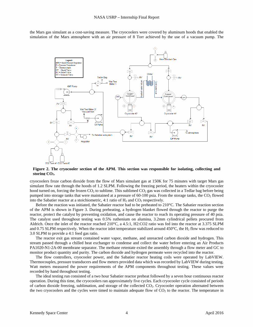
A. Atmosphere Processing Module Kennedy Space Center built and performs testing for the APM component of the MIP. The simplified equipment configuration diagram for the cryocooler section is shown in Figure 2. The carbon dioxide collection section of the APM contained two Cryotel GT cryocoolers operating at 150K. The cryocoolers functioned to isolate and capture CO2 from Mars gas. The Mars gas simulant was delivered to the cryocoolers from a k-bottle with the composition of 3.0% nitrogen (N2), 1.6% argon (Ar), and 95.4% carbon dioxide. During earlier tests, bottled CO2 was used instead of
Figure 1. The spent catalyst (left) was removed from the Sabatier reactor after it no longer performed as expected. It is much lighter in appearance and has many broken pellets compared to unused catalyst (right).
NASA USRP – Internship Final Report
Kennedy Space Center 4 April 2016
the Mars gas simulant as a cost-saving measure. The cryocoolers were covered by aluminum hoods that enabled the simulation of the Mars atmosphere with an air pressure of 8 Torr achieved by the use of a vacuum pump. The
cryocoolers froze carbon dioxide from the flow of Mars simulant gas at 150K for 75 minutes with target Mars gas simulant flow rate through the hoods of 1.2 SLPM. Following the freezing period, the heaters within the cryocooler hood turned on, forcing the frozen CO2 to sublime. This sublimed CO2 gas was collected in a Tedlar bag before being pumped into storage tanks that were maintained at a pressure of 60-100 psia. From the storage tanks, the CO2 flowed into the Sabatier reactor at a stoichiometric, 4:1 ratio of H2 and CO2 respectively.
Before the reaction was initiated, the Sabatier reactor had to be preheated to 210°C. The Sabatier reaction section of the APM is shown in Figure 3. During preheating, a hydrogen blanket flowed through the reactor to purge the reactor, protect the catalyst by preventing oxidation, and cause the reactor to reach its operating pressure of 40 psia. The catalyst used throughout testing was 0.5% ruthenium on alumina, 3.2mm cylindrical pellets procured from Aldrich. Once the inlet of the reactor reached 210°C, a 4.5:1, H2:CO2 ratio was fed into the reactor at 3.375 SLPM and 0.75 SLPM respectively. When the reactor inlet temperature stabilized around 450°C, the H2 flow was reduced to 3.0 SLPM to provide a 4:1 feed gas ratio.
The reactor exit gas stream contained water vapor, methane, and unreacted carbon dioxide and hydrogen. This stream passed through a chilled heat exchanger to condense and collect the water before entering an Air Products PA1020-N1-2A-00 membrane separator. The methane retentate exited the assembly through a flow meter and GC to monitor product quantity and purity. The carbon dioxide and hydrogen permeate were recycled into the reactor.
The flow controllers, cryocooler power, and the Sabatier reactor heating coils were operated by LabVIEW. Thermocouples, pressure transducers and flow meters provided data which was recorded by LabVIEW during testing. Watt meters measured the power requirements of the APM components throughout testing. These values were recorded by hand throughout testing.
The ideal testing run consisted of a two hour Sabatier reactor preheat followed by a seven hour continuous reactor operation. During this time, the cryocoolers ran approximately five cycles. Each cryocooler cycle consisted of periods of carbon dioxide freezing, sublimation, and storage of the collected CO2. Cryocooler operation alternated between the two cryocoolers and the cycles were timed to maintain adequate flow of CO2 to the reactor. The temperature in
Figure 2. The cryocooler section of the APM. This section was responsible for isolating, collecting and storing CO2.
NASA USRP – Internship Final Report
Kennedy Space Center 5 April 2016
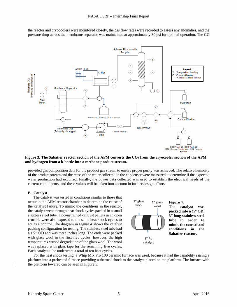
the reactor and cryocoolers were monitored closely, the gas flow rates were recorded to assess any anomalies, and the pressure drop across the membrane separator was maintained at approximately 30 psi for optimal operation. The GC
provided gas composition data for the product gas stream to ensure proper purity was achieved. The relative humidity of the product stream and the mass of the water collected in the condenser were measured to determine if the expected water production had occurred. Finally, the power data collected was used to establish the electrical needs of the current components, and these values will be taken into account in further design efforts.
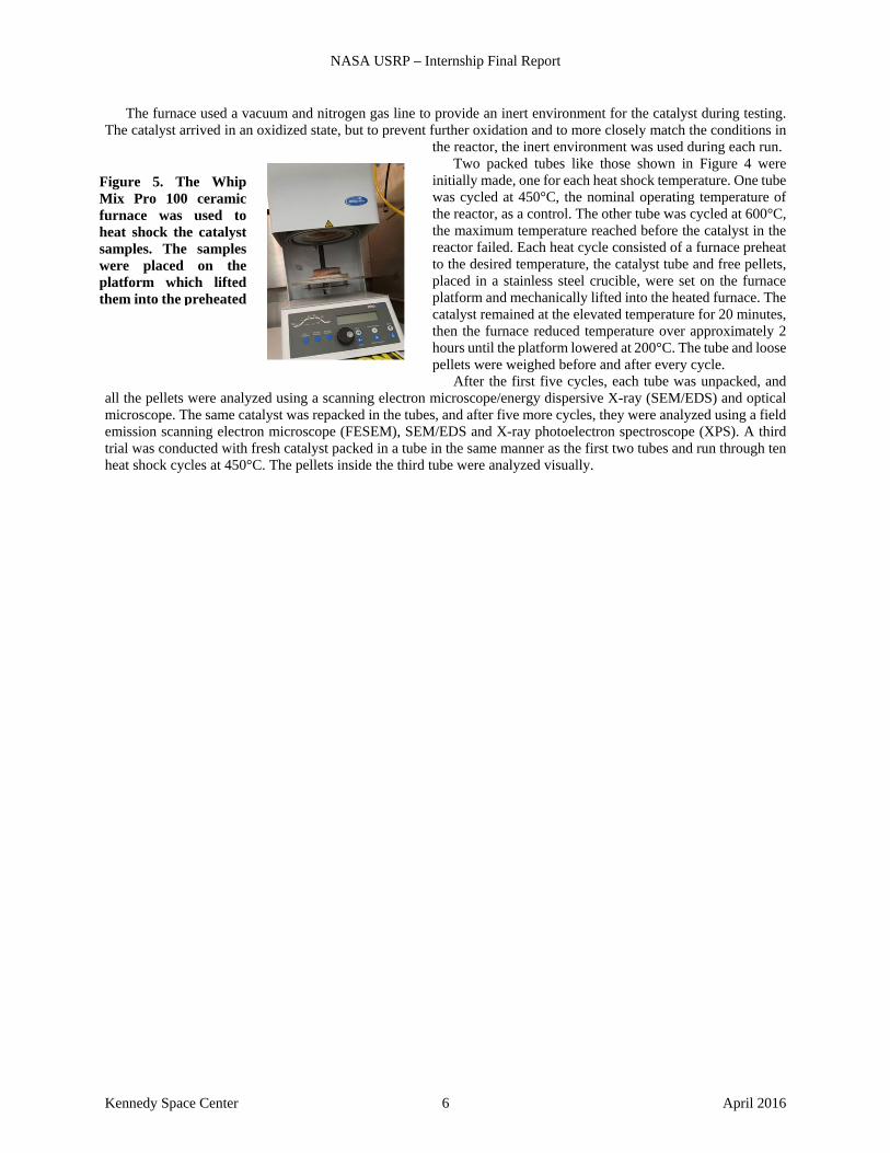
B. Catalyst The catalyst was tested in conditions similar to those that
occur in the APM reactor chamber to determine the cause of the catalyst failure. To mimic the conditions in the reactor, the catalyst went through heat shock cycles packed in a small stainless steel tube. Unconstrained catalyst pellets in an open crucible were also exposed to the same heat shock cycles to act as a control. The diagram in Figure 4 shows the catalyst packing configuration for testing. The stainless steel tube had a 1/2” OD and was three inches long. The ends were packed with glass wool in the first five cycles, however, the high temperatures caused degradation of the glass wool. The wool was replaced with glass tape for the remaining five cycles. Each catalyst tube underwent a total of ten heat cycles.
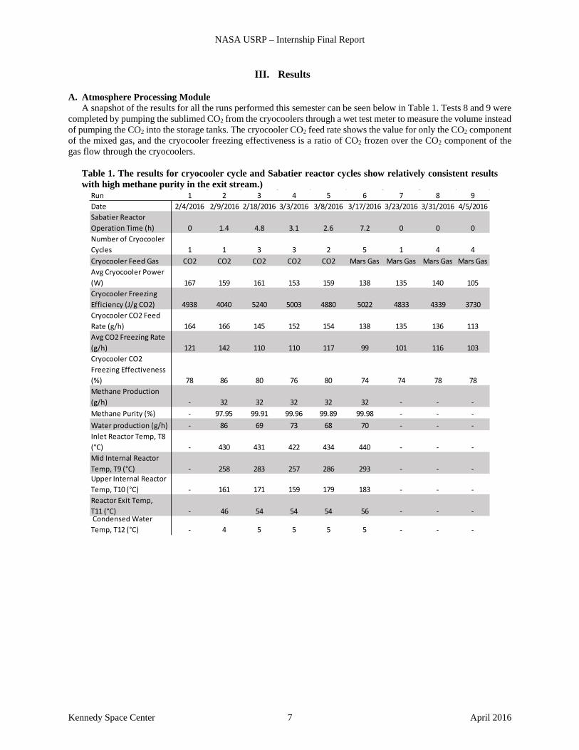
For the heat shock testing, a Whip Mix Pro 100 ceramic furnace was used, because it had the capability raising a platform into a preheated furnace providing a thermal shock to the catalyst placed on the platform. The furnace with the platform lowered can be seen in Figure 5.
Figure 3. The Sabatier reactor section of the APM converts the CO2 from the cryocooler section of the APM and hydrogen from a k-bottle into a methane product stream.
Figure 4. The catalyst was packed into a ½” OD, 3” long stainless steel tube in order to mimic the constricted conditions in the Sabatier reactor.
NASA USRP – Internship Final Report
Kennedy Space Center 6 April 2016
The furnace used a vacuum and nitrogen gas line to provide an inert environment for the catalyst during testing. The catalyst arrived in an oxidized state, but to prevent further oxidation and to more closely match the conditions in
the reactor, the inert environment was used during each run. Two packed tubes like those shown in Figure 4 were
initially made, one for each heat shock temperature. One tube was cycled at 450°C, the nominal operating temperature of the reactor, as a control. The other tube was cycled at 600°C, the maximum temperature reached before the catalyst in the reactor failed. Each heat cycle consisted of a furnace preheat to the desired temperature, the catalyst tube and free pellets, placed in a stainless steel crucible, were set on the furnace platform and mechanically lifted into the heated furnace. The catalyst remained at the elevated temperature for 20 minutes, then the furnace reduced temperature over approximately 2 hours until the platform lowered at 200°C. The tube and loose pellets were weighed before and after every cycle.
After the first five cycles, each tube was unpacked, and all the pellets were analyzed using a scanning electron microscope/energy dispersive X-ray (SEM/EDS) and optical microscope. The same catalyst was repacked in the tubes, and after five more cycles, they were analyzed using a field emission scanning electron microscope (FESEM), SEM/EDS and X-ray photoelectron spectroscope (XPS). A third trial was conducted with fresh catalyst packed in a tube in the same manner as the first two tubes and run through ten heat shock cycles at 450°C. The pellets inside the third tube were analyzed visually.
Figure 5. The Whip Mix Pro 100 ceramic furnace was used to heat shock the catalyst samples. The samples were placed on the platform which lifted them into the preheated
NASA USRP – Internship Final Report
Kennedy Space Center 7 April 2016
III. Results
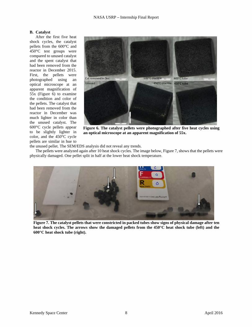
A. Atmosphere Processing Module A snapshot of the results for all the runs performed this semester can be seen below in Table 1. Tests 8 and 9 were
completed by pumping the sublimed CO2 from the cryocoolers through a wet test meter to measure the volume instead of pumping the CO2 into the storage tanks. The cryocooler CO2 feed rate shows the value for only the CO2 component of the mixed gas, and the cryocooler freezing effectiveness is a ratio of CO2 frozen over the CO2 component of the gas flow through the cryocoolers.
Table 1. The results for cryocooler cycle and Sabatier reactor cycles show relatively consistent results with high methane purity in the exit stream.)
Run 1 2 3 4 5 6 7 8 9Date 2/4/2016 2/9/2016 2/18/2016 3/3/2016 3/8/2016 3/17/2016 3/23/2016 3/31/2016 4/5/2016Sabatier Reactor Operation Time (h) 0 1.4 4.8 3.1 2.6 7.2 0 0 0Number of Cryocooler Cycles 1 1 3 3 2 5 1 4 4Cryocooler Feed Gas CO2 CO2 CO2 CO2 CO2 Mars Gas Mars Gas Mars Gas Mars GasAvg Cryocooler Power (W) 167 159 161 153 159 138 135 140 105Cryocooler Freezing Efficiency (J/g CO2) 4938 4040 5240 5003 4880 5022 4833 4339 3730Cryocooler CO2 Feed Rate (g/h) 164 166 145 152 154 138 135 136 113Avg CO2 Freezing Rate (g/h) 121 142 110 110 117 99 101 116 103Cryocooler CO2 Freezing Effectiveness (%) 78 86 80 76 80 74 74 78 78Methane Production (g/h) - 32 32 32 32 32 - - -Methane Purity (%) - 97.95 99.91 99.96 99.89 99.98 - - -Water production (g/h) - 86 69 73 68 70 - - -Inlet Reactor Temp, T8 (°C) - 430 431 422 434 440 - - -Mid Internal Reactor Temp, T9 (°C) - 258 283 257 286 293 - - -Upper Internal Reactor Temp, T10 (°C) - 161 171 159 179 183 - - -Reactor Exit Temp, T11 (°C) - 46 54 54 54 56 - - - Condensed Water Temp, T12 (°C) - 4 5 5 5 5 - - -
NASA USRP – Internship Final Report
Kennedy Space Center 8 April 2016
B. Catalyst After the first five heat
shock cycles, the catalyst pellets from the 600°C and 450°C test groups were compared to unused catalyst and the spent catalyst that had been removed from the reactor in December 2015. First, the pellets were photographed using an optical microscope at an apparent magnification of 55x (Figure 6) to examine the condition and color of the pellets. The catalyst that had been removed from the reactor in December was much lighter in color than the unused catalyst. The 600°C cycle pellets appear to be slightly lighter in color, and the 450°C cycle pellets are similar in hue to the unused pellet. The SEM/EDS analysis did not reveal any trends.
The pellets were analyzed again after 10 heat shock cycles. The image below, Figure 7, shows that the pellets were physically damaged. One pellet split in half at the lower heat shock temperature.
Figure 6. The catalyst pellets were photographed after five heat cycles using an optical microscope at an apparent magnification of 55x.
Figure 7. The catalyst pellets that were constricted in packed tubes show signs of physical damage after ten heat shock cycles. The arrows show the damaged pellets from the 450°C heat shock tube (left) and the 600°C heat shock tube (right).
NASA USRP – Internship Final Report
Kennedy Space Center 9 April 2016
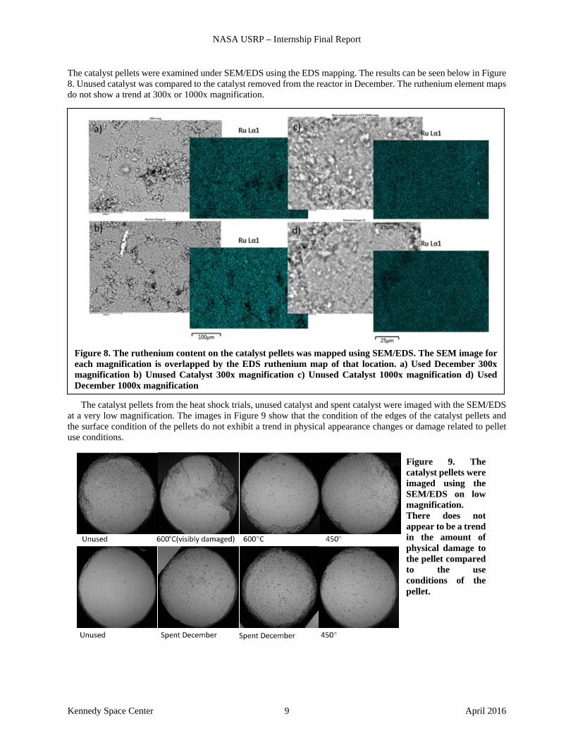
The catalyst pellets were examined under SEM/EDS using the EDS mapping. The results can be seen below in Figure 8. Unused catalyst was compared to the catalyst removed from the reactor in December. The ruthenium element maps do not show a trend at 300x or 1000x magnification.
The catalyst pellets from the heat shock trials, unused catalyst and spent catalyst were imaged with the SEM/EDS at a very low magnification. The images in Figure 9 show that the condition of the edges of the catalyst pellets and the surface condition of the pellets do not exhibit a trend in physical appearance changes or damage related to pellet use conditions.
Figure 8. The ruthenium content on the catalyst pellets was mapped using SEM/EDS. The SEM image for each magnification is overlapped by the EDS ruthenium map of that location. a) Used December 300x magnification b) Unused Catalyst 300x magnification c) Unused Catalyst 1000x magnification d) Used December 1000x magnification
Figure 9. The catalyst pellets were imaged using the SEM/EDS on low magnification. There does not appear to be a trend in the amount of physical damage to the pellet compared to the use conditions of the pellet.
NASA USRP – Internship Final Report
Kennedy Space Center 10 April 2016
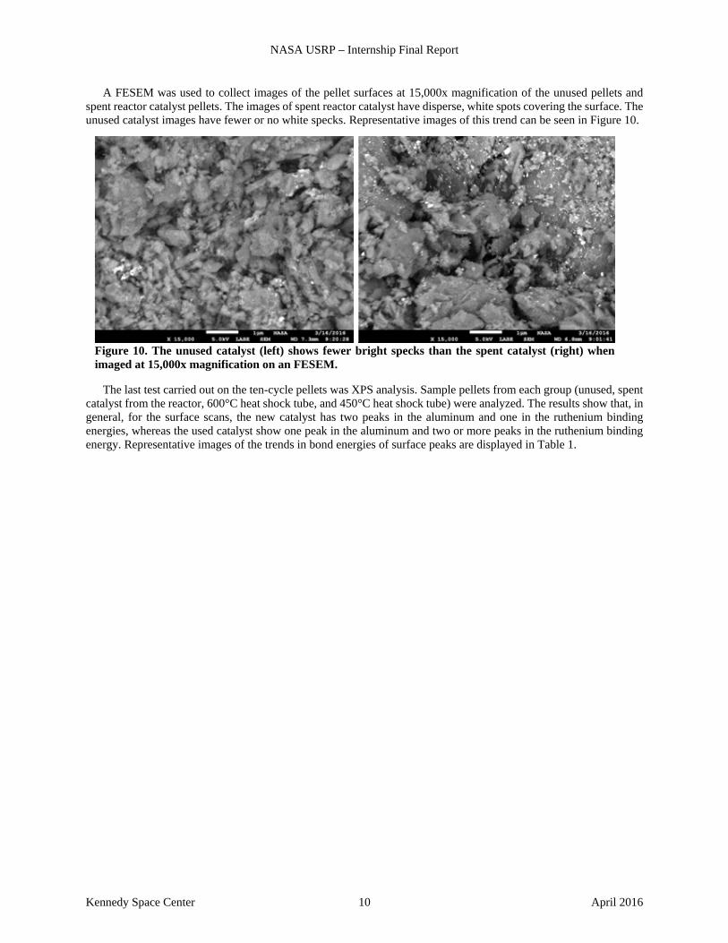
A FESEM was used to collect images of the pellet surfaces at 15,000x magnification of the unused pellets and spent reactor catalyst pellets. The images of spent reactor catalyst have disperse, white spots covering the surface. The unused catalyst images have fewer or no white specks. Representative images of this trend can be seen in Figure 10.
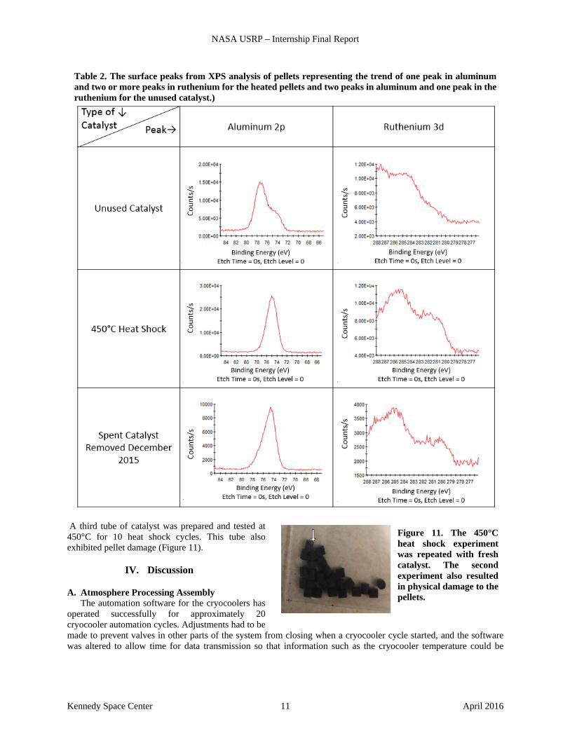
The last test carried out on the ten-cycle pellets was XPS analysis. Sample pellets from each group (unused, spent catalyst from the reactor, 600°C heat shock tube, and 450°C heat shock tube) were analyzed. The results show that, in general, for the surface scans, the new catalyst has two peaks in the aluminum and one in the ruthenium binding energies, whereas the used catalyst show one peak in the aluminum and two or more peaks in the ruthenium binding energy. Representative images of the trends in bond energies of surface peaks are displayed in Table 1.
Figure 10. The unused catalyst (left) shows fewer bright specks than the spent catalyst (right) when imaged at 15,000x magnification on an FESEM.
NASA USRP – Internship Final Report
Kennedy Space Center 11 April 2016
A third tube of catalyst was prepared and tested at 450°C for 10 heat shock cycles. This tube also exhibited pellet damage (Figure 11).
IV. Discussion
A. Atmosphere Processing Assembly The automation software for the cryocoolers has
operated successfully for approximately 20 cryocooler automation cycles. Adjustments had to be made to prevent valves in other parts of the system from closing when a cryocooler cycle started, and the software was altered to allow time for data transmission so that information such as the cryocooler temperature could be
Table 2. The surface peaks from XPS analysis of pellets representing the trend of one peak in aluminum and two or more peaks in ruthenium for the heated pellets and two peaks in aluminum and one peak in the ruthenium for the unused catalyst.)
Figure 11. The 450°C heat shock experiment was repeated with fresh catalyst. The second experiment also resulted in physical damage to the pellets.
NASA USRP – Internship Final Report
Kennedy Space Center 12 April 2016
monitored and used for the automation software. Also, the cryocooler power supply and communication system was rewired and the software improved to prevent arbitrary cryocooler function.
For many runs, the amount of water that should be produced given the amount of methane production exceeds the amount of water collected during the run. This disparity can be off by more than 11%. It was thought that the membrane separator may have been collecting water, so the membrane separator apparatus was weighed before and after Runs 2 and 3. The mass of the apparatus did not change, indicating that water was not collecting there. Other possible explanations could be that the relative humidity of the product stream varied from approximately 3% to 16% over time, or the orientation of the water condenser heat exchanger could be trapping water.
During testing, the water collected from the condenser located downstream of the reactor had a pH of 5.5. Previously, the water collected tested at a pH of 7. An increase in the amount of CO2 in the reactor effluent stream could be causing an increase in acidity in the condensed water. An increase in CO2 in the reactor effluent stream indicates the reaction is not reaching the same conversion as it was previously. Soon, a water cleanup module will be connected to the water collection system. Water with non-neutral pH may cause this equipment to malfunction.
When the hood from cryocooler #2 was removed in February, a fine layer of brown dust was observed over all interior surfaces. Analyses by SEM and XPS was inconclusive, but the main component of the dust was determined to be copper. It is important to determine origin of this dust and its production rate, because if the copper cold caps degrade over time, the flight equipment will need to be more robust or thicker to accommodate for the observed wear.
The heater damage caused by the vacuum tubing could be prevented by shortening the vacuum tube. However, earlier tests showed that the vacuum tube must be placed very close to the cold finger to encourage gas flow across and through the freezing surfaces. The cryocooler equipment was not altered other than the new heater installation.
During Mars gas flow, the pressure inside the cryocooler hoods increased throughout the run, starting at 8 Torr and reaching just over 11 Torr. Large changes in pressure have minimal effects on freezing temperature, so the 3 Torr change in pressure will likely have a negligible effect on the freezing temperature of each Mars gas species.
At Mars gas flow rate as low as 1.0 SLPM (Run 9), the CO2 freezing rate greatly exceeded the 88 g/h freezing rate required by the Sabatier reactor. This lower flow rate meets the system requirements and uses far less energy than the higher flow rates. However, during Sabatier operation at nominal cryocooler gas flow of 1.2 SLPM, the cryocoolers were unable to provide the carbon dioxide needed to maintain the storage tank pressure. The CO2 freezing rate calculated for Run 6, which fed the cryocooler CO2 to the storage tanks, and Run 8, which measured the amount of frozen CO2 using a wet test meter, show that Run 8 had a much higher freezing rate of 116 g/h versus the 99 g/h for Run 6. Both values are well above the goal CO2 capture rate of 88 g/h, yet the CO2 tanks had to be supplemented with facility CO2 during every lengthy Sabatier operation. The flow controllers providing gas to the cryocoolers and Sabatier reactor were calibrated multiple times throughout the testing period, so the reported flow rates should be relatively accurate.
Table 1 shows a great variation in performance among the runs. Each cryocooler performs with some variation between them and from cycle to cycle. One cause of variation could be ambient air temperature swings in the lab, which can vary more than 20 degrees Fahrenheit throughout the day, this temperature swing affects the temperature of the cryocooler housing and the feed gas. A great deal of variability in cryocooler performance has been observed on a cycle to cycle basis, but the average performance of the cryocoolers across multiple cycles is relatively consistent.
B. Catalyst During the heat shock trials, the pellets packed in the stainless steel tube showed signs of physical damage, but the
unconstricted pellets that were heated in the crucible did not show signs of physical damage. The packing procedure may have played a role in the pellet damage, but the majority of the observed physical damage is likely due to the constriction caused by the pellets expanding when heated and pressing into each other and the walls of the tube. Prior to the heat shock trials, it was believed that the damage to the catalyst pellets in the Sabatier reactor was caused by the 600°C temperature anomaly, however, cycling the pellets at 450°C, the nominal Sabatier reactor operating temperature, caused substantial physical damage.
The observed change in pellet color, turning from black to grey, occurred more rapidly in the catalyst cycled at 600°C. It is unknown if the grey color is indicative of catalyst degradation or failure, but the catalyst removed from the reactor were starkly lighter in hue than unused catalyst as seen in Figure 1.
The lower magnification SEM mapping does not show an apparent difference between the unused and spent catalyst, however the high magnification, FESEM images show a trend of an increase in the number of white specks in the spent catalyst. The white specks are believed to be ruthenium. The brightness of the spots indicates that it is an element much heavier than the oxygen and aluminum that make up the alumina support pellet. The brightness of these spots rules out silica from the glass wool packing material. Some EDS analysis and the test configuration indicate the specks are ruthenium and not copper from the cold heads. The visible white specks on the spent reactor catalyst could
NASA USRP – Internship Final Report
Kennedy Space Center 13 April 2016
be caused by ruthenium sintering and coalescing into clusters that are large enough for the FESEM to detect. Fewer visible ruthenium specks on the unused catalyst could indicate that the ruthenium is still very disperse across the surface of the pellet.
One of the potential sources of catalyst poisoning is the thermal paste used to mate the cryocooler cold finger with the copper cryocooler cap. The compound used, Céramique 2, is likely not a poison due to its chemical composition of: synthetic oil, aluminum oxide, boron nitride, and zinc oxide, which are not known to be ruthenium catalyst poisons. The thermal paste had to be reapplied when the heater was repaired in cryocooler #2 meaning that the previous application had dispersed from the cryocooler cold finger and passed through other components of the APM after it left the cryocooler. It was a small amount of product, but its effects on the other components are unknown.
The XPS results show that aluminum and ruthenium bond energy spectrums at the surface of the pellet are consistently different on the unused pellet compared to the pellets that had undergone heat shock. The spent pellets from the reactor and the 450°C and 600°C heat shock pellets showed very similar peak trends to each other. This indicates that the high temperatures experienced by the pellets or the rapid increase in temperature was the driving factor in the change and not other factors such as poisoning. Further analysis is underway.
V. Future Work and Recommendations
When the CO2 tank pressure neared or fell slightly below 60 psia, the Sabatier system would not function properly due to the pressure drop required for proper flow controller operation. To avoid these disruptions in flow to the Sabatier reactor, the CO2 tanks should be maintained at pressures between 65 psia and 100 psia.
The automation software currently opens the valves connecting the cryocooler hoods to the Tedlar bag two minutes after the end of CO2 collection. At the end of two minutes, the pressure in the hood is still quite low, so when the valves open, the vacuum is filled with the contents of the Tedlar bag, and possibly air if the bag is empty. The possibility of air and water vapor leaking into the system during this step could be mitigated by altering the software to open the valves after the cryocooler reaches the temperature of CO2 sublimation, approximately 190K. When the change is made, the sublimation period may take longer, because pulling in this CO2 and air increases the temperature in the hood very quickly, aiding in the rate of sublimation.
Cryocooler #1 should be opened to see if the dust found in cryocooler #2 is present. Further analysis should be done to find the composition of the dust, and if the dust is determined to be from the cryocooler caps, the cause of the dusting and rate of loss should be determined. This will ensure that the cryocoolers can sustain a sufficient CO2 freezing rate for long duration operation on Mars.
The results from the XPS analysis indicate a clear trend between the used and unused catalyst. Analysis is complicated by the fact that the carbon peak overlaps the ruthenium peaks [10]. Some literature is available on typical ruthenium on alumina binding energy peaks, but more work is needed to interpret the results.
If the alumina pellets that currently support the ruthenium catalyst in the packed bed cannot withstand the operating conditions, other options will need to be explored. A miniature reactor could be assembled for testing various catalysts at the upper and lower bounds of operating conditions. Various sized pellets and other support structures with heavier catalyst loads could be tested. A heavier catalyst load with a robust support structure has been successfully implemented by Hamilton Sundstrand for the Sabatier reactor currently in flight on the ISS. If the pellet damage and heat damage is caused by the heat shock experienced by the pellets, the gas flows rates to the reactor could be increased more slowly so that the temperature of the pellets ramps up more slowly and prevents the formation of hot spots.
The pH of the water collected from the water condenser should be measured again to confirm the previous finding of a pH of 5.5. If the water is more acidic than expected, the composition of the product stream should be checked to ensure that proper CO2 conversion is occurring.
The next step in testing for the APM is a virtual integration test across a network connecting the MIP components to each other from the centers that house them. The components of the Mars ISRU Pathfinder need to interface with each other successfully and perform in a synchronized manner so that the components providing materials needed for another component are performing as needed and communicating effectively.
During my internship, I exercised and honed some skills I had previously developed, while learning many new ones. I spent approximately one day per week operating and troubleshooting the APM. During this time, I learned more about LabVIEW and about experimental procedures and typical lab equipment such as flow meters, pumps, etc. I collected and analyzed the APM data and recorded information about each run for future use, encouraging me to think critically about which data were important and practice proper documentation techniques. I also learned how to calibrate the GC and make calibration gas mixtures. For catalyst testing, I developed an experimental plan, carried out
NASA USRP – Internship Final Report
Kennedy Space Center 14 April 2016
testing, and analyzed the results to develop conclusions. In order to analyze the catalyst, I learned to operate an optical microscope, an SEM/EDS and an FESEM. I also received instruction on XPS operation and result analysis. By writing this paper, I further developed my technical and report-writing skills. All of these accomplishments and practices will be very useful in the future as I enter graduate school in the fall and continue to conduct research throughout my career. I also very much enjoyed my time at Kennedy performing such interesting work with a very supportive group of people.
VI. Conclusion The cryocooler automation software functions well and is ready for Mars ISRU Pathfinder integration testing. The calculations and measurements of CO2 freezing rates indicate they surpass the rate needed to maintain the Sabatier reaction, but during long-duration testing, the flow was insufficient and had to be supplemented with facility CO2. More testing is needed to determine why the cryocooler cycles are not maintaining the flow needed for the Sabatier reactor. Other minor issues like the water collection disparity, the condensed water pH, and the copper cryocooler cap dusting will need to be considered as the Atmosphere Processing Module proceeds through the flight readiness levels.
The catalyst pellet damage appears to be caused by elevated temperatures or heat shock and not poisoning or interference by the alumina support structure. The stainless steel tubes and furnace could be used to test the effectiveness of ramping the temperature more slowly to the reaction temperature, and simple changes to the procedure could be made to insure the reactor temperature does not increase too rapidly. A miniature reactor could be constructed for testing other catalysts, catalyst loading weights, or catalyst supports if the current conditions will not meet flight requirements.
VII. Acknowledgments I would like to thank everyone I have had the pleasure of working with during my internship. I would not have been
able to accomplish everything I did without the knowledge, instruction, and time that had been so generously shared with me. I am especially grateful to have worked with my mentor, Annie Meier; her dedication, intelligence, and perseverance are truly an inspiration. Special thanks to Dr. Paul Hintze for all the knowledge he patiently shared with me. I would also like to thank Dr. Anthony Muscatello, Jon Bayliss, Phil Howard, Bob Athman, and Macy Mullen for all of their assistance and support.
NASA USRP – Internship Final Report
Kennedy Space Center 15 April 2016
VIII. References
[1] M. A. Intervartolo III, G. B. Sanders, L. Oryshchyn, K. Lee, H. Vaccaro, E. Santiago-Maldonado and A. C.
Muscatello, "Prototype Development of an Integrated Mars," Journal of Aerospace Engineeing, no. 26, pp. 57-66, 2013.
[2] A. Muscatello, R. Devor and J. Captain, "Atmospheric Processing Module for Mars Propellant Production," in ASCE Earth an dSpace Conference, St. Louis, 2014.
[3] D. Schlereth and O. Hinrichsen, "A fixed-bed reactor modeling study on the methanation of CO2," Chemical Engineering Research and Design, no. 92, pp. 702-712, 2014.
[4] P. J. Lunde and F. L. Kester, "Kinetics of Carbon-Dioxide Methanation on a Ruthenium Catalyst," Papers of the American Chemical Society, vol. 164, pp. 11-27, 1972.
[5] C. Junaedi, K. Hawley, D. Walsh, S. Roychoudhury, M. B. Abney and J. L. Perry, "Compact and Lightweight Sabatier Reactor for Carbon Dioxide Reduction," in International Converence on Environmental Systems, Portland, 2011.
[6] P. E. Hintze, A. J. Caraccio, J. A. Bayliss and A. C. Muscatello, "Mars Atmospheric In Situ Resource Utilization - Atmospheric Processing Module FY15," 2015.
[7] D. J. Samplatsky, K. Grohs, M. Edeen, J. Crusan and R. Burkey, "Development and Integration of the Flight Sabatier Assembly on the ISS," in International Confrence on Environmental Systems, Portland, 2011.
[8] C. H. Bartholomew, "Mechanisms of catalyst deactivation," Applied Catalysis, no. 212, pp. 17-60, 2001. [9] J. Okal and L. Kepinski, "Sintering of Colloidal Ru/gamma-Al2O3 Catalyst in Hydrogen," Catalysis Letters,
vol. 128, no. 3, pp. 331-336, 2009. [10] V. Mazzieri, F. Coloma-Pascual, A. Arcoya, P. C. L'Argentiere and N. S. Figoli, "XPS, FTIR and TPR
characterization of Ru/Al2O3 catalysts," Applied Surface Science, vol. 210, no. 3-4, pp. 222-230, 2003.