atmospheric vapor extraction device
TRANSCRIPT

Atmospheric Vapor Extraction Device
By
Adnan Alhashim, Nathan Allred, Essa Alowis Travis Butterly, Andy McPhail, Nate Ogbasellasie
Final Report
Submitted towards partial fulfillment of the requirements for Mechanical Engineering Design II – Spring 2015
Department of Mechanical Engineering Northern Arizona University
Flagstaff, AZ 86011

Table of Contents
1. Introduction 1
2. Problem Statement 1
3. Concept 3
4. Cooling Calculations 6
5. Electronic Devices 7
6. Lid Assembly 8
7. Design 10
8. Manufacturing 11
9. Result 14
10. Bill of Materials 15
11. Future Modifications 16
12. Conclusion 16
13. References 17
1

1. Introduction
The team wishes to put into practice an idea proposed by Chris Allender who is a biological
sciences graduate student at NAU. Chris wishes to build a device that will help in the study of
vapor extraction from the atmosphere. A constant supply of fresh water, coupled with an ever
increasing human population has resulted an unprecedented fresh water shortage among
developing nations as well as developed nations. Approximately two point five percent of the
earth’s water supplies are freshwater (National Geographic 2015). While approximately one
percent of these freshwater is easily accessible, the remaining one half percent remains an
untapped potential which contributes to the global clean water crisis.
Over extraction of freshwater from the world’s reserves has resulted in unprecedented constraints
on the supply of fresh water. Despite the numerous advances in the technologies that signify our
modern world, such as desalination plants, the overall constraints in the freshwater supply is still
a recurring issue among nations. Couple this with nonconservative habits that are common for
most households, institutions, and business organizations, the need a for new methods of mining
freshwater. As such, innovative techniques like vapor extraction possesses the ability to
counteract some of the rising needs for water
2. Problem Statement
The client, Mr. Christopher J Allender, is looking for a device that is capable of extracting water
from the atmosphere. Mr. Allender would like the device to collect data in order to find the
optimal condition for which a maximum amount of water can be extracted. Though water vapor
extraction devices do exist, there has not been enough research to find the optimal conditions.
This project will serve as a teaching tool for future devices, and will possibly be used to aid
communities that lack a potable water supply. The team’s goal is to create a working
2

atmospheric vapor extraction device that will be tested in different conditions, including:
pressure, temperature, elevation, humidity, etc.
The frame and lid have been completed and only the electronics remain unfinished. All of the
necessary components have already been purchased and are nearly wired in. The largest task left
is coding the electronics to operate properly.
3. Concept
The team identified three main functions of the device as shown in Figure 1. First, it needs to
have a power source; second, it needs to have a condensing process; and lastly, it must have
sensing equipment to detect and log the ambient weather conditions.
Figure 1 The Functional Diagram
The condensing process cools the air by dissipating the heat. Many refrigeration devices are
available on the market to do this, we chose to use koolatron 12 volt cooler which can cool down
up to 22oC below the ambient temperature.
3

Condensation results when air is cooled to its dew point temperature for its current pressure and
relative humidity. Considering the average annual temperatures, elevation, and relative humidity
of Flagstaff, the team estimates that the dew point temperature of the ambient air can be reached
by cooling the air by 15 or fewer degrees fahrenheit.
The koolatron is expected to perform about three times as well as required. Because the air
inside the cooler can be so cold, it allowed the team to design a continuous air system where
ambient air is passed through the system and cools enough to condense out most of its water
before leaving. To cool the ambient air, they made use of an aluminum heat exchanger that is
cooled by air recirculated in the koolatron. Water was allowed to collect at the bottom of the
cooler before being pumped out. The intended design is shown in Figure 2.
Figure 2 Design of Heat Exchanger Assembly
4

4. Cooling Calculations
The following section outlines the calculations for the temperature at which the water vapor in
the air will precipitate out as dew. The calculations were done using the Magnus Formula which
is illustrated in Figure 3. Temperature and relative humidity of the air are necessary. For these
values, it was assumed that the average annual temperature of Flagstaff, Arizona was about 16oC
and that the average annual relative humidity was about 53%. These values indicate that the air
must be cooled to near 6.43oC in order to extract the air. Therefore, the team required a cooler
that was capable of reducing the ambient air temperature by approx. 10oC. The selected
koolatron cooler is rated at over double (22oC) the required amount.
Figure 3 Diagram of the Magnus Formula to Estimate Dew Point Temperature
5

5. Electronic Devices
The Arduino runs ons an opensource platform capable of reading inputs, and returning an
output. For the Atmospheric Vapor Extraction Device, the Arduino is used to control the
following components: DHT11, Fans, Peristaltic Liquid Pump, and Liquid Level Sensor. The
DHT11 is a humidity/ temperature sensor that is capable of reading data through Arduino. For
this project 2 DHT11 sensors are used, one for the ambient air conditions and one for the
exhaust. This allows the user to determine the change in humidity before and after the air goes
through the device. Since this project requires a form of data storage, and SD card module is
used. The SD module utilizes a 2GB SD card, which can be read through a computer.
Furthermore, since the Arduino does not have an internal clock, a Real Time Clock module
(RTC) is also required to establish a time and date. With the RTC, the collected data can be
correlated with a time and day.
The fans used in this project are 12V DC PC fans in series. The Functional Diagram (Figure 1)
is used to portray this process, where the import air can be attributed to the inlet fan and export
air can be attributed to the exhaust fan. Depending on the humidity, the fan will either turn
on/off. Additionally, if the fan is on, its speed will be dependent on the humidity. For instance,
if the humidity is under 20%, the fans will turn off; on the other hand if the humidity is above
20% the fan will turn on. As the humidity increases above 20%, the fan will decrease in speed,
in order to push less air through the system. This will give the system enough time to cool the
moister air in an efficient manner.
The peristaltic liquid pump and liquid level sensor are used to measure the amount of water
collected on a daily basis. With the RTC, the pump can be set to turn on once a day. The pump
begins by pumping water into a pipe where the liquid level sensor is housed. The liquid level
sensor reads the height, and with the known pipe diameter the volume of water can be
determined. The water is then pumped out of the pipe and into a reservoir. Due to the liquid
6
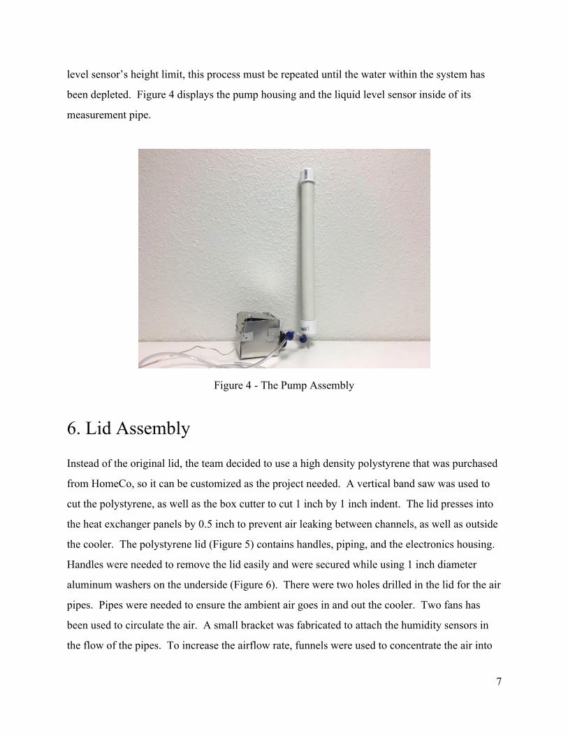
level sensor’s height limit, this process must be repeated until the water within the system has
been depleted. Figure 4 displays the pump housing and the liquid level sensor inside of its
measurement pipe.
Figure 4 The Pump Assembly
6. Lid Assembly
Instead of the original lid, the team decided to use a high density polystyrene that was purchased
from HomeCo, so it can be customized as the project needed. A vertical band saw was used to
cut the polystyrene, as well as the box cutter to cut 1 inch by 1 inch indent. The lid presses into
the heat exchanger panels by 0.5 inch to prevent air leaking between channels, as well as outside
the cooler. The polystyrene lid (Figure 5) contains handles, piping, and the electronics housing.
Handles were needed to remove the lid easily and were secured while using 1 inch diameter
aluminum washers on the underside (Figure 6). There were two holes drilled in the lid for the air
pipes. Pipes were needed to ensure the ambient air goes in and out the cooler. Two fans has
been used to circulate the air. A small bracket was fabricated to attach the humidity sensors in
the flow of the pipes. To increase the airflow rate, funnels were used to concentrate the air into
7
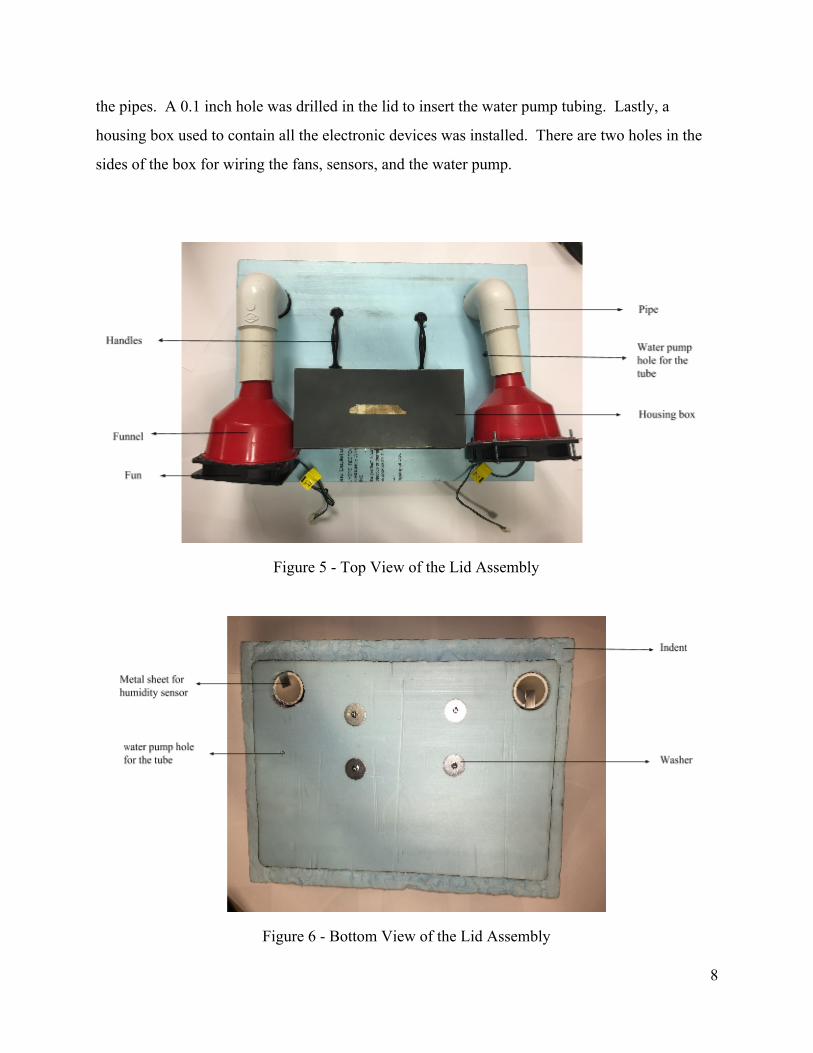
the pipes. A 0.1 inch hole was drilled in the lid to insert the water pump tubing. Lastly, a
housing box used to contain all the electronic devices was installed. There are two holes in the
sides of the box for wiring the fans, sensors, and the water pump.
Figure 5 Top View of the Lid Assembly
Figure 6 Bottom View of the Lid Assembly
8

7. Design
Three coolers were taken into consideration. The first option, the Igloo 40Quart, is a cooler to
store food and beverages of maximum 40 quarts. It was rejected because there were negative
reviews published about the product. The second option, the Dometic 15quart, is a cooling
facility that can be used at picnics, dorms etc. It was rejected due to its capacity issues as it is the
smallest in size. Lastly, the Koolatron 52 Quart was chosen because it was the best product to
fit the needs of the team.
The Koolatron cooler was chosen because of several features that satisfy the design criteria. The
appliance is capable of cooling 40 degrees Fahrenheit below the surroundings temperature. It is
light in weight and weighs about 17.4 pounds. The appliance has good size for a portable
refrigerator measuring 20 x 15.5 x 20 inches. It has a 12V outlet fitted with 120V AC adapter.
The traditional lid will be replaced by a customized polystyrene foam lid 2 inches thick. The
system will use the concept of ambient air cycle. The lid will have a piping system. The input
pipe will ensure ambient air input and the output pipe will release the dry air outside. On the
surface of the lid, fans will be introduced to circulate the air.
There will be a combination of fans that will be on under the lid. The operation of the fans will
depend on atmospheric conditions. The speed of the fan will be controlled and adjusted by an
arduino, a microcontroller, and an air sensor. The maximum level of air flow to be maintained by
the device will be 57.67 CFM. The fan speed will be around 1500 revolutions per minute (RPM)
with a upper and lower bound of 10%. The fans will be connected to the funnel which in turn
will be linked to tube assembly.
9

8. Manufacturing
In order to manufacture the cooling channels 22gage aluminum sheet metal was purchased from
Boyer Metal Co in Flagstaff, AZ. The team decided aluminum was the best choice to make the
channels because of its low weight, resistance to corrosion, affordability, and flexibility. Two
plate templates were made in order to make the cooling assembly. One template was made for
plates separating the cool air chambers from the ambient air chambers. Another template was
made for plates going between the first plates. The function of these pieces was to redirect the
air back and forth so that the ambient air has more time and cold aluminum surfaces to come in
contact with thus causing condensation The team used a large piece of paper to trace the outline
of the inside of the cooler. This method proved to make a plate that had a snug fit. A picture of
the plate can be seen below in Figure 7.
Figure 7 Heat Exchanger Assembly
10

The tools used to cut the plate to size were tin snips and electric metal shears. The electric shears
were used to cut the rough outline of the plate then fine tuned with the tin snips. After one good
metal plate was made seven reproductions were created. The plate inserts were intended to
redirect the air and separated the cooling chambers. In order to connect the rectangular inserts to
the plates the team created four notches on the outside of the rectangular inserts. Using a
Dremel, slots were machined into the plates for the notches to slide into and then bent to secure
them. A picture of the inserts before being installed can be seen below in Figure 8.
Figure 8 Templates of Inserts in Air Chambers
To circulate the cool air being produced from the cooler, a 2 inch stainless steel pipe was
purchased from Boyer Metal Co. The pipe was then machined to size using a horizontal band
saw. Using a Manual Mill ¼ inch holes were drilled into the pipe. Each set of holes is 2 inches
apart and has 4 holes separated equally around the circumference of the pipe. The holes in the
11
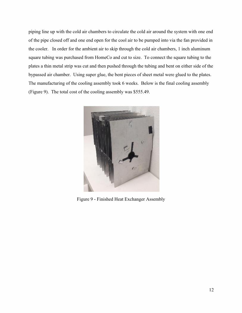
piping line up with the cold air chambers to circulate the cold air around the system with one end
of the pipe closed off and one end open for the cool air to be pumped into via the fan provided in
the cooler. In order for the ambient air to skip through the cold air chambers, 1 inch aluminum
square tubing was purchased from HomeCo and cut to size. To connect the square tubing to the
plates a thin metal strip was cut and then pushed through the tubing and bent on either side of the
bypassed air chamber. Using super glue, the bent pieces of sheet metal were glued to the plates.
The manufacturing of the cooling assembly took 6 weeks. Below is the final cooling assembly
(Figure 9). The total cost of the cooling assembly was $555.49.
Figure 9 Finished Heat Exchanger Assembly
12
9. Results
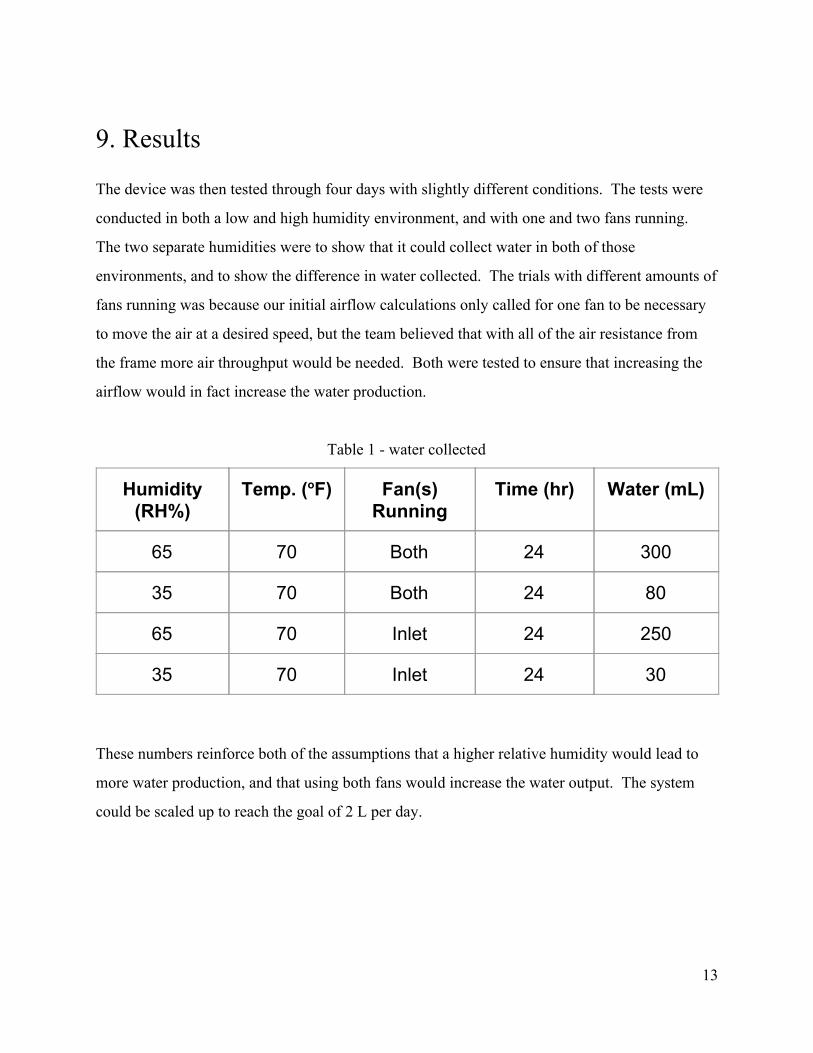
The device was then tested through four days with slightly different conditions. The tests were
conducted in both a low and high humidity environment, and with one and two fans running.
The two separate humidities were to show that it could collect water in both of those
environments, and to show the difference in water collected. The trials with different amounts of
fans running was because our initial airflow calculations only called for one fan to be necessary
to move the air at a desired speed, but the team believed that with all of the air resistance from
the frame more air throughput would be needed. Both were tested to ensure that increasing the
airflow would in fact increase the water production.
Table 1 water collected
Humidity (RH%)
Temp. (oF) Fan(s) Running
Time (hr) Water (mL)
65 70 Both 24 300
35 70 Both 24 80
65 70 Inlet 24 250
35 70 Inlet 24 30
These numbers reinforce both of the assumptions that a higher relative humidity would lead to
more water production, and that using both fans would increase the water output. The system
could be scaled up to reach the goal of 2 L per day.
13

10. Bill of Materials
Besides the main components, the team decided to purchase aluminum sheets, fans, a styrofoam
insulating lid, and pipes. The aluminum sheet was used in the manufacturing of the cooling
chambers, the styrofoam lid was used as an insulated lid in which holes can be drilled through.
The inlet and outlet were installed on the styrofoam lid. The fans were placed near the inlet and
outlet, in order to maintain airflow.
The team purchased the aluminum sheets, styrofoam lid, and pipes from Home Depot due to its
convenience and low price. Since computer fans proved to be sufficient, we purchased a 3pack
on amazon for $11. For this project no additional labor was considered because it was all done
in house. The final Bill of Materials is shown below in Table 2.
Table 2 Bill of Materials
Parts Price
Portable Cooler $169.00
Metal and Tools $105.00
Lid Assembly $88.00
Electronics $193.49
Total $555.49
14

11.Future Modifications
To better improve the performance of the device, the team would first aim to increase the flow of
the ambient air by improving the fan power. This would increase the amount of water in the
system by providing a greater supply of higher relative humidity air. This is the primary addition
that would improve water collection. In addition to increasing the fan power, the team would
also look into sealing the edges of the heat exchanger to reduce the loss in flow due to
unnecessary mixing. Furthermore, with enough airflow, the heat exchanger could possess more
plates to increase surface area and allow more heat transfer. Lastly, the cooler could be scaled
up into a larger (but less portable) device, such as a stand alone freezer. This would allow for
colder temperatures to take the relative humidity of the outlet air lower, as well as provide room
for a much larger heat exchanger and more powerful fans.
12. Conclusion
The prototype was expected to take measurement of the ambient air, to cool that air to its dew
point temperature, and to condense water out of it using an air to air heat exchanger cooled by a
koolatron portable cooler. Special considerations were taken to preserve the insulating
properties of the cooler by replacing the lid with a polystyrene foam board which allowed easy
modifications such as installation of airflow pipings and water tubing. The microcontroller was
installed with sensors to monitor and regulate the amount of air and water passing through the
system. The prototype remained well under budget. The team will move forward by finishing
the coding and beginning data collection. With experimental data, they will optimize the system
for maximum liquid water output.
15

13. References
[1] Clean Water Crisis, Water Crisis Facts, “Water Crisis Resources National Geographic.”
National Geographic. Web. 21 Sept. 2015.
[2] E. Schiff (2008, Jan 4). DewpointRH mk.svg [Online]. Available: http://www.wikipedia.com
[3] News, A. Achrnews. “The Basic Refrigeration Cycle.” Achrnews. A, 30 June 2003. Web. 09
Oct. 2015.
[4] Boelman, E.C., B.B. Saha, and Takao Kashiwagi. “Experimental Investigation of a Silica
GelWater Adsorption Refrigeration Cycle The Influence of Operating Conditions on Cooling
Output and COP.” United States: American Society of Heating, Refrigerating and
AirConditioning Engineers, Inc., Atlanta, GA (United States), 1995. Print.
[5] "Electric thermometer by using DHT11 sensor module." Geeetech. N.p., n.d. Web. 23 Oct.
2015.
[6] Handbook for Resistance Spot Welding. 335D ed. Vol. 003. Appleton: Miller Electric Mfg.,
2012. Print.
[7] Amazon.com,. 'Amazon.Com: Online Shopping For Electronics, Apparel, Computers,
Books, DVDs & More'. N.p., 2015. Web. 12 Dec. 2015.
[8] Homedepot.com. 'Home Improvement Made Easy With New Lower Prices'. N.p., 2015.
Web. 12 Dec. 2015.
[9] RadioShack,. 'Radioshack'. N.p., 2015. Web. 12 Dec. 2015.
16