atomic and electronic structures of single-layer fese on...
TRANSCRIPT
RAPID COMMUNICATIONS
PHYSICAL REVIEW B 87, 220503(R) (2013)
Atomic and electronic structures of single-layer FeSe on SrTiO3(001): The role of oxygen deficiency
Junhyeok Bang,1 Zhi Li,2 Y. Y. Sun,1,* Amit Samanta,3 Y. Y. Zhang,1 Wenhao Zhang,4 Lili Wang,2 X. Chen,4
Xucun Ma,2 Q.-K. Xue,2,4,† and S. B. Zhang1,‡1Department of Physics, Applied Physics and Astronomy, Rensselaer Polytechnic Institute, Troy, New York 12180, USA
2Institute of Physics, The Chinese Academy of Sciences, Beijing 100190, China3Program in Applied and Computational Mathematics, Princeton University, Princeton, New Jersey 08544, USA
4Department of Physics, Tsinghua University, Beijing 100084, China(Received 4 January 2013; revised manuscript received 28 May 2013; published 6 June 2013)
Using first-principles calculation, we propose an interface structure for single triple-layer FeSe on theSrTiO3(001) surface, a high-Tc superconductor found recently. The key component of this structure is theoxygen deficiency on the top layer of the SrTiO3 substrate, as a result of Se etching used in preparing the high-Tc
samples. The O vacancies strongly bind the FeSe triple layer to the substrate giving rise to a (2 × 1) reconstruction,as observed by scanning tunneling microscopy. The enhanced binding correlates to the significant increase of Tc
observed in experiment. The O vacancies also serve as the source of electron doping, which modifies the Fermisurface of the first FeSe layer by filling the hole pocket near the center of the surface Brillouin zone, as suggestedfrom angle-resolved photoemission spectroscopy measurement.
DOI: 10.1103/PhysRevB.87.220503 PACS number(s): 74.78.−w, 68.55.Ln, 73.61.−r, 74.62.Dh
High transition temperature (Tc) superconductors weremainly cuprate-based materials.1 The recent discovery of iron-based superconductors2–9 has significantly enriched the familyof high-Tc superconductors. Probably of greater importanceis that the new iron-based superconductors could serve asa critical test bed for the theories that have been proposedto understand the mechanism of high-Tc superconductivity.Currently, pnictides hold the highest Tc achieved in iron-basedsuperconductors.8,9 Tc above liquid nitrogen temperature(77 K), however, has not been realized yet. A recent report ofTc around 77 K from scanning tunneling microscopy (STM)measurement10 on an iron chalcogenide—namely, FeSe—isparticularly interesting and calls for a thorough understanding.
The findings in Ref. 10 are important from at least twoaspects. First, the high Tc was observed on one-unit-cell-thick(1 UC) FeSe deposited on the SrTiO3(001) surface. So,this system represents the simplest building blocks of mosthigh-Tc superconductors, which are usually layered materials.1
Understanding the mechanism in such a simple system couldprovide important insights to the understanding of morecomplex high-Tc superconductors. Second, bulk FeSe has a Tc
of only about 8 K.7 The drastic increase in Tc after depositionon the SrTiO3 substrate indicates a critical role of the strongcoupling between the 1 UC FeSe and the substrate. In contrast,the deposited FeSe layers thicker than 1 UC do not exhibit highTc.10 It is worthwhile to note that such strong coupling couldexist in most layered superconductors and be an importantcomponent of the mechanism for high-Tc superconductivity.
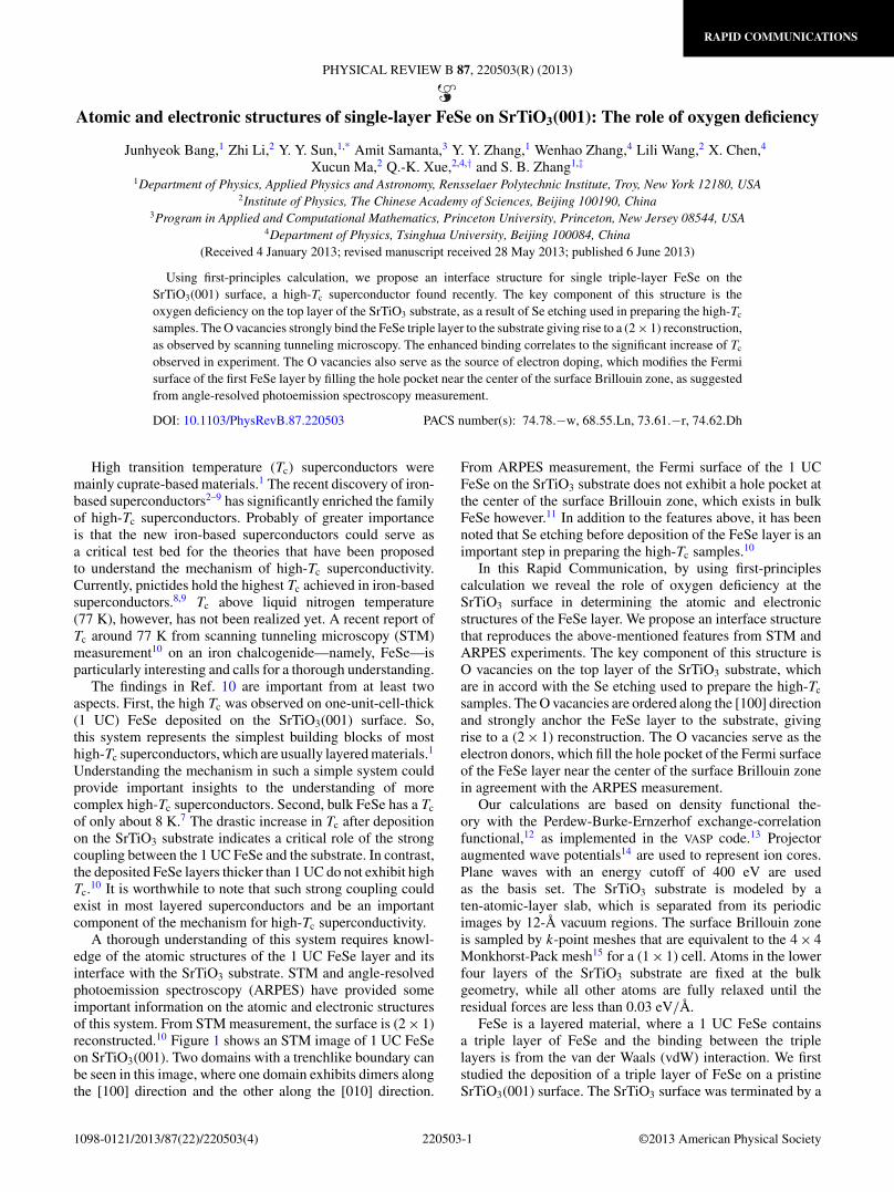
A thorough understanding of this system requires knowl-edge of the atomic structures of the 1 UC FeSe layer and itsinterface with the SrTiO3 substrate. STM and angle-resolvedphotoemission spectroscopy (ARPES) have provided someimportant information on the atomic and electronic structuresof this system. From STM measurement, the surface is (2 × 1)reconstructed.10 Figure 1 shows an STM image of 1 UC FeSeon SrTiO3(001). Two domains with a trenchlike boundary canbe seen in this image, where one domain exhibits dimers alongthe [100] direction and the other along the [010] direction.
From ARPES measurement, the Fermi surface of the 1 UCFeSe on the SrTiO3 substrate does not exhibit a hole pocket atthe center of the surface Brillouin zone, which exists in bulkFeSe however.11 In addition to the features above, it has beennoted that Se etching before deposition of the FeSe layer is animportant step in preparing the high-Tc samples.10
In this Rapid Communication, by using first-principlescalculation we reveal the role of oxygen deficiency at theSrTiO3 surface in determining the atomic and electronicstructures of the FeSe layer. We propose an interface structurethat reproduces the above-mentioned features from STM andARPES experiments. The key component of this structure isO vacancies on the top layer of the SrTiO3 substrate, whichare in accord with the Se etching used to prepare the high-Tc
samples. The O vacancies are ordered along the [100] directionand strongly anchor the FeSe layer to the substrate, givingrise to a (2 × 1) reconstruction. The O vacancies serve as theelectron donors, which fill the hole pocket of the Fermi surfaceof the FeSe layer near the center of the surface Brillouin zonein agreement with the ARPES measurement.
Our calculations are based on density functional the-ory with the Perdew-Burke-Ernzerhof exchange-correlationfunctional,12 as implemented in the VASP code.13 Projectoraugmented wave potentials14 are used to represent ion cores.Plane waves with an energy cutoff of 400 eV are usedas the basis set. The SrTiO3 substrate is modeled by aten-atomic-layer slab, which is separated from its periodicimages by 12-A vacuum regions. The surface Brillouin zoneis sampled by k-point meshes that are equivalent to the 4 × 4Monkhorst-Pack mesh15 for a (1 × 1) cell. Atoms in the lowerfour layers of the SrTiO3 substrate are fixed at the bulkgeometry, while all other atoms are fully relaxed until theresidual forces are less than 0.03 eV/A.
FeSe is a layered material, where a 1 UC FeSe containsa triple layer of FeSe and the binding between the triplelayers is from the van der Waals (vdW) interaction. We firststudied the deposition of a triple layer of FeSe on a pristineSrTiO3(001) surface. The SrTiO3 surface was terminated by a
220503-11098-0121/2013/87(22)/220503(4) ©2013 American Physical Society
RAPID COMMUNICATIONS
JUNHYEOK BANG et al. PHYSICAL REVIEW B 87, 220503(R) (2013)
FIG. 1. (Color online) STM image of 1 UC FeSe on theSrTiO3(001) surface. Two domains are shown, which are separatedby a trenchlike structure. One domain exhibits (2 × 1) reconstructionalong the [100] direction, while the other one along the [010]direction. The scanning area is 12.8 × 12.8 nm2. The bias voltageand tunneling current for obtaining this image are 0.6 V and 46.5 pA,respectively.
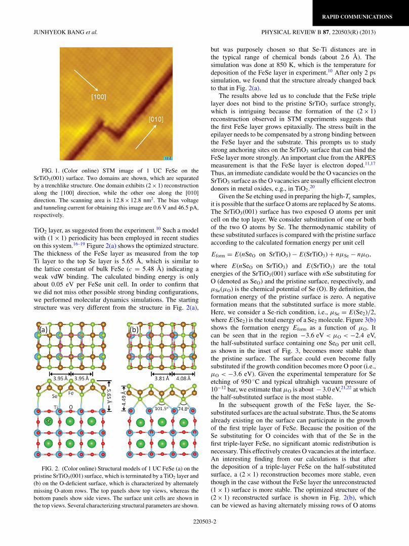
TiO2 layer, as suggested from the experiment.10 Such a modelwith (1 × 1) periodicity has been employed in recent studieson this system.16–19 Figure 2(a) shows the optimized structure.The thickness of the FeSe layer as measured from the topTi layer to the top Se layer is 5.65 A, which is similar tothe lattice constant of bulk FeSe (c = 5.48 A) indicating aweak vdW binding. The calculated binding energy is onlyabout 0.05 eV per FeSe unit cell. In order to confirm thatwe did not miss other possible strong binding configurations,we performed molecular dynamics simulations. The startingstructure was very different from the structure in Fig. 2(a),
FIG. 2. (Color online) Structural models of 1 UC FeSe (a) on thepristine SrTiO3(001) surface, which is terminated by a TiO2 layer and(b) on the O-deficient surface, which is characterized by alternatelymissing O-atom rows. The top panels show top views, whereas thebottom panels show side views. The surface unit cells are shown inthe top views. Several characterizing structural parameters are shown.
but was purposely chosen so that Se-Ti distances are inthe typical range of chemical bonds (about 2.6 A). Thesimulation was done at 850 K, which is the temperature fordeposition of the FeSe layer in experiment.10 After only 2 pssimulation, we found that the structure already changed backto that in Fig. 2(a).
The results above led us to conclude that the FeSe triplelayer does not bind to the pristine SrTiO3 surface strongly,which is intriguing because the formation of the (2 × 1)reconstruction observed in STM experiments suggests thatthe first FeSe layer grows epitaxially. The stress built in theepilayer needs to be compensated by a strong binding betweenthe FeSe layer and the substrate. This prompts us to studystrong anchoring sites on the SrTiO3 surface that can bind theFeSe layer more strongly. An important clue from the ARPESmeasurement is that the FeSe layer is electron doped.11,17
Thus, an immediate candidate would be the O vacancies on theSrTiO3 surface as the O vacancies are usually efficient electrondonors in metal oxides, e.g., in TiO2.20
Given the Se etching used in preparing the high-Tc samples,it is possible that the surface O atoms are replaced by Se atoms.The SrTiO3(001) surface has two exposed O atoms per unitcell on the top layer. We consider substitution of one or bothof the two O atoms by Se. The thermodynamic stability ofthese substituted surfaces is compared with the pristine surfaceaccording to the calculated formation energy per unit cell
Eform = E(nSeO on SrTiO3) − E(SrTiO3) + nμSe − nμO,
where E(nSeO on SrTiO3) and E(SrTiO3) are the totalenergies of the SrTiO3(001) surface with nSe substituting forO (denoted as SeO) and the pristine surface, respectively, andμSe(μO) is the chemical potential of Se (O). By definition, theformation energy of the pristine surface is zero. A negativeformation means that the substituted surface is more stable.Here, we consider a Se-rich condition, i.e., μSe = E(Se2)/2,where E(Se2) is the total energy of a Se2 molecule. Figure 3(b)shows the formation energy Eform as a function of μO. Itcan be seen that in the region −3.6 eV < μO < −2.4 eV,the half-substituted surface containing one SeO per unit cell,as shown in the inset of Fig. 3, becomes more stable thanthe pristine surface. The surface could even become fullysubstituted if the growth condition becomes more O poor (i.e.,μO < −3.6 eV). Given the experimental temperature for Seetching of 950 ◦C and typical ultrahigh vacuum pressure of10−12 bar, we estimate that μO is about − 3.0 eV,21,22 at whichthe half-substituted surface is the most stable.
In the subsequent growth of the FeSe layer, the Se-substituted surfaces are the actual substrate. Thus, the Se atomsalready existing on the surface can participate in the growthof the first triple layer of FeSe. Because the position of theSe substituting for O coincides with that of the Se in thefirst triple-layer FeSe, no significant atomic redistribution isnecessary. This effectively creates O vacancies at the interface.An interesting finding from our calculations is that afterthe deposition of a triple-layer FeSe on the half-substitutedsurface, a (2 × 1) reconstruction becomes more stable, eventhough in the case without the FeSe layer the unreconstructed(1 × 1) surface is more stable. The optimized structure of the(2 × 1) reconstructed surface is shown in Fig. 2(b), whichcan be viewed as having alternately missing rows of O atoms
220503-2

RAPID COMMUNICATIONS
ATOMIC AND ELECTRONIC STRUCTURES OF SINGLE- . . . PHYSICAL REVIEW B 87, 220503(R) (2013)
FIG. 3. (Color online) Formation energy of Se substitution of Oatoms in the top layer of the TiO2-terminated SrTiO3(001) surface asa function of O chemical potential, μO. By definition, the formationenergy of the pristine surface without Se substitution is zero, asmarked by the dashed line. The inset shows the structure of thehalf-substituted surface.
(called missing-row structure hereafter). In this structure, thereare two different spacings between Se-atom rows on thetop layer, which are 4.08 and 3.81 A, respectively. Anothernoticeable feature is the significant relaxation in the top layerof Ti atoms, which also form a dimerlike structure. The twoTi-Se-Ti bond angles are 74.8◦ and 101.5◦, respectively, andtwo Ti-Se bond lengths are 2.97 and 2.71 A, respectively.Compared with the case of deposition on the pristine surface,the FeSe layer sinks down to the substrate with a thickness of4.49 A.
With the interface reconstruction, the binding energybetween the FeSe layer and the substrate significantly increasesto 0.75 eV per FeSe (1 × 1) cell according to our calculation.This strong binding is important in determining the growthmode of the FeSe film. To allow stable epitaxial growth ofthe FeSe layer, the binding energy should be able to compen-sate the stress built in the epilayer. Otherwise, an incommen-surate adlayer will be favored. Our calculation shows that achange in the lattice constant of FeSe by 4.6%, which is themismatch between the lattice constants of FeSe and SrTiO3,results in a total-energy change by 0.28 eV per FeSe (1 × 1)cell, which is smaller than the binding energy between theFeSe layer and the substrate in our structure. This explainswhy the first FeSe layer favors epitaxial growth in experiment.
Next, we study the effect of the O vacancy on the Fermisurface of the FeSe triple layer. In Fig. 4(a), we show the bandstructure for a freestanding FeSe triple layer, where the holepocket is clearly seen from � to about 1/6 of �-Y . Bulk FeSeband structure is similar to that in Fig. 4(a). After deposition onthe SrTiO3 surface containing O vacancies, our band-structurecalculation shows that the hole pocket is dipped under theFermi surface of the combined system, as shown in Fig. 4(b),where for clarity we have projected each electronic state inthe band structure onto individual atoms and used gray scale
FIG. 4. (Color online) Band structure of (a) a freestanding triple-layer FeSe, (b) one triple layer, and (c) two triple layers of FeSedeposited on the SrTiO3(001) surface containing O vacancies. Thehole pocket in the freestanding case is marked by a red circle in(a). Each state in (b) and (c) is projected onto the first (in black) or thesecond (in blue) FeSe layer. The larger the projection, the darker thedot used for that state. Panel (d) shows the charge-density differenceobtained by subtracting the valence charge densities of the isolatedFeSe layer and SrTiO3 substrate from that of the combined system.A charge transfer from the top TiO2 layer to the FeSe layer can beclearly seen.
to represent the contribution from the FeSe layer (the darker,the more contribution from the FeSe layer). Recent ARPESmeasurement11 shows that the hole pocket at the � point,which has been proposed to play a role in the Cooper-pairingmechanism for bulk FeSe within a spin-fluctuation-mediatedframework,23 disappears after being deposited on the SrTiO3
surface. So, our structure is consistent with the ARPESexperiment. The electrons filling the FeSe hole pocket at the� point are contributed by the O vacancies. Figure 4(d) showsthe charge transfer between the SrTiO3 substrate and the FeSelayer, as characterized by the charge-density difference (�ρ)obtained by subtracting the valence charge densities of theisolated FeSe layer and SrTiO3 substrate from that of thecombined system. From Fig. 4(d), clear charge transfer fromthe SrTiO3 substrate to the FeSe layer can be seen, which fillsthe hole pocket of the FeSe layer and provides strong Coulombbinding between the FeSe layer and the substrate.
Experimentally, the high Tc was only observed on the firstFeSe layer, but not on the thicker films.10 To address thisobservation, we studied the case with a second layer FeSedeposited on the first layer. In this case, the binding energy
220503-3
RAPID COMMUNICATIONS
JUNHYEOK BANG et al. PHYSICAL REVIEW B 87, 220503(R) (2013)
between the first and second layers is found to be 0.03 eVper FeSe (1 × 1) cell, indicating a pure vdW interaction. Thisis significantly lower than that between the first layer and thesubstrate (0.75 eV). Our results thus indicate a clear correlationbetween the change in Tc and the strength of interface coupling.Interestingly, the hole pocket that is absent on the first layer,reappears at the � point on the second layer, as shown in bluein Fig. 4(c).
As a final note, we also considered other known struc-tures of the SrTiO3(001) surface. Even though a numberof reconstructions have been observed on the SrTiO3(001)surface,24–26 we focused on the so-called double-layer-TiO2
(2 × 1) surfaces27,28 because other more complex surfaces arenot compatible with the (2 × 1) reconstruction under studyhere. It has been found that, on the double-layer-TiO2 (2 × 1)surface, the role of O vacancy is the same as that in themissing-row structure described above.
In summary, the atomic and electronic structures of singletriple-layer FeSe deposited on the SrTiO3(001) surface have
been studied using first-principles calculations. We unveilthe critical role of O vacancies at the interface in providinga strong binding and donating electrons to the FeSe layer,which provides important insights to the enhancement of thesuperconducting transition temperature. An interface structurehas been proposed to address the features observed in STMand ARPES experiments. By providing a credible interfacestructure, our study paves the way for further understand-ing the mechanism of superconductivity in this importantsystem.
J.B., Y.Y.Z., and S.B.Z. are supported by the US Departmentof Energy (DOE) under Grant No. DE-SC0002623. Y.Y.S.acknowledges support from the National Science Foundationunder Award No. DMR-1104994. The supercomputer timewas provided by the National Energy Research ScientificComputing Center under DOE Contract No. DE-AC02-05CH11231 and the Computational Center for Nanotechnol-ogy Innovations at Rensselaer Polytechnic Institute.
*[email protected]†[email protected]‡[email protected]. Plakida, High-Temperature Cuprate Superconductors: Experi-ment, Theory, and Applications (Springer, Heidelberg, 2010).
2Y. Kamihara, H. Hiramatsu, M. Hirano, R. Kawamura, H. Yanagi,T. Kamiya, and H. Hosono, J. Am. Chem. Soc. 128, 10012 (2006).
3Y. Kamihara, T. Watanabe, M. Hirano, and H. Hosono, J. Am.Chem. Soc. 130, 3296 (2008).
4X. H. Chen, T. Wu, G. Wu, R. H. Liu, H. Chen, and D. F. Fang,Nature (London) 453, 761 (2008).
5H. Takahashi, K. Igawa, K. Arii, Y. Kamihara, M. Hirano, andH. Hosono, Nature (London) 453, 376 (2008).
6M. Rotter, M. Tegel, and D. Johrendt, Phys. Rev. Lett. 101, 107006(2008).
7F.-C. Hsu, J.-Y. Luo, K.-W. Yeh, T.-K. Chen, T.-W. Huang, P. M.Wu, Y.-C. Lee, Y.-L. Huang, Y.-Y. Chu, D.-C. Yan, and M.-K. Wu,Proc. Natl. Acad. Sci. USA 105, 14262 (2008).
8Z.-A. Ren, W. Lu, J. Yang, W. Yi, X.-L. Shen, Z.-C. Li, G.-C. Che,X.-L. Dong, L.-L. Sun, F. Zhou, and Z.-X. Zhao, Chin. Phys. Lett.25, 2215 (2008).
9G. Wu, Y. L. Xie, H. Chen, M. Zhong, R. H. Liu, B. C. Shi, Q. J. Li,X. F. Wang, T. Wu, Y. J. Yan, J. J. Ying, and X. H. Chen, J. Phys.:Condens. Matter 21, 142203 (2009).
10Q.-Y. Wang et al., Chin. Phys. Lett. 29, 037402 (2012).11D. Liu et al., Nat. Commun. 3, 931 (2012).12J. P. Perdew, K. Burke, and M. Ernzerhof, Phys. Rev. Lett. 77, 3865
(1996).
13G. Kresse and J. Furthmuller, Comput. Mater. Sci. 6, 15 (1996).14P. E. Blochl, Phys. Rev. B 50, 17953 (1994); G. Kresse and
D. Joubert, ibid. 59, 1758 (1999).15H. J. Monkhorst and J. D. Pack, Phys. Rev. B 13, 5188 (1976).16K. Liu, Z.-Y. Lu, and T. Xiang, Phys. Rev. B 85, 235123 (2012).17Y.-Y. Xiang, F. Wang, D. Wang, Q.-H. Wang, and D.-H. Lee, Phys.
Rev. B 86, 134508 (2012).18F. Zheng, Z. Wang, W. Kang, and P. Zhang, arXiv:1302.2996.19T. Bazhirov and M. L. Cohen, J. Phys.: Condens. Matter 25, 105506
(2013).20A. Janotti, J. B. Varley, P. Rinke, N. Umezawa, G. Kresse, and
C. G. Van de Walle, Phys. Rev. B 81, 085212 (2010).21K. Reuter and M. Scheffler, Phys. Rev. B 65, 035406 (2001).22Y. Y. Sun, W. Y. Ruan, X. Gao, J. Bang, Y.-H. Kim, K. Lee,
D. West, X. Liu, T.-L. Chan, M. Y. Chou, and S. B. Zhang, Phys.Rev. B 85, 195464 (2012).
23A. Subedi, L. Zhang, D. J. Singh, and M. H. Du, Phys. Rev. B 78,134514 (2008).
24D. A. Bonnell and J. Garra, Rep. Prog. Phys. 71, 044501(2008).
25K. Johnston, M. R. Castell, A. T. Paxton, and M. W. Finnis, Phys.Rev. B 70, 085415 (2004).
26E. Heifets, S. Piskunov, E. A. Kotomin, Y. F. Zhukovskii, and D. E.Ellis, Phys. Rev. B 75, 115417 (2007).
27N. Erdman, K. R. Poeppelmeier, M. Asta, O. Warschkow, D. E.Ellis, and L. D. Marks, Nature (London) 419, 55 (2002).
28R. Herger, P. R. Willmott, O. Bunk, C. M. Schleputz, B. D.Patterson, and B. Delley, Phys. Rev. Lett. 98, 076102 (2007).
220503-4