atomic clocks for amateur radio astronomy presented by shad nygren at society of amateur radio...
TRANSCRIPT
Atomic Clocksfor
Amateur Radio Astronomy
Presented by
Shad Nygren
at
Society of Amateur Radio Astronomers regional meeting
Owens Valley CA
Feb 28 & 29, 2004
Presentation revised Sept 26, 2007
Radio Astronomy Applications of Accurate Time and Frequency• VLBI
• Pulsar timing
• Doppler shift measurements
• Zeeman effect
• Relativity
Time scales for VLBI
• Two time scales are important:
• Over periods of a few minutes, frequency stability must be adequate to provide sufficient integration time for extracting the VLBI observables.
• Over periods from several hours to a day, the frequency standard must work as a stable clock for recording signal arrival times.
• All VLBI observations must be phase-coherent, so a frequency reference standard which is significantly better than 1/(highest observing frequency) is required. The stability should be maximized over a period of 1 to 1000 seconds, the latter being the approximate length of a source scan. (Source: http://newton.jb.man.ac.uk/tmfrq.htm)
Coherence Time
• The coherence time is the temporal interval over which we can reasonably predict the phase of the light wave at a given point in space. Temporal coherence relates to the finite bandwidth of the source
What types of Atomic Clocks are available to amateurs
• Quartz
• Rubidium
• Cesium
• GPS
• Loran
Factors affecting clocks especially Quartz
• Aging is "the systematic change in frequency with time due to internal changes in the oscillator"
• Drift is "the systematic change in frequency with time of an oscillator." Drift is due to aging plus changes in the environment and other factors external to the oscillator.
• Environment, Temperature, Vibration, Atmospheric Pressure?, Voltage, Magnetic Fields
• Vibration / Acceleration / Gravity (The acceleration can be a steady-state acceleration, vibration, shock, attitude change (2-g tipover), or acoustic noise.)
• Clock Noise
Clock Noise
• 1.Random walk FM (random walk of frequency), S plot goes down as 1/f4.
• 2.Flicker FM (flicker of frequency), S plot goes down as 1/f3.
• 3.White FM (white of frequency), S plot goes down as 1/f2.
• 4.Flicker PM (flicker of phase), S plot goes down as 1/f.• 5.White PM (white of phase), S plot is flat.
Power-law noise processes are models of precision oscillator noise that produce a particular slope on a spectral density plot. We often classify these noise processes into one of five categories. For plots of S (f), they are:
Phase Noise• Phase Noise is the noise level relative to the maximum signal. Note
that the “distance” from the carrier is actually specified in frequency... • Phase Noise is given at any frequency “away” from the carrier in units
relative to the maximum signal gain at the carrier. These units have the mysterious name “dBc/Hz” (ratio at a given freq of noise to signal at a 1 Hz bandwidth)
• dBc is decibels relative to the carrier. dBc/Hz is decibels relative to the carrier per Hertz. These units are used to describe in decibels how far down signals and noise are relative to a known signal. (Source: http://www.radarproblems.com/chapters/ch06.dir/ch06pr.dir/c06p7.dir/c06p7.htm)
• Phase noise is a small fraction of undesirable frequency near the output frequency. Phase noise is dependent mostly on the crystal with the circuitry making up the unit playing a small role. The measurement is commonly in the 1 Hz bandwidth. The description of phase noise is "at x Hz offset it is y dBc/Hz
• SSB (Single Side Band)

Phase Modulation
Phase Noise Components
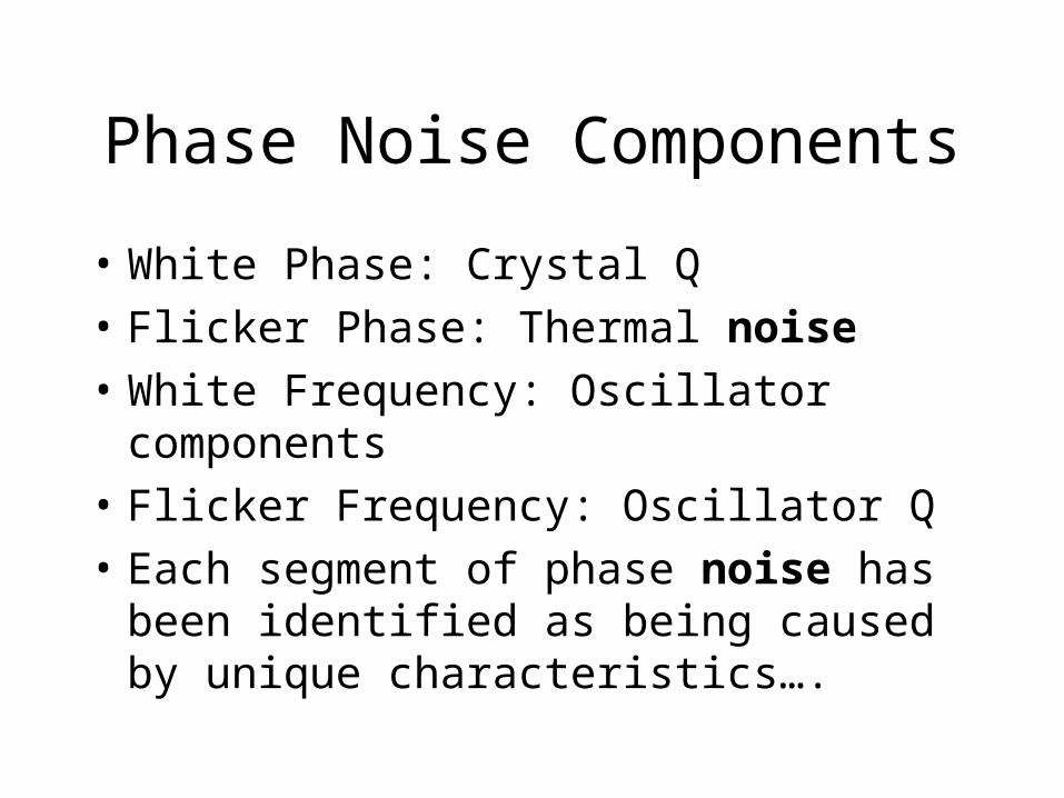
• White Phase: Crystal Q
• Flicker Phase: Thermal noise
• White Frequency: Oscillator components
• Flicker Frequency: Oscillator Q
• Each segment of phase noise has been identified as being caused by unique characteristics….
Random Walk Noise
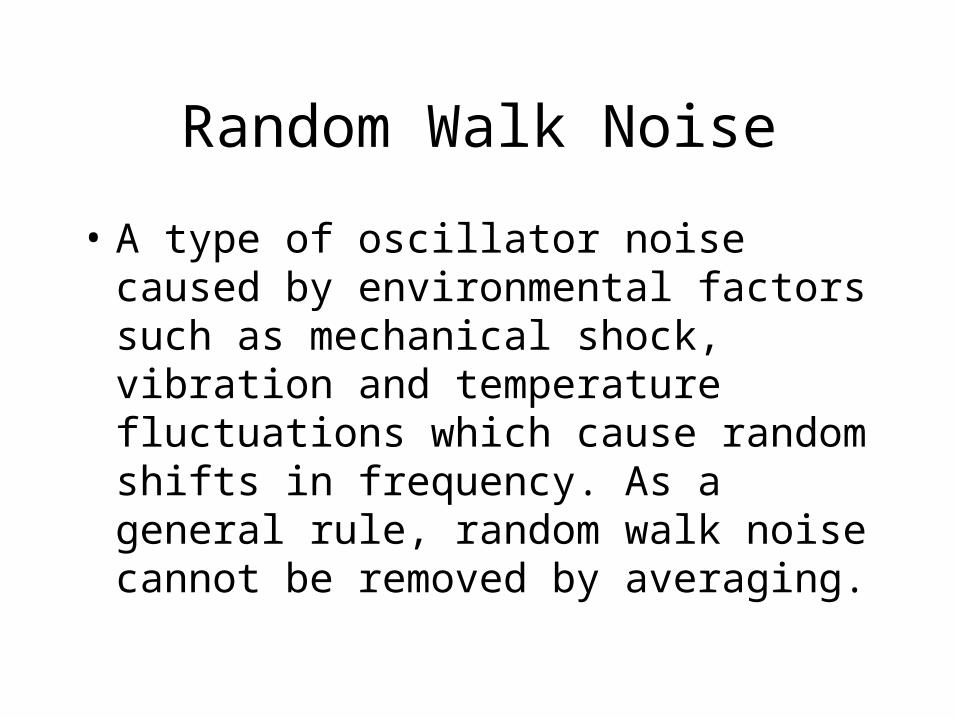
• A type of oscillator noise caused by environmental factors such as mechanical shock, vibration and temperature fluctuations which cause random shifts in frequency. As a general rule, random walk noise cannot be removed by averaging.
Flicker Noise
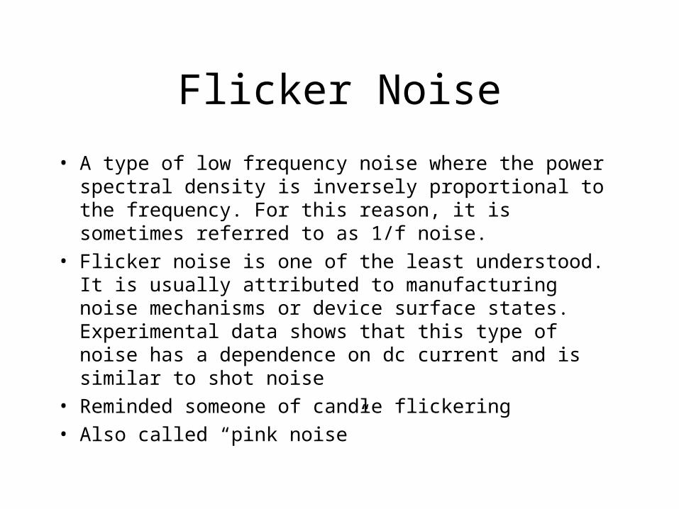
• A type of low frequency noise where the power spectral density is inversely proportional to the frequency. For this reason, it is sometimes referred to as 1/f noise.
• Flicker noise is one of the least understood. It is usually attributed to manufacturing noise mechanisms or device surface states. Experimental data shows that this type of noise has a dependence on dc current and is similar to shot noise
• Reminded someone of candle flickering
• Also called “pink noise”
White Noise
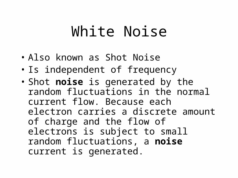
• Also known as Shot Noise• Is independent of frequency• Shot noise is generated by the random
fluctuations in the normal current flow. Because each electron carries a discrete amount of charge and the flow of electrons is subject to small random fluctuations, a noise current is generated.
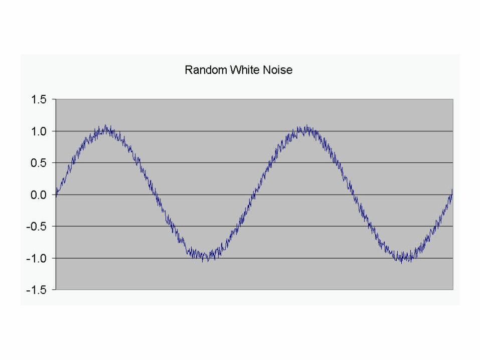
Random White Noise
How is clock performance characterized?
• Allan Variance
• Drift
• Phase Noise
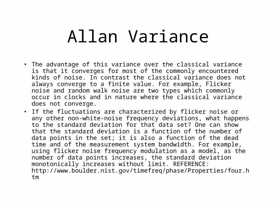
Allan Variance
• The advantage of this variance over the classical variance is that it converges for most of the commonly encountered kinds of noise. In contrast the classical variance does not always converge to a finite value. For example, Flicker noise and random walk noise are two types which commonly occur in clocks and in nature where the classical variance does not converge.
• If the fluctuations are characterized by flicker noise or any other non-white-noise frequency deviations, what happens to the standard deviation for that data set? One can show that the standard deviation is a function of the number of data points in the set; it is also a function of the dead time and of the measurement system bandwidth. For example, using flicker noise frequency modulation as a model, as the number of data points increases, the standard deviation monotonically increases without limit. REFERENCE: http://www.boulder.nist.gov/timefreq/phase/Properties/four.htm
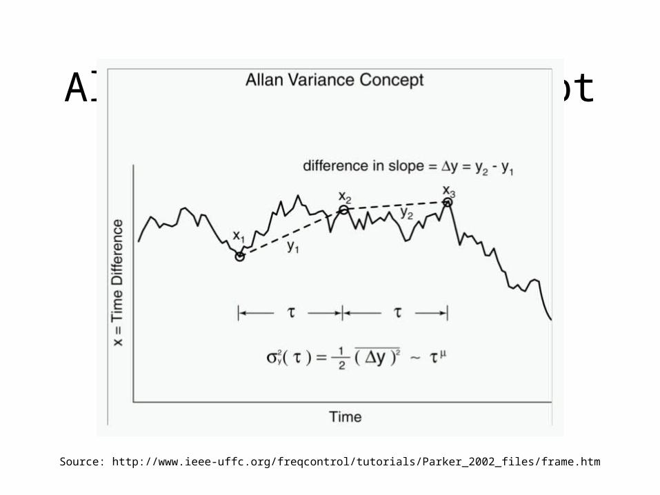
Allan Variance Concept
Source: http://www.ieee-uffc.org/freqcontrol/tutorials/Parker_2002_files/frame.htm
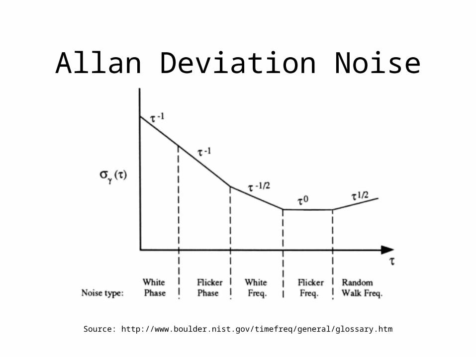
Allan Deviation Noise
Source: http://www.boulder.nist.gov/timefreq/general/glossary.htm

Modified Allan Variance
• The Allan variance filter cannot distinguish between white Phase Noise and flicker Phase Noise.
• Synchronization networks require frequency standards which have good time and phase stability.
• White PM and flicker PM levels are an important indicator of time/ phase stability.
• Therefore, another algorithm is necessary to distinguish between the various noise components.
• Modified Allan variance (MVAR) will discern white PM and flicker PM.
Modified Allan Noise
Quartz Crystal
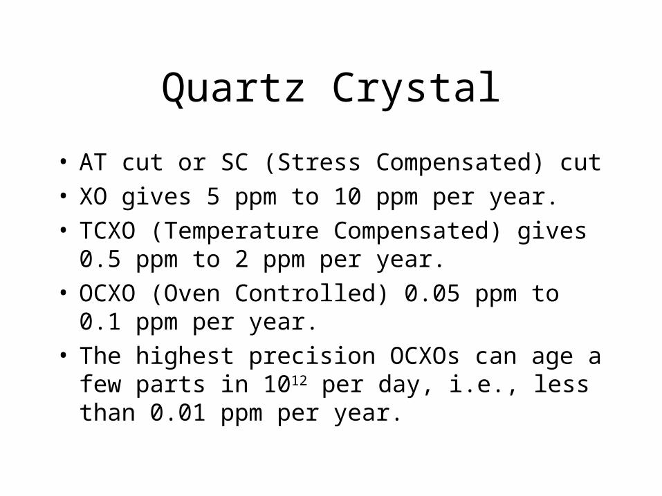
• AT cut or SC (Stress Compensated) cut• XO gives 5 ppm to 10 ppm per year.• TCXO (Temperature Compensated) gives 0.5 ppm
to 2 ppm per year.• OCXO (Oven Controlled) 0.05 ppm to 0.1 ppm
per year.• The highest precision OCXOs can age a few parts
in 1012 per day, i.e., less than 0.01 ppm per year.
Quartz Crystal Cont
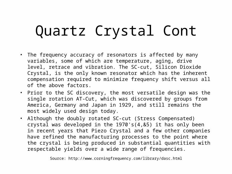
• The frequency accuracy of resonators is affected by many variables, some of which are temperature, aging, drive level, retrace and vibration. The SC-cut, Silicon Dioxide Crystal, is the only known resonator which has the inherent compensation required to minimize frequency shift versus all of the above factors.
• Prior to the SC discovery, the most versatile design was the single rotation AT-Cut, which was discovered by groups from America, Germany and Japan in 1929, and still remains the most widely used design today.
• Although the doubly rotated SC-cut (Stress Compensated) crystal was developed in the 1970's(4,&5) it has only been in recent years that Piezo Crystal and a few other companies have refined the manufacturing processes to the point where the crystal is being produced in substantial quantities with respectable yields over a wide range of frequencies.
Source: http://www.corningfrequency.com/library/dasc.html
Rubidium
• Resonance 6,834,682,608 Hz• Optical pumping relies on the natural
coincidence of optical resonant frequencies between 85Rb and 87Rb, both at 795nm.
• Good short term stability• Poor long term stability• Used in VLBI until superseded by
Hydrogen Maser
Cesium
• Resonance at 9,192,631,770 Hz by definition of the second
• C-Field
• Tube life approx 3 years
• Cost of used HP 5061A on eBay approx $1500
• Cost of new tube is about $10K
• While cesium clocks have excellent long-term stability, the greatest weakness is the short-term stability caused by shot noise in the cesium beam.
• Not used for VLBI because of poor short term stability
Hydrogen Maser
• Resonance at 1420MHz
• Active and Passive designs.
• Currently the most stable frequency standard for averaging times between 103 and 104 seconds where stabilities as good as 7x10-16 are reached.
• Hydrogen masers are used as VLBI standards because of their excellent short term stability.
• Their long-term accuracy, however, is subject to drift.
• H-Maser Oscillators have a wear out mechanism, mainly from Hydrogen depletion and Ion Pump failures, which begin to show up in 3 to 5 years for active masers and 5 to 7 years for passive masers.
• Cost >$60K to >$200K
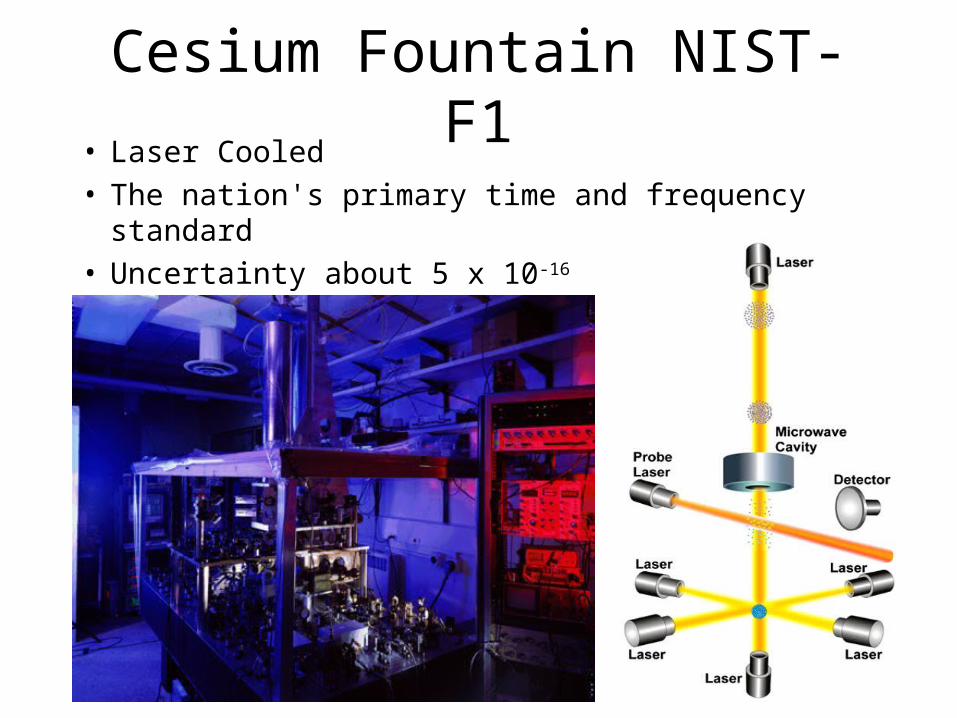
Cesium Fountain NIST-F1• Laser Cooled• The nation's primary time and frequency standard• Uncertainty about 5 x 10-16
Time Scales
• TAI
• UTC
• UT1
• GPS
• Loran
• TDB – Barycentric Dynamical Time
TAI timescale
• The reference used is International Atomic Time (TAI), a time scale calculated at the BIPM using data from some two hundred atomic clocks in over fifty national laboratories.
• TAI is a uniform and stable scale which does not, therefore, keep in step with the slightly irregular rotation of the Earth.
Leap Seconds
• Currently 13 leap seconds (+1 in 2007)• As of 2007 these leaps have always been positive
UT1 timescale
• is the principal form of Universal Time.• It is computed from the raw observed UT0 by correcting UT0 for
the effect of polar motion on the longitude of the observing site.• UT1 is the same everywhere on Earth, and is proportional to the
true rotation angle of the Earth with respect to a fixed frame of reference.
• Since the rotational speed of the earth is not uniform, UT1 has an uncertainty of plus or minus 3 milliseconds per day.
• The ratio of UT1 to mean sidereal time is defined to be 0.997269566329084 − 5.8684×10⁻¹¹T + 5.9×10⁻¹⁵T², where T is the number of Julian centuries of 36525 days each that have elapsed since JD 2451545.0 (J2000)
UTC
• Such a scale is Coordinated Universal Time (UTC), which is identical with TAI except that from time to time a leap second is added to ensure that, when averaged over a year, the Sun crosses the Greenwich meridian at noon UTC to within 0.9 s
• (Coordinated Universal Time) is an atomic timescale that approximates UT1.
• It is the international standard on which civil time is based.• It ticks SI seconds, in step with TAI. It usually has 86400 SI
seconds per day, but is kept within 0.9 seconds of UT1 by the introduction of occasional intercalary leap seconds.
• When an accuracy better than one second is not required, UTC can be used as an approximation of UT1.
• The difference between UT1 and UTC is known as DUT1
UTC
• Official international time is Coordinated Universal Time, UTC
• UTC is a paper clock generated once a month by the Bureau International des Poids et Mesures, BIPM with data collected from about 230 atomic clocks in 50 labs around the world and distributed in BIPM Circular T.
• The method of time transfer is primarily common-view GPS and some Two-Way Satellite Time and Freq Transfer.
• Local representations of UTC are hardware clocks with ticks generated in real time, UTC(NIST) for example. Local UTC’s are estimations of UTC.
BIPM
USNO
• Source of GPS time
• 61 Atomic Clocks, 11 Hydrogen Masers and 50 HP-5071 Cesium
NIST
• http://www.boulder.nist.gov/timefreq/
• Traceability
Time and Frequency Transfer
• One-Way
• Common-View
• Two-Way
Common View Satellite
• GPS
• GOES (obsolete)
• GLONASS (partial)
• GALILEO (future)
• Fixed plus variable delay components
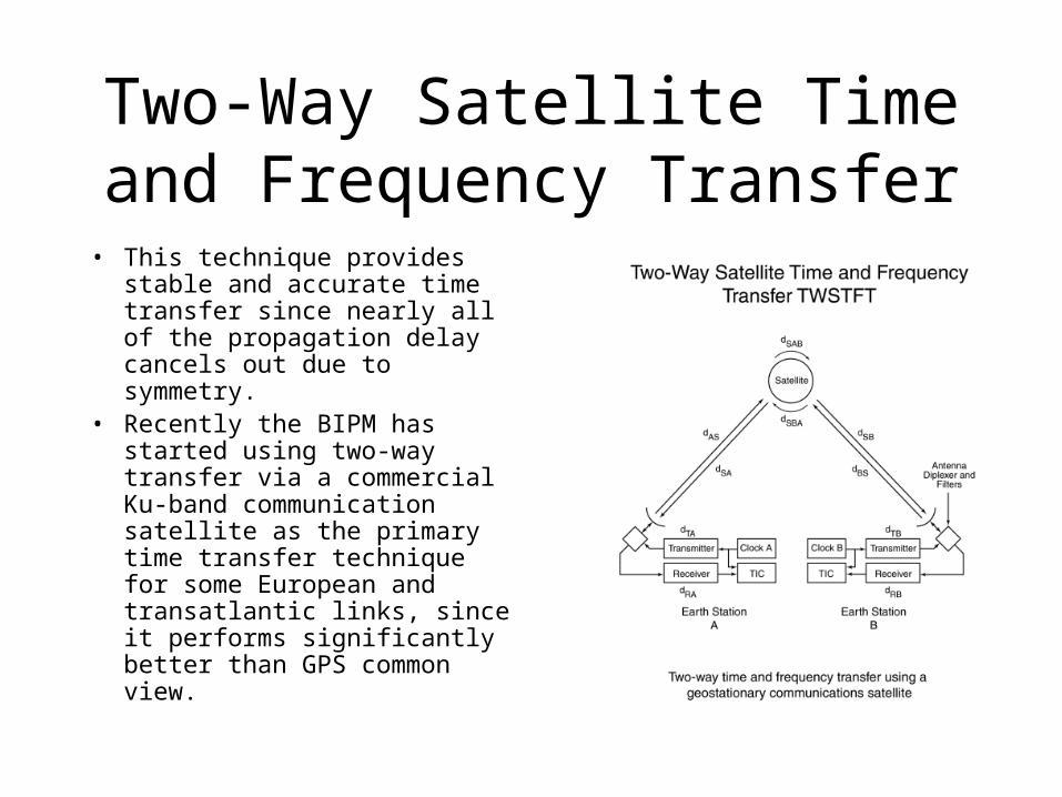
Two-Way Satellite Time and Frequency Transfer
• This technique provides stable and accurate time transfer since nearly all of the propagation delay cancels out due to symmetry.
• Recently the BIPM has started using two-way transfer via a commercial Ku-band communication satellite as the primary time transfer technique for some European and transatlantic links, since it performs significantly better than GPS common view.
Time Sources
• GPS
• Loran
• WWV / WWVB
GPS
• The Block IIF satellite, the latest generation of GPS vehicles that began replacing older satellites in 2001, feature four advanced atomic clocks composed of both cesium and rubidium technologies. These extremely accurate GPS atomic clocks keep time to within 8 nanoseconds a day.
• The atomic clocks aboard the satellites maintain their time to a very high degree of accuracy. However, there will always be a slight variation in clock rates from satellite to satellite. Close monitoring of the clock of each satellite from the ground permits the control station to insert a message in the signal of each satellite which precisely describes the drift rate of that satellite's clock. The insertion of the drift rate effectively synchronizes all of the GPS satellite clocks.
GPS Cont
• Excellent Long Term Stability• Poor Short Term Stability• Short term stability is degraded by satellite
orbital variations, ionosphere delay, troposphere delay, signal multipath from nearby terrain and buildings, receiver electronics, installation (antenna cable) and selective availability (presently turned off)
GPS Cont 2
• Receiver electronics have more or less delay
• Best units < 30ns rms ref to UTC
• Worst units > 1us rms ref to UTC
Loran• Long Range Navigation time, is an atomic time
scale implemented by the atomic clocks in Loran-C chain transmitter sites.
• Loran time was zero at 0h 1-Jan-1958 and since it is not perturbed by leap seconds it is now ahead of UTC by 23 seconds.
• Making a comeback after almost being cancelled as GPS backup
• System being upgraded to enhanced version known as eLoran
Loran Cont
• US Public Law 100-223, Section 310 requires the control the transmission of LORAN signals to within +/- 100 nanoseconds of UTC at times of coincidence (TOC).
• The Coast Guard has worked with USNO to steer LORAN transmissions to UTC
• USNO monitors & measures LORAN time differences (TD) in far field to determine difference between LORAN Chain & UTC
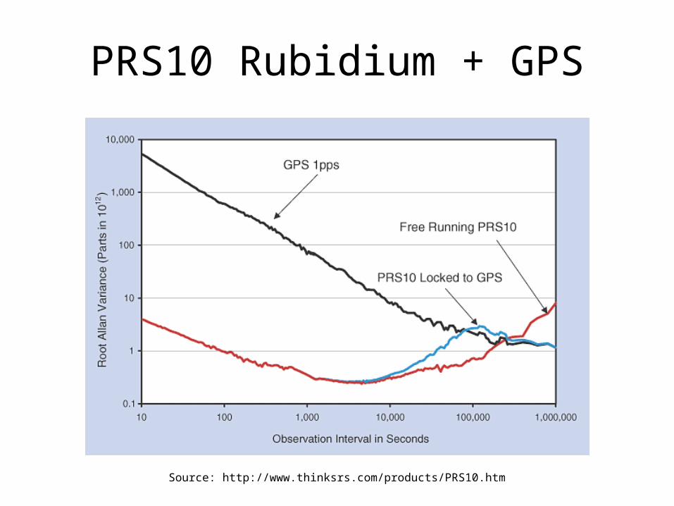
PRS10 Rubidium + GPS
Source: http://www.thinksrs.com/products/PRS10.htm
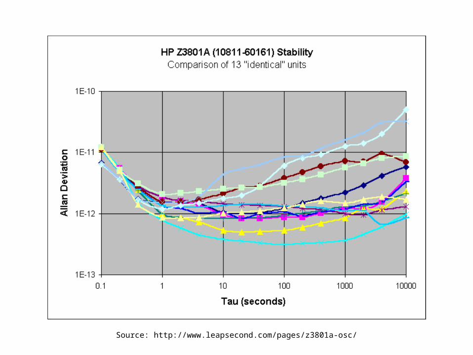
HP Z3801A Stability
Source: http://www.leapsecond.com/pages/z3801a-osc/

Comparison of Frequency Standards
Source: http://www.ieee-uffc.org/freqcontrol/quartz/vig/vigcomp.htm

Allan Deviation Comparison
Source: http://www.leapsecond.com/museum/manyadev.gif
Equipment Sources
• eBay
• Stanford Research PRS10
• Garmin
• Rubidium Efratom FRS-C
• GPS / Motorola Oncore
Information Sources
• http://www.leapsecond.com
• http://www.boulder.nist.gov/timefreq/
Conclusion
• Atomic Clocks are practical and affordable for Amateur Radio Astronomy.
• The combination using a Rubidium disciplined to GPS gives good short and long term performance.
• Opens up the possibility of amateur VLBI and other scientifically meaningful measurements.
Recommendations
• Use equipment with external 10MHz reference inputs
• Mfg / Vendors should design equipment to accept external 10MHz reference
Questions?
Clock History
• Christian Huygens’ (Galileo’s?) pendulum clock (1582) was stable to 1 min/day, but useless for moving platforms
• John Harrison’s “Marine Chronometer” (1761) kept time on a rolling ship to 0.2 s/day; determined longitude to 0.5 deg
• Quartz clocks have evolved from 1930’s to be stable to better than 1 part in 1013
HP 58540A
Brooks Shera's GPS Controller