atoms and lasers for precision timing and...
TRANSCRIPT
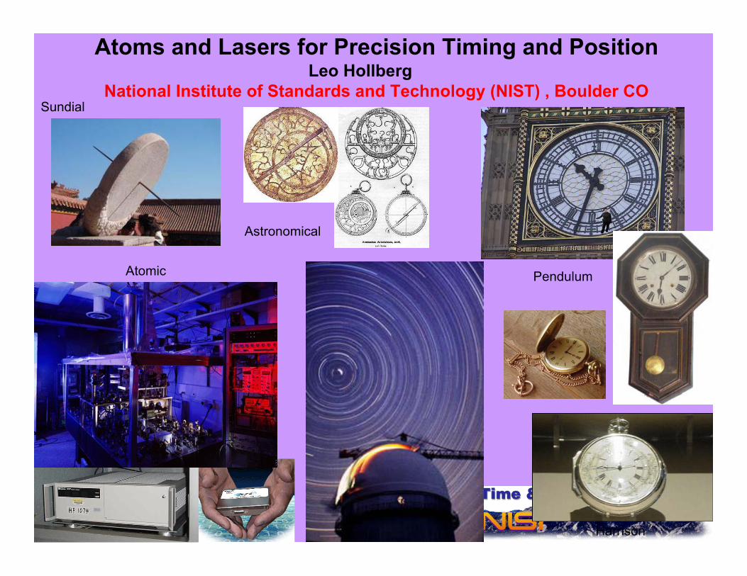
Atoms and Lasers for Precision Timing and PositionLeo Hollberg
National Institute of Standards and Technology (NIST) , Boulder CO
Astronomical
Sundial
Pendulum
Harrison
Atomic

Optical Frequency Measurements GroupNIST, Boulder
Optical ClocksChris OatesCold Ca Yann Le Coq → (SYRTE, Paris)Jason Stalnaker → (Oberlin)Guido Wilpers (Germany/NPL-UK)Anne Curtis (CU → NPL-UK)Kristin Beck (Rochester, SURF)Cold Yb Chad Hoyt (→ Bethel College)Zeb Barber (CU) Valeriey Yudin (Russia)Aleksei Taichanachev (Russia)Nathan Lemke (CU)Nicola Poli (LENS, Italy)
fs Frequency CombsScott Diddams
Tara Fortier (LANL)Jason Stalnaker → (Oberlin)
Qudsia Quraishi (CU)Stephanie Meyer (C)U)
Albrecht Bartels → (Konstance)L-S Ma, Z. Bi, (ECNU-BIPM)Y. Kobayashi (AIST Japan)Vela Mbele (South Africa)
Matt Kirchner (CU)Andy Weiner* (Purdue)
Danielle Braje
Optical Length MetrologyRichard Fox
•$$ NIST, DARPA-MTO, ONR-CU-MURI, NASA, LANL
Chip Scale Atomic Devicesclocks, magnetometers …
John KitchingSvenja Knappe (Germany)Peter Schwindt (Sandia)
Vishal Shah → (Princeton)Vladi Gerginov (Bulgaria)Ying-Ju Wang (Taiwan)
Clark GriffithAndy Geraci
Hugh RobinsonLiz Donley
Eleanor Hodby (England)Alan Brannon (CU)Brad Lindseth (CU)Matt Eardley (CU)
Susan SchimaLucas Willis (LSU, SURF)Nicolas VanMeter (SURF)
NIST Opto-ElectronicsNate Newbury, Bill Swan ...
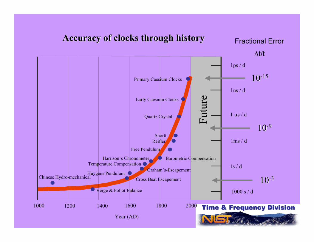
Accuracy of clocks through historyAccuracy of clocks through history
Year (AD)
Chinese Hydro-mechanical
Verge & Foliot Balance
Huygens Pendulum
Free Pendulum
Barometric Compensation
Shortt
Quartz Crystal
Early Caesium Clocks
Primary Caesium Clocks
Reifler
Harrison’s Chronometer
Graham’s-Escapement
Cross Beat Escapement
1000 s / d
1000 1200 1400 1600 1800 2000
1s / d
1ms / d
1 µs / d
1ns / d
1ps / d
Temperature Compensation
Futu
re
1010-9-9
1010-3-3
1010-15-15
Fractional Error
Δt/t
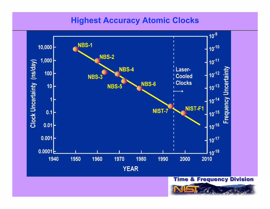
Highest Accuracy Atomic Clocks
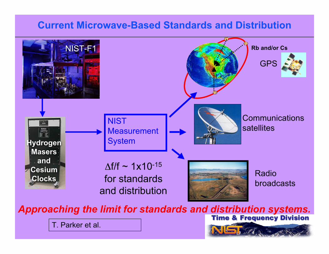
Current Microwave-Based Standards and Distribution
Approaching the limit for standards and distribution systems.
NISTMeasurementSystemHydrogen
Masersand
CesiumClocks
NIST-F1
GPS
Communicationssatellites
Radiobroadcasts
Δf/f ~ 1x10-15
for standardsand distribution
Rb and/or Cs
T. Parker et al.
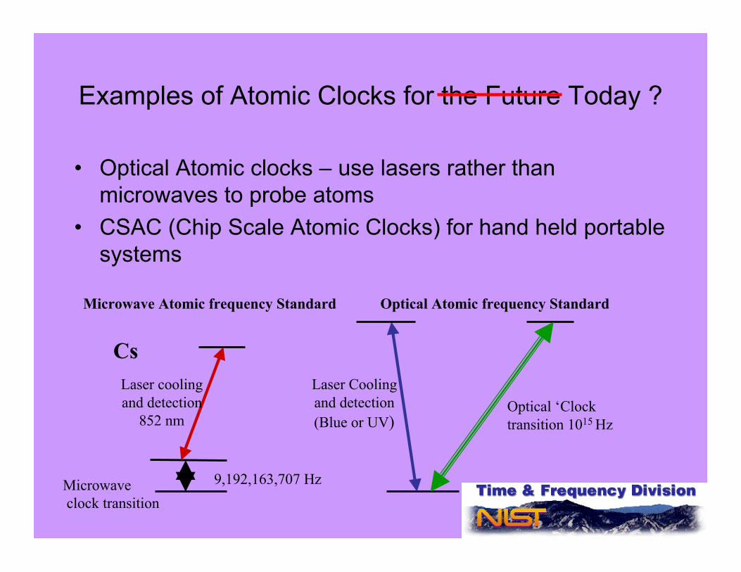
Examples of Atomic Clocks for the Future Today ?
• Optical Atomic clocks – use lasers rather thanmicrowaves to probe atoms
• CSAC (Chip Scale Atomic Clocks) for hand held portablesystems
Optical Atomic frequency Standard
Cs
9,192,163,707 Hz
Laser coolingand detection
852 nm
Laser Coolingand detection(Blue or UV)
Optical ‘Clocktransition 1015 Hz
Microwave Atomic frequency Standard
Microwave clock transition

HeNe 633 nm
Frequency Lock electronics
!"
n
c=
I2
Michelson Interferometer,BIPM, Paris, circa 1910 ?
Relative position, dimensional metrology, surveying instruments relyon the fixed speed of light c and frequency references
discharge lamps, lasers and purely classical optics
Lunar ranging w/laser pulses

NIST F1, Cs atomic fountain clockPrimary frequency Std. of U.S.
S. Jefferts, L. Donley, T. Heavner, T. Parker

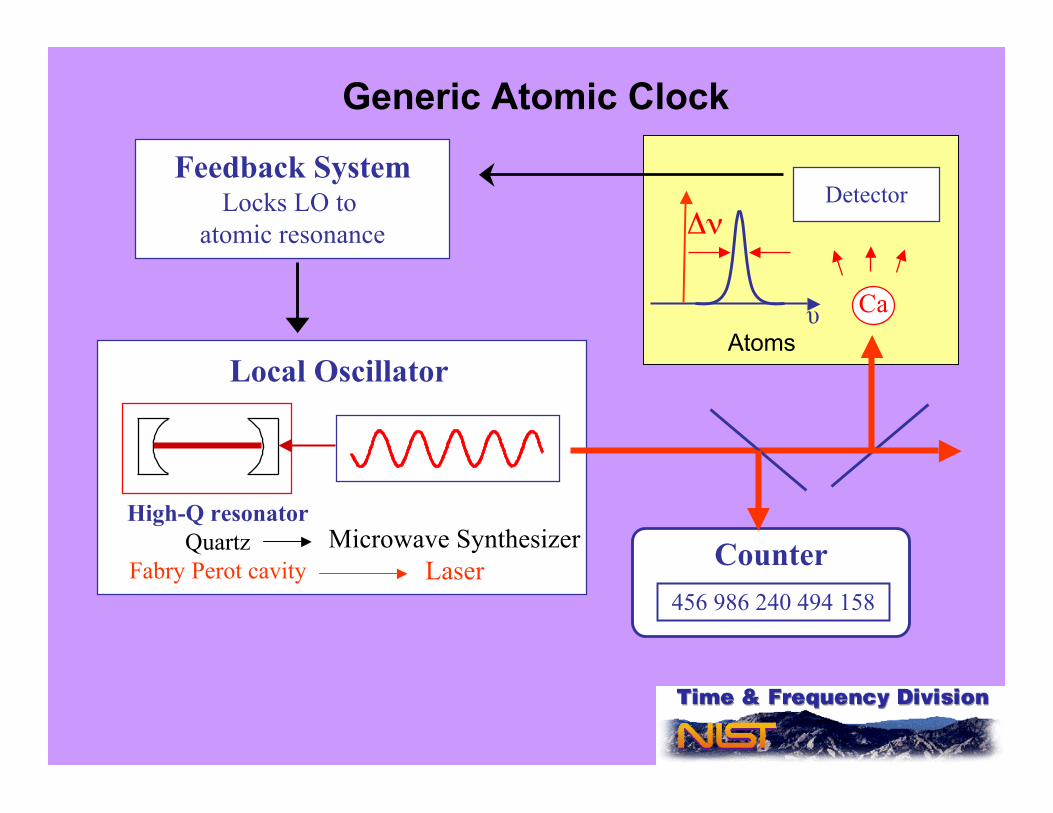
Δν
Ca
Detector
Local Oscillator
High-Q resonatorQuartz
Fabry Perot cavity
Feedback SystemLocks LO to
atomic resonance
Microwave SynthesizerLaser
456 986 240 494 158
Counter
υ
Generic Atomic Clock
Atoms

Advantages of Optical Clocks Quantum Projection Noise Fractional Frequency instability ~
! = observation time
N = number of atoms
5
10
15
0
010
10
10!!
microwave
optical
f
f
• Large number of atoms 106 or more• High signal/noise• Possibility of lattices
Candidate neutral atomsCa, Sr, Yb, Mg, H, Ag, Hg…
One atomic clock is always “perfect”Two similar clocks -- hard to detect systematic errorsDifferent types of clocks can determine most accurate and stable
Clocktransition
S
1P3P or D
Cooling/detectiontransition
y!"
"#
atoms
cycle
N
TK
0
$=
Δν
ν0 ν
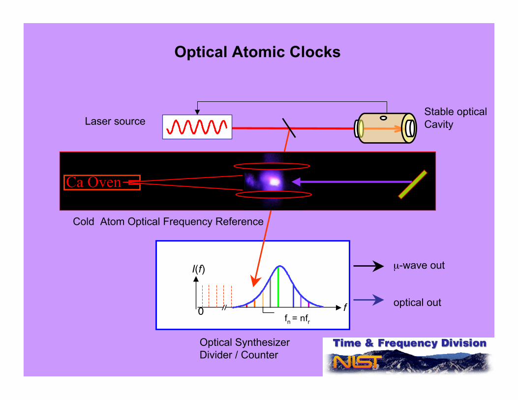
Optical SynthesizerDivider / Counter
Cold Atom Optical Frequency Reference
µ-wave out
optical out
fr
0
I(f)
f
Ca Oven
fn = nfr
Stable opticalCavityLaser source
Optical Atomic Clocks
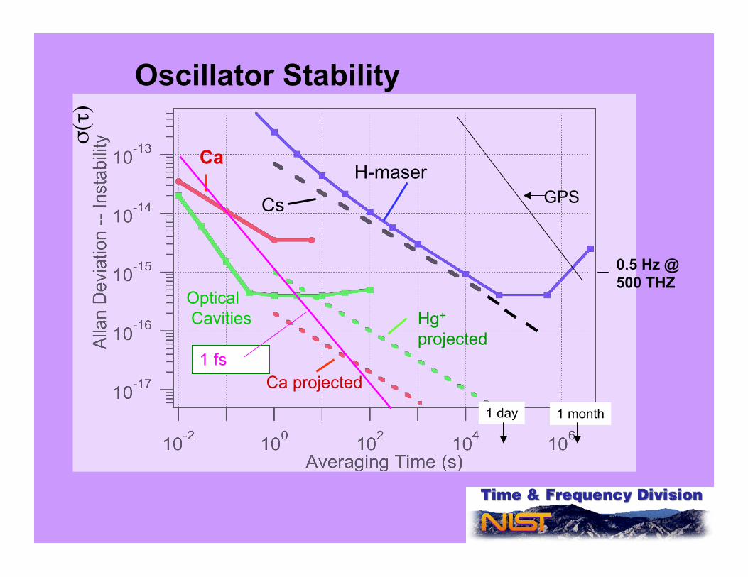
σ(τ
)
H-maser
Cs
Hg+
projected
Ca
1 day 1 month
Ca projected
Oscillator Stability
GPS
Optical Cavities
0.5 Hz @500 THZ
1 fs
Frac
tiona
l Fre
quen
cy U
ncer
tain
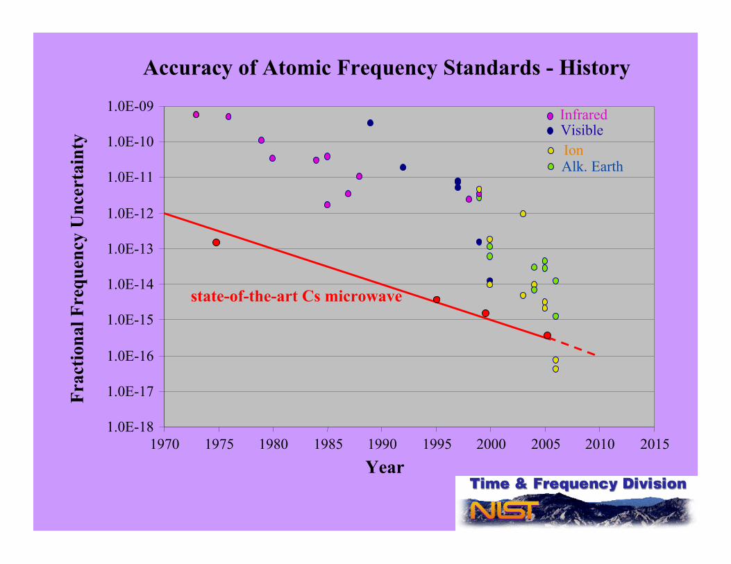
tyAccuracy of Atomic Frequency Standards - History
1.0E-18
1.0E-17
1.0E-16
1.0E-15
1.0E-14
1.0E-13
1.0E-12
1.0E-11
1.0E-10
1.0E-09
1970 1975 1980 1985 1990 1995 2000 2005 2010 2015Year
state-of-the-art Cs microwave
Ion
InfraredVisible
Alk. Earth
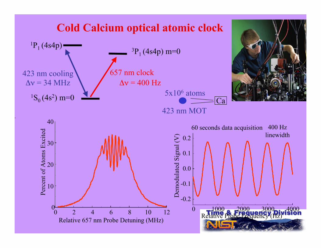
Cold Calcium optical atomic clock
Relative 657 nm Probe Detuning (MHz)
423 nm coolingΔν = 34 MHz
657 nm clock
1S0 (4s2) m=0
1P1 (4s4p)
Δν = 400 Hz
3P1 (4s4p) m=0
0
10
20
30
40
Perc
ent o
f Ato
ms E
xcite
d
0 2 4 6 8 10 12 0 1000 2000 3000 4000Relative Probe Frequency (Hz)
-0.2
-0.1
0.0
0.1
0.2
Dem
odul
ated
Sig
nal (
V)
60 seconds data acquisition 400 Hzlinewidth
423 nm MOT
5x10⁶ atomsCa
-20 -15 -10 -5 0 5 10 15 200.00
0.05
0.10
0.15
0.20
0.25
0.30
0.35
0.40
0.45
0.50
0.55
Ato
m n
um
be
r [a
.u.]
Frequency offset [Hz]
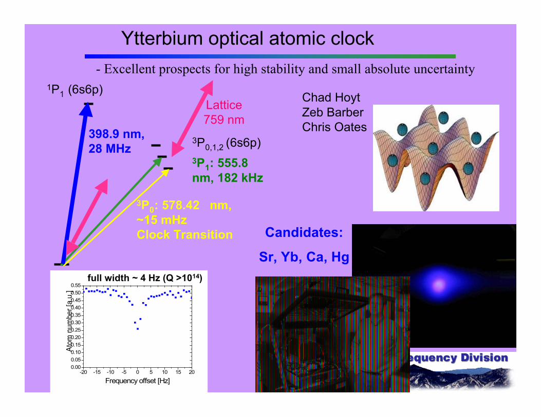
Ytterbium optical atomic clock
Chad Hoyt Zeb BarberChris Oates
- Excellent prospects for high stability and small absolute uncertainty
398.9 nm,28 MHz
3P0: 578.42 nm,~15 mHzClock Transition
1P1 (6s6p)
3P1: 555.8nm, 182 kHz
3P0,1,2 (6s6p)
Lattice759 nm
full width ~ 4 Hz (Q >1014)
Candidates:
Sr, Yb, Ca, Hg
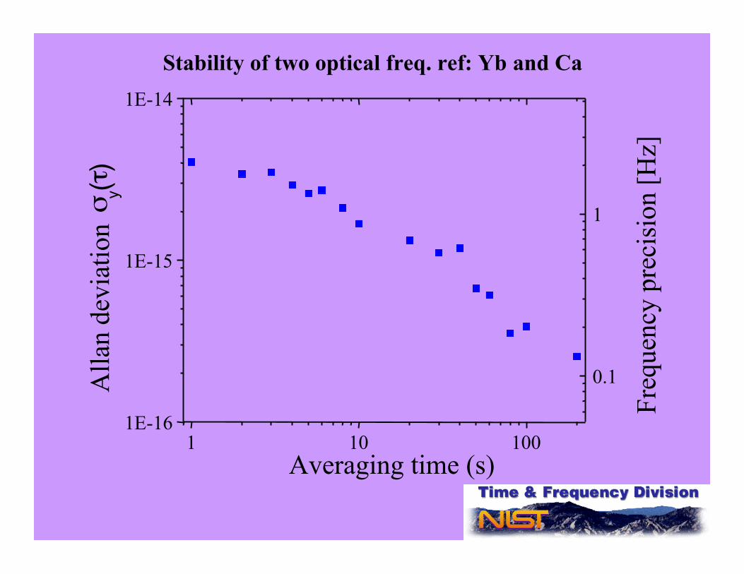
Stability of two optical freq. ref: Yb and Ca
1 10 1001E-16
1E-15
1E-14
0.1
1
Alla
n de
viat
ion σ y(τ
)
Averaging time (s)
Fre
quen
cy p
reci
sion
[Hz]
Δν
Ca
Detector
Local Oscillator
High-Q resonatorQuartz
Fabry Perot cavity
Feedback SystemLocks LO to
atomic resonance
Microwave SynthesizerLaser
456 986 240 494 158
Counter
υ
Generic Atomic Clock
Atoms

Enthusiasm for Optical Atomic Clocks and fs Combs
Jan Hall
Ted Hänsch
Nobel Prize2005
ScottDiddams
TaraFortier
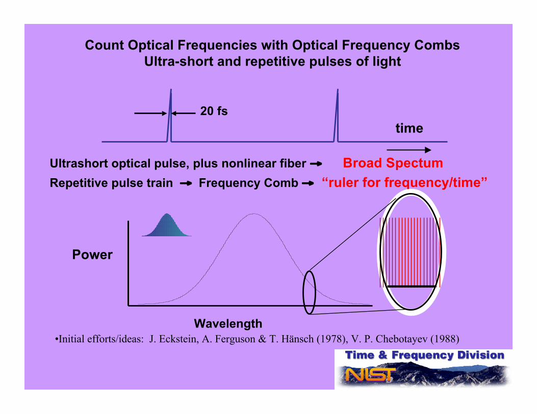
20 fs
Ultrashort optical pulse, plus nonlinear fiber → Broad SpectumRepetitive pulse train → Frequency Comb → “ruler for frequency/time”
Count Optical Frequencies with Optical Frequency CombsUltra-short and repetitive pulses of light
time
Wavelength
Power
•Initial efforts/ideas: J. Eckstein, A. Ferguson & T. Hänsch (1978), V. P. Chebotayev (1988)
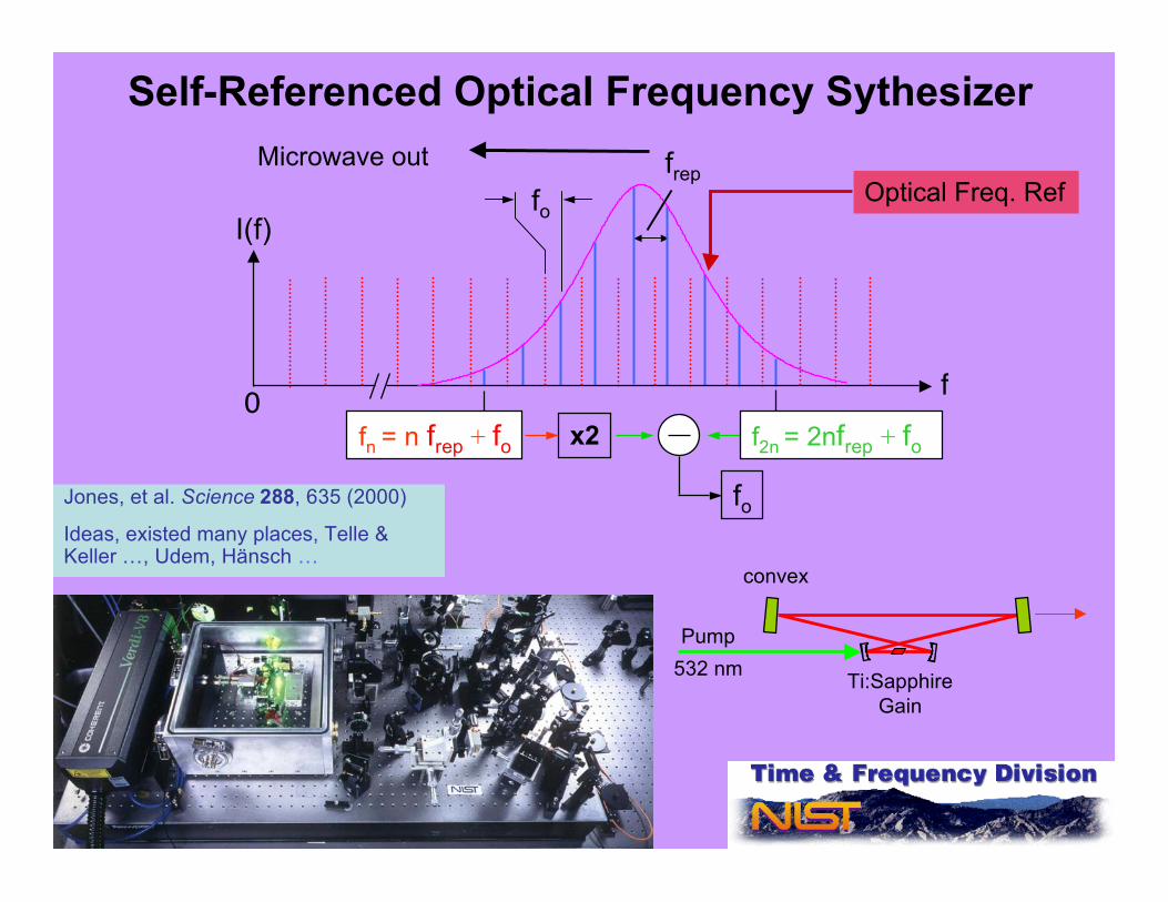
I(f)
f
fo
0fn = n frep + fo
frep
x2 f2n = 2nfrep + fo
fo
Self-Referenced Optical Frequency Sythesizer
Jones, et al. Science 288, 635 (2000)
Ideas, existed many places, Telle &Keller …, Udem, Hänsch …
Optical Freq. Ref
Ti:SapphireGain
convex
532 nmPump
Microwave out

The frequency of a mode is simply FN = N * frep – f0Where N is and integer ~ 10
6
Frequencyfr=1/ τr.t.
f0
frep ~ 1000 MHz
0
0
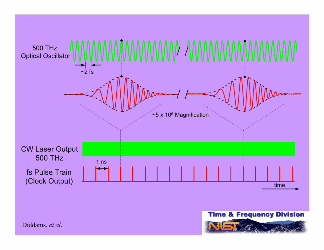
~5 x 10⁵ Magnification
fs Pulse Train(Clock Output)
CW Laser Output500 THz
time
Diddams, et al.
1 ns
~2 fs
500 THz Optical Oscillator
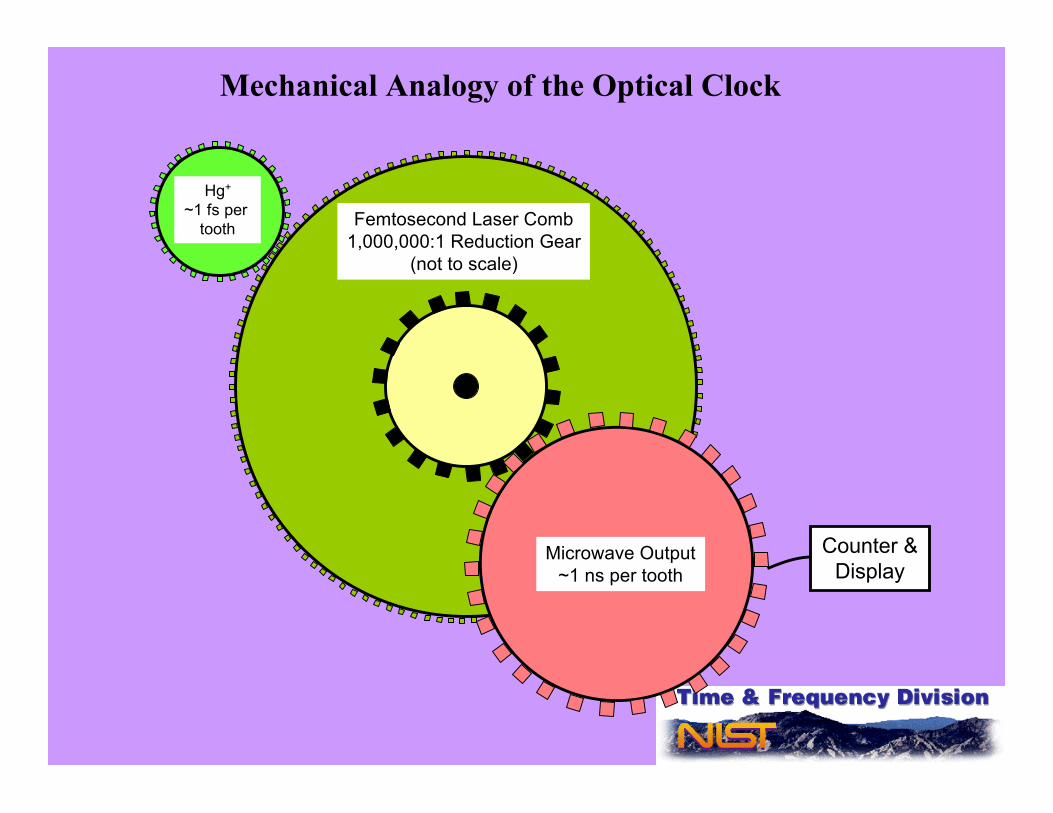
Microwave Output~1 ns per tooth
Hg+
~1 fs per tooth Femtosecond Laser Comb
1,000,000:1 Reduction Gear(not to scale)
Mechanical Analogy of the Optical Clock
Counter &Display
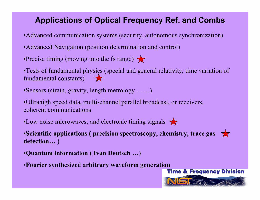
Applications of Optical Frequency Ref. and Combs
•Advanced communication systems (security, autonomous synchronization)
•Advanced Navigation (position determination and control)
•Precise timing (moving into the fs range)
•Tests of fundamental physics (special and general relativity, time variation offundamental constants)
•Sensors (strain, gravity, length metrology ……)
•Ultrahigh speed data, multi-channel parallel broadcast, or receivers, coherent communications
•Low noise microwaves, and electronic timing signals
•Scientific applications ( precision spectroscopy, chemistry, trace gasdetection… )
•Quantum information ( Ivan Deutsch …)
•Fourier synthesized arbitrary waveform generation

fµ-wave= fopt/Nµ-wave out
Opticalreference
0
I(f)
ffµ-wave
fopt
PUMP
OCM3
M1 M2
fs frequency combs as Optical Frequency DividerGeneration of microwaves with low phase noise
1 ns
time
Optical outputs
30ps
Microwave pulses
20 fs
I(f)
fMicrowave frequency
Microwave comb w/1 GHz mode spacing
-160
-140
-120
-100
-80
-60
-40L(f
) dB
c/H
z
100
101
102
103
104
105
106
Frequency (Hz)
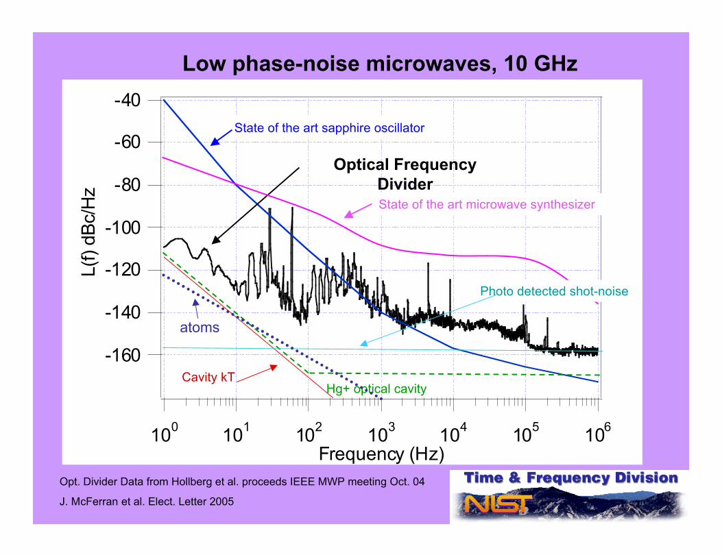
Low phase-noise microwaves, 10 GHz
Optical FrequencyDivider
State of the art sapphire oscillator
State of the art microwave synthesizer
Opt. Divider Data from Hollberg et al. proceeds IEEE MWP meeting Oct. 04
J. McFerran et al. Elect. Letter 2005
Hg+ optical cavityCavity kT
Photo detected shot-noise
atoms

Laser Source563 nm
linewidth ∆n <1Hz
Beat Frequency2(ƒAO + Δƒ + ƒN)
LO = 2ƒAO
Lock Δƒ = -ƒN
ƒ0
λ/4
PBS
Polarizer
AOM
ƒ0 + ƒAO + Δƒ
Angle-cutfiber facet
ƒAO + Δƒ
Polarization Control
λ/4
Fiber adds Noise ƒNDue to vibration, Δ
T…
ƒ0 + ƒAO + Δƒ + ƒN
Flat Fiber face
ƒ0 + ƒAO To Experment
Cancellation of Fiber Noise
Source Lab
ooo
Receiver Lab•For highest precision must useDoppler cancellation methodsto remove environmentalinduced phase shifts
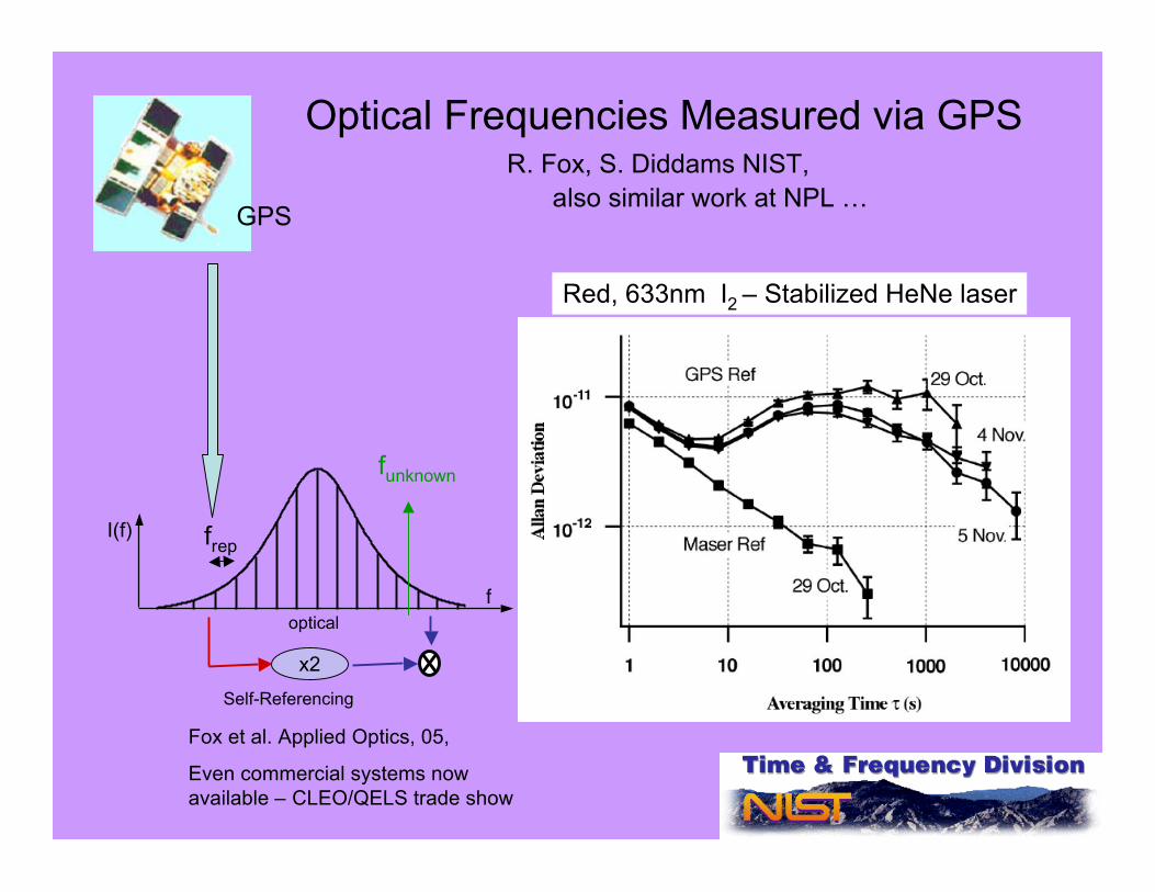
Optical Frequencies Measured via GPSR. Fox, S. Diddams NIST,
also similar work at NPL …
I(f)
foptical
x2Self-Referencing
frep
funknown
GPS
Fox et al. Applied Optics, 05,
Even commercial systems nowavailable – CLEO/QELS trade show
Red, 633nm I2 – Stabilized HeNe laser

Advanced cold atom clocks orLaser ranging/imaging in/from Space
Next generation Gracelaser ranging ?
PARCS
NASA
ACES
ESA
HYPER, …
T2L2ESA

CSADs TeamNIST Time and FrequencyJohn Kitching Svenja Knappe Vladislav Gerginov Vishal Shah Susan Schima Peter Schwindt Clark Griffith Brad Lindseth
Ying-Ju Wang Matt Eardley
Elizabeth Donley Eleanor Hodby Hugh G. Robinson
NIST Electromagnetics John Moreland Li-Anne Liew
University of ColoradoZ. PopovićA. BrannonJ. BreitbarthJ. MaclennanY. Li
CSAC
CSAM
Gyro
Dir. Coup.
MEMS
LO
Wall coatings
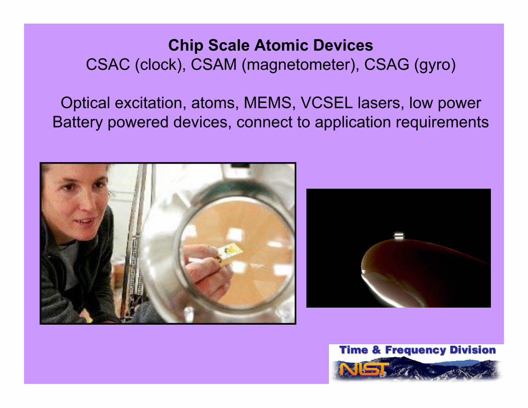
Chip Scale Atomic DevicesCSAC (clock), CSAM (magnetometer), CSAG (gyro)
Optical excitation, atoms, MEMS, VCSEL lasers, low powerBattery powered devices, connect to application requirements
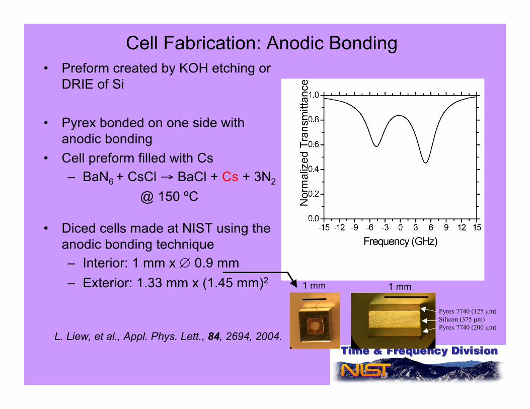
Cell Fabrication: Anodic Bonding• Preform created by KOH etching or
DRIE of Si
• Pyrex bonded on one side withanodic bonding
• Cell preform filled with Cs– BaN6 + CsCl → BaCl + Cs + 3N2
@ 150 ºC
• Diced cells made at NIST using theanodic bonding technique– Interior: 1 mm x ∅ 0.9 mm– Exterior: 1.33 mm x (1.45 mm)2
Pyrex 7740 (125 µm)Silicon (375 µm)Pyrex 7740 (200 µm)
L. Liew, et al., Appl. Phys. Lett., 84, 2694, 2004.
1 mm1 mm
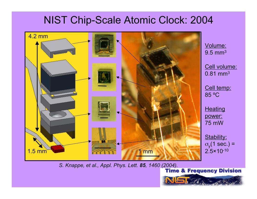
NIST Chip-Scale Atomic Clock: 2004
Volume:9.5 mm3
Cell volume:0.81 mm3
Cell temp:85 ºC
Heatingpower:75 mW
Stability:σy(1 sec.) =2.5×10⁻¹⁰
S. Knappe, et al., Appl. Phys. Lett. 85, 1460 (2004).
1 mm
4.2 mm
1.5 mm
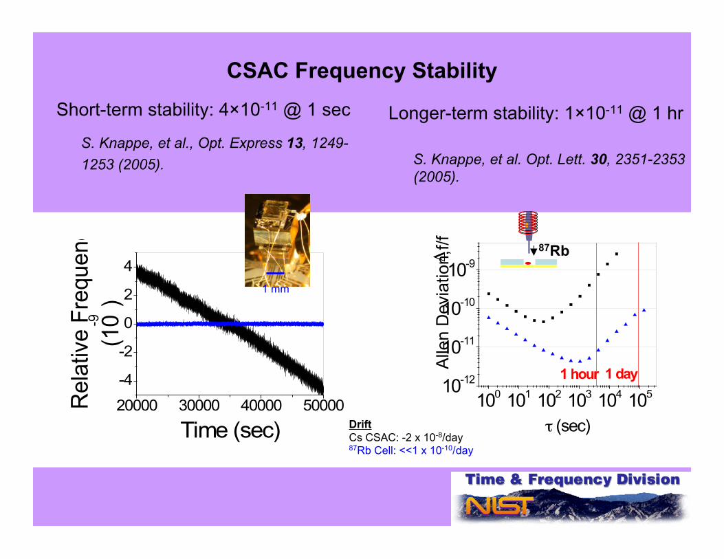
CSAC Frequency StabilityShort-term stability: 4×10-11 @ 1 sec
S. Knappe, et al., Opt. Express 13, 1249-1253 (2005).
Longer-term stability: 1×10-11 @ 1 hr
S. Knappe, et al. Opt. Lett. 30, 2351-2353(2005).
20000 30000 40000 50000
-4
-2
0
2
4
Rela
tive F
requency
(10-9
)
Time (sec)
1 mm
100
101
102
103
104
105
10-12
10-11
10-10
10-9
1 day1 hour
Alle
n D
evia
tion, !f/f
" (sec)
87Rb
DriftCs CSAC: -2 x 10⁻⁸/day87Rb Cell: <<1 x 10⁻¹⁰/day

(A Very Rough) Oscillator Comparison
Adapted from figure by R. Lutwak, Symmetricom
Quartz CrystalOscillators

Applications of Microfabricated Atomic Clocks
• Size (1 cm3)• Power (30 mW)• Precise timing: higher-performance, more reliable operation
Integration in portable, battery-operated devices
Key application areas:• Global positioning and navigation (GPS)
• Faster acquisition time• More precise altitude determination• Direct P(Y)/M code acquisition → anti-jam capability• Position solution with < 4 satellites visible
• Wireless communications, network synchronization• Fewer dropped cell phone calls• Avoidance of data accumulation
• Data logging, seismology, remote sensors…• Others we don’t even know about

GPS Positioning with < 4Satellites
τ1τ2
τ3
τ4
Atomic clock
?
(τ1, τ2, τ3, τ4)
(x, y, z, t)GPSReceiver

Commercialization of Chip-Scale Atomic ClocksHoneywell
(courtesy D. Youngner)Symmetricom/Draper/Sandia
(courtesy R. Lutwak)
RF output
Complete functioning CSACs
< 10 mWpower requirement
10 cm3
108 mW5×10-11 @ 100 s
1.7 cm3
57 mW4×10-12 @ 1 hr
bench wafer
Photo -detector
vcsel
Trans -Impedance Amp
optics
bench wafer
Photo -detector
vcsel
Trans -Impedance Amp
bench wafer
Photo -detector
vcsel
Trans -Impedance Amp
bench wafer
Photo -detector
vcsel
Trans -Impedance Amp
optics
top cap wafervacuum
gold reflectortitanium getter
soldersolder
top cap wafervacuum
gold reflectortitanium getter
soldersolder
optical pathoptical path
cavity wafer
rubidium +AR/N2
cavity wafercavity wafer
rubidium +AR/N2

Magnetometry with Chip-Scale Devices
Ato
m E
nerg
y
mFj
-2 -1 0 +1 +2
Hyperfinesplitting
Zeeman splitting
ћωHF
ћωL = ½µΒΒ
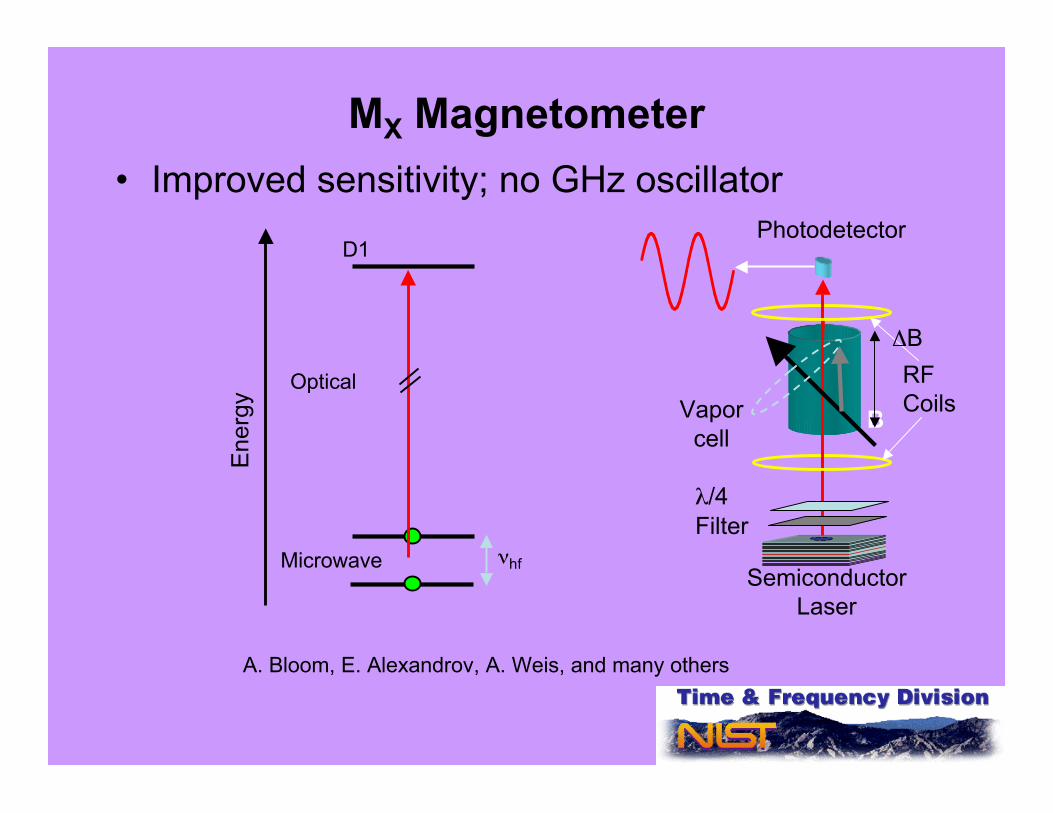
MX Magnetometer
Vaporcell
SemiconductorLaser
Photodetector
B
RFCoils
λ/4Filter
Optical
Microwave νhf
Ene
rgy
D1
A. Bloom, E. Alexandrov, A. Weis, and many others
• Improved sensitivity; no GHz oscillator
ΔB
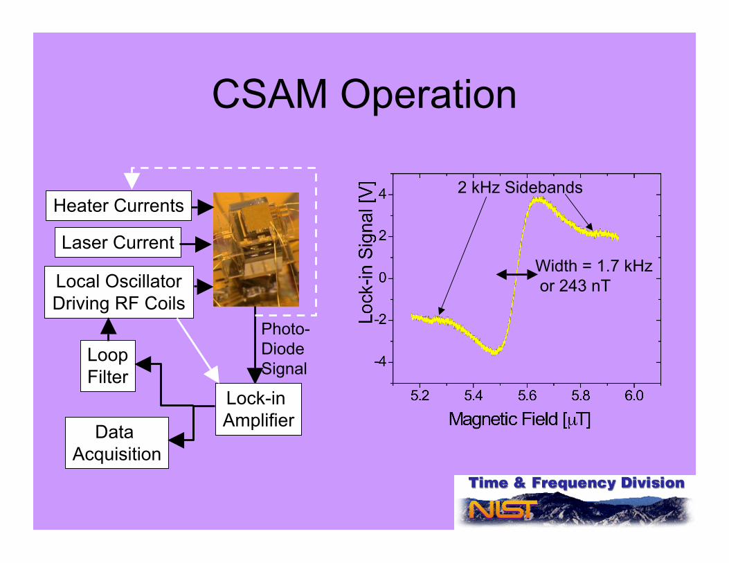
CSAM Operation
2 kHz Sidebands
Width = 1.7 kHz or 243 nT
Heater Currents
Laser Current
Local OscillatorDriving RF Coils
Lock-in Amplifier
Photo-DiodeSignal
Data Acquisition
LoopFilter
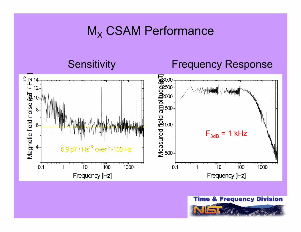
MX CSAM Performance
Sensitivity Frequency Response
F3dB = 1 kHz
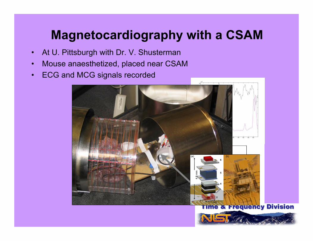
Magnetocardiography with a CSAM• At U. Pittsburgh with Dr. V. Shusterman• Mouse anaesthetized, placed near CSAM• ECG and MCG signals recorded
4.5
mm
1.7 mm12
3
6
4
(a) (b)
5
4.5
mm
1.7 mm12
3
6
4
(a) (b)
5
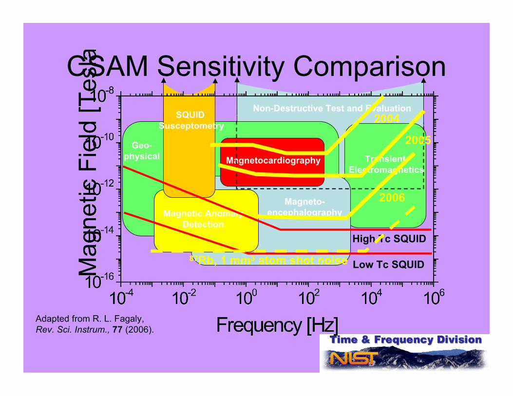
CSAM Sensitivity Comparison
Geo-physical Transient
Electromagnetics
Magnetic AnomalyDetection
Magnetocardiography
Magneto-encephalography
SQUID Susceptometry
Non-Destructive Test and Evaluation2004
2005
2006
High Tc SQUID
Low Tc SQUID87Rb, 1 mm3 atom shot noise
Adapted from R. L. Fagaly, Rev. Sci. Instrum., 77 (2006).
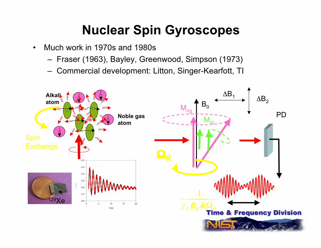
Nuclear Spin Gyroscopes• Much work in 1970s and 1980s
– Fraser (1963), Bayley, Greenwood, Simpson (1973)– Commercial development: Litton, Singer-Kearfott, TI
Alkaliatom
Noble gasatom
B0
ΔB1 ΔB2Mng
MAlPD
SpinExchange
Time
100 µs
58 ms 0
1
N RB! +"
0
1
NB!
ΩR
FFT of Lock-In Signal
! = 100 us, S=200 mV
f (Hz)
0 5 10 15 20 25
PS
D (V
rms/rtH
z)
1e-6
1e-5
1e-4
1e-3
1e-2
1e-1
Lock In signal Fit includes linear drift
f=y0+c*x+a*exp(-x/d)*cos(2*3.14159265359*x/b)
t (s)
0 5 10 15 20
S (V
)
-0.8
-0.7
-0.6
-0.5
-0.4
-0.3
-0.2
T2 ~ 6 s
129Xe

OPTICS + atoms/molecules new capabilities• Cold atoms, stable lasers and femotosecond optical frequency combs
having tremendous impact on fundamental science, precision measurements,and metrology
• Optical/Laser era in frequency standards and precision timing, spectroscopy …• Already providing lowest phase-noise, timing jitter
– fs jitter soon common place– Lowest phase noise microwave signals
• Some applications of stable sources and combs– new capabilities for science fundamental physics– Ultralow timing jitter, ultrafast sampling A/D, synchronization– Frequency standard precision spanning the spectrum 1 GHz to 500 THz +– Stabilized fs optical frequency combs enabling several new directions in
spectroscopy, Fourier synthesis
• Chip Scale Atomic Devices – practical route to bring atomic precision tofield devices– Combination of MEMS, diode lasers, atomic physics– Clocks, Magnetometers, Gyros ..