atr-021 pavement structural design training manual
TRANSCRIPT

PAVEMENT STRUCTURAL DESIGNTRAINING MANUAL
ATR-021(AK-77-68-300)
MANUEL DE FORMATION SURLA CONCEPTION DES CHAUSSÉES
Public Works & Government Services CanadaArchitectural and Engineering ServicesAir Transportation
Travaux Publics et Services Gouvernementaux CanadaServices d’architecture et de génieTransports aériens MARCH/MARS 1995

PAVEMENT STRUCTURAL DESIGN TRAINING MANUAL
TABLE OF CONTENTS
1.0 INTRODUCTION . . . . . . . . . . . . . . . . . . . . . . . . . . . . . . . . . . . . . . . . . . . . . . 1
1.1 Scope of the Manual. . . . . . . . . . . . . . . . . . . . . . . . . . . . . . . . . . . . . . . 11.2 Types of Pavement Structure. . . . . . . . . . . . . . . . . . . . . . . . . . . . . . . . . 11.3 Pavement Component Layers. . . . . . . . . . . . . . . . . . . . . . . . . . . . . . . . . 21.4 Construction Specifications. . . . . . . . . . . . . . . . . . . . . . . . . . . . . . . . . . . 3
2.0 DESIGN FACTORS . . . . . . . . . . . . . . . . . . . . . . . . . . . . . . . . . . . . . . . . . . . . 6
2.1 Design Parameters. . . . . . . . . . . . . . . . . . . . . . . . . . . . . . . . . . . . . . . . . 62.2 Traffic Loadings . . . . . . . . . . . . . . . . . . . . . . . . . . . . . . . . . . . . . . . . . . 6
2.2.1 Aircraft Loadings . . . . . . . . . . . . . . . . . . . . . . . . . . . . . . . . . . . . 62.2.2 Ground Vehicle Loadings. . . . . . . . . . . . . . . . . . . . . . . . . . . . . . 72.2.3 Traffic Frequency and Overload Ratio. . . . . . . . . . . . . . . . . . . . . . 7
2.3 Subgrade Characteristics. . . . . . . . . . . . . . . . . . . . . . . . . . . . . . . . . . . . 8
2.3.1 Soil Surveys. . . . . . . . . . . . . . . . . . . . . . . . . . . . . . . . . . . . . . . . 82.3.2 Subgrade Bearing Strength. . . . . . . . . . . . . . . . . . . . . . . . . . . . . . 8
2.4 Site Climatic Conditions . . . . . . . . . . . . . . . . . . . . . . . . . . . . . . . . . . . 10
2.4.1 Freezing and Thawing Indices. . . . . . . . . . . . . . . . . . . . . . . . . . 102.4.2 Frost and Thaw Penetrations. . . . . . . . . . . . . . . . . . . . . . . . . . . 112.4.3 Frost Protection Requirements. . . . . . . . . . . . . . . . . . . . . . . . . . 11
3.0 STRUCTURAL DESIGN THEORY . . . . . . . . . . . . . . . . . . . . . . . . . . . . . . . . 28
3.1 Design Approaches. . . . . . . . . . . . . . . . . . . . . . . . . . . . . . . . . . . . . . . 283.2 Flexible Pavements. . . . . . . . . . . . . . . . . . . . . . . . . . . . . . . . . . . . . . . 28
3.2.1 Plate Load Testing. . . . . . . . . . . . . . . . . . . . . . . . . . . . . . . . . . 283.2.2 Plate Load Relationships on Subgrade Surfaces. . . . . . . . . . . . . . 283.2.3 Pavement Surface vs. Subgrade Loads. . . . . . . . . . . . . . . . . . . . . 293.2.4 Equivalent Granular Thickness. . . . . . . . . . . . . . . . . . . . . . . . . . 303.2.5 Equivalent Single Wheel Load. . . . . . . . . . . . . . . . . . . . . . . . . . 303.2.6 The Design Equation. . . . . . . . . . . . . . . . . . . . . . . . . . . . . . . . . 323.2.7 Design for Aircraft Loadings. . . . . . . . . . . . . . . . . . . . . . . . . . . 333.2.8 Design for Ground Vehicles. . . . . . . . . . . . . . . . . . . . . . . . . . . . 34
Public Works & ATR-021 (AK-77-68-300) March/Mars 1995Government Services CanadaArchitectural and Engineering ServicesAir Transportation - i -

PAVEMENT STRUCTURAL DESIGN TRAINING MANUAL
TABLE OF CONTENTS (CONT’D)
3.3 Rigid Pavements. . . . . . . . . . . . . . . . . . . . . . . . . . . . . . . . . . . . . . . . . 35
3.3.1 Stress Analysis of Concrete Slabs. . . . . . . . . . . . . . . . . . . . . . . . 353.3.2 Bearing Modulus . . . . . . . . . . . . . . . . . . . . . . . . . . . . . . . . . . . 363.3.3 Flexural Strength and Allowable Stresses. . . . . . . . . . . . . . . . . . . 373.3.4 Design for Aircraft Loading. . . . . . . . . . . . . . . . . . . . . . . . . . . . 37
3.4 Composite Design - Evaluation Charts. . . . . . . . . . . . . . . . . . . . . . . . . . 38
4.0 DESIGN STANDARDS. . . . . . . . . . . . . . . . . . . . . . . . . . . . . . . . . . . . . . . . . 52
4.1 Standard Loadings. . . . . . . . . . . . . . . . . . . . . . . . . . . . . . . . . . . . . . . . 524.2 Aircraft Pavements. . . . . . . . . . . . . . . . . . . . . . . . . . . . . . . . . . . . . . . 52
4.2.1 Asphalt Pavement Thickness Requirements. . . . . . . . . . . . . . . . . 524.2.2 Granular Pavement Thickness Requirements. . . . . . . . . . . . . . . . . 534.2.3 Concrete Pavement Thickness Requirements. . . . . . . . . . . . . . . . 534.2.4 Concrete Pavement Joint and Steel Details. . . . . . . . . . . . . . . . . . 544.2.5 Blast Pads and Shoulders. . . . . . . . . . . . . . . . . . . . . . . . . . . . . . 544.2.6 Design Compatibility. . . . . . . . . . . . . . . . . . . . . . . . . . . . . . . . . 54
4.3 Roads and Carparks. . . . . . . . . . . . . . . . . . . . . . . . . . . . . . . . . . . . . . . 55
4.3.1 Asphalt Pavement Thickness Requirements. . . . . . . . . . . . . . . . . 554.3.2 Granular Pavement Thickness Requirements. . . . . . . . . . . . . . . . . 554.3.3 Concrete Pavement Thickness Requirements. . . . . . . . . . . . . . . . 55
5.0 PAVEMENT RESTORATION . . . . . . . . . . . . . . . . . . . . . . . . . . . . . . . . . . . . 68
5.1 Asphalt Pavements. . . . . . . . . . . . . . . . . . . . . . . . . . . . . . . . . . . . . . . 68
5.1.1 Restoration Alternatives. . . . . . . . . . . . . . . . . . . . . . . . . . . . . . . 685.1.2 Flexible Overlay Design. . . . . . . . . . . . . . . . . . . . . . . . . . . . . . 695.1.3 Rigid Overlay Design. . . . . . . . . . . . . . . . . . . . . . . . . . . . . . . . 69
5.2 Concrete Pavements. . . . . . . . . . . . . . . . . . . . . . . . . . . . . . . . . . . . . . . 69
5.2.1 Restoration Alternatives. . . . . . . . . . . . . . . . . . . . . . . . . . . . . . . 695.2.2 Flexible Overlay Design. . . . . . . . . . . . . . . . . . . . . . . . . . . . . . 705.2.3 Rigid Overlay Design. . . . . . . . . . . . . . . . . . . . . . . . . . . . . . . . 71
Public Works & ATR-021 (AK-77-68-300) March/Mars 1995Government Services CanadaArchitectural and Engineering ServicesAir Transportation - ii -

PAVEMENT STRUCTURAL DESIGN TRAINING MANUAL
TABLE OF CONTENTS (CONT’D)
5.3 Additional Considerations. . . . . . . . . . . . . . . . . . . . . . . . . . . . . . . . . . . 72
6.0 PLANNING AND PROGRAMMING . . . . . . . . . . . . . . . . . . . . . . . . . . . . . . . 75
6.1 The EDA Programming System. . . . . . . . . . . . . . . . . . . . . . . . . . . . . . 756.2 Project Justification and Scheduling. . . . . . . . . . . . . . . . . . . . . . . . . . . . 766.3 Design Alternatives and Selection. . . . . . . . . . . . . . . . . . . . . . . . . . . . . 776.4 Life Cycle Costing . . . . . . . . . . . . . . . . . . . . . . . . . . . . . . . . . . . . . . . 776.5 Design Brief. . . . . . . . . . . . . . . . . . . . . . . . . . . . . . . . . . . . . . . . . . . . 786.6 Pavement Service Life. . . . . . . . . . . . . . . . . . . . . . . . . . . . . . . . . . . . . 79
7.0 MISCELLANEOUS DESIGN TOPICS. . . . . . . . . . . . . . . . . . . . . . . . . . . . . . 84
7.1 Pavements on Permafrost. . . . . . . . . . . . . . . . . . . . . . . . . . . . . . . . . . . 847.2 Grant-in-Aid Airports . . . . . . . . . . . . . . . . . . . . . . . . . . . . . . . . . . . . . 847.3 Proof Rolling . . . . . . . . . . . . . . . . . . . . . . . . . . . . . . . . . . . . . . . . . . . 85
Bibliography . . . . . . . . . . . . . . . . . . . . . . . . . . . . . . . . . . . . . . . . . . . . . . . . . . . . . . 87
Public Works & ATR-021 (AK-77-68-300) March/Mars 1995Government Services CanadaArchitectural and Engineering ServicesAir Transportation - iii -

PAVEMENT STRUCTURAL DESIGN TRAINING MANUAL
LIST OF APPENDICES
Appendix A Aircraft Loading Characteristics
Appendix B Development Of Flexible Pavement Design Equation
Appendix C Westergaard Stress Analysis For Interior Loading Of Concrete Slab
Appendix D Flexible Pavement Design - Computer Program
Appendix E Rigid Pavement Design - Computer Program
Public Works & ATR-021 (AK-77-68-300) March/Mars 1995Government Services CanadaArchitectural and Engineering ServicesAir Transportation - iv -

PAVEMENT STRUCTURAL DESIGN TRAINING MANUAL
LIST OF TABLES
Table no. Title Page
1.1 National Master Specifications For Airfield Pavement Construction. . . . . . . 4
2.1 Standard Gear Loadings. . . . . . . . . . . . . . . . . . . . . . . . . . . . . . . . . . . . 142.2 Aircraft Corresponding To Standard Gear Loadings. . . . . . . . . . . . . . . . . 152.3 Ground Vehicle Loading Characteristics. . . . . . . . . . . . . . . . . . . . . . . . . 162.4 Typical Subgrade Bearing Strengths. . . . . . . . . . . . . . . . . . . . . . . . . . . 172.5 Example Freezing Index Calculation. . . . . . . . . . . . . . . . . . . . . . . . . . . 18
3.1 Granular Equivalency Factors. . . . . . . . . . . . . . . . . . . . . . . . . . . . . . . . 39
4.1 Minimum Layer Thicknesses For Aircraft Flexible Pavements. . . . . . . . . 564.2 Minimum Layer Thicknesses For Ground Vehicle Flexible Pavements. . . . 57
6.1 Design Brief Summary. . . . . . . . . . . . . . . . . . . . . . . . . . . . . . . . . . . . . 80
Public Works & ATR-021 (AK-77-68-300) March/Mars 1995Government Services CanadaArchitectural and Engineering ServicesAir Transportation - v -

PAVEMENT STRUCTURAL DESIGN TRAINING MANUAL
LIST OF FIGURES
Figure no. Title Page
1.1 Typical Pavement Sections. . . . . . . . . . . . . . . . . . . . . . . . . . . . . . . . . . . 5
2.1 Spring Reduction Factor. . . . . . . . . . . . . . . . . . . . . . . . . . . . . . . . . . . . 192.2 Freezing Indices - Canada. . . . . . . . . . . . . . . . . . . . . . . . . . . . . . . . . . 202.3 Thawing Indices - Canada. . . . . . . . . . . . . . . . . . . . . . . . . . . . . . . . . . 212.4 Maximum Frost Penetration In Asphalt Surfaced Pavements. . . . . . . . . . . 222.5 Maximum Frost Penetration In P.C.C. Surfaced Pavements. . . . . . . . . . . 232.6 Maximum Frost Penetration In Undisturbed Snow Covered Areas. . . . . . . 242.7 Maximum Thaw Penetrations In Gravel Surfaced Runways on Permafrost . 252.8 Maximum Thaw Penetrations In Undisturbed Permafrost Areas. . . . . . . . 262.9 Pavement Frost Protection Requirements. . . . . . . . . . . . . . . . . . . . . . . . 27
3.1 Plate Load Relationships On Subgrade Surfaces. . . . . . . . . . . . . . . . . . . 403.2 Ratios Of Loads Supported On Given Bearing Plate At Different Numbers Of
repetitions . . . . . . . . . . . . . . . . . . . . . . . . . . . . . . . . . . . . . . . . . . . . . 413.3 Flexible Pavement Design Equation - Factor K. . . . . . . . . . . . . . . . . . . . 423.4 Flexible Pavement Design Equation - Factor F. . . . . . . . . . . . . . . . . . . . 433.5 Aircraft Equivalent Single Wheel Load Chart. . . . . . . . . . . . . . . . . . . . . 443.6 Dimensions Used For Determination Of Equivalent Single Wheel Load . . . 453.7 Flexible Pavement Design/Evaluation Chart For Given Weight of Aircraft . 463.8 Bearing Modulus k as a Function of S and t. . . . . . . . . . . . . . . . . . . . . . 473.9 Variation Of Concrete Flexural Strength With Age. . . . . . . . . . . . . . . . . 483.10 Rigid Pavement Design/Evaluation Chart For A Given Weight of Aircraft . 493.11 Flexible Pavement Design and Evaluation Chart. . . . . . . . . . . . . . . . . . . 503.12 Rigid Pavement Design And Evaluation Chart. . . . . . . . . . . . . . . . . . . . 51
4.1 Flexible Pavement Design Curves For Standard Gear Loadings. . . . . . . . 584.2 Rigid Pavement Design Curves For Standard Gear Loadings. . . . . . . . . . 594.3 Flexible Pavement Thickness Requirements For Ground Vehicle Design
Groups. . . . . . . . . . . . . . . . . . . . . . . . . . . . . . . . . . . . . . . . . . . . . . . . 604.4 Concrete Joints - Construction Details No. 1. . . . . . . . . . . . . . . . . . . . . 614.5 Concrete Joints - Construction Details No. 2. . . . . . . . . . . . . . . . . . . 62-634.6 Concrete Joints - Construction Details No. 3. . . . . . . . . . . . . . . . . . . . . 644.7 Concrete Slab Reinforcement Around Interior Manholes And Catch Basins 654.8 Standard Details for Airfield Pavement Shoulders. . . . . . . . . . . . . . . . . . 664.9 Typical Sections For Paved Shoulders And Blast Pads. . . . . . . . . . . . . . . 67
5.1 Equivalent Single Slab Thickness Of Overlaid Concrete Slab. . . . . . . . . . 735.2 Construction Details For Overlaying Operational Runways. . . . . . . . . . . . 74
Public Works & ATR-021 (AK-77-68-300) March/Mars 1995Government Services CanadaArchitectural and Engineering ServicesAir Transportation - vi -

PAVEMENT STRUCTURAL DESIGN TRAINING MANUAL
LIST OF FIGURES (CONT’D)
Figure no. Title Page
6.1 New Asphalt Pavements - Distribution Of Service Life. . . . . . . . . . . . . . 816.2 New P.C.C. Pavements - Distribution Of Service Life. . . . . . . . . . . . . . . 826.3 Asphalt Overlays - Distribution Of Service Life. . . . . . . . . . . . . . . . . . . 83
7.1 Level Of Proof Rolling . . . . . . . . . . . . . . . . . . . . . . . . . . . . . . . . . . . . 86
Public Works & ATR-021 (AK-77-68-300) March/Mars 1995Government Services CanadaArchitectural and Engineering ServicesAir Transportation - vii -

PAVEMENT STRUCTURAL DESIGN TRAINING MANUAL
1.0 INTRODUCTION
1.1 SCOPE OF THE MANUAL
Pavements are constructed to provide ground surfaces for the movement of vehicles orother types of traffic and the design of these facilities is based on the needs andcharacteristics of the traffic to be served and on economic considerations. This manualis limited in scope to the structural design of pavements serving aircraft or ground vehicletraffic. Geometric design requirements are given in other publications.
The structural design of pavements outlined in this manual is primarily concerned withthe thickness of pavements and their component layers, as necessary to provide sufficientbearing strength for the traffic loadings, and to attenuate frost effects. Other qualitycharacteristics of a pavement structure, such as durability, roughness and skid resistance,are controlled by material and workmanship requirements contained in constructionspecifications.
The design methods given in this manual are used for pavements constructed at Canadianairports.
1.2 TYPES OF PAVEMENT STRUCTURE
Various types of pavement structure are illustrated in Figure 1.1. These structures arecommonly designated as flexible or rigid depending on the principle being employed forthe support of traffic loads. A flexible pavement structure distributes loads to the subgradeand depends on aggregate interlock, particle friction and cohesion for stability. A rigidpavement depends on the flexural beam strength of a Portland cement concrete slab forthe support of traffic loads.
Hard surfaced pavements, categorized as asphalt, concrete or composite, provide a highlevel of service with uninterrupted, year round operation and minimum maintenance costs.An asphalt pavement is a flexible pavement structure with an asphaltic concrete surfacingcourse. A concrete pavement is a rigid pavement structure with a Portland cementconcrete surface. Composite pavements containing a Portland cement concrete slab withan overlay of flexible construction may be a rigid or flexible system depending on thedepth of overlay.
Flexible gravel surfaced pavements are constructed using a selected granular material thatis overlaid by a higher quality base course material of adequate stability if uninterruptedservice is required through wet periods. Gravel-surfaced pavements cost significantly less
Public Works & ATR-021 (AK-77-68-300) March/Mars 1995Government Services CanadaArchitectural and Engineering ServicesAir Transportation - 1 -

PAVEMENT STRUCTURAL DESIGN TRAINING MANUAL
1.2 TYPES OF PAVEMENT STRUCTURE (CONT’D)
for initial construction than hard-surfaced pavements, and they can be regraded andlevelled relatively easily when surface irregularities develop due to settlement or frostheaving. Disadvantages include dust problems, loose surface particles and highmaintenance costs for periodic regrading, compaction and replacement of erode surfacematerial.
Some disadvantages of a gravel surfaced pavement can be eliminated at moderate cost bya surface treatment, although the ability to easily regrade the surface is then lost. Asurface treatment is the single or multiple application of a liquid asphalt spray followedby the spreading and rolling in of a uniform-sized aggregate. Surface treatments are notnormally employed on airfield pavements because of low durability, but are quite practicalfor low-volume roads.
Graded and compacted earth-surfaced pavements may sometimes be used for tire loadingswhich are light and infrequent. Compacted earth-surfaced pavements suffer to a greaterdegree the disadvantages of a gravel surfaced pavement, and they will usually beunserviceable during the spring thaw and during prolonged wet periods. The establishmentof turf on a compacted earth surface provides some stability, reducing dust and erosionproblems, but care of the turf increases maintenance requirements.
1.3 PAVEMENT COMPONENT LAYERS
Component layers of pavement structures are illustrated in Figure 1.1. The materials usedin these layers are described below.
(a) Asphalt Surfacing Course
Asphalt surfacing courses consist of mineral aggregates bound by some type ofasphalt material. Usually, asphalt surfacing courses consist of a hot-mixedasphaltic concrete which is manufactured using a penetration-grade asphalt cement,heated and mixed with the aggregates prior to placing. Occasionally, cold mixesmay be used. Cold mixes may be mixed on grade using a liquid or emulsifiedasphalt and are less expensive but not as durable as hot mixes.
(b) Portland Cement Concrete Surfacing Course
Surfacing courses consisting of Portland cement concrete slabs are constructedwith concrete manufactured using mineral aggregates and Portland cement. Theconcrete is pre-mixed prior to placing.
Public Works & ATR-021 (AK-77-68-300) March/Mars 1995Government Services CanadaArchitectural and Engineering ServicesAir Transportation - 2 -

PAVEMENT STRUCTURAL DESIGN TRAINING MANUAL
1.3 PAVEMENT COMPONENT LAYERS (CONT’D)
(c) Base Course
A base course is a layer immediately beneath the surfacing course and isconstructed from well-compacted granular aggregates meeting high standards withrespect to stability and durability characteristics. The base course contributes topavement bearing strength, provides a platform for construction of the surfacingcourse, and in flexible pavements must have sufficient stability to withstand thehigh stresses imposed by aircraft tire pressures. Normally, unbound bases areemployed but in special cases a stabilized base may be provided in which theaggregates are bound with asphalt or Portland cement.
(d) Sub-Base Course
Sub-base courses are constructed from selected granular aggregates which are notsusceptible to frost action and with stability and durability requirements that areless demanding than those for base course aggregates. Sub-bases contribute to thepavement structure by providing an increase in bearing strength and in frostprotection.
(e) Subgrade
A subgrade is the foundation on which the pavement is constructed and consistsof the in situ soil, or, in fill sections, imported common material. The top 15 to30 cm of subgrade is usually compacted to a higher density than the underlyingsubgrade material.
1.4 CONSTRUCTION SPECIFICATIONS
The materials used in pavement construction and the standard of workmanship have asmuch influence on pavement performance as the design of structural thicknesses.Consequently, the design methods presented in this manual are based on the assumptionthat construction materials and - workmanship will meet or exceed a minimum level ofquality.
Specifications used for the construction of pavement layers should be edited versions ofthe National Master Construction Specifications: Heavy Civil. The commonly usedsections are listed in Table 1.1. Editing of these guideline specifications should includethe changing of requirements for aggregate and mix characteristics to the standardssummarized in ASG-06 (AK-68-23) "Pavement Construction: Materials and Testing."
Public Works & ATR-021 (AK-77-68-300) March/Mars 1995Government Services CanadaArchitectural and Engineering ServicesAir Transportation - 3 -

PAVEMENT STRUCTURAL DESIGN TRAINING MANUAL
TABLE 1.1 - NATIONAL MASTER SPECIFICATIONS FOR AIRFIELDPAVEMENT CONSTRUCTION
Specification No. Title
02111 Clearing and Grubbing
02070 Demolition and Removal
02211 Airfield Grading
02230 Aggregates, General
02234 Granular Sub-base
02233 Granular Base
02241 Lime - Stabilized Subgrade
02232 Cement - Stabilized Base
02512 Hot Mix Asphalt Concrete Paving
02521 Portland Cement Concrete Paving
02580 Pavement Marking
02581 Pavement Surface Cleaning
02577 Pavement Crack Cleaning and Filling
02514 Mixed-in-place Asphalt Paving
02546 Asphalt Prime
02547 Asphalt Tack Coat
02578 Asphalt Slurry Seal Coat
02579 Coal Tar Slurry Seal Coat
Note: These master specifications should be edited to comply with airfield constructionmaterial requirements given in ASG-06 "Pavement Construction: Materials andTesting".
Public Works & ATR-021 (AK-77-68-300) March/Mars 1995Government Services CanadaArchitectural and Engineering ServicesAir Transportation - 4 -

PAVEMENT STRUCTURAL DESIGN TRAINING MANUAL
FIGURE 1.1 - TYPICAL PAVEMENT SECTIONS
Public Works & ATR-021 (AK-77-68-300) March/Mars 1995Government Services CanadaArchitectural and Engineering ServicesAir Transportation - 5 -

PAVEMENT STRUCTURAL DESIGN TRAINING MANUAL
2.0 DESIGN FACTORS
2.1 DESIGN PARAMETERS
Other than construction materials, the major factors influencing pavement design arerelated to traffic, subgrade soil characteristics and site climatic conditions. These factorsare discussed in this Chapter, and methods are given for determining values for thefollowing pavement design parameters:
• design loading,• subgrade bearing strength,• site freezing index.
2.2 TRAFFIC LOADING
2.2.1 AIRCRAFT LOADINGS
Aircraft loading characteristics which influence pavement design are:
(i) gross operating weight of the aircraft and the distribution of this weight onthe main supporting gears;
(ii) number and spacing of tires in the supporting gears;
(iii) tire inflation pressure.
These loading characteristics are given in Appendix A for a variety of present dayaircraft.
Airport pavements are usually designed for a class of aircraft rather than for aparticular aircraft. In accordance with this practice and to simplify designprocedures, a series of twelve standard gear loadings have been selected whichspan the range of current aircraft loadings. The standard gear loadings are listedin Table 2.1 and some aircraft that have loading characteristics equivalent to eachof these standard gear loading are listed in Table 2.2.
The type of aircraft expected to use the facility over the 15 to 20 year periodfollowing construction should be determined from planning studies or the airport
Public Works & ATR-021 (AK-77-68-300) March/Mars 1995Government Services CanadaArchitectural and Engineering ServicesAir Transportation - 6 -

PAVEMENT STRUCTURAL DESIGN TRAINING MANUAL
2.2.1 AIRCRAFT LOADINGS (CONT’D)
master plan, and the appropriate standard gear loading for design should then beselected from Table 2.2.
2.2.2 GROUND VEHICLE LOADING
A variety of ground vehicles may be used at airports. Access roads and carparkswill be subject to loads typical of provincial highways. However, some specializedservice, emergency and maintenance vehicles peculiar to airports will exceedpermissible highway limits. Table 2.3 lists the loading characteristics of a numberof specialized vehicles which may be found in the vicinity of airports.
In most situations, airport roads and car parks are designed for one of the fourstandard loadings given in Table 4.2. The type of traffic expected to use a roador carpark facility should be determined from planning studies and the appropriatestandard loading for design should then be selected from Table 4.2.
2.2.3 TRAFFIC FREQUENCY AND OVERLOAD RATIO
The performance of a pavement structure depends to a significant degree on thefrequency of traffic loadings. This variable is not considered directly during designbecause of the difficulties inherent in estimating its value over the service life ofthe pavement structure. The design philosophy normally adopted is toaccommodate an unrestricted number of load applications by the design loading.
A related variable is overload ratio, which is a measure of the load imposed ona pavement structure compared to the load for which the pavement is designed.Overload ratio is used in the evaluation of airport pavements subjected to a loadheavier than the design load. ln some special design situations, overload ratio maybe used to manipulate design requirements to reflect the influence of trafficfrequency.
The overload ratio for a flexible pavement subject to an aircraft load involves acomparison of two subgrade bearing strength values. The first bearing strength isthe value required for the existing thickness of the pavement structure to equal theaircraft design strength requirements. This value is divided by the actual subgradebearing strength to form the overload ratio.
Public Works & ATR-021 (AK-77-68-300) March/Mars 1995Government Services CanadaArchitectural and Engineering ServicesAir Transportation - 7 -

PAVEMEN T STRUCTURAL DESIGN TRAININ G MANUAL
2.2.3 TRAFFI C FREQUENCY AND OVERL0A D RATI O (CONT’D)
The overload ratio for a rigid pavement subject to an aircraft load involves acomparison of two flexural stress values. The ratio is formed by calculating theflexural stress induced in theconcreteslab by theaircraft loading and dividing thisinduced stress by the allowable design flexural stress of 2.75 MPa.
Aircraft pavements are usually designed for an overload ratio of one. Designrequirements, however, contain a safety factor and aircraft operations which givean overload ratio greater than one can normally be allowed. On the basis ofoverload ratios, aircraft operations are classified as follows:
Overload Ratio Classification of Aircraft Operation
< 1.25 Unrestricted Operations1.25 - 1.50 Limited Operations1.50 - 2.00 Marginal Operations> 2.00 Emergency Use Only
2.3 SUBGRADE CHARACTERISTICS
2.3.1 SOIL SURVEYS
A thorough knowledge of subgrade soil characteristics should be developed priorto the design and construction of a pavement. Requirements for soil andconstruction material surveys are given in AK-68-90, Geotechnical Surveys.
2.3.2 SUBGRADE BEARIN G STRENGTH
A characteristic of subgrade soils which directly influences the design ofpavements is the subgrade bearing strength. The current standard measure ofsubgrade bearing strength, denoted "S", is the load in kN required to produce adeflection of 12.5 mm after 10 load repetitions when applied to the subgradesurface through a 750 mm diameter rigid plate. Methods of measuring pavementand subgrade bearing strength are given in AK-68-31 "Airport PavementEvaluation: Bearing Strength".
Public Works & ATR-021 (AK-77-68-300) March/Mars 1995Government Services CanadaArchitectural and Engineering ServicesAir Transportation - 8 -

PAVEMENT STRUCTURAL DESIGN TRAINING MANUAL
2.3.2 SUBGRADE BEARING STRENGTH (CONT’D)
Subgrade bearing strengths will vary throughout a pavement area, and at any givenlocation will vary with the time of year. The strength value used for designpurposes is the lower quartile strength of the pavement area which occurs duringthe spring thaw period. Lower quartile strength is that strength value for which 25percent of the area will be weaker and 75 percent will be stronger. Where severalstrength measurements are available, lower quartile strength value, SLQ, may becalculated as:
where x-n is the average of "n" strength measurements andσn-1 is their standarddeviation.
Subgrade bearing strengths are normally measured during the summer and fallmonths, and these values must be adjusted by a Spring Reduction Factor toestimate spring values. Where frost penetrates the subgrade soil, the followingSpring Reduction Factors are applied to reduce the lower quartile subgrade bearingstrength obtained from measurements made during summer and fall months.
Subgrade Soil Type Spring Reduction Factor
Gravel 0%Medium and coarse sands 10%Silty clay and clay soils 15% - 45%Silt, very fine sands 45% - 50%
Estimates of Spring Reduction Factor may also be obtained by plotting subgradesoil gradation on Figure 2.1 and taking a weighted average where weighting is byper cent of the material falling within each reduction range.
In selecting a Spring Reduction Factor, consideration should also be given tosubgrade moisture content, ground-water levels and site reports concerning frostheaving. When the water table is within one metre of the pavement surface, thepercentage Spring Reduction Factor should be increased by 10 for each soil type.
New flexible pavement facilities are generally designed using a conservativeestimate of subgrade bearing strength rather than measured values. The actual
Public Works & ATR-021 (AK-77-68-300) March/Mars 1995Government Services CanadaArchitectural and Engineering ServicesAir Transportation - 9 -

PAVEMENT STRUCTURAL DESIGN TRAINING MANUAL
2.3.2 SUBGRADE BEARING STRENGTH (CONT’D)
bearing strength of the pavement structure is established by measurement afterconstruction.
When designing new pavement facilities at an existing airport, subgrade bearingstrength values for the site will frequently be available from strengthmeasurements made on existing pavements at the airport. These values may beused for designing the new facility provided subgrade soil conditions are similar.
When designing pavement facilities at a new airport location or at an airportwhere no strength measurements have been made, a value of subgrade bearingstrength for design purposes may be selected from Table 2.4, based on thesubgrade soil classification established in the soils survey.
2.4 SITE CLIMATIC CONDITIONS
2.4.1 FREEZING AND THAWING INDICES
Freezing index is a measure of the severity of freezing conditions over a winterseason. The depth of frost penetration, and hence pavement frost protectionrequirements, are related to this variable. Freezing index is measured in degree-Celsius days (°C-days) and is calculated as the summation of daily average airtemperatures over the freezing period (with the negative value converted topositive after summation). An example calculation is given in Table 2.5.
Thawing indices are a similar measurement and are of interest for the design ofpavements in permafrost areas. These indices are the summation of daily averageair temperatures over the thaw period.
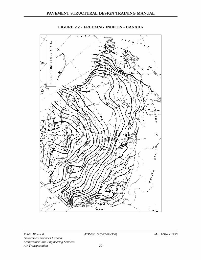
Freezing and thawing indices for existing airports are listed in the airportpavement technical data inventory. When required for new sites, freezing andthawing indices may be calculated from meteorological temperature records, ormay be estimated from Figures 2.2 and 2.3.
Public Works & ATR-021 (AK-77-68-300) March/Mars 1995Government Services CanadaArchitectural and Engineering ServicesAir Transportation - 10 -

PAVEMEN T STRUCTURAL DESIGN TRAININ G MANUAL
2.4.2 FROST AND THA W PENETRATIONS
The depth of frost penetration into ground surfaces is avariable of interest in anumber of engineering design situations. Analytical methods are available for thecalculation of frost penetration, but these methods require extensive data onsubsurface soil characteristics. With a knowledge of site air freezing index only,approximate values may be estimated from Figures 2.4 to 2.6.
The data in Figures 2.4 to 2.6 resulted from a program of measuring frostpenetrations at a number of Canadian airports. Figure 2.4 for snow cleared asphaltsurfaced pavementsshowsmaximum frost penetration recorded, plotted against airfreezing index at the site for the winter season in which the measurements weremade. Figure 2.5 is asimilar plot for snow cleared concrete surfaced pavements.
The penetration of frost in pavements actually depends on pavement surfacetemperatures which are slightly higher than air temperatures on the average. Forthis reason, penetration does not occur until air freezing index reaches acertainminimum value. For this same reason, frost penetration in concrete surfacedpavements is slightly higher than in asphalt surfaced pavements due to the effectof colour on radiation absorption.
Figure 2.6 shows frost penetration versus air freezing index for snow coverednatural ground surfaces. For this surface condition, frost penetrations are highlyvariable because they depend on the depth of snow cover, and on when the snowarrives relative to the start of freezing temperatures. Although frost penetrationsare highly variable for this surface condition, a maximum potential value can beidentified in Figure 2.6 which corresponds to the case of littl e or no snow cover.This maximum potential value is useful when considering burial depths for suchinstallations as water or drainage pipe which must be protected from frost.
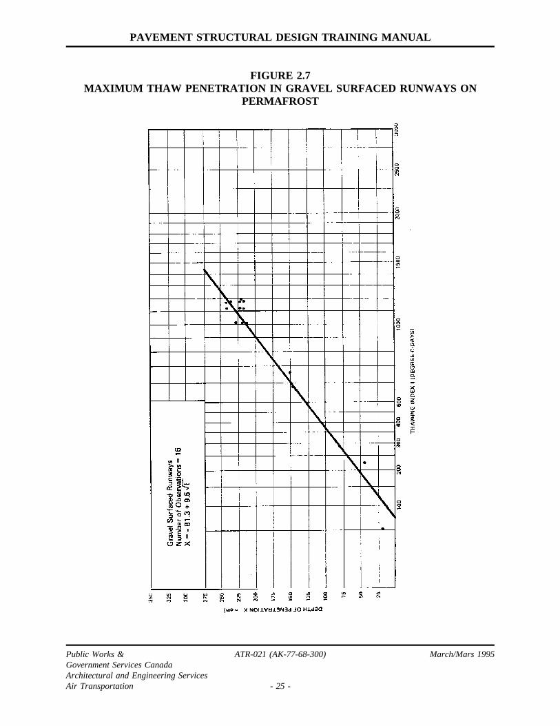
While frost penetration is of interest in seasonal frost zones, the correspondingvariable of interest in permafrost areas is the depth of thaw which occurs duringsummer. Figures 2.7 and 2.8 give some data on measured thaw penetration versusair thawing index, for gravel surfaced pavements and for natural ground surfacesrespectively.
2.4.3 FROST PROTECTIO N REQUIREMENTS
The penetration of frost into pavement subgrades can have two major detrimentaleffects. If the subgrade soil is frost susceptible and water is present, frost
Public Works & ATR-021 (AK-77-68-300) March/Mars 1995Government Services CanadaArchitectural and Engineering ServicesAir Transportation - 11 -
PAVEMENT STRUCTURAL DESIGN TRAINING MANUAL
2.4.3 FROST PROTECTION REQUIREMENTS (CONT’D)
penetration will induce ice lensing in the subgrade with subsequent frost heavingand development of roughness at the pavement surface. When this ice meltsduring spring thaw, the excess water and loss of density combine to decreasesubgrade and pavement bearing strength.
Figure 2.9 gives the minimum depth of pavement structure to attenuatethe effectsof frost heave. This minimum depth of pavement structure is a function of the siteaverage annual air freezing index calculated over a 10-30 year period. Acomparison with Figures 2.4 and 2.5 shows that the protection provided comparedto depth of frost penetration varies with the severity of freezing conditions. Inclimates with a low freezing index, the minimum pavement thickness required forfrost protection corresponds to the full depth of average frost penetration; in coldclimates, the protection requirement corresponds to roughly one-thirdof frostpenetration.
The following guidelines apply to the incorporation of frost protectionrequirements into the design of a pavement structure subject to subgrade frostpenetration:
(i) frost protection should generally be provided for pavements with pavedsurfaces constructed on frost susceptible subgrades;
(ii) frost protection is not required for pavements with unbound surfaces suchas gravel, when surface irregularities caused by frost heave can readily becorrected by regrading;
(iii) frost protection is not required for pavements constructed on non-frostsusceptible subgrade soils. Gravel and sands with less than 10 percentpassing the 0.075 mm sieve are considered non-frost susceptible;
(iv) frost protection requirements may be waived under a number of specialcircumstances:
(1) the pavement structure is to be a temporary facility;
(2) stage construction is contemplated;
(3) the pavement is for an infrequently travelled road and a low qualitystructure can be tolerated.
The pavement frost protection requirements given in Figure 2.9 are largely
Public Works & ATR-021 (AK-77-68-300) March/Mars 1995Government Services CanadaArchitectural and Engineering ServicesAir Transportation - 12 -

PAVEMENT STRUCTURAL DESIGN TRAINING MANUAL
2.4.3 FROST PROTECTION REQUIREMENTS (CONT’D)
empirical in nature. Experience has shown that when combined with adequatesubsurface drainage, they will satisfactorily attenuate frost heave effects in mostsituations.
Standard frost protection requirements are not sufficient to prevent excessivedifferential frost heaving when pockets of highly frost susceptible soil exist in anotherwise non-frost susceptible subgrade. Special measures are required for thissituation; usually excavation of the frost susceptible pockets to the depth of frostpenetration or to 1.20 m below the finished pavement surface (whichever is less)and replacement with non-frost susceptible material is required. Also, largeboulders embedded in a matrix of fine soils can be raised by frost action to createa bump at the pavement surface. Such boulders should be removed duringconstruction if they are found within the top 0.5 m of subgrade.
Public Works & ATR-021 (AK-77-68-300) March/Mars 1995Government Services CanadaArchitectural and Engineering ServicesAir Transportation - 13 -

PAVEMENT STRUCTURAL DESIGN TRAINING MANUAL
TA
BLE
2.1
-S
TA
ND
AR
DG
EA
RLO
AD
ING
S
ST
AN
DA
RD
GE
AR
LOA
DR
AT
ING
CH
AR
AC
TE
RIS
TIC
SO
FS
TA
ND
AR
DG
EA
RLO
AD
ING
S
SIN
GLE
WH
EE
LG
EA
RD
UA
LW
HE
EL
GE
AR
DU
AL
TA
ND
EM
GE
AR
Gea
rLo
ad(k
N)
Tire
Pre
ssur
e(M
Pa)
Gea
rLo
ad(k
N)
Tire
Pre
ssur
e(M
Pa)
Dua
lTire
Spa
cing
(cm
)
Gea
rLo
ad(k
N)
Tire
Pre
ssur
e(M
Pa)
Dua
ltan
dem
Tire
Spa
cing
(cm
)
120
0.30
230
0.35
345
0.40
460
0.45
800.
5050
580
0.50
110
0.60
55
611
00.
5513
00.
6560
714
00.
6017
00.
7065
822
00.
8570
929
01.
0575
440
1.10
65x1
15
1040
01.
1590
660
1.20
90x1
50
1190
01.
5511
0x16
5
1211
201.
8011
5x16
5
Public Works& ATR-021(AK-77-68-300) March/Mars1995GovernmentServicesCanadaArchitecturaland EngineeringServicesAir Transportation - 14 -

PAVEMENT STRUCTURAL DESIGN TRAINING MANUAL
TABLE 2.2 - AIRCRAFT CORRESPONDING TO STANDARD GEAR LOADINGS
S.G.L. Aircraft S.G.L. Aircraft
1 Piper Apache/AztecCessna Cutlass/SkylaneBeech Bonanza/BaronDHC2 Beaver
7 DC-4BAE-146-100Canadair CL699, 601
2 Beech King Air 90 Srs.Cessna 421 Golden EagleDHC6 Twin Otter
8 DC-9-15DC-6, 6BGulfstream II, IIIArgosy A W650BAE-146-200
3 Cessna Citation ISwearingen Metro/MerlinPiper Cheyenne III
9 BAC-111-500DC-9-21, 32Hercules C130
4 DC 3DHC8 Dash 8Gates Learjet 55, 56
10 B707-120BB737-200/300B767-200DC-7L1049 Super Constellation
5 Gulfstream G159F27HS748Dart Herald
11 B-747-100DC-10-20B707 320/420Airbus A-300VC-10-1100, 1150 Super
6 Convair 580/640Canadair CL215Dassault Falcon 50
12 ConcordeB-747-200DC-10-10, 30, 40L-1011-100, 200, 500B727-200DC-8-62, 63, 72, 73
Note: Listing above is for selected aircraft when at maximum operating weight and tire pressure.For other aircraft and aircraft operating at reduced operating weights and tire pressures,see AK-77-68-500, AK-67-09-140 or AK-68-30.
Public Works & ATR-021 (AK-77-68-300) March/Mars 1995Government Services CanadaArchitectural and Engineering ServicesAir Transportation - 15 -

PAVEMENT STRUCTURAL DESIGN TRAINING MANUAL
TABLE 2.3 - GROUND VEHICLE LOADING CHARACTERISTICS
Wheel Spacing
VehicleGross
Weight(kN)
GearLoad(kN)
Dual(cm)
Tandem(cm)
TirePressure(MPa)
VehicleLoadingGroup
EMERGENCYSmall FoamCrash Rescue1000 gal. Foam2000 gal. Foam
73.965.8169.0287.6
23.618.559.277.7
32---
--
142-
0.380.310.620.62
1124
MAINTENANCESmall Snow-plowLg. Snow-plow7200 Snow BlowerSnow Blast BlowerSpreader Truck
92.1109.4126.8151.2276.0
27.832.537.840.8106.6
----
33
----
142
0.590.590.690.590.69
22223
FUEL TANKERSImperial 7000
800095001100012500
Petrofina 12000Shell 4500
71001160015000
Standard 350014000
329.2400.3415.9
600.5542.9249.1378.1511.6582.7
640.5
93.688.8109.6111.2118.082.4100.0111.273.6133.2
77.8146.8
33333036303638413633
2836
132137122130122122
--
119127
-132
0.620.690.550.550.620.590.620.620.480.69
0.550.62
3333324424
34
OTHERSPlanematePass CarTransport Truck
Front axleSingle axleTandem axleTriple axle
361.6Var.
(axle group)53.497.6177.6266.4
90.4Var.
26.748.888.8133.2
--
-323030
--
--
180244+488
0.48Var.
0.700.700.700.70
41
3333
TOW TRACTORSLectra Haul T150International T180F
T225SLT300SLT300SLT500ST800ST800S
747.3
114.8142.3218.0177.9489.3689.5520.4
186.8
28.735.654.544.5122.3172.4130.1
-
-------
-
-------
1.03
0.520.520.760.620.720.970.72
4
444
Public Works & ATR-021 (AK-77-68-300) March/Mars 1995Government Services CanadaArchitectural and Engineering ServicesAir Transportation - 16 -

PAVEMENT STRUCTURAL DESIGN TRAINING MANUAL
TABLE 2.4 - TYPICAL SUBGRADE BEARING STRENGTHS
Subgrade Soil TypeUsualSpring
Reduction% *
Subgrade Bearing Strength (kN)
FallRange
Design Value
Fall Spring
GW - well-graded gravel 0 290-400 290 290
GP - poorly graded gravel 10 180-335 220 200
GM - gravel with silty fines 25 135-335 180 135
GC - gravel with clay fines 25 110-245 145 110
SW - well-graded sand 10 135-335 180 160
SP - poorly graded sand 20 110-200 135 110
SM - sand with silty fines 45 95-190 120 65
SC - sand with clay fines 25 65-155 85 65
ML - silt with low liquid limit 50 90-180 110 55
CL - clay with low liquid limit 25 65-135 85 65
MH - silt with high liquid limit 50 25-90 40 20
CH - clay with high liquid limit 45 25-90 55 30
* Note: When the water table is within 1 m of thepavement surface, the % spring reduction factorshould be increased by 10% for each soil type except GW and GP.
Public Works & ATR-021 (AK-77-68-300) March/Mars 1995Government Services CanadaArchitectural and Engineering ServicesAir Transportation - 17 -

PAVEMENT STRUCTURAL DESIGN TRAINING MANUAL
TABLE 2.5 - EXAMPLE FREEZING INDEX CALCULATION
Region: Site:
Month November/78 December/78 January/79 February/79 March/79 April/79
DayDailyTemp
IndexCount
DailyTemp
IndexCount
DailyTemp
IndexCount
DailyTemp
IndexCount
DailyTemp
IndexCount
DailyTemp
IndexCount
1 +5 0 -8 58 -7 285 -19 600 -8 928 -8 1131
2 +4 0 -10 68 -4 289 -18 618 -7 935 -5 1136
3 +6 0 -6 74 -6 295 -18 636 -7 942 -1 1137
4 +6 0 -4 78 -8 303 -15 651 -9 951 -2 1139
5 +8 0 -3 81 -9 312 -15 666 -8 959 0 1139
6 +7 0 -4 85 -12 324 -15 681 -11 970 -1 1140
7 +8 0 -8 93 -8 332 -12 693 -12 982 -1 1141
8 +10 0 -10 103 -5 337 -15 708 -8 990 0 1141
9 +5 0 -12 115 -3 340 -11 719 -7 997 0 1141
10 +3 0 -12 127 -1 341 -10 729 -6 1009 +1 1140
11 0 0 -12 139 +2 339 -14 743 -6 1015 0 1140
12 -1 1 -11 150 +4 335 -13 756 -4 1019 +1 1139
13 +1 0 -8 158 +3 332 -12 768 -6 1025 -1 1140
14 +1 0 -4 162 +2 330 -14 782 -5 1030 +1 1139
15 -1 1 -2 164 +1 329 -11 793 -7 1037 +1 1138
16 -1 2 -4 168 -2 331 -9 802 -5 1042 +2 1136
17 -2 4 -6 174 -4 335 -12 814 -4 1046 0 1136
18 0 4 -6 180 -8 343 -13 827 -3 1049 +2 1134
19 +1 3 -5 185 -10 353 -10 837 -6 1055 +3 1131
20 0 3 -3 188 -14 367 -7 844 -8 1063 +1 1130
21 -1 4 -3 191 -18 385 -8 852 -7 1070 +2 1128
22 -3 7 -5 196 -22 407 -10 862 -6 1077 +3 1125
23 -3 10 -8 204 -19 426 -11 873 -5 1082 +2 1123
24 -6 16 -9 213 -18 444 -8 881 -4 1086
25 -8 24 -9 222 -15 459 -9 890 -3 1089
26 -4 28 -10 232 -15 474 -10 900 -8 1097
27 -4 32 -8 240 -18 492 -9 909 -5 1102
28 -5 37 -8 248 -20 512 -11 920 -3 1105
29 -6 43 -9 257 -23 535 -3 1108
30 -7 50 -10 267 -26 561 -7 1115
31 -11 278 -20 581 -8 1123
Freezing Index for 1978/79 Freezing Season - 1141°C - Days
Public Works & ATR-021 (AK-77-68-300) March/Mars 1995Government Services CanadaArchitectural and Engineering ServicesAir Transportation - 18 -

PAVEMENT STRUCTURAL DESIGN TRAINING MANUAL
FIGURE 2.1 - SPRING REDUCTION FACTOR
Public Works & ATR-021 (AK-77-68-300) March/Mars 1995Government Services CanadaArchitectural and Engineering ServicesAir Transportation - 19 -
PAVEMENT STRUCTURAL DESIGN TRAINING MANUAL
FIGURE 2.2 - FREEZING INDICES - CANADA
Public Works & ATR-021 (AK-77-68-300) March/Mars 1995Government Services CanadaArchitectural and Engineering ServicesAir Transportation - 20 -

PAVEMENT STRUCTURAL DESIGN TRAINING MANUAL
FIGURE 2.3 - THAWING INDICES - CANADA
Public Works & ATR-021 (AK-77-68-300) March/Mars 1995Government Services CanadaArchitectural and Engineering ServicesAir Transportation - 21 -

PAVEMENT STRUCTURAL DESIGN TRAINING MANUAL
FIGURE 2.4MAXIMUM FROST PENETRATION IN ASPHALT SURFACED PAVEMENTS
Public Works & ATR-021 (AK-77-68-300) March/Mars 1995Government Services CanadaArchitectural and Engineering ServicesAir Transportation - 22 -

PAVEMENT STRUCTURAL DESIGN TRAINING MANUAL
FIGURE 2.5MAXIMUM FROST PENETRATION IN P.C.C. SURFACED PAVEMENTS
Public Works & ATR-021 (AK-77-68-300) March/Mars 1995Government Services CanadaArchitectural and Engineering ServicesAir Transportation - 23 -

PAVEMENT STRUCTURAL DESIGN TRAINING MANUAL
FIGURE 2.6MAXIMUM FROST PENETRATION IN UNDISTURBED SNOW COVERED AREAS
Public Works & ATR-021 (AK-77-68-300) March/Mars 1995Government Services CanadaArchitectural and Engineering ServicesAir Transportation - 24 -
PAVEMENT STRUCTURAL DESIGN TRAINING MANUAL
FIGURE 2.7MAXIMUM THAW PENETRATION IN GRAVEL SURFACED RUNWAYS ON
PERMAFROST
Public Works & ATR-021 (AK-77-68-300) March/Mars 1995Government Services CanadaArchitectural and Engineering ServicesAir Transportation - 25 -

PAVEMEN T STRUCTURAL DESIGN TRAININ G MANUAL
FIGURE 2.8MAXIMU M THA W PENETRATIO N IN UNDISTURBED PERMAFROST AREAS
Public Works & ATR-021 (AK-77-68-300) March/Mars 1995Government Services CanadaArchitectural and Engineering ServicesAir Transportation - 26 -

PAVEMENT STRUCTURAL DESIGN TRAINING MANUAL
FIGURE 2.9MINIMUM PAVEMENT THICKNESS FOR FROST PROTECTION
Public Works & ATR-021 (AK-77-68-300) March/Mars 1995Government Services CanadaArchitectural and Engineering ServicesAir Transportation - 27 -

PAVEMENT STRUCTURAL DESIGN TRAINING MANUAL
3.0 STRUCTURAL DESIGN THEORY
3.1 DESIGN APPROACHES
A flexible pavement supports traffic by distributing the traffic loads to the subgrade. Thedesign approach for these structures is to provide a thickness of pavement which willlimit loads transmitted to the subgrade to acceptable levels.
A rigid pavement utilizes the flexural strength of a Portland cement concrete slab for thesupport of traffic loads. Structural design is based on providing a thickness of slabsufficient to limit flexural stresses to below failure limits.
This Chapter outlines methods of determining flexible and rigid pavement thicknesses tomeet these objectives. Thickness requirements for the separate pavement layers aredetailed in Chapter 4.
3.2 FLEXIBLE PAVEMENTS
3.2.1 PLATE LOAD TESTING
Plate load testing consists of applying a load to a pavement through a rigidcircular plate and measuring the deflection produced by this load. Starting in 1945and extending over several years, a major testing program was carried out atCanadian airports utilizing this test procedure. Current structural design proceduresfor flexible pavements are based on plate load relationships derived from thisprogram.
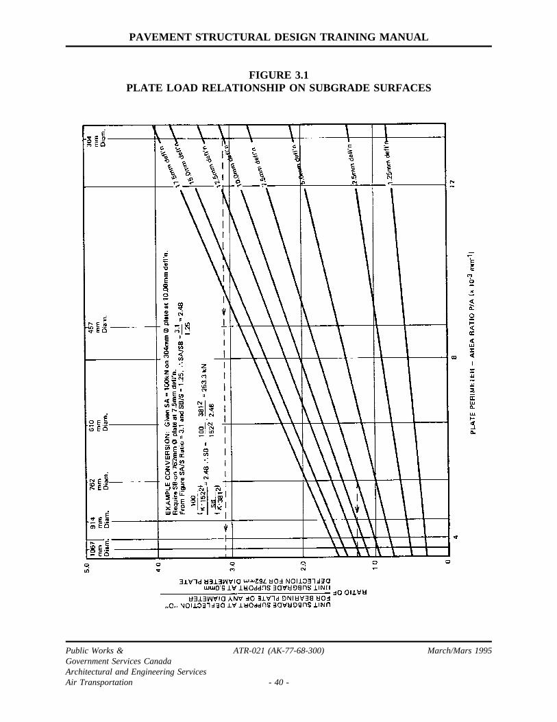
3.2.2 PLATE LOAD RELATIONSHIP ON SUBGRADE SURFACES
The plate load supported on a pavement subgrade depends on the following threemeasurement parameters:
- the deflection at which the load is measured;
- the size of the measuring plate;
Public Works & ATR-021 (AK-77-68-300) March/Mars 1995Government Services CanadaArchitectural and Engineering ServicesAir Transportation - 28 -

PAVEMENT STRUCTURAL DESIGN TRAINING MANUAL
3.2.2 PLATE LOAD RELATIONSHIP ON SUBGRADE SURFACES(CONT’D)
- the number of load applications.
Whenever a plate bearing value (kN) is quoted, values must also be given for thethree test parameters associated with its measurement.
Figure 3.1 gives the average relationship between loads measured on a subgradesurface using test plates of different sizes, and at different deflections. If asubgrade plate bearing value is available measured with a particular plate size andat a given deflection, Figure 3.1 may be used to estimate the plate bearing valuewhich would be measured if the measurement is made using a different plate size,or at a different deflection. An example of this conversion process is shown withFigure 3.1.
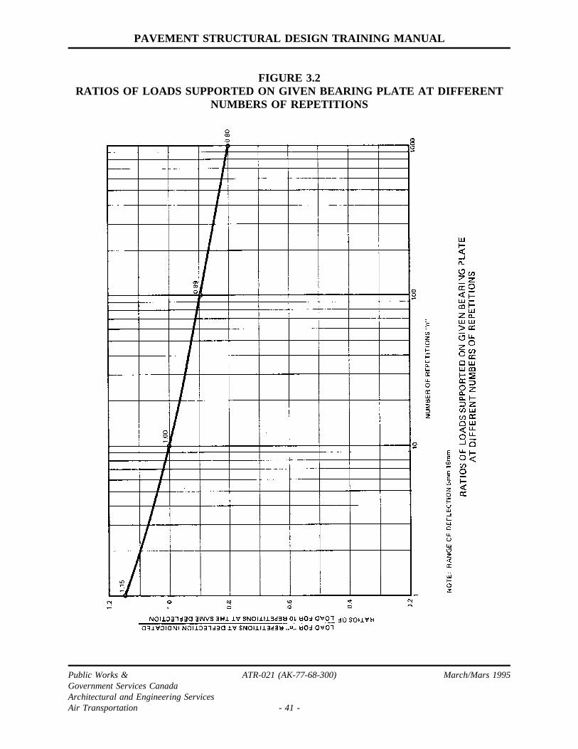
Plate bearing values also vary with the number of load applications, and testresults show that the accumulated deflection under a given load increases linearlywith the log of the number of load applications. Conversely, for a givendeflection, the plate bearing value will decrease with the number of loadapplications, and Figure 3.2 gives an average relationship between these twovariables.
3.2.3 PAVEMENT SURFACE VS SUBGRADE LOAD
If a pavement of granular base material is placed over a subgrade, the followingequation relates plate bearing values measured at the surface of the pavement andat the surface of the subgrade:
(Eq 3.1)
where P = plate bearing value measured on the pavement surface (kN)S = plate bearing value measured on the subgrade surface (kN)t = thickness of the granular pavement (cm)K = a variable dependent on the size of bearing plate being used, as
given in Figure 3.3.
Public Works & ATR-021 (AK-77-68-300) March/Mars 1995Government Services CanadaArchitectural and Engineering ServicesAir Transportation - 29 -

PAVEMENT STRUCTURAL DESIGN TRAINING MANUAL
3.2.3 PAVEMENT SURFACE VS SUBGRADE LOAD (CONT’D)
Eq. (3.1) is valid only when P and S are measured using the same size of bearingplate, at the same deflection and at the same number of load applications.
The derivation of Eq. (3.1) is outlined in AppendixB. Asa mathematical modelrelating the two plate bearing values, P and S, Eq. (3.1) contains inaccuracieswhen a pavement is very thick or when subgrade bearing strength is very high.However, the equation is sufficiently accurate for use under normal ranges ofpavement thickness and subgrade bearing strength.
It should be noted that Eq. (3.1) applies only for a pavement constructed ofgranular materials. If layers of other materials are present in the pavementstructure, such as an asphalt surfacing course, the pavement thickness must beconverted to an equivalent granular thickness.
3.2.4 EQUIVALENT GRANULAR THICKNESS
"Equivalent granular thickness" is a term frequently encountered in the design andevaluation of pavement structures. It is the common basis of comparison forflexible pavements with variable thicknesses of materials having different loaddistribution characteristics.
Table 3.1 lists granular equivalency factors for various pavement constructionmaterials. The granular equivalency factor of a material is the depth of granularmaterial in centimetres considered equivalent to one centimetre of the material onthe basis of load distribution considerations. The values listed in Table 3.1 aregenerally conservative and actual granular equivalencies are normally higher thanthe values listed.
To determine pavement equivalent granular thickness, the depth of each layer inthe pavement is multiplied by the granular equivalency factor for the material inthe layer. The sum of these converted layer thicknesses, is the pavementequivalent granular thickness.
3.2.5 EQUIVALENT SINGLE WHEEL LOAD
Design procedures for flexible pavements require that multiple-wheel loadings beconverted to an equivalent single wheel load (ESWL). For flexible pavements,equivalent single wheel load is defined as the single wheel load which produces
Public Works & ATR-021 (AK-77-68-300) March/Mars 1995Government Services CanadaArchitectural and Engineering ServicesAir Transportation - 30 -

PAVEMENT STRUCTURAL DESIGN TRAINING MANUAL
3.2.5 EQUIVALENT SINGLE WHEEL LOAD (CONT’D)
a maximum normal stress at the subgrade surface equal to that produced by themultiple-wheel loading. The contact pressure of the ESWL is equal to the contactpressure of the wheel configuration it replaces. In practice, the ESWL is notdetermined strictly in accordance with the above definition but is estimatedthrough the simplified and approximate procedure outlined below.
An equivalent single wheel load chart for a multiple wheel gear loading isillustrated in Figure 3.5. The ESWL is a function of pavement thickness. For apavement thickness less than a certain value t1, the ESWL is equal to the load onone wheel of the gear. For a pavement thickness above a value t2, the ESWL isequal to the total gear load. For a pavement thickness between tl and t2, the logof the ESWL is assumed to vary linearly with the log of pavement thickness.
The thicknesses t1 and t2 are defined as follows:
t1= half of the minimum clear distance between any two tire imprints in the gearconfiguration;
t2= twice the centre-to-centre distance between the outermost wheel and the wheelclosest to the geometric centre of the gear configuration.
The minimum clear distances and the centre-to-centre wheel distances used incalculating t1 and t2 are illustrated in Figure 3.6 for various gear configurations.In drawing a gear configuration, the imprint of a single tire is assumed to be arectangle with semi-circular ends as shown in Figure 3.6(a). The followingequations govern the dimensions of this imprint area:
(3.2)
(3.3)
(3.4)
Public Works & ATR-021 (AK-77-68-300) March/Mars 1995Government Services CanadaArchitectural and Engineering ServicesAir Transportation - 31 -
PAVEMENT STRUCTURAL DESIGN TRAINING MANUAL
3.2.5 EQUIVALENT SINGLE WHEEL LOAD (CONT’D)
where A = contact area of the tire (cm2)P = tire load (kN)Q = tire pressure (MPa)L = length of tire imprint (cm)W = width of tire imprint (cm).
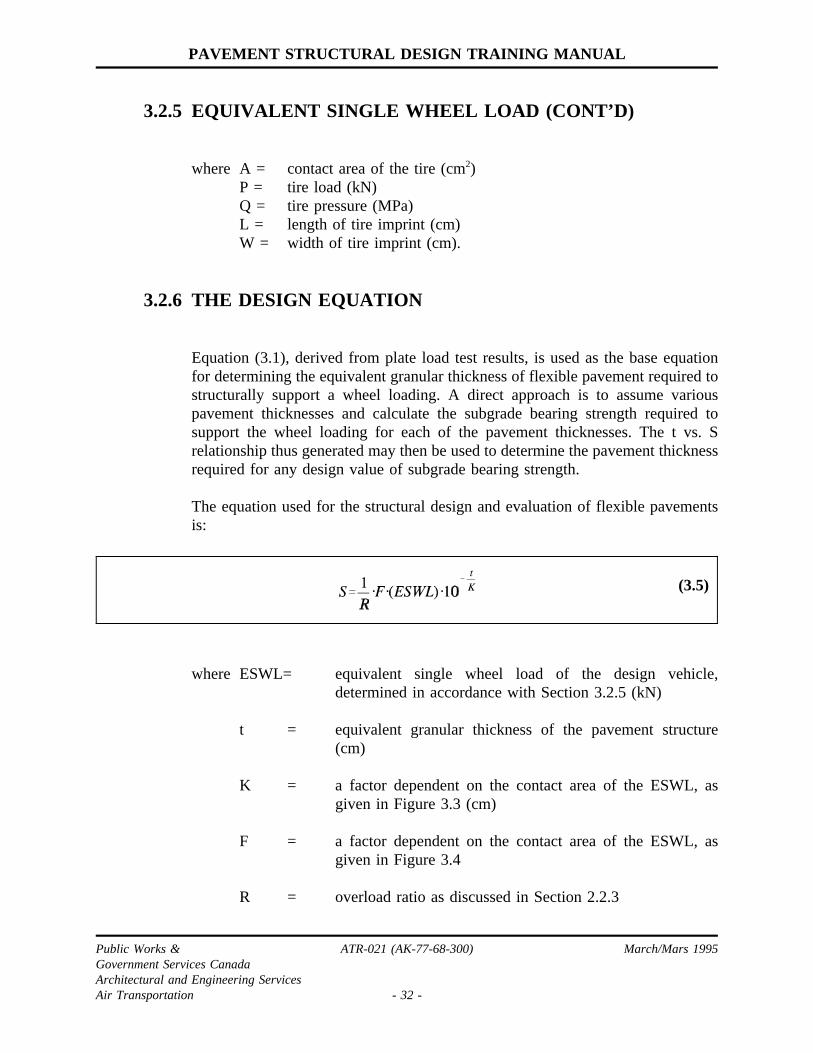
3.2.6 THE DESIGN EQUATION
Equation (3.1), derived from plate load test results, is used as the base equationfor determining the equivalent granular thickness of flexible pavement required tostructurally support a wheel loading. A direct approach is to assume variouspavement thicknesses and calculate the subgrade bearing strength required tosupport the wheel loading for each of the pavement thicknesses. The t vs. Srelationship thus generated may then be used to determine the pavement thicknessrequired for any design value of subgrade bearing strength.
The equation used for the structural design and evaluation of flexible pavementsis:
(3.5)
where ESWL= equivalent single wheel load of the design vehicle,determined in accordance with Section 3.2.5 (kN)
t = equivalent granular thickness of the pavement structure(cm)
K = a factor dependent on the contact area of the ESWL, asgiven in Figure 3.3 (cm)
F = a factor dependent on the contact area of the ESWL, asgiven in Figure 3.4
R = overload ratio as discussed in Section 2.2.3
Public Works & ATR-021 (AK-77-68-300) March/Mars 1995Government Services CanadaArchitectural and Engineering ServicesAir Transportation - 32 -

PAVEMENT STRUCTURAL DESIGN TRAINING MANUAL
3.2.6 THE DESIGN EQUATION (CONT’D)
S = subgrade bearing strength (kN) (750 mm plate, 12.5 mmdeflection, 10 rep. of loading) required to support theESWL for pavement thickness t.
Equation (3.5) is easily derived from equation (3.1) by substituting ESWL for P,and adding the factors F and R.
The factor F is included in equation (3.5) to convert the calculated subgradebearing value from a contact area equal to that of the ESWL, to the contact areaof a 750 mm diameter plate, which is the standard plate size for measuringsubgrade bearing strength. The function relating F to the ESWL contact area, asgiven in figure 3.4, is derived from the plate load relationships given in Figure3.1.
The overload ratio, R, is required when using equation (3.5) for evaluationpurposes. In the design situation, R =1.00.
3.2.7 DESIGN FOR AIRCRAFT LOADING
A flexible pavement design-evaluation chart for an aircraft gear loading isillustrated in Figure 3.7. This chart is generated using equation (3.5) as follows:
(i) assume a value of pavement equivalent granular thickness, t.
(ii) calculate the ESWL (kN) of the design aircraft gear loading as outlined inSection 3.2.5.
(iii) compute A = 10 (ESWL)/Qwhere A = contact area of ESWL (cm2)
Q = tire pressure of design aircraft (MPa)
(iv) for this contact area, A, obtain values of K and F from Figures 3.3 and 3.4respectively.
(v) with these values of ESWL, K and F, use equation (3.5) to compute thesubgrade bearing strength required for overload ratios of R = 1.00,1.25,1.50 and 2.00.
(vi) assume other values of t and repeat steps (ii) to (v) to compute
Public Works & ATR-021 (AK-77-68-300) March/Mars 1995Government Services CanadaArchitectural and Engineering ServicesAir Transportation - 33 -

PAVEMENT STRUCTURAL DESIGN TRAINING MANUAL
3.2.7 DESIGN FOR AIRCRAFT LOADING (CONT’D)
corresponding S values.
(vii) plot t vs. S curves for R values of 1.00,1.25, 1.50 and 2.00, as shown inFigure 3.7.
A computer program for these computations is given in Appendix D.
In the design situation, pavement structural thickness requirements are determinedfrom a chart similar to that illustrated in Figure 3.7 using the design value ofsubgrade bearing strength and the overload ratio R = 1.00 curve. In an evaluationsituation, an operation by the aircraft gear loading on a given pavement isevaluated by plotting the point having the pavement t and S values as co-ordinates. The location of this point on the chart with respect to the overloadcurves indicates whether the operation falls into the unrestricted, limited, marginalor emergency use only category.
3.2.8 DESIGN FOR GROUND VEHICLES
For roads and carparks, subgrade bearing strength was originally defined in termsof the load supported on a 305 mm diameter plate, 5 mm deflection, 10 repetitionsof loading. However, mathematically, it can be shown that this measure isequivalent to using design equation (3.5), together with a value of R = 0.625.
Consequently, roads and carparks may be designed using the procedures outlinedabove, the applicable ground vehicle design loading and a value of R = 0.625.This value of overload ratio R, produces a higher thickness design requirement forroad and carpark pavement than for aircraft pavements. In pavement fatigue terms,this higher design requirement reflects the greater number of load repetitionsexpected on roads, as compared to aircraft pavements. In some situations, whereit is known that a road will be subject to infrequent traffic, the pavement may bedesigned using a value of R = 1.00, corresponding to aircraft pavement designrequirements
Public Works & ATR-021 (AK-77-68-300) March/Mars 1995Government Services CanadaArchitectural and Engineering ServicesAir Transportation - 34 -

PAVEMENT STRUCTURAL DESIGN TRAINING MANUAL
3.3 RIGID PAVEMENTS
3.3.1 STRESS ANALYSIS OF CONCRETE SLABS
The stress analysis of a concrete pavement slab is based on the theory of thinplates. The following assumptions are made relative to the pavement slab andloading conditions:
(i) the slab consists of a homogeneous, isotropic and elastic material.
(ii) the slab is of uniform thickness, and the range of relative thickness is suchthat the ordinary theory of thin plates may be applied.
(iii) the load is applied normal to the face of the slab, and is remote from anedge.
(iv) the reaction of the base beneath the slab occurs normal to the slab, and isdirectly proportional to the slab deflection.
With these assumptions, and for a concentrated load, the following differentialequation applies for all of the slab except the point of application of theconcentrated load.
(3.6)
Where D is the flexural rigidity of the slab,σ2 is the Laplace differential operator,ω is the slab deflection andk is the proportionality constant between slabdeflection and base reaction. Appendix C provides a more detailed description ofthe notation involved in Eq. (3.6), and outlines the solution of this differentialequation for various loading conditions.
To apply the equations resulting from the solution of Eq. (3.6), values must firstbe determined for a number of variables. The following values are assumed forthe elastic properties of the concrete:
elastic modulus E = 27,580 MPaPoissons ratio µ = 0.15
Public Works & ATR-021 (AK-77-68-300) March/Mars 1995Government Services CanadaArchitectural and Engineering ServicesAir Transportation - 35 -

PAVEMENT STRUCTURAL DESIGN TRAINING MANUAL
3.3.1 STRESS ANALYSIS OF CONCRETE SLABS (CONT’D)
The determination of the bearing modulusk, and allowable flexural stresses arediscussed below.
3.3.2 BEARING MODULUS
In Eq. (3.6), the variablek is the proportionality constant between slab deflectionand reaction pressure generated on the bottom of the slab by the base course. Thisvariable is called the bearing modulus.
The bearing modulus,k, is measured using a 750 mm diameter plate and a singleapplication of load. The bearing plate is loaded to produce a deflection of1.25 mm, and the plate pressure in kPa is then divided by the deflection, 1.25 mm,to calculate bearing modulus in units of MPa/m.
In practice, bearing modulus is normally not measured directly but is estimatedfrom a design value of subgrade bearing strength, and the thickness of base andsub-base placed between the subgrade and the concrete slab. The equation usedfor this purpose is:
(3.10)
where k = bearing modulus (MPa/m)S = subgrade bearing strength (kN)t = equivalent granular thickness of base and sub-base (cm)
This equation is plotted in Figure 3.8.
Equation (3.10) may be derived from the plate load test relationships given inSections 3.2.2 and 3.2.3. The selection of a design value for subgrade bearingstrength is discussed in Section 2.3.2.
For the design of new concrete pavement structures, the maximum value ofbearing modulus is limited to 135 MPa/m. This limitation is placed because veryhigh values of bearing modulus cannot always be relied upon due to suchoccurrences as differential subgrade settlement, frost heaving, and slab curlingcaused by thermal effects.
Public Works & ATR-021 (AK-77-68-300) March/Mars 1995Government Services CanadaArchitectural and Engineering ServicesAir Transportation - 36 -

PAVEMENT STRUCTURAL DESIGN TRAINING MANUAL
3.3.3 FLEXURAL STRENGTH AND ALLOWABLE STRESSES
Considerations with respect to concrete flexural strength and allowable stresses arean important element in the design and evaluation of concrete pavements.Concrete flexural strength is a function of age as indicated in Figure 3.9. Forconstruction purposes, the strength of a concrete mix is normally specified interms of a 28 day curing period but as it ages, the concrete will continue to slowlygain strength at a decreasing rate.
Construction specifications and field quality control should ensure an average 28day flexural strength not less than 4.0 MPa. With good quality aggregates andproper mix design, 28 day flexural strengths in the order of 4.5 to 5.0 MPa are notuncommon. After a few years of curing, the flexural strength of the concrete willusually be unknown, but values of 6.0 to 6.5 MPa are possible.
The selection of allowable stresses is influenced by fatigue considerations. Failureoccurs with one application of load producing a stress equal to the flexuralstrength. Under repeated load applications, however, failure stress decreaseslinearly with the log of the number of load applications. For a very large, orunrestricted, number of load applications, the allowable stress should be keptbelow one-half of the flexural strength.
Based on these considerations, the following allowable stresses are normally usedin the design and evaluation of concrete pavements.
Criteria for: Overload Ratio Allowable FlexuralStress (MPa)
Design 1.00 2.75Unrestricted Operations < 1. 25 3.5Limited Operations 1. 25 - 1. 50 3.5 - 4.1Marginal Operations 1.50 - 2.00 4.1 - 5.5Emergency Use Only > 2.00 5.5
3.3.4 DESIGN FOR AIRCRAFT LOADING
Stress analysis of a concrete slab, based on the equations given in Appendix C isusually performed by computer. A computer program for this purpose is given inAppendix E.
Public Works & ATR-021 (AK-77-68-300) March/Mars 1995Government Services CanadaArchitectural and Engineering ServicesAir Transportation - 37 -

PAVEMENT STRUCTURAL DESIGN TRAINING MANUAL
3.3.4 DESIGN FOR AIRCRAFT LOADING (CONT’D)
The output of the computer program given in Appendix E may be used to preparea design-evaluation chart for a particular aircraft gear loading, as shown in Figure3.10 where slab thickness is given as a function of bearing modulus for four stresslevels: 2.75, 3.5, 4.1 and 5.5 MPa. In the design situation, slab thicknessrequirements may be determined from the 2.75 MPa stress curve after obtaininga design value for bearing modulus in accordance with Section 3.3.2. In anevaluation situation, an operation by the aircraft gear loading on a given pavementis evaluated by plotting the point having the pavement h and k values. Thelocation of this point on the chart relative to the overload curves indicates whetherthe operation falls into the unrestricted, limited, marginal or emergency use onlycategory.
3.4 COMPOSITE DESIGN-EVALUATION CHARTS
Design-evaluation charts of the type shown in Figures 3.7 and 3.10 are limited toonly one aircraft operating weight. A series of these individual weight charts mustbe prepared to provide design/evaluation capability over the entire range of anaircraft’s operating weights. To reduce the number of charts required, such a seriesof individual weight charts can be consolidated into one composite design-evaluation chart of the type shown in Figure 3.11 for flexible pavements andFigure 3.12 for rigid pavements.
The composite design-evaluation chart is constructed by first arbitrarily drawinga diagonal reference line, running from bottom left to top right, between the upperand lower horizontal scales. This diagonal is assigned as the reference line for theaircraft at its maximum take-off weight. The information from the individualweight chart for maximum take-off weight is then transposed onto the compositechart to establish the position of the curves reflecting requirements for design,unrestricted, limited, marginal and emergency use only operations. When theposition of these curves are established, information from the other individualweight charts may then be incorporated to determine the position of diagonalreference lines for other aircraft operating weights.
Composite design-evaluation charts for present day aircraft are published in AK-68-16 "Pavement Design-Evaluation Charts for Selected Aircraft".
Public Works & ATR-021 (AK-77-68-300) March/Mars 1995Government Services CanadaArchitectural and Engineering ServicesAir Transportation - 38 -

PAVEMENT STRUCTURAL DESIGN TRAINING MANUAL
TABLE 3.1 - GRANULAR EQUIVALENCY FACTORS
Pavement Material
GranularEquivalency
Factor
Selected granular sub-base 1
Crushed gravel or stone base 1
Waterbound macadam base 1 ½
Bituminous stabilized base 1 ½
Cement stabilized base 2
Asphaltic concrete (good condition) 2
Asphaltic concrete (poor condition) 1 ½
Portland cement concrete (good condition) 3
Portland cement concrete (fair condition) 2 ½
Portland cement concrete (poor condition) 2
NOTE: The equivalent granular thickness of a layer iscalculated by multiplying the layer thickness by thegranular equivalency factor for the material in thelayer.
Example
Given - pavement structure: 8 cm A.C. (good condition) + 25 cm base + 20 cm sub-baseProblem - to determine the equivalent granular thickness
Solution
LayerComponent
GranularEquivalency
Factor
EquivalentGranularThickness
8 cm A.C. x 2 16 cm25 cm base x 1 25 cm
20 cm sub-base x 1 20 cm61 cm
(total equivalentgranular thickness)
Public Works & ATR-021 (AK-77-68-300) March/Mars 1995Government Services CanadaArchitectural and Engineering ServicesAir Transportation - 39 -
PAVEMENT STRUCTURAL DESIGN TRAINING MANUAL
FIGURE 3.1PLATE LOAD RELATIONSHIP ON SUBGRADE SURFACES
Public Works & ATR-021 (AK-77-68-300) March/Mars 1995Government Services CanadaArchitectural and Engineering ServicesAir Transportation - 40 -
PAVEMENT STRUCTURAL DESIGN TRAINING MANUAL
FIGURE 3.2RATIOS OF LOADS SUPPORTED ON GIVEN BEARING PLATE AT DIFFERENT
NUMBERS OF REPETITIONS
Public Works & ATR-021 (AK-77-68-300) March/Mars 1995Government Services CanadaArchitectural and Engineering ServicesAir Transportation - 41 -

PAVEMENT STRUCTURAL DESIGN TRAINING MANUAL
FIGURE 3.3FLEXIBLE PAVEMENT DESIGN EQUATION - FACTOR K
Public Works & ATR-021 (AK-77-68-300) March/Mars 1995Government Services CanadaArchitectural and Engineering ServicesAir Transportation - 42 -

PAVEMENT STRUCTURAL DESIGN TRAINING MANUAL
FIGURE 3.4FLEXIBLE PAVEMENT DESIGN EQUATION - FACTOR F
Public Works & ATR-021 (AK-77-68-300) March/Mars 1995Government Services CanadaArchitectural and Engineering ServicesAir Transportation - 43 -

PAVEMENT STRUCTURAL DESIGN TRAINING MANUAL
FIGURE 3.5AIRCRAFT EQUIVALENT SINGLE WHEEL LOAD CHART
Public Works & ATR-021 (AK-77-68-300) March/Mars 1995Government Services CanadaArchitectural and Engineering ServicesAir Transportation - 44 -

PAVEMENT STRUCTURAL DESIGN TRAINING MANUAL
FIGURE 3.6DIMENSIONS USED FOR DETERMINATION OF EQUIVALENT SINGLE WHEEL
LOAD
Public Works & ATR-021 (AK-77-68-300) March/Mars 1995Government Services CanadaArchitectural and Engineering ServicesAir Transportation - 45 -

PAVEMENT STRUCTURAL DESIGN TRAINING MANUAL
FIGURE 3.7FLEXIBLE PAVEMENT DESIGN/EVALUATION CHART FOR GIVEN WEIGHT OF
AIRCRAFT
Public Works & ATR-021 (AK-77-68-300) March/Mars 1995Government Services CanadaArchitectural and Engineering ServicesAir Transportation - 46 -

PAVEMENT STRUCTURAL DESIGN TRAINING MANUAL
FIGURE 3.8 - BEARING MODULUS k AS A FUNCTION OF S AND t
Public Works & ATR-021 (AK-77-68-300) March/Mars 1995Government Services CanadaArchitectural and Engineering ServicesAir Transportation - 47 -

PAVEMENT STRUCTURAL DESIGN TRAINING MANUAL
FIGURE 3.9 - VARIATION OF CONCRETE STRENGTH WITH AGE
Public Works & ATR-021 (AK-77-68-300) March/Mars 1995Government Services CanadaArchitectural and Engineering ServicesAir Transportation - 48 -

PAVEMENT STRUCTURAL DESIGN TRAINING MANUAL
FIGURE 3.10RIGID PAVEMENT DESIGN/EVALUATION CHART
FOR A GIVEN WEIGHT OFAIRCRAFT
Public Works & ATR-021 (AK-77-68-300) March/Mars 1995Government Services CanadaArchitectural and Engineering ServicesAir Transportation - 49 -

PAVEMENT STRUCTURAL DESIGN TRAINING MANUAL
FIGURE 3.11 - FLEXIBLE PAVEMENT DESIGN AND EVALUATION CHART
Public Works & ATR-021 (AK-77-68-300) March/Mars 1995Government Services CanadaArchitectural and Engineering ServicesAir Transportation - 50 -

PAVEMENT STRUCTURAL DESIGN TRAINING MANUAL
FIGURE 3.12 - RIGID PAVEMENT DESIGN AND EVALUATION CHART
Public Works & ATR-021 (AK-77-68-300) March/Mars 1995Government Services CanadaArchitectural and Engineering ServicesAir Transportation - 51 -

PAVEMENT STRUCTURAL DESIGN TRAINING MANUAL
4.0 DESIGN STANDARDS
4.1 STANDARD LOADINGS
Standard gear loadings for pavement design were presented in Section 2.2.Application of the design theory of Chapter 3 results in the following charts forthese standard loadings.
Figure 4.1 Flexible pavement equivalent granular thickness requirements foraircraft standard gear loadings.
Figure 4.2 Rigid pavement slab thickness requirements for aircraft standardgear loadings.
Figure 4.3 Flexible pavement equivalent granular thickness requirements forground vehicle standard loadings.
4.2 AIRCRAFT PAVEMENTS
4.2.1 ASPHALT PAVEMENT THICKNESS REQUIREMENTS
The depth of asphalt pavement structure provided is the greater of the:
(i) frost protection requirement given in Section 2.4.3;
(ii) structural thickness requirement for the design standard gear loading asgiven in Figure 4.1;
(iii) minimum asphalt and base course thicknesses given in Table 4.1.
The depth of pavement structure is divided into layers of asphalt, base and sub-base in accordance with Table 4.1. Note that an asphalt surfaced pavement mustbe converted to an equivalent granular thickness to check compliance withrequirement (ii) above.
Public Works & ATR-021 (AK-77-68-300) March/Mars 1995Government Services CanadaArchitectural and Engineering ServicesAir Transportation - 52 -
PAVEMENT STRUCTURAL DESIGN TRAINING MANUAL
4.2.2 GRANULAR PAVEMENT THICKNESS REQUIREMENTS
Frost protection is not normally a requirement for granular surfaced pavement.Consequently the thickness of granular pavement need only meet the structuralthickness requirement for the design standard gear loading as given in Figure 4.1.This thickness should be divided into base and sub-base courses with the depthof base course being not less than 15 cm.
4.2.3 CONCRETE PAVEMENT THICKNESS REQUIREMENTS
The total depth of concrete pavement structure provided should be the greater ofthe:
(i) frost protection requirement given in Section 2.4.3;
(ii) slab thickness required to structurally support the design standard gearloading as given in figure 4.2, plus 15 cm of base course.
The thickness of Portland cement concrete slab required for structural support isdetermined as follows:
(1) estimate the thickness of slab required and subtract this thickness from thetotal pavement depth to give the thickness of base and sub-base courses;
(2) determine the bearing modulus, k, at the top of the base course by themethods of Section 3.3.2;
(3) determine the slab thickness required for this bearing modulus using Figure4.2;
(4) repeat these steps until the slab thickness determined in (3) is equal to thethickness estimated in (1).
The minimum thickness of concrete slab to be provided is 23 cm, and theminimum thickness of base course is 15 cm. At international airports servingheavy aircraft traffic, concrete pavements are generally provided with a 20 cmcement stabilized base course. Subbase thickness is calculated as the differencebetween total pavement thickness required and slab plus base thickness.
Public Works & ATR-021 (AK-77-68-300) March/Mars 1995Government Services CanadaArchitectural and Engineering ServicesAir Transportation - 53 -

PAVEMENT STRUCTURAL DESIGN TRAINING MANUAL
4.2.4 CONCRETE PAVEMENT JOINT AND STEEL DETAILS
Joint and reinforcement design details for aircraft concrete pavements are givenin Figures 4.4, 4.5, 4.6 and 4.7.
In general, plain concrete is used for aircraft rigid pavements without the additionof reinforcement, crack control steel, tie bars or load transfer dowelling. Theexceptions as shown in Figures 4.6 and 4.7 are the use of tie bars for smallirregular shaped panels, reinforcement steel around interior manholes andcatchbasins, and crack control steel at locations of mismatched joints.
Because plain concrete is used, joints must be placed at relatively close intervalsto avoid cracking caused by thermal expansion and contraction. Longitudinalconstruction joints and transverse contraction joints are usually located at 6 mintervals, with a construction joint along the centerline of runways and taxiways.Construction joint spacing is increased to 7.5 m on runways and taxiways servingwide-bodied aircraft to avoid the outside support gears of these aircraft trackingalong a construction joint.
The outside edge of concrete pavements is an area of concern because waterentering through the shoulder frequently causes differential heaving which resultsin a longitudinal crack along the outside bay. Outside bays adjacent to shouldersshould therefore be cut or formed to half bay width. This requirement may bedeleted if shoulders are paved to a width not less than 6 m.
4.2.5 BLAST PADS AND SHOULDERS
Figures 4.8 and 4.9 provide some design details for runway blast pads, pavedshoulders and the sealing of side drainage on unpaved shoulders.
4.2.6 DESIGN COMPATIBILITY
The design of new aircraft pavements should be compatible with the design ofexisting pavements at an airport. When a new pavement is constructed thatconstitutes an expansion of an existing pavement or traffic route, the design of thenew pavement should be compatible with the bearing strength of existingpavements which will share the same traffic.
Public Works & ATR-021 (AK-77-68-300) March/Mars 1995Government Services CanadaArchitectural and Engineering ServicesAir Transportation - 54 -

PAVEMENT STRUCTURAL DESIGN TRAINING MANUAL
4.3 ROADS AND CARPARKS
4.3.1 ASPHALT PAVEMENT THICKNESS REQUIREMENTS
The depth of asphalt pavement structure to be provided is the greater of the:
(i) frost protection requirement given in Section 2.4.3;
(ii) structural thickness requirement for the design standard loading as givenin Figure 4.3;
(iii) minimum asphalt and base course thicknesses given in Table 4.2.
The depth of pavement structure is divided into layers of asphalt, base and sub-base in accordance with Table 4.2. Note that an asphalt surfaced pavement mustbe converted to an equivalent granular thickness to check compliance withrequirement (ii) above.
4.3.2 GRANULAR PAVEMENT THICKNESS REQUIREMENTS
Frost protection is not normally a requirement for granular surfaced pavements.Consequently the thickness of granular pavement need only meet the structuralthickness requirement for the standard design loading as given in Figure 4.3. Thisthickness should be divided into base and sub-base courses with the depth of basecourse being not less than 15 cm.
4.3.3 CONCRETE PAVEMENT THICKNESS REQUIREMENTS
Rigid pavements for roads and carparks are not designed by the theory outlinedin Chapter 3; standard sections are normally used in which slab thicknesses arebased on experience. Airport access roads and carparks are usually constructedwith flexible pavements and rigid pavement designs are rarely required. If rigidpavement is being considered as an option, the design should be performedaccording to the recommendations of the Provincial Highway Department or thePortland Cement Association.
Public Works & ATR-021 (AK-77-68-300) March/Mars 1995Government Services CanadaArchitectural and Engineering ServicesAir Transportation - 55 -

PAVEMENT STRUCTURAL DESIGN TRAINING MANUAL
TABLE 4.1 - MINIMUM LAYER THICKNESS FOR FLEXIBLE AIRCRAFTPAVEMENTS
DESIGN AIRCRAFT TIRE PRESSURE
Component LayerLess than0.5 MPa
0.5 MPa to0.75 MPa
0.75 MPa to1.0 MPa
Greater than1.0 MPa
Asphalt ConcreteSurface Course(Hot-Mixed)
5.0 cm 6.5 cm 8.0 cm 10.0 cm
Crushed Gravel orCrushed StoneBase Course
15 cm 20 cm 25 cm 30 cm
Selected GranularSub-base Course
As required in addition to the asphalt and base layers toprovide:
(a) the total pavement equivalent granularthickness required for structural support.
(b) the total pavement depth required for frostprotection.
NOTES:
At grant-in-aid/small airports and other special locations, the pavement required for tirepressures below 0.4 MPa may be designed as a cold-mixed asphalt surfacing. Thefigures given for hot mix are also the minimum thickness requirements for a cold mix.
In areas of rock cut, the minimum pavement thickness shall be 15 cm of granular basecourse plus the pavement surface thickness as specified above.
Public Works & ATR-021 (AK-77-68-300) March/Mars 1995Government Services CanadaArchitectural and Engineering ServicesAir Transportation - 56 -

PA
VE
ME
NT
ST
RU
CT
UR
AL
DE
SIG
NT
RA
ININ
GM
AN
UA
L
TABLE 4.2 - MINIMUM LAYER THICKNESSES FOR GROUND VEHICLE FLEXIBLE PAVEMENTS
DesignGroup
TypicalVehicle
GearArrangement
GearLoadkN
Wheel Spacing TirePressure
MPa
MinimumPavementThicknes
RequirementsDualcm
Tandemcm
1 Local AirportsCarsLight trucks
SingleDual
Dual - Tandem
202440
-3030
--
120
0.500.500.50
6.5cm A.C.15-20cm Cr.Gr. orSt. BaseSub-base asrequired (see notebelow)
2 Regional AirportsBusesSome trucksMaintenance vehiclesSome fuel tankers
SingleDual
Dual - Tandem
405080
-4030
--
120
0.700.600.60
6.5cm A.C.20cm Cr.Gr. or St.BaseSub-base asrequired
3 National AirportsHeavy trucksFuel tankersHeavy maintenance
SingleDual
Dual - Tandem
7080120
-4030
--
130
0.700.600.70
8.0 cm A.C.25cm Cr.Gr. or St.BaseSub-base asrequired
4 International AirportsHeavy fuel tankersHeacy service
SingleDual
Dual - Tandem
100110170
-4040
--
140
0.800.700.80
8.0 cm A.C.25cm Cr.Gr. or St.BaseSub-base asrequired
Notes:
(1) For small airports with low traffic volumes, the flexible pavement minimum thickness requirements for Design Group 1 may be reduced to5cm A.C. + 15cm Cr. Gr. or St.Base.
(2) Sub-base thickness is the greater of:- thickness required to provide total pavement equivalent granular thickness for structural support; or- thickness required for frost protection.
Pu
blic
Wo
rks&
AT
R-0
21
(AK
-77
-68
-30
0)
Ma
rch/M
ars
19
95
Go
vern
me
nt
Se
rvices
Ca
na
da
Arch
itectu
rala
nd
En
gin
ee
ring
Se
rvices
Air
Tra
nsp
orta
tion
-5
7-

PAVEMENT STRUCTURAL DESIGN TRAINING MANUAL
FIGURE 4.1FLEXIBLE AIRFIELD PAVEMENT STRUCTURAL THICKNESS REQUIREMENTS
Public Works & ATR-021 (AK-77-68-300) March/Mars 1995Government Services CanadaArchitectural and Engineering ServicesAir Transportation - 58 -
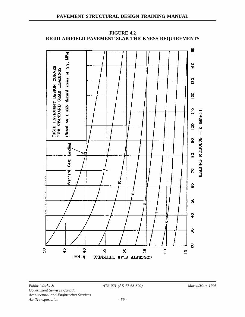
PAVEMENT STRUCTURAL DESIGN TRAINING MANUAL
FIGURE 4.2RIGID AIRFIELD PAVEMENT SLAB THICKNESS REQUIREMENTS
Public Works & ATR-021 (AK-77-68-300) March/Mars 1995Government Services CanadaArchitectural and Engineering ServicesAir Transportation - 59 -

PAVEMENT STRUCTURAL DESIGN TRAINING MANUAL
FIGURE 4.3FLEXIBLE ROAD AND CAR-PARK PAVEMENTS
STRUCTURAL THICKNESS REQUIREMENTS
Public Works & ATR-021 (AK-77-68-300) March/Mars 1995Government Services CanadaArchitectural and Engineering ServicesAir Transportation - 60 -

PAVEMENT STRUCTURAL DESIGN TRAINING MANUAL
FIGURE 4.4CONCRETE JOINTS - CONSTRUCTION DETAIL NO. 1
Public Works & ATR-021 (AK-77-68-300) March/Mars 1995Government Services CanadaArchitectural and Engineering ServicesAir Transportation - 61 -

PAVEMENT STRUCTURAL DESIGN TRAINING MANUAL
FIGURE 4.5CONCRETE JOINTS - CONSTRUCTION DETAILS NO. 2
Public Works & ATR-021 (AK-77-68-300) March/Mars 1995Government Services CanadaArchitectural and Engineering ServicesAir Transportation - 62 -

PAVEMENT STRUCTURAL DESIGN TRAINING MANUAL
FIGURE 4.5 (CONT’D)CONCRETE JOINTS - CONSTRUCTION DETAILS NO. 2
Public Works & ATR-021 (AK-77-68-300) March/Mars 1995Government Services CanadaArchitectural and Engineering ServicesAir Transportation - 63 -

PAVEMENT STRUCTURAL DESIGN TRAINING MANUAL
FIGURE 4.6CONCRETE JOINTS - CONSTRUCTION DETAILS NO. 3
Public Works & ATR-021 (AK-77-68-300) March/Mars 1995Government Services CanadaArchitectural and Engineering ServicesAir Transportation - 64 -

PAVEMENT STRUCTURAL DESIGN TRAINING MANUAL
FIGURE 4.7CONCRETE SLAB REINFORCEMENT AROUND INTERIOR MANHOLES
AND CATCH BASINS
Public Works & ATR-021 (AK-77-68-300) March/Mars 1995Government Services CanadaArchitectural and Engineering ServicesAir Transportation - 65 -

PAVEMENT STRUCTURAL DESIGN TRAINING MANUAL
FIGURE 4.8STANDARD DETAILS FOR AIRFIELD PAVEMENT SHOULDERS
Public Works & ATR-021 (AK-77-68-300) March/Mars 1995Government Services CanadaArchitectural and Engineering ServicesAir Transportation - 66 -

PAVEMENT STRUCTURAL DESIGN TRAINING MANUAL
FIGURE 4.9TYPICAL SECTIONS FOR PAVED SHOULDERS AND BLAST PADS
Public Works & ATR-021 (AK-77-68-300) March/Mars 1995Government Services CanadaArchitectural and Engineering ServicesAir Transportation - 67 -

PAVEMENT STRUCTURAL DESIGN TRAINING MANUAL
5.0 PAVEMENT RESTORATION
5.1 ASPHALT PAVEMENTS
5.1.1 RESTORATION ALTERNATIVES
Alternatives that may be considered for the restoration of asphalt surfaces includethe following:
(i) Recycling - central plant hot mixed recycling of the existing asphaltsurface or portion thereof. When bearing strength increases are notrequired, recycling may be the low cost option, although disruption totraffic may be greater than in the case of an overlay.
(ii) Overlay - overlays result in the least disruption to traffic. An overlay is themost usual method of restoration when strengthening is required and maybe cost competitive with recycling in other cases.
(iii) Reconstruction - reconstruction is significantly more costly than otherrestoration methods and is usually undertaken only when subsurfacedeficiencies exist, and the restored pavement will not perform satisfactorilyunless these deficiencies are corrected. ln some situations, reconstructionmay also be required because of grade restrictions.
(iv) Seal Coat - seal coats should be considered as a possible restorationmethod only for low volume roads (AADT < 2000). Slurry seals may beconsidered as a temporary (1 to 3 years) corrective measure for airfieldpavements when sufficient funds are not immediately available for morepermanent restoration measures.
No structural design procedures are required for recycling since it consists simplyof removing and replacing an existing layer; however, attention must be given togrades and asphalt mix design. The design of overlays is discussed below andsome additional considerations for overlays of flexible construction are given inSection 5.3. For reconstruction, design considerations are the same as for newpavements.
Public Works & ATR-021 (AK-77-68-300) March/Mars 1995Government Services CanadaArchitectural and Engineering ServicesAir Transportation - 68 -

PAVEMENT STRUCTURAL DESIGN TRAINING MANUAL
5.1.2 FLEXIBLE OVERLAY DESIGN
Pavement bearing strength is the first consideration in the design of a flexibleoverlay for a flexible pavement. Equivalent granular thickness requirements for thedesign aircraft loading should be determined from Figure 4.1, and the depth ofoverlay placed should result in a pavement structure meeting these requirements.For pavement thicknesses deficient with respect to frost protection requirements,additional overlay thickness to meet these requirements should not be consideredunless the existing pavement has experienced frost heaving problems.
If an increase in bearing strength is not required, and the only purpose of theoverlay is to restore surface characteristics, the overlay should consist of one ortwo lifts of asphaltic concrete. One lift of asphaltic concrete, not less than 5 cmin thickness, may be used for pavements which serve light aircraft and which arein reasonably good structural condition. Two lifts of asphaltic concrete, not lessthan 8 cm in total thickness, should be used for other pavements.
5.1.3 RIGID OVERLAY DESIGN
A concrete slab overlay on an asphalt pavement is designed according torequirements for a new concrete pavement. The bearing modulus is computed atthe top of the existing pavement and slab thickness is then determined from Figure4.2.
5.2 CONCRETE PAVEMENTS
5.2.1 RESTORATION ALTERNATIVES
Alternatives that may be considered for the restoration of concrete surfaces includethe following.
(i) Asphalt Overlay - as it usually results in the least cost and least disruptionto traffic, an asphalt overlay is the usual method adopted for the restorationof a concrete surface.
(ii) Concrete Overlay - a concrete overlay on a concrete surfaced pavement
Public Works & ATR-021 (AK-77-68-300) March/Mars 1995Government Services CanadaArchitectural and Engineering ServicesAir Transportation - 69 -

PAVEMENT STRUCTURAL DESIGN TRAINING MANUAL
5.2.1 RESTORATION ALTERNATIVES (CONT’D)
may be adopted in lieu of an asphalt overlay when it is desirable that thepavement surface remain concrete (e.g. apron gate surfaces at largeairports).
(iii) Reconstruction - restoration by reconstruction may be considered whensubsurface deficiencies must be corrected, or when grade restrictionspreclude the use of an overlay.
Design methods for asphalt and concrete overlays are given below. Reconstructedpavements are designed to meet new pavement requirements as outlined inChapter 4.00.
5.2.2 FLEXIBLE OVERLAY DESIGN
A flexible overlay on a rigid slab is assumed to result in a rigid pavementstructure if the depth of overlay does not exceed the thickness of the slab, or 25cm. For this case, the thickness of asphalt overlay required is computed by Eq.(5.1).
(5.1)
where t = asphalt overlay thickness required (cm). If a granular layer is to beincluded in the overlay, multiply the thickness of the granular layerby 0.67 to determine it’s equivalent asphalt thickness.
F = a factor dependent on the bearing modulus of the existing slab asgiven in Figure 5.1.
hd= thickness of slab required for a new concrete pavement (cm) givenin figure 4.2.
h = existing slab thickness (cm).
Note: If t + h < 14, the t value obtained from equation 5.1 may have to beadjusted upward to meet t + h≥ 14.
Eq. (5.1) is plotted in Figure 5.1.
Public Works & ATR-021 (AK-77-68-300) March/Mars 1995Government Services CanadaArchitectural and Engineering ServicesAir Transportation - 70 -

PAVEMENT STRUCTURAL DESIGN TRAINING MANUAL
5.2.2 FLEXIBLE OVERLAY DESIGN (CONT’D)
If the thickness of the overlay exceeds the thickness of the existing slab, orexceeds 25 cm, the pavement structure is considered to be a flexible system. Inthis case, the overlay is designed by determining the thickness necessary toprovide a pavement equivalent granular thickness as required by figure 4.1 for anew flexible pavement.
5.2.3 RIGID OVERLAY DESIGN
A concrete slab overlay on a concrete pavement may be placed without aseparation course if the existing slab is in relatively good structural condition withlittle or no cracking. The surface of the existing slab should be thoroughlycleaned, and roughened by milling, to promote bond with the overlay slab. Also,reinforcement or mesh should be incorporated in the overlay slab for crackcontrol, and joints in the overlay slab should be offset by 75 mm to 100 mm fromthose in the underlying slab for load transfer.
The thickness of overlay slab without separation course, and with a granularseparation course not exceeding 15 cm, is computed from Equations (5.2) and(5.3) respectively.
Without separation course:
(5.2)
With separation course not exceeding 15 cm:
(5.3)
where ho = overlay slab thickness (cm)
hd = thickness of slab required for a new concrete pavement (cm) asgiven in Figure 4.2
h = existing slab thickness (cm)
Public Works & ATR-021 (AK-77-68-300) March/Mars 1995Government Services CanadaArchitectural and Engineering ServicesAir Transportation - 71 -

PAVEMENT STRUCTURAL DESIGN TRAINING MANUAL
5.2.3 RIGID OVERLAY DESIGN (CONT’D)
C = 1.00 if existing slab is in very good condition= 0.75 if existing slab has minor cracking= 0.35 if existing slab has major cracking
Equations (5.2) and (5.3) are plotted in Figure 5.1. The minimum thickness ofoverlay slab to be placed is 15 cm.
If a separation course is used which exceeds 15 cm in thickness, the upper slabis considered to act independently of the lower slab. The bearing modulus iscalculated at the top of the separation course (converting the existing slab to anequivalent granular thickness) and the overlay slab thickness is then determinedfrom Figure 4.2. The bearing modulus used should not exceed 250 MPa/m.
5.3 ADDITIONAL CONSIDERATIONS
The following considerations apply when designing an overlay of flexible construction.
(a) Preference should be given to full depth asphalt overlays. If a thick overlay isrequired for strengthening or grade purposes, consideration may be given to asandwich overlay (granular lift followed by asphalt) if a significant cost savingcan be demonstrated.
(b) When the transverse grade of a runway is less than permitted by geometric designstandards, tapering of the overlay towards the runway edges should be consideredfor improved surface drainage and reduction of asphalt quantities.
(c) When an overlay is comprised of two or more lifts of asphalt, any gradecorrections or levelling required should be effected in the lower lift.
(d) When a runway is to remain operational during overlay construction, designshould observe the temporary ramping requirements given in Figure 5.2.
(e) Prior to placement of an overlay, any requirements for major maintenance shouldbe satisfied, such as the repair of localized failed areas, and the sealing (with hotpoured sealant) and levelling of major cracks. Cold pour crack sealant on thepavement surface or in wider cracks should be removed prior to the placing of anasphalt overlay.
Public Works & ATR-021 (AK-77-68-300) March/Mars 1995Government Services CanadaArchitectural and Engineering ServicesAir Transportation - 72 -
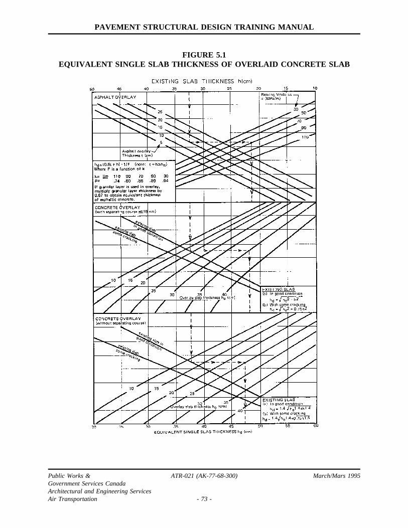
PAVEMENT STRUCTURAL DESIGN TRAINING MANUAL
FIGURE 5.1EQUIVALENT SINGLE SLAB THICKNESS OF OVERLAID CONCRETE SLAB
Public Works & ATR-021 (AK-77-68-300) March/Mars 1995Government Services CanadaArchitectural and Engineering ServicesAir Transportation - 73 -

PAVEMEN T STRUCTURAL DESIGN TRAININ G MANUAL
FIGURE 5.2CONSTRUCTION DETAIL S FOR OVERLAYIN G OPERATIONA L RUNWAYS
Public Works & ATR-021 (AK-77-68-300) March/Mars 1995Government Services CanadaArchitectural and Engineering ServicesAir Transportation - 74 -

PAVEMENT STRUCTURAL DESIGN TRAINING MANUAL
6.0 PLANNING AND PROGRAMMING
6.1 PROJECT JUSTIFICATION AND SCHEDULING
Capital work pavement projects fall into two broad categories. The first category consistsof new pavement construction projects, which represent an expansion of the presentsystem. The second category consists of pavement restoration projects, where the workis needed to maintain the existing system in an operational condition, and no increase inpavement inventory results.
The justification for new pavement facilities is established through master planningactivities. The National Airports Plan and Area Master Plans identify the need for newairport sites. The Airport Master Plan provides justification for the expansion of facilitiesat an existing airport. In general, justification is based on a capacity analysis of existingfacilities, and the construction of new facilities is scheduled when traffic projectionsindicate that demand will exceed capacity.
The need for pavement restoration is established through pavement evaluation activitieswhich monitor such pavement characteristics as structural condition, bearing strength,roughness and skid resistance. The main evaluation activity used for the justification andscheduling of restoration is pavement condition surveys performed in accordance withAK-68-32 "Pavement Evaluation: Condition Surveys". When a pavement is newlyconstructed, the restoration year is estimated by adding the average service life for thetype of construction involved to the year of construction. As the pavement matures andthe rate of deterioration is established through periodic condition surveys, restorationscheduling is modified to the year in which it is estimated that normal maintenance willnot be sufficient to keep the pavement operational.
In project justification and scheduling for new pavement facilities, the master planproviding justification for the project should be referenced and be available for study, andinclude a demand/capacity and a cost/benefit analysis. The latest condition survey reportshould be attached to project justification.
Public Works & ATR-021 (AK-77-68-300) March/Mars 1995Government Services CanadaArchitectural and Engineering ServicesAir Transportation - 75 -
PAVEMENT STRUCTURAL DESIGN TRAINING MANUAL
6.2 DESIGN ALTERNATIVES AND SELECTION
In most design situations, alternatives exist with respect to the type of pavement to beprovided and design details. It is not the designers function to choose between thesealternatives, although a recommendation should be given. The major responsibility of thedesigner is to assist management in reaching a decision by outlining the alternativesavailable along with their costs and operational implications.
The following guidelines apply generally to alternatives and selection in pavement design:
(a) All types of pavement structure satisfying operational requirements should beconsidered. The operational requirements should come from, or at least beapproved by, the facility operator.
(b) Selection between design alternatives for new pavements should be based onminimum life cycle costs as discussed in Section 6.3. For restoration projects,disruption of traffic also becomes a factor in the selection between designalternatives.
(c) Aircraft pavements intended to provide year round uninterrupted service shouldgenerally be surfaced with asphaltic or Portland cement concrete, unless technicalor economic reasons exist for a lower quality pavement structure.
(d) New aircraft pavements subject to turning movements, such as aprons, holdingareas, and runway buttons, should be surfaced with Portland cement concrete ifthe traffic consists of heavy aircraft with tire pressures exceeding 1.0 MPa.
(e) Aprons surfaced with asphaltic concrete should be provided with a coal tar slurryseal in refuelling areas.
6.3 LIFE CYCLE COSTING
Cost analysis for the comparison of pavement design alternatives should be performed inaccordance with AK-76-06 "Life Cycle Costing Procedures". For a comparison of relativecosts, a present value is calculated for each design alternative according to Eq. (6.1).
(6.1)
Public Works & ATR-021 (AK-77-68-300) March/Mars 1995Government Services CanadaArchitectural and Engineering ServicesAir Transportation - 76 -

PAVEMENT STRUCTURAL DESIGN TRAINING MANUAL
6.3 LIFE CYCLE COSTING (CONT’D)
where Pv = present value of the facility ($)
n = analysis period (years)
C = initial construction cost ($)
Ri = restoration or maintenance cost in year i
Vn = residual value of the facility at the end of the analysis period
r = discount rate applied to future costs or values.
An analysis period of 25 to 30 years is normally used for pavement construction projects.With an analysis period of this duration, the residual value discounted to a present valueis small and can be assumed equal for all alternatives. Under these circumstances, residualvalue can be eliminated from equation (6.1) when Pv is being calculated only for relativecomparison purposes.
All costs in Eq. (6.1) are calculated in terms of present day dollar value. The applicationof a discount rate to these costs when they are expended in the future reflects theadvantages of delaying expenditures. These advantages include the average differencebetween interest and inflation rates, possible productivity gains in the future, and moreaccurate assessments of future requirements as time progresses.
The discount rate normally applied to future expenditures and values is 10 percent.Additional calculations at 5 and 15 percent may be made to determine the sensitivity ofthe decision process to this factor.
The present value of design alternatives bears little relationship to the actual costs of thefacility over its life cycle; present value is simply a relative measure for comparisonpurposes.
6.4 DESIGN BRIEF
A design brief is a concise statement of the design parameters for a project, the designoptions studied, their costs and operational consequences. An example is given in Table6.1.
Program approval documents need-only provide the project design parameters, summary
Public Works & ATR-021 (AK-77-68-300) March/Mars 1995Government Services CanadaArchitectural and Engineering ServicesAir Transportation - 77 -

PAVEMENT STRUCTURAL DESIGN TRAINING MANUAL
6.4 DESIGN BRIEF (CONT’D)
of design options, and costs for the recommended option. However, a design brief shouldbe available for examination in the event that the recommendation is challenged.
6.5 PAVEMENT SERVICE LIFE
The service life of a pavement is the time period in years between construction andrestoration of the pavement surface. This variable is important in the programming ofrestoration measures, and for the life cycle cost comparison of different design options.
Some distributions of service life experienced at Canadian airports are given in Figures6.1, 6.2 and 6.3 for various types of construction.
For planning purposes service lives corresponding to the 50 percentile value shouldgenerally be used; a value closer to the 75 percentile may be used for light trafficconditions. Values less than the 50 percentile should be used if the pavement is deficientwith respect to construction materials, frost protection or bearing strength. A recycled orreplaced asphalt surface may be assumed to have a service life equal to a new asphaltpavement.
Public Works & ATR-021 (AK-77-68-300) March/Mars 1995Government Services CanadaArchitectural and Engineering ServicesAir Transportation - 78 -

PAVEMENT STRUCTURAL DESIGN TRAINING MANUAL
TABLE 6.1 - DESIGN BRIEF SUMMARY (EXAMPLE)
Project:
Restoration of Runway
The following example of life cycle cost analysis applies to an airport where theriding quality of the runways has declined over the years due to increased surfaceroughness caused by frost action and the introduction of heavier aircraft.
Design Alternatives:
Alternative "A" Provision of a 75mm hot mix overlay for the center 12m of the existingsurface, tapering to approximately 38mm on the shoulders. Expected life10 years. Capital Cost $2,229,000.00.
Alternative "B" Replacement of the central slabs 12 m wide with 380mm PortlandCement Concrete, maintaining the original design. Expected life 25years. Capital Cost $4,877,000.00.
Alternatives will be compared over a 30 year period using a discount rate of 10%.
Maintenance costs are not known but it is assumed that they will differ very little betweenalternatives.
Calculation of present value:
Alternative A = $3,421,000Alternative B = $5,104,000
Sensitivity Analysis performed for discount rates of 5% and 10%
@5% Alternative A = $4,438,000 @15% A = $2,916,000Alternative B = $5,415,000 B = $4,964,000
Conclusions:
Alternative "A" is more economical under these circumstances.
Public Works & ATR-021 (AK-77-68-300) March/Mars 1995Government Services CanadaArchitectural and Engineering ServicesAir Transportation - 79 -

PAVEMENT STRUCTURAL DESIGN TRAINING MANUAL
FIGURE 6.1NEW ASPHALT PAVEMENTS - DISTRIBUTION OF SERVICE LIFE
Public Works & ATR-021 (AK-77-68-300) March/Mars 1995Government Services CanadaArchitectural and Engineering ServicesAir Transportation - 80 -

PAVEMENT STRUCTURAL DESIGN TRAINING MANUAL
FIGURE 6.2NEW P.C.C. PAVEMENTS - DISTRIBUTION OF SERVICE LIFE
Public Works & ATR-021 (AK-77-68-300) March/Mars 1995Government Services CanadaArchitectural and Engineering ServicesAir Transportation - 81 -

PAVEMENT STRUCTURAL DESIGN TRAINING MANUAL
FIGURE 6.3ASPHALT OVERLAYS - DISTRIBUTION OF SERVICE LIFE
Public Works & ATR-021 (AK-77-68-300) March/Mars 1995Government Services CanadaArchitectural and Engineering ServicesAir Transportation - 82 -
PAVEMENT STRUCTURAL DESIGN TRAINING MANUAL
7.0 MISCELLANEOUS DESIGN TOPICS
7.1 PAVEMENTS ON PERMAFROST
Subgrade soil conditions are a critical element for airfield site selection in permafrostareas. Fine-grained subgrade soils with high ice contents are to be avoided as they arevery unstable during thaw, and large settlements are likely to occur. The best subgradesoils for pavement construction in northern Canada are granular materials with low icecontent. The availability of construction materials may also be critical at some sites. Soiland material survey methods to be followed for permafrost areas are outlined in AK-77-68-600 "Geotechnical Surveys - Training Manual".
In northern permafrost areas where the active layer is not too deep, the normal approachto pavement design is to provide a pavement and embankment thickness such that thawdoes not reach the existing in-situ material. In southern permafrost areas where deeperactive layers render this approach uneconomical, pavement design is based on strengthconsiderations using a subgrade bearing strength estimated for the thawed subgrade soil.Pavement insulation may also be a feasible design alternative for permafrost areas.
When the active layer penetrates the subgrade soil, substantial movements can beexpected in the pavement structure after construction as the subsurface permafrost regimeadjusts to a new equilibrium state. It is preferable to have the surface unpaved, asirregularities can be corrected more easily and economically with gravel surfaces. Wherepaving is an operational necessity, a requirement for resurfacing courses can be expectedat five to ten-year intervals unless subgrade soil conditions are exceptionally favourable.
Drainage is also an important consideration for northern airfield pavements. Water actsas a heat sink and changes to the surface drainage pattern should be minimized as theywill frequently result in permafrost degradation and large settlements. Pavementsubsurface drainage is difficult as pipes located at depth will provide subsurface drainagefor only a short period of the year. A double layer of pipe may be considered i.e. anupper pipe for drainage during the early thaw period and a lower pipe for drainage towardthe end of the thaw period.
Public Works & ATR-021 (AK-77-68-300) March/Mars 1995Government Services CanadaArchitectural and Engineering ServicesAir Transportation - 83 -

PAVEMENT STRUCTURAL DESIGN TRAINING MANUAL
7.2 PROOF ROLLING
During the construction of a pavement, proof rolling is conducted at some level in thesub-base or base course for the purpose of checking the uniformity of subgrade bearingstrength. Isolated weak areas identified by proof rolling are corrected to increase thesignificant strength and uniformity of the total area. As a side benefit, proof rollingprovides additional compaction for the pavement structure.
The standard vehicle used for proof rolling is a rubber-tired roller having four wheelsabreast with a maximum centre-to-centre wheel spacing of 92 cm, tire inflation pressureof 0.62 MPa, and a total weight of 445 kN. The level for proof rolling chosen by thedesigner should create a subgrade overload ratio of two using the standard proof rollingequipment. Figure 7.1 shows the required pavement depth as a function of subgradebearing strength.
In the case of strong subgrades where the roller cannot provide an overload ratio of two,proof rolling is carried out on the first lift of sub-base. In the case of weak subgrades andthinner pavements where the standard roller gives an overload ratio greater than two,proof rolling is carried out on the surface of the base course at a reduced roller weightwhich gives an overload ratio of two. Where proof rolling is on a sub-base materialunstable under a tire pressure of 0.62 MPa, tire pressures should be reduced.
Contractors may request to use alternative proof rolling equipment. The designer shouldprepare a design-evaluation chart for the alternative proof rolling equipment to determinethe level at which proof rolling should be carried out.
Public Works & ATR-021 (AK-77-68-300) March/Mars 1995Government Services CanadaArchitectural and Engineering ServicesAir Transportation - 84 -

PAVEMENT STRUCTURAL DESIGN TRAINING MANUAL
FIGURE 7.1 - LEVEL OF PROOF ROLLING
Public Works & ATR-021 (AK-77-68-300) March/Mars 1995Government Services CanadaArchitectural and Engineering ServicesAir Transportation - 85 -

PAVEMENT STRUCTURAL DESIGN TRAINING MANUAL
BIBLIOGRAPHY
1. Argue, G.H. and B.B. Denyes. Estimating the Depth of Pavement Frost and ThawPenetrations. Transportation Research Record 497 (Soil Properties), National ResearchCouncil, Washington, D.C., 1974, pages 18-30.
2. Asphalt Institute. Asphalt Overlays and Pavement Rehabilitation. Manual Series No. 17(MS-17), First Edition, The Asphalt Institute, November 1969.
3. Asphalt Institute. Full-Depth Asphalt Pavements for Air Carrier Airports. Manual SeriesNo. 11 (MS-11), The Asphalt Institute, January 1973.
4. Asphalt Institute. Thickness Design - Full-Depth Asphalt Pavement Structures forHighways and Streets. Manual Series No. 1 (MS-1), Revised Eighth Edition, The AsphaltInstitute, August 1970.
5. Berg, Richard L. Design of Civil Airfield Pavements for Seasonal Frost and PermafrostConditions. AD/A - 006284, National Technical Information Service, U.S. Department ofCommerce, Springfield, Va., October 1974.
6. Department of Transport. Engineering Planning, Design and Construction Manual Section1 - Design and Evaluation of Flexible and Rigid Pavements. Department of Transport, AirServices, Construction Engineering and Architectural Branch, Ottawa, July 1969.
7. Department of the Air Force. Pavement Design for Frost Conditions. AFM-88-6, Chap.4, U.S. Department of the Air Force, Washington, D.C., May 1962.
8. Department of the Army. Arctic and Subarctic Construction - Runway and Road Design.TM5-852-3, U.S. Department of the Army, Washington, D.C., October 1954.
9. Department of the Navy. Design Manual - Airfield Pavements. NAVFAC DM-21,Alexandria, Virginia, 1973.
10. Departments of the Army and the Air Force. Airfield Flexible Pavements - Air Force.TM5-824-2 (AFM 88-6, Chap. 2) Departments of the Army and the Air Force,Washington, D.C., February 1969.
11. Department of the Army and the Air Force. Pavement Design for Frost Conditions -Emergency Construction. TM5-887-6/AFM 88-40, Chap. 32, U.S. Departments of theArmy and the Air Force, Washington, D.C., July 1966.
Public Works & ATR-021 (AK-77-68-300) March/Mars 1995Government Services CanadaArchitectural and Engineering ServicesAir Transportation - 86 -

PAVEMENT STRUCTURAL DESIGN TRAINING MANUAL
BIBLIOGRAPHY (CONT’D)
12. Departments of the Army and the Air Forces. Rigid Pavements for Airfields Other thanArmy. TM5-824-3 (AFM 88-6, Chap. 3), U.S. Department of the Army and the AirForce, Washington, D.C., December 1970.
13. Federal Aviation Agency. Airport Pavement Design and Evaluation. Advisory Circular,AC 150/5320-68, U.S. Department of Transportation, Washington, D.C., May 1974.
14. Highway Research Board. Pavement Design in Frost Areas, II, Design Considerations.Highway Research Record Number 33, National Research Council, Washington, D.C.,1963.
15. International Business Machines Corporation (IBM). CALL/360:**PDILB - AirportConcrete Paving Design. GE 19-0055-0, First Edition, IBM, New York, 1970.
16. International Civil Aviation Organization (ICAO). Aerodrome Physical Characteristics -Part 2. DOC7920-AN/865/2, Aerodrome Manual, Second Edition, ICAO, Montreal, 1965.
17. McLeod, Norman W. Airport Runway Evaluation in Canada. Department of Transport,Ottawa, August 1947.
18. Packard, Robert G. Computer Program for Airport Pavement Design. Portland CementAssociation, Skokie, Illinois, 1967.
19. Packard, Robert G. Design of Concrete Airport Pavement. Portland Cement Association,Skokie, Illinois, 1973.
20. Pickett, Gerald and Gordon K. Ray. Influence Charts for Concrete Pavements. AmericanSociety of Civil Engineer Transactions, Paper No. 2425, Vol. 116,1951, pages 49 to 73.
21. Pickett, Gerald, Milton E. Raville, William C. Jones, Frank J. McCormick. Deflections,Moments, and Reactive Pressures for Concrete Pavements. Kansas State College, BulletinNo. 65,1951.
22. Portland Cement Association. Design of Concrete Pavements for City Streets. PortlandCement Association, Skokie, Illinois 1974.
23. Portland Cement Association. Joint Design for Concrete Highway and Street Pavements.Portland Cement Association, Skokie, Illinois, 1975.
Public Works & ATR-021 (AK-77-68-300) March/Mars 1995Government Services CanadaArchitectural and Engineering ServicesAir Transportation - 87 -

PAVEMENT STRUCTURAL DESIGN TRAINING MANUAL
BIBLIOGRAPHY (CONT’D)
24. Portland Cement Association. Load Stresses at Pavement Edge. Portland CementAssociation, Skokie, Illinois, 1969.
25. Portland Cement Association. PCA Soil Primer. Portland Cement Association, Skokie,Illinois, 1973.
26. Portland Cement Association. Subgrades and Subbases for Concrete Pavements. PortlandCement Association, Skokie, Illinois, 1971.
27. Portland Cement Association. Thickness Design for Concrete Pavements. Portland CementAssociation, Skokie, Illinois, 1966.
28. Roads and Transportation Association of Canada - Pavement Management Guide. Roadand Transportation Association of Canada, Ottawa.
29. Sargious, Michel. Pavements and Surfacing for Highway and Airports. John Wiley andSons, Inc., New York, 1975.
30. Westergaard, H.M. New Formula for Stresses in Concrete Pavements of Airfields.American Society of Civil Engineers Transactions, vol. 113, 1948.
31. Westergaard, H.M. Theory of Concrete Pavement Design. Proceedings, Highway ResearchBoard, 1972.
32. Yoder, E.J. and M.W. Witczak. Principles of Pavement Design. 2nd edition, John Wileyand Sons, Inc., Toronto, 1975.
Public Works & ATR-021 (AK-77-68-300) March/Mars 1995Government Services CanadaArchitectural and Engineering ServicesAir Transportation - 88 -

PAVEMENT STRUCTURAL DESIGN TRAINING MANUAL
APPENDIX A
AIRCRAFT LOADING CHARACTERISTICS
Public Works &Government Services Canada ATR-021 (AK-77-68-300) March/Mars 1995Architectural and Engineering ServicesAir Transportation - A1 -

PAVEMENT STRUCTURAL DESIGN TRAINING MANUAL
AIRCRAFT LOADING CHARACTERISTICS
Aircraft Op. Weight (kN) % Load Tire Wheel Spacing(cm)
On Gear PressMax. Min. (MPa) Dual Tandem
AERO COMMANDER GRAND,TURBO 40 25 47.5 0.55 -- --
AERO COMMANDER, JETCOMMANDER 75 55 47.5 0.93 -- --
AIRBUS A300-B2, B4 1540 900 47.3 1.30 91 140
AIRBUS A300-C4 1627 1216 47.3 1.24 95 146
AIRBUS 310-200 1303 1064 46.6 1.12 95 140
ANTONOV AN-24 207 130 47.5 0.42 58 --
ARGOSY AW650 410 250 47.5 O.55 71 --
B707-120B 1150 700 47.0 1.17 86 142
B707-320, 320B, 320C, 420 1500 800 47.0 1.24 88 142
B720, 720B 1045 700 47.5 1.00 81 124
B727-100, 100C 760 400 45.4 1.25 86 --
B727-200 (St/Ad) 935 500 47.0 1.25 86 --
B737-100, 200 450 250 46.5 1.00 78 --
B737-200, 200C 575 300 46.5 1.20 78 --
B737-300 603 323 45.9 1.34 78 --
B747-1OOB, SR 2330 1600 24.0 1.04 112 147
B747-SP 3130 1500 23.0 1.35 110 137
B747-100, 100B, SR 3350 1700 23.5 1.55 112 147
Public Works &Government Services Canada ATR-021 (AK-77-68-300) March/Mars 1995Architectural and Engineering ServicesAir Transportation - A2 -

PAVEMENT STRUCTURAL DESIGN TRAINING MANUAL
AIRCRAFT LOADING CHARACTERISTICS
Aircraft Op. Weight (kN) % Load Tire Wheel Spacing(cm)
On Gear PressMax. Min. (MPa) Dual Tandem
B747-200B, 200C, 200F 3720 1700 24.0 1.35 112 147
B747-300 3720 1715 22.7 1.30 -- --
B757-200 1075 560 45.2 1.17 86 114
B767-200 1410 783 46.3 1.31 114 142
B767-200 ER, 300 1566 800 46.3 1.21 114 142
BAC-111-Srs 400, 500 465 250 45.0 1.05 53 --
BAE-146-100 366 225 46.0 0.80 71 --
BAE-146-100 366 225 46.0 0.52 71 --
BAE-146-200 398 225 47.1 0.88 71 --
BAE-146-200 398 225 47.1 0.61 71 --
BANDEIRANTE 58 35 47.5 0.62 -- --
BEECH BONANZA 35, 36 17 10 47.5 0.28 -- --
BEECH BARON 55, 58 28 15 47.5 0.38 -- --
BEECH KING AIR 90 Srs 49 26 47.5 0.38 -- --
BEECH KING AIR B100,SUPER 200 56 32 47.5 0.73 29 --
BEECH QUEEN AIR 65, 7080 Srs, 88 40 24 47.5 0.33 -- --
BRITTANIA 300 825 400 47.5 1.00 F51 122R76
C5A GALAXY (Lockheed) 3400 1500 23.5 0.77 86 F165R165
Public Works &Government Services Canada ATR-021 (AK-77-68-300) March/Mars 1995Architectural and Engineering ServicesAir Transportation - A3 -
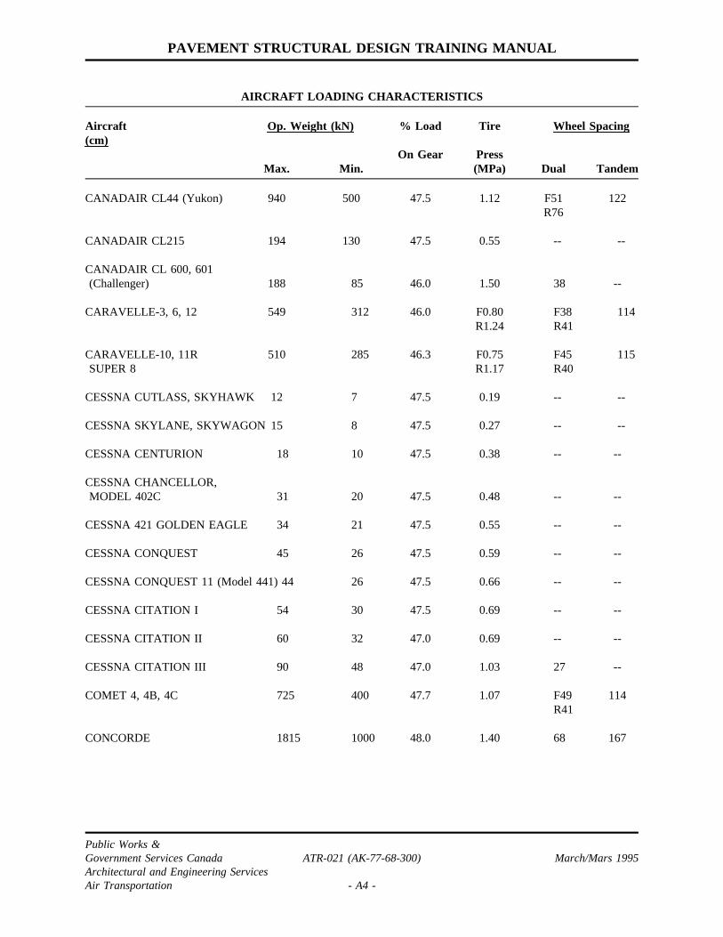
PAVEMENT STRUCTURAL DESIGN TRAINING MANUAL
AIRCRAFT LOADING CHARACTERISTICS
Aircraft Op. Weight (kN) % Load Tire Wheel Spacing(cm)
On Gear PressMax. Min. (MPa) Dual Tandem
CANADAIR CL44 (Yukon) 940 500 47.5 1.12 F51 122R76
CANADAIR CL215 194 130 47.5 0.55 -- --
CANADAIR CL 600, 601(Challenger) 188 85 46.0 1.50 38 --
CARAVELLE-3, 6, 12 549 312 46.0 F0.80 F38 114R1.24 R41
CARAVELLE-10, 11R 510 285 46.3 F0.75 F45 115SUPER 8 R1.17 R40
CESSNA CUTLASS, SKYHAWK 12 7 47.5 0.19 -- --
CESSNA SKYLANE, SKYWAGON 15 8 47.5 0.27 -- --
CESSNA CENTURION 18 10 47.5 0.38 -- --
CESSNA CHANCELLOR,MODEL 402C 31 20 47.5 0.48 -- --
CESSNA 421 GOLDEN EAGLE 34 21 47.5 0.55 -- --
CESSNA CONQUEST 45 26 47.5 0.59 -- --
CESSNA CONQUEST 11 (Model 441) 44 26 47.5 0.66 -- --
CESSNA CITATION I 54 30 47.5 0.69 -- --
CESSNA CITATION II 60 32 47.0 0.69 -- --
CESSNA CITATION III 90 48 47.0 1.03 27 --
COMET 4, 4B, 4C 725 400 47.7 1.07 F49 114R41
CONCORDE 1815 1000 48.0 1.40 68 167
Public Works &Government Services Canada ATR-021 (AK-77-68-300) March/Mars 1995Architectural and Engineering ServicesAir Transportation - A4 -

PAVEMENT STRUCTURAL DESIGN TRAINING MANUAL
AIRCRAFT LOADING CHARACTERISTICS
Aircraft Op. Weight (kN) % Load Tire Wheel Spacing(cm)
On Gear PressMax. Min. (MPa) Dual Tandem
CONVAIR 240 190 125 46.0 0.64 55 --
CONVAIR 340, 440, 540 220 140 47.0 0.47 62 --
CONVAIR 580 260 140 47.0 0.50 62 --
CONVAIR 600 210 140 45.8 0.73 54 --
CONVAIR 640 285 180 45.8 0.52 61 --
CONVAIR 880 860 400 46.6 1.03 55 114
CONVAIR 990 1135 600 48.5 1.28 61 118
DART HERALD 200 120 45.0 0.43 48 --
DASSAULT FALCON 10 84 50 47.5 0.93 24 --
DASSAULT FALCON 20 128 75 47.5 0.92 24 --
DASSAULT FALCON 50 173 90 47.5 0.93 38 --
DC-3 147 80 46.8 0.31 -- --
DC-4 335 200 46.8 0.53 74 --
DC-6, 6B 480 300 44.0 0.73 78 --
DC-7 (All Models) 640 400 47.5 0.89 78 --
DC-8-10, 20 Srs 1240 600 47.5 1.01 76 140
DC-8-43, 55, 61, 71 1470 800 47.5 1.26 76 140
DC-8-61F, 62F, 63F 1557 1001 47.5 1.35 76 140
DC-8-62, 63, 72, 73 1600 800 48.0 1.35 81 140
DC-9-15 407 300 46.2 0.90 61 --
Public Works &Government Services Canada ATR-021 (AK-77-68-300) March/Mars 1995Architectural and Engineering ServicesAir Transportation - A5 -

PAVEMENT STRUCTURAL DESIGN TRAINING MANUAL
AIRCRAFT LOADING CHARACTERISTICS
Aircraft Op. Weight (kN) % Load Tire Wheel Spacing(cm)
On Gear PressMax. Min. (MPa) Dual Tandem
DC-9-21, 32 485 300 47.2 1.10 64 --
DC-9-41, 51 545 300 47.0 1.15 66 --
DC-10-10 1971 1032 46.9 1.31 137 163
DC-10-15 2037 1032 46.7 1.34 137 163
DC-10-20, 20CF, 30CF 2482 1637 34.9 1.14 137 163
DC-10-30, 40 2638 1217 37.9 1.24 137 163
DH104 DOVE, DEVON 42 30 45.0 0.32 -- --
DHC1 CHIPMUNK 10 7 47.5 0.21 -- --
DHC2 BEAVER 25 14 47.5 0.17 -- --
DHC3 OTTER 36 20 47.5 0.20 -- --
DHC4 CARIBOU 130 90 43.0 0.28 51 --
DHC5 BUFFALO 187 115 47.5 0.41 51 --
DHC6 TWIN OTTER 56 35 45.5 0.26 -- --
DHC7 DASH 7 197 120 46.8 0.74 42 --
DHC8 DASH 8 136 90 47.5 0.44 49 --
F27 FRIENDSHIP 200 125 47.5 0.54 45 --
F28 FELLOWSHIP 325 175 47.0 0.76 55 --
FAIRCHILD FH227 205 105 47.5 0.73 48 --
GATES LEARJET 25D,LONGHORN 29 69 34 47.5 0.79 25 --
Public Works &Government Services Canada ATR-021 (AK-77-68-300) March/Mars 1995Architectural and Engineering ServicesAir Transportation - A6 -

PAVEMENT STRUCTURAL DESIGN TRAINING MANUAL
AIRCRAFT LOADING CHARACTERISTICS
Aircraft Op. Weight (kN) % Load Tire Wheel Spacing(cm)
On Gear PressMax. Min. (MPa) Dual Tandem
GATES LEARJET 35A, 36A 82 42 47.5 0.79 28 --
GATES LEARJET 55, 56 93 49 47.5 0.80 32 --
GULFSTREAM COMMANDER 50 30 47.5 0.48 -- --
GULFSTREAM G159 156 100 47.5 0.83 42 --
GULFSTREAM II 294 150 47.5 1.03 46 --
GULFSTREAM III 306 150 47.5 1.21 46 --
HERCULES C130, L100-20-30, 695 400 47.5 0.74 -- 154L382
HS 125-700 (BAe) (DOMINIE) 112 60 45.5 0.83 32 --
HS 748-2B (BAe) 210 120 43.6 0.59 48 --
HS TRIDENT 3B, SUPER 3B, 707 400 47.0 1.17 2D @ 30 --TRIDENT 3, SUPER 3, Pairs @ 95TRIDENT 2E
ILYUSHIN IL-18 625 350 47.5 0.80 77 105
ILYUSHIN IL-62, 62M 1648 651 47.0 1.08 80 165
ILYUSHIN IL-76T 1677 822 47.0 0.64 2DT Pairs --(62 x 258)
@ 144
ILYUSHIN IL-86 2054 1089 31.2 0.88 125 149
JETSTAR L329, C140 (Lockheed) 190 100 42.5 1.52 34
L1011-1 TRISTAR,-385-1 1925 1400 47.5 1.33 132 178
L1011-100, 200, 500 TRISTAR 2215 1400 46.8 1.25 132 178
Public Works &Government Services Canada ATR-021 (AK-77-68-300) March/Mars 1995Architectural and Engineering ServicesAir Transportation - A7 -

PAVEMENT STRUCTURAL DESIGN TRAINING MANUAL
AIRCRAFT LOADING CHARACTERISTICS
Aircraft Op. Weight (kN) % Load Tire Wheel Spacing(cm)
On Gear PressMax. Min. (MPa) Dual Tandem
L1049 SUPER CONSTELLATION 625 300 48.2 0.85 71 --
L188 ELECTRA 515 350 47.5 1.00 66 --
L649 418 250 47.5 0.55 71 --
L749/749A 476 300 47.5 O.59 71 --
MD-81,87 627 325 47.9 1.17 -- --
MD-82 669 349 47.6 1.27 -- --
MD-83 716 355 47.4 1.34 -- --
MERCURE-DASSAULT 559 471 47.5 0.97 65 --
MITSUBISHI MU-2 52 34 47.5 0.44 -- --
MITSUBISHI DIAMOND 1A 72 40 47.5 0.83 -- --
PIPER CUB 8 5 47.5 0.13 -- --
PIPER SEMINOLE 18 11 47.5 0.25 -- --
PIPER APACHE, COMMANCHE,SENECA 21 13 47.5 0.29 -- --
PIPER AZTEC/NAVAJO 30 18 47.5 0.42 -- --
PIPER CHEYENNE I/II 43 22 47.5 0.55 -- --
PIPER CHEYENNE III 50 28 47.5 0.69 -- --
SAUNDERS ST27 60 35 47.5 0.43 -- --
SHORTS SKYVAN SC7 56 35 41.0 0.28 -- --
SHORTS 330 102 66 47.5 0.55 -- --
Public Works &Government Services Canada ATR-021 (AK-77-68-300) March/Mars 1995Architectural and Engineering ServicesAir Transportation - A8 -

PAVEMENT STRUCTURAL DESIGN TRAINING MANUAL
AIRCRAFT LOADING CHARACTERISTICS
Aircraft Op. Weight (kN) % Load Tire Wheel Spacing(cm)
On Gear PressMax. Min. (MPa) Dual Tandem
SHORTS 360 256 155 47.5 0.76 -- --
STARLIFTER LOCKHEED C141 1415 600 46.7 1.25 82 122
SWEARINGEN METRO II, IIA andMERLIN IIIB, IIIC, IVA 59 36 47.5 0.69 29 --
SWEARINGEN METRO III andMERLIN IVC 65 36 47.5 0.69 29 --
TUPOLEV TU104 765 400 45.0 0.98 F 95 120R 100
TUPOLEV TU 134A 467 288 45.6 0.83 56 99
TUPOLEV TU 154, 154B 961 525 45.1 0.93 62 F103R98
VANGUARD 950 Srs 655 400 47.5 0.83 74 --
VC10-1100 Srs 1395 700 47.8 0.84 86 155
VC10-1150 SUPER 1490 800 48.2 1.01 86 155
VISCOUNT 700, 800 335 200 46.0 0.88 48 --
YS11(NIHON) 245 160 47.5 0.52 52 --
Revised: May 30,1986
Public Works &Government Services Canada ATR-021 (AK-77-68-300) March/Mars 1995Architectural and Engineering ServicesAir Transportation - A9 -

PAVEMENT STRUCTURAL DESIGN TRAINING MANUAL
APPENDIX B
DEVELOPMENT OF FLEXIBLE PAVEMENT
DESIGN EQUATION
Public Works &Government Services Canada ATR-021 (AK-77-68-300) March/Mars 1995Architectural and Engineering ServicesAir Transportation - B1 -

PAVEMENT STRUCTURAL DESIGN TRAINING MANUAL
FLEXIBLE LOAD PROPORTIONALITY
Plate Load Proportionality
Based on the many tests conducted at Canadian airports during the initial years of plate loadtesting, it was observed that for a given thickness of base course placed over subgrade, the platebearing value at the surface of the base tended to be directly proportional to the bearing valueat the surface of the subgrade. In mathematical terms:
OR
where P = plate bearing value at the surface of the base course
(B-1)
S = plate bearing value at the surface of the subgradeC = constant of proportionality between P and S
This statement of proportionality is valid only when P and S are measured with the same sizeof bearing plate and at the same deflection and number of load repetitions.
Development of McLeod Equation
The McLeod equation relating plate bearing values at the surface of base course and subgradeis developed by dividing the base course into layers of unit thickness and applying theassumption of proportionality outlined above.
In Figure B-1, the base course t units in thickness is divided into levels 1, 2, 3, ..., t with thethickness between each level being 1 unit. P1 designates the plate bearing value measured on thesurface of the ith level. Applying the assumption of proportionality given in eq. B-1,
OR
Considering the surface of level 1 to be a "new" subgrade surface:
Public Works &Government Services Canada ATR-021 (AK-77-68-300) March/Mars 1995Architectural and Engineering ServicesAir Transportation - B2 -

PAVEMENT STRUCTURAL DESIGN TRAINING MANUAL
Considering the surface of level 2 to be a "new" subgrade surface:
Continuing in this manner until the surface of the base course is reached,
or
The value 1/[log (P1/S)] is designated as K and is assumed to be independent of the type of basecourse material. McLeod’s equation is thus stated as:
or
(B-2)
(B-3)
McLeods Constant K
The constant K in Eq. B-2 is a measure of the increase in bearing strength per unit thickness ofbase course. For Eq. B-2 to be balanced dimensionally, K has to have the same dimensions ast.
Public Works &Government Services Canada ATR-021 (AK-77-68-300) March/Mars 1995Architectural and Engineering ServicesAir Transportation - B3 -

PAVEMENT STRUCTURAL DESIGN TRAINING MANUAL
From various geotechnical and foundation design theories, the value of the constant K has to bedependent on the size of the bearing plate used in measurement. The function of K versus sizeof bearing plate given in Figure 3.3 was determined from field plate bearing tests using differentsizes of bearing plates.
Comparison with Layered Elastic Theory
Elastic theory applied to a two layer system representing a base course over subgrade suggeststhat the load ratio P/S is a function of the thickness ratio t/a and the modulus ratio E1/E2, wheret is the thickness of base course, a is the radius of the bearing plate and E1 and E2 are the elasticmoduli of the base course and subgrade respectively. The functional relationship between thesevariables as derived from elastic theory is shown in Figure B-2. Superimposed on Figure B-2 isthe McLeod relationship of load ratio P/S as a function of thickness ratio t/a.
The elastic model has some deficiencies when applied to plate load testing because pavementdeflection contains a plastic as well as elastic component, and modulus or stiffness values ofpavement materials vary with stress and strain levels. However, the comparison in Figure B-2serves to illustrate some limitations of the McLeod model. The equation P = S x 10t/K suggeststhat the base surface load P will continue to increase exponentially with increasing base thicknesst, but actually at high values, P will asymptotically approach a limiting value equal to the bearingvalue measured on an infinite depth of base course material. Similarly, the McLeod equationindicates that base course placed on subgrade will provide an increase in bearing strengthregardless of the value of the subgrade bearing strength. This effect does not occur if thesubgrade has a very high bearing value; in the extreme, one only has to consider the case ofplacing base material over rock subgrade. Despite these limitations, the McLeod model issufficiently accurate for most pavement conditions encountered and its usefulness has beendemonstrated over many years of experience.
As illustrated in Figure B-2, McLeod’s model corresponds to the layered elastic model for amodular ratio of about 5, for usual thicknesses of pavement structures.
The Design/Evaluation Equation
Equation B-3 is adapted to a design equation by substituting the equivalent single wheel load(ESWL) of the design vehicle for the surface plate bearing value P. The resulting equation maybe written as:
(B-4)
where S is the subgrade bearing strength required to support the ESWL for a pavement thickness
Public Works &Government Services Canada ATR-021 (AK-77-68-300) March/Mars 1995Architectural and Engineering ServicesAir Transportation - B4 -

PAVEMENT STRUCTURAL DESIGN TRAINING MANUAL
t. With the equation in this form, the subgrade bearing strength variable, S, and the variable, K,correspond to a contact area equal to that of the ESWL.
From the plate load interrelationships given in Figure 3.1, it can be shown that two plate loadsP1 and P2, giving a deflection of 12.5 mm when applied through plates of contact area A1 andA2 respectively, are related by:
(B-5)
If P1 is taken as the standard measure of subgrade bearing strength, Ss, obtained with a 75 cmdiameter plate (A1 = 4418 cm2), and P2 is a subgrade bearing strength S measured on a variablecontact area, A, then
(B-6)
Substituting Eq. B-6 into Eq. B-4:
(B-7)
where F = 7.3 x 10³
A(0.41 + 81.9/√A)
Ss = standard measure of subgrade bearing strength (kN, 750 mm diam plate,12.5 mm defl’n, 10 rep. of loading)
ESWL = design vehicle equivalent single wheel load (kN) determined as given inSection 3.2.5
A = contact area of the ESWL (cm2)
Public Works &Government Services Canada ATR-021 (AK-77-68-300) March/Mars 1995Architectural and Engineering ServicesAir Transportation - B5 -

PAVEMENT STRUCTURAL DESIGN TRAINING MANUAL
t = pavement thickness (cm)
K = variable depending on the contact area of the ESWL, as given inFigure 3.3
For evaluation purposes, Eq. B-7 is further modified by the addition of an overload ratio, R, toproduce the design/evaluation equation given in Section 3.2.6.
Public Works &Government Services Canada ATR-021 (AK-77-68-300) March/Mars 1995Architectural and Engineering ServicesAir Transportation - B6 -

PAVEMENT STRUCTURAL DESIGN TRAINING MANUAL
FIGURE B-1 - DEVELOPMENT OF McLEOD EQUATION
Public Works &Government Services Canada ATR-021 (AK-77-68-300) March/Mars 1995Architectural and Engineering ServicesAir Transportation - B7 -

PAVEMENT STRUCTURAL DESIGN TRAINING MANUAL
FIGURE B-2COMPARISON OF TWO LAYERED ELASTIC AND McLEOD’S MODELS
Public Works &Government Services Canada ATR-021 (AK-77-68-300) March/Mars 1995Architectural and Engineering ServicesAir Transportation - B8 -

PAVEMENT STRUCTURAL DESIGN TRAINING MANUAL
APPENDIX C
WESTERGAARD STRESS ANALYSIS
FOR INTERIOR LOADING OF CONCRETE SLAB
Public Works &Government Services Canada ATR-021 (AK-77-68-300) March/Mars 1995Architectural and Engineering ServicesAir Transportation - C1 -

PAVEMENT STRUCTURAL DESIGN TRAINING MANUAL
1.0 REFERENCES
(1) Pickett, Gerald, Milton E. Raville, William C. James, Frank J. McCormick.Deflections, Moments and Reactive Pressures for Concrete Pavements. KansasState College, Bulletin No. 65, 1951.
(2) Computer Program "RIGID" for Design and Evaluation of Airport RigidPavements.
2.0 WESTERGAARD ANALYSIS
In the analysis, the following assumptions are made regarding the concrete slab:
(1) the slab consists of homogeneous, isotropic, and elastic material;
(2) the slab is of uniform thickness;
(3) the loads on the top and on the bottom of the slab occur in a direction normal tothese surfaces;
(4) the range of relative thicknesses is such that the theory of thin plates may beapplied.
Based on these assumptions, the slab deflection must satisfy the following differentialequation:
(C-1)
whereσ2 = Laplace Differential Operator= δ2/δr2 + 1/r δ/δr + 1/r2 δ2/δΘ2 + δ2/δz2
D = Flexural Rigidity = Eh5/[12(1-µ2)]
E = Young’s modulus for slab (27,580 MPa assumed)
µ = Poisson’s ratio for slab (0.15 assumed)
h = thickness of slab
Public Works &Government Services Canada ATR-021 (AK-77-68-300) March/Mars 1995Architectural and Engineering ServicesAir Transportation - C2 -
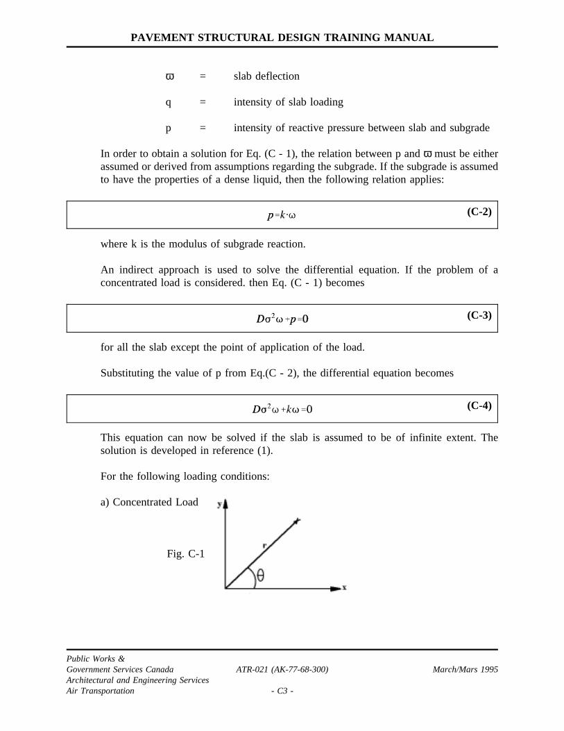
PAVEMENT STRUCTURAL DESIGN TRAINING MANUAL
ω = slab deflection
q = intensity of slab loading
p = intensity of reactive pressure between slab and subgrade
In order to obtain a solution for Eq. (C - 1), the relation between p andω must be eitherassumed or derived from assumptions regarding the subgrade. If the subgrade is assumedto have the properties of a dense liquid, then the following relation applies:
where k is the modulus of subgrade reaction.
(C-2)
An indirect approach is used to solve the differential equation. If the problem of aconcentrated load is considered. then Eq. (C - 1) becomes
for all the slab except the point of application of the load.
(C-3)
Substituting the value of p from Eq.(C - 2), the differential equation becomes
This equation can now be solved if the slab is assumed to be of infinite extent. The
(C-4)
solution is developed in reference (1).
For the following loading conditions:
a) Concentrated Load
Fig. C-1
Public Works &Government Services Canada ATR-021 (AK-77-68-300) March/Mars 1995Architectural and Engineering ServicesAir Transportation - C3 -
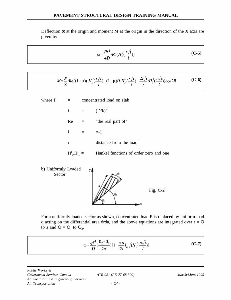
PAVEMENT STRUCTURAL DESIGN TRAINING MANUAL
Deflectionω at the origin and moment M at the origin in the direction of the X axis aregiven by:
(C-5)
(C-6)
where P = concentrated load on slab
l = (D/k)¼
Re = "the real part of"
i = √-1
r = distance from the load
HIs,H
I1 = Hankel functions of order zero and one
b) Uniformly LoadedSector
Fig. C-2
For a uniformly loaded sector as shown, concentrated load P is replaced by uniform loadq acting on the differential area drda, and the above equations are integrated over r =Θto a andΘ = Θ1 to Θ2.
(C-7)
Public Works &Government Services Canada ATR-021 (AK-77-68-300) March/Mars 1995Architectural and Engineering ServicesAir Transportation - C4 -

PAVEMENT STRUCTURAL DESIGN TRAINING MANUAL
where Im = "the imaginary part of"
(C-8)
The tensile stress at the bottom of the slab associated with this moment is given by:
(C-9)
For purposes of computer program development, Eq. (C - 8) is stated in the form:
(C-10)
Public Works &Government Services Canada ATR-021 (AK-77-68-300) March/Mars 1995Architectural and Engineering ServicesAir Transportation - C5 -

PAVEMENT STRUCTURAL DESIGN TRAINING MANUAL
3.0 LOADING CONDITIONS
The load is applied to the concrete slab through the aircraft tires. The shape of the tireimprint is assumed to be an ellipse as shown below.
Fig. C-3
The general equation for an ellipse is given by:
(C-11)
where A = half of the major axisB = half of the minor axis
It is assumed that length of the tire imprint is related to imprint area by (see Figure 3.6
Public Works &Government Services Canada ATR-021 (AK-77-68-300) March/Mars 1995Architectural and Engineering ServicesAir Transportation - C6 -
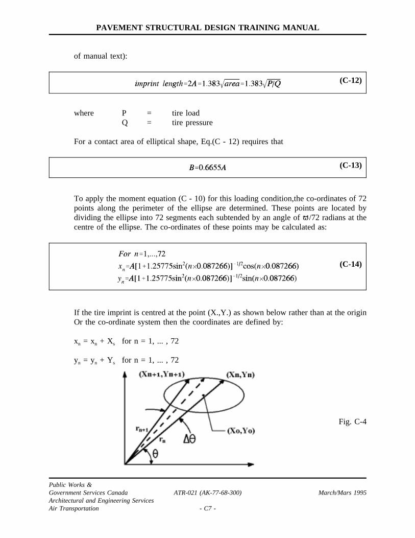
PAVEMENT STRUCTURAL DESIGN TRAINING MANUAL
of manual text):
(C-12)
where P = tire loadQ = tire pressure
For a contact area of elliptical shape, Eq.(C - 12) requires that
(C-13)
To apply the moment equation (C - 10) for this loading condition,the co-ordinates of 72points along the perimeter of the ellipse are determined. These points are located bydividing the ellipse into 72 segments each subtended by an angle of /72 radians at thecentre of the ellipse. The co-ordinates of these points may be calculated as:
(C-14)
If the tire imprint is centred at the point (X.,Y.) as shown below rather than at the originOr the co-ordinate system then the coordinates are defined by:
xn = xn + Xs for n = 1, ... , 72
yn = yn + Ys for n = 1, ... , 72
Fig. C-4
Public Works &Government Services Canada ATR-021 (AK-77-68-300) March/Mars 1995Architectural and Engineering ServicesAir Transportation - C7 -

PAVEMENT STRUCTURAL DESIGN TRAINING MANUAL
4.0 MOMENT DUE TO GEAR LOADING
To calculate the moment at the origin in the direction of the X axis due to a single wheelload with the tire pressure q, as illustrated in Figure C-4, the moment equation(C -10) issummed for 72 loaded sectors:
(C-16)
Each sector is defined by two radial lines from the origin to two consecutive points (asdefined previously) along the perimeter of the ellipse as shown in Figure C-4. For eachsector
(C-17)
The summation progresses around the perimeter Or the ellipse in a counterclockwisedirection. When the origin is located outside the imprint area as in Fig. C-4,∆Θ ispositive and the sector adds to the moment along the top portion of the ellipse. Along thebottom portion of the ellipse,∆Θ is negative and the sector subtracts from the moment.When the summation is completed around the entire perimeter, the resulting momentcalculated is that due to the load on the wheel imprint area.
For a multiwheeled gear loading of T wheels, the moments for each wheel determinedas above are added.
(C-18)
Public Works &Government Services Canada ATR-021 (AK-77-68-300) March/Mars 1995Architectural and Engineering ServicesAir Transportation - C8 -
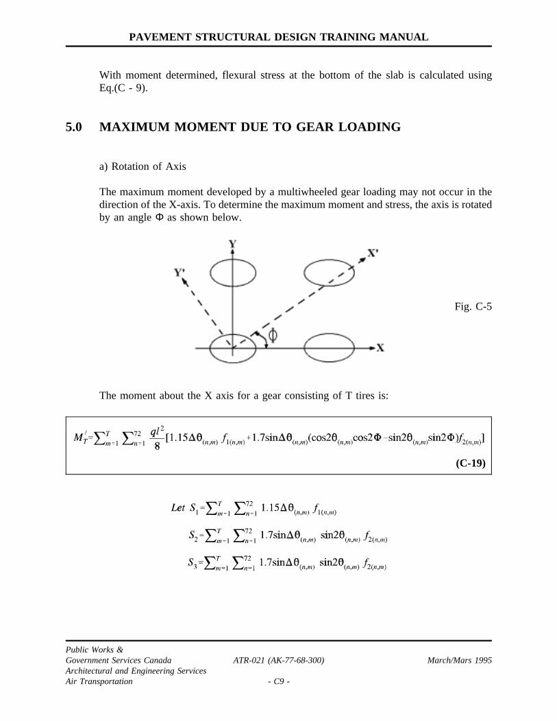
PAVEMENT STRUCTURAL DESIGN TRAINING MANUAL
With moment determined, flexural stress at the bottom of the slab is calculated usingEq.(C - 9).
5.0 MAXIMUM MOMENT DUE TO GEAR LOADING
a) Rotation of Axis
The maximum moment developed by a multiwheeled gear loading may not occur in thedirection of the X-axis. To determine the maximum moment and stress, the axis is rotatedby an angleΦ as shown below.
Fig. C-5
The moment about the X axis for a gear consisting of T tires is:
(C-19)
Public Works &Government Services Canada ATR-021 (AK-77-68-300) March/Mars 1995Architectural and Engineering ServicesAir Transportation - C9 -
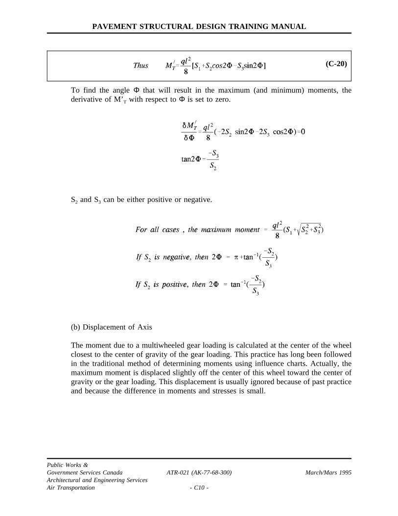
PAVEMENT STRUCTURAL DESIGN TRAINING MANUAL
To find the angleΦ that will result in the maximum (and minimum) moments, the
(C-20)
derivative of M’T with respect toΦ is set to zero.
S2 and S3 can be either positive or negative.
(b) Displacement of Axis
The moment due to a multiwheeled gear loading is calculated at the center of the wheelclosest to the center of gravity of the gear loading. This practice has long been followedin the traditional method of determining moments using influence charts. Actually, themaximum moment is displaced slightly off the center of this wheel toward the center ofgravity or the gear loading. This displacement is usually ignored because of past practiceand because the difference in moments and stresses is small.
Public Works &Government Services Canada ATR-021 (AK-77-68-300) March/Mars 1995Architectural and Engineering ServicesAir Transportation - C10 -

PAVEMENT STRUCTURAL DESIGN TRAINING MANUAL
APPENDIX D
FLEXIBLE PAVEMENT DESIGN
COMPUTER PROGRAM
Public Works &Government Services Canada ATR-021 (AK-77-68-300) March/Mars 1995Architectural and Engineering ServicesAir Transportation - D1 -

PAVEMENT STRUCTURAL DESIGN TRAINING MANUAL
"FLEXIBLE" is a BASIC program written using Microsoft QuickBasic 4.5 and can beused on any IBM-PC computer. The program may be modified for use with othermachines or input/output modes. Refer to the following pages for an example programrun and output which is briefly described below.
Once the program has been loaded into the system, it will then prompt the user to enterthe necessary data.
INPUT 1: Allows the user to identify the aircraft or ground vehicle with a maximumof 30 characters.
INPUT 2: Aircraft gross weight in kN.
INPUT 3: The percent of the gross weight on the gear in question.
INPUT 4: The number of wheels in the gear.
INPUT 5: The tire pressure in MPa.
INPUT 6: Allows the user to differentiate between an aircraft or a ground vehiclerun.
INPUT 7: The program will then prompt the user to determine whether a hardcopyprintout of the results is required.
INPUT 8: The gear wheel co-ordinates. The (X,Y) co-ordinates in cm of the wheelcentres inputed one pair at a time. In giving the wheel co-ordinates, thegear must be oriented so that its rolling axis is parallel to the X-axis(Figure D-1). Neither the order in which the wheels are identified nor thelocation of the origin of the axes is critical. However, the wheel co-ordinates will be identified in the same manner in the output.
Normally the gear in question will be one of the main gears. If the gear load is known,it may be used in place of gross weight and 100% used as percent of load on the maingear.
By pressing F10 the program should now execute and produce the output shown in thefollowing pages. At the end of the run, the user may re-run the program with a new grossweight but with the other input values remaining the same.For the design/evaluation of roads and carparks, the ground vehicle option is chosen ininput 6. The output will then contain the subgrade bearing strength values required foroverload ratios of 0.625, 1.00, 1.25, 1.50 and 2.00 as shown by the example in thefollowing pages.
Public Works &Government Services Canada ATR-021 (AK-77-68-300) March/Mars 1995Architectural and Engineering ServicesAir Transportation - D2 -

PAVEMENT STRUCTURAL DESIGN TRAINING MANUAL
FIGURE D-1 - ORIENTATION OF AIRCRAFT GEAR
Public Works &Government Services Canada ATR-021 (AK-77-68-300) March/Mars 1995Architectural and Engineering ServicesAir Transportation - D3 -
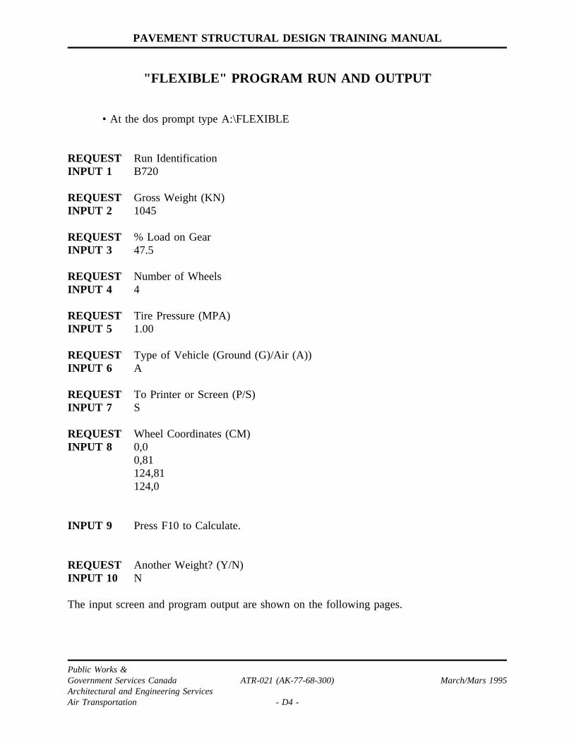
PAVEMENT STRUCTURAL DESIGN TRAINING MANUAL
"FLEXIBLE" PROGRAM RUN AND OUTPUT
• At the dos prompt type A:\FLEXIBLE
REQUEST Run IdentificationINPUT 1 B720
REQUEST Gross Weight (KN)INPUT 2 1045
REQUEST % Load on GearINPUT 3 47.5
REQUEST Number of WheelsINPUT 4 4
REQUEST Tire Pressure (MPA)INPUT 5 1.00
REQUEST Type of Vehicle (Ground (G)/Air (A))INPUT 6 A
REQUEST To Printer or Screen (P/S)INPUT 7 S
REQUEST Wheel Coordinates (CM)INPUT 8 0,0
0,81124,81124,0
INPUT 9 Press F10 to Calculate.
REQUEST Another Weight? (Y/N)INPUT 10 N
The input screen and program output are shown on the following pages.
Public Works &Government Services Canada ATR-021 (AK-77-68-300) March/Mars 1995Architectural and Engineering ServicesAir Transportation - D4 -

PAVEMENT STRUCTURAL DESIGN TRAINING MANUAL
INPUT SCREEN
FLEXIBLE PAVEMENT DESIGN
Run Identification : B720Gross Weight (KN): 1045 % Load on Gear: 47.5
Number of Wheels: 4 Tire Pressure (MPA) : 1.00Type of Vehicle (Ground (G)/Air (A)): A To Printer Or Screen(P/S)
Wheel Coordinate (CM): Wheel Num: X: 0 Y: 64
1: 0 02: 0 813: 124 814: 124 0
[SF4]-Quit [F10]-Calculate [Esc]-Reset
Public Works &Government Services Canada ATR-021 (AK-77-68-300) March/Mars 1995Architectural and Engineering ServicesAir Transportation - D5 -
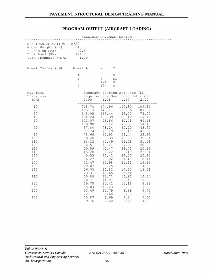
PAVEMENT STRUCTURAL DESIGN TRAINING MANUAL
PROGRAM OUTPUT (AIRCRAFT LOADING)
FLEXIBLE PAVEMENT DESIGN**********************************************************************
RUN IDENTIFICATION : B720Gross Weight (KN) : 1045.0% Load on Gear : 47.5Tire Load (KN) : 124.1Tire Pressure (MPA): 1.00
Wheel Coords (CM) : Wheel # X Y
1 0 02 0 813 124 814 124 0
Pavement Subgrade Bearing Strength (KN)Thickness Required For Over Load Ratio Of
(CM) 1.00 1.25 1.50 2.00======================================
10 218.70 174.96 145.80 109.3520 175.13 140.11 116.76 87.5730 148.05 118.44 98.70 74.0240 134.24 107.39 89.49 67.1250 121.07 96.86 80.71 60.5360 108.90 87.12 72.60 54.4570 97.80 78.24 65.20 48.9080 87.74 70.19 58.49 43.8790 78.66 62.93 52.44 39.33
100 70.48 56.38 46.98 35.24110 63.12 50.49 42.08 31.56120 56.51 45.21 37.68 28.26130 50.59 40.47 33.73 25.29140 45.28 36.22 30.19 22.64150 40.53 32.42 27.02 20.26160 36.27 29.02 24.18 18.14170 32.47 25.98 21.65 16.23180 29.07 23.25 19.38 14.53190 26.03 20.82 17.35 13.01200 23.31 18.65 15.54 11.66210 20.88 16.71 13.92 10.44220 18.71 14.97 12.48 9.36230 16.78 13.42 11.18 8.39240 15.04 12.03 10.03 7.52250 13.49 10.79 8.99 6.75260 12.11 9.68 8.07 6.05270 10.87 8.69 7.24 5.43280 9.76 7.80 6.50 4.88
Public Works &Government Services Canada ATR-021 (AK-77-68-300) March/Mars 1995Architectural and Engineering ServicesAir Transportation - D6 -

PAVEMENT STRUCTURAL DESIGN TRAINING MANUAL
PROGRAM OUTPUT (GROUND VEHICLE LOADING)
FLEXIBLE PAVEMENT DESIGN**********************************************************************RUN IDENTIFICATION : CRASH RESCUE VEHICLEGross Weight (KN) : 66.0% Load on Gear : 28.0Tire Load (KN) : 18.5Tire Pressure (MPA): 0.31
Wheel Coords (CM) : Wheel # X Y
0 0
Pavement Subgrade Bearing Strength (KN)Thickness Required For Over Load Ratio Of
(CM) 0.625 1.00 1.25 1.50 2.00==============================================
10 75.62 47.26 37.81 31.51 23.6320 57.89 36.18 28.95 24.12 18.0930 44.32 27.70 22.16 18.46 13.8540 33.92 21.20 16.96 14.14 10.6050 25.97 16.23 12.98 10.82 8.1260 19.88 12.42 9.94 8.28 6.2170 15.22 9.51 7.61 6.34 4.76
Public Works &Government Services Canada ATR-021 (AK-77-68-300) March/Mars 1995Architectural and Engineering ServicesAir Transportation - D7 -

PAVEMENT STRUCTURAL DESIGN TRAINING MANUAL
"FLEXIBLE" PROGRAM LISTING
’************************************************************************’* *’* Program Name: FLEXIBLE.BAS *’* Purpose.....: This program is for flexible pavement design according *’* to Transport Canada practices. Questions regarding *’* this program should be directed to AKPB. *’* Author......: AKPB *’* Date........: Feb 1987 *’* Language....: Hewlett Packard Basic *’* *’************************************************************************’* Compile Instructions: *’* *’* BC D:\QB40\SRC\FLEXIBLE.BAS /E/X/O; *’* Link /EX/NOE FLEXIBLE , D:\EXE\FLEXIBLE.EXE, , ALL.LIB; *’* *’************************************************************************’* *’* Modification History: *’* *’* Description of Change: *’* *’* July 88 - Capt R.H.J. Boisjoli *’* *’* Air Command Headquarters Winnipeg 895-5869 *’* *’* Translated to Microsoft Quick Basic 4.0. *’* This will allow the program to run on MSDOS *’* computers. *’* *’* February 92 - Marc Turpin *’* *’* PWC/A&ES/AIR TRANSPORTATION HQ 990-3780 *’* *’* Upgraded to Microsoft Quick Basic 4.5. *’* Corrected Errors (in SUB Calculate): *’* *’* -Change Xd% to Xd# in line 35 *’* -Change Xs% to Xs# in line 36 *’* -Change NumWhls% to N1% in line 62 *’* -Change "<" to ">" in line 66 *’* *’************************************************************************
CONST IDRow = 5, IDCol = 24, IDLen = 30 ’ Scrn row and col and len forIdent$CONST GWRow = 7, GWCol = 24, GWLen = 6 ’ Scrn row and col and len forGRWght#CONST LGRow = 7, LGCol = 55, LGLen = 5 ’ Scrn row and col and len forPcntLoad#CONST NWRow = 9, NWCol = 24, NWLen = 2 ’ Scrn row and col and len forNumWhls%CONST TPRow = 9, TPCol = 55, TPLen = 6 ’ Scrn row and col and len forTirePress#CONST VTRow = 11, VTCol = 44, VTLe n = 1 ’ Scrn row and col and len forVehType$CONST WXRow = 15, WXCol = 49, WXLen = 4 ’ Scrn row and col and len forWheelX%
Public Works &Government Services Canada ATR-021 (AK-77-68-300) March/Mars 1995Architectural and Engineering ServicesAir Transportation - D8 -

PAVEMENT STRUCTURAL DESIGN TRAINING MANUAL
CONST WYRow = 15, WYCol = 58, WYLen = 4 ’ Scrn row and col and len forWheelY%CONST PSRow = 11, PSCol = 76, PSLen = 1 ’ Scrn row and col and len forPrintScrnCONST ReportFileName = "REPORT.FIL" ’ Temp report file name
DECLARE SUB Calculate (Ident$, GRWght&, PcntLoad#, NumWhls%, TirePress#,VehType$)DECLARE SUB Credit ()DECLARE SUB DrawScreen ()DECLARE SUB EditFld (CurrFld$, ValidChars$, StRow%, StCol%, FldType%,FldLen%, ExitKey$)DECLARE SUB Frame (ULRow%, ULCol%, LRRow%, LRCol%, LineType%)DECLARE SUB InputData (Ident$, GRWght&, PcntLoad#, NumWhls%, TirePress#,VehType$, ExitKey$)DECLARE SUB Page ()
DIM SHARED Esc AS STRING * 1 ’The Escape keyDIM SHARED BS AS STRING * 1 ’The back space keyDIM SHARED ABORT AS STRING * 2 ’The shift F4 keyDIM SHARED Retrn AS STRING * 1 ’The Return or Enter keyDIM SHARED CrsrRight AS STRING * 2 ’The right arrow keyDIM SHARED CrsrLeft AS STRING * 2 ’The left arrow keyDIM SHARED CrsrDown AS STRING * 2 ’The down arrow keyDIM SHARED CrsrUp AS STRING * 2 ’The up arrow keyDIM SHARED PF10 AS STRING * 2DIM SHARED PrtScrn AS STRING * 1DIM SHARED WheelX%(1 TO 12)DIM SHARED WheelY%(1 TO 12)DIM SHARED SBRarray#(1 TO 70)DIM SHARED SBR.625array#(1 TO 70)DIM SHARED SBR1.25array#(1 TO 70)DIM SHARED SBR1.50array#(1 TO 70)DIM SHARED SBR2.00array#(1 TO 70)DIM SHARED GRWght&DIM SHARED Ident$DIM SHARED PcntLoad#DIM SHARED TireLoad#DIM SHARED TirePress#DIM SHARED NumWhls%DIM SHARED ReportFile AS STRINGDIM SHARED FileNum AS INTEGERDIM SHARED PageLen AS INTEGER
’’************************************************************************’* *’* Main line. *’* *’************************************************************************
BS = CHR$(8)Esc = CHR$(27)ABORT = CHR$(0) + CHR$(87)Retrn = CHR$(13)CrsrRight = CHR$(0) + CHR$(77)CrsrLeft = CHR$(0) + CHR$(75)CrsrUp = CHR$(0) + CHR$(72)CrsrDown = CHR$(0) + CHR$(80)PF10 = CHR$(0) + CHR$(68)
Public Works &Government Services Canada ATR-021 (AK-77-68-300) March/Mars 1995Architectural and Engineering ServicesAir Transportation - D9 -

PAVEMENT STRUCTURAL DESIGN TRAINING MANUAL
ExitKey$ = EscPrtScrn = "S" ’ Set report to screenCreditON ERROR GOTO ErrHandlerDO
FileNum = FREEFILEInputData Ident$, GRWght&, PcntLoad#, NumWhls%, TirePress#, VehType$,
ExitKey$IF ExitKey$ = PF10 THEN
IF PrtScrn = "S" THENCLSReportFile = "SCRN:" + ReportFileNamePageLen = 23
ELSEReportFile = "LPT1:"’ + ReportFileNamePageLen = 54
END IFCalculate Ident$, GRWght&, PcntLoad#, NumWhls%, TirePress#, VehType$IF PrtScrn = "S" THEN
LOCATE 25, 2PRINT "Press any key to continue...";WHILE INKEY$ = ""WENDDrawScreen
END IFLOCATE 23, 1PRINT "Another Weight ? (Y/N)";LOCATE 23, 27, 1Ans$ = ""WHILE Ans$ = ""
Ans$ = INKEY$IF UCASE$(Ans$) <> "Y" AND UCASE$(Ans$) <> "N" THEN
Ans$ = ""END IF
WENDIF UCASE$(Ans$) = "Y" THEN
ExitKey$ = ""GRWght& = 0LOCATE GWRow, GWColPRINT "_____ ";LOCATE 23, 1PRINT " ";
END IFEND IF
LOOP UNTIL GRWght& > 0 OR ExitKey$ = ABORTCLSEND
ErrHandler:Errr% = ERRLOCATE 22, 1BEEPSELECT CASE Errr%
CASE 24, 25PRINT "Printer Not Ready. Please Check It.";
CASE 27PRINT "Printer Out Of Paper. Please Reload.";
CASE ELSEPRINT "Unknown Error." + STR$(Errr%)
END SELECTLOCATE 23, 1
Public Works &Government Services Canada ATR-021 (AK-77-68-300) March/Mars 1995Architectural and Engineering ServicesAir Transportation - D10 -

PAVEMENT STRUCTURAL DESIGN TRAINING MANUAL
PRINT " Press any key to continue...";WHILE INKEY$ = ""WENDLOCATE 22, 1PRINT " ";LOCATE 23, 1PRINT " ";IF ((Errr% = 25) OR (Errr% = 27) OR (Errr% = 24)) THEN
Errr% = 0RESUME
ELSERESUME NEXT
END IFEND
’’************************************************************************’* *’* This procedure calculates and prints the appropriate values. Many *’* of the variables do not have meaningful names. The names used in *’* in the original Hewlett-Packard program were retained since there *’* was no way of telling what they stood for. *’* *’************************************************************************’SUB Calculate (Ident$, GRWght&, PcntLoad#, NumWhls%, TirePress#, VehType$)
’************************************************************************’* *’* Calculate tire load and print titles. *’* *’************************************************************************’
TireLoad# = GRWght& * PcntLoad# / (100 * NumWhls%)FileNum = FREEFILEOPEN ReportFile FOR OUTPUT AS FileNumPageNumLines% = 16 + NumWhls%
’’************************************************************************’* *’* Multiple wheel centre - geometric. *’* *’************************************************************************’
IF PrtScrn = "P" THENLOCATE 23, 1PRINT "Working...";
END IFXd# = 1000Xs# = 0N1% = NumWhls% - 1IF N1% > 0 THEN
Xg% = 0Yg% = 0FOR Count% = 1 TO NumWhls%
Xg% = Xg% + WheelX%(Count%)Yg% = Yg% + WheelY%(Count%)
NEXT Count%Xg% = Xg% / NumWhls%Yg% = Yg% / NumWhls%
Public Works &Government Services Canada ATR-021 (AK-77-68-300) March/Mars 1995Architectural and Engineering ServicesAir Transportation - D11 -

PAVEMENT STRUCTURAL DESIGN TRAINING MANUAL
Ref# = 1000# ’ Closest wheelFOR Count% = 1 TO NumWhls%
Z# = SQR((Xg% - WheelX%(Count%) ) ^ 2 + (Yg% - WheelY%(Count%)) ^ 2)IF Ref# > Z# THEN
Ref# = Z#Xref% = WheelX%(Count%)Yref% = WheelY%(Count%)
END IFNEXT Count%FOR Count% = 1 TO NumWhls% ’ C/C spacing
Z# = SQR((Xref% - WheelX%(Count%) ) ^ 2 + (Yref% - WheelY%(Count%))^ 2)
IF Xs# < Z# THENXs# = Z#
END IFNEXT Count%FOR Count% = 1 TO N1% ’ Clear spacing
N2% = Count% + 1FOR Count2% = N2% TO NumWhls%
Z# = SQR((WheelX%(Count%) - WheelX%(Count2%) ) ^ 2 +(WheelY%(Count%) - WheelY%(Count2%)) ^ 2)
IF (Xd# - Z#) > 0 THENXd# = Z#Yy% = WheelY%(Count%) - WheelY%(Count2%)
END IFNEXT Count2%
NEXT Count%Xd# = Xd# - .8298 * SQR(10# * TireLoad# / TirePress#)IF Yy% = 0 THEN
Xd# = Xd# - .5532 * SQR(10# * TireLoad# / TirePress#)END IFZ# = NumWhls% ’ EWSLM% = 1
END IFCount% = 10
’’************************************************************************’* *’* This section calculates and prints the subgrade bearing strength. *’* *’************************************************************************’
DOT# = Count%IF T# - (Xd# / 2#) <= 0 THEN
Xp# = TireLoad# ’ fo r T < D / 2ELSE
IF T# - (2# * Xs#) >= 0 THENXp# = Z# * TireLoad# ’ fo r T > 2S
ELSE ’ D/ 2 < T < 2SXp# = TireLoad# * (2# * T# / Xd#) ^ ((LOG(Z#) / LOG(10#)) /
(LOG(4# * Xs# / Xd#) / LOG(10#)))END IF
END IFArea# = 10 * Xp# / TirePress#IF Area# < 100 THEN ’Area# > 8000# OR
Count% = 710PRINT #FileNum, " Contact Area Outside of Empirical
Relationship"NumLines% = NumLines% + 1
ELSE
Public Works &Government Services Canada ATR-021 (AK-77-68-300) March/Mars 1995Architectural and Engineering ServicesAir Transportation - D12 -
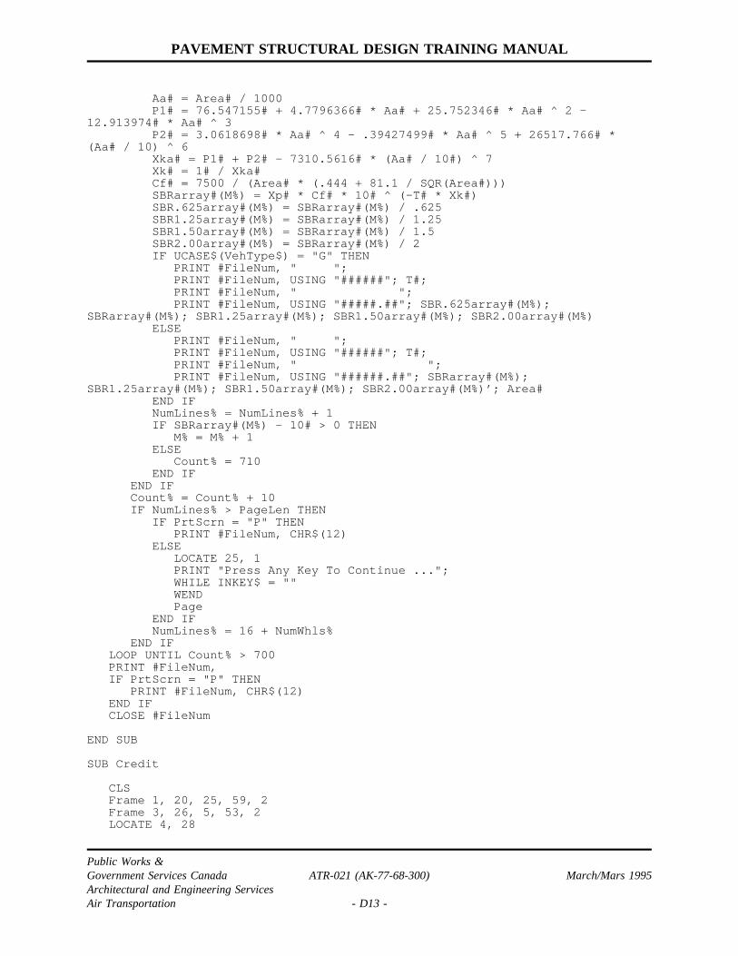
PAVEMENT STRUCTURAL DESIGN TRAINING MANUAL
Aa# = Area# / 1000P1# = 76.547155# + 4.7796366# * Aa# + 25.752346# * Aa # ^ 2 -
12.913974# * Aa# ^ 3P2# = 3.0618698# * Aa # ^ 4 - .39427499# * Aa # ^ 5 + 26517.766# *
(Aa# / 10) ^ 6Xka# = P1# + P2# - 7310.5616# * (Aa# / 10#) ^ 7Xk# = 1# / Xka#Cf# = 7500 / (Area# * (.444 + 81.1 / SQR(Area#)))SBRarray#(M%) = Xp# * Cf# * 10# ^ (-T# * Xk#)SBR.625array#(M%) = SBRarray#(M%) / .625SBR1.25array#(M%) = SBRarray#(M%) / 1.25SBR1.50array#(M%) = SBRarray#(M%) / 1.5SBR2.00array#(M%) = SBRarray#(M%) / 2IF UCASE$(VehType$) = "G" THEN
PRINT #FileNum, " ";PRINT #FileNum, USING "######"; T#;PRINT #FileNum, " ";PRINT #FileNum, USING "#####.##"; SBR.625array#(M%);
SBRarray#(M%); SBR1.25array#(M%); SBR1.50array#(M%); SBR2.00array#(M%)ELSE
PRINT #FileNum, " ";PRINT #FileNum, USING "######"; T#;PRINT #FileNum, " ";PRINT #FileNum, USING "######.##"; SBRarray#(M%);
SBR1.25array#(M%); SBR1.50array#(M%); SBR2.00array#(M%)’; Area#END IFNumLines% = NumLines% + 1IF SBRarray#(M%) - 10 # > 0 THEN
M% = M% + 1ELSE
Count% = 710END IF
END IFCount% = Count% + 10IF NumLines% > PageLen THEN
IF PrtScrn = "P" THENPRINT #FileNum, CHR$(12)
ELSELOCATE 25, 1PRINT "Press Any Key To Continue ...";WHILE INKEY$ = ""WENDPage
END IFNumLines% = 16 + NumWhls%
END IFLOOP UNTIL Count% > 700PRINT #FileNum,IF PrtScrn = "P" THEN
PRINT #FileNum, CHR$(12)END IFCLOSE #FileNum
END SUB
SUB Credit
CLSFrame 1, 20, 25, 59, 2Frame 3, 26, 5, 53, 2LOCATE 4, 28
Public Works &Government Services Canada ATR-021 (AK-77-68-300) March/Mars 1995Architectural and Engineering ServicesAir Transportation - D13 -

PAVEMENT STRUCTURAL DESIGN TRAINING MANUAL
PRINT "FLEXIBLE PAVEMENT DESIGN"Frame 12, 26, 16, 53, 2LOCATE 7, 28PRINT "MICROSOFT QUICKBASIC 4.5"LOCATE 13, 30PRINT "PUBLIC WORKS CANADA"LOCATE 14, 34PRINT "A&E SERVICES"LOCATE 15, 31PRINT "AIR TRANSPORTATION"LOCATE 18, 33PRINT "FEBRUARY 1992"LOCATE 23, 25PRINT "Press any key to continue...";WHILE INKEY$ = ""WEND
END SUB
’’************************************************************************’* *’* This procedure displays the input screen. *’* *’************************************************************************’SUB DrawScreen
CLSPRINT " "; SPACE$(22); "FLEXIBLE PAVEMENT DESIGN"Frame 3, 1, 13, 80, 2LOCATE 5, 4PRINT "Run Identification: ______________________________"LOCATE 7, 5PRINT "Gross Weight (KN): _____"; SPACE$(10); "% Load on Gear: _____"LOCATE 9, 6PRINT "Number of Wheels: __"; SPACE$(8); "Tire Pressure (MPA): ______"LOCATE 11, 6PRINT "Type of Vehicle (Ground (G)/Air (A)): _ To Printer Or Screen
(P/S) _"LOCATE 15, 7PRINT "Wheel Coordinates (CM): Wheel Num: __ X: ____ Y: ____"Frame 16, 38, 24, 63, 2LOCATE 25, 5PRINT SPACE$(15); "[SF4]-Quit [F10]-Calculate [Esc]-Reset";
END SUB
’’************************************************************************’* *’* This procedure does the actual input of data for all the fields. *’* The type of field will decide what characters will be acceptable. *’* *’************************************************************************’SUB EditFld (CurrFld$, ValidChars$, StRow%, StCol%, FldType%, FldLen%,ExitKey$)
SELECT CASE FldType% ’ Set up valid characters for field typeCASE 1 ’ String
ValidChars$ = "
Public Works &Government Services Canada ATR-021 (AK-77-68-300) March/Mars 1995Architectural and Engineering ServicesAir Transportation - D14 -

PAVEMENT STRUCTURAL DESIGN TRAINING MANUAL
ABCDEFGHIJKLMNOPQRTSUVWXYZ1234567890-=‘~!@#$%^%^&*()_+<>?,./;’[]\|}{":CASE 2 ’ Integer
ValidChars$ = "1234567890-+"CASE 3 ’ Float
ValidChars$ = "1234567890.EeDd+-"CASE ELSE ’ Any other values, accept the values passed in
ValidChars$END SELECTCount% = 0LenFld% = LEN(CurrFld$)IF LenFld% < FldLen% THEN ’ Fill field with _ to max length
CurrFld$ = CurrFld$ + STRING$(FldLen% - LenFld%, "_")END IFLOCATE StRow%, StCol%PRINT CurrFld$ExitKey$ = ""DO
LOCATE StRow%, StCol% + Count%, 1, 5, 7InChar$ = ""WHILE InChar$ = ""
InChar$ = INKEY$ ’ wait for and read keystrokeWENDIF INSTR(ValidChars$, UCASE$(InChar$) ) > 0 THEN
IF Count% < FldLen% THEN ’ if valid character insert in fieldMID$(CurrFld$, Count% + 1, 1) = InChar$PRINT InChar$;
END IFIF Count% < FldLen% THEN
Count% = Count% + 1 ’ check to ensure not at endELSE
BEEPEND IF
ELSE ’ this is an extended keySELECT CASE InChar$
CASE CrsrLeft ’ left arrow keyIF Count % > 0 THEN
Count% = Count% - 1ELSE
BEEPEND IF
CASE CrsrRight ’ right arrow keyIF Count% < FldLen% THEN
Count% = Count% + 1ELSE
BEEPEND IF
’CASE BS ’ back space
IF Count % > 0 THENIF Count% = FldLen% THEN
MID$(CurrFld$, Count%, 1 ) = " "ELSE
MID$(CurrFld$, Count%, FldLen% - Count% + 1) =MID$(CurrFld$, Count% + 1, FldLen% - Count%)
END IFCurrFld$ = CurrFld $ + " "LOCATE StRow%, StCol%PRINT LEFT$(CurrFld$, FldLen%)Count% = Count% - 1
ELSEBEEP
Public Works &Government Services Canada ATR-021 (AK-77-68-300) March/Mars 1995Architectural and Engineering ServicesAir Transportation - D15 -

PAVEMENT STRUCTURAL DESIGN TRAINING MANUAL
END IFCASE Esc, ABORT, CrsrUp, CrsrDown, Retrn, PF10
ExitKey$ = InChar$ ’ Escape, up arrow, down arrow, Return,Shift F4, F10
CASE ELSEBEEP
END SELECTEND IF
LOOP UNTIL ExitKey$ <> ""Count% = FldLen%WHILE MID$(CurrFld$, Count%, 1) = "_" AND Count% > 1
Count% = Count% - 1WENDIF Count % = 1 AND LEFT$(CurrFld$, 1) = "_" THEN
CurrFld$ = ""ELSE
CurrFld$ = LEFT$(CurrFld$, Count%)END IF
END SUB
’’************************************************************************’* *’* This procedure draws a line frame on the screen starting at ULRow%, *’* ULCol% down and across to LRRow%, LRCol%. If LineType % = 1 then a *’* single line is drawn if it i s 2 a double line frame is drawn. *’* *’************************************************************************
’SUB Frame (ULRow%, ULCol%, LRRow%, LRCol%, LineType%)
OldY% = POS(1)OldX% = CSRLINFrameWidth% = LRCol% - ULCol% - 1FrameHeight% = LRRow% - ULRow% - 1Offset% = ULCol% - 1SELECT CASE LineType%
CASE 1URCorner $ = " "LLCorner $ = " "HorizLine $ = " "ULCorner $ = " "VertLine $ = " "LRCorner $ = " "
CASE 2URCorner $ = " "VertLine $ = " "LLCorner $ = " "ULCorner $ = " "LRCorner $ = " "HorizLine $ = " "
END SELECTLOCATE ULRow%, ULCol%PRINT ULCorner$; STRING$(FrameWidth%, HorizLine$); URCorner$;FOR Count% = 1 TO FrameHeight%
LOCATE ULRow% + Count%, ULCol%PRINT VertLine$; SPACE$(FrameWidth%); VertLine$;
NEXT Count%LOCATE LRRow%, ULCol%
Public Works &Government Services Canada ATR-021 (AK-77-68-300) March/Mars 1995Architectural and Engineering ServicesAir Transportation - D16 -

PAVEMENT STRUCTURAL DESIGN TRAINING MANUAL
PRINT LLCorner$; STRING$(FrameWidth%, HorizLine$); LRCorner$;LOCATE OldY%, OldX%
END SUB
’’************************************************************************’* *’* This procedure controls the input of data. The Ident field is *’* entered. A value must be entered before moving to the next field. *’* Once values have been entered the user may move to any field to *’* the previously entered value. EditFld is called to accept data for *’* all fields. The user must press SPF4 or PF10 to exit this routine. *’* *’************************************************************************’SUB InputData (Ident$, GRWght&, PcntLoad#, NumWhls%, TirePress#, VehType$,ExitKey$)
CurrFld% = 1DO
DOIF ExitKey$ = Esc THEN ’ Re-initialize variables
Ident$ = ""GRWght& = 0PcntLoad# = 0#NumWhls% = 0TirePress# = 0#VehType$ = ""WhlCnt% = 1CurrFld% = 1DrawScreen
END IFSELECT CASE CurrFld% ’ set up parameters to pass to EditFld
CASE 1 ’ Ident fieldCurrField$ = Ident$StRow% = IDRowStCol% = IDColFldLen% = IDLenFldType% = 1
CASE 2 ’ Gross WeightIF GRWght& <> 0& THEN
CurrField$ = LTRIM$(STR$(GRWght&))ELSE
CurrField$ = "0"END IFStRow% = GWRowStCol% = GWColFldLen% = GWLenFldType% = 2
CASE 3 ’ Percent load on wheelsIF PcntLoad# <> 0# THEN
CurrField$ = LTRIM$(STR$(PcntLoad#))ELSE
CurrField$ = "0"END IFStRow% = LGRowStCol% = LGColFldLen% = LGLenFldType% = 3
’
Public Works &Government Services Canada ATR-021 (AK-77-68-300) March/Mars 1995Architectural and Engineering ServicesAir Transportation - D17 -

PAVEMENT STRUCTURAL DESIGN TRAINING MANUAL
CASE 4 ’ Number of wheelsIF NumWhls% <> 0 THEN
CurrField$ = LTRIM$(STR$(NumWhls%))ELSE
CurrField$ = "0"END IFStRow% = NWRowStCol% = NWColFldLen% = NWLenFldType% = 2WhlCnt% = 1
CASE 5 ’ Tire pressureIF TirePress# <> 0# THEN
CurrField$ = LTRIM$(STR$(TirePress#))ELSE
CurrField$ = "0"END IFStRow% = TPRowStCol% = TPColFldLen% = TPLenFldType% = 3
CASE 6 ’ Vehicle typeCurrField$ = VehType$StRow% = VTRowStCol% = VTColFldLen% = VTLenFldType% = 4ValidChars$ = "GA" ’ only characters that will be accepted
CASE 7CurrField$ = PrtScrnStRow% = PSRowStCol% = PSColFldLen% = PSLenFldType% = 4ValidChars$ = "PS"
CASE 8 ’ Wheel X coordIF NumWhls % = 0 THEN
BEEP ’ Must enter number of wheel beforeCurrFld% = 4 ’ entering coordinatesCurrField$ = "0"StRow% = NWRowStCol% = NWColFldLen% = NWLenFldType% = 2WhlCnt% = 1
ELSEIF WheelX%(WhlCnt%) <> 0 THEN
CurrField$ = LTRIM$(STR$(WheelX%(WhlCnt%)))ELSE
CurrField$ = "0"END IFLOCATE 15, 41PRINT WhlCnt%; " X: ";PRINT USING "####"; WheelX%(WhlCnt%);PRINT " Y: ";PRINT USING "####"; WheelY%(WhlCnt%);StRow% = WXRowStCol% = WXColFldLen% = WXLenFldType% = 2
END IF
Public Works &Government Services Canada ATR-021 (AK-77-68-300) March/Mars 1995Architectural and Engineering ServicesAir Transportation - D18 -

PAVEMENT STRUCTURAL DESIGN TRAINING MANUAL
’CASE 9 ’ Wheel Y coord
IF WheelY%(WhlCnt%) <> 0 THENCurrField$ = LTRIM$(STR$(WheelY%(WhlCnt%)))
ELSECurrField$ = "0"
END IFLOCATE 15, 41PRINT WhlCnt%; " X: ";PRINT USING "####"; WheelX%(WhlCnt%);PRINT " Y: ";PRINT USING "####"; WheelY%(WhlCnt%);StRow% = WYRowStCol% = WYColFldLen% = WYLenFldType% = 2
END SELECTCurrField$ = LEFT$(CurrField$, FldLen%)EditFld CurrField$, ValidChars$, StRow%, StCol%, FldType%, FldLen%,
ExitKey$LOOP UNTIL CurrField$ <> "" OR ExitKey$ = ABORTIF ExitKey$ <> Esc AND ExitKey$ <> ABORT THEN
SELECT CASE CurrFld% ’ Reassign CurrField to appropriatevariable
CASE 1Ident$ = CurrField$
CASE 2GRWght& = VAL(CurrField$)LOCATE GWRow, GWColPRINT USING "####.#"; GRWght&
CASE 3PcntLoad# = VAL(CurrField$)LOCATE LGRow, LGColPRINT USING "###.#"; PcntLoad#
CASE 4NumWhls% = VAL(CurrField$)LOCATE NWRow, NWColPRINT USING "##"; NumWhls%
CASE 5TirePress# = VAL(CurrField$)LOCATE TPRow, TPColPRINT USING "###.##"; TirePress#
CASE 6VehType$ = UCASE$(CurrField$)
CASE 7PrtScrn = UCASE$(CurrField$)
CASE 8WheelX%(WhlCnt%) = VAL(CurrField$)
CASE 9WheelY%(WhlCnt%) = VAL(CurrField$)IF WhlCnt % > 7 THEN
Start% = WhlCnt% - 6ELSE
Start% = 1END IFDispStart% = 1 ’ display wheel coords in windowFOR Count% = Start% TO WhlCnt%
LOCATE 16 + DispStart%, 40PRINT USING "###"; Count%;PRINT ": ";PRINT USING "###"; WheelX%(Count%);
Public Works &Government Services Canada ATR-021 (AK-77-68-300) March/Mars 1995Architectural and Engineering ServicesAir Transportation - D19 -
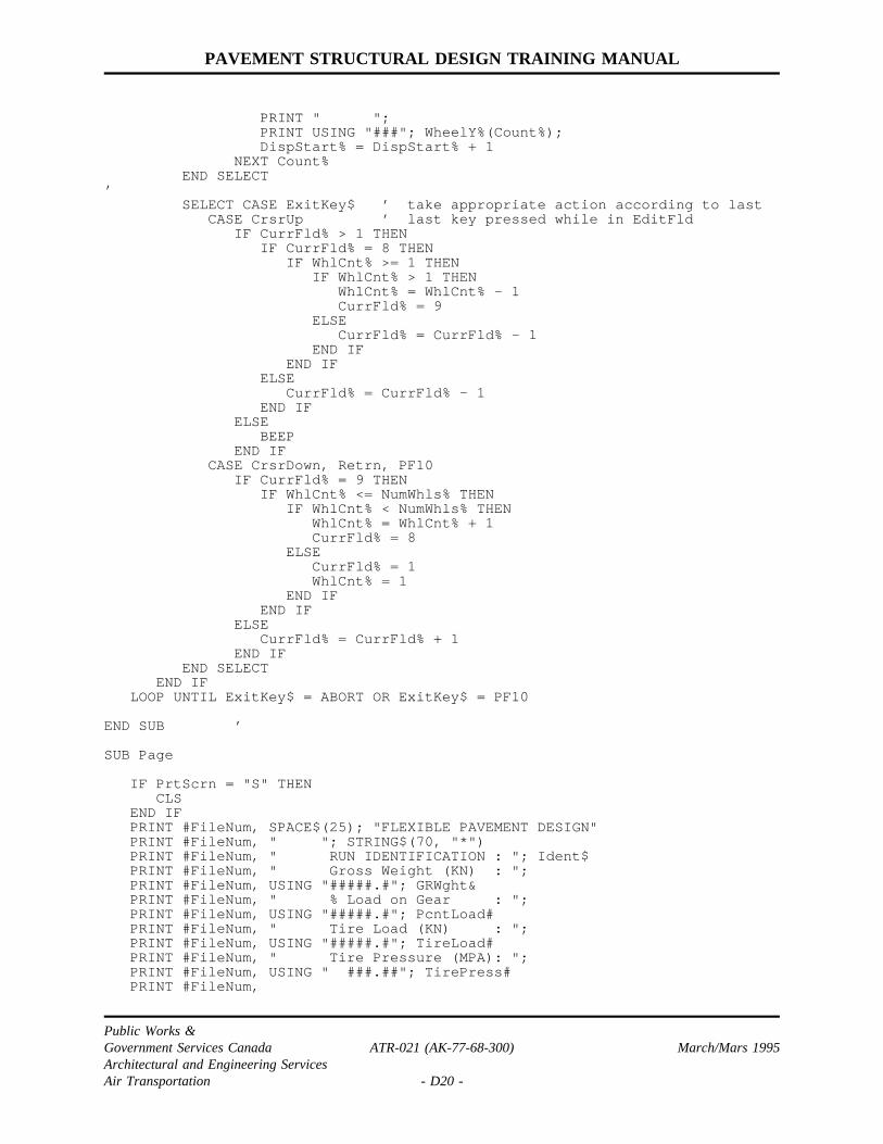
PAVEMENT STRUCTURAL DESIGN TRAINING MANUAL
PRINT " ";PRINT USING "###"; WheelY%(Count%);DispStart% = DispStart% + 1
NEXT Count%END SELECT
’SELECT CASE ExitKey$ ’ take appropriate action according to last
CASE CrsrUp ’ last key pressed while in EditFldIF CurrFld % > 1 THEN
IF CurrFld % = 8 THENIF WhlCnt% >= 1 THEN
IF WhlCnt % > 1 THENWhlCnt% = WhlCnt% - 1CurrFld% = 9
ELSECurrFld% = CurrFld% - 1
END IFEND IF
ELSECurrFld% = CurrFld% - 1
END IFELSE
BEEPEND IF
CASE CrsrDown, Retrn, PF10IF CurrFld % = 9 THEN
IF WhlCnt% <= NumWhls% THENIF WhlCnt% < NumWhls% THEN
WhlCnt% = WhlCnt% + 1CurrFld% = 8
ELSECurrFld% = 1WhlCnt% = 1
END IFEND IF
ELSECurrFld% = CurrFld% + 1
END IFEND SELECT
END IFLOOP UNTIL ExitKey$ = ABORT OR ExitKey$ = PF10
END SUB ’
SUB Page
IF PrtScrn = "S" THENCLS
END IFPRINT #FileNum, SPACE$(25); "FLEXIBLE PAVEMENT DESIGN"PRINT #FileNum, " "; STRING$(70, "*")PRINT #FileNum, " RUN IDENTIFICATION : "; Ident$PRINT #FileNum, " Gross Weight (KN) : ";PRINT #FileNum, USING "#####.#"; GRWght&PRINT #FileNum, " % Load on Gear : ";PRINT #FileNum, USING "#####.#"; PcntLoad#PRINT #FileNum, " Tire Load (KN) : ";PRINT #FileNum, USING "#####.#"; TireLoad#PRINT #FileNum, " Tire Pressure (MPA): ";PRINT #FileNum, USING " ###.##"; TirePress#PRINT #FileNum,
Public Works &Government Services Canada ATR-021 (AK-77-68-300) March/Mars 1995Architectural and Engineering ServicesAir Transportation - D20 -

PAVEMENT STRUCTURAL DESIGN TRAINING MANUAL
PRINT #FileNum,PRINT #FileNum, " Wheel Coords (CM) : Wheel # X Y"PRINT #FileNum,FOR Count% = 1 TO NumWhls%
PRINT #FileNum, SPACE$(29); Count%; " "; WheelX%(Count%); ""; WheelY%(Count%)
NEXT Count%PRINT #FileNum,IF UCASE$(VehType$) = "G" THEN
PRINT #FileNum, " Pavement"; SPACE$(15); " Subgrade BearingStrength (KN)"
PRINT #FileNum, " Thickness"; SPACE$(14); " Required For OverLoad Ratio Of"
PRINT #FileNum, " (CM) 0.625 1.00 1.251.50 2.00"
PRINT #FileNum, "==============================================="
ELSEPRINT #FileNum, " Pavement"; SPACE$(18); " Subgrade Bearing
Strength (KN)"PRINT #FileNum, " Thickness"; SPACE$(17); " Required For Over
Load Ratio Of"PRINT #FileNum, " (CM) 1.00 1.25
1.50 2.00"PRINT #FileNum, "
======================================"END IF
END SUB
Public Works &Government Services Canada ATR-021 (AK-77-68-300) March/Mars 1995Architectural and Engineering ServicesAir Transportation - D21 -

PAVEMENT STRUCTURAL DESIGN TRAINING MANUAL
APPENDIX E
RIGID PAVEMENT DESIGN
COMPUTER PROGRAM
Public Works &Government Services Canada ATR-021 (AK-77-68-300) March/Mars 1995Architectural and Engineering ServicesAir Transportation - E1 -

PAVEMENT STRUCTURAL DESIGN TRAINING MANUAL
"RIGID" is a BASIC program written using Microsoft QuickBasic 4.5 and can beused on any IBM-PC computer. The program may be modified for use with othermachines or input/output modes. Refer to the following pages for an exampleprogram run and output which is briefly described below.
Once the program has been loaded into the system, it will then prompt the user toenter the necessary data.
INPUT 1: Allows the user to identify the aircraft or ground vehicle with amaximum of 30 characters.
INPUT 2: Aircraft gross weight in kN.
INPUT 3: The percent of the gross weight on the gear in question.
INPUT 4: The number of wheels in the gear.
INPUT 5: The tire pressure in MPa.
INPUT 6: The program will then prompt the user to determine whether ahardcopy printout of the results is required.
INPUT 7: The gear wheel co-ordinates. The (X,Y) co-ordinates in cm of thewheel centres inputed one pair at a time. The first wheel shouldnormally be centred at (0,0) and other wheels identified so that thegear is oriented to roll in the X-axis direction as shown in figure D-1.
If the gear load is known, it may be used in place of gross weight and 100% used aspercent of load on the main gear.
By pressing F10 the program should now execute on the assumption that themaximum moment is at the origin. If other locations are to be tested, then the valuesfor Xo and Yo specified in the program listing may be changes accordingly.
The program will produce the output shown the following pages. A zero in the tableof slab thickness (h) versus bearing modulus (k) indicates either that the value for kis outside the range of 10 N/cm3 < k < 200 N/cm3 or that the value would resultfrom an extrapolation of the radius of relative stiffness versus moment curve.
The data may be used to plot graphs similar to Figure 3.10. By re-running at variousweights, data may be obtained to plot nomographs of the type contained in AK-68-16 "Pavement Design - Evaluation Charts for Selected Aircraft".
Public Works &Government Services Canada ATR-021 (AK-77-68-300) March/Mars 1995Architectural and Engineering ServicesAir Transportation - E2 -

PAVEMENT STRUCTURAL DESIGN TRAINING MANUAL
"RIGID" PROGRAM RUN AND OUTPUT
• At the dos prompt type A:\RIGID
REQUEST Aircraft NameINPUT 1 B720
REQUEST Gross Weight (KN)INPUT 2 1045
REQUEST % Load on GearINPUT 3 47.5
REQUEST Number of WheelsINPUT 4 4
REQUEST Tire Pressure (MPA)INPUT 5 1.00
REQUEST To Printer or Screen (P/S)INPUT 6 S
REQUEST Wheel Coordinates (CM)INPUT 7 0,0
0,81124,81124,0
INPUT 8 Press F10 to Calculate.
REQUEST Another Weight? (Y/N)INPUT 9 N
The input screen and program output are shown on the following pages.
Public Works &Government Services Canada ATR-021 (AK-77-68-300) March/Mars 1995Architectural and Engineering ServicesAir Transportation - E3 -

PAVEMENT STRUCTURAL DESIGN TRAINING MANUAL
INPUT SCREEN
RIGID PAVEMENT DESIGN
Aircraft Name : B720Gross Weight (KN): 1045 % Load on Gear: 47.5
Number of Wheels: 4 Tire Pressure (MPA) : 1.00Printer (P) or Screen (S): S
Wheel Coordinate (CM): Wheel Num: X: 124 Y: 0
1: 0 02: 0 813: 124 814: 124 0
[SF4]-Quit [F10]-Calculate [Esc]-Reset
Public Works &Government Services Canada ATR-021 (AK-77-68-300) March/Mars 1995Architectural and Engineering ServicesAir Transportation - E4 -

PAVEMENT STRUCTURAL DESIGN TRAINING MANUAL
"RIGID" PROGRAM OUTPUT
RIGID PAVEMENT DESIGN*************************************************************************Aircraft Name : B720Gross Weight (KN): 1045.0 % Load on Gear :47.5Wheel Load (KN) : 124.1 Tire Pressure (MPA): 1.00
Wheel Coords (CM): Wheel# X Y1 0.0 0.02 0.0 81.03 124.0 81.04 124.0 0.0
Origin: 0.0 0.0
Stiffness Moment Angle(CM) (NM) (Deg)
40 138.14 43.4080 285.29 59.53
120 421.33 61.20160 532.55 61.72200 624.25 61.96240 701.59 62.09
Slab Bearing Modulus-K(N/CM3) ForThickness(CM) Slab Stress (Mpa)
2.75 3.50 4.10 5.50========================================
12.5 0.00 0.00 0.00 155.2713.0 0.00 0.00 0.00 128.2513.5 0.00 0.00 0.00 107.2114.0 0.00 0.00 0.00 90.5314.5 0.00 0.00 0.00 77.1015.0 0.00 0.00 0.00 66.1215.5 0.00 0.00 173.56 57.0416.0 0.00 0.00 149.61 49.4316.5 0.00 0.00 129.85 42.9917.0 0.00 0.00 113.34 37.4817.5 0.00 180.70 99.42 32.7418.0 0.00 158.79 87.57 28.6318.5 0.00 140.20 77.39 25.0419.0 0.00 124.29 68.58 21.9019.5 0.00 110.56 60.90 19.1420.0 0.00 98.63 54.16 16.7020.5 0.00 88.19 48.21 14.5521.0 195.76 79.00 42.95 12.6621.5 176.04 70.87 38.26 10.9822.0 158.72 63.64 34.08 0.0022.5 143.42 57.18 30.33 0.0023.0 129.84 51.39 26.98 0.0023.5 117.73 46.18 23.96 0.0024.0 106.87 41.49 21.26 0.0024.5 97.11 37.25 18.83 0.0025.0 88.29 33.42 16.65 0.0023.5 117.73 46.18 23.96 0.0024.0 106.87 41.49 21.26 0.0024.5 97.11 37.25 18.83 0.00
Public Works &Government Services Canada ATR-021 (AK-77-68-300) March/Mars 1995Architectural and Engineering ServicesAir Transportation - E5 -

PAVEMENT STRUCTURAL DESIGN TRAINING MANUAL
"RIGID" PROGRAM OUTPUT (CONT’D)
25.0 88.29 33.42 16.65 0.0025.5 80.31 29.95 14.70 0.0026.0 73.05 26.81 12.95 0.0026.5 66.45 23.97 11.38 0.0027.0 60.43 21.39 0.00 0.0027.5 54.93 19.07 0.00 0.0028.0 49.91 16.97 0.00 0.0028.5 45.30 15.07 0.00 0.0029.0 41.09 13.36 0.00 0.0029.5 37.23 11.82 0.00 0.0030.0 33.70 10.44 0.00 0.0030.5 30.47 0.00 0.00 0.0031.0 27.51 0.00 0.00 0.0031.5 24.81 0.00 0.00 0.0032.0 22.35 0.00 0.00 0.0032.5 20.10 0.00 0.00 0.0033.0 18.05 0.00 0.00 0.0033.5 16.18 0.00 0.00 0.0034.0 14.49 0.00 0.00 0.0034.5 12.95 0.00 0.00 0.0035.0 11.56 0.00 0.00 0.0035.5 10.30 0.00 0.00 0.00
Public Works &Government Services Canada ATR-021 (AK-77-68-300) March/Mars 1995Architectural and Engineering ServicesAir Transportation - E6 -
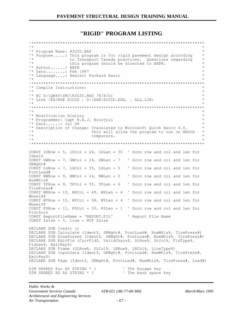
PAVEMENT STRUCTURAL DESIGN TRAINING MANUAL
"RIGID" PROGRAM LISTING
’************************************************************************’* *’* Program Name: RIGID.BAS *’* Purpose.....: This program is for rigid pavement design according *’* to Transport Canada practices. Questions regarding *’* this program should be directed to AKPB. *’* Author......: AKPB *’* Date........: Feb 1987 *’* Language....: Hewlett Packard Basic *’* *’************************************************************************’* Compile Instructions: *’* *’* BC D:\QB40\SRC\RIGID.BAS /E/X/O; *’* Link /EX/NOE RIGID , D:\EXE\RIGID.EXE, , ALL.LIB; *’* *’************************************************************************’* *’* Modification History *’* Programmer: Capt R.H.J. Boisjoli *’* Date......: Jul 88 *’* Description of Change: Translated to Microsoft Quick Basic 4.0. *’* This will allow the program to run on MSDOS *’* computers. *’* *’************************************************************************
CONST IDRow = 5, IDCol = 24, IDLen = 30 ’ Scrn row and col and len forIdent$CONST GWRow = 7, GWCol = 24, GWLen = 7 ’ Scrn row and col and len forGRWght#CONST LGRow = 7, LGCol = 55, LGLen = 5 ’ Scrn row and col and len forPcntLoad#CONST NWRow = 9, NWCol = 24, NWLen = 2 ’ Scrn row and col and len forNumWhls%CONST TPRow = 9, TPCol = 55, TPLen = 6 ’ Scrn row and col and len forTirePress#CONST WXRow = 15, WXCol = 49, WXLen = 4 ’ Scrn row and col and len forWheelX%CONST WYRow = 15, WYCol = 58, WYLen = 4 ’ Scrn row and col and len forWheelY%CONST PSRow = 11, PSCol = 33, PSLen = 1 ’ Scrn row and col and len forPrntScrnCONST ReportFileName = "REPORT.FIL" ’ Report File NameCONST false = 0, true = NOT false
DECLARE SUB Credit ()DECLARE SUB Calculate (Ident$, GRWght#, PcntLoad#, NumWhls%, TirePress#)DECLARE SUB DrawScreen (Ident$, GRWght#, PcntLoad#, NumWhls%, TirePress#)DECLARE SUB EditFld (CurrFld$, ValidChars$, StRow%, StCol%, FldType%,FldLen%, ExitKey$)DECLARE SUB Frame (ULRow%, ULCol%, LRRow%, LRCol%, LineType%)DECLARE SUB InputData (Ident$, GRWght#, PcntLoad#, NumWhls%, TirePress#,ExitKey$)DECLARE SUB Page (Ident$, GRWght#, PcntLoad#, NumWhls%, TirePress#, Load#)
DIM SHARED Esc AS STRING * 1 ’ The Escape keyDIM SHARED BS AS STRING * 1 ’ The back space key
Public Works &Government Services Canada ATR-021 (AK-77-68-300) March/Mars 1995Architectural and Engineering ServicesAir Transportation - E7 -

PAVEMENT STRUCTURAL DESIGN TRAINING MANUAL
DIM SHARED ABORT AS STRING * 2 ’ The shift F4 keyDIM SHARED Retrn AS STRING * 1 ’ The Return of Enter keyDIM SHARED CrsrRight AS STRING * 2 ’ The right arrow keyDIM SHARED CrsrLeft AS STRING * 2 ’ The left arrow keyDIM SHARED CrsrDown AS STRING * 2 ’ The down arrow keyDIM SHARED CrsrUp AS STRING * 2 ’ The up arrow keyDIM SHARED PF10 AS STRING * 2 ’ The F10 keyOPTION BASE 1DIM SHARED Cs#(73), Sn#(73), X#(73), Y#(73), X1#(10, 73), Y1#(10, 73),R1#(10, 73)DIM SHARED Xx#(10), Yy#(10), Str#(5), Bm#(100, 4), Xm#(6), Sti%(6), Ang#(6)DIM SHARED PrtScrn AS STRINGDIM SHARED FileNum AS INTEGERDIM SHARED PageLen AS INTEGERDIM SHARED ReportFile AS STRINGDIM SHARED NumLines AS INTEGERDIM SHARED Load#
’’************************************************************************’* *’* Main line. *’* *’************************************************************************
ON ERROR GOTO ErrHandlerBS = CHR$(8)Esc = CHR$(27)ABORT = CHR$(0) + CHR$(87)Retrn = CHR$(13)CrsrRight = CHR$(0) + CHR$(77)CrsrLeft = CHR$(0) + CHR$(75)CrsrUp = CHR$(0) + CHR$(72)CrsrDown = CHR$(0) + CHR$(80)PF10 = CHR$(0) + CHR$(68)ExitKey$ = EscPrtScrn = "S"CreditDO
InputData Ident$, GRWght#, PcntLoad#, NumWhls%, TirePress#, ExitKey$IF ExitKey$ = PF10 THEN
IF PrtScrn = "S" THENReportFile = "SCRN:" + ReportFileNameCLSNumLines = 0PageLen = 23
ELSEPageLen = 54ReportFile = "LPT1:"
END IFCalculate Ident$, GRWght#, PcntLoad#, NumWhls%, TirePress#IF PrtScrn = "S" THEN
DrawScreen Ident$, GRWght#, PcntLoad#, NumWhls%, TirePress#END IFLOCATE 23, 5PRINT "Another Weight ? (Y/N)";LOCATE 23, 27, 1Ans$ = ""WHILE Ans$ = ""
Ans$ = INKEY$IF UCASE$(Ans$) <> "Y" AND UCASE$(Ans$) <> "N" THEN
Public Works &Government Services Canada ATR-021 (AK-77-68-300) March/Mars 1995Architectural and Engineering ServicesAir Transportation - E8 -

PAVEMENT STRUCTURAL DESIGN TRAINING MANUAL
Ans$ = ""END IF
WENDIF UCASE$(Ans$) = "Y" THEN
ExitKey$ = ""GRWght# = 0LOCATE 23, 5PRINT " ";
END IFEND IF
LOOP UNTIL GRWght# > 0 OR ExitKey$ = ABORTCLSEND
ErrHandler:Errr% = ERRLOCATE 22, 1BEEPSELECT CASE Errr%
CASE 24, 25PRINT "Printer Not Ready. Please Check It.";
CASE 27PRINT "Printer Out Of Paper. Please Reload.";
CASE ELSEPRINT "Unknown Error." + STR$(Errr%)
END SELECTLOCATE 23, 1PRINT " Press any key to continue...";WHILE INKEY$ = ""WENDLOCATE 22, 1PRINT " ";LOCATE 23, 1PRINT " ";IF ((Errr% = 25) OR (Errr% = 27) OR (Errr% = 24)) THEN
Errr% = 0RESUME
ELSERESUME NEXT
END IFEND
’’************************************************************************’* *’* This procedure calculates and prints the appropriate values. Many *’* of the variables do not have meningful names. The names used in *’* in the original Hewlett-Packard program were retained since there *’* was no way of telling what they stood for. *’* *’************************************************************************’SUB Calculate (Ident$, GRWght#, PcntLoad#, NumWhls%, TirePress#)
Load# = GRWght# * PcntLoad# / (NumWhls% * 100) ’ Load on one wheelXo# = 0Yo# = 0Te# = Load# * (NumWhls% + 1)SELECT CASE INT(Te#) ’ From single wheel load, set stress value
CASE IS > 1410 ’ starting point and increment step sizeJs% = 50
Public Works &Government Services Canada ATR-021 (AK-77-68-300) March/Mars 1995Architectural and Engineering ServicesAir Transportation - E9 -

PAVEMENT STRUCTURAL DESIGN TRAINING MANUAL
CASE IS > 560Js% = 40
CASE IS > 260Js% = 30
CASE ELSEJs% = 20
END SELECTFileNum = FREEFILEOPEN ReportFile FOR OUTPUT AS FileNumPage Ident$, GRWght#, PcntLoad#, NumWhls%, TirePress#, Load#NumLines = 11 + NumWhls%Printed% = false
’’************************************************************************’* *’* This section does the actual calculations. *’* *’************************************************************************’
A# = .69158 * SQR(10 * Load# / TirePress#) ’ Calculates tire imprintlength
’ ***** Calculate Xn, Yn Coordinates for 72 segments of ellipse *****
FOR Count% = 1 TO 73IF ((Count% MO D 6 = 0) AND (PrtScrn = "P")) THEN
LOCATE 23, 1PRINT "Working...";
END IFB# = Count% - 1C# = .0872664 * B#D# = SQR(1 + 1.25775 * SIN(C#) ^ 2)X#(Count%) = COS(C#) * (A# / D#)Y#(Count%) = SIN(C#) * (A# / D#)IF ((Count% MO D 5 = 0) AND (PrtScrn = "P")) THEN
LOCATE 23, 1PRINT " ";
END IFNEXT Count%
’ ***** Calculate Xn, Yn, coordinates for each wheel in gear *****’ ***** Configure about X, Y axis *****
FOR Count1% = 1 TO NumWhls%FOR Count2% = 1 TO 73
IF ((Count2% MO D 6 = 0) AND (PrtScrn = "P")) THENLOCATE 23, 1PRINT "Working...";
END IFX1#(Count1%, Count2%) = X#(Count2%) + Xx#(Count1%) - Xo#Y1#(Count1%, Count2%) = Y#(Count2%) + Yy#(Count1%) - Yo#R1#(Count1%, Count2%) = SQR(X1#(Count1%, Count2% ) ^ 2 +
Y1#(Count1%, Count2%) ^ 2)IF ((Count2% MO D 5 = 0) AND (PrtScrn = "P")) THEN
LOCATE 23, 1PRINT " ";
END IFNEXT Count2%
NEXT Count1% ’
Public Works &Government Services Canada ATR-021 (AK-77-68-300) March/Mars 1995Architectural and Engineering ServicesAir Transportation - E10 -

PAVEMENT STRUCTURAL DESIGN TRAINING MANUAL
’ ***** Calculate and output vlaues *****’ ***** For selected values the max moment and angle at which it occurs ****
FOR Count1% = 1 TO 6IF ((NumLines = 0) OR (NOT Printed)) THEN
PRINT #FileNum,PRINT #FileNum, " Stiffness Moment Angle"PRINT #FileNum, " (CM) (NM) (Deg)"NumLines = NumLines + 3Printed = true
END IFSti%(Count1%) = Js% * Count1%XL# = Sti%(Count1%)S1# = 0S2# = 0S3# = 0FOR Count2% = 1 TO NumWhls%
FOR Count3% = 1 TO 72IF ((Count3% MO D 6 = 0) AND (PrtScrn = "P")) THEN
LOCATE 23, 1PRINT "Working...";
END IFHar# = (R1#(Count2%, Count3%) + R1#(Count2%, Count3% + 1)) / (4
* XL#)A# = Har# ^ 2B# = LOG(Har#)Temp1# = A# * ((1.606118 - B#) / 2261.947 + A# * (1 / 86400 - A#
* (1.944214 - B#) / 2850053))Temp# = (-((.077215 + B#) / .7853982) + A# * (.5 + A# *
(-((1.0894517# - B#) / 9.424778) + A# * (-(1 / 144) + Temp1#))))F1# = A# * Temp#Temp1# = A# * ((1.581118 - B#) / 5654.8669# + A# * (1 / 207360 -
A# * (1.932308 - B#) / 6650123))Temp# = (.125 + A# * (-((1.006118 - B#) / 28.274334#) + A# *
(-(1 / 384) + Temp1#)))F2# = A# * (-.3183102 + A# * (Temp#))A# = R1#(Count2%, Count3%) * R1#(Count2%, Count3% + 1)B# = (X1#(Count2%, Count3%) * Y1#(Count2%, Count3% + 1) -
X1#(Count2%, Count3% + 1) * Y1#(Count2%, Count3%)) / A#C# = (X1#(Count2%, Count3%) * X1#(Count2%, Count3% + 1) -
Y1#(Count2%, Count3%) * Y1#(Count2%, Count3% + 1)) / A#D# = (X1#(Count2%, Count3%) * Y1#(Count2%, Count3% + 1) +
X1#(Count2%, Count3% + 1) * Y1#(Count2%, Count3%)) / A#S1# = S1# + (2 * ATN(B# / (1 + SQR(1 - B# ^ 2)))) * F1#S2# = S2# + B# * C# * F2#S3# = S3# + B# * D# * F2#IF ((Count3% MO D 5 = 0) AND (PrtScrn = "P")) THEN
LOCATE 23, 1PRINT " ";
END IFNEXT Count3%
NEXT Count2%Xm#(Count1%) = TirePress# * XL # ^ 2 / 8 * (1.15 * S1# + 1.7 * SQR(S2#
^ 2 + S3# ^ 2))Ang#(Count1%) = ATN(-S3# / S2#) * 28.65IF S2# < 0 THEN
Ang#(Count1%) = Ang#(Count1%) + 90#END IFPRINT #FileNum, " "; USING "###"; Sti%(Count1%);PRINT #FileNum, SPACE$(6);PRINT #FileNum, TAB(19); USING "########.##"; Xm#(Count1%);
Public Works &Government Services Canada ATR-021 (AK-77-68-300) March/Mars 1995Architectural and Engineering ServicesAir Transportation - E11 -

PAVEMENT STRUCTURAL DESIGN TRAINING MANUAL
PRINT #FileNum, TAB(36); USING "########.##"; Ang#(Count1%)NumLines = NumLines + 1IF NumLines > PageLen THEN
IF PrtScrn = "S" THENLOCATE 25, 1PRINT "Press Any Key To Continue...";WHILE INKEY$ = ""WEND
END IFPRINT #FileNum, CHR$(12);NumLines = 0
END IFNEXT Count1%IF PrtScrn = "S" THEN
LOCATE 25, 1PRINT "Press Any Key To Continue...";WHILE INKEY$ = ""WEND
END IF
’ ***** Set slab stress level for which bearing modulus is to be calculated*****’ ***** at selected slab thickness *****
Str#(1) = 2.75Str#(2) = 3.5Str#(3) = 4.1Str#(4) = 5.5
’NumLines = 0T# = 10! ’ ***** Start at a slab thickness of 10 CM and
calculate modulus *****FOR Count1% = 1 TO 100 ’ ***** slab thickness incremented by 0.5 CM per
loop *****IF NumLine s = 0 THEN
PRINT #FileNum, CHR$(12);PRINT #FileNum, " Slab Bearing Modulus-K(N/CM3)
For"PRINT #FileNum, "Thickness(CM) Slab Stress (Mpa)"PRINT #FileNum, TAB(18); USING "#######.##"; Str#(1); Str#(2);
Str#(3); Str#(4)PRINT #FileNum, TAB(20); STRING$(40, "=")NumLines = NumLines + 4
END IFIF ((Count1% MO D 6 = 0) AND (PrtScrn = "P")) THEN
LOCATE 23, 1: PRINT "Working...";END IFTest# = 0FOR Count2% = 1 TO 4
Tm# = Str#(Count2%) * T # ^ 2 / 6F# = 0FOR Count3% = 1 TO 6
Ts# = Sti%(Count3%)FOR Count4% = 1 TO 6
IF Count3% <> Count4% THENTs# = Ts# * (Tm# - Xm#(Count4%)) / (Xm#(Count3%) -
Xm#(Count4%))END IF
NEXT Count4%F# = F# + Ts#
Public Works &Government Services Canada ATR-021 (AK-77-68-300) March/Mars 1995Architectural and Engineering ServicesAir Transportation - E12 -

PAVEMENT STRUCTURAL DESIGN TRAINING MANUAL
NEXT Count3%Bm#(Count1%, Count2%) = 235124 * (T # ^ 3 / F# ^ 4)IF F# < Sti%(1) THEN
Bm#(Count1%, Count2%) = 100000END IFIF F# > Sti%(6) THEN
Bm#(Count1%, Count2%) = 100000END IF
NEXT Count2%FOR Count2% = 1 TO 4
IF Bm#(Count1%, Count2%) < 10 THENBm#(Count1%, Count2%) = 100000
END IFIF Bm#(Count1%, Count2%) > 200 THEN
Bm#(Count1%, Count2%) = 100000END IFTest# = Test# + Bm#(Count1%, Count2%)IF Bm#(Count1%, Count2%) = 100000 THEN
Bm#(Count1%, Count2%) = 0END IF
NEXT Count2%IF Test# - 350000 >= 0 THEN
Bm#(Count1%, 1) = -1ELSE
PRINT #FileNum, USING "######.#"; T#;PRINT #FileNum, TAB(18); USING "#######.##"; Bm#(Count1%, 1);
Bm#(Count1%, 2); Bm#(Count1%, 3); Bm#(Count1%, 4)NumLines = NumLines + 1IF NumLines >= PageLen THEN
IF PrtScrn = "S" THENLOCATE 25, 1PRINT "Press Any Key To Continue...";WHILE INKEY$ = ""WEND
END IFPRINT #FileNum, CHR$(12);NumLines = 0
END IFEND IFT# = T# + .5IF ((Count1% MO D 5 = 0) AND (PrtScrn = "P")) THEN
LOCATE 23, 1PRINT " ";
END IFNEXT Count1%IF PrtScrn = "P" THEN
PRINT #FileNum, CHR$(12);ELSE
LOCATE 25, 1PRINT "Press Any Key To Continue...";WHILE INKEY$ = ""WEND
END IFEND SUB
SUB Credit
CLSLOCATE 5, 31PRINT "RIGID PAVEMENT DESIGN"LOCATE 7, 20
Public Works &Government Services Canada ATR-021 (AK-77-68-300) March/Mars 1995Architectural and Engineering ServicesAir Transportation - E13 -

PAVEMENT STRUCTURAL DESIGN TRAINING MANUAL
PRINT "ACCORDING TO TRANSPORT CANADA PRACTICES"LOCATE 9, 32PRINT "TRANSLATED FROM "LOCATE 11, 30PRINT "HEWLETT PACKARD BASIC"LOCATE 13, 39PRINT "TO"LOCATE 15, 28PRINT "Microsoft Quick BASIC 4.0"LOCATE 17, 39PRINT "BY"LOCATE 19, 30PRINT "Capt R.H.J. Boisjoli"LOCATE 21, 23PRINT "Air Command Headquarters Winnipeg"LOCATE 23, 36PRINT "895-5869"DelayFinish& = TIMER + 3DOLOOP UNTIL TIMER > DelayFinish&
END SUB
’’************************************************************************’* *’* This procedure displays the input screen. *’* *’************************************************************************’SUB DrawScreen (Ident$, GRWght#, PcntLoad#, NumWhls%, TirePress#)
CLSPRINT "K88041"; SPACE$(22); "RIGID PAVEMENT DESIGN";Frame 3, 1, 13, 80, 2LOCATE 5, 5PRINT "Aircraft Name : ______________________________";LOCATE IDRow, IDColPRINT Ident$LOCATE 7, 5PRINT "Gross Weight (KN): _______"; SPACE$(8); "% Load on Gear: _____";LOCATE GWRow, GWColPRINT USING "#####.#"; GRWght#;LOCATE LGRow, LGColPRINT USING "###.#"; Load#LOCATE 9, 6PRINT "Number of Wheels: __"; SPACE$(8); "Tire Pressure (MPA): ______";LOCATE NWRow, NWColPRINT USING "##"; NumWhls%;LOCATE TPRow, TPColPRINT USING "####.#"; TirePress#;LOCATE 11, 6PRINT "Printer (P) or Screen (S): _";LOCATE PSRow, PSColPRINT PrtScrn;LOCATE 15, 7PRINT "Wheel Coordinates (CM): Wheel Num: __ X: ____ Y: ____";Frame 16, 38, 24, 63, 2IF WhlCnt % > 0 THEN
DispStart% = 1FOR Count% = 1 TO WhlCnt%
Public Works &Government Services Canada ATR-021 (AK-77-68-300) March/Mars 1995Architectural and Engineering ServicesAir Transportation - E14 -

PAVEMENT STRUCTURAL DESIGN TRAINING MANUAL
LOCATE 16 + DispStart%, 40PRINT USING "###"; Count%;PRINT ": ";PRINT USING "###"; Xx#(Count%);PRINT " ";PRINT USING "###"; Yy#(Count%);DispStart% = DispStart% + 1
NEXT Count%END IFLOCATE 25, 5PRINT SPACE$(15); "[SF4]-Quit [F10]-Calculate [Esc]-Reset";
END SUB
’’************************************************************************’* *’* This procedure does the actual input of data for all the fields. *’* The type of field will decide what characters will be acceptable. *’* *’************************************************************************’SUB EditFld (CurrFld$, ValidChars$, StRow%, StCol%, FldType%, FldLen%,ExitKey$)
SELECT CASE FldType% ’ Set up valid characters for field typeCASE 1 ’ String
ValidChars$ = "ABCDEFGHIJKLMNOPQRTSUVWXYZ1234567890-=‘~!@#$%^%^&*()_+<>?,./;’[]\|}{":
CASE 2 ’ IntegerValidChars$ = "1234567890-+"
CASE 3 ’ FloatValidChars$ = "1234567890.EeDd+-"
CASE ELSE ’ Any other values accept the values passed inValidChars$
END SELECTCount% = 0LenFld% = LEN(CurrFld$)IF LenFld% < FldLen% THEN ’ Fill field with _ to max length
CurrFld$ = CurrFld$ + STRING$(FldLen% - LenFld%, "_")END IFLOCATE StRow%, StCol%PRINT CurrFld$ExitKey$ = ""DO
LOCATE StRow%, StCol% + Count%, 1, 5, 7InChar$ = ""WHILE InChar$ = ""
InChar$ = INKEY$ ’ wait for and read keystrokeWENDIF INSTR(ValidChars$, UCASE$(InChar$) ) > 0 THEN
IF Count% < FldLen% THEN ’ if valid character insert in fieldMID$(CurrFld$, Count% + 1, 1) = InChar$PRINT InChar$;
END IFIF Count% < FldLen% THEN
Count% = Count% + 1 ’ check to ensure not at endELSE
BEEPEND IF
ELSE ’ this is an extended key
Public Works &Government Services Canada ATR-021 (AK-77-68-300) March/Mars 1995Architectural and Engineering ServicesAir Transportation - E15 -

PAVEMENT STRUCTURAL DESIGN TRAINING MANUAL
SELECT CASE InChar$CASE CrsrLeft ’ left arrow key
IF Count % > 0 THENCount% = Count% - 1
ELSEBEEP
END IFCASE CrsrRight ’ right arrow key
IF Count% < FldLen% THENCount% = Count% + 1
ELSEBEEP
END IF ’ back spaceCASE BS
IF Count % > 0 THENIF Count% = FldLen% THEN
MID$(CurrFld$, Count%, 1 ) = " "ELSE
MID$(CurrFld$, Count%, FldLen% - Count% + 1) =MID$(CurrFld$, Count% + 1, FldLen% - Count%)
END IFCurrFld$ = CurrFld $ + " "LOCATE StRow%, StCol%PRINT LEFT$(CurrFld$, FldLen%)Count% = Count% - 1
ELSEBEEP
END IFCASE Esc, ABORT, CrsrUp, CrsrDown, Retrn, PF10
ExitKey$ = InChar$ ’ Escape, up arrow, down arrow, Return,Shift F4, F10
CASE ELSEBEEP
END SELECTEND IF
LOOP UNTIL ExitKey$ <> ""Count% = FldLen%WHILE MID$(CurrFld$, Count%, 1) = "_" AND Count% > 1
Count% = Count% - 1WENDIF Count % = 1 AND LEFT$(CurrFld$, 1) = "_" THEN
CurrFld$ = ""ELSE
CurrFld$ = LEFT$(CurrFld$, Count%)END IF
END SUB’’************************************************************************’* *’* This procedure draws a line frame on the screen starting at ULRow%, *’* ULCol% down and across to LRRow%, LRCol%. If LineType % = 1 then a *’* single line is drawn if it i s 2 a double line frame is drawn. *’* *’************************************************************************SUB Frame (ULRow%, ULCol%, LRRow%, LRCol%, LineType%)
OldY% = POS(1)OldX% = CSRLINFrameWidth% = LRCol% - ULCol% - 1FrameHeight% = LRRow% - ULRow% - 1Offset% = ULCol% - 1
Public Works &Government Services Canada ATR-021 (AK-77-68-300) March/Mars 1995Architectural and Engineering ServicesAir Transportation - E16 -

PAVEMENT STRUCTURAL DESIGN TRAINING MANUAL
SELECT CASE LineType%CASE 1
URCorner $ = " "LLCorner $ = " "HorizLine $ = " "ULCorner $ = " "VertLine $ = " "LRCorner $ = " "
CASE 2URCorner $ = " "VertLine $ = " "LLCorner $ = " "ULCorner $ = " "LRCorner $ = " "HorizLine $ = " "
END SELECTLOCATE ULRow%, ULCol%PRINT ULCorner$; STRING$(FrameWidth%, HorizLine$); URCorner$;FOR Count% = 1 TO FrameHeight%
LOCATE ULRow% + Count%, ULCol%PRINT VertLine$; SPACE$(FrameWidth%); VertLine$;
NEXT Count%LOCATE LRRow%, ULCol%PRINT LLCorner$; STRING$(FrameWidth%, HorizLine$); LRCorner$;LOCATE OldX%, OldY%
END SUB
’’************************************************************************’* *’* This procedure controls the input of data. The Ident field is *’* entered. A value must be entered before moving to the next field. *’* Once values have been entered the user may move to any field to *’* the previously entered value. EditFld is called to accept data for *’* all fields. The user must press SPF4 or PF10 to exit this routine. *’* *’************************************************************************’SUB InputData (Ident$, GRWght#, PcntLoad#, NumWhls%, TirePress#, ExitKey$)
FOR CurrFld % = 1 TO NumWhls%Xx#(NumWhls%) = 0Yy#(NumWhls%) = 0
NEXT CurrFld%CurrFld% = 1DO
DOIF ExitKey$ = Esc THEN ’ Reinitialize variables
FOR CurrFld % = 1 TO NumWhls%Xx#(NumWhls%) = 0Yy#(NumWhls%) = 0
NEXT CurrFld%Ident$ = ""GRWght& = 0PcntLoad# = 0#NumWhls% = 0TirePress# = 0#WhlCnt% = 1CurrFld% = 1DrawScreen Ident$, GRWght#, PcntLoad#, NumWhls%, TirePress#
Public Works &Government Services Canada ATR-021 (AK-77-68-300) March/Mars 1995Architectural and Engineering ServicesAir Transportation - E17 -

PAVEMENT STRUCTURAL DESIGN TRAINING MANUAL
END IFSELECT CASE CurrFld% ’ Set parameters to pass to EditFld
CASE 1 ’ Ident fieldCurrField$ = Ident$StRow% = IDRowStCol% = IDColFldLen% = IDLenFldType% = 1
CASE 2 ’ Gross weightIF GRWght# <> 0# THEN
CurrField$ = LTRIM$(STR$(GRWght#))ELSE
CurrField$ = ""END IFStRow% = GWRowStCol% = GWColFldLen% = GWLenFldType% = 2
CASE 3 ’ Percent loadIF PcntLoad# <> 0# THEN
CurrField$ = LTRIM$(STR$(PcntLoad#))ELSE
CurrField$ = ""END IFStRow% = LGRowStCol% = LGColFldLen% = LGLenFldType% = 3 ’
CASE 4 ’ Number of wheelsIF NumWhls% <> 0 THEN
CurrField$ = LTRIM$(STR$(NumWhls%))ELSE
CurrField$ = ""END IFStRow% = NWRowStCol% = NWColFldLen% = NWLenFldType% = 2WhlCnt% = 1
CASE 5 ’ Tire pressureIF TirePress# <> 0# THEN
CurrField$ = LTRIM$(STR$(TirePress#))ELSE
CurrField$ = ""END IFStRow% = TPRowStCol% = TPColFldLen% = TPLenFldType% = 3
CASE 6CurrField$ = PrtScrnStRow% = PSRowStCol% = PSColFldLen% = PSLenFldType% = 4ValidChars$ = "PS"
CASE 7 ’ Wheel X coordIF NumWhls % = 0 THEN
BEEP ’ Must enter number of wheel beforeCurrFld% = 4 ’ entering coordinatesCurrField$ = ""
Public Works &Government Services Canada ATR-021 (AK-77-68-300) March/Mars 1995Architectural and Engineering ServicesAir Transportation - E18 -

PAVEMENT STRUCTURAL DESIGN TRAINING MANUAL
StRow% = NWRowStCol% = NWColFldLen% = NWLenFldType% = 2WhlCnt% = 1
ELSECurrField$ = LTRIM$(STR$(Xx#(WhlCnt%)))LOCATE 15, 41PRINT WhlCnt%; " X: ";PRINT USING "####"; Xx#(WhlCnt%);PRINT " Y: ";PRINT USING "####"; Yy#(WhlCnt%);StRow% = WXRowStCol% = WXColFldLen% = WXLenFldType% = 2
END IFCASE 8 ’ Wheel Y coord
CurrField$ = LTRIM$(STR$(Yy#(WhlCnt%)))LOCATE 15, 41PRINT WhlCnt%; " X: ";PRINT USING "####"; Xx#(WhlCnt%);PRINT " Y: ";PRINT USING "####"; Yy#(WhlCnt%);StRow% = WYRowStCol% = WYColFldLen% = WYLenFldType% = 2
END SELECT ’CurrField$ = LEFT$(CurrField$, FldLen%)EditFld CurrField$, ValidChars$, StRow%, StCol%, FldType%, FldLen%,
ExitKey$LOOP UNTIL CurrField$ <> "" OR ExitKey$ = ABORTIF ExitKey$ <> Esc AND ExitKey$ <> ABORT THEN
SELECT CASE CurrFld% ’ reassign CurrField to appropriatevariable
CASE 1Ident$ = CurrField$
CASE 2GRWght# = VAL(CurrField$)LOCATE GWRow, GWColPRINT USING "#####.#"; GRWght#;
CASE 3PcntLoad# = VAL(CurrField$)LOCATE LGRow, LGColPRINT USING "###.#"; PcntLoad#;
CASE 4NumWhls% = VAL(CurrField$)LOCATE NWRow, NWColPRINT USING "##"; NumWhls%;
CASE 5TirePress# = VAL(CurrField$)LOCATE TPRow, TPColPRINT USING "####.#"; TirePress#;
CASE 6PrtScrn = UCASE$(CurrField$)
CASE 7Xx#(WhlCnt%) = VAL(CurrField$)
CASE 8Yy#(WhlCnt%) = VAL(CurrField$)IF WhlCnt % > 7 THEN
Public Works &Government Services Canada ATR-021 (AK-77-68-300) March/Mars 1995Architectural and Engineering ServicesAir Transportation - E19 -

PAVEMENT STRUCTURAL DESIGN TRAINING MANUAL
Start% = WhlCnt% - 6ELSE
Start% = 1END IFDispStart% = 1 ’ Display wheel coordinatesFOR Count% = Start% TO WhlCnt%
LOCATE 16 + DispStart%, 40PRINT USING "###"; Count%;PRINT ": ";PRINT USING "###"; Xx#(Count%);PRINT " ";PRINT USING "###"; Yy#(Count%);DispStart% = DispStart% + 1
NEXT Count%END SELECT ’SELECT CASE ExitKey$ ’ Take appropriate action according to
lastCASE CrsrUp ’ key pressed while in EditFld
IF CurrFld % > 1 THENIF CurrFld % = 7 THEN
IF WhlCnt% >= 1 THENIF WhlCnt % > 1 THEN
WhlCnt% = WhlCnt% - 1CurrFld% = 8
ELSECurrFld% = CurrFld% - 1
END IFEND IF
ELSECurrFld% = CurrFld% - 1
END IFELSE
BEEPEND IF
CASE CrsrDown, Retrn, PF10IF CurrFld % = 8 THEN
IF WhlCnt% <= NumWhls% THENIF WhlCnt% < NumWhls% THEN
WhlCnt% = WhlCnt% + 1CurrFld% = 7
ELSECurrFld% = 1WhlCnt% = 1
END IFEND IF
ELSECurrFld% = CurrFld% + 1
END IFEND SELECT
END IFLOOP UNTIL ExitKey$ = ABORT OR ExitKey$ = PF10
END SUB
SUB Page (Ident$, GRWght#, PcntLoad#, NumWhls%, TirePress#, Load#)
’***** Print input values *****
PRINT #FileNum, SPACE$(25); "RIGID PAVEMENT DESIGN"PRINT #FileNum, STRING$(75, "*")PRINT #FileNum,
Public Works &Government Services Canada ATR-021 (AK-77-68-300) March/Mars 1995Architectural and Engineering ServicesAir Transportation - E20 -

PAVEMENT STRUCTURAL DESIGN TRAINING MANUAL
PRINT #FileNum, "Aircraft Name : "; Ident$PRINT #FileNum, "Gross Weight (KN): "; USING "####.#"; GRWght#;PRINT #FileNum, SPACE$(19); "% Load on Gear : "; USING "####.#";
PcntLoad#PRINT #FileNum, "Wheel Load (KN) : "; USING "####.#"; Load#;PRINT #FileNum, SPACE$(19); "Tire Pressure (MPA): "; USING "####.##";
TirePress#PRINT #FileNum,PRINT #FileNum, "Wheel Coords (CM): Wheel# X Y"FOR Count% = 1 TO NumWhls%
PRINT #FileNum, TAB(22); USING "###"; Count%;PRINT #FileNum, USING "#######.#"; Xx#(Count%); Yy#(Count%)
NEXT Count%PRINT #FileNum,PRINT #FileNum, " Origin: "; USING "#####.#"; Xo#; Yo#
END SUB
Public Works &Government Services Canada ATR-021 (AK-77-68-300) March/Mars 1995Architectural and Engineering ServicesAir Transportation - E21 -