ats 2000a brochure m - navair · ats-2000a overview the ats-2000a is an automated, bench-top member...
TRANSCRIPT

125
ATS-2000A (Automated) Synthetic Bench-Top Advanced Test Set
ATACTS Product Family The ATACTS family of communications test systems provides our customers the ability to support all levels of performance verification, manual/automated testing, as well as fault isolation & repair from the Organizational Level (1st Line) through Intermediate Levels (2nd and 3rd line) and on into the Depots (4th line). Synthetic Test Functions offered in the ATS-2000A Advanced Test Set include:
Functional Capabilities RF Signal Generator RF Signal Receiver
AF Signal Generators 20 MHz or 200 MHz (Opt) Dual Oscilloscope
RF Spectrum Analyzer (Opt) Tracking Generator (Opt)
Dynamic (AF) Signal Analyzer (Opt) VSWR Meter & Cable Fault Analyzer (Opt)
Meters RF Power Level RF Frequency RF Frequency Error Audio Frequency FM Deviation AM Modulation SINAD Distortion Digital Multi-Meter EVM (Opt) I/Q Constellation (Opt) Bit Error Rate (Opt)
ATS-2000A Overview The ATS-2000A is an automated, bench-top member of DME’s next-generation ATACTS Family of Advanced Tactical Agile Communications Test Solutions. The unique Software-Defined capabilities exclusively available in the ATS-2000A provide both the Military and Commercial Wireless user/maintainer community with the first really affordable test solution destined to be the defining “standard” in “Automated” Synthetic Testing. The ATS-2000A is a Pentium IV Processor based, digitally synthesized test platform that combines the capabilities of many different stand-alone Test and Measurement Instruments into a single, ruggedized, compact unit. The ATS-2000A utilizes an alphanumeric keypad, dedicated function keys and multi-task soft function keys combined with a high-resolution 1024 x 768 pixel color LCD-TFT display to enter, edit and display instrumentation test functions (stimulus/measurement) and test data (results). An Embedded Windows based multi-tasking Operation System and Advanced Graphical User Interface (GUI) allows the Engineer or Test/Field Technician to measure, compare and contrast the results of various test scenarios and recall various parameters associated with each of the testing modes to easily fault isolate (to the SRU) various communications LRUs such as; Radios, Antennas, Couplers, Pre/Post Selectors, RF Power Amplifiers, Remote Controls, Handsets, Headsets, Loud Speakers and System Interconnects. In addition, mass storage capability allows storage and recall of test results, waveforms and analysis information for comparison, as well as operational instrumentation mode setup parameters and individual test criteria from all measurement and metering devices. The DME ATACTS product family offers our customers a high quality, low risk, best value solution focused on the Foreign and Domestic Armed Forces Aerospace & Defense communications testing community while ensuring a clearly defined migration path with the capability and flexibility to support future Communications, Avionics, Navigation and Electronic Warfare systems.
ATS-2000A Capabilities The ATS-2000A provides coverage of the entire 250 kHz to 2000 MHz frequency band as allocated for the military’s new Joint Tactical Radio System (JTRS) and many of today’s new commercial 3G/4G wireless standards. The Digitally Synthesized RF Receiver and RF Generator coupled with the RF Front-End’s advanced switching, power level handling and monitoring, supports both narrow-band and wide-band voice/data in single channel (SC), and spread spectrum (FHSS/DSSS) modes. An extremely frequency agile RF Upconverter and Downconverter system is fully capable of supporting the most advanced fast hopping waveforms. The ATS-2000A is capable of generating, receiving and metering NB/WB analog signals (AM, FM, CW, USB, LSB), digital signals (ASK, FSK, PSK, GFSK, BPSK, DPSK, MSK, GMSK, QBL/MSK or quadrature signals (QAM, C4FM, QPSK, 8PSK, π/4QPSK, π/4DQPSK) from 250 kHz to 2000 MHz. User configurable, synthetic metering functions are available including RF Power, RF Frequency, RF Frequency Error, RF Receive Signal Strength Indication (RSSI), FM Deviation, AM Modulation, SINAD/Distortion, AF Frequency, Digital Multi-Meter (DMM), Dual Channel Oscilloscope, RF Spectrum Analyzer (opt), Tracking Generator (opt), VSWR (opt), Cable Fault Analyzer (opt), Bit Error Rate (opt), Error Vector Magnitude (opt), Constellation Display (opt) and Dynamics Signal Analyzer (opt.). Extensive use of Field Programmable Gate Arrays (FPGA’s), Digital Signal Processors (DSP’s) and Software Defined Radio (SDR) technology, along with Direct Digital Synthesis (DDS), gives the ATS-2000A complete control of frequency, amplitude and phase, making it possible to support any current or future waveform modulation type. This same unique architecture makes it possible to support new capabilities via a simple software update without the need for returning the unit to the Depot or Manufacturer. Future hardware options such as a second out-of-band tunable, low phase-noise signal source are currently planned to support Out-of-Band Receiver IMD, Adjacent Channel Rejection and Selectivity.
• 250 kHz to 2000 MHz Frequency Coverage (Wideband/Narrowband)
• Single, Portable, Self-Contained Communications, Avionics, EW and Navigation Synthetic Bench-Top Measurement Instrument
• MIL-PRF-28800F Class III for Ruggedized Military Applications
• Software Defined, Configurable, Unique, Affordable Test Solution for Advanced Systems Testing

The ATS-2000A test set provides unprecedented Interface capability to support all legacy and emerging wireless communication systems. In its “Automated” configuration, the user has complete control of the signal routing and interface characteristics for proper connection to any interface port on the Unit Under Test (UUT). Through selectable signal loading, impedance characteristics and level control, the ATS-2000A is able to interface directly to the UUT without the need for external interface translation circuitry. To date, this level of fully programmable and configurable interface capability has not been available in any other portable “all-in-one” test set platform on the market.
Automated Test Extensions For Automated Test Applications, the ATS-2000A offers optionally embedded UUT Interface Modules in the form of a UUT-ID (EIM) and UUT-COM (CIM) module resulting in ATE expandability without the need to increase size and complexity. This integrated automated test capability is supported by our TestEZ TPS development tool-set resulting in a LabView/Lab Windows environment that is familiar to our customers and allows TPS development for LRU’s/SRU’s in a fraction of the time required from the older, proprietary systems. The ATS-2000A configuration offers automated test extensions in the form of a 1U “add-on” LRU Power Supply Adapter (PSA-2000) and a separate SRU Module Test Extension (MTE-2000). The PSA-2000 may be operated under manual or TPS control and provides up to four independently controllable power sources with configurable/programmable capability to provide over 20 amps to the Unit Under Test (UUT). The MTE-2000 provides complete Depot support for RF, Analog and Digital CCA’s (modules). Utilizing Optical Inspection & Analysis (OIA), Signature Analysis (SA), Path Testing (Connectivity), Digital Functional Stimulus/Response (DFSR), In-Circuit Test (ICT), and Functional Parametric Testing (Synthetic Instrumentation) the MTE is able to provide various levels of cost effective test capability providing fault isolation & repair to the component.
Test Application Software The ATS-2000A is designed to allow full use of DME’s TestEZ suite of TPS development tools. TestEZ provides all the software needed for complete, efficient, user-friendly, test application development & diagnostic maintenance.
Toolkit Selection Menu This software tool-set features an easy to use automated test operating system (Test Executive) and software-coding TPS development tool (Code Assist).
Test Executive TPS Runtime Screen
Code Assist Screen
Additional support tools are provided for picture probing (Probe Assist), archive management (Archive Manager) and test results documentation (Doc Assist).
Picture Probing Screen
Archive File Manager
Example Test Report
In addition to automatic testing, the Stand-Alone Instrumentation Mode and Test EZ drivers operate in a manual mode allowing the user GUI access to all ATS-2000A Synthetic Instrumentation assets. Test EZ is quickly configured to any ATACTS Platform through an easy to use, one-time, setup program and presents a GUI “point & click” interface to the user so no coding experience in any software language is required to operate or code with the TestEZ software suite.
ATS-2000A Synthetic Instrumentation
The ATS-2000A includes a RF Generator, RF Receiver, Dual AF Waveform Generators, RF Spectrum Analyzer, Swept Frequency Analyzer, Cable Fault/Distance-to-Fault Analyzer, Dynamic Signal Analyzer and Bit Error Rate Meter capable of monitoring internal and external signals from 30 Hz to 2000 MHz. The ATS-2000A provides independent operation of all meters for use as test instruments as well as synthesizing them into the major mode functions. As independent instruments, the meters provide a bar graph display and digital data readout.
Data Entry and Display All data received by the operator is in the form of screens and menus. Each major instrumentation mode has a dedicated operation screen and user selectable meter list with subordinate setup menus. The host processor updates operation mode screens to reflect changes in parameters imposed by the operator or to reflect changes in data received from or delivered to the Unit Under Test (UUT).
All major instrumentation operation mode and individual meters have additional subordinate setup and control menus for functions not available on the operation mode screen. Functions such as signal routings to the front panel connectors, AGC control, user defined IF and Post Detector Filter bandwidth settings and signal formats are configured via expanded menus.
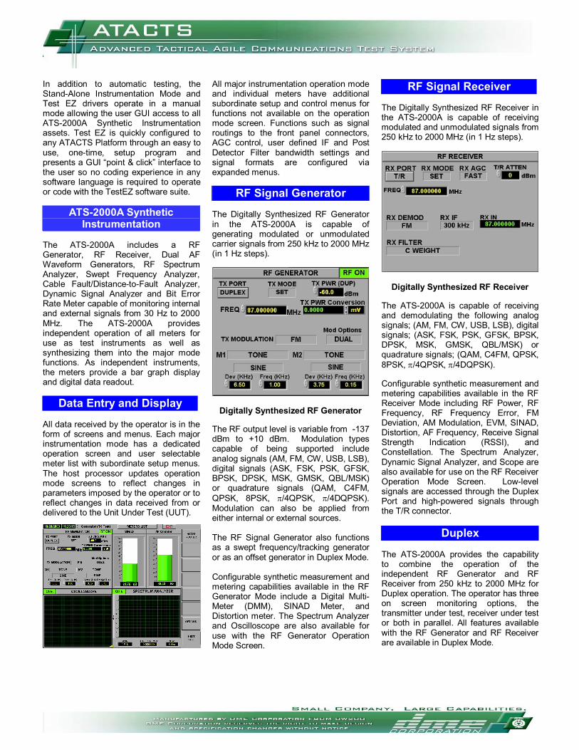
RF Signal Generator The Digitally Synthesized RF Generator in the ATS-2000A is capable of generating modulated or unmodulated carrier signals from 250 kHz to 2000 MHz (in 1 Hz steps).
Digitally Synthesized RF Generator The RF output level is variable from -137 dBm to +10 dBm. Modulation types capable of being supported include analog signals (AM, FM, CW, USB, LSB), digital signals (ASK, FSK, PSK, GFSK, BPSK, DPSK, MSK, GMSK, QBL/MSK) or quadrature signals (QAM, C4FM, QPSK, 8PSK, π/4QPSK, π/4DQPSK). Modulation can also be applied from either internal or external sources. The RF Signal Generator also functions as a swept frequency/tracking generator or as an offset generator in Duplex Mode. Configurable synthetic measurement and metering capabilities available in the RF Generator Mode include a Digital Multi-Meter (DMM), SINAD Meter, and Distortion meter. The Spectrum Analyzer and Oscilloscope are also available for use with the RF Generator Operation Mode Screen.
RF Signal Receiver The Digitally Synthesized RF Receiver in the ATS-2000A is capable of receiving modulated and unmodulated signals from 250 kHz to 2000 MHz (in 1 Hz steps).
Digitally Synthesized RF Receiver The ATS-2000A is capable of receiving and demodulating the following analog signals; (AM, FM, CW, USB, LSB), digital signals; (ASK, FSK, PSK, GFSK, BPSK, DPSK, MSK, GMSK, QBL/MSK) or quadrature signals; (QAM, C4FM, QPSK, 8PSK, π/4QPSK, π/4DQPSK). Configurable synthetic measurement and metering capabilities available in the RF Receiver Mode including RF Power, RF Frequency, RF Frequency Error, FM Deviation, AM Modulation, EVM, SINAD, Distortion, AF Frequency, Receive Signal Strength Indication (RSSI), and Constellation. The Spectrum Analyzer, Dynamic Signal Analyzer, and Scope are also available for use on the RF Receiver Operation Mode Screen. Low-level signals are accessed through the Duplex Port and high-powered signals through the T/R connector.
Duplex The ATS-2000A provides the capability to combine the operation of the independent RF Generator and RF Receiver from 250 kHz to 2000 MHz for Duplex operation. The operator has three on screen monitoring options, the transmitter under test, receiver under test or both in parallel. All features available with the RF Generator and RF Receiver are available in Duplex Mode.
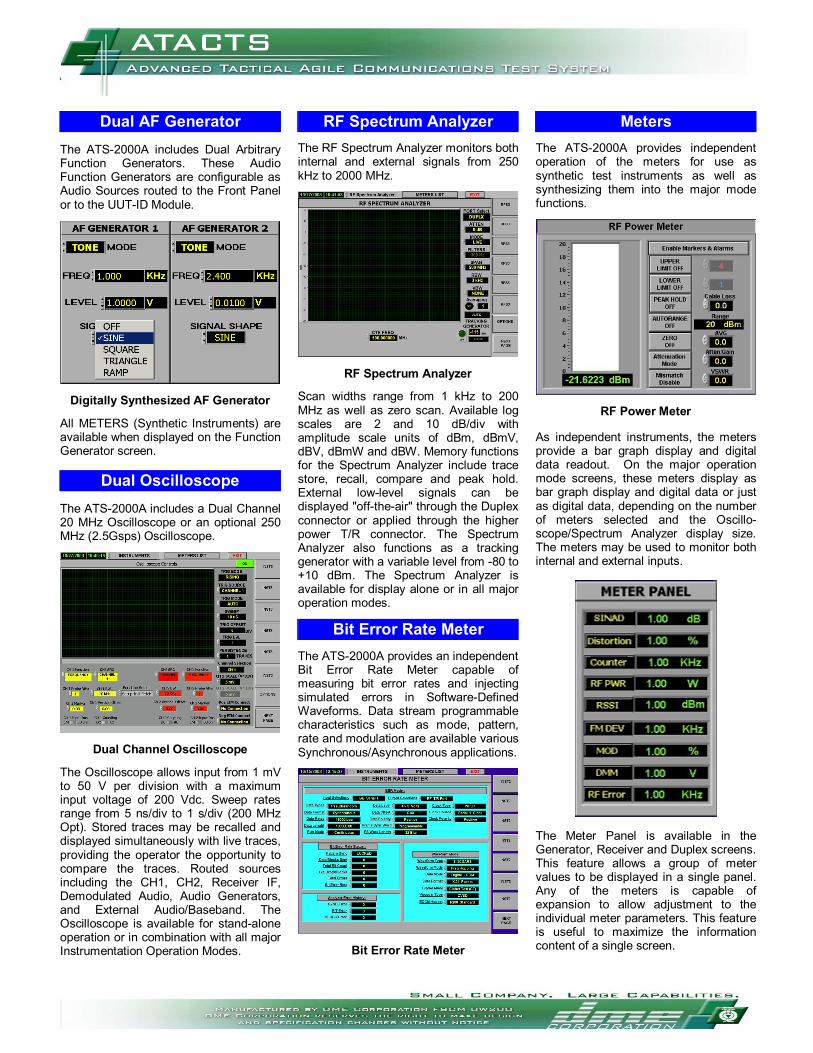
Dual AF Generator The ATS-2000A includes Dual Arbitrary Function Generators. These Audio Function Generators are configurable as Audio Sources routed to the Front Panel or to the UUT-ID Module.
Digitally Synthesized AF Generator All METERS (Synthetic Instruments) are available when displayed on the Function Generator screen.
Dual Oscilloscope The ATS-2000A includes a Dual Channel 20 MHz Oscilloscope or an optional 250 MHz (2.5Gsps) Oscilloscope.
Dual Channel Oscilloscope The Oscilloscope allows input from 1 mV to 50 V per division with a maximum input voltage of 200 Vdc. Sweep rates range from 5 ns/div to 1 s/div (200 MHz Opt). Stored traces may be recalled and displayed simultaneously with live traces, providing the operator the opportunity to compare the traces. Routed sources including the CH1, CH2, Receiver IF, Demodulated Audio, Audio Generators, and External Audio/Baseband. The Oscilloscope is available for stand-alone operation or in combination with all major Instrumentation Operation Modes.
RF Spectrum Analyzer The RF Spectrum Analyzer monitors both internal and external signals from 250 kHz to 2000 MHz.
RF Spectrum Analyzer Scan widths range from 1 kHz to 200 MHz as well as zero scan. Available log scales are 2 and 10 dB/div with amplitude scale units of dBm, dBmV, dBV, dBmW and dBW. Memory functions for the Spectrum Analyzer include trace store, recall, compare and peak hold. External low-level signals can be displayed "off-the-air" through the Duplex connector or applied through the higher power T/R connector. The Spectrum Analyzer also functions as a tracking generator with a variable level from -80 to +10 dBm. The Spectrum Analyzer is available for display alone or in all major operation modes.
Bit Error Rate Meter The ATS-2000A provides an independent Bit Error Rate Meter capable of measuring bit error rates and injecting simulated errors in Software-Defined Waveforms. Data stream programmable characteristics such as mode, pattern, rate and modulation are available various Synchronous/Asynchronous applications.
Bit Error Rate Meter
Meters The ATS-2000A provides independent operation of the meters for use as synthetic test instruments as well as synthesizing them into the major mode functions.
RF Power Meter As independent instruments, the meters provide a bar graph display and digital data readout. On the major operation mode screens, these meters display as bar graph display and digital data or just as digital data, depending on the number of meters selected and the Oscillo-scope/Spectrum Analyzer display size. The meters may be used to monitor both internal and external inputs.
The Meter Panel is available in the Generator, Receiver and Duplex screens. This feature allows a group of meter values to be displayed in a single panel. Any of the meters is capable of expansion to allow adjustment to the individual meter parameters. This feature is useful to maximize the information content of a single screen.
ATS-2000A Specifications
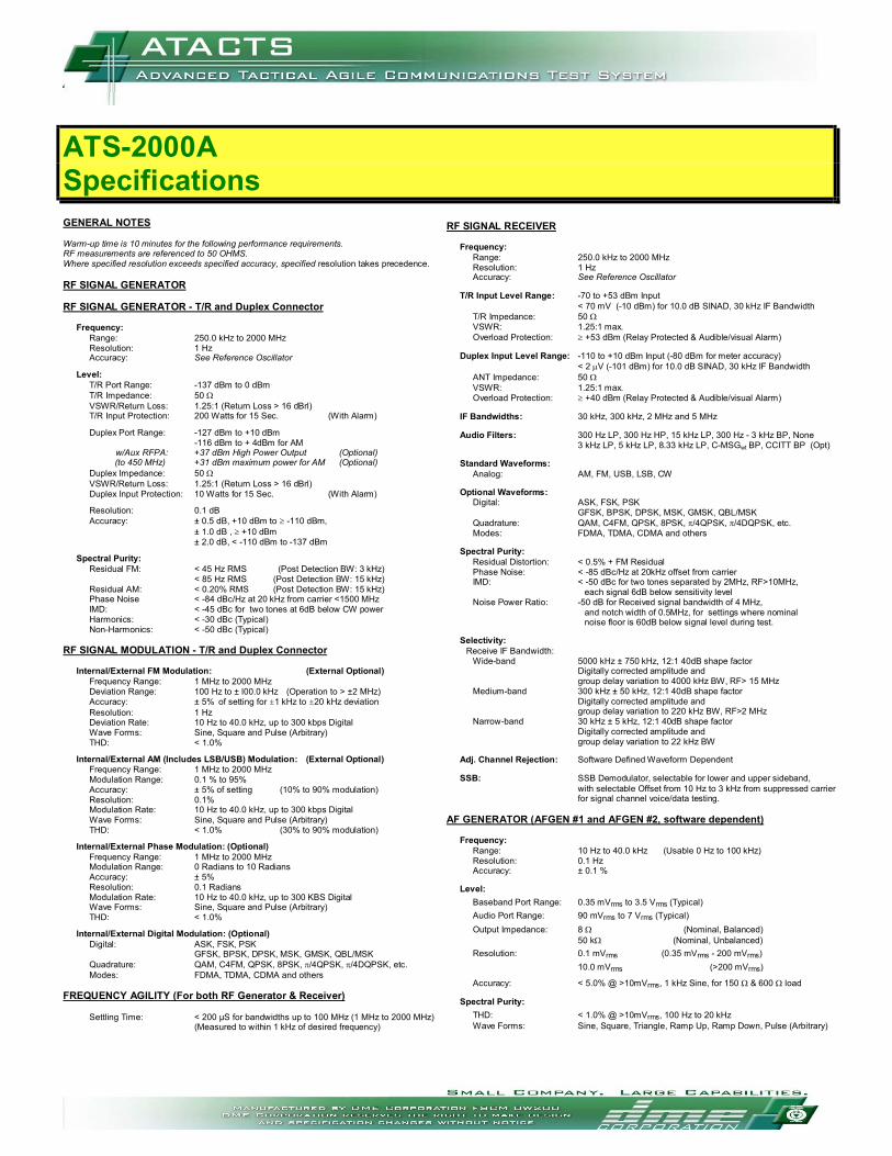
GENERAL NOTES Warm-up time is 10 minutes for the following performance requirements. RF measurements are referenced to 50 OHMS. Where specified resolution exceeds specified accuracy, specified resolution takes precedence. RF SIGNAL GENERATOR RF SIGNAL GENERATOR - T/R and Duplex Connector
Frequency: Range: 250.0 kHz to 2000 MHz Resolution: 1 Hz Accuracy: See Reference Oscillator
Level: T/R Port Range: -137 dBm to 0 dBm T/R Impedance: 50 Ω VSWR/Return Loss: 1.25:1 (Return Loss > 16 dBrl) T/R Input Protection: 200 Watts for 15 Sec. (With Alarm) Duplex Port Range: -127 dBm to +10 dBm -116 dBm to + 4dBm for AM w/Aux RFPA: +37 dBm High Power Output (Optional) (to 450 MHz) +31 dBm maximum power for AM (Optional) Duplex Impedance: 50 Ω VSWR/Return Loss: 1.25:1 (Return Loss > 16 dBrl) Duplex Input Protection: 10 Watts for 15 Sec. (With Alarm) Resolution: 0.1 dB Accuracy: ± 0.5 dB, +10 dBm to ≥ -110 dBm, ± 1.0 dB , ≥ +10 dBm ± 2.0 dB, < -110 dBm to -137 dBm
Spectral Purity: Residual FM: < 45 Hz RMS (Post Detection BW: 3 kHz) < 85 Hz RMS (Post Detection BW: 15 kHz) Residual AM: < 0.20% RMS (Post Detection BW: 15 kHz) Phase Noise < -84 dBc/Hz at 20 kHz from carrier <1500 MHz IMD: < -45 dBc for two tones at 6dB below CW power Harmonics: < -30 dBc (Typical) Non-Harmonics: < -50 dBc (Typical)
RF SIGNAL MODULATION - T/R and Duplex Connector
Internal/External FM Modulation: (External Optional) Frequency Range: 1 MHz to 2000 MHz Deviation Range: 100 Hz to ± l00.0 kHz (Operation to > ±2 MHz) Accuracy: ± 5% of setting for ±1 kHz to ±20 kHz deviation Resolution: 1 Hz Deviation Rate: 10 Hz to 40.0 kHz, up to 300 kbps Digital Wave Forms: Sine, Square and Pulse (Arbitrary) THD: < 1.0%
Internal/External AM (Includes LSB/USB) Modulation: (External Optional)
Frequency Range: 1 MHz to 2000 MHz Modulation Range: 0.1 % to 95% Accuracy: ± 5% of setting (10% to 90% modulation) Resolution: 0.1% Modulation Rate: 10 Hz to 40.0 kHz, up to 300 kbps Digital Wave Forms: Sine, Square and Pulse (Arbitrary) THD: < 1.0% (30% to 90% modulation)
Internal/External Phase Modulation: (Optional)
Frequency Range: 1 MHz to 2000 MHz Modulation Range: 0 Radians to 10 Radians Accuracy: ± 5% Resolution: 0.1 Radians Modulation Rate: 10 Hz to 40.0 kHz, up to 300 KBS Digital Wave Forms: Sine, Square and Pulse (Arbitrary) THD: < 1.0%
Internal/External Digital Modulation: (Optional)
Digital: ASK, FSK, PSK GFSK, BPSK, DPSK, MSK, GMSK, QBL/MSK Quadrature: QAM, C4FM, QPSK, 8PSK, π/4QPSK, π/4DQPSK, etc. Modes: FDMA, TDMA, CDMA and others
FREQUENCY AGILITY (For both RF Generator & Receiver)
Settling Time: < 200 µS for bandwidths up to 100 MHz (1 MHz to 2000 MHz) (Measured to within 1 kHz of desired frequency)
RF SIGNAL RECEIVER
Frequency: Range: 250.0 kHz to 2000 MHz
Resolution: 1 Hz Accuracy: See Reference Oscillator
T/R Input Level Range: -70 to +53 dBm Input < 70 mV (-10 dBm) for 10.0 dB SINAD, 30 kHz IF Bandwidth T/R Impedance: 50 Ω VSWR: 1.25:1 max. Overload Protection: ≥ +53 dBm (Relay Protected & Audible/visual Alarm) Duplex Input Level Range: -110 to +10 dBm Input (-80 dBm for meter accuracy) < 2 µV (-101 dBm) for 10.0 dB SINAD, 30 kHz IF Bandwidth ANT Impedance: 50 Ω VSWR: 1.25:1 max. Overload Protection: ≥ +40 dBm (Relay Protected & Audible/visual Alarm) IF Bandwidths: 30 kHz, 300 kHz, 2 MHz and 5 MHz Audio Filters: 300 Hz LP, 300 Hz HP, 15 kHz LP, 300 Hz - 3 kHz BP, None 3 kHz LP, 5 kHz LP, 8.33 kHz LP, C-MSGwt BP, CCITT BP (Opt)
Standard Waveforms: Analog: AM, FM, USB, LSB, CW
Optional Waveforms:
Digital: ASK, FSK, PSK GFSK, BPSK, DPSK, MSK, GMSK, QBL/MSK Quadrature: QAM, C4FM, QPSK, 8PSK, π/4QPSK, π/4DQPSK, etc.
Modes: FDMA, TDMA, CDMA and others
Spectral Purity: Residual Distortion: < 0.5% + FM Residual Phase Noise: < -85 dBc/Hz at 20kHz offset from carrier IMD: < -50 dBc for two tones separated by 2MHz, RF>10MHz, each signal 6dB below sensitivity level Noise Power Ratio: -50 dB for Received signal bandwidth of 4 MHz,
and notch width of 0.5MHz, for settings where nominal noise floor is 60dB below signal level during test. Selectivity: Receive IF Bandwidth: Wide-band 5000 kHz ± 750 kHz, 12:1 40dB shape factor Digitally corrected amplitude and group delay variation to 4000 kHz BW, RF> 15 MHz Medium-band 300 kHz ± 50 kHz, 12:1 40dB shape factor Digitally corrected amplitude and group delay variation to 220 kHz BW, RF>2 MHz Narrow-band 30 kHz ± 5 kHz, 12:1 40dB shape factor Digitally corrected amplitude and group delay variation to 22 kHz BW Adj. Channel Rejection: Software Defined Waveform Dependent
SSB: SSB Demodulator, selectable for lower and upper sideband, with selectable Offset from 10 Hz to 3 kHz from suppressed carrier
for signal channel voice/data testing. AF GENERATOR (AFGEN #1 and AFGEN #2, software dependent)
Frequency: Range: 10 Hz to 40.0 kHz (Usable 0 Hz to 100 kHz) Resolution: 0.1 Hz Accuracy: ± 0.1 %
Level:
Baseband Port Range: 0.35 mVrms to 3.5 Vrms (Typical) Audio Port Range: 90 mVrms to 7 Vrms (Typical) Output Impedance: 8 Ω (Nominal, Balanced) 50 kΩ (Nominal, Unbalanced)
Resolution: 0.1 mVrms (0.35 mVrms - 200 mVrms) 10.0 mVrms (>200 mVrms)
Accuracy: < 5.0% @ >10mVrms, 1 kHz Sine, for 150 Ω & 600 Ω load Spectral Purity:
THD: < 1.0% @ >10mVrms, 100 Hz to 20 kHz Wave Forms: Sine, Square, Triangle, Ramp Up, Ramp Down, Pulse (Arbitrary)
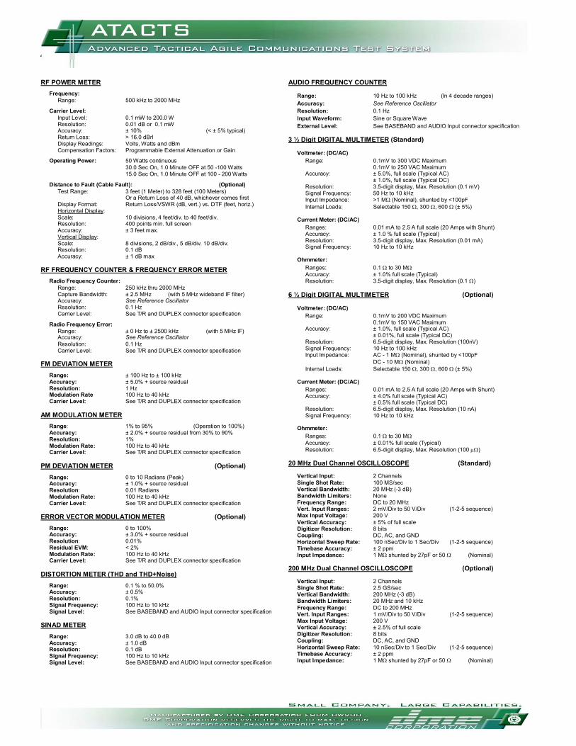
RF POWER METER
Frequency: Range: 500 kHz to 2000 MHz
Carrier Level:
Input Level: 0.1 mW to 200.0 W Resolution: 0.01 dB or 0.1 mW Accuracy: ± 10% (< ± 5% typical) Return Loss: > 16.0 dBrl Display Readings: Volts, Watts and dBm Compensation Factors: Programmable External Attenuation or Gain
Operating Power: 50 Watts continuous 30.0 Sec On, 1.0 Minute OFF at 50 -100 Watts 15.0 Sec On, 1.0 Minute OFF at 100 - 200 Watts Distance to Fault (Cable Fault): (Optional) Test Range: 3 feet (1 Meter) to 328 feet (100 Meters)
Or a Return Loss of 40 dB, whichever comes first Display Format: Return Loss/VSWR (dB, vert.) vs. DTF (feet, horiz.) Horizontal Display: Scale: 10 divisions, 4 feet/div. to 40 feet/div. Resolution: 400 points min. full screen Accuracy: ± 3 feet max. Vertical Display: Scale: 8 divisions, 2 dB/div., 5 dB/div. 10 dB/div. Resolution: 0.1 dB Accuracy: ± 1 dB max RF FREQUENCY COUNTER & FREQUENCY ERROR METER
Radio Frequency Counter: Range: 250 kHz thru 2000 MHz Capture Bandwidth: ± 2.5 MHz (with 5 MHz wideband IF filter) Accuracy: See Reference Oscillator Resolution: 0.1 Hz Carrier Level: See T/R and DUPLEX connector specification
Radio Frequency Error: Range: ± 0 Hz to ± 2500 kHz (with 5 MHz IF) Accuracy: See Reference Oscillator Resolution: 0.1 Hz
Carrier Level: See T/R and DUPLEX connector specification FM DEVIATION METER
Range: ± 100 Hz to ± 100 kHz Accuracy: ± 5.0% + source residual Resolution: 1 Hz Modulation Rate 100 Hz to 40 kHz Carrier Level: See T/R and DUPLEX connector specification
AM MODULATION METER
Range: 1% to 95% (Operation to 100%) Accuracy: ± 2.0% + source residual from 30% to 90% Resolution: 1% Modulation Rate: 100 Hz to 40 kHz Carrier Level: See T/R and DUPLEX connector specification
PM DEVIATION METER (Optional)
Range: 0 to 10 Radians (Peak) Accuracy: ± 1.0% + source residual Resolution: 0.01 Radians Modulation Rate: 100 Hz to 40 kHz Carrier Level: See T/R and DUPLEX connector specification
ERROR VECTOR MODULATION METER (Optional)
Range: 0 to 100% Accuracy: ± 3.0% + source residual Resolution: 0.01% Residual EVM: < 2% Modulation Rate: 100 Hz to 40 kHz Carrier Level: See T/R and DUPLEX connector specification
DISTORTION METER (THD and THD+Noise)
Range: 0.1 % to 50.0% Accuracy: ± 0.5% Resolution: 0.1% Signal Frequency: 100 Hz to 10 kHz Signal Level: See BASEBAND and AUDIO Input connector specification
SINAD METER
Range: 3.0 dB to 40.0 dB Accuracy: ± 1.0 dB Resolution: 0.1 dB Signal Frequency: 100 Hz to 10 kHz Signal Level: See BASEBAND and AUDIO Input connector specification
AUDIO FREQUENCY COUNTER
Range: 10 Hz to 100 kHz (In 4 decade ranges) Accuracy: See Reference Oscillator Resolution: 0.1 Hz Input Waveform: Sine or Square Wave External Level: See BASEBAND and AUDIO Input connector specification
3 ½ Digit DIGITAL MULTIMETER (Standard)
Voltmeter: (DC/AC) Range: 0.1mV to 300 VDC Maximum 0.1mV to 250 VAC Maximum Accuracy: ± 5.0%, full scale (Typical AC) ± 1.0%, full scale (Typical DC) Resolution: 3.5-digit display, Max. Resolution (0.1 mV) Signal Frequency: 50 Hz to 10 kHz Input Impedance: >1 MΩ (Nominal), shunted by <100pF Internal Loads: Selectable 150 Ω, 300 Ω, 600 Ω (± 5%)
Current Meter: (DC/AC) Ranges: 0.01 mA to 2.5 A full scale (20 Amps with Shunt) Accuracy: ± 1.0 % full scale (Typical)
Resolution: 3.5-digit display, Max. Resolution (0.01 mA) Signal Frequency: 10 Hz to 10 kHz
Ohmmeter:
Ranges: 0.1 Ω to 30 MΩ Accuracy: ± 1.0% full scale (Typical) Resolution: 3.5-digit display, Max. Resolution (0.1 Ω)
6 ½ Digit DIGITAL MULTIMETER (Optional)
Voltmeter: (DC/AC) Range: 0.1mV to 200 VDC Maximum 0.1mV to 150 VAC Maximum Accuracy: ± 1.0%, full scale (Typical AC) ± 0.01%, full scale (Typical DC) Resolution: 6.5-digit display, Max. Resolution (100nV) Signal Frequency: 10 Hz to 100 kHz Input Impedance: AC - 1 MΩ (Nominal), shunted by <100pF DC - 10 MΩ (Nominal) Internal Loads: Selectable 150 Ω, 300 Ω, 600 Ω (± 5%)
Current Meter: (DC/AC) Ranges: 0.01 mA to 2.5 A full scale (20 Amps with Shunt) Accuracy: ± 4.0% full scale (Typical AC) ± 0.5% full scale (Typical DC) Resolution: 6.5-digit display, Max. Resolution (10 nA)
Signal Frequency: 10 Hz to 10 kHz Ohmmeter:
Ranges: 0.1 Ω to 30 MΩ Accuracy: ± 0.01% full scale (Typical) Resolution: 6.5-digit display, Max. Resolution (100 µΩ)
20 MHz Dual Channel OSCILLOSCOPE (Standard)
Vertical Input: 2 Channels Single Shot Rate: 100 MS/sec Vertical Bandwidth: 20 MHz (-3 dB) Bandwidth Limiters: None Frequency Range: DC to 20 MHz Vert. Input Ranges: 2 mV/Div to 50 V/Div (1-2-5 sequence) Max Input Voltage: 200 V Vertical Accuracy: ± 5% of full scale Digitizer Resolution: 8 bits Coupling: DC, AC, and GND Horizontal Sweep Rate: 100 nSec/Div to 1 Sec/Div (1-2-5 sequence) Timebase Accuracy: ± 2 ppm Input Impedance: 1 MΩ shunted by 27pF or 50 Ω (Nominal)
200 MHz Dual Channel OSCILLOSCOPE (Optional)
Vertical Input: 2 Channels Single Shot Rate: 2.5 GS/sec Vertical Bandwidth: 200 MHz (-3 dB) Bandwidth Limiters: 20 MHz and 10 kHz Frequency Range: DC to 200 MHz Vert. Input Ranges: 1 mV/Div to 50 V/Div (1-2-5 sequence) Max Input Voltage: 200 V Vertical Accuracy: ± 2.5% of full scale Digitizer Resolution: 8 bits Coupling: DC, AC, and GND Horizontal Sweep Rate: 10 nSec/Div to 1 Sec/Div (1-2-5 sequence) Timebase Accuracy: ± 2 ppm Input Impedance: 1 MΩ shunted by 27pF or 50 Ω (Nominal)
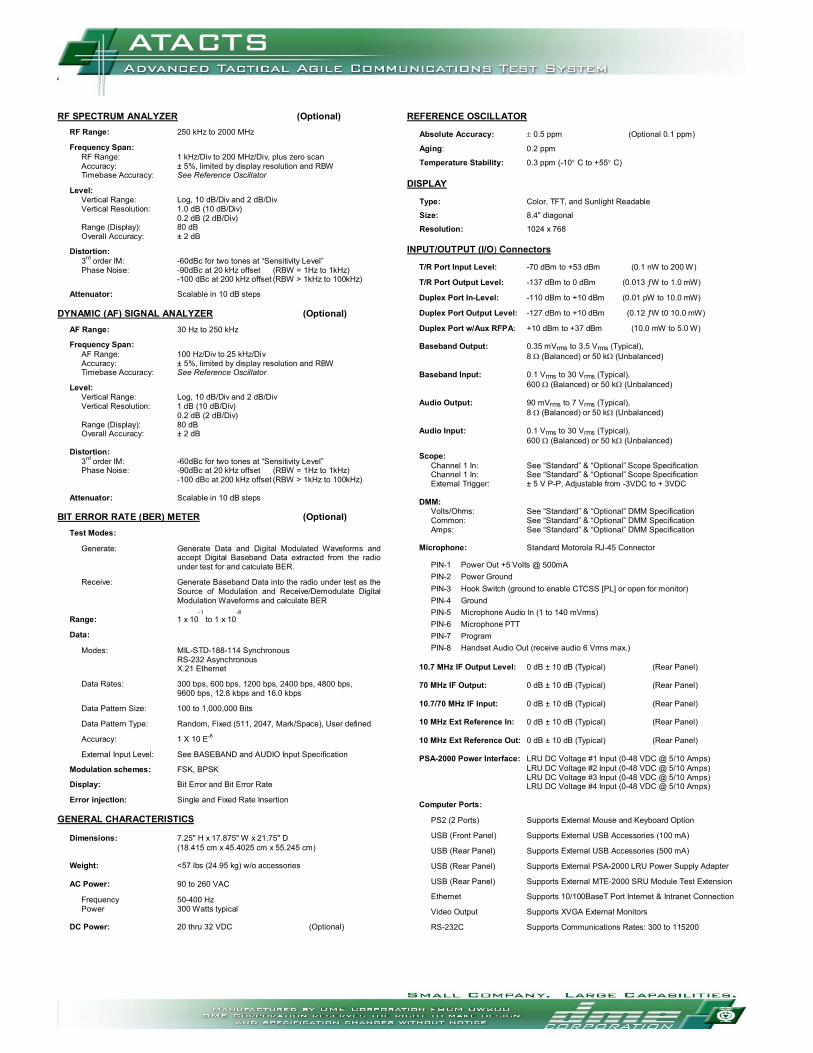
RF SPECTRUM ANALYZER (Optional)
RF Range: 250 kHz to 2000 MHz Frequency Span:
RF Range: 1 kHz/Div to 200 MHz/Div, plus zero scan Accuracy: ± 5%, limited by display resolution and RBW Timebase Accuracy: See Reference Oscillator
Level:
Vertical Range: Log, 10 dB/Div and 2 dB/Div Vertical Resolution: 1.0 dB (10 dB/Div) 0.2 dB (2 dB/Div) Range (Display): 80 dB Overall Accuracy: ± 2 dB
Distortion: 3rd order IM: -60dBc for two tones at “Sensitivity Level”
Phase Noise: -90dBc at 20 kHz offset (RBW = 1Hz to 1kHz) -100 dBc at 200 kHz offset (RBW > 1kHz to 100kHz)
Attenuator: Scalable in 10 dB steps
DYNAMIC (AF) SIGNAL ANALYZER (Optional)
AF Range: 30 Hz to 250 kHz Frequency Span:
AF Range: 100 Hz/Div to 25 kHz/Div Accuracy: ± 5%, limited by display resolution and RBW Timebase Accuracy: See Reference Oscillator
Level:
Vertical Range: Log, 10 dB/Div and 2 dB/Div Vertical Resolution: 1 dB (10 dB/Div) 0.2 dB (2 dB/Div) Range (Display): 80 dB Overall Accuracy: ± 2 dB
Distortion: 3rd order IM: -60dBc for two tones at “Sensitivity Level”
Phase Noise: -90dBc at 20 kHz offset (RBW = 1Hz to 1kHz) -100 dBc at 200 kHz offset (RBW > 1kHz to 100kHz) Attenuator: Scalable in 10 dB steps
BIT ERROR RATE (BER) METER (Optional) Test Modes:
Generate: Generate Data and Digital Modulated Waveforms and accept Digital Baseband Data extracted from the radio under test for and calculate BER.
Receive: Generate Baseband Data into the radio under test as the
Source of Modulation and Receive/Demodulate Digital Modulation Waveforms and calculate BER
Range: 1 x 10⁻¹
to 1 x 10⁻⁸
Data: Modes: MIL-STD-188-114 Synchronous RS-232 Asynchronous X.21 Ethernet Data Rates: 300 bps, 600 bps, 1200 bps, 2400 bps, 4800 bps, 9600 bps, 12.8 kbps and 16.0 kbps Data Pattern Size: 100 to 1,000,000 Bits Data Pattern Type: Random, Fixed (511, 2047, Mark/Space), User defined Accuracy: 1 X 10 E-8
External Input Level: See BASEBAND and AUDIO Input Specification Modulation schemes: FSK, BPSK Display: Bit Error and Bit Error Rate Error injection: Single and Fixed Rate Insertion GENERAL CHARACTERISTICS Dimensions: 7.25" H x 17.875" W x 21.75" D (18.415 cm x 45.4025 cm x 55.245 cm) Weight: <57 lbs (24.95 kg) w/o accessories AC Power: 90 to 260 VAC Frequency 50-400 Hz Power 300 Watts typical DC Power: 20 thru 32 VDC (Optional)
REFERENCE OSCILLATOR
Absolute Accuracy: ± 0.5 ppm (Optional 0.1 ppm)
Aging: 0.2 ppm
Temperature Stability: 0.3 ppm (-10° C to +55° C)
DISPLAY
Type: Color, TFT, and Sunlight Readable
Size: 8.4" diagonal
Resolution: 1024 x 768
INPUT/OUTPUT (I/O) Connectors
T/R Port Input Level: -70 dBm to +53 dBm (0.1 nW to 200 W)
T/R Port Output Level: -137 dBm to 0 dBm (0.013 ƒW to 1.0 mW) Duplex Port In-Level: -110 dBm to +10 dBm (0.01 pW to 10.0 mW) Duplex Port Output Level: -127 dBm to +10 dBm (0.12 ƒW t0 10.0 mW) Duplex Port w/Aux RFPA: +10 dBm to +37 dBm (10.0 mW to 5.0 W)
Baseband Output: 0.35 mVrms to 3.5 Vrms (Typical), 8 Ω (Balanced) or 50 kΩ (Unbalanced)
Baseband Input: 0.1 Vrms to 30 Vrms (Typical), 600 Ω (Balanced) or 50 kΩ (Unbalanced)
Audio Output: 90 mVrms to 7 Vrms (Typical), 8 Ω (Balanced) or 50 kΩ (Unbalanced)
Audio Input: 0.1 Vrms to 30 Vrms (Typical), 600 Ω (Balanced) or 50 kΩ (Unbalanced) Scope:
Channel 1 In: See “Standard” & “Optional” Scope Specification Channel 1 In: See “Standard” & “Optional” Scope Specification External Trigger: ± 5 V P-P, Adjustable from -3VDC to + 3VDC
DMM:
Volts/Ohms: See “Standard” & “Optional” DMM Specification Common: See “Standard” & “Optional” DMM Specification Amps: See “Standard” & “Optional” DMM Specification
Microphone: Standard Motorola RJ-45 Connector
PIN-1 Power Out +5 Volts @ 500mA PIN-2 Power Ground PIN-3 Hook Switch (ground to enable CTCSS [PL] or open for monitor) PIN-4 Ground PIN-5 Microphone Audio In (1 to 140 mVrms) PIN-6 Microphone PTT PIN-7 Program PIN-8 Handset Audio Out (receive audio 6 Vrms max.)
10.7 MHz IF Output Level: 0 dB ± 10 dB (Typical) (Rear Panel) 70 MHz IF Output: 0 dB ± 10 dB (Typical) (Rear Panel) 10.7/70 MHz IF Input: 0 dB ± 10 dB (Typical) (Rear Panel) 10 MHz Ext Reference In: 0 dB ± 10 dB (Typical) (Rear Panel) 10 MHz Ext Reference Out: 0 dB ± 10 dB (Typical) (Rear Panel) PSA-2000 Power Interface: LRU DC Voltage #1 Input (0-48 VDC @ 5/10 Amps) LRU DC Voltage #2 Input (0-48 VDC @ 5/10 Amps) LRU DC Voltage #3 Input (0-48 VDC @ 5/10 Amps) LRU DC Voltage #4 Input (0-48 VDC @ 5/10 Amps) Computer Ports:
PS2 (2 Ports) Supports External Mouse and Keyboard Option USB (Front Panel) Supports External USB Accessories (100 mA) USB (Rear Panel) Supports External USB Accessories (500 mA) USB (Rear Panel) Supports External PSA-2000 LRU Power Supply Adapter USB (Rear Panel) Supports External MTE-2000 SRU Module Test Extension Ethernet Supports 10/100BaseT Port Internet & Intranet Connection Video Output Supports XVGA External Monitors RS-232C Supports Communications Rates: 300 to 115200
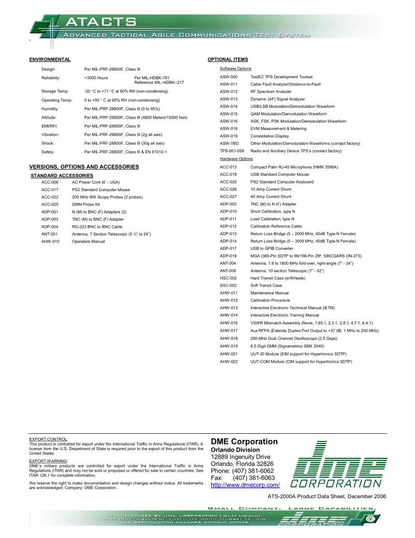
ENVIRONMENTAL Design: Per MIL-PRF-28800F, Class III Reliability: >3000 Hours Per MIL-HDBK-781 Reference MIL–HDBK–217 Storage Temp: -20 °C to +71 °C at 80% RH (non-condensing) Operating Temp: 0 to +50 ° C at 95% RH (non-condensing) Humidity: Per MIL-PRF-28800F, Class III (0 to 95%) Altitude: Per MIL-PRF-28800F, Class III (4600 Meters/15000 feet) EMI/RFI: Per MIL-PRF-28800F, Class III Vibration: Per MIL-PRF-28800F, Class III (2g all axis) Shock: Per MIL-PRF-28800F, Class III (30g all axis) Safety: Per MIL-PRF-28800F, Class III & EN 61010-1 VERSIONS, OPTIONS AND ACCESSORIES
STANDARD ACCESSORIES ACC-006 AC Power Cord (6’ - USA)
ACC-017 PS2 Standard Computer Mouse
ACC-022 200 MHz BW Scope Probes (2 probes)
ACC-025 DMM Probe Kit
ADP-001 N (M) to BNC (F) Adapters (2)
ADP-003 TNC (M) to BNC (F) Adapter
ADP-004 RG-223 BNC to BNC Cable
ANT-001 Antenna, 7 Section Telescopic (5 ¼” to 24”)
AHW-010 Operators Manual EXPORT CONTROL: This product is controlled for export under the International Traffic in Arms Regulations (ITAR). A license from the U.S. Department of State is required prior to the export of this product from the United States. EXPORT WARNING: DME’s military products are controlled for export under the International Traffic in Arms Regulations (ITAR) and may not be sold or proposed or offered for sale to certain countries. See ITAR 126.1 for complete information. We reserve the right to make documentation and design changes without notice. All trademarks are acknowledged. Company: DME Corporation.
OPTIONAL ITEMS
Software Options
ASW-000 TestEZ TPS Development Toolset
ASW-011 Cable Fault Analyzer/Distance-to-Fault
ASW-012 RF Spectrum Analyzer
ASW-013 Dynamic (AF) Signal Analyzer
ASW-014 USB/LSB Modulation/Demodulation Waveform
ASW-015 QAM Modulation/Demodulation Waveform
ASW-016 ASK, FSK, PSK Modulation/Demodulation Waveform
ASW-018 EVM Measurement & Metering
ASW-019 Constellation Display
ASW-TBD Other Modulation/Demodulation Waveforms (contact factory)
TPS-001-059 Radio and Ancillary Device TPS’s (contact factory)
Hardware Options
ACC-013 Compact Palm RJ-45 Microphone (HMN 3596A)
ACC-018 USB Standard Computer Mouse
ACC-020 PS2 Standard Computer Keyboard
ACC-026 10 Amp Current Shunt
ACC-027 40 Amp Current Shunt
ADP-002 TNC (M) to N (F) Adapter
ADP-010 Short Calibration, type N
ADP-011 Load Calibration, type N
ADP-012 Calibration Reference Cable
ADP-013 Return Loss Bridge (5 – 2000 MHz, 40dB Type-N Female)
ADP-014 Return Loss Bridge (5 – 3000 MHz, 40dB Type-N Female)
ADP-017 USB to GPIB Converter
ADP-019 MGA (360-Pin SDTP to 96/156-Pin ZIP, SINCGARS ON-373)
ANT-004 Antenna, 1.8 to 1800 MHz fold-over, right-angle (7” - 24”)
ANT-006 Antenna, 10 section Telescopic (7” - 52”)
HSC-002 Hard Transit Case (w/Wheels)
SSC-002 Soft Transit Case
AHW-011 Maintenance Manual
AHW-012 Calibration Procedure
AHW-013 Interactive Electronic Technical Manual (IETM)
AHW-014 Interactive Electronic Training Manual
AHW-016 VSWR Mismatch Assembly (None, 1.65:1, 2.3:1, 2.8:1, 4.7:1, 6.4:1)
AHW-017 Aux RFPA (Extends Duplex Port Output to +37 dB, 1 MHz to 250 MHz)
AHW-018 250 MHz Dual Channel Oscilloscope (2.5 Gsps)
AHW-019 6.5 Digit DMM (Signametrics SMX 2040)
AHW-021 UUT-ID Module (EIM support for Hypertronics SDTP)
AHW-022 UUT-COM Module (CIM support for Hypertronics SDTP)
DME Corporation Orlando Division 12889 Ingenuity Drive Orlando, Florida 32826 Phone: (407) 381-6062 Fax: (407) 381-6063 http://www.dmecorp.com/
ATS-2000A Product Data Sheet, December 2006