at&t ip flexible reach and ip toll free cisco call manager configuration guide issue 2 ... ·...
TRANSCRIPT

AT&T IP Flexible Reach Call Manager Configuration Guide
AT&T IP Flexible Reach And IP Toll Free
Cisco Call Manager Configuration Guide
Issue 2.13 6/5/2007
Page 1 of 38
AT&T IP Flexible Reach Call Manager Configuration Guide
TABLE OF CONTENTS
1 Introduction................................................................................................................. 3 2 Special Notes .............................................................................................................. 3 3 Overview..................................................................................................................... 4
3.1 Call Manager Site ............................................................................................... 4 3.2 TFTP and DHCP Configuration Guidelines ....................................................... 4
4 Configuration Guide ................................................................................................... 5 4.1 Call Manager Version......................................................................................... 6 4.2 Dual AT&T Border Element Connection ........................................................... 8
4.2.1 Gateway ...................................................................................................... 8 4.2.2 Route Group.............................................................................................. 11 4.2.3 Route List.................................................................................................. 13 4.2.4 Route Pattern............................................................................................. 14
4.3 Calling Party Number Translation Configuration............................................. 16 4.4 Incoming Call Routing on Telephone Number................................................. 18 4.5 Region - WAN .................................................................................................. 20 4.6 Region – Default ............................................................................................... 21 4.7 Device Pool – WAN ......................................................................................... 22 4.8 Device Pool – Default....................................................................................... 23 4.9 Media Resource Group ..................................................................................... 24 4.10 Media Resource Group List .............................................................................. 25 4.11 Conference Bridge ............................................................................................ 26 4.12 Transcoder......................................................................................................... 27 4.13 Phone Configuration ......................................................................................... 28 4.14 Service Parameters............................................................................................ 29
5 IP Toll Free Specific Information ............................................................................. 30 5.1 Call Flow with IP Call Center........................................................................... 30 5.2 Examples for Call Manager Configuration for IPCC ....................................... 32
5.2.1 CTI Route Points....................................................................................... 33 5.2.2 Incoming Call Routing for IP Toll Free.................................................... 34 5.2.3 JTAPI User Definitions............................................................................. 35
6 Appendix A: Router Version/Configuration for Transcoding.................................. 36 6.1 Router Version .................................................................................................. 36 6.2 Transcoding Configuration ............................................................................... 36
7 Appendix B: Firewall Rules...................................................................................... 37
Page 2 of 38
AT&T IP Flexible Reach Call Manager Configuration Guide
1 Introduction This document provides a configuration guide to assist Cisco Call Manager administrators in connecting to AT&T IP Flexible Reach Services and IP Toll Free.
2 Special Notes Emergency 911/E911 Services Limitations While AT&T IP Flexible Reach services support E911/911 calling capabilities in certain circumstances, there are significant limitations on how these capabilities are delivered. Please review the AT&T IP Flexible Reach Service Guide in detail to understand these limitations and restrictions. Fax Not Supported on G.729 Calls Customers using the AT&T IP Flexible Reach Service generally use the G.729 Codec for voice calls. When a customer makes a fax call rather than a voice call, IP Flexible Reach service detects this fax tone and converts the call to the G.711 ulaw Codec. This codec provides greater reliability than G.729 for fax calls. This change to G.711 however is not currently supported by Cisco on H.323 trunks. Unity Voice Mail Access Does Not Work From a TDM PBX Site Unity Voice Mail access from a TDM PBX with a SIP gateway in the AT&T managed router (i.e. with IP Long Distance or IP Flexible Reach Service) is not supported. Unity Voice Mail access works fine from a PSTN endpoint. Certain Unattended Transfers to the PSTN Result in No Ring Back Certain unattended transfers to PSTN endpoints do not return ring back prior to connect.
Page 3 of 38
AT&T IP Flexible Reach Call Manager Configuration Guide
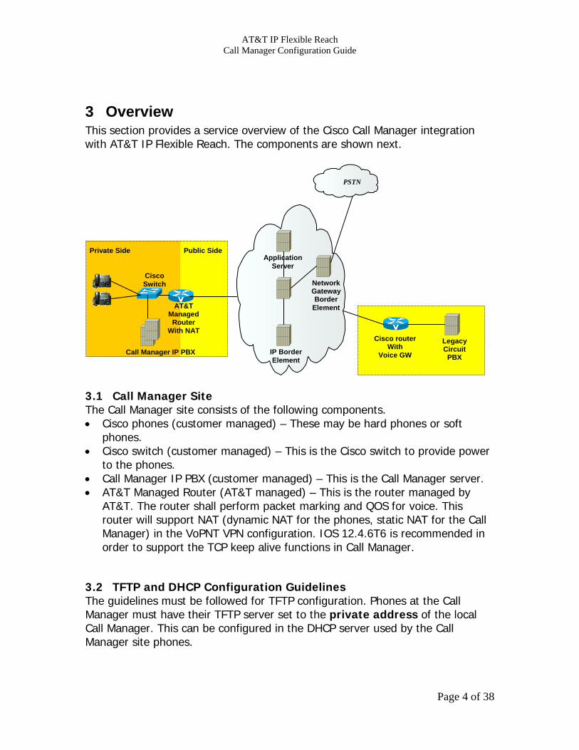
3 Overview This section provides a service overview of the Cisco Call Manager integration with AT&T IP Flexible Reach. The components are shown next.
3.1 Call Manager Site The Call Manager site consists of the following components. • Cisco phones (customer managed) – These may be hard phones or soft
phones. • Cisco switch (customer managed) – This is the Cisco switch to provide power
to the phones. • Call Manager IP PBX (customer managed) – This is the Call Manager server. • AT&T Managed Router (AT&T managed) – This is the router managed by
AT&T. The router shall perform packet marking and QOS for voice. This router will support NAT (dynamic NAT for the phones, static NAT for the Call Manager) in the VoPNT VPN configuration. IOS 12.4.6T6 is recommended in order to support the TCP keep alive functions in Call Manager.
3.2 TFTP and DHCP Configuration Guidelines The guidelines must be followed for TFTP configuration. Phones at the Call Manager must have their TFTP server set to the private address of the local Call Manager. This can be configured in the DHCP server used by the Call Manager site phones.
Call Manager IP PBX
Private Side
Legacy Circuit
PBX
Cisco router With
Voice GW
Public Side
Cisco Switch
AT&T Managed
Router With NAT
IP BorderElement
NetworkGatewayBorder
Element
ApplicationServer
PSTN
Page 4 of 38

AT&T IP Flexible Reach Call Manager Configuration Guide
4 Configuration Guide This configuration guide specifies the Call Manager screens that must be configured and updated to support the AT&T IP Flexible Reach.
Page 5 of 38

AT&T IP Flexible Reach Call Manager Configuration Guide
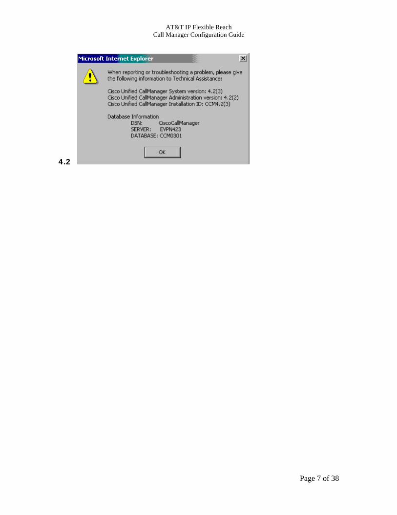
4.1 Call Manager Version For IP Flexible Reach, the Call Manager must be running one of the following releases: 4.1.(3), 4.2.(1), or 4.2.(3). The most recent service release is adequate. (See section 5 for IP Toll Free requirements.) You can check the version of Call Manager from the about option on the help menu and then selecting details as shown next.
Page 6 of 38
AT&T IP Flexible Reach Call Manager Configuration Guide
4.2
Page 7 of 38

AT&T IP Flexible Reach Call Manager Configuration Guide
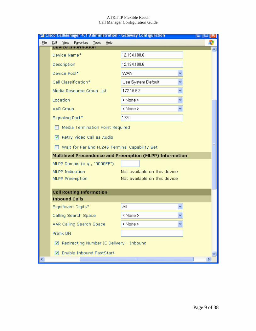
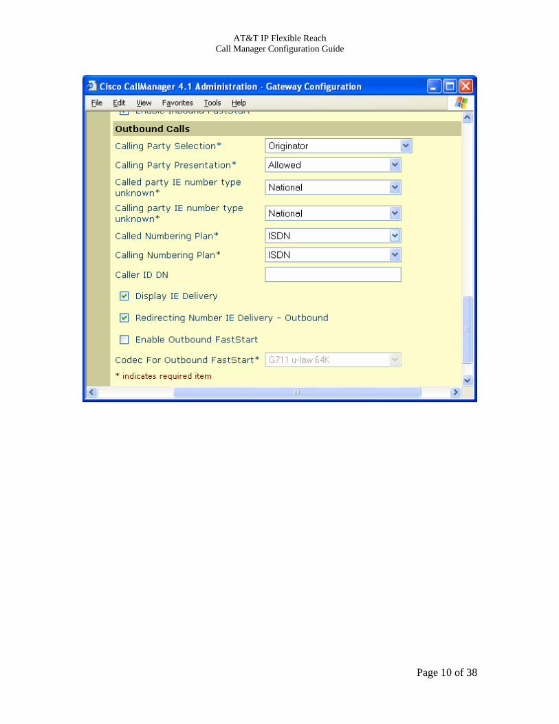
Dual AT&T Border Element Connection This section describes the procedure for connecting to dual AT&T Border Elements. 4.2.1 Gateway This screen specifies the parameters for connecting to each of the AT&T Border Elements. Two gateways must be configured (i.e. one for each border element). Note that only border element is shown. It is accessed from the Device menu. Key parameters are: Device Name: This is the IP address of the AT&T Border Element specified in this gateway screen. Two gateway screens are recommended (one for each AT&T Border Element). Sample IP addresses are shown in the screens. PLEASE CONTACT YOUR CUSTOMER CARE REPRESENTATIVE FOR THE AT&T IP BORDER ELEMENT IP ADDRESSES FOR YOUR SPECIFIC PBX. Device Pool: Device pool points to a region that specifies the codec and media resources (e.g. conference bridge, transcoder, etc) to be used. Significant Digits: Number of right most digits that will be extracted from the called number. For the virtual telephone number (VTN) feature, this field must be set to ALL. Wait for Far End H.245 Terminal Capability Set – This field must be unchecked. Enabled Inbound FastStart: This specifies that the Call Manager can accept the H.323 fast start element in the call setup messages. Calling Party Presentation – Must set to “Allowed”. Caller ID DN – Set this to the phone number prefix for this site. Call Manager will prepend this string to the extension when the calling number is generated. Calling Search Space – If the Call Manager phones are assigned to a calling search space, then the calling search space on the gateway form must be set to the same value.
Page 8 of 38
AT&T IP Flexible Reach Call Manager Configuration Guide
Page 9 of 38
AT&T IP Flexible Reach Call Manager Configuration Guide
Page 10 of 38

AT&T IP Flexible Reach Call Manager Configuration Guide
4.2.2 Route Group The route group specifies a set of alternate routes. If the connection to one AT&T Border element fails, Call Manager will attempt a connection to the other border element. It is accessed from the Route Plan menu. Key fields are: Route Group Name: This is name of the route group. Distribution Algorithm: Set this to top down. The first BE will be primary and the second will be backup. Selected Devices: These are the gateway devices previously configured.
Page 11 of 38

AT&T IP Flexible Reach Call Manager Configuration Guide
Page 12 of 38
AT&T IP Flexible Reach Call Manager Configuration Guide
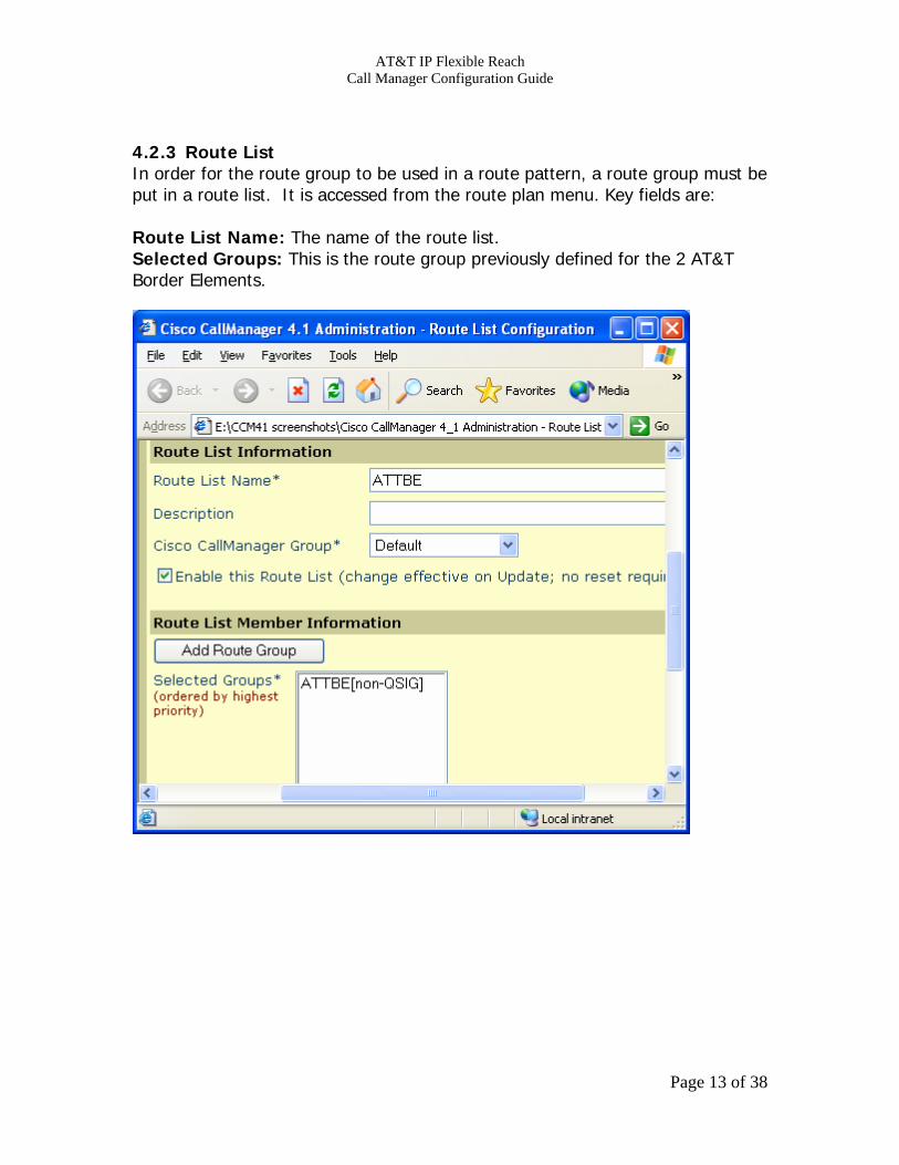
4.2.3 Route List In order for the route group to be used in a route pattern, a route group must be put in a route list. It is accessed from the route plan menu. Key fields are: Route List Name: The name of the route list. Selected Groups: This is the route group previously defined for the 2 AT&T Border Elements.
Page 13 of 38
AT&T IP Flexible Reach Call Manager Configuration Guide
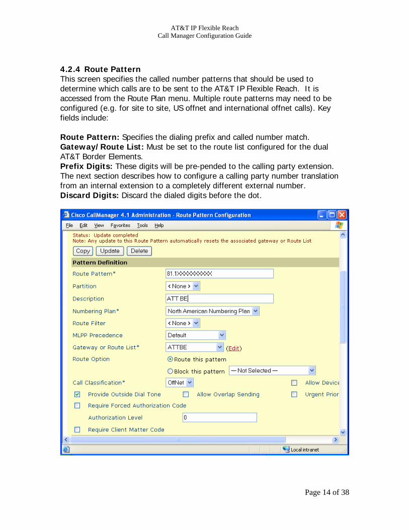
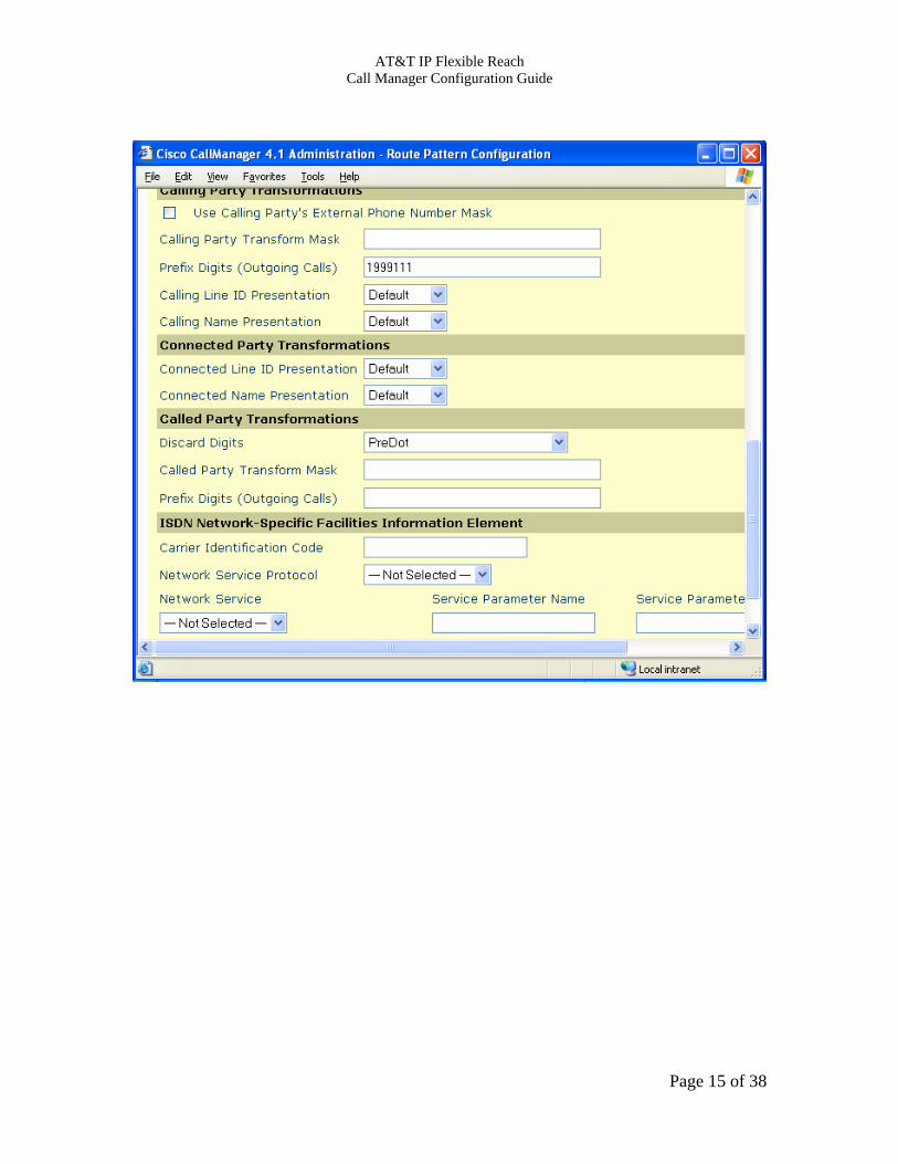
4.2.4 Route Pattern This screen specifies the called number patterns that should be used to determine which calls are to be sent to the AT&T IP Flexible Reach. It is accessed from the Route Plan menu. Multiple route patterns may need to be configured (e.g. for site to site, US offnet and international offnet calls). Key fields include: Route Pattern: Specifies the dialing prefix and called number match. Gateway/Route List: Must be set to the route list configured for the dual AT&T Border Elements. Prefix Digits: These digits will be pre-pended to the calling party extension. The next section describes how to configure a calling party number translation from an internal extension to a completely different external number. Discard Digits: Discard the dialed digits before the dot.
Page 14 of 38
AT&T IP Flexible Reach Call Manager Configuration Guide
Page 15 of 38

AT&T IP Flexible Reach Call Manager Configuration Guide
4.3 Calling Party Number Translation Configuration This section specifies how to configure a calling party number translation from an internal extension to a completely different external number. This configuration is required for the Virtual Telephone Number (VTN) feature. On the directory number screen for the internal extension, set the External Phone Number Mask to the desired external calling party number.
Page 16 of 38
AT&T IP Flexible Reach Call Manager Configuration Guide
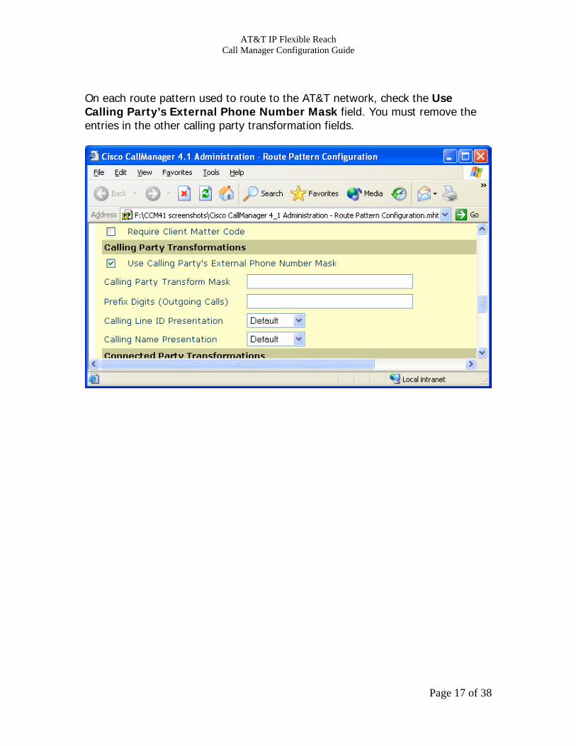
On each route pattern used to route to the AT&T network, check the Use Calling Party’s External Phone Number Mask field. You must remove the entries in the other calling party transformation fields.
Page 17 of 38
AT&T IP Flexible Reach Call Manager Configuration Guide
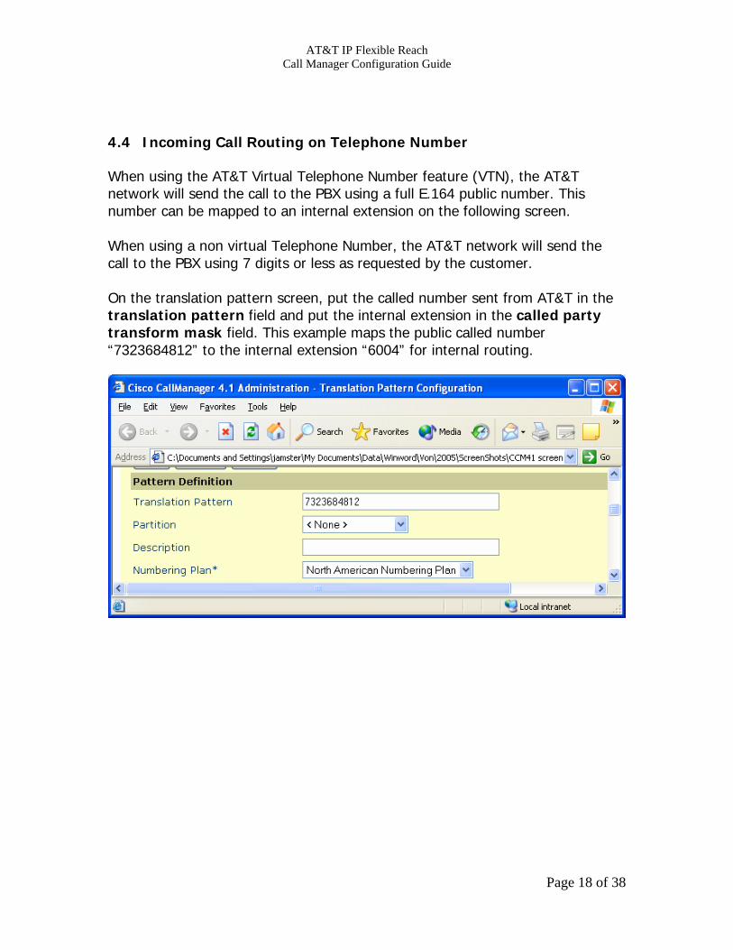
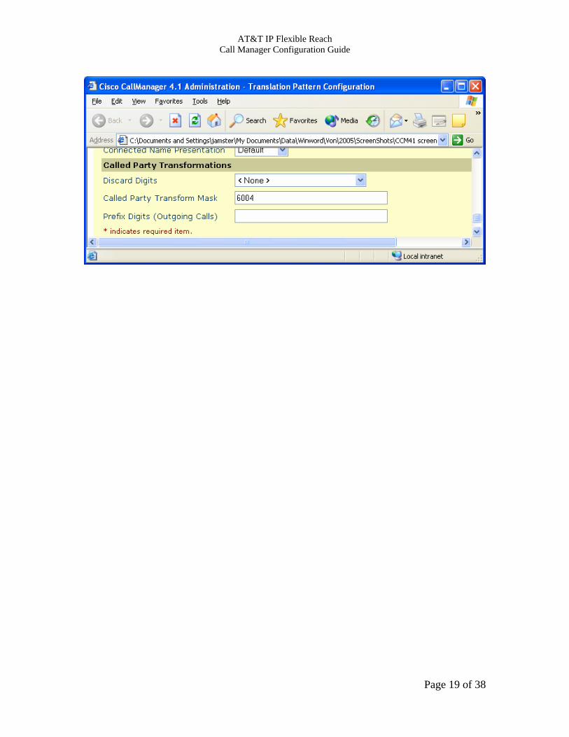
4.4 Incoming Call Routing on Telephone Number When using the AT&T Virtual Telephone Number feature (VTN), the AT&T network will send the call to the PBX using a full E.164 public number. This number can be mapped to an internal extension on the following screen. When using a non virtual Telephone Number, the AT&T network will send the call to the PBX using 7 digits or less as requested by the customer. On the translation pattern screen, put the called number sent from AT&T in the translation pattern field and put the internal extension in the called party transform mask field. This example maps the public called number “7323684812” to the internal extension “6004” for internal routing.
Page 18 of 38
AT&T IP Flexible Reach Call Manager Configuration Guide
Page 19 of 38

AT&T IP Flexible Reach Call Manager Configuration Guide
4.5 Region - WAN The region specifies the codec to be used for devices that point to this region. This particular region is used by devices associated with the AT&T Border Elements. This screen is accessed from the system menu. Key fields are: Default: Specifies that the G.729 codec to be used with the default region. WAN: Specifies that the G.729 codec to be used with other devices in this region.
Page 20 of 38
AT&T IP Flexible Reach Call Manager Configuration Guide
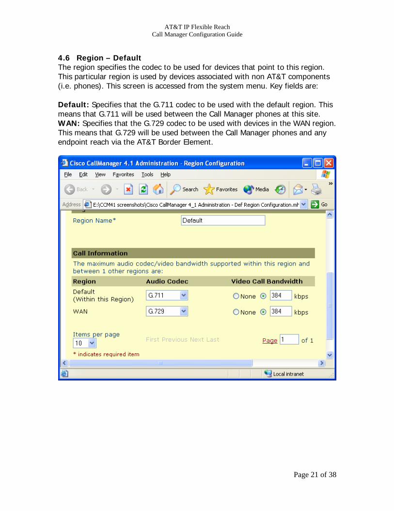
4.6 Region – Default The region specifies the codec to be used for devices that point to this region. This particular region is used by devices associated with non AT&T components (i.e. phones). This screen is accessed from the system menu. Key fields are: Default: Specifies that the G.711 codec to be used with the default region. This means that G.711 will be used between the Call Manager phones at this site. WAN: Specifies that the G.729 codec to be used with devices in the WAN region. This means that G.729 will be used between the Call Manager phones and any endpoint reach via the AT&T Border Element.
Page 21 of 38

AT&T IP Flexible Reach Call Manager Configuration Guide
4.7 Device Pool – WAN The device pool specifies parameters to be used by devices that point to this device pool. This particular device pool is used by devices associated with the AT&T Gatekeeper. This screen is accessed from the system menu. Key fields are: Region: The region specifies the codec to be used for this device pool. Media Resource Group List: This points to a media resource group that specifies media resources (i.e. conference bridges, transcoders, etc) to be used for this device pool.
Page 22 of 38
AT&T IP Flexible Reach Call Manager Configuration Guide
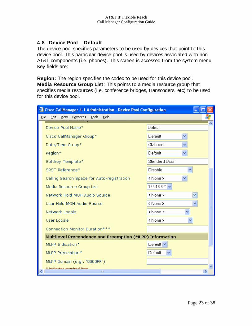
4.8 Device Pool – Default The device pool specifies parameters to be used by devices that point to this device pool. This particular device pool is used by devices associated with non AT&T components (i.e. phones). This screen is accessed from the system menu. Key fields are: Region: The region specifies the codec to be used for this device pool. Media Resource Group List: This points to a media resource group that specifies media resources (i.e. conference bridges, transcoders, etc) to be used for this device pool.
Page 23 of 38

AT&T IP Flexible Reach Call Manager Configuration Guide
4.9 Media Resource Group The media resource group specifies a grouping of media resources (i.e. conference bridge, transcoder, etc). This particular media resource group contains a conference bridge and a transcoder. This screen is accessed from the service/media resource menu. Key fields are: Selected Media Resources: Points to profiles for conference bridge (CFB) and transcoder (XCODE) resources to be used in this group.
Page 24 of 38
AT&T IP Flexible Reach Call Manager Configuration Guide
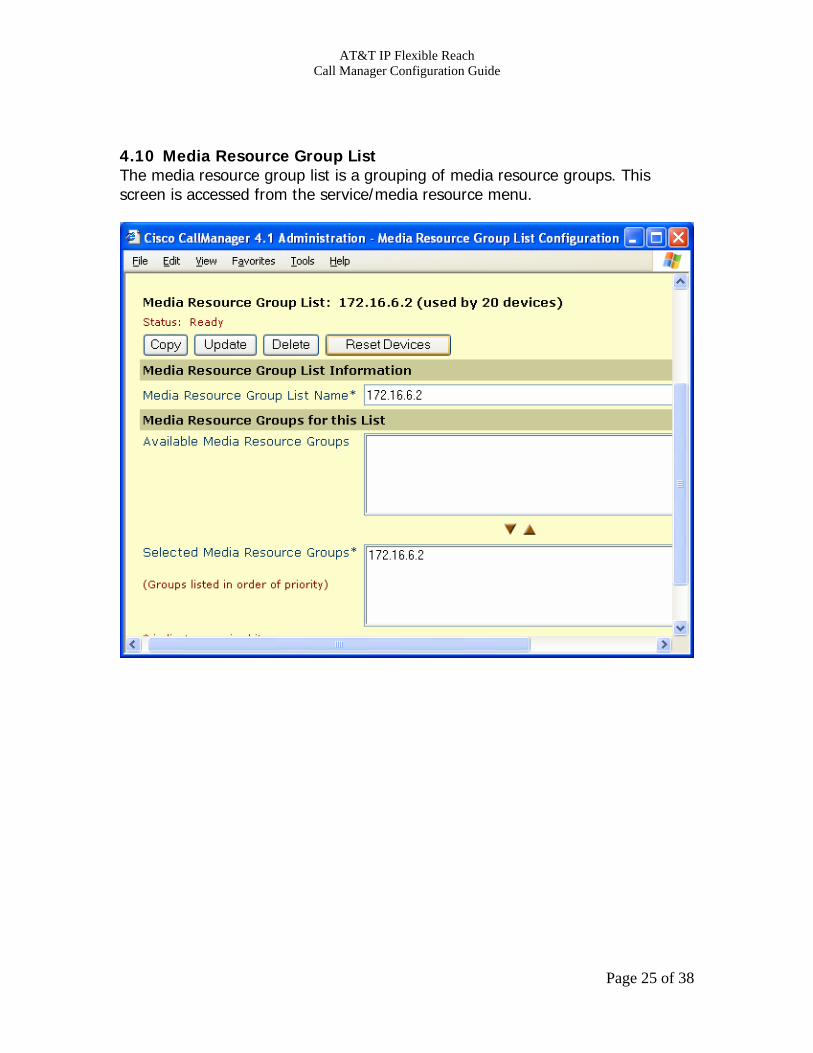
4.10 Media Resource Group List The media resource group list is a grouping of media resource groups. This screen is accessed from the service/media resource menu.
Page 25 of 38

AT&T IP Flexible Reach Call Manager Configuration Guide
4.11 Conference Bridge The conference bridge specifies the conferencing resources to be used by the Call Manager phone users when the phone’s conference button is selected. This screen is accessed from the service/media resource menu.
Page 26 of 38
AT&T IP Flexible Reach Call Manager Configuration Guide
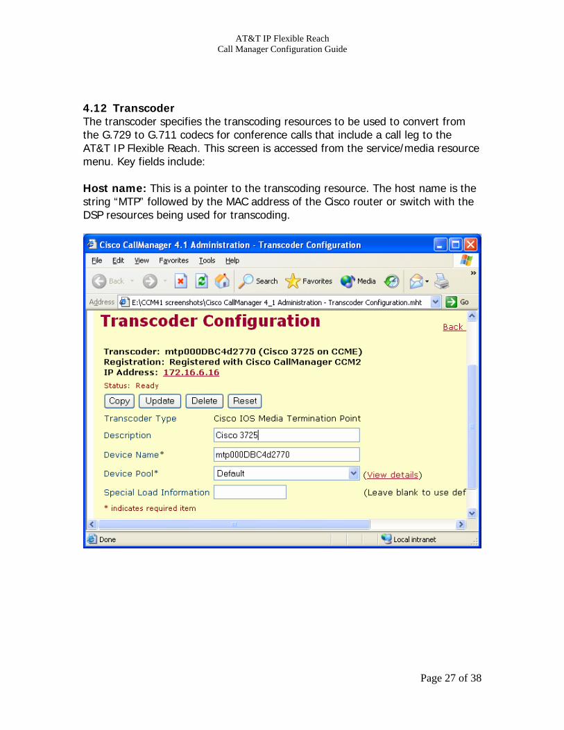
4.12 Transcoder The transcoder specifies the transcoding resources to be used to convert from the G.729 to G.711 codecs for conference calls that include a call leg to the AT&T IP Flexible Reach. This screen is accessed from the service/media resource menu. Key fields include: Host name: This is a pointer to the transcoding resource. The host name is the string “MTP” followed by the MAC address of the Cisco router or switch with the DSP resources being used for transcoding.
Page 27 of 38

AT&T IP Flexible Reach Call Manager Configuration Guide
4.13 Phone Configuration This screen specifies the parameters for the Call Manager phones. It is accessed from the Device menu. Key parameters are: Device Pool: This phone will use the parameters in the “default” device pool. Media Resource Group List: This phone will use the resources specifies in the designated Media Resource Group List which include the conference bridge and transcoder.
Page 28 of 38

AT&T IP Flexible Reach Call Manager Configuration Guide
4.14 Service Parameters This screen specifies the parameters for the Call Manager. It is accessed from the Service menu. The full list of service parameters are in the following attachment.
Cisco Unified CallManager 4_2 Administration - Service Parameters Configuration.mht Key parameters are: H225 TCP Timer: This specifies the amount of time Call Manager will wait after trying to open an H225 channel with the AT&T Border Element before attempting an alternate route. Check Progress Indicator Before Establishing Media: This parameter specifies that Call Manager must check the progress indicator in an alerting or progress message prior to establishing a media channel. This parameter must be set to “true”. Max Call Duration: This parameter specifies how long a call should last in minutes. The default is 720 (i.e. 12 hours). AT&T recommends that this parameter be set to “0” (no max call duration limit). Duplex Streaming: This parameter specifies whether 2 way voice streaming will occur when music on hold is implemented. AT&T requires that the default setting of “true” be used.
Page 29 of 38
AT&T IP Flexible Reach Call Manager Configuration Guide
5 IP Toll Free Specific Information This section provides information specific to IP Toll Free. 5.1 Call Flow with IP Call Center This section provides a typical call flow for the interaction between the AT&T IP Toll Free Service and the Cisco IP Call Center. Note that Cisco CVP (Cisco Voice Portal) is NOT currently supported. The components in this call flow include the following: • Call Manager - Call Manager is the Cisco IP PBX platform. Call Manager release
4.2.1 is supported for this application. • IP IVR – IP IVR is the Cisco IVR platform. This platform is used to play voice
prompts as needed based on information based from ICM. IP IVR release 4.0.4 is supported for this application.
• ICM – ICM is an IPCC scripting application. This application is used to script the flow of a customer’s IPCC application. ICM release 7.0 SR4 is supported for this application.
Page 30 of 38
AT&T IP Flexible Reach Call Manager Configuration Guide
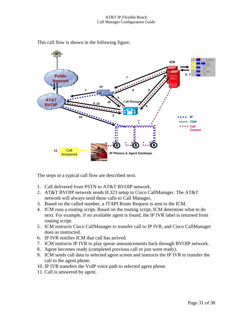
This call flow is shown in the following figure.
The steps in a typical call flow are described next. 1. Call delivered from PSTN to AT&T BVOIP network. 2. AT&T BVOIP network sends H.323 setup to Cisco CallManager. The AT&T
network will always send these calls to Call Manager, 3. Based on the called number, a JTAPI Route Request is sent to the ICM. 4. ICM runs a routing script. Based on the routing script, ICM determine what to do
next. For example, if no available agent is found, the IP IVR label is returned from routing script.
5. ICM instructs Cisco CallManager to transfer call to IP IVR, and Cisco CallManager does as instructed.
6. IP IVR notifies ICM that call has arrived. 7. ICM instructs IP IVR to play queue announcements back through BVOIP network. 8. Agent becomes ready (completed previous call or just went ready). 9. ICM sends call data to selected agent screen and instructs the IP IVR to transfer the
call to the agent phone. 10. IP IVR transfers the VoIP voice path to selected agent phone. 11. Call is answered by agent.
PPuubblliicc NNeettwwoorrkk
IP Phones & Agent Desktops
IP TDM Call Control
1
2
3 6
1111 Call Answered
4
7
7 , 7
IP-
Call Manager
IICCMM
5
5
5
10
AATT&&TT BBVVOOIIPP
10 ,10
N t k
Page 31 of 38

AT&T IP Flexible Reach Call Manager Configuration Guide
5.2 Examples for Call Manager Configuration for IPCC The following sections describe an example set of Call Manager configuration screens that can be used to access the Cisco IPCC application. However, these sections should be used as examples of how IP Toll Free dialed calls can be mapped to a Cisco IPCC application. The customer must consult Cisco documentation to determine the exact configuration they will require. In addition, this document does not cover configuration for ICM and IP IVR.
Page 32 of 38
AT&T IP Flexible Reach Call Manager Configuration Guide
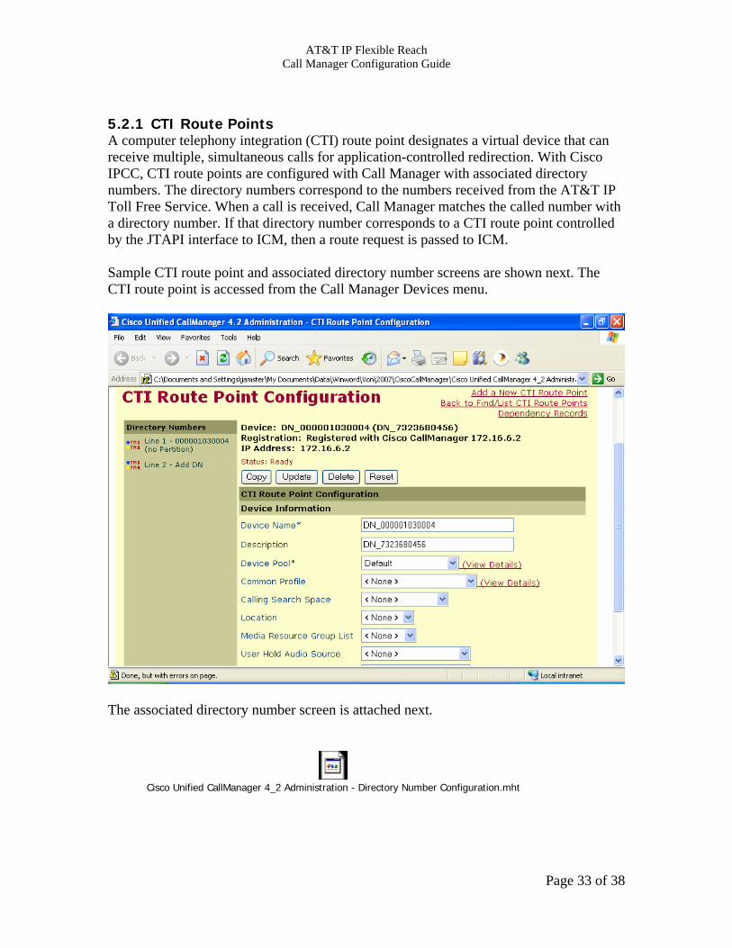
5.2.1 CTI Route Points A computer telephony integration (CTI) route point designates a virtual device that can receive multiple, simultaneous calls for application-controlled redirection. With Cisco IPCC, CTI route points are configured with Call Manager with associated directory numbers. The directory numbers correspond to the numbers received from the AT&T IP Toll Free Service. When a call is received, Call Manager matches the called number with a directory number. If that directory number corresponds to a CTI route point controlled by the JTAPI interface to ICM, then a route request is passed to ICM. Sample CTI route point and associated directory number screens are shown next. The CTI route point is accessed from the Call Manager Devices menu.
The associated directory number screen is attached next.
Cisco Unified CallManager 4_2 Administration - Directory Number Configuration.mht
Page 33 of 38

AT&T IP Flexible Reach Call Manager Configuration Guide
5.2.2 Incoming Call Routing for IP Toll Free For IP Toll Free, the AT&T network will send the call to the PBX using called number digits requested by the customer. This number will be prefixed with 5 leading zeroes. This number can be mapped to an internal extension or a CTI route point directory number on the translation pattern screen (see section 4.4). On the translation pattern screen, put the IP Toll Free called number string in the translation pattern field and put the internal extension or CTI route point directory number in the called party transform mask field.
Page 34 of 38
AT&T IP Flexible Reach Call Manager Configuration Guide
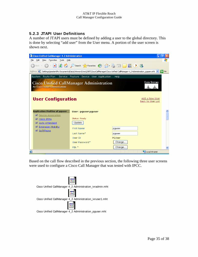
5.2.3 JTAPI User Definitions A number of JTAPI users must be defined by adding a user to the global directory. This is done by selecting “add user” from the User menu. A portion of the user screen is shown next.
Based on the call flow described in the previous section, the following three user screens were used to configure a Cisco Call Manager that was tested with IPCC.
Cisco Unified CallManager 4_2 Administration_ivradmin.mht
Cisco Unified CallManager 4_2 Administration_ivruser1.mht
Cisco Unified CallManager 4_2 Administration_pguser.mht
Page 35 of 38

AT&T IP Flexible Reach Call Manager Configuration Guide
6 Appendix A: Router Version/Configuration for Transcoding
6.1 Router Version AT&T has tested 12.3.11T for transcoding support with Cisco Call Manager. A sample “show version” output is shown next. Cisco IOS Software, 3700 Software (C3725-IPVOICE-M), Version 12.3(11)T, RELEASE SOFTWARE (fc2) Technical Support: http://www.cisco.com/techsupport Copyright (c) 1986-2004 by Cisco Systems, Inc. Compiled Sat 18-Sep-04 16:10 by eaarmas ROM: System Bootstrap, Version 12.2(8r)T2, RELEASE SOFTWARE (fc1) v00ccm03-3725 uptime is 5 weeks, 2 hours, 31 minutes System returned to ROM by power-on System restarted at 18:14:02 UTC Tue Mar 8 2005 System image file is "flash:c3725-ipvoice-mz.123-11.T.bin" 6.2 Transcoding Configuration The router configuration for transcoding is shown next. ! Sets dsp services in voice card in slot 1 voice-card 1 no dspfarm dsp services dspfarm ! Connection to Call Manager sccp local FastEthernet0/0 sccp sccp ccm 172.16.6.2 priority 1 ! ! Maximum number of calls for transcoder. dspfarm transcoder maximum sessions 12 !
Page 36 of 38

AT&T IP Flexible Reach Call Manager Configuration Guide
7 Appendix B: Firewall Rules If the customer implements a firewall, then the following access control rules shall be required. 1) Accept AT&T Border Element traffic from TCP ports >1023 2) Accept AT&T Border Elements traffic from UDP ports 16384-32767
Page 37 of 38

AT&T IP Flexible Reach Call Manager Configuration Guide
Page 38 of 38
This Customer Configuration Guide ("CCG") is offered as a convenience to AT&T's customers. The specifications and information regarding the product in this CCG are subject to change without notice. All statements, information, and recommendations in this CCG are believed to be accurate but are presented without warranty of any kind, express or implied, and are provided “AS IS”. Users must take full responsibility for the application of the specifications and information in this CCG. In no event shall AT&T or its suppliers be liable for any indirect, special, consequential, or incidental damages, including, without limitation, lost profits or loss or damage arising out of the use or inability to use this CCG, even if AT&T or its suppliers have been advised of the possibility of such damage.