attachement of heavy claddings over foarm with and without
TRANSCRIPT
Home Innovation Research Labs DRAFT – May 2019 Attachment of Heavyweight Claddings over FPIS 1
ATTACHMENT OF HEAVY CLADDINGS OVER FOAM WITH AND WITHOUT DRAINAGE GAPS
Project Results and Conclusions
Prepared For
USDA Forest Products Laboratory
under U.S. Forest Service Joint Venture Agreement 17-JV-11111135-028
with additional funding from
National Association of Home Builders American Chemistry Council
P. Gunderson and K. Kaufmann
March 2020
400 Prince George’s Blvd. | Upper Marlboro, MD 20774 | 800.638.8556 | HomeInnovation.com

Disclaimer
Neither Home Innovation Research Labs, Inc., nor any person acting on its behalf, makes any warranty, expressed or implied, with respect to the use of any information, apparatus, method, or process disclosed in this publication or that such use may not infringe privately owned rights, or assumes any liabilities with respect to the use of, or for damages resulting from the use of, any information, apparatus, method, or process disclosed in this publication, or is responsible for statements made or opinions expressed by individual authors.
Condition/Limitation of Use
Home Innovation Research Labs is accredited by IAS in accordance with ISO 17020, 17025, and ISO Guide 65. The test methods within this report are included in the scope of accreditation.
This report may be distributed in its entirety, but excerpted portions shall not be distributed without prior written approval of Home Innovation Research Labs.
Acknowledgements
Thanks to our Advisory Group members for their time and expertise: Jay Crandell, ARES (rep. American Chemistry Council); Brian Lieburn and Theresa Weston, DuPont; Jay Murdoch, Owens Corning; Kevin Wensel, Stucco Manufacturers Association; Brock Osborn and Tom Remmele, Sto Corp; Mike Woodin, Pacific Plastering; Rob Aird, Aird Incorporated; Jason Thompson, National Concrete Masonry Association; Gary Ehrlich and Jon Sukonik, National Association of Home Builders; Rick Allen, International Staple, Nail, and Tool Association; Anthony Versino, Illinois Tool Works; Phil Line, American Wood Council; Borjen “BJ” Yeh, APA – The Engineered Wood Association; Sam Glass, USDA Forest Products Laboratory; Max Rietschier, Kingspan Insulation; Mark Williams, Williams Building Diagnostics; Jason Wigboldy, Rodenhouse, Inc.
Thanks to the following companies for donated materials, equipment or expertise: Aird, Inc. – expert stucco application Kris Kreple, Atlas EPS – Foam Plastic Insulative Sheathing (FPIS) Beck America (FASCO); Kyocera-Senco (Senco); Peace Industries (Spotnails) – staples and pneumatic staplers Rodenhouse, Inc. – washers, nails, screws, and specialized power-drivers Structa Wire Corp. – specialized lath Stuc-Co-Flex International, Inc. – entangled filament drainage mats

Home Innovation Research Labs March 2020 Attachment of Heavy Claddings over Foam i
EXECUTIVE SUMMARY This research by Home Innovation Research Labs was conducted with support from the USDA Forest Service Forest Products Laboratory. Additional funders include the National Association of Home Builders, Construction Technology and Research Sub Committee (CTRSC) and the American Chemistry Council.
The aim of this research was to identify alternate and/or expanded design and installation guidance for the application of heavyweight claddings such as stucco and adhered masonry veneers over rigid foam insulation on light-frame walls and potentially provide the basis for follow-on qualification testing to support a future code proposal.
Wall samples were tested in the lab for deflection and cracking due to gravity loading. The baseline set of specimens was designed to inform potential calibration of the TR-12 dowel equations for the unique case of cementitious claddings which include minimal penetration of the fastener through the material and transfer of the cladding load to the fastener via an embedded lath substrate. Three fastener types were tested: staples, nails and screws. Additional lines of inquiry introduced drainage gaps into the wall assembly and tested the effect of foam thickness and lath type. Test matrix details subsequent to the baseline set were adjusted in response to demonstrated performance and to more fully explore opportunities for highly constructible or effective configurations.
Summary of Results
1. A modified TR-12 dowel equation produced estimated capacities within approximately 20% of measured performance for most configurations.
2. The gravity load performance of heavyweight cementitious claddings appears to have a strong system effect or fastener group effect – a “community effect” – (not directly dependent on the dowel characteristics) whereby the per fastener capacity can be increased by more frequent, uniform distribution.
3. Power-driven staples are a promising approach to fastening lath to wall substrates to support heavyweight cementitious cladding. More numerous fasteners appear to transfer the failure mode from individual points of connection to a diffuse mechanism that relies on the systemic performance of the embedded lath/stucco combination, which may explain the stronger-than-expected performance of staples in the configurations with no stud penetration and the slightly weaker-than-expected performance of screws (limited to 16-in. o.c. lateral frequency).
4. As expected, the addition of a washer improved performance. The method of using power-driven screws and nails in combination with washers increased installation speed. The additional strength attained by using a washer varied significantly across configurations, apparently due to the interaction between the nail/screw head and the washer.
March 2020 Home Innovation Research Labs ii Attachment of Heavy Claddings over Foam
LIST OF ABBREVIATIONS
CI Continuous insulation—generally a rigid or semi-rigid board insulation material installed exterior to the wall cavity.
CZ Climate Zone, as defined by the International Energy Conservation Code
EPS Expanded Polystyrene, a type of rigid foam sheathing
FPIS Foam Plastic Insulating Sheathing (FPIS) – a rigid foam board typically made from extruded polystyrene (XPS), expanded polystyrene (EPS) or Polyisocyanurate (PIC) and used to provide a layer of continuous insulation for house walls or other components. In this report, FPIS generally refers to rigid foam installed as continuous insulation exterior to the wood sheathing, or in place of the wood sheathing.
High-R Building Industry reference to wall systems with high thermal resistance, exceeding energy code minimum requirements
IECC International Energy Conservation Code
IRC International Residential Code
o.c. On center – the measurement for lumber with dimension, e.g., studs, whose 1-1/2-in. width means that 16-in. o.c. installation leaves a 14-1/2-in. stud bay.
OSB Oriented Strand Board, a manufactured wood structural panel sheathing product
psf Pounds per square foot, a measure of weight for heavyweight cementitious claddings
psy Pounds per square yard, a measure of weight for diamond mesh stucco netting or lath
R-value Quantitative measure of resistance to conductive heat flow (h∙°F∙ft2/Btu)
U-value Quantitative measure of thermal conductance: Btu /(h∙°F∙ft2) (the inverse of R-value)
SPF Spruce-pine-fir (SPF) lumber, a high-grade framing lumber that can include any one of these three types of trees
WRB Water-Resistive Barrier or Weather-Resistant Barrier (WRB) is a material providing a drainage surface to protect the wall assembly from rainwater.
WSP Wood Structural Panel — the layer of wood sheathing (plywood or OSB) that provides shear and racking strength when properly attached to wall framing
XPS Extruded Polystyrene, a type of rigid foam sheathing

Home Innovation Research Labs March 2020 Attachment of Heavyweight Claddings over FPIS iii
TABLE OF CONTENTS
EXECUTIVE SUMMARY ...................................................................................................................... I
Summary of Results ...................................................................................................................... i
BACKGROUND .................................................................................................................................. 5
Introduction ................................................................................................................................. 5
Objectives .................................................................................................................................... 5
Goals ............................................................................................................................................ 5
Current Guidance ......................................................................................................................... 6
EXPERIMENTAL DESIGN ................................................................................................................... 7
Specimen Naming Convention ..................................................................................................... 8
Specimen Construction ................................................................................................................ 9
Baseline Parameters ................................................................................................................ 9
Research Goals ....................................................................................................................... 10
Predicted Capacity ................................................................................................................. 10
Results ........................................................................................................................................ 10
Nails ........................................................................................................................................ 11
Screws .................................................................................................................................... 23
Staples .................................................................................................................................... 26
Predictive Calculations: .......................................................................................................... 33
Phase II: Aging and Weathering ................................................................................................. 34
Methodology .............................................................................................................................. 34
Construction ........................................................................................................................... 34
Observations .............................................................................................................................. 36
RECOMMENDATIONS .................................................................................................................... 39
APPENDIX ....................................................................................................................................... 41
Test Specimen Construction and Preparation ....................................................................... 41
Standards and Code References ............................................................................................ 43
Test Procedures and Equipment ............................................................................................ 44
Test Plan ................................................................................................................................. 46
Specimen Materials ............................................................................................................... 47

March 2020 Home Innovation Research Labs iv Attachment of Heavyweight Claddings over FPIS
Page Intentionally left Blank
Home Innovation Research Labs March 2020 Attachment of Heavyweight Claddings over FPIS 5
BACKGROUND
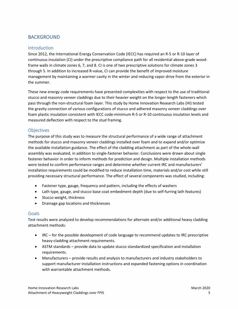
Introduction Since 2012, the International Energy Conservation Code (IECC) has required an R-5 or R-10 layer of continuous insulation (CI) under the prescriptive compliance path for all residential above-grade wood-frame walls in climate zones 6, 7, and 8. CI is one of two prescriptive solutions for climate zones 3 through 5. In addition to increased R-value, CI can provide the benefit of improved moisture management by maintaining a warmer cavity in the winter and reducing vapor drive from the exterior in the summer.
These new energy code requirements have presented complexities with respect to the use of traditional stucco and masonry veneer claddings due to their heavier weight on the longer-length fasteners which pass through the non-structural foam layer. This study by Home Innovation Research Labs (HI) tested the gravity connection of various configurations of stucco and adhered masonry veneer claddings over foam plastic insulation consistent with IECC code-minimum R-5 or R-10 continuous insulation levels and measured deflection with respect to the stud framing.
Objectives The purpose of this study was to measure the structural performance of a wide range of attachment methods for stucco and masonry veneer claddings installed over foam and to expand and/or optimize the available installation guidance. The effect of the cladding attachment as part of the whole-wall assembly was evaluated, in addition to single-fastener behavior. Conclusions were drawn about single fastener behavior in order to inform methods for prediction and design. Multiple installation methods were tested to confirm performance ranges and determine whether current IRC and manufacturers’ installation requirements could be modified to reduce installation time, materials and/or cost while still providing necessary structural performance. The effect of several components was studied, including:
• Fastener type, gauge, frequency and pattern, including the effects of washers • Lath type, gauge, and stucco base coat embedment depth (due to self-furring lath features) • Stucco weight, thickness • Drainage gap locations and thicknesses
Goals Test results were analyzed to develop recommendations for alternate and/or additional heavy cladding attachment methods:
• IRC – for the possible development of code language to recommend updates to IRC prescriptive heavy-cladding attachment requirements.
• ASTM standards – provide data to update stucco standardized specification and installation requirements.
• Manufacturers – provide results and analysis to manufacturers and industry stakeholders to support manufacturer installation instructions and expanded fastening options in coordination with warrantable attachment methods.
March 2020 Home Innovation Research Labs 6 Attachment of Heavyweight Claddings over FPIS
Current Guidance Two ASTM Standard Specifications guide installation of cementitious claddings over light-frame wood walls: C926 “Application of Portland Cement-Based Plaster” and C1063 “Installation of Lathing and Furring to Receive Interior and Exterior Portland Cement-Based Plaster.” These standards do not address the use of a layer of rigid foam exterior continuous insulation behind the cladding.
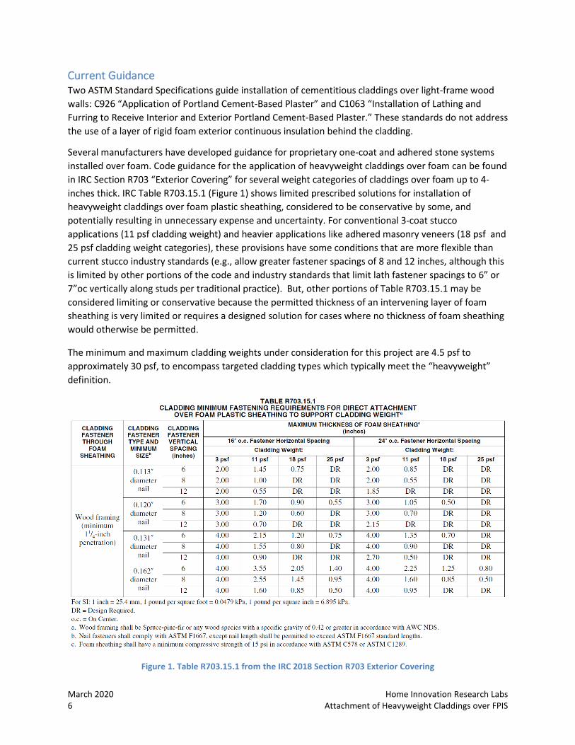
Several manufacturers have developed guidance for proprietary one-coat and adhered stone systems installed over foam. Code guidance for the application of heavyweight claddings over foam can be found in IRC Section R703 “Exterior Covering” for several weight categories of claddings over foam up to 4-inches thick. IRC Table R703.15.1 (Figure 1) shows limited prescribed solutions for installation of heavyweight claddings over foam plastic sheathing, considered to be conservative by some, and potentially resulting in unnecessary expense and uncertainty. For conventional 3-coat stucco applications (11 psf cladding weight) and heavier applications like adhered masonry veneers (18 psf and 25 psf cladding weight categories), these provisions have some conditions that are more flexible than current stucco industry standards (e.g., allow greater fastener spacings of 8 and 12 inches, although this is limited by other portions of the code and industry standards that limit lath fastener spacings to 6” or 7”oc vertically along studs per traditional practice). But, other portions of Table R703.15.1 may be considered limiting or conservative because the permitted thickness of an intervening layer of foam sheathing is very limited or requires a designed solution for cases where no thickness of foam sheathing would otherwise be permitted.
The minimum and maximum cladding weights under consideration for this project are 4.5 psf to approximately 30 psf, to encompass targeted cladding types which typically meet the “heavyweight” definition.
Figure 1. Table R703.15.1 from the IRC 2018 Section R703 Exterior Covering
Home Innovation Research Labs March 2020 Attachment of Heavyweight Claddings over FPIS 7
EXPERIMENTAL DESIGN Heavyweight cementitious claddings were installed over rigid foam sheathing per typical field practice and following the underlying methodology of IRC Table 703.15.1 to represent the most common wall configurations as determined by the project team in consultation with the Advisory Group (AG). The test specimens were then subjected to destructive testing to achieve the following overarching goals:
1. Establish each wall system’s strength under gravity loading, based on predetermined deflection thresholds.
2. Compare each wall system’s tested performance to the predictions which were used to develop the current installation requirements, based on theoretical analysis and assumptions of fastener behavior unique to heavyweight cementitious claddings (TR-12 equations).
3. Provide installation recommendations for heavy-weight cementitious claddings over rigid foam CI as applicable to an industry-responsive variety of lath, fastener and drainage gap choices.
4. Identify opportunities to modify existing methods or develop new approaches of fastener installation which yield acceptable performance with reduced effort, time, or cost.
March 2020 Home Innovation Research Labs 8 Attachment of Heavyweight Claddings over FPIS
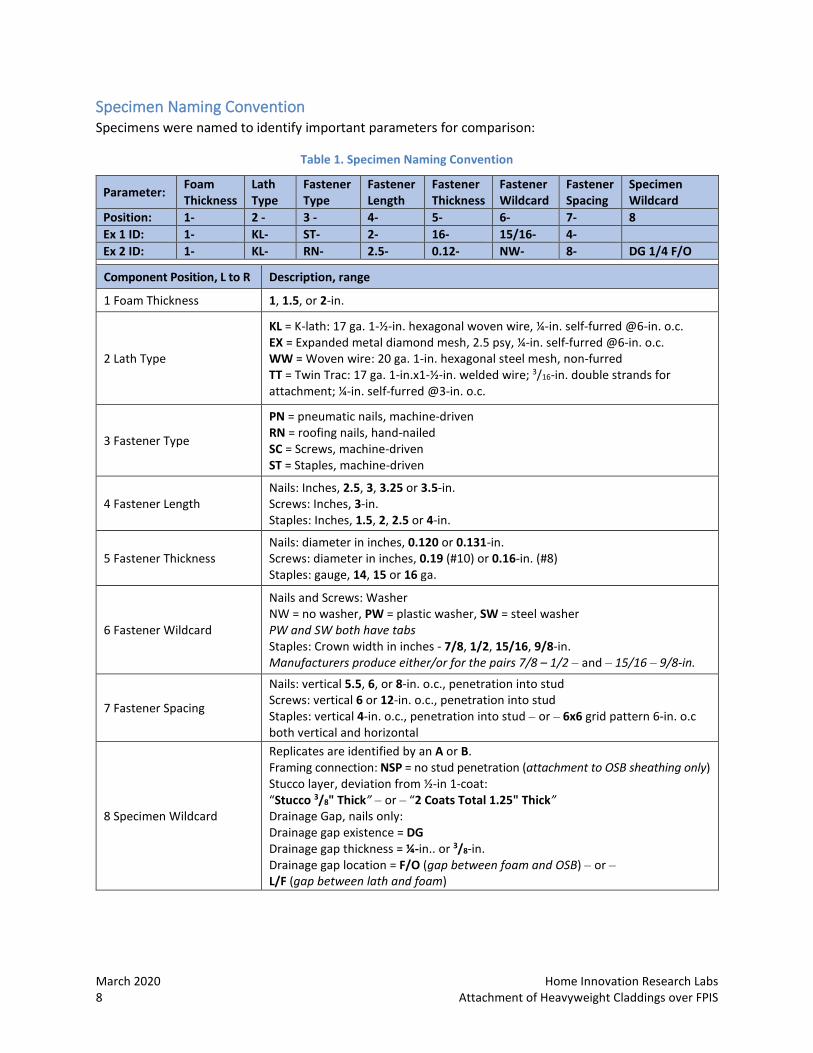
Specimen Naming Convention Specimens were named to identify important parameters for comparison:
Table 1. Specimen Naming Convention
Parameter: Foam Thickness
Lath Type
Fastener Type
Fastener Length
Fastener Thickness
Fastener Wildcard
Fastener Spacing
Specimen Wildcard
Position: 1- 2 - 3 - 4- 5- 6- 7- 8 Ex 1 ID: 1- KL- ST- 2- 16- 15/16- 4- Ex 2 ID: 1- KL- RN- 2.5- 0.12- NW- 8- DG 1/4 F/O Component Position, L to R Description, range
1 Foam Thickness 1, 1.5, or 2-in.
2 Lath Type
KL = K-lath: 17 ga. 1-½-in. hexagonal woven wire, ¼-in. self-furred @6-in. o.c. EX = Expanded metal diamond mesh, 2.5 psy, ¼-in. self-furred @6-in. o.c. WW = Woven wire: 20 ga. 1-in. hexagonal steel mesh, non-furred TT = Twin Trac: 17 ga. 1-in.x1-½-in. welded wire; 3/16-in. double strands for attachment; ¼-in. self-furred @3-in. o.c.
3 Fastener Type
PN = pneumatic nails, machine-driven RN = roofing nails, hand-nailed SC = Screws, machine-driven ST = Staples, machine-driven
4 Fastener Length Nails: Inches, 2.5, 3, 3.25 or 3.5-in. Screws: Inches, 3-in. Staples: Inches, 1.5, 2, 2.5 or 4-in.
5 Fastener Thickness Nails: diameter in inches, 0.120 or 0.131-in. Screws: diameter in inches, 0.19 (#10) or 0.16-in. (#8) Staples: gauge, 14, 15 or 16 ga.
6 Fastener Wildcard
Nails and Screws: Washer NW = no washer, PW = plastic washer, SW = steel washer PW and SW both have tabs Staples: Crown width in inches - 7/8, 1/2, 15/16, 9/8-in. Manufacturers produce either/or for the pairs 7/8 – 1/2 – and – 15/16 – 9/8-in.
7 Fastener Spacing
Nails: vertical 5.5, 6, or 8-in. o.c., penetration into stud Screws: vertical 6 or 12-in. o.c., penetration into stud Staples: vertical 4-in. o.c., penetration into stud – or – 6x6 grid pattern 6-in. o.c both vertical and horizontal
8 Specimen Wildcard
Replicates are identified by an A or B. Framing connection: NSP = no stud penetration (attachment to OSB sheathing only) Stucco layer, deviation from ½-in 1-coat: “Stucco 3/8" Thick” – or – “2 Coats Total 1.25" Thick” Drainage Gap, nails only: Drainage gap existence = DG Drainage gap thickness = ¼-in.. or 3/8-in. Drainage gap location = F/O (gap between foam and OSB) – or – L/F (gap between lath and foam)
Home Innovation Research Labs March 2020 Attachment of Heavyweight Claddings over FPIS 9
Specimen Construction
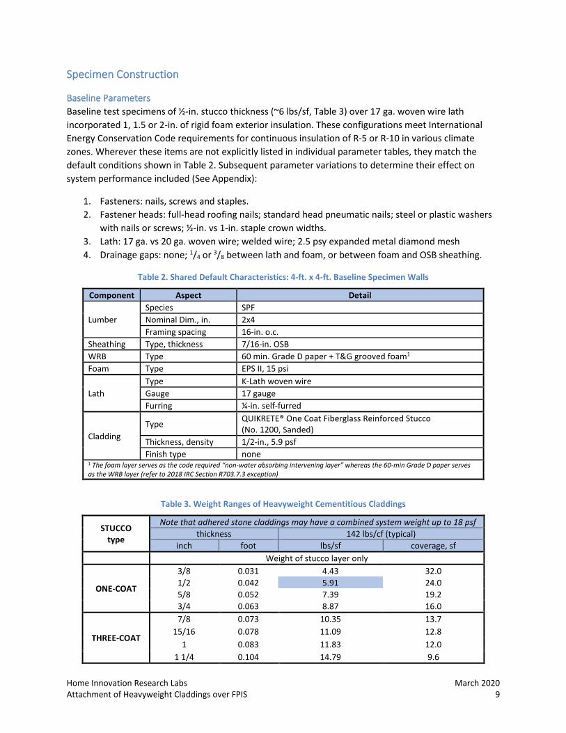
Baseline Parameters Baseline test specimens of ½-in. stucco thickness (~6 lbs/sf, Table 3) over 17 ga. woven wire lath incorporated 1, 1.5 or 2-in. of rigid foam exterior insulation. These configurations meet International Energy Conservation Code requirements for continuous insulation of R-5 or R-10 in various climate zones. Wherever these items are not explicitly listed in individual parameter tables, they match the default conditions shown in Table 2. Subsequent parameter variations to determine their effect on system performance included (See Appendix):
1. Fasteners: nails, screws and staples. 2. Fastener heads: full-head roofing nails; standard head pneumatic nails; steel or plastic washers
with nails or screws; ½-in. vs 1-in. staple crown widths. 3. Lath: 17 ga. vs 20 ga. woven wire; welded wire; 2.5 psy expanded metal diamond mesh 4. Drainage gaps: none; 1/4 or 3/8 between lath and foam, or between foam and OSB sheathing.
Table 2. Shared Default Characteristics: 4-ft. x 4-ft. Baseline Specimen Walls
Component Aspect Detail
Lumber Species SPF Nominal Dim., in. 2x4 Framing spacing 16-in. o.c.
Sheathing Type, thickness 7/16-in. OSB WRB Type 60 min. Grade D paper + T&G grooved foam1 Foam Type EPS II, 15 psi
Lath Type K-Lath woven wire Gauge 17 gauge Furring ¼-in. self-furred
Cladding Type QUIKRETE® One Coat Fiberglass Reinforced Stucco
(No. 1200, Sanded) Thickness, density 1/2-in., 5.9 psf Finish type none
1 The foam layer serves as the code required “non-water absorbing intervening layer” whereas the 60-min Grade D paper serves as the WRB layer (refer to 2018 IRC Section R703.7.3 exception)
Table 3. Weight Ranges of Heavyweight Cementitious Claddings
STUCCO type
Note that adhered stone claddings may have a combined system weight up to 18 psf thickness 142 lbs/cf (typical)
inch foot lbs/sf coverage, sf Weight of stucco layer only
ONE-COAT
3/8 0.031 4.43 32.0 1/2 0.042 5.91 24.0 5/8 0.052 7.39 19.2 3/4 0.063 8.87 16.0
THREE-COAT
7/8 0.073 10.35 13.7 15/16 0.078 11.09 12.8
1 0.083 11.83 12.0 1 1/4 0.104 14.79 9.6
March 2020 Home Innovation Research Labs 10 Attachment of Heavyweight Claddings over FPIS
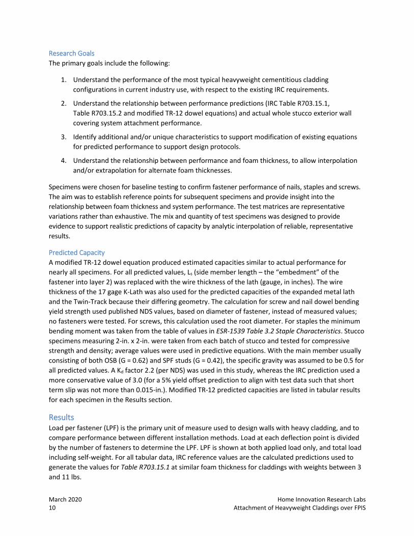
Research Goals The primary goals include the following:
1. Understand the performance of the most typical heavyweight cementitious cladding configurations in current industry use, with respect to the existing IRC requirements.
2. Understand the relationship between performance predictions (IRC Table R703.15.1, Table R703.15.2 and modified TR-12 dowel equations) and actual whole stucco exterior wall covering system attachment performance.
3. Identify additional and/or unique characteristics to support modification of existing equations for predicted performance to support design protocols.
4. Understand the relationship between performance and foam thickness, to allow interpolation and/or extrapolation for alternate foam thicknesses.
Specimens were chosen for baseline testing to confirm fastener performance of nails, staples and screws. The aim was to establish reference points for subsequent specimens and provide insight into the relationship between foam thickness and system performance. The test matrices are representative variations rather than exhaustive. The mix and quantity of test specimens was designed to provide evidence to support realistic predictions of capacity by analytic interpolation of reliable, representative results.
Predicted Capacity A modified TR-12 dowel equation produced estimated capacities similar to actual performance for nearly all specimens. For all predicted values, Ls (side member length – the “embedment” of the fastener into layer 2) was replaced with the wire thickness of the lath (gauge, in inches). The wire thickness of the 17 gage K-Lath was also used for the predicted capacities of the expanded metal lath and the Twin-Track because their differing geometry. The calculation for screw and nail dowel bending yield strength used published NDS values, based on diameter of fastener, instead of measured values; no fasteners were tested. For screws, this calculation used the root diameter. For staples the minimum bending moment was taken from the table of values in ESR-1539 Table 3.2 Staple Characteristics. Stucco specimens measuring 2-in. x 2-in. were taken from each batch of stucco and tested for compressive strength and density; average values were used in predictive equations. With the main member usually consisting of both OSB (G = 0.62) and SPF studs (G = 0.42), the specific gravity was assumed to be 0.5 for all predicted values. A Kd factor 2.2 (per NDS) was used in this study, whereas the IRC prediction used a more conservative value of 3.0 (for a 5% yield offset prediction to align with test data such that short term slip was not more than 0.015-in.). Modified TR-12 predicted capacities are listed in tabular results for each specimen in the Results section.
Results Load per fastener (LPF) is the primary unit of measure used to design walls with heavy cladding, and to compare performance between different installation methods. Load at each deflection point is divided by the number of fasteners to determine the LPF. LPF is shown at both applied load only, and total load including self-weight. For all tabular data, IRC reference values are the calculated predictions used to generate the values for Table R703.15.1 at similar foam thickness for claddings with weights between 3 and 11 lbs.
Home Innovation Research Labs March 2020 Attachment of Heavyweight Claddings over FPIS 11
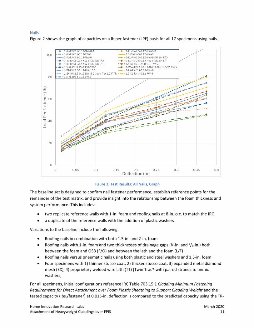
Nails Figure 2 shows the graph of capacities on a lb per fastener (LPF) basis for all 17 specimens using nails.
Figure 2. Test Results: All Nails, Graph
The baseline set is designed to confirm nail fastener performance, establish reference points for the remainder of the test matrix, and provide insight into the relationship between the foam thickness and system performance. This includes:
• two replicate reference walls with 1-in. foam and roofing nails at 8-in. o.c. to match the IRC • a duplicate of the reference walls with the addition of plastic washers
Variations to the baseline include the following:
• Roofing nails in combination with both 1.5-in. and 2-in. foam • Roofing nails with 1-in. foam and two thicknesses of drainage gaps (¼-in. and 3/8-in.) both
between the foam and OSB (F/O) and between the lath and the foam (L/F) • Roofing nails versus pneumatic nails using both plastic and steel washers and 1.5-in. foam • Four specimens with 1) thinner stucco coat, 2) thicker stucco coat, 3) expanded metal diamond
mesh (EX), 4) proprietary welded wire lath (TT) [Twin Trac® with paired strands to mimic washers]
For all specimens, initial configurations reference IRC Table 703.15.1 Cladding Minimum Fastening Requirements for Direct Attachment over Foam Plastic Sheathing to Support Cladding Weight and the tested capacity (lbs./fastener) at 0.015-in. deflection is compared to the predicted capacity using the TR-
March 2020 Home Innovation Research Labs 12 Attachment of Heavyweight Claddings over FPIS
12 equation. “Wood Framing Penetration” is taken to be the full length of the fastener, including both the OSB and the framing in calculation of the penetration depth.
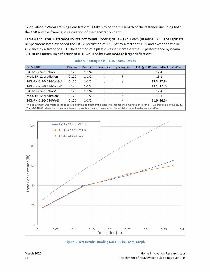
Table 4 and Error! Reference source not found. Roofing Nails – 1-in. Foam (Baseline [BL]): The replicate BL specimens both exceeded the TR-12 prediction of 13.1 psf by a factor of 1.35 and exceeded the IRC guidance by a factor of 1.61. The addition of a plastic washer increased the BL performance by nearly 50% at the minimum deflection of 0.015-in. and by even more at larger deflections.
Table 4. Roofing Nails – 1-in. Foam, Results
COMPARE Dia., in. Pen., in. Foam, in. Spacing, in. LPF @ 0.015-in. deflect. (w/self-wt) IRC basis calculation 0.120 1-1/4 1 8 12.4 Mod. TR-12 prediction 0.120 1-1/2 1 8 13.1 1-KL-RN-2.5-0.12-NW-8-A 0.120 1-1/2 1 8 13.3 (17.8) 1-KL-RN-2.5-0.12-NW-8-B 0.120 1-1/2 1 8 13.1 (17.7) IRC basis calculation* 0.120 1-1/4 1 8 12.4 Mod. TR-12 prediction* 0.120 1-1/2 1 8 13.1 1-KL-RN-2.5-0.12-PW-8 0.120 1-1/2 1 8 21.9 (26.3) *No adjustment was made to the calculation for the addition of the plastic washer for the IRC provisions or the TR-12 prediction of this study. The NDS/TR-12 calculation procedure does not provide a means to account for beneficial fastener head or washer effects.
Figure 3. Test Results: Roofing Nails – 1-in. Foam, Graph
Home Innovation Research Labs March 2020 Attachment of Heavyweight Claddings over FPIS 13
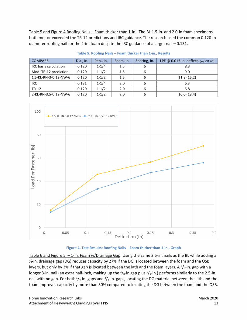
Table 5 and Figure 4 Roofing Nails – Foam thicker than 1-in.: The BL 1.5-in. and 2.0-in foam specimens both met or exceeded the TR-12 predictions and IRC guidance. The research used the common 0.120-in diameter roofing nail for the 2-in. foam despite the IRC guidance of a larger nail – 0.131.
Table 5. Roofing Nails – Foam thicker than 1-in., Results
COMPARE Dia., in. Pen., in. Foam, in. Spacing, in. LPF @ 0.015-in. deflect. (w/self-wt) IRC basis calculation 0.120 1-1/4 1.5 6 8.3 Mod. TR-12 prediction 0.120 1-1/2 1.5 6 9.0 1.5-KL-RN-3-0.12-NW-6 0.120 1-1/2 1.5 6 11.8 (15.2) IRC 0.131 1-1/4 2.0 6 6.3 TR-12 0.120 1-1/2 2.0 6 6.8 2-KL-RN-3.5-0.12-NW-6 0.120 1-1/2 2.0 6 10.0 (13.4)
Figure 4. Test Results: Roofing Nails – Foam thicker than 1-in., Graph
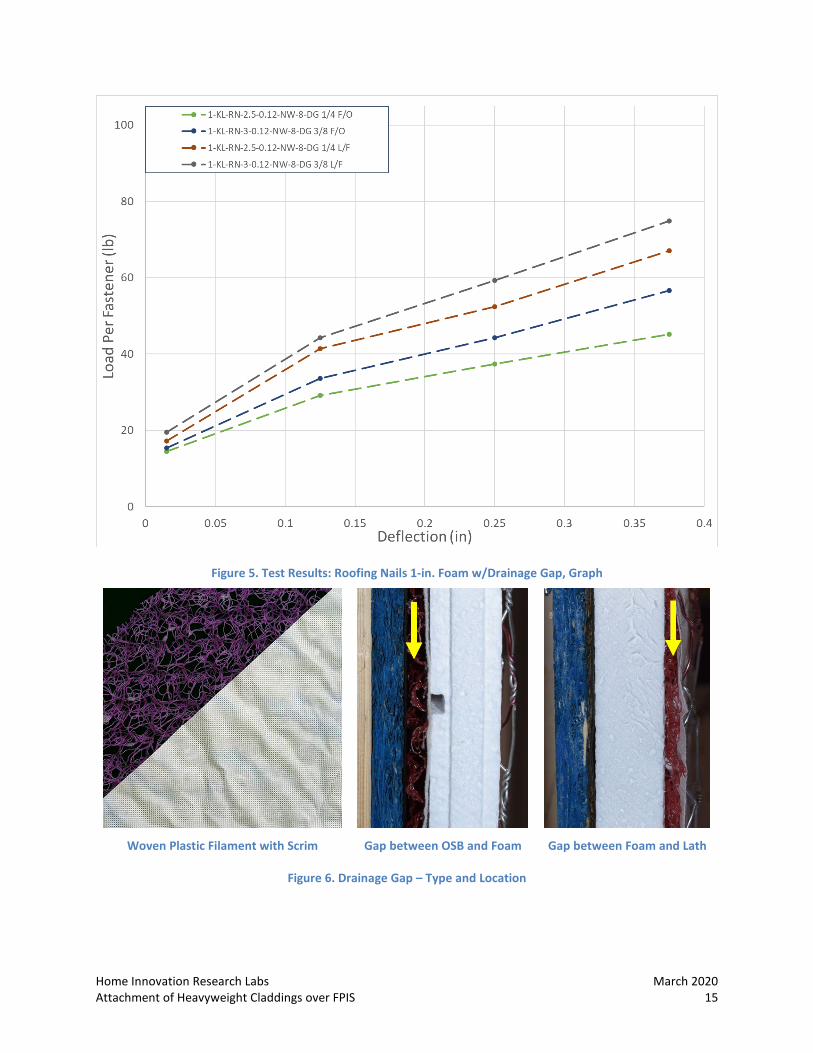
Table 6 and Figure 5 – 1-in. Foam w/Drainage Gap: Using the same 2.5-in. nails as the BL while adding a ¼-in. drainage gap (DG) reduces capacity by 27% if the DG is located between the foam and the OSB layers, but only by 3% if that gap is located between the lath and the foam layers. A 3/8-in. gap with a longer 3-in. nail (an extra half-inch, making up the 3/8-in gap plus 1/8-in.) performs similarly to the 2.5-in. nail with no gap. For both 1/4-in. gaps and 3/8-in. gaps, locating the DG material between the lath and the foam improves capacity by more than 30% compared to locating the DG between the foam and the OSB.
March 2020 Home Innovation Research Labs 14 Attachment of Heavyweight Claddings over FPIS
For the case with drainage gaps located between the foam and OSB, the TR-12 predictions appear reasonably consistent with the test data, slightly over-predicting capacity in the case of applied load not including self-weight for the ¼-in. DG. However, for the cases with the drainage gap between the lath and foam, the TR-12 predictions conservatively under-predicted the tested deflection-controlled capacity. More testing is advisable to better quantify and confirm these trends, especially any benefit associated with the location of the drainage gap. Otherwise, it appears that predictions can be reasonably (or conservatively) applied to both conditions without distinction provided that the total gap width (up to 3/8” more than the foam thickness per this testing) is accounted for in the predictions.
Table 6. 1-in. Foam w/Drainage Gap, Results (Lbs./fastener, LPF)
COMPARE Dia., in. Pen., in. Foam, in. Spacing, in. LPF @ 0.015-in.
deflect. (w/self-wt) Baseline avg (No DG) 0.120 1-1/2 1 8 13.2 (17.75)
1/4-in. Drainage Gap between Foam and OSB 1-KL-RN-2.5-0.12-NW-8-DG 1/4 F/O* 0.120 1-1/4 1 8 9.7 (14.5) Mod. TR-12 prediction 0.120 1-1/4 1 8 10.7 3/8-in. Drainage Gap between Foam and OSB 1-KL-RN-3-0.12-NW-8-DG 3/8 F/O# 0.120 1-5/8 1 8 10.8 (15.4) Mod. TR-12 prediction 0.120 1-5/8 1 8 9.7 1/4-in. Drainage Gap between Lath and Foam 1-KL-RN-2.5-0.12-NW-8-DG 1/4 L/F* 0.120 1-1/4 1 8 12.8 (17.3) Mod. TR-12 prediction 0.120 1-1/4 1 8 10.7 3/8-in. Drainage Gap between Lath and Foam 1-KL-RN-3-0.12-NW-8-DG 3/8 L/F# 0.120 1-5/8 1 8 14.1 (19.5) Mod. TR-12 prediction 0.120 1-5/8 1 8 9.7 * Same nail L as BL (2-1/2-in.) + 1/4-in gap results in slightly shallower penetration in framing vs BL # Longer nail (3-in.) + 3/8-in gap results in slightly deeper penetration in framing vs BL
Home Innovation Research Labs March 2020 Attachment of Heavyweight Claddings over FPIS 15
Figure 5. Test Results: Roofing Nails 1-in. Foam w/Drainage Gap, Graph
Woven Plastic Filament with Scrim Gap between OSB and Foam Gap between Foam and Lath
Figure 6. Drainage Gap – Type and Location
March 2020 Home Innovation Research Labs 16 Attachment of Heavyweight Claddings over FPIS
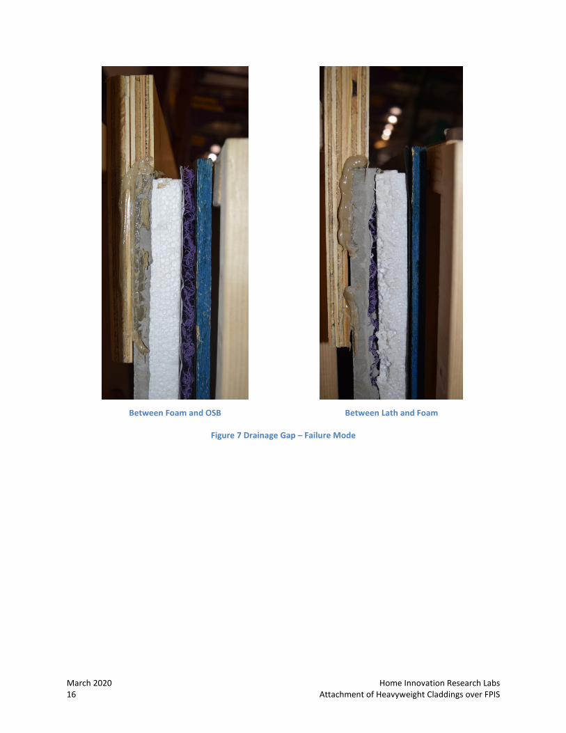
Between Foam and OSB Between Lath and Foam
Figure 7 Drainage Gap – Failure Mode

Home Innovation Research Labs March 2020 Attachment of Heavyweight Claddings over FPIS 17
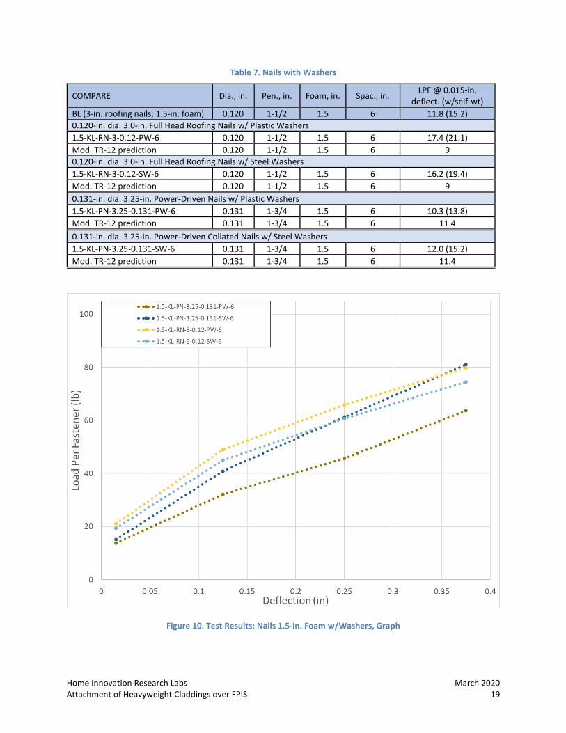
Table 7 and Figure 10 – 1.5-in. Foam w/Washers: Roofing nails (hand-driven) were compared to pneumatic nails with both plastic and steel washers. No credit is given in the NDS/TR-12 equations for the use of washers in wood connections, thus, the IRC and TR-12 predictions used for this study also do not make any adjustments to account for washer or fastener head effects. Note that the BL uses roofing nails, with a large, flat nail head which seats in the washer very snugly. The pneumatic nails used have smaller heads, and potentially could greatly benefit from the addition of a washer for this application since the reduced head size doesn’t properly engage with the wire of the lath.
• Adding a plastic washer to the BL 1.5-in foam specimen increased capacity from 15.2 lbs/fastener to 21.1 lbs/fastener (+38%)
• Adding a steel washer to the BL 1.5-in. foam specimen increased deflection-controlled capacity from 15.2 lbs/fastener to 19.4 lbs/fastener (+27.6%)
• Roofing nails with washers greatly outperformed the TR-12 predictions by about a factor of 2; with roofing nails, plastic washers performed slightly better than steel washers. This improvement for the 0.120-inch-diameter roofing nail (which was not observed for the 0.131-inch diameter pneumatic nail) may be related to greater head fixity provided by the washers relative to the bending strength of the 0.120-in diameter nail as compared to the 0.131-in diameter nail. The head size differences in these two nails also may play a role in the fixity that the washer is able to provide.
• The performance of the plastic versus the steel washer varied by the nail type; additional testing would be needed to confirm actual trends or differences.
• Pneumatic nails with plastic and steel washers were generally well-predicted by the IRC and modified TR-12 equation.
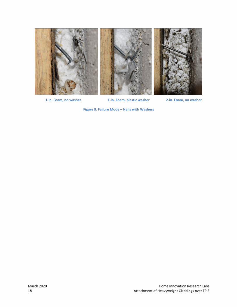
• The dissimilar performance effect of plastic or steel washers in combination with the 0.131-inch-diameter pneumatic nails tested seems to be due to the interaction of the nail head – smaller than that of a roofing nail – with the concave opening of the washers. The pneumatic nail head appears to seat less firmly than a roofing nail head, which appears to allow it to twist within the “collar” of the plastic washers, whereas the steel washer appears to adequately hold the pneumatic nail in position under load (Figure 8, Figure 10).
Figure 8. Nail Heads and Washers
March 2020 Home Innovation Research Labs 18 Attachment of Heavyweight Claddings over FPIS
1-in. Foam, no washer 1-in. Foam, plastic washer 2-in. Foam, no washer
Figure 9. Failure Mode – Nails with Washers
Home Innovation Research Labs March 2020 Attachment of Heavyweight Claddings over FPIS 19
Table 7. Nails with Washers
COMPARE Dia., in. Pen., in. Foam, in. Spac., in. LPF @ 0.015-in. deflect. (w/self-wt)
BL (3-in. roofing nails, 1.5-in. foam) 0.120 1-1/2 1.5 6 11.8 (15.2) 0.120-in. dia. 3.0-in. Full Head Roofing Nails w/ Plastic Washers 1.5-KL-RN-3-0.12-PW-6 0.120 1-1/2 1.5 6 17.4 (21.1) Mod. TR-12 prediction 0.120 1-1/2 1.5 6 9 0.120-in. dia. 3.0-in. Full Head Roofing Nails w/ Steel Washers 1.5-KL-RN-3-0.12-SW-6 0.120 1-1/2 1.5 6 16.2 (19.4) Mod. TR-12 prediction 0.120 1-1/2 1.5 6 9 0.131-in. dia. 3.25-in. Power-Driven Nails w/ Plastic Washers 1.5-KL-PN-3.25-0.131-PW-6 0.131 1-3/4 1.5 6 10.3 (13.8) Mod. TR-12 prediction 0.131 1-3/4 1.5 6 11.4 0.131-in. dia. 3.25-in. Power-Driven Collated Nails w/ Steel Washers 1.5-KL-PN-3.25-0.131-SW-6 0.131 1-3/4 1.5 6 12.0 (15.2) Mod. TR-12 prediction 0.131 1-3/4 1.5 6 11.4
Figure 10. Test Results: Nails 1.5-in. Foam w/Washers, Graph
March 2020 Home Innovation Research Labs 20 Attachment of Heavyweight Claddings over FPIS
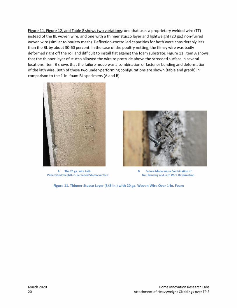
Figure 11, Figure 12, and Table 8 shows two variations: one that uses a proprietary welded wire (TT) instead of the BL woven wire, and one with a thinner stucco layer and lightweight (20 ga.) non-furred woven wire (similar to poultry mesh). Deflection-controlled capacities for both were considerably less than the BL by about 30-60 percent. In the case of the poultry netting, the flimsy wire was badly deformed right off the roll and difficult to install flat against the foam substrate. Figure 11, item A shows that the thinner layer of stucco allowed the wire to protrude above the screeded surface in several locations. Item B shows that the failure mode was a combination of fastener bending and deformation of the lath wire. Both of these two under-performing configurations are shown (table and graph) in comparison to the 1-in. foam BL specimens (A and B).
A. The 20 ga. wire Lath
Penetrated the 3/8-in. Screeded Stucco Surface
B. Failure Mode was a Combination of
Nail Bending and Lath Wire Deformation
Figure 11. Thinner Stucco Layer (3/8-in.) with 20 ga. Woven Wire Over 1-in. Foam

Home Innovation Research Labs March 2020 Attachment of Heavyweight Claddings over FPIS 21
Table 8. Lath and Stucco Variations vs BL, Results
COMPARE Dia., in. Pen., in. Foam, in. Spacing, in. LPF @ 0.015-in.
deflect. (w/self-wt) IRC basis calculation 0.120 1-1/4 1 8 11.3 Baseline A (17 ga. K-Lath. ½-in. stucco) 0.120 1-1/2 1 8 13.3 (17.8) Baseline B (17 ga. K-Lath. ½-in. stucco) 0.120 1-1/2 1 8 13.1 (17.7) 20 ga. Woven Wire, no furring and 3/8-in. stucco (~4.5 psf) 1-WW-RN-2.5-0.12-NW-8-3/8"Thick 0.120 1-3/4 1.0 8 8.6 (12.6) Mod. TR-12 prediction 0.120 1-3/4 1.0 8 11.1 17 ga. Welded Wire, self-furred with wire tracks to replace washers 1-TT-RN-2.5-0.12-NW-~5.5 0.120 1-3/8 1.0 ~5.5 10.6 (13.3) Mod. TR-12 prediction 0.120 1-3/8 1.0 ~5.5 13.1
Figure 12. Lath and Stucco Variations vs BL, Graph
March 2020 Home Innovation Research Labs 22 Attachment of Heavyweight Claddings over FPIS
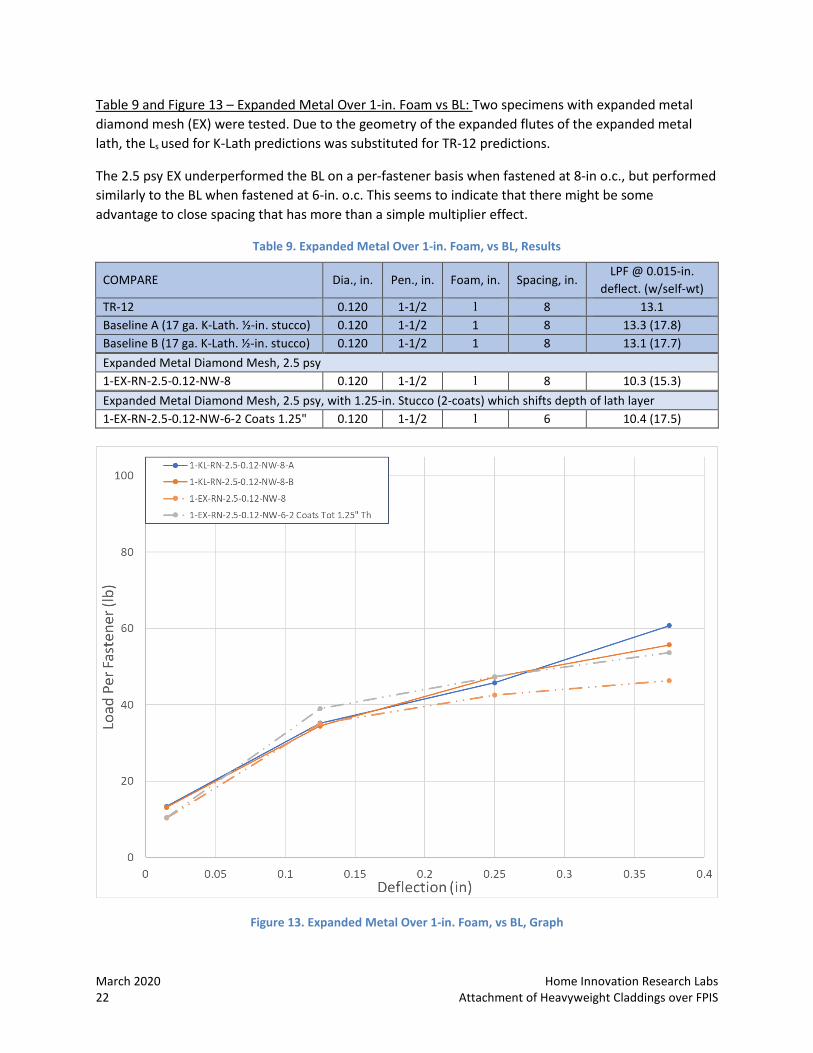
Table 9 and Figure 13 – Expanded Metal Over 1-in. Foam vs BL: Two specimens with expanded metal diamond mesh (EX) were tested. Due to the geometry of the expanded flutes of the expanded metal lath, the Ls used for K-Lath predictions was substituted for TR-12 predictions.
The 2.5 psy EX underperformed the BL on a per-fastener basis when fastened at 8-in o.c., but performed similarly to the BL when fastened at 6-in. o.c. This seems to indicate that there might be some advantage to close spacing that has more than a simple multiplier effect.
Table 9. Expanded Metal Over 1-in. Foam, vs BL, Results
COMPARE Dia., in. Pen., in. Foam, in. Spacing, in. LPF @ 0.015-in.
deflect. (w/self-wt) TR-12 0.120 1-1/2 1 8 13.1 Baseline A (17 ga. K-Lath. ½-in. stucco) 0.120 1-1/2 1 8 13.3 (17.8) Baseline B (17 ga. K-Lath. ½-in. stucco) 0.120 1-1/2 1 8 13.1 (17.7) Expanded Metal Diamond Mesh, 2.5 psy 1-EX-RN-2.5-0.12-NW-8 0.120 1-1/2 1 8 10.3 (15.3) Expanded Metal Diamond Mesh, 2.5 psy, with 1.25-in. Stucco (2-coats) which shifts depth of lath layer 1-EX-RN-2.5-0.12-NW-6-2 Coats 1.25" 0.120 1-1/2 1 6 10.4 (17.5)
Figure 13. Expanded Metal Over 1-in. Foam, vs BL, Graph

Home Innovation Research Labs March 2020 Attachment of Heavyweight Claddings over FPIS 23
Screws Screws are not listed in Table R703.15.1 Cladding Minimum Fastening Requirements for Direct Attachment over Foam Plastic Sheathing to Support Cladding Weight. Wood screws (#10) and lag screws (1/4") are included in Table R703.15.2 Furring Minimum Fastening Requirements for Application over Foam Plastic Sheathing to Support Cladding Weight, which is the reference included in Table 10, even though it is not directly related to this construction.
Figure 14. Table R703.15.2 from the IRC 2018 Section R703 Exterior Covering
The baseline set for screws includes 2-in foam using two different fastener schedules: one based on IRC Table R703.15.2 and a second one modified to the more typical spacing of 6-in. o.c., with a smaller-diameter screw. Screws are commonly specified for commercial installations of stucco over foam but are rare in residential application. The conical head of counter-sink screws requires washers to adequately capture strands of lath wire. Two of the test specimens used plastic washers and one used steel.
General Observations, Screws 1. Including a plastic washer, which added approximately 38% capacity in combination with a full-
head nail, appears to provide at least as much advantage when used with screws based on guidance of Figure 14.
2. Thinner screws (#8) at a more frequent fastening schedule in combination with plastic washers perform similarly on a per-fastener basis. This same configuration with steel washers adds an additional 50% capacity.

March 2020 Home Innovation Research Labs 24 Attachment of Heavyweight Claddings over FPIS
3. Stress at the collar of plastic washers (white discoloration) appears to occur as a result of the screw head beginning to pull through the washer under load. (Figure 15) A better match between washer and screw head may potentially provide better performance.
4. Use of the lath’s wire gauge in inches for modification of the TR-12 equation produces an under-prediction but does not take into account the additional strength attained by using a washer. Additional testing should be done to confirm and take advantage of this additional strength.
Table 10. Screws, Results
COMPARE Dia., in.
Pen., in.
Foam thick., in.
Spac., in.
Lbs/fastener @ 0.015-in. defl
#10 with Plastic Washer IRC (no washer) 0.190 1 2 12 From 3 to 11 2-KL-SC-3-#10-PW-12 0.190 1 2 12 12.8 (19.9) TR-12 (no washer) 0.190 1 2 12 8.4 #8 with Plastic Washer IRC (no washer) 0.160 1 2 6 NA 2-KL-SC-3-#8-PW-6 0.160 1 2 6 15.3 (19.0) TR-12 (no washer) 0.160 1 2 6 5.6 #8 with Steel Washer IRC (no washer) 0.160 1 2 6 NA 2-KL-SC-3-#8-SW-6 0.160 1 2 6 25.2 (28.5) TR-12 (no washer) 0.160 1 2 6 5.6
Figure 15. Screws with Plastic Washers – Failure Mode
Home Innovation Research Labs March 2020 Attachment of Heavyweight Claddings over FPIS 25
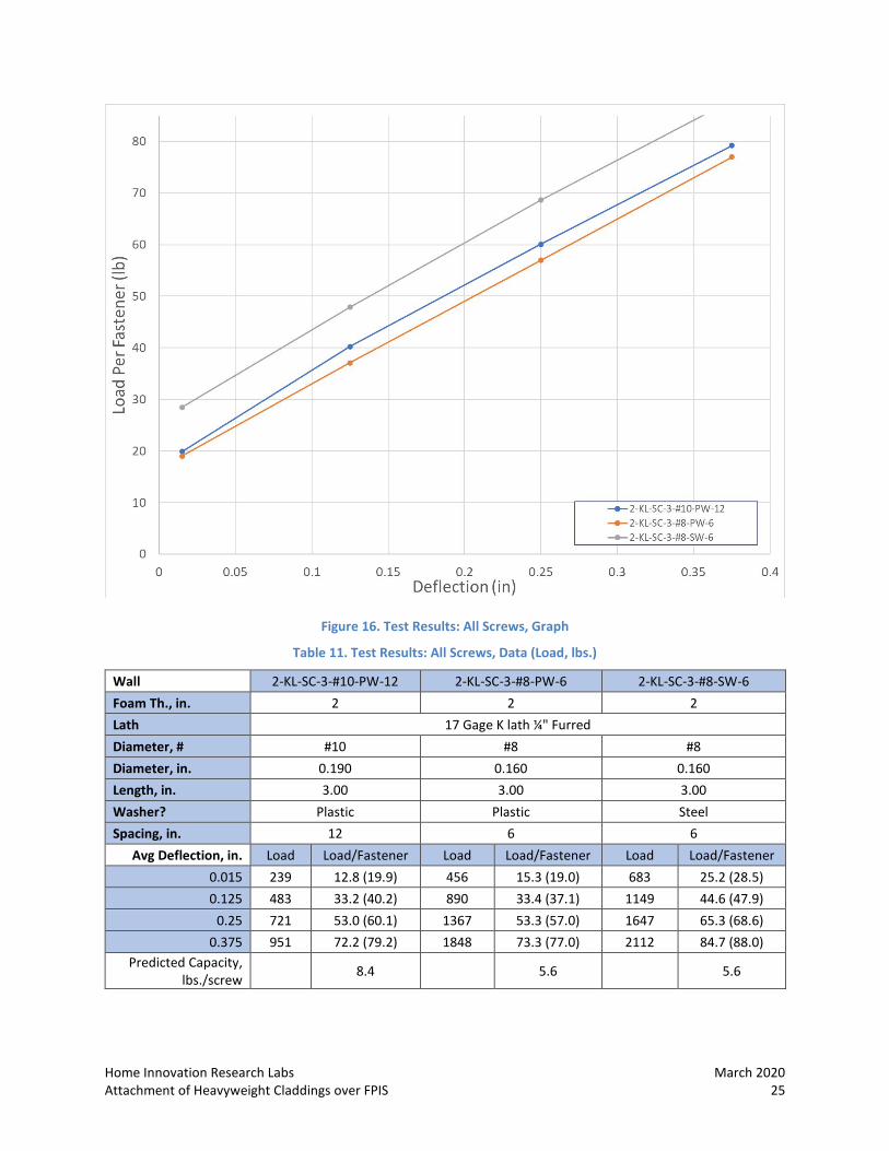
Figure 16. Test Results: All Screws, Graph
Table 11. Test Results: All Screws, Data (Load, lbs.)
Wall 2-KL-SC-3-#10-PW-12 2-KL-SC-3-#8-PW-6 2-KL-SC-3-#8-SW-6 Foam Th., in. 2 2 2 Lath 17 Gage K lath ¼" Furred Diameter, # #10 #8 #8 Diameter, in. 0.190 0.160 0.160 Length, in. 3.00 3.00 3.00 Washer? Plastic Plastic Steel Spacing, in. 12 6 6
Avg Deflection, in. Load Load/Fastener Load Load/Fastener Load Load/Fastener 0.015 239 12.8 (19.9) 456 15.3 (19.0) 683 25.2 (28.5) 0.125 483 33.2 (40.2) 890 33.4 (37.1) 1149 44.6 (47.9)
0.25 721 53.0 (60.1) 1367 53.3 (57.0) 1647 65.3 (68.6) 0.375 951 72.2 (79.2) 1848 73.3 (77.0) 2112 84.7 (88.0)
Predicted Capacity, lbs./screw 8.4 5.6 5.6

March 2020 Home Innovation Research Labs 26 Attachment of Heavyweight Claddings over FPIS
Staples Table 13 lists the characteristics of staples included in the research. Table 12 lists the staple characteristics compliant with ICC-ES Report ESR-1539 (Division: 06 00 00-Wood, Plastics and Composites Section: 06 05 23.13 – Nails) commissioned by the International Staple, Nail and Tool Association to evaluate power-driven staples and nails for various power-driven fastener manufacturers. The limited lengths, widths and gauges of readily available construction staples complicates the installation choices for the baseline set of walls.
Neither IRC 703 nor ASTM C1063 contain provisions for the use of staples with claddings installed over foam. One of the goals of this project was to test staples for this application, especially for heavyweight cementitious cladding. Some manufacturers of proprietary one-coat stucco products have developed guidance based on ICC-ES Evaluation Reports for use with stucco over 1-in. foam. The limited availability of long-leg staples in gauges of sufficient strength dictates maximum foam thickness, and the ¾-in. crown recommended by the ESRs is difficult to obtain. The first three specimens in the baseline set of Table 14 all use 1-in. foam and provide a comparison of staple gauge, crown width and framing penetration, in addition to confirming staples’ performance with stucco over 1-in. foam.
Table 12. Staples ESR-1539 (Available per Internet Search)
Table 13. Staple Characteristics
Manufacturer Gauge 2 in. L 2.25 in. L 2.5 in. L Crown, in., ≥ W., in. Th., in. Min. Pen. 12dPaslode yes no no 15/16 0.0625 0.055 0.75Bostitch yes no no 1 0.0625 0.055 0.75Senco yes no no 1 0.0625 0.055 0.75
Paslode yes no no 1/2 0.0625 0.055 0.75Bostitch yes no no 1/2 0.0625 0.055 0.75Senco yes no no 7/16 0.0625 0.055 0.75Senco 15 yes yes yes 7/16 0.0740 0.0670 0.888
16
16
1 or 2 1 or 2 1 or 2
B1ST1-1 B1ST2-1 B1ST3-1
Foam Thickness, in. 1 1 1
Type staple staple staple
Head / Crown, req'd 3/4-in. crown 3/4-in. crown 3/4-in. crown
Head / Crown, used 1-in. 7/16-in. 7/16-in.
Spacing req'd, in. 4 4 4
Diameter Req'd, in. 16 ga. 16 ga. 15 ga.
Penetration, in., req'd 1.25 1.25 1.25
Penetration, in., used 1 1 1.25
Length, in. (req'd) 2.25 2.25 2.25
Length, in. (used) 2 2 2.25
STAPLES
Fastener
BASELINE >>
Replicates >>
ID# >>

Home Innovation Research Labs March 2020 Attachment of Heavyweight Claddings over FPIS 27
Figure 17. Test Results: All Staples, Graph
General Observations, Staples (Figure 17)
1. Logical modification of staple length and gauge shows that staples may perform adequately even for foam thicknesses over 1-in.
2. Use of staples to attach stucco lath directly to sheathing without penetration to framing appears promising.
3. Something akin to a “community effect” seems to indicate that more numerous fasteners at spacing narrower than typical framing (16-in. o.c.) can shift the failure mode from a cascade of independent fastener bending to maximum lath capacity.
4. Staples with wider crowns appear to exhibit a secondary failure mode related to independent behavior of the two legs (Figure 19)
5. Use of the staple’s wire gauge in inches and the minimum bending moment from the table of values in ESR-1539 Table 3.2 Staple Characteristics for modification of the TR-12 produces a prediction within an order of magnitude of measured capacities.
Data tables and graphs in logical groupings for detailed comparison follow.
March 2020 Home Innovation Research Labs 28 Attachment of Heavyweight Claddings over FPIS
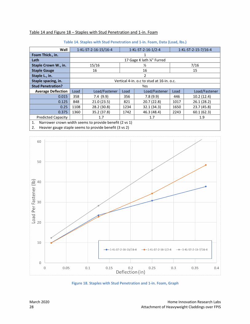
Table 14 and Figure 18 – Staples with Stud Penetration and 1-in. Foam
Table 14. Staples with Stud Penetration and 1-in. Foam, Data (Load, lbs.)
Wall 1-KL-ST-2-16-15/16-4 1-KL-ST-2-16-1/2-4 1-KL-ST-2-15-7/16-4 Foam Thick., in. 1 Lath 17 Gage K lath ¼" Furred Staple Crown W., in. 15/16 ½ 7/16 Staple Gauge 16 16 15 Staple L., in. 2 Staple spacing, in. Vertical 4-in. o.c to stud at 16-in. o.c. Stud Penetration? Yes
Average Deflection Load Load/Fastener Load Load/Fastener Load Load/Fastener 0.015 358 7.4 (9.9) 356 7.8 (9.9) 446 10.2 (12.4) 0.125 848 21.0 (23.5) 821 20.7 (22.8) 1017 26.1 (28.2)
0.25 1108 28.2 (30.8) 1234 32.1 (34.3) 1650 23.7 (45.8) 0.375 1360 35.2 (37.8) 1742 46.3 (48.4) 2243 60.1 (62.3)
Predicted Capacity 1.7 1.7 1.9 1. Narrower crown width seems to provide benefit (2 vs 1) 2. Heavier gauge staple seems to provide benefit (3 vs 2)
Figure 18. Staples with Stud Penetration and 1-in. Foam, Graph

Home Innovation Research Labs March 2020 Attachment of Heavyweight Claddings over FPIS 29
Figure 19. Staples with Different Crown Widths – Failure Modes
March 2020 Home Innovation Research Labs 30 Attachment of Heavyweight Claddings over FPIS
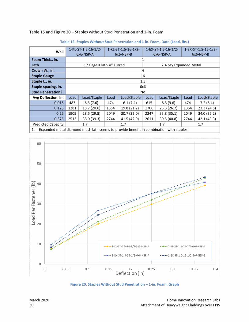
Table 15 and Figure 20 – Staples without Stud Penetration and 1-in. Foam
Table 15. Staples Without Stud Penetration and 1-in. Foam, Data (Load, lbs.)
Wall 1-KL-ST-1.5-16-1/2-6x6-NSP-A
1-KL-ST-1.5-16-1/2-6x6-NSP-B
1-EX-ST-1.5-16-1/2-6x6-NSP-A
1-EX-ST-1.5-16-1/2-6x6-NSP-B
Foam Thick., in. 1 Lath 17 Gage K lath ¼" Furred 2.4 psy Expanded Metal Crown W., in. ½ Staple Gauge 16 Staple L., in. 1.5 Staple spacing, in. 6x6 Stud Penetration? No Avg Deflection, in. Load Load/Staple Load Load/Staple Load Load/Staple Load Load/Staple
0.015 483 6.3 (7.6) 474 6.1 (7.4) 615 8.3 (9.6) 474 7.2 (8.4) 0.125 1281 18.7 (20.0) 1354 19.8 (21.2) 1706 25.3 (26.7) 1354 23.3 (24.5)
0.25 1909 28.5 (29.8) 2049 30.7 (32.0) 2247 33.8 (35.1) 2049 34.0 (35.2) 0.375 2513 38.0 (39.3) 2744 41.5 (42.9) 2611 39.5 (40.8) 2744 42.1 (43.3)
Predicted Capacity 1.7 1.7 1.7 1.7 1. Expanded metal diamond mesh lath seems to provide benefit in combination with staples
Figure 20. Staples Without Stud Penetration – 1-in. Foam, Graph
Home Innovation Research Labs March 2020 Attachment of Heavyweight Claddings over FPIS 31
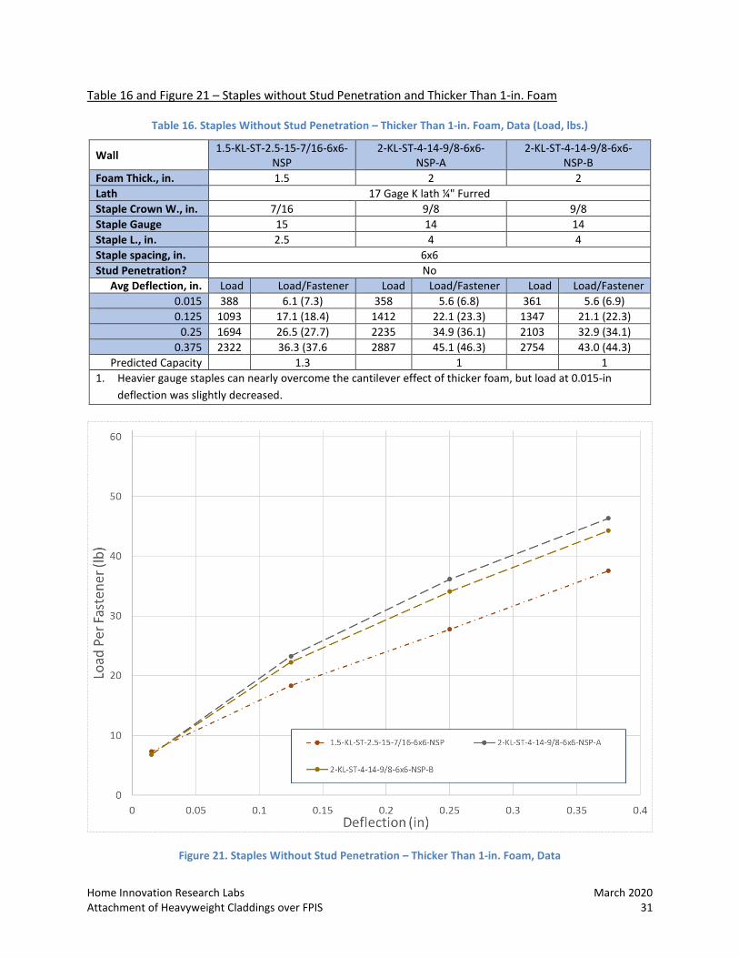
Table 16 and Figure 21 – Staples without Stud Penetration and Thicker Than 1-in. Foam
Table 16. Staples Without Stud Penetration – Thicker Than 1-in. Foam, Data (Load, lbs.)
Wall 1.5-KL-ST-2.5-15-7/16-6x6-NSP
2-KL-ST-4-14-9/8-6x6- NSP-A
2-KL-ST-4-14-9/8-6x6- NSP-B
Foam Thick., in. 1.5 2 2 Lath 17 Gage K lath ¼" Furred Staple Crown W., in. 7/16 9/8 9/8 Staple Gauge 15 14 14 Staple L., in. 2.5 4 4 Staple spacing, in. 6x6 Stud Penetration? No
Avg Deflection, in. Load Load/Fastener Load Load/Fastener Load Load/Fastener 0.015 388 6.1 (7.3) 358 5.6 (6.8) 361 5.6 (6.9) 0.125 1093 17.1 (18.4) 1412 22.1 (23.3) 1347 21.1 (22.3)
0.25 1694 26.5 (27.7) 2235 34.9 (36.1) 2103 32.9 (34.1) 0.375 2322 36.3 (37.6 2887 45.1 (46.3) 2754 43.0 (44.3)
Predicted Capacity 1.3 1 1 1. Heavier gauge staples can nearly overcome the cantilever effect of thicker foam, but load at 0.015-in
deflection was slightly decreased.
Figure 21. Staples Without Stud Penetration – Thicker Than 1-in. Foam, Data
March 2020 Home Innovation Research Labs 32 Attachment of Heavyweight Claddings over FPIS
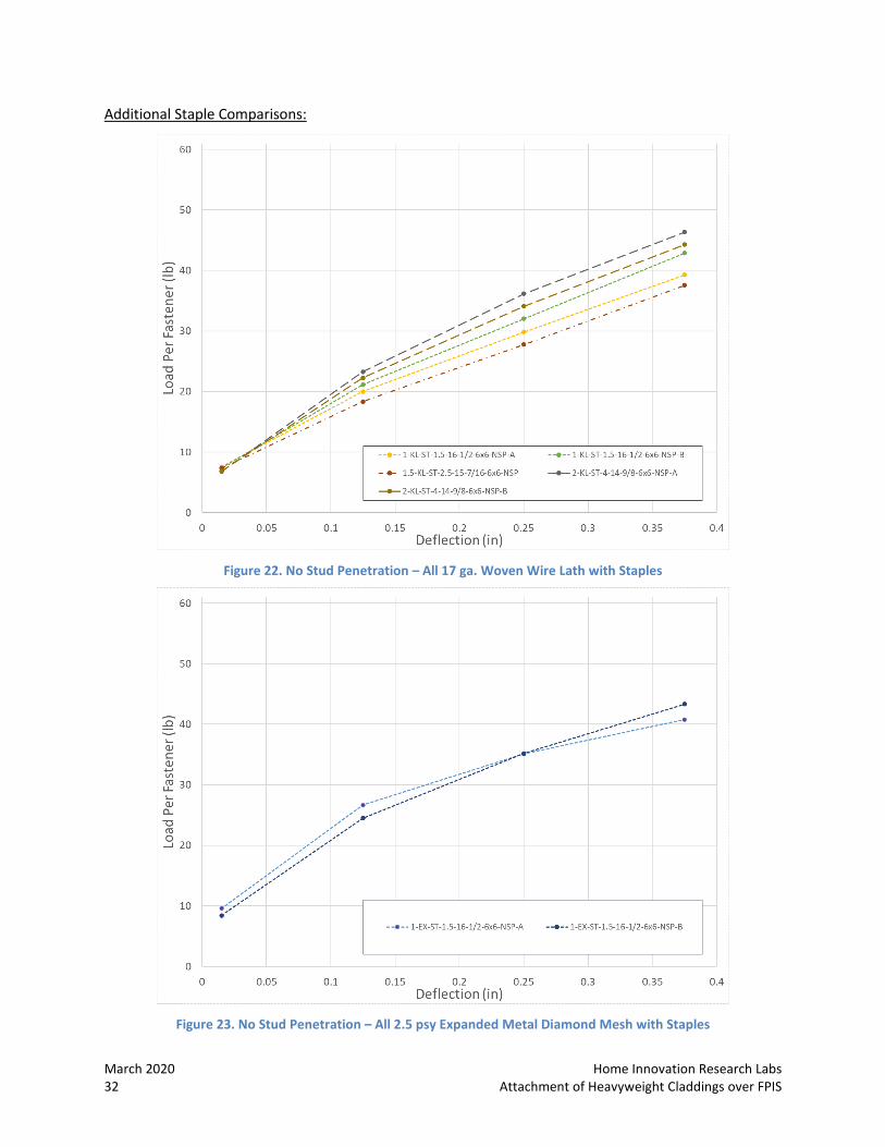
Additional Staple Comparisons:
Figure 22. No Stud Penetration – All 17 ga. Woven Wire Lath with Staples
Figure 23. No Stud Penetration – All 2.5 psy Expanded Metal Diamond Mesh with Staples
Home Innovation Research Labs March 2020 Attachment of Heavyweight Claddings over FPIS 33
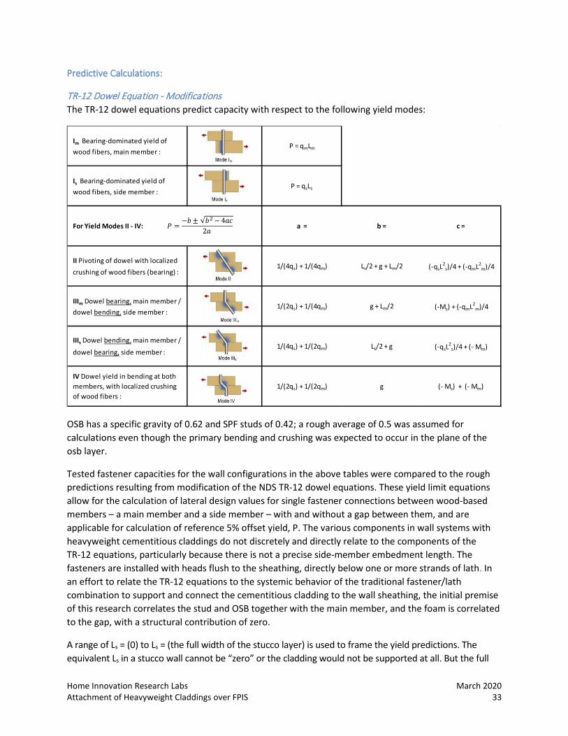
Predictive Calculations:
TR-12 Dowel Equation - Modifications The TR-12 dowel equations predict capacity with respect to the following yield modes:
OSB has a specific gravity of 0.62 and SPF studs of 0.42; a rough average of 0.5 was assumed for calculations even though the primary bending and crushing was expected to occur in the plane of the osb layer.
Tested fastener capacities for the wall configurations in the above tables were compared to the rough predictions resulting from modification of the NDS TR-12 dowel equations. These yield limit equations allow for the calculation of lateral design values for single fastener connections between wood-based members – a main member and a side member – with and without a gap between them, and are applicable for calculation of reference 5% offset yield, P. The various components in wall systems with heavyweight cementitious claddings do not discretely and directly relate to the components of the TR-12 equations, particularly because there is not a precise side-member embedment length. The fasteners are installed with heads flush to the sheathing, directly below one or more strands of lath. In an effort to relate the TR-12 equations to the systemic behavior of the traditional fastener/lath combination to support and connect the cementitious cladding to the wall sheathing, the initial premise of this research correlates the stud and OSB together with the main member, and the foam is correlated to the gap, with a structural contribution of zero.
A range of Ls = (0) to Ls = (the full width of the stucco layer) is used to frame the yield predictions. The equivalent Ls in a stucco wall cannot be “zero” or the cladding would not be supported at all. But the full
1/(4qs) + 1/(2qm) Ls/2 + g (-qsL2
s)/4 + (- Mm)
1/(2qs) + 1/(2qm) g (- Ms) + (- Mm)
1/(4qs) + 1/(4qm) Ls/2 + g + Lm/2 (-qsL2
s)/4 + (-qmL2m)/4
1/(2qs) + 1/(4qm) g + Lm/2 (-Ms) + (-qmL2m)/4
II Pivoting of dowel with localized crushing of wood fibers (bearing) :
IIIm Dowel bearing, main member / dowel bending, side member :
IIIs Dowel bending, main member /
dowel bearing, side member :
IV Dowel yield in bending at both members, with localized crushing of wood fibers :
For Yield Modes II - IV: a = b = c =
Im Bearing-dominated yield of wood fibers, main member :
P = qmLm
Is Bearing-dominated yield of wood fibers, side member :
P = qsLs
𝑃 =−𝑏± 𝑏2− 4𝑎𝑐
2𝑎
March 2020 Home Innovation Research Labs 34 Attachment of Heavyweight Claddings over FPIS
thickness of the cladding is also not likely to represent the Ls component. The metal lath is the connective tissue of the stucco wall, and during application of the wet stucco this ribbing is held off the substrate (the foam CI, in this case) approximately ¼-in. by furring, so that the stucco material may be fully keyed-in and embedded. This furring “stand-off” is often an integral, shaped dimension incorporated in the lath manufacturing process. Figure 40 illustrates three types of such “self-furred” lath.
For this study, the TR-12 dowel equation adjusts the parameter Ls (embedment depth of the faster into the side member) to be the thickness of the lath gauge, in inches, and the characteristics of the chosen fastener are used for the dowel diameter and bearing moment. Test results were used to modify these assumptions; identifying the relationship between the factor Ls and the actual wall performance is vital. For staples the TR-12 dowel equation uses the fastener characteristics from ICC-ES Report ESR-1539 for the dowel diameter and bearing moment. For all of these equations, it seems likely a factor modifier could be developed to accurately predict performance for design purposes.
Phase II: Aging and Weathering Select specimens duplicating certain test configurations are being exposed to actual weather conditions on the campus of HI’s research lab to establish the long-term reliability of the attachment method with respect to duration of loading under varying temperature and moisture conditions. Cracking and other abnormalities were observed and documented.
Methodology
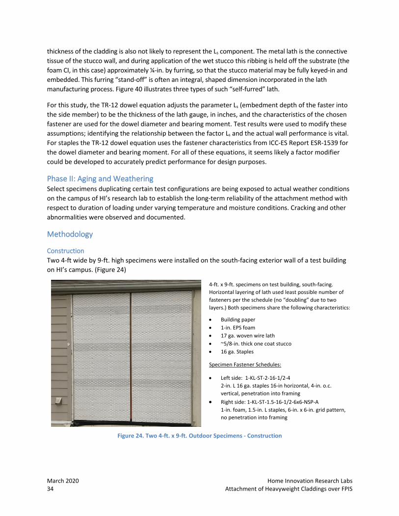
Construction Two 4-ft wide by 9-ft. high specimens were installed on the south-facing exterior wall of a test building on HI’s campus. (Figure 24)
4-ft. x 9-ft. specimens on test building, south-facing. Horizontal layering of lath used least possible number of fasteners per the schedule (no “doubling” due to two layers.) Both specimens share the following characteristics:
• Building paper • 1-in. EPS foam • 17 ga. woven wire lath • ~5/8-in. thick one coat stucco • 16 ga. Staples
Specimen Fastener Schedules:
• Left side: 1-KL-ST-2-16-1/2-4 2-in. L 16 ga. staples 16-in horizontal, 4-in. o.c. vertical, penetration into framing
• Right side: 1-KL-ST-1.5-16-1/2-6x6-NSP-A 1-in. foam, 1.5-in. L staples, 6-in. x 6-in. grid pattern, no penetration into framing
Figure 24. Two 4-ft. x 9-ft. Outdoor Specimens - Construction
Home Innovation Research Labs March 2020 Attachment of Heavyweight Claddings over FPIS 35
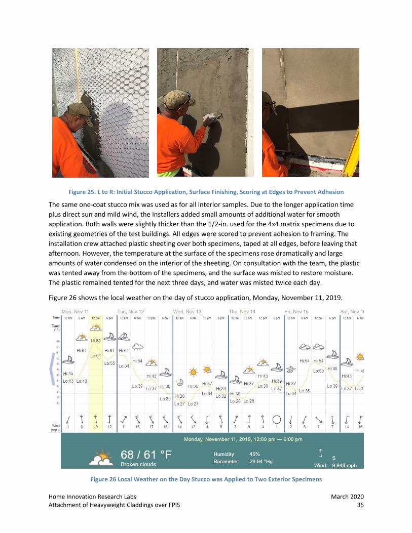
Figure 25. L to R: Initial Stucco Application, Surface Finishing, Scoring at Edges to Prevent Adhesion
The same one-coat stucco mix was used as for all interior samples. Due to the longer application time plus direct sun and mild wind, the installers added small amounts of additional water for smooth application. Both walls were slightly thicker than the 1/2-in. used for the 4x4 matrix specimens due to existing geometries of the test buildings. All edges were scored to prevent adhesion to framing. The installation crew attached plastic sheeting over both specimens, taped at all edges, before leaving that afternoon. However, the temperature at the surface of the specimens rose dramatically and large amounts of water condensed on the interior of the sheeting. On consultation with the team, the plastic was tented away from the bottom of the specimens, and the surface was misted to restore moisture. The plastic remained tented for the next three days, and water was misted twice each day.
Figure 26 shows the local weather on the day of stucco application, Monday, November 11, 2019.
Figure 26 Local Weather on the Day Stucco was Applied to Two Exterior Specimens
March 2020 Home Innovation Research Labs 36 Attachment of Heavyweight Claddings over FPIS
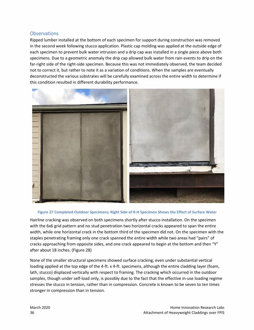
Observations Ripped lumber installed at the bottom of each specimen for support during construction was removed in the second week following stucco application. Plastic cap molding was applied at the outside edge of each specimen to prevent bulk water intrusion and a drip cap was installed in a single piece above both specimens. Due to a geometric anomaly the drip cap allowed bulk water from rain events to drip on the far-right side of the right-side specimen. Because this was not immediately observed, the team decided not to correct it, but rather to note it as a variation of conditions. When the samples are eventually deconstructed the various substrates will be carefully examined across the entire width to determine if this condition resulted in different durability performance.
Figure 27 Completed Outdoor Specimens; Right Side of R-H Specimen Shows the Effect of Surface Water
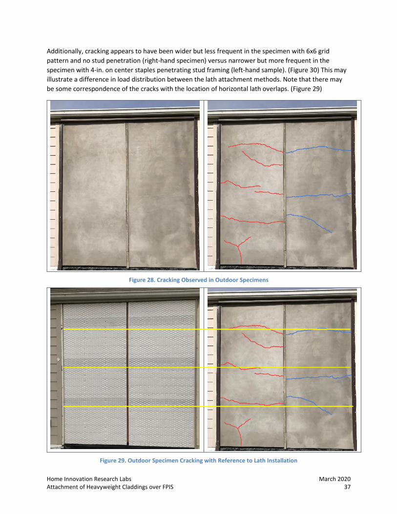
Hairline cracking was observed on both specimens shortly after stucco installation. On the specimen with the 6x6 grid pattern and no stud penetration two horizontal cracks appeared to span the entire width, while one horizontal crack in the bottom third of the specimen did not. On the specimen with the staples penetrating framing only one crack spanned the entire width while two areas had “pairs” of cracks approaching from opposite sides, and one crack appeared to begin at the bottom and then “Y” after about 18 inches. (Figure 28)
None of the smaller structural specimens showed surface cracking, even under substantial vertical loading applied at the top edge of the 4-ft. x 4-ft. specimens, although the entire cladding layer (foam, lath, stucco) displaced vertically with respect to framing. The cracking which occurred in the outdoor samples, though under self-load only, is possibly due to the fact that the effective in-use loading regime stresses the stucco in tension, rather than in compression. Concrete is known to be seven to ten times stronger in compression than in tension.
Home Innovation Research Labs March 2020 Attachment of Heavyweight Claddings over FPIS 37
Additionally, cracking appears to have been wider but less frequent in the specimen with 6x6 grid pattern and no stud penetration (right-hand specimen) versus narrower but more frequent in the specimen with 4-in. on center staples penetrating stud framing (left-hand sample). (Figure 30) This may illustrate a difference in load distribution between the lath attachment methods. Note that there may be some correspondence of the cracks with the location of horizontal lath overlaps. (Figure 29)
Figure 28. Cracking Observed in Outdoor Specimens
Figure 29. Outdoor Specimen Cracking with Reference to Lath Installation

March 2020 Home Innovation Research Labs 38 Attachment of Heavyweight Claddings over FPIS
Above: 4-in. on center staples penetrating stud framing, upper set of cracks
Above: 6x6 grid pattern with no stud penetration, upper set of cracks
Above: 4-in. on center staples penetrating stud framing, lower set of cracks
Above: 6x6 grid pattern with no stud penetration, lower set of cracks
Figure 30. Close Ups of Cracks, Outdoor Samples
Home Innovation Research Labs March 2020 Attachment of Heavyweight Claddings over FPIS 39
RECOMMENDATIONS Potentially useful future research includes:
• Further exploration of shorter fasteners, especially staples. Wider use of staples for installation of cementitious claddings over foam may substantially increase speed and reduce cost.
o Confirm the evident “community effect” that appears to increase the per fastener capacity as a result of increased frequency. (Staples) This may allow development of a staple schedule using closer spacing and no framing penetration.
o Validate the apparent effect of wider staple crowns introductin an intermediate failure mode by allowing slippage along the length of the crown, potentially resulting in a recommendation of narrower crowns.
o Durability tests with staple penetrations of OSB to wall cavity. Gauge and leg lengths for site-applied staples are limited – it may be necessary to use longer leg lengths for this application, which will penetrate the sheathing through to the stud cavity. Durability testing could confirm that a new installation approach which results in frequent small punctures to the wall cavity does not introduce new risks. Since direct attachment to sheathing without framing penetrations is already acceptable for lightweight claddings under IRC Table R703.3.3 OPTIONAL SIDING ATTACHMENT SCHEDULE FOR FASTENERS WHERE NO STUD PENETRATION NECESSARY this topic may be of wider interest.
• Exploration of additional combinations of power-driven nail and screw head types with washers, or modification of the geometry of one or both, to optimize the support contributed by the washer and to improve installation speed and cost. A calibrated means to predict performance would be necessary for design and code development purposes. (Nails, Screws) Explore and improve the relationship between the shape and size of the nail head and the washer’s material and contours (the shape of the “collar” or neck of the washer where the nail head seats).
• Additional specimen configurations of drainage gap (DG) types, thickness and locations to further confirm the effect of the drainage gap on structural performance. (Nails)
o Potentially develop a test method to understand the actual effect of a gap that is not filled with foam. Precursor research (1980’s dowel equation theory and testing by Forest Products Lab) used layers of foam to replicate a void, but this project’s results indicate that added resistance by foam may affect performance, possibly by stiffening the joint. Results from this research for specimens with nails indicated that the drainage gap – achieved with a relatively pliable woven plastic filament mat – affected fastener capacity differently depending on whether the DG was installed between the lath and the foam layer (stronger – small reduction vs no DG) versus between the foam layer and the sheathing (weaker – larger reduction vs no DG). Drainage gaps with a range of materials and varying density of rigid foam board would aid this confirmation and future guidance.
• More fully test alternate fastener approaches in real-world conditions; potentially devise a method to apply loads exceeding self-load in tension, rather than compression.
o Additional aspects of performance or appearance may warrant research. Third-party examination of specimens larger than 4x4 exposed to weather conditions including extremes of ambient temperature, moisture and direct solar radiation may be informative to industry. (Phase II: Aging and Weathering)
• Consider testing higher density rigid foam boards to determine whether capacity is affected

March 2020 Home Innovation Research Labs 40 Attachment of Heavyweight Claddings over FPIS
Page Intentionally left Blank
Home Innovation Research Labs March 2020 Attachment of Heavyweight Claddings over FPIS 41
APPENDIX
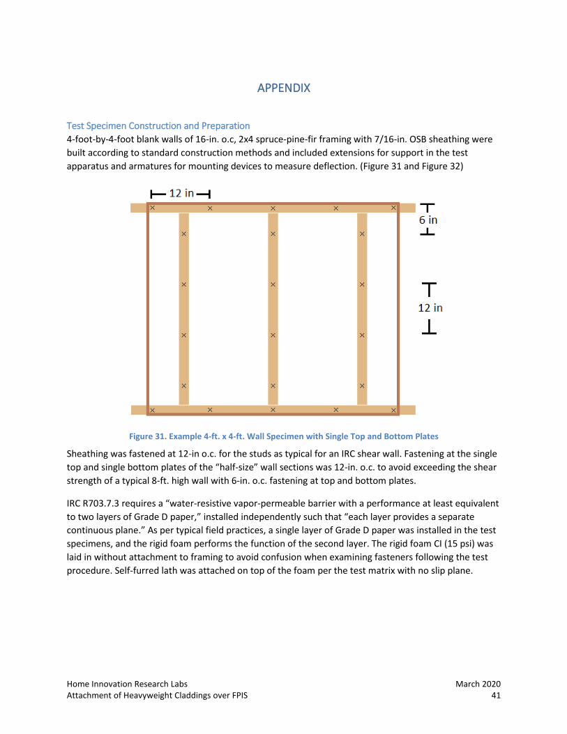
Test Specimen Construction and Preparation 4-foot-by-4-foot blank walls of 16-in. o.c, 2x4 spruce-pine-fir framing with 7/16-in. OSB sheathing were built according to standard construction methods and included extensions for support in the test apparatus and armatures for mounting devices to measure deflection. (Figure 31 and Figure 32)
Figure 31. Example 4-ft. x 4-ft. Wall Specimen with Single Top and Bottom Plates
Sheathing was fastened at 12-in o.c. for the studs as typical for an IRC shear wall. Fastening at the single top and single bottom plates of the “half-size” wall sections was 12-in. o.c. to avoid exceeding the shear strength of a typical 8-ft. high wall with 6-in. o.c. fastening at top and bottom plates.
IRC R703.7.3 requires a “water-resistive vapor-permeable barrier with a performance at least equivalent to two layers of Grade D paper,” installed independently such that “each layer provides a separate continuous plane.” As per typical field practices, a single layer of Grade D paper was installed in the test specimens, and the rigid foam performs the function of the second layer. The rigid foam CI (15 psi) was laid in without attachment to framing to avoid confusion when examining fasteners following the test procedure. Self-furred lath was attached on top of the foam per the test matrix with no slip plane.

March 2020 Home Innovation Research Labs 42 Attachment of Heavyweight Claddings over FPIS
Figure 32. Example 4-ft. x 4-ft. Wall Specimen with Rigid Foam and Lath
A perpendicular “picture frame” of scrap OSB was built around each specimen to ensure square, orthogonal, uniform edges and were labeled with the number of each specimen for photo documentation. This helped achieve the target thickness for each cladding weight category (typically ½-in.). One-coat stucco was applied in one or two layers, depending on the target thickness and weight. Completed stucco claddings were periodically misted in the first 48 hours. All specimen walls cured for a minimum of 28 days total. Proprietary, sanded one-coat stucco mix was used for all walls to ensure consistency; water was measured for each batch, and the amount was varied only if ambient relative humidity varied from typical. The “picture frame” was removed prior to testing.
Blank test walls were photographed and weighed prior to applying the WRB, foam and lath, and again prior to applying the stucco. Completed, cured specimen walls with stucco cladding were weighed within 24 hours prior to testing to determine total cladding system weight (csw) and stucco cladding weight.
Lumber used for framing was pre-qualified for appropriate specific gravity (SG +/- 10% of 0.42) by weighing and measuring. Samples were collected and tested per ASTM D2395 Test Methods for Density and Specific Gravity (Relative Density) of Wood and Wood-Based Materials. Two-in. cube samples of each batch of stucco were tested for density and strength. Bending yield tests were performed in the lab on samples of each nail type used per ASTM F1575.
Each wall was built in a vertical position in indoor, climate-controlled conditions. Specimens were cured, stored and transported in the vertical position. Specimens were stored indoors for the duration of the project, both prior to and following testing, until completion of the project.
Home Innovation Research Labs March 2020 Attachment of Heavyweight Claddings over FPIS 43
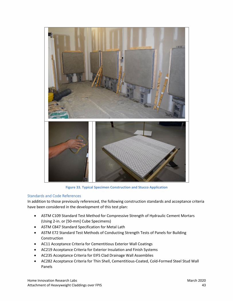
Figure 33. Typical Specimen Construction and Stucco Application
Standards and Code References In addition to those previously referenced, the following construction standards and acceptance criteria have been considered in the development of this test plan:
• ASTM C109 Standard Test Method for Compressive Strength of Hydraulic Cement Mortars (Using 2-in. or [50-mm] Cube Specimens)
• ASTM C847 Standard Specification for Metal Lath • ASTM E72 Standard Test Methods of Conducting Strength Tests of Panels for Building
Construction • AC11 Acceptance Criteria for Cementitious Exterior Wall Coatings • AC219 Acceptance Criteria for Exterior Insulation and Finish Systems • AC235 Acceptance Criteria for EIFS Clad Drainage Wall Assemblies • AC282 Acceptance Criteria for Thin Shell, Cementitious-Coated, Cold-Formed Steel Stud Wall
Panels
March 2020 Home Innovation Research Labs 44 Attachment of Heavyweight Claddings over FPIS
• ASTM D1761 Standard Test Methods for Mechanical Fasteners in Wood • ASTM F1575 Standard Test Method for Determining Bending Yield Moment of Nails • ASTM F1667 Standard Specification for Driven Fasteners: Nails, Spikes, and Staples
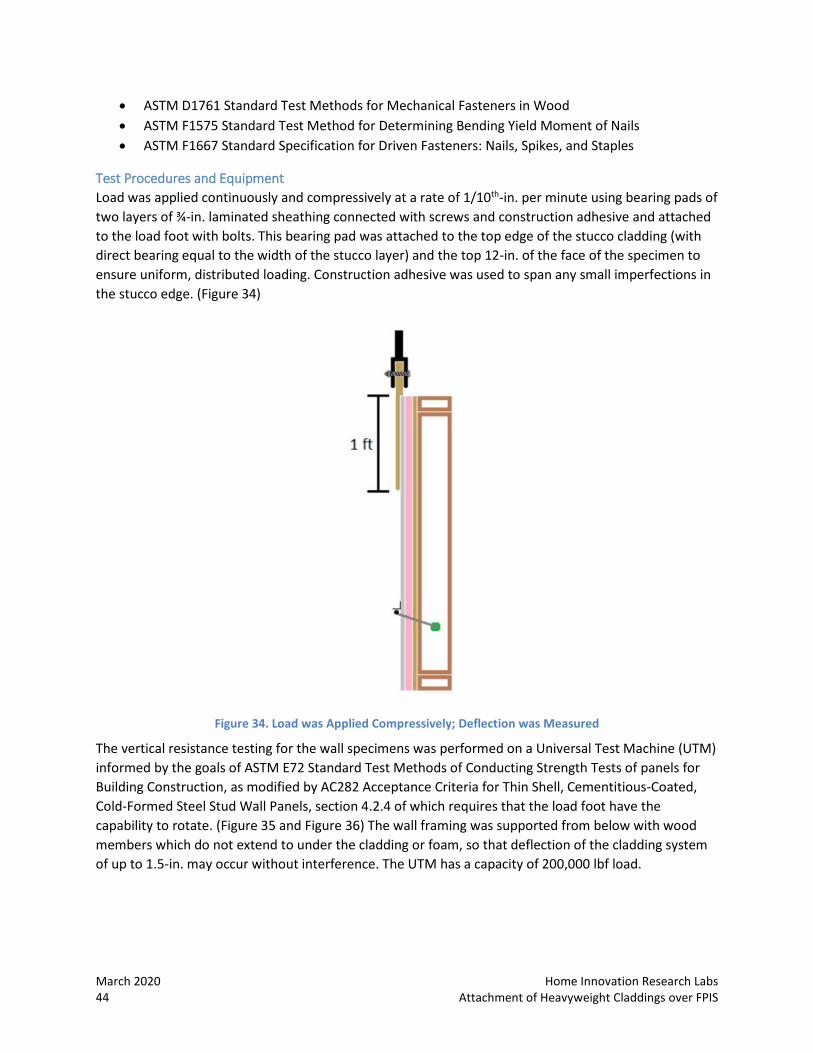
Test Procedures and Equipment Load was applied continuously and compressively at a rate of 1/10th-in. per minute using bearing pads of two layers of ¾-in. laminated sheathing connected with screws and construction adhesive and attached to the load foot with bolts. This bearing pad was attached to the top edge of the stucco cladding (with direct bearing equal to the width of the stucco layer) and the top 12-in. of the face of the specimen to ensure uniform, distributed loading. Construction adhesive was used to span any small imperfections in the stucco edge. (Figure 34)
Figure 34. Load was Applied Compressively; Deflection was Measured
The vertical resistance testing for the wall specimens was performed on a Universal Test Machine (UTM) informed by the goals of ASTM E72 Standard Test Methods of Conducting Strength Tests of panels for Building Construction, as modified by AC282 Acceptance Criteria for Thin Shell, Cementitious-Coated, Cold-Formed Steel Stud Wall Panels, section 4.2.4 of which requires that the load foot have the capability to rotate. (Figure 35 and Figure 36) The wall framing was supported from below with wood members which do not extend to under the cladding or foam, so that deflection of the cladding system of up to 1.5-in. may occur without interference. The UTM has a capacity of 200,000 lbf load.

Home Innovation Research Labs March 2020 Attachment of Heavyweight Claddings over FPIS 45
Figure 35. UTM with 4-ft x 4-ft Wall Specimen
Figure 36. UTM with Rotation Foot
Two deflectometers were used for vertical resistance testing, installed one on each side of the test specimen, to measure deflection of the cladding with respect to the framing; loads at the following deflections are included in the results: 0.015-in., 0.125-in., 0.250-in., 0.375-in. A dial indicator measured the movement of the osb sheathing relative to the framing. Movement as compared to framing for all specimens was inconsequential, and not reported. (Figure 37) The data acquisition system for the UTM was used to control the rate of loading and record test data. (Figure 38) The rate of loading was 100 lbs./min, or no faster than 1/10th -in. deflection per minute. Load was applied to each specimen until one of three conditions is met:
1. a deflection of 1-in. is reached at both sides of the specimen 2. the average deflection at both sides of the specimen reaches 1-in. 3. in each case, the test was run past a proof load (PL) of 5 times the cladding system weight (CSW)

March 2020 Home Innovation Research Labs 46 Attachment of Heavyweight Claddings over FPIS
Figure 37. Deflectometer
Figure 38. UTM Data Acquisition System
Test Plan Failure of the wall system was measured/observed in the following ways:
1. Deflection of cladding with respect to framing – recorded and reported in test results 2. Deflection of sheathing with respect to framing; typically, this movement was ≤ 7/1,000 of an
inch at the end of the test under full load and was not reported 3. Cracking – none observed as a result of test loads 4. Any other physical or visual deformation – none observed as a result of test loads
Test results included:
1. Test ID and all specimen construction details, including foam thickness 2. CSW – cementitious cladding system weight, and resulting psf. This value was determined by
subtracting the frame weight from the final test specimen weight (cladding/foam/lath/framing weight) to determine the cladding system weight
3. The approximate density of the specimen cladding. This value was roughly determined at the time of each test by measuring and weighing 2-inch cubes of each stucco batch, cured in the same conditions as each specimen wall
4. Deflection at maximum load for each deflectometer 5. Load vs. displacement, in graphical form 6. Tabular results: load (lbs) per specimen and per fastener at the following deflections: 0.015-in.,
0.125-in., 0.250-in., 0.375-in. 7. Failure mode(s) 8. Cracking or other surface deformities as visually identified and reported via photographs and
tabular or narrative descriptions including appearance, location, length, direction, and gap size.
Home Innovation Research Labs March 2020 Attachment of Heavyweight Claddings over FPIS 47
Specimen Materials The development matrix includes several proprietary and generic stucco material and accessories. Table 1 and Table 2 in the preceding report detail specifics of specimen construction.
Stucco: A single, specific one-coat stucco mix was used to ensure consistency. Quikcrete is available nationwide, and often sold at home improvement stores. All stucco was applied in a single coat and batches of two bags were used for pairs of 4-ft. x 4-ft. specimens. Each specimen had a plywood frame offset at ½-in. to aid the stucco installer in meeting the target thickness. Enough was left from each batch to make three 2-in. cube samples for later strength testing and to provide material for infill of imperfections during finishing after initial cure of 30-minutes to 1-hr.
Fasteners: Nails, screws and staples were used to match existing guidance as closely as possible or to logically extend a concept resulting from notable test results. See results sections for fastener details.
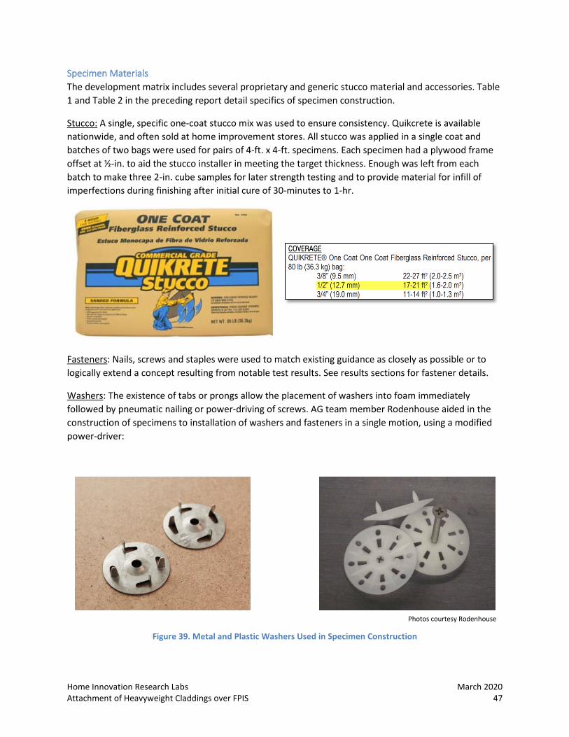
Washers: The existence of tabs or prongs allow the placement of washers into foam immediately followed by pneumatic nailing or power-driving of screws. AG team member Rodenhouse aided in the construction of specimens to installation of washers and fasteners in a single motion, using a modified power-driver:
Photos courtesy Rodenhouse
Figure 39. Metal and Plastic Washers Used in Specimen Construction

March 2020 Home Innovation Research Labs 48 Attachment of Heavyweight Claddings over FPIS
Lath: 17 ga. welded wire with ¼-in. self-furring was used in baseline configurations, as a conservative but common solution. Industry Advisory Group (AG) discussions indicated that expanded metal lath is common in the south and the mid-Atlantic corridor. Self-furred welded wire is entering all markets but is less common. (Figure 40)
Photos courtesy Structa Wire Corp.
Figure 40. Self-Furred Woven, Expanded, and Welded Metal Lath (from left)
Drainage Gaps: Woven plastic filament mats were chosen as the most conservative method of testing a two different drainage gap sizes, since this material is unlikely to provide much structural support. Drainage gaps were included in two different locations – both between the foam and the building paper and between the foam and the stucco layer. A commercial matt which included a scrim was used to ensure no integration of the stucco material with the foam in the second location.
Figure 41. Woven Plastic Filament Drainage Mats Used in Specimen Construction – L: 1/4-in.; R: 3/8-in.