attachment 3- (continued) · 02/02/1975 · table 3-2 redundancy management definition redundancy...
TRANSCRIPT

ATTACHMENT 3- 2 (Continued)
Delays in Receiving and Tes t ing SSME Components
What is the na ture of t h e s e p rob lems? t e s t p r o g r a m ?
What is thc impact on the NSTL
Answer:
T h e SSME P r o j e c t i s experiencing delays in the manufac ture of h a r d w a r e s i m i l a r t o tha t exper ienced on previous engine development p r o g r a m s . T h e de lays a r e indicat ive of the complexity of thc va r ious manufactur ing p r o c e s s e s involved and the devcloprnent l ea rn ing cycle. IIowever, a t th i s t i m e approximate ly t h r e e spec imens have been m a d e of a l l h a r d w a r e i t e m s , except fo r the 77: l nozzle scheduled for complet ion in e a r l y CY76. T h e ini t ia l spec imen exper ience and the hardening of thc tooling continually improves the h a r d w a r e schedule visibil i ty. The tes t ing o l
components and the engine s y s t e m i s not being dr iven by the h a r d w a r c schedules and adequate h a r d w a r e ex i s t s to p e r f o r m the t e s t s a s thc test fac i l i t i es and engineer ing planning allow.
53

ATTACHMENT 3- 2 (Continued)
SSME Cont ro l l e r
When do you expect to have the n e c e s s a r y information on the p rob lems with the c u r r e n t Cont ro l le r to m a k e a decis ion on the backup unit? What kinds of in format ion will be cons idered?
Answer :
T h e t e s t exper ience with the f i r s t prototypc con t ro l l e r (PP- 1 ) and the ISTB expe r i ence with the r a c k mounted cont ro l le r ( E M - 1 ) and i t s sof tware , have el iminated t h e need for f u r t h e r backup con t ro l l c r planning. While s o m e changes a r e being cons idered t o r educe sensc l ine noise and t o r educe fabr ica t ion p rob lems with the M a s t e r I n t e r - connect B o a r d (MIB) , cons iderable exper ience h a s been accumulated through functional and envi ronmenta l t e s t s of PP-1 and through the ISTB t e s t s conducted t o date a t NSTL. While long durat ion tes t ing at environmental e x t r e m e s is s t i l l to b e completed over the next few months , the functional and s h o r t t e s t durat ion t h c r m a l and vibra t ion da ta accumula ted to date ind ica tes that the p r e s e n t con t ro l l e r can b e m a d e t o function within the engine p r o g r a m cons t ra in ts . C losu re of t h e backup con t ro l l e r contingency planning effort i s p re sen t ly bcing staffed between Level 11 and Level 1.
(The November 1974 Contingency P l a n for SSME Cont ro l le r identified a t a r g e t date of e a r l y July 1975 fo r making a decis ion on this subject based on pro jec tcd availabil i ty of tes t ing cxper icncc and p rocurcmcn t lead t i m c s . A t thc t i m e of our review with t h c P a n e l , late A p r i l , thc t e s t and manufac tur ing cxpc r i encc accumii la tcd with 1’1’- 1 indicatcd tha t backup con t ro l l e r effort would not be requi red . )
54

TABLE 3-1
FACTORS OF SAFETY FOR SSME
AT FULL POWER LEVEL VS. RATED POWER LEVEL
F a c t o r O f S a f e t y (Calcul ,ed) SSME HARDWARE ITEM FPL RPL
Low
Low
Pressure Oxid ize r Turbopump Housing Inducer Turb ine Blades Turb ine S t a t o r Vanes S h a f t
P r e s s u r e F u e l Turbopump Turbine Housing Pump Housing Inducer S h a f t
High P r e s s u r e Ox id ize r Turbopump Second S tage Turbine Blades F i r s t s t a g e Turbine Disc F i r s t s t a g e Turbine Nozzle Turb ine bel lows Turbine F a i r i n g Turbine Ex ha u s t S t r u t s Turbine I n l e t Housing Pump Ho us ing- I n 1 e t
D i s c h a r ge D i f f u s e r Vanes
Preburner Volu te Main S h a f t
1.50 1.50 4.40 1 .42 1.69
2 . 1 2 1 .53 2.74 1.91
1.76 1 .48 2.27 1.69 2.28 1.50 1.65 1.62 1.62 1 .41 1.59 1.50
High P r e s s u r e Fue l Turbopump Second S tage Turbine Blades 1.40 Second S tage Turbine Disks 1.40 F i r s t S t age Turbine Nozzle 1 .83 Second S tage Turbine Nozzle 1 .55 Turbine Bellows 1 .53 Turbine Bearing Thermal S h i e l d 1.76 Turbine Bearing Support 2.66 S h a f t System 1.46 Pump Hous ing-Mount ’ g f l a n g e 1.50
Discharge 1.82 D i f f u s e r Vanes 2 . 1 2
Th i rd S tage Impel le r 1 .79 F i r s t S t age D i f f u s e r s 1.50
Pump I n l e t vanes 2.00
1.67 1.67 4.90 1.58 1.69
2.29 1 .64 2.90 2.02
2.03 1 . 7 1 2.50 1.97 2.67 1.75 1.93 1.89 1.70 1.50 1.70 1.75
1.49 1.49 1.96 1.66 1.64 1.89 2.86 1.53 1 .61 1.94 2.26 2.20 1.91 1 .61
55

TABLE 3-1 (cont inued)
PPL RPL Valve Ac tua to r s
Connection Flange 1.40 1.40 P r e s s u r e Cy l inde r s 2.00 2.00
Gimbal Bearing Body S h a f t S e a t
1.48 1.57 1.64 1.64 1.47 1.47
Hot G a s Manifold S h e l l 1.42 I n j e c t o r W e Id 2.08 Fue l Preburner Weld 1.55 Ox id ize r Preburner Weld 1.45 Fuel-Side C o l l e c t o r L ine r 9.- Fue l=Side T r a n s f e r Tube L i n e r s 1 .75 Oxid-Side C o l l e c t o r L i n e r 2.90 Oxid-Side Trans. Tube L ine r s 4.22 Heat Exchanger Weld 2.70
1 .56 2.29 1.70 1.59 9.- 1 .75 2.90 4 .22 3.00
Main Combustion Chamber Ac tua to r S t r u t s 1.41 1 .41 I n l e t Man i f o Id 1.41 1.48 Discharge Manifold 1.47 1.55 Long i tud ina l Welds 1.40 1.50 Liner - E l e c t r o Deposi t N i 1.60 1.79 - Narloy-Z 2.29 2.54 Acous t ic Cavi ty 2.61 2.83
56

TABLE 3-2
REDUNDANCY MANAGEMENT DEFINITION
REDUNDANCY - REFERS TO HOW OFTEN A FUNCTION IS REPLICATED
0 REDUNDANCY MANAGEMENT - REFERS TO HOW MONITOR I NG & CONTROL OF REDUNDANT FUNCTIONS ARE PERFORMED
e , FAIL OPERATIONAL (FO) - MISSION OBJECTIVES CAN BE ACCOMPLISHED AFTER A SINGLE FAILURE
v, @, FAIL SAFE (FS) -J
0 FO/FS
FDI
- SAFE VEHICLE & CREW RECOVERY AFTER S I N G U FAILURE
- FO AFTER FIRST FAILURE &THEN FS FOR ANY SUB- SEQUENT FAILURE WITHIN THE SAME SUB- SYSTEM
ANNUNC I ATION) - FAULT DETECTION & IDENTIFICATION (AND
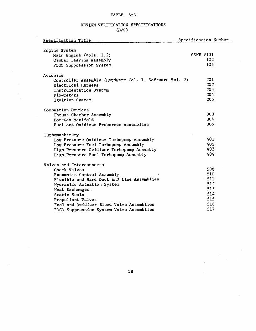
TABLE 3-3
DESIGN VERIFICATION SPECIFICATIONS (DV s )
Specification Title Specification Number
Engine Sys tem Main Engine (Vols. 1,2) SSME /I101 Gimbal Bearing Assembly POGO Suppression System
Avionics Controller Assembly (Hardware Vol. 1, Software Vol. 2 ) Electrical Harness Instrumentation System Flowmeter s Ignition Sys tem
Combustion Devices Thrust Chamber Assembly Hot-Gas Manifold Fuel and Oxidizer Preburrier Assemblies
T urbomac h ine r y Low Pressure Oxidizer Turbopump Assembly Low Pressure Fuel Turbopump Assembly High Pressure Oxidizer Turbopump Assembly High Pressure Fuel Turbopump Assembly
Valves and Interconnects Check Valves Pneumatic Control Assembly Flexible and Hard Duct and Line Assemblies Hydraulic Actuation System Heat Exchanger Static Seals Propellant Valves Fuel and Oxidizer Bleed Valve Assemblies POGO Suppression System Valve Assemblies
10 2 10 6
20 1 20 2 20 3 204 205
303 304 305
4 0 1 40 2 40 3 404
508 510 511 512 513 5 14 515 516 5 17
58

AS I
OPB & FPB
TCA
4CK
NOZZLE
BEAT EX,
TABLE 3-4
COMBUSTION DEVICES - TESTING SUMMARY (THROUGH APRIL 1976)
TESTS COMPLETED
28 TO FPL 700 ENG, START
19 TO FPL
17 TO FPL
102 CYCLES RPL (MCC)
17 TO FPL (35:l)
TESTS PLANNED TO CDR
FULL DURATION 4 TESTS
ZND UNIT PERF, 8 DURABILITY (MAX, COND I T IONS 1 STAB I L I TY
32 TESTS
BOMB DEVELOPMENT (PHASE B TCA)
STAB I L ITY 8, DURAB I L I TY (MAX, CONDITIONS)
ZND UNIT PERF, 8 DURABILITY (MAX, CONDITIONS)
5 TESTS
11 TESTS
10 TESTS
40 ADD'L CYCLES ON INJECTOR 28 TESTS
77,5:1 FPL OPERATION (MAXI CONDITIONS) 3 i i S T S
10 TESTS -IlP
PERF, , DURABILITY 8 FLOW STABILITY

FIGURE 3-1
ENGINEERING
CHIEF PROGRAM ENGINEER
ASSOCIATE PROGRAM MANAGERS
ENGINE SYSTEMS, CONTROLS & GSE
BUSINESS MANAGEMENT
DIRECTOR
TU RBOM ACH IN E RY
MANUFACTURING
DIRECTOR
-
COMBUSTION DEVICES
INTEGRATED SYSTEMS TEST BED (ISTB)
VICE PRESIDENT AND PROGRAM MANAGER I
QUALITY. RELIABILITY &SYSTEMSAFETY
DIRECTOR
SPACE SHUTTLE MAIN ENGINE PROGRAM
ORBITER INTEGRATION
FACILITIES
DIRECTOR

FIGURE 3-2
Q\ P-
PROGRAM MANAGER
r
ASSOCIATE PROGRAM MANAGERS
ENGINE SYSTEMS, CONTROLS & GSE
TURBOMACHINERY
COMBUSTION OEVICES
ENGINE CONTROLLER
:OMPONENT & ENGINE 002 HARDVIARE
3
MANUFACTURING
DIRECTOR
MATERIAL OUALITY. RELIABILITY & SYSTEM SAFETY
DIRECTOR DIRECTOR
-- x
SPACE SHUTTLE MAIN ENGINE PROGRAM
I I I ENGINEERING TEST FACILITIES
CHIEF PROGRAM ENGINEER DIRECTOR DIRECTOR
ASSISTANT CHIEF PROGRAM ENGINEER
-% 7
1 NATIONAL SPACE
BUSINESS MANAGEMENT TECHNOLOGY LAB SSME RESIDENT MANAGER
AND ENGINE TEST OIRECTOR

ET V E N T V A L V E S 0.
VENT VALVES
LH2 VENT
POINT
LOA01 G E V S F R
4
PO I NT SENSORS
LOAD)
POINT SENSORS (ENC C / O )
ORBITER -t>
OISCONNCCT
FIGURE 3-3
MAIN PROPULSION SUBSYSTEM SCHEMATIC (FLUID)
LO2 TK HELIUM PRE PRESS
SHUTOFF VALVE
RELIEF VALVE
\ PRESSURANT I f\ EbON:ROL
VALVE ARRESTOR VALVE
VALVE L EILL r P ' VE
GND SY s
02 BLEEO OISCONNECT ' IWlRELlEF VALVE1
~ LW2 TI( MELlUY CRE CRESS.
0 FROM PVEUMAT I C SUPPLY
LH2 F I L L DISCONNECT
LO2 F I L L DISCONNECT

V
c-(
/ /
/ 1
I
/ /
/ /
/ /
w E5 zl H
I II
1 I
0
0
0
0
0
0
I
d
cu u3
V
W
v, I
w x
I- Y
0L.X Sal - lSntlH
l E-
63

4.0 ORBITER THERMAL PROTECTION SUBSYSTEM
4.1 Introduction
The Orbiter 101 Critical Design Review and the Orbiter 102 Preliminary
Design Reviews have resulted in a reasonably firm baseline of the
Orbiter Thermal Protection Subsystem (TPS). A s a result, detailed
drawing releases, fabrication of hardware, detailed tests, have all
begun. The Panel reviewed both the management systems and their
implementation as well as the technical adequacy cf the TPS. Given
this new technology, the Panel wants to assure an adequate basis of
confidence in reliability of the TPS and therefore crew safety.
The Panel has had this critical Shuttle hardware system under
review during the past two years as shown in Table 4.1. The Orbiter
TPS is, of course, a many-faceted system of the Orbiter. It is affected
by many factors: aerodynamic pressures; structural deflections on the
Orbiter; and the External Tank and Solid Rocket Booster elements of
the Shuttle Cluster. Given this complexity it was apparent that the
Panel could not provide detailed scrutiny of all these aspects. There-
fore the Panel and the Task Team focused on (a) the technical require-
ments for the TPS during phases of the Shuttle mission, @) those
features of the TPS most affected by unique mission requirements,
operational restrictions, resource reductions, (c) challenges created
in using new technology, and (d) flight test requirements not pre-
viously experienced on manned space flights.
64

I
The Panel examined the management systems in terms of its 11-
herant capability for handling (a) communications between technical
personnel and through senior levels of management, @) the hazards
identified and their resolution and risk assessment, (c) such major
technical problems and interface effects as design, test, fabrication,
logistics, maintenance, and assembly. Technical areas covered in
these discussions covered materials and processes, thermal analyses,
structural adequacy, systems integration, TPS and Orbiter hardware
properties affectbd by aerothermodynamics of ascent and reentry.
Many parts of the program impacting the TPS are under review by
the Task Teams for such areas as the Shuttle Major Ground Test Pro-
gram, Approach and Landing Test Program, the Orbital Flight Test
Program, Development Flight Instrumentation, External Tank and Solid
Rocket Booster Programs, and Risk Assessment.
The fact-finding began with detailed preliminary data collection
and analysis resulting in a discussion with appropriate program
personnel to establish the specific areas of interest, the personnel
that should be involved and the best sites for the discussions. Then
the team undertook on-site reviews with various levels of working and
management personnel and examined as appropriate the hardware/sof tware,
tests, and documentation.
The team then reviewed the program response to their action item
65

and subsequent baseline reviews and test results. This report is
based on such activities.
4.2 Observations
4.2.1 Organization
There have been no measureable changes in the management organ-
ization of personnel since the Panel's last report to the Administrator
dated June 1975. Based on discussions with NASA and contractor per-
sonnel the organization appears to be operating well and is producing
the necessary communication between all levels.
visibility of the overall status of the TPS program.
continue to review the ability of the various TPS organizational
Top management has
The Panel will
elements to respond quickly.to changing program needs when they are
defined at the Orbiter 102 Critical Design Review and as a result of
the updated "loads programs. "
4.2.2 Review System
The Orbiter Thermal Protection Subsystem Design Review conducted
from mid-July through mid-August 1975 was an extension of the Orbiter
102 Preliminary Design Review (PDR). Since this is a good example
of the depth and scope of such a review, the following particulars
on the process are cited:
July 28th Data Packages after having been checked and assembled were sent to

July 28 - August 8
August 12-13
August 14
participants for critique at the following locations: JSC, KSC, ARC, LaRC, NASA Headquarters, SAMSO.
The data was reviewed and Review Item Dispositions (RID' S) were sub- mitted as a result of this critique.
The Screening Group reviewed all RID'S, resolved the technical or management questions where appropriate and identi- fied those items to be brought before the full, formal Review Board.
The TPS Formal Review Board reviewed the actions of the screening group, resolved the issues which required their management authority and assigned the actions to be taken in ensuing months.
The distribution of RID'S across the TPS technical areas is indicative
of where the remaining challenges were found;
Structures (reuseable Carbon-Carbon leading edge, reuse- Surface Insulation-Tiles and Nomex, Thermal Con- trol Subsystem-Internal, Stress/Loads, Materials/Pro- cesses)
Development Flight Instrumentation and Avionics
Aero Sciences
Systems Integration
Test Program
Reliability/Safety
Quality Assurance
Manufacturing
The risk management system for the Orbiter TPS was also reviewed.
67

The system is continuing t o produce hazard assessments. For example,
the NASA document "Space Shut t le Safety Concerns Summary Report," JSC
09990, dated December 15, 1975 covers the following:
a. Damage to the Orbiter TPS from the i ce shed from the
External Tank.
b. Possible impact of the External Tank and Orb i t e r a f t e r
i n i t i a l separation.
c. Damage to the Orbiter by the motor plume from Solid
Rocket Booster a f t e r separation.
Based on the mater ia l presented to the Panel and the discussions
between Pane1 members and NASA and contractor personnel i t appears
tha t the review system a s applied to the Orbiter TPS i s working
reasonably w e l l a t a l l levels .
4.2.3 Documentation
The Panel se lec t ive ly r,eviews TPS re la ted documents covering
the various aspects of the design, t e s t , and fabricat ion of the
Orbiter TPS. Table 4-2 i s a p a r t i a l l i s t i n g of the documentation
reviewed by the Panel since i t s l a s t report to the Administrator.
4.2.4 Design Progress
Since the basic Orbiter TPS has been described i n both p r io r
Panel documents and many NASA and contractor program documents, i t
68

i s assumed t h a t the reader i s acquainted with the TPS subsyste. o r
has access t o the material noted above. Observations a s presented
here cover several areas: (a) s i g n i f i c a n t changes to data reported
i n the Panel's las t Annual Report to the Administrator, (b) new in-
formation developed during Panel reviews and task team a c t i v i t i e s ,
and (c) observations of other Panel Task Teams t h a t r e l a t e t o the
developing bas is of confidence i n the Orbiter TPS' a b i l i t y to support
a successful Orbi ta l mission.
4.2.4.1 Mass Properties
The new F e l t Reuseable Surface Insulat ion (FRSI) replaces a por-
t i o n of the low temperature t i l es (LRSI). This change reduces the
TPS accountable weight by some 300 pounds. A descr ipt ion of t h i s
newest addi t ion t o the TPS i s provided i n Paragraph 4.2.4.3. However,
there a r e a number of items tha t a r e expected t o lead t o weight increases.
These items include d e f i n i t i o n of the penetrations and closeout, beef-
up of the reinforced carbon-carbon panel, the outer moldline fa i r ing ,
the high pressure gradient flow b a r r i e r , the aero-surface s e a l require-
ments, LRSI coating thickness and o p t i c a l property change.
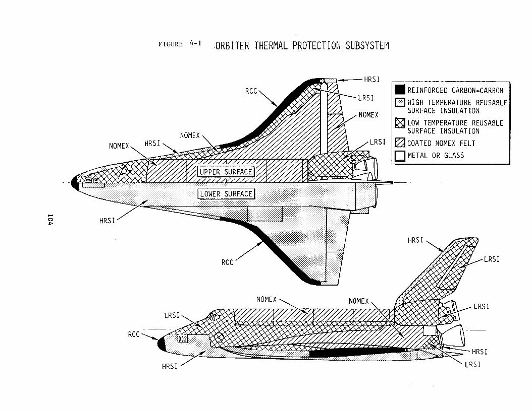
4.2.4.2 TPS Material Distr ibut ion
The d i s t r i b u t i o n and configuration of the f ive ( 5 ) d i f f e r e n t
types of TPS materials used to cover the Orbiter surface a r e as
69

shown in Figure 4-1.
4 . 2 . 4 . 3 Felt Reuseable Surface Insulation (FRSI)
Studies conducted in the last months of 1974 showed that the
minimum gage LRSI tiles overprotected the structure in many areas.
The temperature of the structure in these areas was below 350' F.
so that it might be possible to have a "bare top surface."
was, however, considered an unacceptable risk for the first orbital
flight. The concentrated test and analysis program covered many
materials and material systems and finally selected the Nomex felt.
Therefore, the LRSI tiles covering areas with surface temperatures
of - L 700° F during entry and at 750°F or less during ascent have been re-
placed w i t h DC92-007 silicon paint coating on Nomex felt. There is a con-
tinuing effort to extend the use of this coated Nomex material to
further reduce weight and complexity of the TPS.
cern in changing from tile to Nomex was that there might be a "flutter"
interaction. Therefore, a two-foot by four-foot specimen is presently
being tested at the Ames Research Center to determine the "flutter"
characteristics of this assembly.
This
The only major con-
Table 4-4 describes the FRSI material.
4.2.4.4 Orbiter 101
There is a concern regarding the simulated tiles on the Orbiter
101 for the Approach and Landing Test program vehicle. These are
70

made of polyurethane foam covered with Hypalon coating. The ccncern
is with the foam material and its compatibility with various Orbiter
fluids, e.g., hydraulic fluid, APU propellants, etc. There is a
potential fire hazard due to this incompatibility. NASA and the
Orbiter contractor are examining this area and expect to have a
resolution available shortly.
4.2.4.5 TPS Issues
At the time of the Panel's review the following technical chal-
lenges were being worked so each is discussed in the following para-
graphs :
a. HRSI and LRSI tile coatings.
b. Unique shaped tile
c. Tile-to-tile steps
d. Airframe panel buckling
e. Static door thermal barriers
f. High pressure gradient barriers
g. Use of densified fused silica
h. Use of minimum thickness LRSI tile
i. Body flap, rudder speed brake, elevon aerothermal seals
4.2.4.5.1 Tile Coatings and Unique Shaped Tiles
There is an intensive and detailed materials development program
7 1

for the tile coating. The program has been conducted by NASA at the
Ames Research Center, Johnson Space Center, Rockwe11 Internationat,
and the Lockheed Missile and Space Company. In trying to meet the
RSI tile coating goals, the program has been having problems with
cracks in the coating on the sidewalls of the High Temperature Re-
useable Surface Insulation. The Low Temperature tiles (LRSI) coating
is still undergoing demonstration tests on the mechanical adequacy
and characterization of its material properties.
The goals for the RSI coating are to:
a. Minimize devitrification during thermal exposure.
b. Minimize thermal expansion coefficient (about 3 x 10 -7
in./in./OF).
c. Minimize morphological (form and structure) changes
during thermal exposure.
d. Maintain imperviousness to water. e. Optimize optical properties3 €20.8, HRSIg=l.O, *c LEI2'0.4
f. Meet dimensional tolerance requirements.
g. Provide as much as possible resistance to ground handling
and impact damage.
Based on the latest information available to the Panel the pro-
gram has an approach to resolving the tile coating problem. The pre-
sent coating (identified as #0050) consists of silicon carbide and
72

cobalt oxide emissivity agents. The basecoat is slip cast fuse.1 silica
with a basic borosilicate glass as the coating. The test program to
resolve the #=0050 coating problems involves Lockheed, Rockwe11, Ames
and JSC support during the first portion of 1976. At the same time
there is a program to evaluate the reaction cured glass coating pro-
cess developed by b e s Research Center. The so-called reaction cured
glass coatings are produced by blending the components, then affixing
them by spray or paint on the substrate and finally heating the coated
tile rapidly to the reaction temperature for the reciprocal action of
the ingredients on each other. The result is a three-layered coating
with an outer layer of Boron Oxide rich glass, a center layer of Boro-
silicate glass + Tetraboron Silicide, and an inner layer against the tile of borosilicate glass. When the tests and analyses are com-
pleted it is expected that a final decision on the coating material
will be made in mid-1976.
In addition to the effort to produce un-flawed coatings, Rockwell
International is evaluating the impact of flaws on mission performance.
This seems worthwhile since the coating cracking problem appears to
be applicable to the LRSI as well as the H R S I ; the tiles are subject
to damage by any impact, human or natural; and there is presently no
viable test method of detecting the sidewall flaws.
For the total TPS tile program, NASA approved material character-
73

ization plan specifies that:
"The mechanical properties, as described under test
programs are divided into three catagories to prevent
unnecessary and redundant testing.
Category 1: The approach is to test enough specimens
in one or more critical properties to verify gaussian
distribution in a population 9f specimens taken from
multiple batches of material that has not been well
characterized previously. Where similar materials
have been well characterized or where generous mar-
gins are predicted, fewer test specimens are re-
quired. A demonstration of a 1.5 safety margin, us-
ing material properties degraded by 100 mission thermal
history, will satisfy any requirements for further
testing of that property.
Category 2:
scheduled in Category 1, some unsatisfactory margins
may result. In these cases, Category 1 results will
be assessed, and additional testing will be performed.
In addition, certain tests will be conducted when in-
formation is required but does not result in a design
allowable. Category 2 tests cannot be completely de-
With only a minimum number of data points
74

fined until Category 1 testing is complete.
Category 3: After satisfactory allowables are generated,
other conditions that could affect the useful life of
the TPS wiil be evaluated.
defined but include evaluation of the effect of natural
environments, working fluids, temperature overshoot,
permeability, and waterproofness. 'I
These are not yet completely
Only Category 1 tests are defined in the current issue of the
test document RI SD74-SH-0156.
4.2.4.5.2 Tile-To-Tile Steps
To assure an undisturbed airflow over the Orbiter tile surfaces
the program must assure that the height of adjacent tiles be held
within very tight limits. Figure 4-2 shows the 10-mil "forward step"
criteria which is an installation problem covering about 17% of the
TPS area. Other areas may permit a somewhat greater step difference
as shown, i.e., 30-mil forward and 50-mil backward steps in non-critical
aerothenno-dynamic areas.
4.2.4.5.3 Airframe Panel Buckling
The problem with possible cracking of thin tiles as a result of
structural deflections was noted in the Panel's last annual report.
Currently this could be a problem in Some 1800 square feet
cf surface compared to an original estimate of a little more
75

200 square feet. Therefore, it is an issue which contipues to re-
ceive attention. The program is considering such proposed solutions
as use of softer strain isolator pad (SIP), smaller tiles, strength-
ening of the structure, and the reduction in thin tile area by using
Nomex (FRSI). Trade-off studies indicate at this time that the most
cost-effective solution is to revise the structure rather than modify
the TPS with the exception of using FRSI.
4.2.4.5.4 High Pressure Gradient Barriers
There are a number of locations, comprising fairly large surface
areas, where there are high to low pressure gradients along the tile
gaps resulting in increased gap heating and possibly flow-tripping.
Such regions where such connections between high and low pressure
flow can exist include chines and trailing edges in particular. The
problem is to preclude the flow of gas through the gaps with barriers
of some type. The manner in which these flow stoppers could be manu-
factured and installed are still under study.
4.2.4.5.5. Use of Minimum Thickness RSI Tile
This area of concern has been discussed in the previous sections
on the possibility of replacing very thin tiles with Nomex Felt; the
effect of flutter and structural deflections; and hot gas flow due
to high pressure gradients. Thin tiles have a thickness not exceeding
76

about 0 . 3 inch. They cover some 2000 to 3000 square feet of Oioiter
surface and are susceptible to breakage during handling and launch
preparations. Their distribution is as follows:
Straight flat tiles 2 1000 f t (approx. )
500 f t 2 (approx. ) Single curvature tiles
Double curvature ti le s 1000 f t (approx. ) 2
The straight flat tile obviously represent the least problem and
can most likely be accommodated by simple methods. However, the single
curvature tiles have not demonstrated that they have sufficient strength
to be handled in a manner like the flat tiles. Even less is known
about the handling qualities and requirements for the double curvature
tiles. In any case, it is necessary to demonstrate the techniques
that can adequately handle these tiles without undue damage.
4.2 .4 .5 .6 Use of Densified RSI and Thermal Barriers for Doors
Densified RSI is a silicon carbide impregnated R S I for use in
those areas where improved dimensional stability and high temperature
service are necessary. Applications of this material is currently
found in localized areas where static seals are required, around the
landing gear doors, the elevon and aft Orbiter/ET umbilical doors.
The definition of environmental and dimensional requirements are still
in the process of being refined.
The thermal barrier designs for the Orbiter doors and other
77

critical areas have been completed and will be examined analytically
to see what testing should be done to prove the adequacy of the design.
One area of continued concern is the surface smoothness requirements
over doors and other areas using seals and thermal barriers. If the
current smoothness requirements were to be relaxed it could very
well result in flow transition from laminar to turbulent at an earlier
time in the mission that is used in the design and sizing of the TPS.
For example, if the requirements on the nose landing gear door area
were changed resulting in an early tripping to turbulent flow, the
TPS weight might well have to be increased as much as 2900 pounds to
handle the situation.
4.2.4.5.7 Leading Edge Structure
The leading edge thermal protection design uses an all-carbon
system protected against oxidation by a coating of reinforced carbon-
carbon (RCC). The general design and installation is shown in
Figure 4-2 . The RCC system covers about 410 ft2 of leading edge
surface on the Orbiter fuselage, wings and empennage. The 3,020
pounds associated with this system is made up of some 1600 pounds of
the RCC panels themselves and about 1420 pounds of installation hard-
ware and internal insulation in these areas. The material is sub-
jected to temperatures ranging from about 2300' F. to more than 2600' F.
This material will be applied to two specific areas on the Orbiter 101
78

and extensively used on the Orbiter 102 for its Orbital flights.
The on-going studies assess the capability of the leading edge
structural subsystem to withstand cyclic aerodynamic and aerothermal
stresses (fatigue properties). This work will be reported upon dur-
ing the Orbier 102 Design Review scheduled for the AprillMay 1976
time period. There are the number of Review Item Dispositions (RIDSS)
remaining open from prior reviews that car be expected at this stage
of the development program. All of these items are being worked. A
summary of the RID activity through the first of December 1975 is
provided in Table 4 - 3 .
The interface between the RCC installation and the adjacent high
temperature tiles ( H F S I ) has been designed with essentially complete
layout drawings as well as completed stress and thermal analyses.
Significant areas include the RCC attachments themselves and the ther-
mal barriers internal to the protected surface. Thermal barriers are
to be included in the development test program currently underway,
i.e., "Wing Leading Edge System" and "RCC/RSI Interface - Nose Cap" tests.
used in the current design work.
Additional updates are expected in the coming months to the ana1ysP.s
It has been noted that the Inconel 718 metal in the fittings
used to attach the LESS is very susceptable to cracking where small
flaws existed and there is an air environment of 1000 F. or more. 0
79
This concern was discussed in some detail in the Spring of 1975 by both
Rockwell and JSC. It was noted that on all released detail drawings
that a reasonable margin of safety has been assured through the use
of decreased material values (e.g., tensile strength, etc.) which
accommodate possible cracks in the same manner as stress-corrosion
is accounted for in the design of such items.
4.2.5 Test Program
The Thermal Protection Subsystem Test Program is extensive. It
is being conducted at such locations as:
a. Johnson Space Center - Technical management and develop-
ment activities.
b. Ames Research Center - Coatings development, material characterization, system development tests.
c. Langley Research Center - Development test activities. d. Lockheed, Sunnyvale, Ca. - Development of tiles and
coating and the production of tiles.
e. Rockwell, Downey, Ca. - Development of total TPS system including the assembly and installation, design and development,
maintenance and replacement procedures, etc.
f. Johns-Manville - Basic tile material fibers. g. Globe-Albany, Maine - Supplier of Nomex felt.
80
For our purposes this status report focuses on material cLarac-
terization tests, development tests, and certification tests.
The current test status shows the following position at this
time :
a. Material selection tests are approximately 75% com-
plete with final completion scheduled for June 1976.
b. The material characterization test work required for
the Orbiter 102 PDR is some 90% complete. This phase of the work is
expected to be completed around July 1, 1976. Testing will, of course,
be continued as required t.0 meet any changes made to either the re-
quirements or the material used in the TPS.
c . Design development testing will be continuous through
at least most of 1977. Verification testing is expected to begin
sometime in the last half of 1977.
d. A plan has been developed to assess the inherent cap-
ability of the TPS to withstand such natural environments as rain and
hail bird strikes. A major objective is the determination of that
launch and landing constraints that must be considered in mission
planning.
e. The effects of a "lost tile" being examined in detail
through testing at the Ames Research Laboratory. The objective of
these tests is to determine the survivability of adjacent tile in-
81

stallations and their resistance to the so-called "zippering" etfect
because of entry aerothermodynamic forces. This work continues be-
cause the earlier test results were not conclusive.
The depth of the test program can be seen from the following
examples of work being conducted at the Langley Research Center:
a. Assessment of the leading edge carbon-carbon material
to assess mass loss verify the mission life capability of this ma-
terial and design.
b. Assessment of the nose gear door thermal barrier to
evaluate the design concepts for the thermal performance, leakage
rates, and reusability.
c. Determination of the thermal response and gas leakage
characteristics of the interface between the leading edge high tem-
perature carbon system and the reuseable tile system which adjoins it.
d . Evaluation of the thermal performance of reuseable sur-
face insulation (tiles) to off-nominal high shear environments.
e . Determination of the effects of tolerance buildup on
the TPS performance under nominal (turbulent) flow environment.
f. Evaluation of the effects of the sequence and/or combi-
nation of mission environments on the TPS tile acoustic fatigue life.
g. Assessment to correlate damaged tile erosion rate with
flow shear, and determine influence of damaged tile on primary struc-
ture temperatures during entry.
h. Definition of the design allowables for Orbiter lead-
ing edge reinforced carbon-carbon material by determining the syner-
gistic effects of stress, temperature, and pressure on mission life.
At the time of the Orbiter TPS review in August 1975 a number
of issues were considered;
a. The methods of dissemination of materials property data
by letter followed by revision to the materials handbook was reviewed
and is considered acceptable.
b. Materials test plans have been reviewed and the follow-
ing points made: (1) a plan is required and will be made available
for the evaluation of crystobalite formation in fused silica materials
(high strength/density) used in high temperature areas of the Orbiter;
(2) a plan is being prepared to define the RSI defect and crack accep
tance and/or rejection criteria which is necessary for proper Orbiter
refurbishment and logistics; and (3) a test plan has been developed
to consider the possible effects of launch site environment on the
mission life of tiles.
1976 and there will be analytical studies conducted concurrently.
This test will be implemented starting in May
c. The planned NASA technology study has been established
to continue the investigation of "lost tile" effects. This is men-
tioned above as a part of the Langley Research Center program in
83

support of the TPS development and operational understanding work.
Previous testing had indicated that tile "zippering" would not occur
if a single tile were missing from the TPS pattern. However, there
was some question about the effects from the loss of two or more tiles
adjacent along the airflow path. Langley tests indicate that if flow
reattaches on the bottom of the cavity wall where the tile is missing,
unzippering is more likely to occur. This is due to the flow field
undercutting downstream tiles and erosion of the underlying Strain
Isolator Pad (SIP-Nomex Felt).
d. The scope of the acoustic fatigue testing program has
been reevaluated to assure that this program is adequate and timely
in supporting design development. This was of particular interest to
the designers of the aerothermal seals. There is a feeling that such
acoustic fatigue tests should in fact contain a sequence of tests
that used combined environments to assure that the seals are adequate
to pass certification. This is another of the tests noted under the
Langley Research Center support programs.
e. The need for tests of the forward external tank/orbiter
attachment region was reviewed. Thermal testing was not considered
necessary because: (1) the attach/separation mechanism assembly is
replaced after each flight, hence damage to this assembly during
entry has no next-flight consequence; (2) analysis indicates the sub-
84

structure in the attachment region will not be overheated; and ( 3 )
the TPS surrounding the penetration is mounted on a removable carrier-
plate that can readily be inspected and serviced after each flight.
f. There have been questions regarding the certification
plan for the TPS because of the use of prototype pre-production
hardware tiles in development test articles that may be used in
support of certification and the adequacy of the planned testing pro-
cedures, especially in the area of acoustic fatigue. To assure an
adequate certification test program it had been decided that proto-
type hardware may be used and if similarity exists with flight hard-
ware and is approved by NASA. The acoustic fatigue test program will
be agreed upon sufficiently in advance of the tests themselves.
4.2.6 Fabrication and Assembly
In its 1975 Annual Report the Panel noted two areas requiring
continued attention. The Space Shuttle Program office responded to
these questions about design and quality control on the TPS and the
procedures, instructions and training requirements for installation
of it. (See Attachment 4-1 and 4-2 ) .
The TPS is still in the development stage; therefore, the detailed
information regarding the process for installation and verification
is also under evolution. Some of the statements provided at the TPS
Design Review put this aspect of the program into perspective .
85
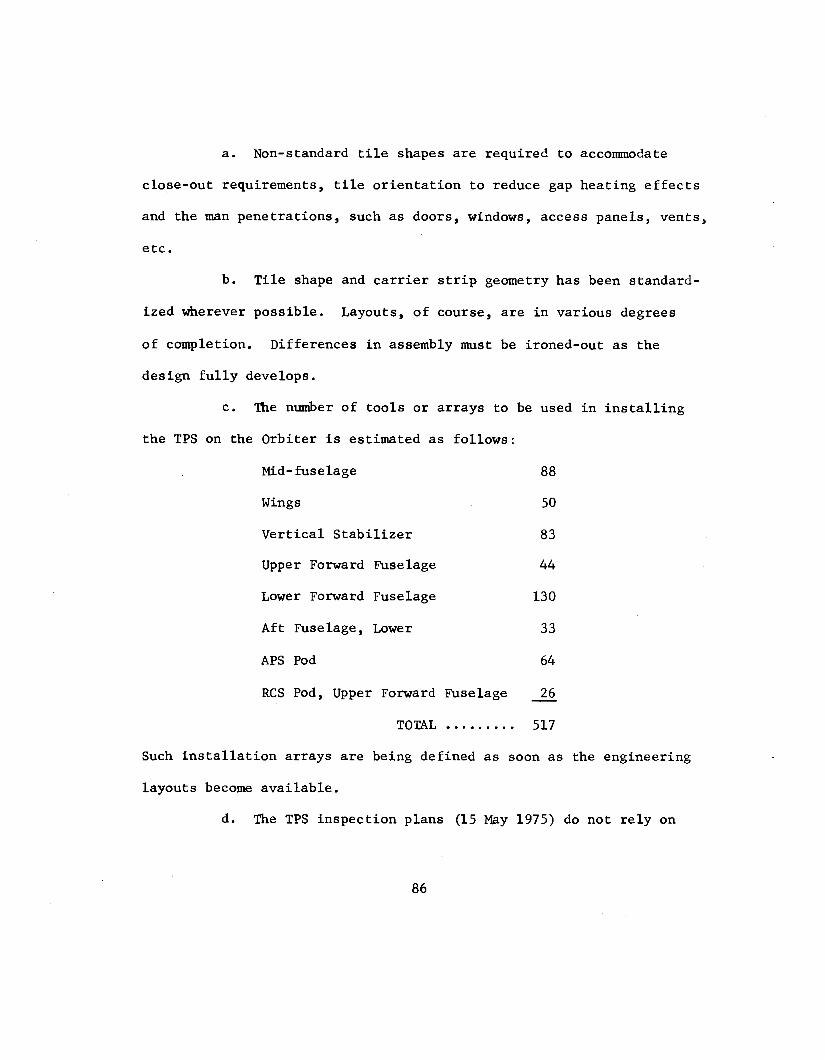
a. Non-standard tile shapes are required to accommodate
close-out requirements, tile orientation to reduce gap heating effects
and the man penetrations, such as doors, windows, access panels, vents,
etc.
b. Tile shape and carrier strip geometry has been standard-
ized wherever possible. Layouts, of course, are in various degrees
of completion.
design fully develops.
Differences in assembly must be ironed-out as the
c. The number of tools or arrays to be used in installing
the TPS on the Orbiter is estimated as follows:
Mid-fuselage
Wings
Vertical Stabilizer
Upper Forward Fuselage
Lower Forward Fuselage
Aft Fuselage, Lower
APS Pod
RCS Pod, Upper Forward Fuselage
TOTAL .........
88
50
83
44
130
33
64
26
517
-
Such installation arrays are being defined as soon as the engineering
layouts become available.
d. The TPS inspection plans (15 May 1975) do not rely on
86

visual inspection alone as the initial method of damage inspection.
Demage, of course, can occur during assembly or as a result of the
mission environment. The intent of the visual inspection is to iden-
tify both those vehicle areas where there is obvious damage as well
as those areas which warrant more detailed assessment because of the
external appearance of the tile or similar data. This visual tech-
nique is an effective process to identify areas of refurbishment.
Detailed discussion of available NDE (Non-Destructive Evaluation)
tests and future plans for such are contained in Rockwell International
Letter 044-250-75-080, dated 5 August 1975.
e. An example of the attention being focused on the instal-
lation problem at this time is the assignment of twelve quality engi-
neers to work directly with the design group during the current phase
of the program. NASA has also assigned a quality engineer to monitor
the effort on a full-time basis. In addition, a TPS development shop
is located adjacent to the design area to assure continuity between
the development testing and the design and quality verification
efforts.
4.2.7 Logistics and Maintenance
Much of what has been stated above for the fabrication and
assembly portion of the TPS program applies to the logistics and
maintenance areas as well. These areas are receiving increasing
87

attention as the design moves forward. For example, Rockwell Inter-
nationa is responding to a KSC request for a proposal to develop
Space Shuttle thermal protection system refurbishment techniques,
which consists of three basic tasks: (1) tile removal and replacement,
(2) tile repair, and (3) thermal tile tests at KSC to verify repair
methods.
These tasks started in October 1975 and wi?l be completed on or
about October 1976.
Handling and packaging specifications and procedures are to be
prepared so that the documents covering the TPS handling, storage,
transportation, inspection, bonding, machining and coating, and water-
proofing will be published and ready in time to support the TPS fa-
cilities activation at the Pahdale assembly plant.
TPS tile identification methods are under active consideration
with a goal of identifying the tiles with an applicable Rockwell
International part number and serial number on the bottom surface
of the tile.
4 . 3 Current Posture
Although basically a new system, the program considers the
Orbiter TPS concept appears to be both practical and workable. De-
sign and development testing appears to support this judgment. An
example of the maturation of the TPS design is the large reduction in
88

the number of thin (0.20") tiles resulting from the refinement ,f en-
try aerothermal loads and the development of coated Nomex felt for those
Orbiter surfaces having expected temperatures below the 650-700' F.
range.
Based on the data available to the Panel, the following is the
status of TPS development:
a. It is expected that 95% of the layout drawings wwufd
be completed by April 1976.
b. The TPS design, fabrication, installation and test
activities should meet the Orbiter 102 program milestone requirements.
c . The TPS system design reviews are effective in surfacing
those kinds of problems requiring the attention of management and the
working levels to assure the TPS meets the requirements on Orbiter 102.
d. The Solid Rocket Booster separation rocket engine plumes
do not appear to present an impingement problem.
e. The basic TPS materials have been selected and the
"acreage" configuration have been baselined. The interface config-
uration between the leading edge RCC system and the basic tile system
has been finalized.
Specifications and test plans need to be completed as follows:
a. The Lockheed Mssile and Space Corporation specification
on "heat-up" and "cool-down" rates to assure the tile materials meet
89

Orbiter requirements requires further definition.
b. The material property data in Rockwell International
handbooks used by design and test personnel needs to be updated.
c. The TPS Design Specification, SD72-SH-0101-6, is to
be updated and completed on or about July 1, 1976 by Rockwell
International.
d. Requirements for acoustic fatigue tests need to be
verified.
e. There needs to be a demonstration of a full 100 mission
life for the carbodcarbon leading edge material (RCC), especially
for that section of the wing leading edge where the shock wave off
the Orbiter nose intersects the wing.
f. Aerodynamic heating in the gaps between TPS tiles is
a problem where much effort is being expended at this time. This is
most severe in those portions of the tile system where a large pressure
gradient is present causing increased local flow rates, such as on the
wing glove area at high angles of attack.
g. A test and analysis program must be defined to prove
that the coated tiles can meet the waterproof requirements necessary
for re-use. Coating development activity indicates that this is a
difficult area and resolution is expected in mid-1976.
h. The requirements for Development Flight Instrumentation
90
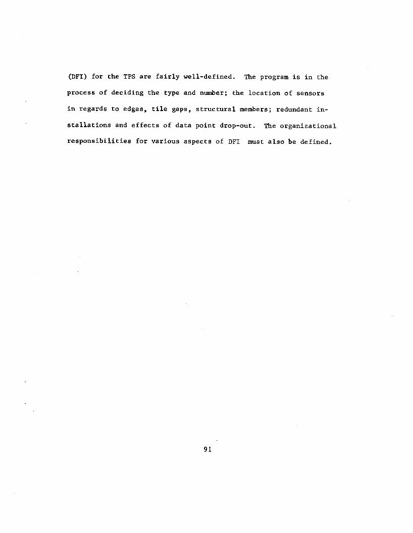
(DFI) for the TPS are fairly well-defined. The program is in the
process of deciding the type and number; the location of sensors
in regards to edges, tile gaps, structural members; redundant in-
stallations and effects of data point drop-out.
responsibilities for various aspects of DFI must also be defined.
The organizational
91

4.4 Addendum
The program has just completed a major baseline review and made
number of significant decisions.
4.4.1 Tile Coating
The Ames Research Center "RCG" coating has been selected for the
high temperature tiles (HRSI) based on the most recent test results
and detailed studies. This black coating should eliminate the coat-
ing cracking problem experience during the past months. The original
grey-colored coating will be used on the low temperature tiles (LRSI)
which has not experienced the cracking problem. The thermal properties
(emissivity/absorbtivity) appear to meet requirements.
4.4.1 SSME Heat Shields
The thermal protection system design for SSME base heat shield
is shown in Figure 4-3. This shield protects the Orbiter and engine
structure from heat transfer during the ascent and entry portions
of the mission. It has been estimated that one-half of the shield
on a single engine may have to be replaced every four or so flights.
4.4.3 Thermal Seals
The Orbiter body flap and wing/elevon lower cove aerothermal
seals require failsafe design. As presently designed these may pre-
sent a single point failure condition which can be considered a crew
92

safety hazard. Furthermore these seals as designed are dynamic systems
so that safe-life cannot really be proven and inspection for failures
is extremely difficult. Although these seal systems include springs,
hinges, linkages, rubbing plates they are not subjected to the form
of failure mode and effects analyses (FMEA's) used on other mechanisms
because they are considred to be structures. The contractor has noted
that reliability trade studies have beer. conducted to support the de-
sign and development and the test program.
The test and analysis program for the seals is directed toward
demonstrating that:
a. Sufficient structural and performance margins exist so
that there is no credible single point failure in the seal system.
b. Sufficient access and ground test provisions have been
provided to permit inspection and tests to prove flight readiness.
c. Where structural and performance margins cannot be
demonstrated the design shall incorporate sufficient thermal protection
to accommodate a safe single entry by means of insulation, heat sinks,
etc. To assure hat the current design approach meets the requirements
the contractor has been directed to review the following areas and
develop a plan and a schedule to (1) determine if the present design
can be made failsafe for all flights, (2) reassess maximum gap size
allowables, (3) determine if additional test program will increase
93

confidence, ( 4 ) invest igate the inspection and maintenance concepts
f o r increasing the a b i l i t y t o meet turnaround times, and (5) Invest i -
gate poten t ia l modifications to ear ly t e s t missions t o enhance the f a i l -
safe concept.
Other areas of thermal s e a l s s t i l l being analyzed include the
following :
a . The impact of accommodating ear ly boundary layer tran-
s i t i o n with p a r t i c u l a r a t t e n t i o n given to the forward landing gear
door and the external tank/Orbiter/forward attachment points.
b. Use of redundant s e a l systems based on the r e s u l t s of
the a c t i v i t i e s noted above under the elevon and body f l a p sea ls .
c. Payload Bay Door areas.
d . The External Tank Umbilical Door sea l .
e. Mechanical propert ies of thermal brush systems used
i n the s e a l and b a r r i e r systems.
f . Door rigging on those doors t h a t might have s igni f icant
def lect ions during the mission.
4 . 4 . 4 Thermal Barr iers
In addi t ion t o the thermal b a r r i e r mater ia ls used i n the sea ls
around doors and the l ike , there i s a l s o a need for thermal b a r r i e r s
o r "gap fi l lers" between t i l e s and between t i l e s and adjacent s t ruc tures
such a s windows, the elevon t r a i l i n g edge, the wing glove and chine,
94

e tc . Results from wind tunnel t es t s c l e a r l y ind ica te tha t gap heating
i s s i g n i f i c a n t l y increased when flow i s driven by a high pressure
gradient. The amount of heating increase i s dependent upon the mag-
nitude of the gradient.
i s experienced a t a surface temperature of 1400' F. while a gap tem-
perature of some 2000' F. resu l ted a t a surface temperature of 1600° F.
General areas of the TPS where pressure gradients e x i s t and where gap
f i l l e r s a r e required have been iden t i f i ed .
For example, a gap temperature of 1490° F.
Concepts devised t o meet t h i s problem include:
a . Thermal brush bonded t o t i l e s ides .
b. Glass fabr ic shapes bonded to t i l e s ides .
c . S a f f i l f i be r s encapsulated i n I r i s h Refras i l mater ia i
and bonded t o the f i l l e r bar cur ren t ly i n use,
d. S a f f i l f i be r s plus a kn i t t ed wire mesh spring encapsulatt-A
i n a high temperature f ab r i c (AB 312) and bonded to the f i l l e r bar.
Since the bonding o f the t i l e and coating h<js not been s a t i s -
factory to da te , the program i s considering the use of S a f f i l f i be r s
made in to a brush ( S a f f i l = s i l i c a f i b e r s ) o r encapsulated and b o n r l ~ ~ i
t o che f i l l e r bar ra ther than the t i l e coating.
These designs a re being tes ted both thermally and s t r u c t u r a l l }
a t t h i s time.
4.4.5 Ti le Step and Gap Effects
95

There appears to be a great deal of difficult in maintaining the
small/step and gap required between tiles to prevent early boundary
layer transition. For instance the nose landing gear door thermal
barrier arrangement produces a 0.025-inch step at forward and aft
door edges compared with present requirements for not more than 0.017-
inch step. The gap between thermal tiles at the same door edges are
in excess of the requirement for 0.034-inch width and 0.034-inch depth.
Analytical and test work continues in such areas to bring the step and
gap problem within allowable bounds.
4.4.6 Structural Thermal Analyses
The approach to the structural thermal analysis is such that it
supports the development of structural and TPS designs that are inter-
dependent. The time that it takes to do a complete thermal and stress
analysis calculation or iteration on a previous calculation is quite
long. These programs are large, complex 3-dimensional mathematical
models requiring considerable manpower and computer usage. These pro-
grams do not include all three-dimensional effects that influence the
structural temperature gradients because Orbiter design schedules pre-
clude that level of detail. Those three-dimensional effects provided
as given inputs are parameters that vary longitudinally as well as
transversely, e.g., TPS thickness, heat loads, primary structure, and
TCS insulation. The Contractor's TPS minimum weight thermal design

and analysis philosophy is to establish R S I thickness requirements
and vehicle temperature response based on nominal thermal analyses
for aborts as well as normal WTR and ETR missions. All these analyses
are planned to be accomplished at a level of detail consistent with
Shuttle program funding and schedules. Final vehicle overall thermal
and structural capability i s to be determined through a progressive
flight test program. Predicated on flight test results, design modi-
fications can be effected if required to maintain adequate vehicle
operational capability.
97

ATTACHMENT 4-1
Thc d i i s i q n a n d q u a l i t y c o n t r o l for t h e doors, T h e r m a l Protc:c:t.ior-L S y s t e m p e n e t r a t i o n s a n d t h e r m a l seals s h o u l d h e c l o s e l y monitored b y management to a s s u r e t h a t t h e r e l i a b i - l i t y n e c e s s a r y t o s a t i s f y s a f e t y w i l l be a c h i e v e d .
Rc>sponse: - Tlie c r i t i c a l i t y of r e l i a b l e d e s i g n s for d o o r s a n d o t h e r p c r ~ c t i - ~ ~ t i o n t : t h r o u g h t h e TPS a n d t h e associated s t a t i c a n d clynain; c s ~ > ~ i l s i s r c c - o q n i z e d by rnanagemcnt. The c l o s i n g and l a t c h i n g mccha- ni::nis f o r t h c d o o r s a n d h a t c h e s w e r e i d e n t i f i e d as SPP’s i n t h e FMl?A as 1cLidiiicj t o f a i l u r e t o close a n d p o t e n t i a l c a t e g o r y 1 e f f e c t s . ‘l’hcsc. c r i t i c a l mechan i sms ar,d re la ted t h e r m a l seals h a v e a l s o bc:en i d c n t i fied i n the O r b i t e r H a z a r d s Ana1ys j . s . C o n c e r n w a s exprcssed a b o u t thc i n i i i i a tu r i ty of d e s i g n of t h i s p a r t of t h e t h e r m a l protec- t i o n s y s t e m d u r i n g t h e TPS PDi? f o r v e h i c l e 1 0 2 c o n d u c t e d i n e a r l y A u c j u s t . S c l i c d u l e m i l e s t o n e s h,ivc b e e n c s t a b l - i s h c d for n e a r tcrm ad jit:;tmc:nts .in the d c s i y n effort t o a s s u r e s F A t i s f C i c t o r y m a i i j i n s . ‘I’Ii t- I’roclram I1 i rector has been a p p r i s e d of t h e s t a t us 2nd a(.col:p1 i s h - m c ’ n t of thc m i l c3s toncs w i 11 bc> monitored.
I t r ; l~ould cil:;o be notccl t h a t the. o v e r a l l S p a c e Shut t l c d e s i q i i h b s hcc\n reviewcxcl w i t h thc o b j e c t - i v c of m i n i m i z i n g the n u m b e r of TI’S pc.iic\Cr,itions. F o r exai i iple , as a r e s u l t or‘ a revicw of doors nc l w t c d i i i f I i q h t , t h e forward RCS i n s t a l l a t i o n was modified t o e l i i n i r i n t c the. doors.
98

ATTACHMEm 4-2
The p r o c e d u r e s , i n s t r u c t i o n s , and t r a i n i n g r e q u i r e m e n t s f o r i n s t a l l a t i o n and q u a l i t y con t ro l . of t h e T h e r m a l P r o t e c t i o n Sys tem components s h o u l d be rev iewed by program management t o assure t h e aero/ thcrmodynamic r e q u i r e m e n t s are m e t .
Rcsponse: The TPS (Thermal P r o t e c t i o n System) j .s s t i l l i n t h e dcvelopmcnt s tage ; t h e r e f o r e , t h e d e t a i l e d i n f o r m a t i o n r e g a r d i n g t h e p r o c e s s for i n s t a l l a t i o n and v e r i f i c a t i o n of: the TPS i s alc; under dcvel.opmcnt. S i g n i f i c a n t a t t e n t i o n i s b e i n g focused on th i . s irrcrl by both t h e c o n t r a c t o r and NASA. For exanip.lci, t o assurc t h c l y and ndcquatc d e v e l o p i c n t of q u a l i t y c r i . t c r i . a f o r t h e TPS i n s t a l l a t i o n and v e r i f i c a t i o n p r o c e s s , t h e contractor h a s assiynpd 3 % q u a l i t y e n g i n e e r s t o work d i r e c t l y wi.th t h e d e s i g n group d u r i n q i:hc des ig i i and devc?l.opment phase of t h e e f f o r t . NASA h a s a s s j q r i e d n quality e n g i n e e r t o moni tor t h e e f f o r t o n c? f u l . l t i m e 1, ; ls j~s. A TPS dcvel-opment shop i s l o c a t e d adjacent t o tl1e d e s i g n Ftrea t o assurc c o n t i n u i t y between t h e development tes t i n q and t.hc dclsi.cn iind q u a l i t y v e r i f i c a t i o n e f f o r t s . ND13 ( n o n d c s t r u c t i v e cvaluat ioi-1) tcchniques a re c u r r e n t l y b e i n q deve loped and ?;c?stnd t o assure d c t e c t j n n of d e l a m i n a t i o n of V i l e b o n d s , m a t e r i a l v o i d s , c r acks , otc. , foI1.otring i n s t a l l a t i o n and f l i q h t . Persoiine1. t r a l . n i n g ar?d c e r t i f i c a t i o n r e q u i r e m e n t s arc b e i n g deve loped CoTicurrent w i t h t h e i n s t a l . l a t i o n and i n s p e c t i o n p r o c e s s e s .
The TPS i s a n a r e a of grea t c o n c e r n t o managcincnt and it i s because of t h i s c o n c e r n t h a t t h e a c t i o n w a s t a k e n t o ass i .gn d e s i g n , q u a l i t y e n g i n e e r i n g , and m a n u f a c t u r i n g p e r s o n n c l to d e v e l o p t h e n e c e s s a r y v e r i f i c a t i o n processes c o n c u r r e n t w i t h development of the d e s i g n . F r e q u e n t reviews are conducted by 130th the c o n t r a c t o r and NASA nianagemerit t o m a i n t a i n f u l l v i s i b i l i t y 01 p r o g r e s s and problems e n c o u n t e r e d i n t h e TPS development .
----
99

DATE
Feb 1974
Aug 1974
Sep 1974
Jan 1975
Mar 1975
May 1975
J u l 1975
Aug 1975
O c t 1975
May 1976
TABLE 4-1
ORBITER THERMAL PROTECTION SYSTEM ACTIVITIES
LOCAT I O N
JSC
ARC Lockheed
R I
JSC
KS C
R I
JSC
R I Pa lmda l e
R I
JSC
SUBJECT
Review o f s i g n i f i c a n t s h u t t l e d e c i s i o n s and s t a t u s
T e s t and materials development review and examina- t i o n of materials characterization/fabrication
O r b i t e r TPS
Level I1 (Systems I n t e g r a t i o n ) a s p e c t s of TPS
I n s p e c t i o n , r e p a i r , maintenance a s p e c t s o f TPS
More d e t a i l e d f a c t f i n d i n g a s s o c i a t e d w i t h TPS t e s t i n g , i n s t a l l a t i o n , maintenance, s a f e t y impacts
TPS d e s i g n , i n s t a l l a t i o n , t e s t s , s a f e t y implica- t i o n s a s s o c i a t e d w i t h door and v e n t p r o t e c t i o n
TPS assembly f o r O r b i t e r 101 and 102 P a r t i c i p a t e i n TPS Design Review
R e s u l t s of O r b i t e r 101 CDR and i n p u t t o 102 PDR
R e s u l t s of O r b i t e r 102 PDR r e l a t i n g t o TPS
100

TABLE 4-2
DOCUMENTS ASSOCIATED WITH ORBITER TPS
1. O r b i t e r Thermal P r o t e c t i o n Subsystem (TPS) Design Review Board Minutes. 14 August 1975.
2. TPS Design Review summary b r i e f i n g s , system d e s c r i p t i o n b r i e f i n g , team board b r i e f i n g s , Review I t e m D i s p o s i t i o n Summary, R I D and t e a m minutes; a l l pub l i shed i n R I document SSV75-24-1 d a t e d 14 Aug 75 .
3 . T y p i c a l R I I n t e r n a l L e t t e r s r e l a t i n g t o TPS: "TPS Eva lua t ion o f Updated Design T r a j e c t o r y Miss ion 3B" A p r i l 30, 1975 "TPS Eva lua t ion of AOA Trajectory-Nominal WTR" June 16 , 1975 "Thermal Eva lua t ion of OML F a i r e d TPS Thickness f o r OV 102" J u l y 24, 1975 "TPS Eva lua t ion of ETR T r a j e c t o r y With Di spe r s ions" August I , 1975
4. " S h u t t l e O r b i t e r OV-101 CDR S a f e t y Ana lys i s Report Volume I- Management Summary" 15 September 1975, SD75-SH-0135-001. " S h u t t l e O r b i t e r OV-101 CDR S a f e t y Ana lys i s Report Volume II- S t r u c t u r e s " 15 September 1975, SD75-SH-0135-002. " S h u t t l e Systems S a f e t y Ana lys i s Report" June 1 5 , 1975, SD75-SH-0064A "Space S h u t t l e S a f e t y Concerns Surmnary Report" 5 September 1975. S h u t t l e O r b i t e r 102 PDR S a f e t y A n a l y s i s Report (Update), SD74-SH-0323, I t
d a t e d J u l y 1, 1975.
101

TABLE 4 - 3
Review I t e m Disposit ion (RID)
From Previous Reviews
S t i l l Open
LESS/HRSI Gap/Step Tolerance
LESS s t r u c t u r a l and Dynamic Analysis
LESS/HRSI In t e rna l Insulat ion
RSI Attachment Around Windows
Thermal Deflection of RCC Expansion Seal
LESS Designs f o r Baseline Trajectory
(These ind ica te the areas of some concern from a standpoint of design
completion and understanding of the problems involved i f not resolved)
102

Tab le 4-4
F e l t Reuseable Sur face I n s u l a t i o n (FRSI)
1. Th i s i s Nomex o r "E" f e l t coa ted w i t h w h i t e s i l i c o n e ox ide ( D C 9 2 - 0 C 7 )
2 . The use o f t h i s m a t e r i a l i n l i e u of t i l e s saves about 345 pounds
3 . P h y s i c a l P r o p e r t i e s - Maximum a l l o w a b l e t e m p e r a t u r e f o r one mis s ion 900'F - 100 Mission L i f e Maximum a l l o w a b l e temperature 700°F - Dens i ty , l b s / f t 2 w i t h t h i c k n e s s of 0.4 i nches 0.24 - Coating t h i c k n e s s (DC92-007) 0.0075 inches - Area covered, f t 2 2800
4. Manufactur ing process Nomex f e l t is h e a t t r e a t e d t o 700°F f o r 30 minu tes , then i t i s t r e a t e d a t a r a i s e d temperature of 750°F f o r a n o t h e r 30 minu tes . Th i s accomplishes t h e p re - sh r inkage s t e p . A f t e r a p p l i c a t i o n of t h e c o a t i n g (DC92-007) t h e r e is a p o s t c u r e f o r 15 minutes a t 650°F.
103
4-1 ORBITER THERMAL PROTECT 1014 SUBSYSTEM
RE I NFORCED CARBON-CARBON
SURFACE I N S U L A T I O N
LOW TEMPERATURE REUSABLE SURFACE I N S U L A T I O N
[3 H I G H TEMPERATURE REUSABLE
H C O A T E D NOMEX F E L T
METAL OR GLASS
:s I