attachment 3 vegetation mapping - planit …€¦ · white acronychia rutaceae shrub/tree 12...
TRANSCRIPT


ATTACHMENT 3
VEGETATION MAPPING

NO
RTH
LEG
END
OPE
N A
REAS
/PAD
DO
CKS
WIT
H S
CATT
ERED
MAT
URE
TRE
ES &
REG
ROW
TH
OPE
N E
UCA
LYPT
FO
REST
/EU
CALY
PTW
OO
DLA
ND
RIPA
RIAN
/RIV
ERIN
E AS
SOCI
ATIO
N
BR
OA
D V
EGET
ATI
ON
CO
MM
UN
ITY
M
AP
PIN
G
FOR
FIN
CH
RO
AD
, CA
NU
NG
RA
* Bo
unda
ries
app
roxi
mat
ed f
rom
aeri
al p
hoto
grap
hy,
cont
ours
, ha
ndhe
ld G
PS c
oord
inat
es a
nd s
ite
insp
ecti
ons
but
have
not
bee
n de
linea
ted
by a
sur
veyo
r

NO
RTH
LEG
END
OPE
N A
REAS
/PAD
DO
CKS
WIT
H S
CATT
ERED
MAT
URE
TRE
ES &
REG
ROW
TH
DRY
SC
LERO
PHYL
L W
OO
DLA
ND
/OPE
NFO
REST
(M
IXED
CAN
OPY
OF
STRI
NG
YBAR
K,IR
ON
BARK
, G
UM
S &
AL
LOCA
SUAR
INA.
BRU
SH B
OX
IN D
RY G
ULL
IES)
WET
SCL
ERO
PHYL
L FO
REST
(CAN
OPY
DO
MIN
ATED
BY
BLAC
K TE
E TR
EE)
TALL
WET
SCL
ERO
PHYL
L FO
REST
(CAN
OPY
D
OM
INAT
ED
BY
BRU
SH
BOX,
GRE
Y G
UM
, FLO
OD
ED G
UM
& H
OO
P PI
NE)
RIPA
RIAN
/RIV
ERIN
E AS
SOCI
ATIO
N
VEG
ETA
TIO
N S
UB
-ALL
IAN
CE
MA
PP
ING
FOR
FIN
CH
RO
AD
, CA
NU
NG
RA
* Bo
unda
ries
app
roxi
mat
ed f
rom
aeri
al p
hoto
grap
hy,
cont
ours
, ha
ndhe
ld G
PS c
oord
inat
es a
nd s
ite
insp
ecti
ons
but
have
not
bee
n de
linea
ted
by a
sur
veyo
r

ATTACHMENT 4
FLORA SPECIES LIST

FLO
RA
SU
RVE
Y SP
ECIE
S LI
ST -
CA
NU
NG
RA
(RIF
LE R
AN
GE)
Surv
eyed
and
com
pile
d by
: J
an A
llen,
Mar
k Jo
nes
& G
raha
m D
art
Dat
e:
Jun
e-Ju
ly 2
004
SPEC
IES
LIST
ALP
HA
BET
ICA
LLY
BY
GEN
US/
SPEC
IES
No.
GEN
US/
SPEC
IES
CO
MM
ON
NA
ME
FAM
ILY
TYPE
STA
TUS
1A
butil
on a
uritu
mM
alva
ceae
Shr
ub2
Aca
cia
disp
arrim
a H
icko
ry W
attle
Mim
osac
eae
Tree
3A
caci
a fa
lcat
aW
attle
Mim
osac
eae
Shr
ub/tr
ee4
Aca
cia
fimbr
iata
Frin
ged
Wat
tleM
imos
acea
eS
hrub
/tree
C R
E,F
5A
caci
a le
ioca
lyx
Cun
ning
ham
's W
attle
Mim
osac
eae
Shr
ub/tr
ee6
Aca
cia
mai
deni
iM
aide
ns W
attle
Mim
osac
eae
Shr
ub/tr
ee7
Aca
cia
mel
anox
ylon
Bla
ck W
attle
Mim
osac
eae
Tree
8A
caci
a po
daly
riifo
liaQ
ld S
ilver
Wat
tleM
imos
acea
eS
hrub
9A
caly
pha
nem
orum
Eup
horb
iace
aeS
hrub
10A
cmen
a sm
ithii
Cre
ek L
illy
Pill
yM
yrta
ceae
Shr
ub/tr
ee11
Acr
onyc
hia
oblo
ngifo
liaW
hite
Acr
onyc
hia
Rut
acea
eS
hrub
/tree
12A
dian
tum
atro
virid
e S
oft M
aide
nhai
rA
dian
tace
aeFe
rn13
Adi
antu
m h
ispi
dulu
mR
ough
Mai
denh
air
Adi
anta
ceae
Fern
14A
gera
tina
aden
opho
raC
rofto
n W
eed
Ast
erac
eae
Her
b/sh
rub
* P
315
Age
ratin
a rip
aria
Mis
t Wee
dA
ster
acea
eH
erb/
shru
b*
P3
16A
gera
tum
con
yzoi
des
Bill
ygoa
t Pla
ntA
ster
acea
eH
erb
*17
Alc
horn
ea il
icifo
liaN
ativ
e H
olly
Eup
horb
iace
aeS
hrub
/tree
18A
lect
ryon
tom
ento
sus
Hai
ry A
letry
onS
apin
dace
aeTr
ee19
Allo
casu
arin
a lit
tora
lisB
lack
She
-oak
Cas
uarin
acea
eTr
eeC
RE
, F20
Allo
casu
arin
a to
rulo
saFo
rest
She
oak
Cas
uarin
acea
eTr
ee21
Alp
hito
nia
exce
lsa
Red
Ash
Rha
mna
ceae
Tree
22A
lpin
ea c
aeru
lea
Nat
ive
Gin
ger
Zing
iber
acea
eH
erb
23A
mbr
osia
arte
mis
iifol
iaA
nnua
l Rag
wee
dA
ster
acea
eH
erb
* P
3 24
And
ropo
gon
virg
inic
usW
hisk
ey G
rass
Poa
ceae
Her
b*
25A
neile
ma
acum
inat
umN
ativ
e W
ande
ring
Jew
Com
mel
inac
eae
Her
b26
Ang
opho
ra le
ioca
rpa
Sm
ooth
Bar
ked
App
leM
yrta
ceae
Tree
27A
ngop
hora
sub
velu
tina
Rou
gh B
arke
d A
pple
Myr
tace
aeTr
ee

No.
GEN
US/
SPEC
IES
CO
MM
ON
NA
ME
FAM
ILY
TYPE
STA
TUS
28A
phan
anth
e ph
illip
ensi
sR
ough
Elm
Ulm
acea
eS
hrub
/tree
29A
rauc
aria
cun
ning
ham
iiH
oop
Pin
eA
rauc
aria
ceae
Tree
30A
scle
pias
cur
assa
vica
Red
head
cot
ton
bush
Asc
lepi
dace
aeS
hrub
*31
Asc
lepi
as p
hyso
carp
usB
allo
on c
otto
n bu
shA
scle
pida
ceae
Shr
ub*
32A
sple
nium
aus
trala
sicu
mB
ird's
Nes
t Fer
n A
sple
niac
eae
Fern
C R
E33
Ast
rotri
cha
latif
olia
Ara
liace
aeS
hrub
34A
ustro
teen
sia
blac
kii
Blo
od V
ine
Faba
ceae
Vin
e35
Axo
nopu
s af
finis
Car
pet g
rass
Poa
ceae
Her
b*
36B
abin
gton
ia s
imili
s (s
yn. B
aeck
ea v
irgat
a)Tw
iggy
Bae
ckea
Myr
tace
aeS
hrub
37B
acch
aris
hal
imifo
liaG
roun
dsel
Ast
erac
eae
Shr
ub*
P3,
P4
38B
ackh
ousi
a m
yrtif
olia
Wee
ping
Myr
tleM
yrta
ceae
Tree
39B
alog
hia
inop
hylla
S
crub
Blo
odw
ood
Eup
horb
iace
aeTr
ee40
Bid
ens
pilo
saC
obbl
ers
Peg
sA
ster
acea
eH
erb
*41
Bra
chia
ria m
utic
aP
ara
gras
sP
oace
aeH
erb
*42
Bre
ynia
obl
ongi
folia
Cof
fee
Bus
hE
upho
rbia
ceae
Shr
ub43
Brid
elia
exa
ltata
Bru
sh Ir
onba
rkE
upho
rbia
ceae
Tree
44B
rom
us c
atha
rtica
Pra
irie
Gra
ssP
oace
aeH
erb
*45
Bur
saria
spi
nosa
Pric
kly
Pin
eP
ittos
pora
ceae
Shr
ubC
RE
,F46
Cal
lery
a m
egas
perm
a N
ativ
e W
iste
riaFa
bace
aeV
ine
47C
allis
tem
on s
alig
nus
Whi
te B
ottle
brus
hM
yrta
ceae
Tree
C R
E,F
48C
allis
tem
on v
imin
alis
Wee
ping
Bot
tlebr
ush
Myr
tace
aeS
hrub
/tree
C R
E,F
49C
aloc
asia
sp
Ele
phan
t Ear
sA
race
aeH
erb
*50
Cal
ochl
aena
dub
iaFa
lse
Bra
cken
Dic
kson
iace
aeFe
rnC
RE
,F51
Cal
otis
den
tex
Whi
te B
urr D
aisy
Ast
erac
eae
Shr
ub52
Car
issa
ova
taC
aris
saA
pocy
nace
aeS
hrub
53C
assi
a bi
caps
ular
isY
ello
w S
enna
Cae
salp
inia
ceae
Shr
ub*
54C
assi
a flo
ribun
daS
moo
th C
assi
aC
aesa
lpin
iace
aeS
hrub
*55
Cas
syth
a fil
iform
isD
odde
rLa
urac
eae
Vin
e56
Cas
tano
sper
mum
aus
trale
Bla
ckbe
anFa
bace
aeTr
ee57
Cas
uarin
a cu
nnin
gham
iana
Riv
er O
akC
asua
rinac
eae
Tree
58C
ayra
tia c
lem
atid
eaS
lend
er G
rape
Vita
ceae
Clim
ber
59C
elas
trus
aust
ralis
Sta
ff vi
neC
elas
trace
aeV
ine
60C
eltis
sin
ensi
sC
hine
se C
eltis
Ulm
acea
eTr
ee*

No.
GEN
US/
SPEC
IES
CO
MM
ON
NA
ME
FAM
ILY
TYPE
STA
TUS
61C
ente
lla a
siat
ica
Got
u K
ola
Api
acea
eH
erb
*62
Cen
trant
heru
m p
unct
atum
Ast
erac
eae
Her
b63
Che
ilant
hes
sieb
eri
Mul
ga F
ern
Sch
izea
ecea
eFe
rn64
Chl
oris
gay
ana
Rho
des
Gra
ssP
oace
aeH
erb
*65
Chr
iste
lla d
enta
taB
inun
gTh
elyp
terid
acea
eFe
rn
66C
hrys
ocep
halu
m a
picu
latu
m
Yel
low
But
tons
Ast
erac
eae
Her
b67
Cin
nam
omum
cam
phor
aC
amph
or L
aure
lLa
urac
eae
Tree
*68
Cirs
ium
vul
gare
Spe
ar T
hist
leA
ster
acea
eH
erb
*69
Cis
sus
anta
rctic
aW
ater
Vin
eV
itace
aeV
ine
70C
issu
s hy
pogl
auca
Five
leaf
Wat
er V
ine
Vita
ceae
Vin
e71
Cis
sus
opac
aS
mal
l lea
f Wat
er V
ine
Vita
ceae
Vin
e72
Citr
ioba
tus
pauc
iflor
usO
rang
e Th
orn
Pitt
ospo
race
aeS
hrub
73C
itrus
lim
onLe
mon
tree
Rut
acea
eTr
ee/s
hrub
*74
Cla
oxyl
on a
ustra
leB
rittle
woo
dE
upho
rbia
ceae
Shr
ub/tr
ee75
Cle
ista
nthu
s cu
nnin
gham
iiO
meg
aE
upho
rbia
ceae
Tree
76
Cle
mat
is g
lyci
noid
esH
eada
che
Vin
eR
anun
cula
ceae
Vin
e77
Cle
rode
ndru
m fo
ribun
dum
Lolly
Bus
hV
erbe
nace
aeS
hrub
/tree
78C
lero
dend
rum
tom
ento
sum
Hai
ry L
olly
Bus
hV
erbe
nace
aeS
hrub
/tree
79C
omm
elin
a cy
anea
Wan
derin
g Je
wC
omm
elin
acea
eH
erb
*80
Com
mer
soni
a ba
rtram
iaB
row
n K
urra
jong
Ste
rcul
iace
aeTr
ee81
Cor
dylin
e co
nges
taP
alm
Lily
Aga
vace
aeS
hrub
82C
ordy
line
petio
laris
Pal
m L
ilyA
gava
ceae
Shr
ub83
Cor
ymbi
a ci
triod
ora
Spo
tted
Gum
Myr
tace
aeTr
ee84
Cor
ymbi
a gu
mm
ifera
Red
Blo
odw
ood
Myr
tace
ae
Tree
85C
orym
bia
inte
rmed
iaP
ink
Blo
odw
ood
Myr
tace
ae
Tree
86C
orym
bia
tore
llian
aC
adag
aiM
yrta
ceae
Tree
87C
oym
bia
tess
ella
risM
oret
on A
shM
yrta
ceae
Tree
88C
rota
laria
inca
naC
rota
laria
Faba
ceae
Her
b89
Cry
ptoc
arya
gla
uces
ens
Jack
woo
dLa
urac
eae
Tree
90C
rypt
ocar
ya tr
iplin
ervi
sB
row
n La
urel
Laur
acea
eS
hrub
/tree
91C
upan
iops
is n
ewm
anii
Long
leaf
Tuc
kero
oS
apin
dace
aeTr
ee2R
C92
Cym
bidi
um s
p in
d.O
rchi
dace
aeH
erb
C R
E93
Cym
bopo
gon
refra
ctus
Bar
bed
Wire
Gra
ssP
oace
aeH
erb

No.
GEN
US/
SPEC
IES
CO
MM
ON
NA
ME
FAM
ILY
TYPE
STA
TUS
94C
ynod
on d
acty
lon
Cou
chP
oace
aeH
erb
95C
yper
us b
revi
foliu
sM
ullu
mbi
mby
Cou
chC
yper
acea
eH
erb
*96
Cyp
erus
pol
ysta
chyo
sB
unch
y S
edge
Cyp
erac
eae
Her
b97
Dap
hnan
dra
tenu
ipes
Red
Flo
wer
ed S
ocke
twoo
dM
onim
iace
aeTr
ee98
Dav
allia
pyx
idat
aH
are’
s Fo
ot fe
rnD
aval
liace
aeFe
rnC
RE
99D
enha
mia
cel
astro
ides
Den
ham
iaC
elas
trace
aeTr
ee10
0D
erris
invo
luta
Nat
ive
Der
risFa
bace
aeV
ine
101
Des
mod
ium
gun
nii
Tick
-tref
oil
Faba
ceae
Shr
ub10
2D
esm
odiu
m ry
htid
ophy
llum
Rus
ty T
ick-
trefo
ilFa
bace
aeS
hrub
103
Des
mod
ium
unc
inat
um
Tick
-tref
oil
Faba
ceae
Shr
ub*
104
Dia
nella
cae
rule
a.Fl
ax L
ilyLi
liace
aeH
erb
105
Dia
nella
long
ifolia
Long
leav
ed F
lax
Lily
Lilia
ceae
Her
b10
6D
iche
lach
ne c
rinita
Plu
me
Gra
ssP
oace
aeH
erb
107
Dig
itaria
did
acty
laB
lue
Cou
chP
oace
aeH
erb
108
Dio
scor
ea tr
ansv
ersa
Nat
ive
Yam
Dio
scor
eace
aeV
ine
109
Dio
spyr
os fa
scic
ulos
aG
rey
Ebo
nyE
bena
ceae
Tree
110
Dod
onea
triq
uetra
Nat
ive
Hop
s B
ush
Sap
inda
ceae
Shr
ub11
1D
oodi
a as
pera
Pric
kly
Ras
p Fe
rnB
lech
nace
aeFe
rn11
2D
oodi
a m
edia
Com
mon
Ras
p Fe
rnB
lech
nace
aeFe
rn11
3D
rym
aria
cor
data
Trop
ical
Chi
ckw
eed
Car
yoph
ylla
ceae
Her
b11
4D
rype
tes
depl
anch
eiY
ello
w T
ulip
Eup
horb
iace
aeTr
ee11
5D
ysox
ylum
rufru
mH
airy
Ros
ewoo
dM
elia
ceae
Tree
116
Ecl
ipta
pro
stra
taE
clip
taA
ster
acea
eH
erb
*11
7E
laeo
carp
us o
bova
tus
Har
d Q
uand
ong
Ela
eoca
rpac
eae
Tree
118
Ela
eode
ndro
n au
stra
leR
ed O
live
Plu
mC
elas
trace
aeTr
ee11
9E
mbe
lia a
ustra
liana
Em
belia
Myr
sina
ceae
Vin
e12
0E
ndia
ndra
mue
lleri
Gre
en le
aved
Ros
e W
alnu
tLa
urac
eae
Tree
121
Ent
olas
ia s
trict
aW
iry P
anic
Poa
ceae
Her
b12
2E
ragr
ostis
tenu
ifolia
Ela
stic
Gra
ssP
oace
aeH
erb
123
Ere
chtit
es v
aler
iani
ifolia
Bra
zilia
n Fi
rew
eed
Ast
erac
eae
Her
b*
124
Ere
mop
hila
deb
ilis
Win
ter A
pple
Myo
pora
ceae
Her
b12
5E
ryth
rina
vesp
ertil
ioB
ats
Win
g C
oral
Tre
eFa
bace
aeTr
ee12
6E
ucal
yptu
s ac
men
oide
sW
hite
Mah
ogan
yM
yrta
ceae
Tree

No.
GEN
US/
SPEC
IES
CO
MM
ON
NA
ME
FAM
ILY
TYPE
STA
TUS
127
Euc
alyp
tus
bitu
rbin
ata
Gre
y G
umM
yrta
ceae
Tree
128
Euc
alyp
tus
carn
eaB
road
leav
ed W
hite
Mah
ogan
yM
yrta
ceae
Tree
129
Euc
alyp
tus
creb
raN
arro
w le
af Ir
onba
rkM
yrta
ceae
Tree
130
Euc
alyp
tus
euge
nioi
des
Stri
ngyb
ark
Myr
tace
aeTr
ee13
1E
ucal
yptu
s fib
rosa
Larg
e-le
aved
Iron
bark
Myr
tace
aeTr
ee13
2E
ucal
yptu
s gr
andi
sFl
oode
d gu
mM
yrta
ceae
Tree
133
Euc
alyp
tus
henr
yii
Larg
e Le
aved
Spo
tted
Gum
Myr
tace
aeTr
ee13
4E
ucal
yptu
s m
ajor
Gre
y G
umM
yrta
ceae
Tree
135
Euc
alyp
tus
mel
liodo
raY
ello
w B
oxM
yrta
ceae
Tree
136
Euc
alyp
tus
mic
roco
rys
Tallo
ww
ood
Myr
tace
aeTr
eeC
RE
,F13
7E
ucal
yptu
s m
oluc
cana
Gum
-top
ped
Box
Myr
tace
aeTr
ee13
8E
ucal
yptu
s pr
opin
qua
Gre
y G
umM
yrta
ceae
Tree
C R
E, F
139
Euc
alyp
tus
side
roph
loia
Q
ld G
rey
Ironb
ark
Myr
tace
aeTr
ee
140
Euc
alyp
tus
tere
ticor
nis
Fore
st R
ed G
umM
yrta
ceae
Tree
141
Euc
alyp
tus
tinda
liae
Q W
hite
Stri
ngyb
ark
Myr
tace
aeTr
ee14
2E
upom
atia
laur
ina
Bol
war
raE
upom
atac
eae
Shr
ub14
3E
ustre
phus
latif
oliu
sW
omba
t Ber
ryP
hile
siac
eae
Her
b14
4E
xoca
rpus
cup
ress
iform
isN
ativ
e C
herr
yS
anta
lace
aeS
hrub
145
Ficu
s co
rona
taC
reek
San
dpap
er F
igM
orac
eae
Tree
146
Ficu
s fra
seri
Cre
ek S
andp
aper
Fig
Mor
acea
eTr
ee14
7Fi
cus
mac
roph
ylla
Mor
eton
Bay
Fig
M
orac
eae
Tree
148
Ficu
s pl
atyp
oda
Roc
k Fi
g M
orac
eae
Tree
149
Ficu
s vi
rens
Whi
te F
igM
orac
eae
Tree
150
Ficu
s w
atki
nsia
naS
trang
ling
Fig
Mor
acea
eTr
ee15
1Fl
inde
rsia
aus
tralis
Teak
Rut
acea
eTr
ee15
2Fl
inde
rsia
ben
netti
ana
Ben
net's
Ash
Rut
acea
e Tr
ee15
3G
ahni
a as
pera
Sw
ord
Gra
ssC
yper
acea
eH
erb
C R
E15
4G
eito
nopl
esiu
m c
ymos
umS
cram
blin
g Li
lyP
hile
siac
eae
Her
b15
5G
eran
ium
sol
ande
riN
ativ
e G
eran
ium
Ger
ania
ceae
Her
b15
6G
loch
idio
n fe
rdin
andi
Che
ese
tree
Eup
horb
iace
aeTr
ee15
7G
loch
idio
n su
mat
ranu
mU
mbr
ella
Che
ese
Tree
Eup
horb
iace
aeTr
ee15
8G
lyci
ne c
land
estin
aG
lyci
neFa
bace
aeH
erb
159
Gly
cine
taba
cina
Gly
cine
Pea
Faba
ceae
Her
b

No.
GEN
US/
SPEC
IES
CO
MM
ON
NA
ME
FAM
ILY
TYPE
STA
TUS
160
Gna
phal
ium
sp.
ind.
Cud
wee
dA
ster
acea
eH
erb
161
Gom
phol
obiu
m la
tifol
ium
Gol
den
Glo
ry P
eaFa
bace
aeS
hrub
162
Goo
deni
a ro
tund
ifolia
Goo
deni
a G
oode
niac
eae
Her
b16
3G
revi
llea
robu
sta
Silk
y O
akP
rote
acea
eTr
ee16
4G
uioa
sem
igla
uca
Gui
oaS
apin
dace
aeTr
ee16
5H
akea
flor
ulen
taH
akea
Pro
teac
eae
Shr
ub16
6H
arde
nber
gia
viol
acea
Nat
ive
Sar
spar
illa
Faba
ceae
Vin
e16
7H
ibis
cus
hete
roph
yllu
sN
ativ
e R
osel
laM
alva
ceae
Shr
ub16
8H
yban
thus
enn
easp
erm
usS
pade
Flo
wer
Vio
lace
aeH
erb
169
Hyd
roco
tyle
laxi
folia
Stin
king
pen
nyw
ort
Api
acea
eH
erb
170
Hym
enos
poru
m fl
avum
Nat
ive
Fran
gipa
niA
pocy
nace
aeTr
ee17
1H
ypoc
hoer
is ra
dica
taFl
atw
eed
Ast
erac
eae
Her
b*
172
Impe
rata
cyl
indr
ica
varm
ajor
Bla
dy G
rass
Poa
ceae
Her
b17
3Ip
omea
cai
rica
Five
-leaf
Mor
ning
glo
ryC
onvo
lvul
acea
eV
ine
*17
4Ip
omea
pur
pure
aM
orni
ng g
lory
Con
volv
ulac
eae
Vin
e*
175
Jaca
rand
a m
imos
aifo
liaJa
cara
nda
Big
noni
acea
eTr
ee*
176
Jack
soni
a sc
opar
iaD
ogw
ood
Faba
ceae
Shr
ub17
7Ja
gera
pse
udor
hus
Foam
bark
Sap
inda
ceae
Tree
178
Ken
nedi
a ru
bicu
nda
Ken
nedy
Pea
Faba
ceae
Vin
e17
9La
ntan
a ca
mar
aLa
ntan
aV
erbe
nace
aeS
hrub
*18
0La
ntan
a m
onte
vide
nsis
Pur
ple
Lant
ana
Ver
bena
ceae
Shr
ub*
181
Laxm
anni
a gr
acili
sW
ire L
ilyA
nthe
ricac
eae
Her
b18
2Le
gnop
hora
moo
rei
Rou
nd L
eave
d V
ine
Men
ispe
rmac
eae
Vin
e18
3Le
pido
sper
ma
late
rale
Var
iabl
e S
wor
d-se
dge
Cyp
erac
eae
Her
b18
4Le
ucop
ogon
juni
perin
usP
rickl
y H
eath
Epa
crid
acea
eS
hrub
185
Ligu
stru
m lu
cidu
mLa
rge
Leaf
Priv
etO
leac
eae
Shr
ub*
186
Ligu
stru
m s
inen
seS
mal
l Lea
f Priv
etO
leac
eae
Shr
ub*
187
Lind
saea
line
aris
Wed
ge F
ern
Lind
saea
ceae
Fern
188
Lind
saea
mic
roph
ylla
Lacy
Wed
ge F
ern
Lind
saea
ceae
Fern
189
Lobe
lia p
urpu
rasc
ens
Whi
te R
oot
Cam
panu
lace
aeH
erb
190
Lom
andr
a fil
iform
isFo
rest
Mat
rush
Xan
thor
rhoe
acea
eH
erb
191
Lom
andr
a hy
strix
Cre
ek M
atru
shX
anth
orrh
oeac
eae
Her
b19
2Lo
man
dra
long
ifolia
Com
mon
Mat
rush
Xan
thor
rhoe
acea
eH
erb

No.
GEN
US/
SPEC
IES
CO
MM
ON
NA
ME
FAM
ILY
TYPE
STA
TUS
193
Lom
andr
a m
ultif
lora
Man
y flo
wer
ed M
atru
shX
anth
orrh
oeac
eae
Her
bC
RE
, F19
4Lo
mat
ia s
ilaifo
liaC
rinke
l Bus
hP
rote
acea
eS
hrub
195
Loph
oste
mon
con
fertu
sB
rush
Box
Myr
tace
aeTr
ee19
6Lo
phos
tem
on s
uavo
lens
Sw
amp
Bru
sh B
oxM
yrta
ceae
Tree
197
Loto
noni
s ba
inse
iiLo
tono
nis
Faba
ceae
Her
b/vi
ne*
198
Mac
fady
ena
ungu
is-c
ati
Cat
's C
law
Cre
eper
Big
noni
acea
eV
ine
*19
9M
aclu
ra c
ochi
nchi
nens
isC
ocks
pur T
horn
Mor
acea
eS
hrub
/vin
e20
0M
allo
tus
phili
ppen
sis
Red
Kam
ala
Eup
horb
iace
aeTr
ee/s
hrub
201
Mar
sden
ia ro
stra
taM
ilk V
ine
Asc
lepi
dace
aeV
ine
*20
2M
ayte
nus
silv
estri
sN
arro
w-le
af O
rang
ebar
k C
elas
trace
aeS
hrub
C R
E,F
203
Mel
aleu
ca q
uinq
uene
rvia
Bro
ad le
aved
Pap
erba
rkM
yrta
ceae
Tree
204
Mel
icop
e m
icro
cocc
aW
hite
Dou
ghw
ood
Rut
acea
eTr
ee20
5M
icro
laen
a st
ipoi
des
Wee
ping
Gra
ssP
oace
aeH
erb
206
Mor
us ru
bra
Bla
ck M
ulbe
rry
Mor
acea
eTr
ee*
207
Neo
noto
nia
wig
htii
Gly
cine
Faba
ceae
Shr
ub/v
ine
*20
8N
otel
aea
john
soni
iV
einl
ess
Moc
k O
live
Ole
acea
eTr
ee/s
hrub
209
Not
elae
a lo
ngifo
liaLa
rge
Moc
k O
live
Ole
acea
eTr
ee/s
hrub
210
Not
elae
a ov
ata
Moc
k O
live
Ole
acea
eTr
ee/s
hrub
211
Not
elae
a ve
nosa
Ole
acea
eS
hrub
212
Nym
phae
a ca
pens
isC
ape
Wat
er L
ilyN
ymph
aeac
eae
Her
b*
213
Ole
a pa
nicu
lata
Nat
ive
Oliv
eO
leac
eae
Tree
214
Om
alan
thus
nut
ans
Ble
edin
g H
eart
Eup
horb
iace
aeS
hrub
/tree
215
Ope
rcul
aria
dip
hylla
Ope
rcul
aria
Rub
iace
aeH
erb
216
Otto
chlo
a gr
acill
ima
Otto
chlo
aP
oace
aeH
erb
217
Oxy
lobi
um il
icifo
lium
Faba
ceae
Shr
ub21
8P
ando
rea
jasm
inoi
des
Bow
er o
f Bea
uty
Big
noni
acea
eV
ine
219
Pan
dore
a pa
ndor
ana
Won
ga V
ine
Big
noni
acea
eV
ine
220
Pan
icum
max
imum
Gui
nea
Gra
ssP
oace
aeH
erb
*22
1P
anic
um p
ygm
aeum
Feat
her G
rass
, Dw
arf P
anic
Poa
ceae
Her
b*
222
Par
sons
ia s
tram
inea
Com
mon
Silk
pod
Apo
cyna
ceae
Vin
e 22
3P
aspa
lum
dila
tatu
mP
aspa
lum
Poa
ceae
Her
b*
224
Pas
siflo
ra a
uran
tiaB
lunt
leaf
Pas
sion
fruit
Pas
siflo
race
aeV
ine
*22
5P
assi
flora
edu
lisB
lack
Pas
sion
fruit
Pas
siflo
race
aeV
ine
*

No.
GEN
US/
SPEC
IES
CO
MM
ON
NA
ME
FAM
ILY
TYPE
STA
TUS
226
Pas
siflo
ra s
uber
osa
Cor
ky p
assi
onflo
wer
Pas
siflo
race
aeV
ine
*22
7P
elar
goni
um in
odor
umG
eran
iace
aeH
erb
228
Pen
nise
tum
cla
ndes
tinum
Kik
uyu
Gra
ssP
oace
aeH
erb
*22
9P
enni
setu
m p
urpu
reum
Ele
phan
t Gra
ssP
oace
aeH
erb
*23
0P
eper
omia
lep
tost
achy
aN
ativ
e P
eper
omia
Pep
erom
iace
aeH
erb
231
Pep
erom
ia b
land
a va
r flo
ribun
daP
iper
acea
eH
erb
232
Per
iple
ura
hisp
idul
aA
ster
acea
eH
erb
233
Per
sica
ria d
ecip
iens
Sle
nder
Kno
twee
d P
olyg
onac
eae
Her
b23
4P
erso
onia
ser
icea
Gee
bung
Pro
teac
eae
Shr
ub23
5P
etal
ostig
ma
trilo
cula
reQ
uini
ne B
ush
Eup
horb
iace
aeS
hrub
236
Phy
lidru
m la
ngui
nosu
mW
oolly
Fro
gsm
outh
Phy
lidra
ceae
Her
b23
7P
hyto
lacc
a oc
tand
raIn
kwee
dP
hyto
lacc
acea
eH
erb
*23
8P
imel
ea la
tifol
iaR
ice
Flow
erTh
ymel
acea
eS
hrub
239
Pim
elea
lini
folia
S
lend
er R
ice
Flow
erTh
ymel
acea
eS
hrub
C R
E,F
240
Pin
us e
lliot
tiiS
lash
Pin
eP
inac
eae
Tree
*24
1P
ittos
poru
m m
ultif
loru
mO
rang
e Th
orn
Pitt
ospo
race
aeS
hrub
242
Pitt
ospo
rum
revo
lutu
mH
airy
Pitt
ospo
rum
Pitt
ospo
race
aeS
hrub
243
Pla
ntag
o ga
udic
haud
iiP
lant
ain
Pla
ntag
inac
eae
Her
b*
244
Ple
ctra
nthu
s pa
rvifl
orus
Coc
kspu
r Flo
wer
La
mia
ceae
Her
b24
5P
odol
obiu
m il
icifo
lium
Hol
ly L
eave
d pe
aFa
bace
aeS
hrub
246
Pol
ymer
ia c
alyc
ina
Sle
nder
Bin
dwee
dC
onvo
lvul
acea
eV
ine/
herb
247
Pro
tasp
arag
us d
ensi
floru
sA
spar
agus
fern
Lilia
ceae
Her
b*
248
Pse
uder
anth
emum
var
iabi
leLo
ve F
low
erA
cant
hace
aeH
erb
249
Psy
chot
ria lo
nice
roid
esH
airy
Psy
chot
riaR
ubia
ceae
Shr
ub25
0P
terid
ium
esc
ulen
tum
Com
mon
Bra
cken
Den
nsta
edtia
ceae
Fern
C R
E,F
251
Pul
tene
a re
tusa
Blu
nt le
aved
Bus
h P
ea
Faba
ceae
Shr
ub25
2R
apan
ea h
owitt
iana
Bru
sh M
utto
nwoo
dM
yrsi
nace
aeTr
ee25
3R
hoda
mni
a ru
besc
ens
Scr
ub T
urpe
ntin
eM
yrta
ceae
Shr
ub/tr
ee25
4R
icin
us c
omm
unis
Cas
tor O
il P
lant
Eup
horb
iace
aeS
hrub
*25
5R
ubus
hill
iiM
oluc
ca B
ram
ble
Ros
acea
eV
ine
256
Rub
us m
oluc
canu
sM
oluc
ca R
asbe
rry
Ros
acea
eV
ine
257
Rub
us ro
sifo
lius
Ros
e-le
af B
ram
ble
Ros
acea
eV
ine
258
Sch
inus
tere
bint
hifo
lius
Qld
Pep
per T
ree
Ana
card
iace
aeTr
ee*

No.
GEN
US/
SPEC
IES
CO
MM
ON
NA
ME
FAM
ILY
TYPE
STA
TUS
259
Sch
izom
eria
ova
taC
raba
pple
Myr
tace
aeS
hrub
/tree
260
Sen
ecio
mad
agas
carie
nsis
Fire
wee
dA
ster
acea
eH
erb
P3
*26
1S
etar
ia s
phac
elat
aS
th A
frica
n P
idge
onG
rass
Poa
ceae
herb
*26
2S
etar
ia v
ertic
illia
taW
horle
d P
igeo
n G
rass
Poa
ceae
Her
b*
263
Sid
a co
rdifo
liaFl
anne
l wee
dM
alva
ceae
Shr
ub*
264
Sid
a rh
ombi
folia
Pad
dys
Luce
rne
Mal
vace
aeS
hrub
*26
5S
mila
x au
stra
lisA
ustra
l Sar
spar
illa
Sm
ilaca
ceae
Vin
e26
6S
olan
um c
apsi
coid
esD
evil's
App
leS
olan
acea
eS
hrub
*26
7S
olan
um m
aurit
ianu
mW
ild T
obac
coS
olan
acea
eS
hrub
/Tre
e*
268
Sol
anum
nig
rum
Bla
ckbe
rry
Nig
htsh
ade
Sol
anac
eae
Her
b*
269
Sol
anum
sea
forth
ianu
mC
limbi
ng N
ight
shad
eS
olan
acea
eV
ine
*27
0S
olan
um s
telli
geru
mS
tar N
ight
shad
eS
olan
acea
eS
hrub
271
Son
chus
ole
race
usM
ilk T
hist
le
Ast
erac
eae
Her
b*
272
Spe
rmac
oce
brac
hyst
ema
Rub
iace
aeH
erb
273
Spo
robo
lus
afric
anus
Par
ram
atta
Gra
ssP
oace
aeH
erb
*27
4S
poro
bolu
s el
onga
tus
Sle
nder
Rat
s-ta
il G
rass
Poa
ceae
Her
b*
275
Ste
llaria
med
iaC
hick
wee
dC
aryo
phyl
lace
aeH
erb
*27
6S
teph
ania
japo
nica
S
nake
Vin
eM
enis
perm
acea
eV
ine
277
Stip
a pu
besc
ens
Tall
Spe
ar g
rass
Poa
ceae
Her
b27
8S
trebl
us b
runo
nian
usW
hale
bone
Tre
e M
orac
eae
Tree
279
Stry
chno
s ps
ilosp
erm
aS
trych
nine
Tre
eLo
gani
acea
eTr
ee28
0S
ynca
rpia
glo
mul
ifera
Turp
entin
eM
yrta
ceae
Tree
281
Syz
ygiu
m a
ustra
leB
rush
che
rry
Myr
tace
aeTr
ee28
2S
yzyg
ium
fran
cisi
iG
iant
Wat
er G
umM
yrta
ceae
Tree
283
Tage
tes
erec
taS
tinki
ng R
oger
Ast
erac
eae
Her
b*
284
Tetra
stig
ma
nite
nsTh
ree-
leaf
ed W
ater
Vin
eV
itace
aeV
ine
285
Them
eda
trian
dra
Kan
garo
o G
rass
Poa
ceae
Her
b28
6To
echi
ma
tena
xTo
echi
ma
Sap
inda
ceae
Tree
287
Toon
a ci
liata
Red
Ced
arM
elia
ceae
Tree
288
Tran
desc
antia
cya
nea
Nat
ive
Wan
derin
g Je
wC
omm
elin
acea
eH
erb
289
Trem
a to
men
tosa
P
oiso
n P
each
Ulm
acea
eS
hrub
/tree
290
Trifo
lium
cam
pest
reH
op C
love
rFa
bace
aeH
erb
*29
1Tr
ifoliu
m p
rocu
mbe
nsY
ello
w H
op C
love
rFa
bace
aeH
erb
*

No.
GEN
US/
SPEC
IES
CO
MM
ON
NA
ME
FAM
ILY
TYPE
STA
TUS
292
Trop
his
scan
dens
Bur
ney
Vin
eM
orac
eae
Vin
e29
3U
rtica
inci
saS
tingi
ng N
ettle
Urti
cace
aeH
erb/
shru
b*
294
Ver
bena
bon
arie
nsis
Pur
ple
Top
Ver
bena
ceae
Her
b*
295
Ver
bena
rigi
daV
eine
d V
erbe
naV
erbe
nace
aeH
erb
*29
6V
eron
ica
pleb
eia
Cre
epin
g S
peed
wel
lS
coph
ular
iace
aeH
erb
297
Wah
lenb
ergi
a gr
acili
sS
mal
l Blu
ebel
lC
ampa
nula
ceae
Her
b29
8W
ater
hous
ia fl
orib
unda
Wat
er G
umM
yrta
ceae
Tree
299
Wik
stro
emea
indi
caTi
e-bu
shTh
ymel
acea
eS
hrub
300
Xan
thor
rhoe
a jo
hnso
niFo
rest
Gra
ss tr
eeX
anth
orrh
oeac
eae
Shr
ub
C R
E30
1Zi
eria
sm
ithii
San
dfly
Zie
ria
Rut
acea
e S
hrub
E
XPLA
NA
TIO
N O
F C
OD
ES
*
Den
otes
intro
duce
d pl
ants
(som
e na
tura
lised
)
N
atur
e C
onse
rvat
ion
Legi
slat
ion
C
= C
omm
on; R
= R
are;
V =
Vul
nera
ble;
E =
End
ange
red;
X =
Pre
sum
ed e
xtin
ct
RE
= R
estri
cted
Pla
nts
R
E, F
= R
estri
cted
pla
nts
whe
re c
ontro
l is
for h
arve
stin
g an
d tra
de in
cut
flow
ers
and
folia
ge o
nly
R
ural
Lan
ds P
rote
ctio
n A
ct (D
ecla
red
Plan
ts)
P
3 =
Pla
nts
who
se n
umbe
rs a
nd/o
r dis
tribu
tion
are
to b
e R
ED
UC
ED
thro
ugho
ut th
e st
ate
P
4 =
Pla
nts
whi
ch a
re P
RE
VE
NTE
D F
RO
M S
PR
EA
DIN
G fr
om p
lace
s in
whi
ch th
ey o
ccur
in th
e st
ate

ATTACHMENT 5
FAUNA SURVEY LOCATIONS

NO
RTH
* Bo
unda
ries
app
roxi
mat
ed f
rom
aer
ial p
hoto
grap
hy,
cont
ours
, ha
nd
held
GPS
coo
rdin
ates
and
sit
e in
spec
tion
s bu
t ha
ve n
ot b
een
delin
eate
d by
a s
urve
yor
LEG
END
HAN
D-H
ELD
& V
EHIC
LE M
OU
NTE
D
SPO
TLIG
HTI
NG
TRA
NSE
CTS
SPO
TLIG
HTI
NG
TR
AN
SEC
TS
FOR
FIN
CH
RO
AD
, CA
NU
NG
RA

NO
RTH
* Bo
unda
ries
app
roxi
mat
ed f
rom
aer
ial p
hoto
grap
hy,
cont
ours
, ha
nd
held
GPS
coo
rdin
ates
and
sit
e in
spec
tion
s bu
t ha
ve n
ot b
een
delin
eate
d by
a s
urve
yor
LEG
END
FAU
NA
TRAP
PIN
G L
INES
AVIF
AUN
A/M
AMM
AL P
LAYB
ACK
LOCA
TIO
NS
AMPH
IBIA
N P
LAYB
ACK
LOCA
TIO
NS
FAU
NA
TR
AP
PIN
G L
INES
& A
MP
LIFI
EDC
ALL
PLA
YB
AC
K L
OC
ATI
ON
S
FOR
FIN
CH
RO
AD
, CA
NU
NG
RA

ATTACHMENT 6
ECOLOGICAL FUNCTIONS MAPPING

NO
RTH
LEG
END
OTH
ER H
ABIT
AT A
REA
WAT
ERBA
SED
LIN
KAG
E
FAU
NA
HAB
ITAT
& M
OVE
MEN
T CO
RRID
OR
BR
OA
D E
CO
LOG
ICA
L FU
NC
TIO
NS
FOR
FIN
CH
RO
AD
, CA
NU
NG
RA
* Bo
unda
ries
app
roxi
mat
ed f
rom
aer
ial p
hoto
grap
hy,
cont
ours
, ha
nd
held
GPS
coo
rdin
ates
and
sit
e in
spec
tion
s bu
t ha
ve n
ot b
een
delin
eate
d by
a s
urve
yor

ATTACHMENT 7
COLOUR PLATES

Litoria lesueri
Petaurus norfolcencis

Antechinus flavipes
Trichosurus vulpecula

Rattus fuscipes
Morelia spilota

Isoodon macrourus
Cupaniopsis newmani

Petaurus breviceps
Calyptorynchus lathami

ATTACHMENT 3
STORMWATER MANAGEMENT PLAN

Conceptual Stormwater Assessment and Management Plan
Proposed Residential Subdivision Finch Road, Canungra
Queensland
Prepared for: Auspacific Engineers
January, 2010

Finch Road, Canungra, SWA, Proposed Residential Subdivision
ii
GJ0
57
8-1
-SW
A-R
AG
1D
.do
c
Document control
Document: GJ0578-1-SWA-RAG1D.doc
Title: Conceptual Stormwater Assessment and Stormwater Management Plan, Proposed Residential Subdivision, Finch Road, Canungra, Queensland
Project Manager:
Neil Sutherland
Author: Allan Genn
Client: Auspacific Engineers Pty Ltd
Client Contact: Rod Holmes
Client Reference:
Gilbert & Sutherland P/L ABN 56 077 310 840
Originating Office: Robina
Eastside 5/232 Robina Town Centre
Drive, Robina Q4226 PO Box 4115, Robina Q4230
Telephone 07 5578 9944 Facsimile 07 5578 9945
Also at Kawana and Brisbane
Synopsis: This report describes assessments of the stormwater management measures required to ensure that the stormwater runoff from the proposed development meets Scenic Rim Regional Council’s water quality objectives.
Revision History
Revision # Date Edition By Approved By
1 20/01/2010 AGG LJV NMS
2
3
Distribution
Revision Number
Distribution 1 2 3 4 5 6 7 8 9 10
Auspacific Engineers 8
G&S file and library 2

iii
GJ0
57
8-1
-SW
A-R
AG
1D
.do
c
Summary
Auspacific Engineers Pty Ltd, on behalf of Elbina Pty Ltd, commissioned Gilbert & Sutherland Pty Ltd to prepare a conceptual stormwater assessment report and management plan in support of Planning and Environment Court appeal No. BD2151 of 2006 against the refusal of a development application in relation to a proposed residential subdivision at Finch Road, Canungra, Queensland. This Conceptual Stormwater Management Plan has been prepared in accordance with the Scenic Rim Regional Council’s requirements and the Healthy Waterways ‘Water Sensitive Urban Design, Technical Design Guidelines for South East Queensland’. As such it provides conceptual details of the stormwater management devices required to manage impacts consequent to the development relating to stormwater quality. Further details will be included in the Detailed Stormwater Management Plans that will be submitted to Council as part of an Operational Works (OPW) application for one or more stages. This conceptual analysis indicates that provided the recommended water quality management measures are suitably designed at subsequent operational works stages and properly installed and maintained, the water quality of runoff from the proposed development will achieve Council’s specified objectives. Careful management will be required to ensure that the projected water quality levels are achieved and maintained particularly during the construction phases. These details are considered in the stormwater management plan, which is included as Attachment 1.

Finch Road, Canungra, SWA, Proposed Residential Subdivision
iv
GJ0
57
8-1
-SW
A-R
AG
1D
.do
c
Table of contents 1) Introduction.............................................................................................................................. 1-12) Site characteristics .................................................................................................................... 2-1
2.1 Site description.................................................................................................................... 2-12.2 Vegetation........................................................................................................................... 2-12.3 Geology ............................................................................................................................... 2-12.4 Soil classification ................................................................................................................. 2-12.5 Soil dispersivity.................................................................................................................... 2-22.6 Soil erosion risk assessment................................................................................................ 2-2
3) Stormwater quality assessment ............................................................................................... 3-13.1 Methods............................................................................................................................... 3-1
3.1.1 MUSIC modelling.......................................................................................................... 3-13.1.2 Model input data ......................................................................................................... 3-13.1.3 Runoff parameters ....................................................................................................... 3-13.1.4 Water quality parameters............................................................................................ 3-23.1.5 Modelling undertaken ................................................................................................. 3-2
3.2 Site description and proposal............................................................................................. 3-23.2.1 Site location .................................................................................................................. 3-23.2.2 Receiving environment ................................................................................................ 3-23.2.3 Existing development................................................................................................... 3-33.2.4 Proposed development ................................................................................................ 3-33.2.5 Catchment description ................................................................................................. 3-3
4) Stormwater quality assessment recommendations................................................................ 4-14.1 Water quality assessment results ....................................................................................... 4-1
4.1.1 Base Case....................................................................................................................... 4-14.1.2 Developed Untreated Case .......................................................................................... 4-14.1.3 Developed Treated Case .............................................................................................. 4-1
4.2 Summary of MUSIC modelling ........................................................................................... 4-35) Erosion and sediment control.................................................................................................. 5-1
5.1 Water quality monitoring .................................................................................................. 5-16) Conclusions ............................................................................................................................... 6-1
6.1 Water quality management ............................................................................................... 6-17) Appendices ............................................................................................................................... 7-1
7.1 Appendix 1 .......................................................................................................................... 7-17.1.1 EPA Water quality monitoring results summary ........................................................ 7-1
7.2 Appendix 2 .......................................................................................................................... 7-37.2.1 MUSIC model layout..................................................................................................... 7-3
7.3 Appendix 3 .......................................................................................................................... 7-57.3.1 BCC water usage data .................................................................................................. 7-5
7.4 Appendix 4 .......................................................................................................................... 7-77.4.1 Bioretention basin MUSIC model input ...................................................................... 7-7
7.5 Appendix 5 .......................................................................................................................... 7-97.5.1 MUSIC model water quality results ............................................................................. 7-9
8) Attachment 1............................................................................................................................ 8-18.1 Stormwater Management Plan.......................................................................................... 8-1

v
GJ0
57
8-1
-SW
A-R
AG
1D
.do
c
List of Drawings
Drawing No. Description GJ0578.1.1 Site location GJ0578.1.2 Proposed development GJ0578.1.3 Stormwater catchment plan & management measures GJ0578.1.4 Bioretention basin typical details

Finch Road, Canungra, SWA, Proposed Residential Subdivision
vi
GJ0
57
8-1
-SW
A-R
AG
1D
.do
c
Glossary
Australian Height Datum (AHD)
National reference for relative height measurement in Australia.
Average Recurrence Interval (ARI)
The average or expected length of time between exceedances of a given variable, such as rainfall.
Bund An embankment constructed around an area to prevent the inflow or outflow of liquids. Also called Bunding.
Catchment The area above a given point which contributes to the runoff.
Clay Very fine-grained sediment or soil (often defined as having a particle size less than 0.002 mm, or 2 microns, in diameter).
Ephemeral A stream that flows briefly only in direct response to precipitation in the immediate locality and the channel of which is at all times above the watertable.
Erosion The process by which material (such as rock or soil) is worn away or removed (as by wind or water).
Groundwater The water contained in interconnected pores located below the watertable in an unconfined aquifer or located in a confined aquifer.
Intermittent A stream in which the flow is seasonal, usually in response to rainfall in the immediate area (see ephemeral).
Loam Medium-textured soil composed of approximately 10% to 25% clay, 25% to 50% silt and less than 50% sand.
pH The degree of acidity or alkalinity measured on a scale of 1 to 14 with 7 as neutral. From 0 to 7 is acidic; from 7 to 14 is alkaline.
Sand Sediment composed of particles within the size range 63 microns to 2 millimetres.
Scouring The action of removing sediment from stream banks, particle by particle. This is a more destructive process than collapse when viewed over time due to incremental effects.
Sediment Unconsolidated, fine-grained material (typically derived from the weathering of rocks), that is transported by water and settles on the floor of seas, rivers streams and other bodies of water.
Silt Sediment having particles finer than sand and coarser than clay (i.e. 2 to 63 microns).
Sub-catchment A smaller area within a catchment drained by one or more tributaries of the main water body.
Suspended Solids (SS) The concentration of filterable particles in water (retained on a 0.45mm filter) and reported by volume (mg/L).
Total Nitrogen (TN) Total nitrogen is the sum of the nitrogen present in all nitrogen-containing components in the water column. The nutrients, nitrogen and phosphorus are essential for plant growth. High concentrations indicate potential for excessive weed and algal growth.
Total Phosphorus (TP) Total phosphorus is the sum of the phosphorus present in all phosphorus-containing components in the water column. The nutrients, nitrogen and phosphorus are essential for plant growth. High concentrations indicate potential for excessive weed and algal growth.
Turbidity A measure of the cloudiness of water which is determined by the amount of light scattered by suspended particles.

1-1
GJ0
57
8-1
-SW
A-R
AG
1D
.do
c
1) Introduction Auspacific Engineers Pty Ltd, on behalf of Elbina Pty Ltd, commissioned Gilbert & Sutherland Pty Ltd (G&S) to prepare a Conceptual Stormwater Assessment and a Stormwater Management Plan (CSWMP) in support of Planning and Environment Court appeal No. BD2151 of 2006 against the refusal of a development application in relation to a proposed residential subdivision at Finch Road, Canungra, Queensland. The site is described as Part of Lot 5 on RP903738, Lot 2 on RP 150198, Lot 3 on RP 204982 and Lot 3 on RP32101 and is located at Finch Road, Canungra, within the Scenic Rim Regional Council area. The site area is approximately 223.5 hectares. The location of the site is shown on Drawing No. GJ0578.1.1.
This report addresses issues related to stormwater runoff quality and management. It is divided into sections dealing with the proposal, a description of the physical characteristics of the site, an assessment of the likely stormwater runoff quality and management of the potential stormwater impacts during the construction and operational phases. The recommended management measures are detailed in the Stormwater Management Plan (SWMP) included as Attachment 1. This report, prepared by qualified Gilbert & Sutherland staff, is based on assessments and MUSIC Version 3.01 computer modelling of likely changes to annual stormwater sediment and nutrient loads due to the proposed development.


2-1
GJ0
57
8-1
-SW
A-R
AG
1D
.do
c
2) Site characteristics
2.1 Site description
The site is described as Part of Lot 5 on RP903738, Lot 2 on RP 150198, Lot 3 on RP 204982 and Lot 3 on RP32101 and is located at Finch Road, Canungra, within the Scenic Rim Regional Council area. The site area is approximately 223.5 hectares.
2.2 Vegetation
The majority of lower slopes and lower lying areas of the site have been previously cleared for grazing or cropping purposes. Much of the remaining and elevated areas of the site are well vegetated.
2.3 Geology
The Geological Survey of Queensland Geology Murwillumbah 1:100,000 Series map No.9541 indicates that the site is underlain by rocks of the Woogaroo Sub-Group of the Bundamba Group from the Triassic – Jurassic period. These sedimentary rocks are likely to be sandstone, siltstone, shale or conglomerate. In the lower portions of the site adjacent to Canungra Creek these rocks are likely to be overlain by alluvium consisting mainly of clay, silt sand or gravel. In the upper portions of the site the sedimentary rocks may be overlain by basaltic lava flows of the Lamington Group.
2.4 Soil classification
In January 2007, Gilbert & Sutherland conducted a soils investigation on the site for the purposes of an effluent disposal assessment. As the development is now to be sewered, the effluent disposal assessment is no longer required. However the soils investigation that was undertaken is adequate to inform a preliminary erosion risk assessment.
The soils investigation involved eighteen (18) soil observations (incorporating seventeen (17) constructed boreholes) across the site. All boreholes were logged in accordance with the Australian Soil and Land Survey
Field Handbook (McDonald et al, 1990). Borehole depth was usually to 0.6-0.7m NSL.
The soils identified were classified according to the Australian Soil Classification – Revised Edition (Isbell, 2002). Five soil orders were identified across the site including Chromosols, Kurosols, Natric Kurosols, Dermosols, and Tenosols.
A brief description of the characteristics of each of the soil orders identified on-site is as follows (after Isbell, 2002)1.
Chromosols
These are soils with a clear or abrupt textural B horizon in which the B2 horizon has a pH of >5.5.
Kurosols
These are soils with a clear or abrupt textural B horizon in which the B2 horizon has a pH of <5.5.
As Chromosols and Kurosols often occur in close proximity to each other they were given one classification of Chromosols/Kurosols as part of the soils mapping exercise. Furthermore, given the brown dominant colour class, these soils were further classified as Brown Chromosols/Kurosols.
These soils were the most widespread on the subject site, associated with the valley flat, gully, footslope and hillslope areas and consisted predominantly of dark grayish brown (10YR 4/2) to brown (10YR 5/3) loamy sands to light sandy loams overlying yellowish brown (10YR 5/6) to light brownish gray (10YR 6/2) and yellowish red to red (5YR 5/8 to 10R 4/6) mottled light clays to heavy clays.
Natric Kurosols
These are Kurosols in which the major part of the upper 0.2m of the B2 horizon is sodic.
1 Isbell, R.F. 2002, The Australian Soil Classification,
Revised Edition, CSIRO Publishing, Melbourne.

Finch Road, Canungra, SWA, Proposed Residential Subdivision
2-2
GJ0
57
8-1
-SW
A-R
AG
1D
.do
c
On the subject site these soils occurred in the vicinity of borehole 9 and consisted of a pale brown (10YR 5/3) light sandy loam A1 horizon overlying a very pale brown (10YR 7/4) loamy sand A2 horizon and a B2 horizon of mottled light brownish gray (10YR 6/2), brownish yellow (10YR 6/8) and red (2.5YR 5/6) sandy light clay.
Dermosols
These are soils other than Vertosols, Hydrosols, Calcarosols and Ferrosols which:
I. have B2 horizons with structure more developed than weak throughout the major part of the horizon; and
II. do not have clear or abrupt textural B horizons.
On the subject site these soils were associated with the lower lying alluvial plain/terrace in the vicinity of borehole 7 and consisted of a very dark gray (7.5YR 3/1) light clay A1 horizon overlying a B2 horizon of dark brown (7.5YR 3/2) medium heavy clay with moderate angular blocky structure.
‘Alluvial’ Chromosols
These are soils with a clear or abrupt textural B horizon, with a B2 horizon of > pH 5.5 and which occur on the alluvial plains/terraces of the site.
As these soils were essentially similar to the Dermosols (apart from the presence of a sandy clay loam A1 horizon and a clear/abrupt change from A to B horizon), the alluvial soils on-site were mapped as one soil order (Dermosols/Chromosols).
Orthic Tenosols
These are soils which have a poorly developed B horizon with less than 15% clay. On the subject site these soils were associated with boreholes 2, 13 and 17 and consisted in general of a light brownish gray (10YR 6/2) to brown (10YR 4/3) loamy sand A1 horizon overlying a B horizon of light yellowish brown (10YR 6/4) to very pale brown (10YR 8/4) loamy to clayey sand.
Leptic Tenosols
These are soils which are underlain within 0.5m of the soil surface by a calcrete pan;
hard unweathered rock or other hard materials; or partially weathered or decomposed rock or saprolite.
2.5 Soil dispersivity
Dispersion describes the tendency for the clay fraction of a soil to go into colloidal suspension where unlimited swelling and disintegration of some of the clay particles forms a colloidal cloud around the sample (Emerson & Seedsman, undated). This attribute provides an indication of the soils’ erodibility. A dispersive soil is more susceptible to erosion than a non-dispersive soil. Modified Emerson Class testing was undertaken on the collected soil samples. An Emerson Class of 1M indicates a strongly dispersive soil, whilst an Emerson Class of 8M indicates a soil with little or no dispersion tendencies. The majority of samples tested showed characteristics of Classes 4/7 and 8M (87%). Only 8 of the 61 soil samples tested exhibited Class 2M or 3M and these were randomly spread throughout the profile and the site. The soils are therefore considered to have a low erodibility.
2.6 Soil erosion risk assessment
An assessment of the erosion risk over the complete site was undertaken to define whether erosion risk (and management) represents a significant issue. The criteria used are from the Gold Coast City Council guidelines for Environmental Best Practice in Erosion and Sediment Control. The results of this assessment are presented in Table 2.6.1 at the end of this section. The erosion risk analysis shows the proposed development poses a high erosion and sedimentation risk that will require an erosion and sediment control plan. Consequently, there is a need for a conservative approach to soil and water controls during:
• construction on the site
• any activity taking place on slopes within flow lines and

2-3
GJ0
57
8-1
-SW
A-R
AG
1D
.do
c
• during the period of December to March (the period of extreme rainfall intensity risk).
Prior to commencement of construction of any works, erosion and sediment controls should be installed in accordance with the stormwater management plan included as Attachment 1.
Table 2.6.1 – GCCC Erosion Risk Assessment Criteria
Controlling Factors Points Score
Average slope of the whole site, prior to building works: • Slope < 3% • 3% slope < 5% • 5% slope < 10% • 10% slope < 15% • slope > 15%
0 1 2 4 5
2
Soil type: • Sandy soil/gravel • Sandy loam • Clay loam • Clay soil
0 1 2 2
2
Anticipated duration of site disturbance: • Duration < 2 weeks • 2 weeks < 3 months • 3 months < 6 months • > 6 months
0 2 4 5
5
Month that works are undertaken: • August, September • April, May, June, July, November, October • March, December • January, February
0 1 2 3
3
Offsite sediment control (i.e. downslope of soil disturbance): • Score 1 point if there is no purpose built, operational and
well maintained sediment trap (eg. sediment basin, gross pollutant trap or purpose built wetland) to catch sediment before it enters a waterbody with environmental values (eg. creek, natural wetland, river or bay)
1
0
Runoff entering the site: • Score 1 point if stormwater runoff entering the site is not
diverted away from the soil disturbance.
1
0
Extent of site disturbance: • Score 2 points if the building work requires reshaping of the
ground surface (eg. ‘cut and fill’ works) • Score 5 points if the area to be disturbed is greater than
600m2
2 5
5
Works within environmentally sensitive areas: • Score 11 points if the disturbance is within the banks of a
watercourse • Score 5 points if the disturbance is within 50metres of the
top bank of a watercourse • Score 2 points if the disturbance is between 50 and 100
metres of the top bank of a watercourse.
11 5 2
5
TOTAL SCORE - 22


3-1
GJ0
57
8-1
-SW
A-R
AG
1D
.do
c
3) Stormwater quality assessment
3.1 Methods
3.1.1 MUSIC modelling
The CRC for Catchment Hydrology Model for Urban Stormwater Improvement Conceptualisation (MUSIC) Version 3.01 computer model was used to assess the likely impacts of the proposed development on water quality. MUSIC is a water resources package with components for generating surface and subsurface runoff, non-point source pollutant export and pollutant transporting and routing. It is specifically designed for the analysis of the effects of planned land use changes and for the evaluation of best management practice stormwater quality improvement devices. The input data requirements are as follows.
3.1.2 Model input data
This model requires the input of rainfall and evapotranspiration data. The rainfall data must be in the form of 6 minute time-step pluviometer records. This information was obtained from the Bureau of Meteorology for Station No.040014 at Beaudesert, which is the nearest weather station with the required pluviometer records. Suitable pluviometer rainfall records were available from 1968 to 2006, however the records contained numerous periods when data was missing. From this we extracted a continuous 6 minute time-step dataset from 01/01/1971 to 31/12/1975. This period had few missing records and the average annual rainfall for the period was 881mm.
An analysis of long term rainfall records for Beaudesert spanning the period from 1887 to 2006 was obtained from the Bureau of Meteorology web site which is summarised below.
• Driest Year 434mm • 10th percentile year 569mm • Average year 883mm • Median year 895mm • 90th percentile year 1206mm • Wettest year 1726mm
A continuous model run using the MUSIC dataset from 1971 to 1975 would therefore be expected to yield satisfactory results. This is because the average rainfall (881mm) of the dataset is very close to the long term average (883mm), and the dataset contains 1974 during which the highest annual rainfall was recorded.
Table 2.2.1.1 Evapotranspiration data
Month Evapotranspiration (mm)
Jan 185
Feb 150
Mar 140
Apr 100
May 75
Jun 65
Jul 65
Aug 70
Sep 105
Oct 150
Nov 165
Dec 190
Average monthly potential areal evapotranspiration values were obtained from the Bureau of Meteorology web site. These values are presented in Table 2.2.1.1.
3.1.3 Runoff parameters
Relevant parameters for the land uses were sourced from Brisbane City Council’s ‘Guidelines for Pollutant Export Modelling in Brisbane Version 7 – Draft’, October 2003 (BCC, 2003) and are presented in Table 3.1.3. Table 3.1.3 Runoff parameters
Parameter Rural Land
Urban Land
Forest Land
Field capacity (mm)
80 200 80
Infiltration coefficient
200 50 200
Infiltration exponent
1 1 1
Rainfall threshold (mm)
1 1 1
Soil capacity (mm)
120 400 120
Initial storage (%)
25 10 25
Daily recharge rate (%)
25 25 25
Daily drainage rate (%)
5 5 5
Initial depth (mm)
50 50 50

Finch Road, Canungra, SWA, Proposed Residential Subdivision
3-2
GJ0
57
8-1
-SW
A-R
AG
1D
.do
c
3.1.4 Water quality parameters
The water quality parameters modelled were: • Suspended Sediment • Total Nitrogen • Total Phosphorus
The sediment and nutrient export characteristics were adopted from the Brisbane City Council ‘Guidelines for Pollutant Export Modelling in Brisbane Version 7 – Draft’, October 2003 (BCC, 2003) as shown in Table 3.1.4.1.
It should be noted that the rainfall to runoff model and the pollutant export expressions have not been calibrated for local catchments. This means the modelling results can not be expected to produce accurate assessments of the amount of pollutants likely to be exported from the proposed development. However, the results do provide useful assessments that enable comparisons of the effectiveness of various stormwater management strategies.
An assessment of the pervious and impervious proportions for the urban areas in each catchment was carried out to provide input for the model. The effective fraction impervious was calculated to represent the directly connected impervious area. These proportions have been calculated using the recommended proportions shown in Table 2.2 BCC, 2003 which has been reproduced in Table 3.1.4.2.
Table 3.1.4.2 Effective Impervious proportion
Land use Rural Urban
Effective fraction impervious as a % of the fraction impervious
55% 31%
3.1.5 Modelling undertaken
The MUSIC model was used to form a basic model for the stormwater treatment system simulating the existing environment (Base Case) to compare with models representing the anticipated environment subsequent to the change in land use (developed case after completion of the construction phase).
A summary of scenarios modelled is as follows: • Base Case • Developed Untreated Case, WITHOUT
treatment measures • Developed Treated Case, WITH treatment
measures.
Descriptions of the catchments before and after completion of the development are included in Section 3.13.1. Details of the stormwater treatment methods recommended and the results of the MUSIC modelling are provided in Section 4.2
3.2 Site description and proposal
3.2.1 Site location
The site location is shown on Drawing No. GJ0578.1.1 included in Section 1 and the property description is provided in Section 2.1. Details of the proposed development are shown on the attached Drawing No. GJ0578.1.2.
3.2.2 Receiving environment
The site lies on the eastern banks of Canungra Creek on the lower slopes of a ridge. It is traversed by a number of ephemeral watercourses that discharge into Canungra Creek. Water quality monitoring has been undertaken by Queensland Department of Environment and Resource Management (QDERM) formerly Queensland Environmental Protection Agency at a location 19.0km upstream from its mouth at a Water Resources Commission gauging
Table 3.1.4.1 Pollutant Export Parameters (Log10mg/L)
Suspended Solids Total Nitrogen Total Phosphorus Land use Parameter
Base Flow
Storm Flow
Base Flow
Storm Flow
Base Flow
Storm Flow
Mean 0.53 2.26 -0.52 0.32 -1.54 -0.56 Rural
Std Deviation 0.24 0.51 0.39 0.30 0.38 0.28
Mean 0.51 1.90 -0.59 -0.075 -1.79 -1.10 Forest
Std Deviation 0.28 0.20 0.22 0.24 0.28 0.22
Mean 1.00 2.18 0.20 0.26 -0.97 -0.47 Urban
Std Deviation 0.34 0.39 0.20 0.23 0.31 0.31

3-3
GJ0
57
8-1
-SW
A-R
AG
1D
.do
c
station that is just downstream of the site near the Beaudesert – Nerang Road bridge at Benobble. Monitoring was undertaken from July1996 to June 2003. The monitoring results were obtained from QDERM and analysed to assess the existing water quality in the creek and potential water quality objectives. The results of this analysis are presented in Appendix 1. It is intended that water quality treatment measures would be installed to ensure that the load based reduction targets detailed in the Healthy Waterways WSUD Guidelines2 would be met during the operational phase. Further care would be taken to ensure that the water quality in the creek is not made worse by the proposed development.
3.2.3 Existing development
At the time of preparing this report, no buildings were present on the site. There are a number of dams on the site that have probably been used for stock watering. A dam, located in the south-western portion of the site may have been used to supply water for crop irrigation.
3.2.4 Proposed development
The total area of the proposed residential development is approximately 67.5ha (about 30% of the site) as shown on Drawing No.GJ0578.1.2. The proposed development comprises the construction and/or installation of the following components: • site earthworks • roads • stormwater drains • electricity distribution cables • telecommunication cables • other ancillary services • dwellings • landscaping. The development would be completed in stages and the associated open space areas would be landscaped and otherwise improved.
2 Moreton Bay Waterways and Catchments
Partnership, 2006, Water Sensitive Urban Design Technical Design Guidelines for Southeast Queensland, Version 1 June 2006, Brisbane.
Once the development has been completed, all disturbed portions of the site will be rehabilitated or covered by some form of improvement protecting the soils from erosion hence minimising the transport of suspended solids from the site. These improvements will include structures, paved areas, lawns and landscaping.
3.2.5 Catchment description
The physical characteristics of the catchments have been described in Section 3.2.2 of this report. Subsequent to a review of aerial photographs of the site, it became apparent that the Base Case (representing the portion of the site to be developed in its present state) should be represented in the MUSIC model as 67% 'Rural‘ land use and 33% ‘Forest’ land use.
The areas of the land uses included in the Base Case model are shown in Table 3.2.5.1.
Table 3.2.5.1 Catchment Characteristics before development
Catchment No.
Forest Area (ha)
Rural Area (ha)
Total Area (ha)
Total Area (ha)
24.26 49.45 73.71
The areas of the various land uses included in the model to represent the site when fully developed, are shown in Table 3.2.5.2. Table 3.2.5.2 Catchment Characteristics after development Catchment No.
Forest Area (ha)
Rural Area (ha)
Urban Area (ha)
Total Area (ha)
Total Area (ha)
9.20 10.57 53.94 73.71
Generally the ‘urban’ land use has been used to represent the impervious areas such as roads, driveway and pathway areas, the building envelopes and surrounds. The ‘rural’ land use has been used to represent the existing cleared and other open space areas. The ‘forest’ land use has been used to represent the existing treed areas that would remain undisturbed. The impervious area for the ‘rural’ land use has been set at zero. The estimated impervious and effective impervious

Finch Road, Canungra, SWA, Proposed Residential Subdivision
3-4
GJ0
57
8-1
-SW
A-R
AG
1D
.do
c
fractions for the ‘urban’ catchments have been calculated in accordance with the BCC Guidelines.

4-1
GJ0
57
8-1
-SW
A-R
AG
1D
.do
c
4) Stormwater quality assessment recommendations
4.1 Water quality assessment results
Details of the MUSIC modelling software, the input parameters and the catchments have been provided in Sections 2.1 and 2.2 respectively.
4.1.1 Base Case
As described in Section 2.1.5, the Base Case has been represented by the ’Rural‘ and ‘Forest’ land uses in the MUSIC model.
Table 4.1.1.1 presents the average annual runoff volumes and quantities of suspended sediment, nitrogen and phosphorus predicted to be exported from the portion of the site subject to development (73.71ha) in its undeveloped state during the 5-year model simulation.
Table 4.1.1.1 Base Case average annual loads
Runoff (ML/year)
Suspended Sediment (kg/year)
Total Nitrogen (kg/year)
Total Phosphorus
(kg/year)
119.4 21,755 185.4 21.86
4.1.2 Developed Untreated Case
The same areas as above were modelled under the same rainfall conditions in a developed state to allow a comparison with the Base Case. The results of the Untreated Case modelling are shown in Table 4.1.2.1. Table 4.1.2.1 Developed Untreated Case average annual loads
Runoff (ML/year)
Suspended Sediment (kg/year)
Total Nitrogen (kg/year)
Total Phosphorus
(kg/year)
150.9 30,873 288.8 53.52
The table above demonstrates the changes in runoff and pollutants that are likely to occur if the development was completed without any stormwater management or treatment measures.
4.1.3 Developed Treated Case
The same areas as above were modelled under the same rainfall conditions in a developed state with treatment measures
included. The layout of the MUSIC model is shown in Appendix 2. In terms of stormwater treatment options, the topography and site soils are the limiting factors. After careful consideration of the design and operating requirements of each management measure, and the constraints imposed by site conditions such as soil type and permeability and slopes, we have selected the treatment trains described in the following sections. The proposed permanent treatment measures included in the modelling are shown on Drawing No GJ0578.1.3. Rainwater tanks We have assumed that one or more rainwater storage tanks would be installed on each lot to capture runoff from the roof areas. These would be installed by the land owners or builders during the house construction phase in accordance with State Government requirements, Council’s Policy and the usual plumbing requirements. It is expected that the tanks would be connected to Council’s constant flow water supply system and that the water would be used for all indoor and outdoor uses. A first flush diversion device or filtration unit should be installed in accordance with Council’s policy. The rate of water usage has been assessed from Brisbane Water’s ‘Average Domestic Water Usage’ (see copy in Appendix 3) for an average household comprising two adults and two children as follows. Table 3.1.4.1 Average daily water usage
Use Average Daily
Amount (L)
Indoor uses 620
Garden watering and other outdoor uses
315
Total 935
Each tank’s performance has been assessed using a model that calculates the amount of rainfall captured from the roof area, the amount of runoff, and the amount of water to be drawn from the mains water supply. Average values were calculated using 30 years of daily time step rainfall data for the

Finch Road, Canungra, SWA, Proposed Residential Subdivision
4-2
GJ0
57
8-1
-SW
A-R
AG
1D
.do
c
period from 1970 to 1999 at Beaudesert. This period is considered to be representative of current climatic conditions as the average annual rainfall for the period is 887.7mm, which compares with the long-term average of 883mm. For rural residential allotments, it has been assumed that the roof area contributing to the tank would be 300m2 (although the total roof area may be larger than this), the average daily water usage would be as shown above, the area of garden/lawn to be watered would be 100m2 and size of the tank required would be a minimum of 21,000L. These estimates indicate that the volume of water used from the tank would be in excess of 192,000L per household per year. The results also indicate that the tank would be able to supply approximately 56% of these demands and would reduce runoff from the roof areas by approximately 80%. The impact of the tanks on the volume of runoff and pollutant loads has been assessed using the MUSIC model and a conservative water usage of 75,000L per annum. Bioretention basins The bioretention basins would be designed in accordance with QUDM3 and the Healthy Waterways Guidelines.4 Operating characteristics of the basins are set out in Appendix 4. It is envisaged that basins of this type would generally be dry. However during (and for a short period after) wet weather, the basin may contain water to a depth of 400mm. Where possible a high flow bypass for flows in excess of Q3months would be installed. Where this is not possible, a combination of weir and pipe outlets would be provided. The floor of the basin would have a minimum grade of 1% towards a low point
3 Queensland Department of Natural Resources &
Water, 2007, Queensland Urban Drainage Manual, Edn 2, Department of Natural Resources & Water, Brisbane. 4 Moreton Bay Waterways and Catchments
Partnership, 2006, Water Sensitive Urban Design Technical Design Guidelines for Southeast Queensland, Version 1 June 2006, Brisbane.
that would be additionally drained by a system of subsurface perforated drains at 1.5m maximum spacings. This will minimise the occurrence of boggy areas and ensure that the stored water is released within 36 hours. The filter media, transition layer (if required) and the drainage layer materials in the basin would be in accordance with the details shown on the standard bioretention basin cross section.
Side slopes would generally be no steeper than 1 in 4 to facilitate mowing. However in some situations slopes may be steeper provided they are retained and landscaped appropriately. The weir width and elevation and the freeboard of the perimeter bunds would be designed in accordance with the requirements of QUDM to accommodate the required detention storage to a maximum combined total water depth of 1.5m. Typical details of the bioretention basins are shown on Drawing Nos GJ0578.1.4.
It is intended that the bioretention basins would be landscaped and planted out as ‘rain gardens’, rather than simply topsoiled and turfed. Species used would be selected from the list of approved species included in Appendix A of the Healthy Waterways Guidelines. Details of the plant species selection, size and spacing would be provided by the landscape architects in a landscape plan to be submitted as part of an application for approval to operational works (landscaping). Care would be taken to protect the basin filter media from excessive sediment loads during the construction (including house construction) phase. Appropriate procedures are described in the attached Stormwater Management Plan.
Modelling Results The modelling results for the development with the recommended water quality management measures in place are shown in following Table 4.1.3.1.

4-3
GJ0
57
8-1
-SW
A-R
AG
1D
.do
c
Table 4.1.3.1 Developed treated case average annual loads
Runoff (ML/year)
Suspended Sediment (kg/year)
Total Nitrogen (kg/year)
Total Phosphorus
(kg/year)
131.4 3840 153.9 15.20
4.2 Summary of MUSIC modelling
A comparison of the estimated average annual pollutant loads in the stormwater runoff from the disturbed areas before and after completion of the proposed development, including the proposed treatment measures has been undertaken. The results of this comparison as shown in the tables above, indicate that the proposed treatment measures have the capacity to reduce the average annual suspended sediment and nutrient loads to levels below those from the present land use. That is, the average annual pollutant loads from the development will be no worse than at present. Summaries of the modelling results are presented in Table 4.2.1. Table 4.2.1 Average annual load summary Case Suspended
Sediment (kg/year)
Total Nitrogen (kg/year)
Total Phosphorus
(kg/year)
Base 21,755 185.4 21.86
Treated 3,840 153.9 15.20
Change -82.4% -17.0% -30.4%
Urban untreated
25,847 244.5 48.41
Urban treated
0.0 109.7 10.10
Change -100% -55.2% -79.1%
Target -80.0% -45.0% -60.0%
The modelling results also show that the pollutant load reduction targets for the ‘Urban’ land use portion of the site would be achieved for Suspended Sediment, Total Nitrogen and Total Phosphorus. This table demonstrates that the Council’s water quality objectives would be achieved. As agreed during the experts meetings, an assessment of the estimated water quality in Canungra Creek was undertaken using the MUSIC model. The purpose of this assessment was to demonstrate that the agreed water quality objectives would be
met for the 90th percentile of model results. Table 4.2.2 shows the agreed WQOs together with the model results. A full dissection of the model results is included in Appendix 5. Table 4.2.2 Water quality objectives
Water quality parameter
Objective 90th%ile
Model result
Suspended Solids
<15mg/L 7.5mg/L
Total Nitrogen
<0.65mg/L 0.59mg/L
Total Phosphorus
<0.10mg/L 0.05mg/L
The model results have also been compared with the water quality monitoring results in Appendix 5. The upstream model results should be comparable with the water quality monitoring results. It will be noted that there are considerable variations because the model has not been calibrated for this catchment. However the model results indicate that there would be little change between the upstream and downstream water quality. These modelling results demonstrate that reasonable water quality objectives can be achieved and that the development could proceed subject to reasonable conditions of approval.


5-1
GJ0
57
8-1
-SW
A-R
AG
1D
.do
c
5) Erosion and sediment control Drawings showing details of temporary erosion and sediment controls to be implemented during the construction phase are to be prepared in accordance with the Stormwater Management Plan requirements and the recommendations of the IEAust Qld Guidelines.5 These drawings will be submitted to Council for approval as part of an application for approval for Operational Works (Civil Works). Temporary control measures are not intended to be installed once (before commencement of construction) and forgotten. They are intended to be adjusted on a daily basis, or as required, to suit the works being undertaken. They are also to be regularly inspected (including after rainfall events) and maintained (as required in the
5 The Institution of Engineers, Australia – Queensland
Division, June 1996, Soil Erosion and Sediment Control, Engineering Guidelines for Queensland Construction Sites.
stormwater management plan) to ensure that they remain in an operational state throughout the construction period. Although it is envisaged that extensive use would be made of sediment fences, other devices such as turf strips, diversion bunds, gully pit inlet protectors and/or other suitable devices may be used instead. All control measures are subject to detailed design and submission to Council for approval as part of an application for operational works approval.
5.1 Water quality monitoring
Details of the water quality objectives are provided in sections 2, 3 and 4 of the Stormwater Management Plan prepared by this office. The locations of water quality monitoring sites are described in the Stormwater Management Plan.


6-1
GJ0
57
8-1
-SW
A-R
AG
1D
.do
c
6) Conclusions
6.1 Water quality management
Stormwater management measures should be installed as described in Section 4. This conceptual analysis indicates that, provided the recommended water quality management measures are suitably designed at subsequent operational works stages, properly installed and maintained, the water quality of runoff from the proposed development will achieve Council’s specified objectives. Careful management will be required to ensure that the projected quality levels are achieved and maintained particularly during the construction phases. These details are considered in the stormwater management plan, which is included as Attachment 1.
Further refinement and detailing of the stormwater management plan will be required to support a subsequent operational works approval.


7-1
GJ0
57
8-1
-SW
A-R
AG
1D
.do
c
7) Appendices
7.1 Appendix 1
7.1.1 EPA Water quality monitoring results summary
Location: Canungra Creek 19km upstream from mouth at WRC gauging station
Parameter Decile 1 Median Mean Decile 9 WQO
Suspended Sediment
3.63 6.75 7.54 11.88 15
Total Nitrogen
0.151 0.246 0.278 0.389 0.65
Total Phosphorus
0.044 0.072 0.081 0.12 0.1

Finch Road, Canungra, SWA, Proposed Residential Subdivision
7-2
GJ0
87
0-1
-SW
A-R
AG
1F.d
oc

7-3
GJ0
57
8-1
-SW
A-R
AG
1D
.do
c
7.2 Appendix 2
7.2.1 MUSIC model layout

Finch Road, Canungra, SWA, Proposed Residential Subdivision
7-4
GJ0
87
0-1
-SW
A-R
AG
1F.d
oc

7-5
GJ0
57
8-1
-SW
A-R
AG
1D
.do
c
7.3 Appendix 3
7.3.1 BCC water usage data

Finch Road, Canungra, SWA, Proposed Residential Subdivision
7-6
GJ0
87
0-1
-SW
A-R
AG
1F.d
oc
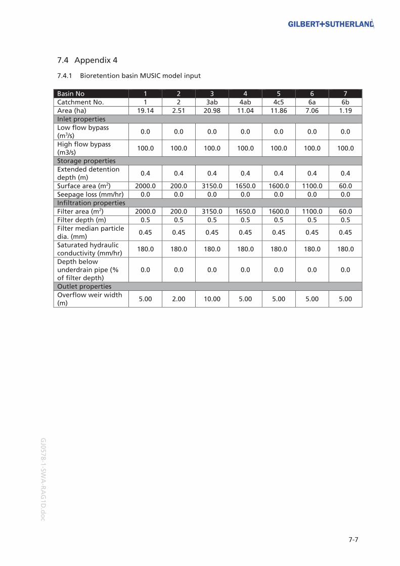
7-7
GJ0
57
8-1
-SW
A-R
AG
1D
.do
c
7.4 Appendix 4
7.4.1 Bioretention basin MUSIC model input
Basin No 1 2 3 4 5 6 7
Catchment No. 1 2 3ab 4ab 4c5 6a 6b
Area (ha) 19.14 2.51 20.98 11.04 11.86 7.06 1.19
Inlet properties
Low flow bypass (m3/s)
0.0 0.0 0.0 0.0 0.0 0.0 0.0
High flow bypass (m3/s)
100.0 100.0 100.0 100.0 100.0 100.0 100.0
Storage properties
Extended detention depth (m)
0.4 0.4 0.4 0.4 0.4 0.4 0.4
Surface area (m2) 2000.0 200.0 3150.0 1650.0 1600.0 1100.0 60.0
Seepage loss (mm/hr) 0.0 0.0 0.0 0.0 0.0 0.0 0.0
Infiltration properties
Filter area (m2) 2000.0 200.0 3150.0 1650.0 1600.0 1100.0 60.0
Filter depth (m) 0.5 0.5 0.5 0.5 0.5 0.5 0.5
Filter median particle dia. (mm)
0.45 0.45 0.45 0.45 0.45 0.45 0.45
Saturated hydraulic conductivity (mm/hr)
180.0 180.0 180.0 180.0 180.0 180.0 180.0
Depth below underdrain pipe (% of filter depth)
0.0 0.0 0.0 0.0 0.0 0.0 0.0
Outlet properties
Overflow weir width (m)
5.00 2.00 10.00 5.00 5.00 5.00 5.00

Finch Road, Canungra, SWA, Proposed Residential Subdivision
7-8
GJ0
87
0-1
-SW
A-R
AG
1F.d
oc

7-9
GJ0
57
8-1
-SW
A-R
AG
1D
.do
c
7.5 Appendix 5
7.5.1 MUSIC model water quality results

Finch Road, Canungra, SWA, Proposed Residential Subdivision
7-10
GJ0
87
0-1
-SW
A-R
AG
1F.d
oc

8-1
GJ0
57
8-1
-SW
A-R
AG
1D
.do
c
8) Attachment 1
8.1 Stormwater Management Plan

Stormwater Management Plan Proposed Residential Subdivision
Finch Road, Canungra Queensland
Prepared for: Auspacific Engineers
January, 2010

Finch Road, Canungra, Stormwater Management Plan, Proposed Residential Subdivision
ii
GJ0
57
8_SM
P_R
AG
1D
.do
c
Document control
Document: GJ0578_SMP_RAG1D.doc
Title: Stormwater Management Plan, Proposed Residential Subdivision, Finch Road, Canungra, Queensland
Project Manager:
Neil Sutherland
Author: Allan Genn
Client: Auspacific Engineers Pty Ltd
Client Contact: Rod Holmes
Client Reference:
Gilbert & Sutherland P/L ABN 56 077 310 840
Originating Office: Robina
Eastside 5/232 Robina Town Centre
Drive, Robina Q4226 PO Box 4115, Robina Q4230
Telephone 07 5578 9944 Facsimile 07 5578 9945
Also at Kawana and Brisbane
Synopsis: This management plan establishes responsibilities and procedures for the management of erosion, sediment and stormwater during the construction and operational phases of this project.
Revision History
Revision # Date Edition By Approved By
1 20/01/2010 AGG LJV NMS
Distribution
Revision Number
Distribution 1 2 3 4 5 6 7 8 9 10
Auspacific Engineers 8
G&S file and library 2

iii
GJ0
57
8_SM
P_R
AG
1D
.do
c
Summary
Gilbert & Sutherland Pty. Ltd (G&S) was commissioned by Auspacific Enginers Pty Ltd on behalf of Elbina Pty Ltd to prepare a Stormwater Assessment and Stormwater Management Plan (SWMP) for a proposed rural residential subdivision at Finch Road, Canungra. This Stormwater Management Plan provides procedures aimed at achieving site specific stormwater quality objectives during the construction and operational phases. Ideally it should be included in the contract documents for the earthworks, roadworks and drainage construction works in this project.

Finch Road, Canungra, Stormwater Management Plan, Proposed Residential Subdivision
iv
GJ0
57
8_SM
P_R
AG
1D
.do
c
Table of contents
1) Stormwater management plan ............................................................................................... 1-11.1 Objectives and implementation......................................................................................... 1-1
1.1.1 Objectives...................................................................................................................... 1-11.1.2 Implementation............................................................................................................ 1-1
1.2 SWMP structure................................................................................................................... 1-11.2.1 Site-specific objectives.................................................................................................. 1-1
1.3 General commitments ........................................................................................................ 1-21.4 Compliance.......................................................................................................................... 1-21.5 Definitions ........................................................................................................................... 1-31.6 Contact details .................................................................................................................... 1-3
2) Management of potential impacts – background and construction phase.......................... 2-12.1 Protection of SQIDS ............................................................................................................ 2-22.2 Construction phase dust management.............................................................................. 2-32.3 Construction phase sediment and erosion controls.......................................................... 2-42.4 Construction phase surface water monitoring on site ..................................................... 2-52.5 Construction phase surface water monitoring – permanent treatment measures......... 2-72.6 Construction phase contractor management.................................................................... 2-9
3) Management of potential impacts – on maintenance phase................................................ 3-13.1 Intent ................................................................................................................................... 3-13.2 Implementation .................................................................................................................. 3-13.3 On maintenance phase sediment and erosion controls ................................................... 3-23.4 On maintenance phase surface water monitoring ........................................................... 3-33.5 On maintenance phase maintenance ................................................................................ 3-5
4) Management of potential impacts – operational phase ....................................................... 4-14.1 Intent ................................................................................................................................... 4-14.2 Implementation .................................................................................................................. 4-14.3 Operational phase surface water monitoring................................................................... 4-24.4 Operational phase maintenance of treatment measures ................................................ 4-4
5) Administration of the SWMP................................................................................................... 5-15.1 Amendment of the SWMP ................................................................................................. 5-15.2 Incident management ........................................................................................................ 5-1

1-1
GJ0
57
8_SM
P_R
AG
1D
.do
c
1) Stormwater management plan
1.1 Objectives and implementation
1.1.1 Objectives
The primary objective of this SWMP is to provide mitigation measures to minimise the potential impacts of the development. Additionally, the SWMP provides information on specific site management issues relating to potential environmental impacts from the development during the construction and operational phases. The control measures detailed in this SWMP have been developed to minimise impacts on the environment and achieve the following objectives: • appropriate stewardship of natural resources, • protection of downstream flora and fauna habitats, • confirmation of the success of impact control measures by the means of monitoring during
the construction of each stage, • compliance with statutory requirements, and • preservation of the existing groundwater conditions.
1.1.2 Implementation
The management plan requires the Proponent to mitigate the potential environmental impacts associated with the construction of the subdivision works. It is intended that the SWMP will provide a set of performance criteria and guiding principles with which the engineering designs for the development will comply. The plans and specifications forming part of the construction contract for each stage should also include these performance criteria.
1.2 SWMP structure
This SWMP acknowledges the environmental impacts associated with the development and details strategies to mitigate them. Each control strategy is based upon proven environmental management methods and is presented as a commitment. The commitments made within this document will form the basis of future assessments, which will be made available to the Scenic Rim Regional Council for review.
1.2.1 Site-specific objectives
The stormwater quality objectives and environmental management strategies detailed in this SWMP are designed to comply with relevant laws and regulations while acknowledging the specific characteristics and localised environmental context of the site. The application of relevant legislation, guidelines and standards may necessitate specific consideration of unique or unusual natural and/or human factors in the local environment. Where necessary, variations to the relevant guidelines may be sought and, where approved, included in this SWMP. This SWMP includes tables detailing objectives and management strategies for both the construction and operational phases of the development. The party responsible for the implementation of the measures detailed is written on the table itself. The tables then detail the issue, the performance criteria, the implementation strategy, monitoring, auditing, reporting, failure identification and the corrective action. The detachable pages within each section detail the provisions of the SWMP. The format is presented below for reference purposes.

Finch Road, Canungra, Stormwater Management Plan, Proposed Residential Subdivision
1-2
GJ0
57
8_SM
P_R
AG
1D
.do
c
#.# Title
Person responsible This is the person or party who has accepted the responsibility of implementing the SWMP provisions detailed on this page
Issue The issue with which the table deals
Operational policy The operational policy or management objective that applies to the element.
Performance criteria Performance criteria (outcomes) for each element of the operation.
Implementation strategy
The strategies or tasks (to nominated operational design standards) that will be implemented to achieve the performance criteria
Monitoring The monitoring requirements which will measure actual performance (i.e. specified limits to pre-selected indicators of change).
Auditing The auditing requirements, which will verify implementation of, agreed construction and operation phase environmental management strategies and compliance with agreed performance criteria.
Reporting Content, timing and responsibility for reporting and auditing of monitoring results.
Identification of incident or failure
The circumstances under which the agreed performance criteria are unlikely to be met and environmental harm is likely to result.
Corrective action The action to be implemented in case a performance requirement is not reached and the party(s) responsible for action.
Commitment # A promise made by management. An objective of the tabular format is to allow for change and allow the management plan to be a working document. If items need altering, changes may be made (after the appropriate consultation with the statutory authorities) to the individual tables.
1.3 General commitments
Commitment 1 The Proponents undertake to comply with the environmental implementation strategy as contained within the approved Stormwater Management Plan (SWMP). Commitment 2 The Proponents undertake to fulfil all commitments made in this SWMP and to carry out their activities on the project site in accordance with relevant current statutory requirements and approved amendments
1.4 Compliance
Compliance with the provisions of this SWMP requires the objectives and management strategies contained herein to be both reasonable and achievable within the context of the approval(s) to which they relate. Incidents and/or failures that involve factors beyond the control of the responsible party(s) and the response and/or corrective actions taken by the responsible party(s) should be considered in assessing compliance with this SWMP.

1-3
GJ0
57
8_SM
P_R
AG
1D
.do
c
1.5 Definitions
In this SWMP the terms have the following meanings: SWMP means the approved Stormwater Management Plan and includes any amendments that may be approved from time to time; Development means the development of the site for the purposes of dwelling houses; SRRC means Scenic Rim Regional Council; Proponent means the person undertaking the development of the land and includes the person nominated by the Proponent as having the responsibility for implementing the provisions of the SWMP; QDERM means Queensland Department of Environment and Resource Management
1.6 Contact details
The following persons are responsible for the implementation of the management measures described in the individual tables of the SWMP. Contractor’s Site Manager The name and address of the Contractor and its representative will be notified to Council by the Consulting Engineer prior to the commencement of each contract/stage of the project. Consulting Engineer
Unless advised otherwise the Consulting Engineer is: Company: Auspacific Engineers Address: 3/20 Nerang Street Nerang Contact Details: Rod Holmes Phone: 55965377 Facsimile: 55963443 Environmental Consultant Unless advised otherwise the Environmental Consultant is: Company Gilbert & Sutherland Pty Ltd Address: Unit 5, Eastside 232 Robina Town Centre Drive PO Box 4115 Robina Q 4230 Contact Details: Mr Neil Sutherland Phone: 55789944 Facsimile: 55789945


2-1
GJ0
57
8_SM
P_R
AG
1D
.do
c
2) Management of potential impacts – background and construction phase The SWMP requires the Proponent to mitigate the potential environmental impacts associated with the construction of the subdivision works. Prior to commencement of construction in any stage, detailed erosion and sediment control plans, based on the requirements of this SWMP and the IEAust Guidelines, will be prepared and submitted to Council for approval. The estate should be developed in stages to minimise the potential for soil erosion and water pollution. This would enable the site to be progressively rehabilitated as the development proceeds. As soon as is practicable after the completion of the earthworks, the lots will be reseeded to establish a fast-growing cover crop which will minimise erosion and movement of sediment across and off the site. On steeper slopes and the road cuttings, it is likely that hydromulching and/or placing of hoop pine mulch will be required. Wherever possible the site will remain grassed and otherwise undisturbed until construction commences. Although no MUSIC modelling has been completed for the construction phase, it is evident that temporary sedimentation ponds and other sediment control measures should be installed during this phase. Prior to commencement of earthworks in any stage, temporary sedimentation ponds should be installed. The exact number, location and size will be determined at the detailed design stage concurrently with the development of the staging plan. All runoff from disturbed areas is to be collected by means of surface drains and diverted to a sedimentation pond. Where practicable, runoff from undisturbed areas should be diverted around disturbed areas and away from the sedimentation pond. The temporary sedimentation ponds may be removed when the site has been revegetated, after completion of the bulk earthworks. Other control measures such as (but not limited to) temporary sedimentation basins, silt fences and contour drains should be installed and maintained in accordance with recommendations contained in the ‘Soil Erosion and Sediment Control Engineering Guidelines for Queensland Construction Sites’ June 1996 by the Institution of Engineers, Australia (Queensland Division). Erosion and sediment control measures must be installed in disturbed areas during the building construction phase in accordance with the requirements of ‘Best Practice Guidelines for the Control of Stormwater Pollution from Building Sites’, Healthy Waterways, 2002. These measures should be maintained until landscaping has been completed and becomes established. The soils identified on the site are assessed as low to very low fertility soils. Nevertheless, it is considered that nutrient transport from the site during the construction phase should be minimised by implementation of appropriate control measures. The following detachable pages detail the provisions of this SWMP for the construction phase.

Finch Road, Canungra, Stormwater Management Plan, Proposed Residential Subdivision
2-2
GJ0
57
8_SM
P_R
AG
1D
.do
c
2.1 Protection of SQIDS
Bioretention basins are to be constructed in accordance with this SWMP and the engineering drawings to a stage that would allow the basin to function effectively. Before the basin becomes operational, the filter area is to be covered with geotextile filter fabric, loamy topsoil and turfed. When 80% of the homes in the device’s catchment have been completed, the developer will have the final landscaping completed in accordance with the approved landscape plans. Council will agree to bond such uncompleted landscaping works to enable the release of the signed and sealed survey plans on a stage by stage basis.

2-3
GJ0
57
8_SM
P_R
AG
1D
.do
c
2.2 Construction phase dust management.
Person responsible Contractor’s Site Manager.
Issue Minimisation of movement of dust offsite.
Operational policy To achieve acceptable air quality standards through the control of the movement of dust offsite from site works.
Performance criteria The target level for complaints by nearby residents is no more than one in any seven day period. Ambient air quality should not deteriorate by more than 30% over a period of seven consecutive days. Dust deposition at any nearby residence should not exceed 100mg/m2/day.
Implementation strategy
The minimisation of the movement of dust offsite will be achieved through the following onsite practices: All permanent bunds and reshaped areas will be revegetated within 10 days after completion of earthworks (including excavation and backfilling of services trenches). Stockpiling onsite will be minimised where possible. An onsite water cart will be available at all times. The site will be watered daily and additional watering will be conducted during high-risk times such as high winds and low rainfall and after receipt of complaints. All dust creating activities to cease if wind speed exceeds 10m/sec. Contractors’ staff to be trained to implement dust minimisation measures.
Monitoring Daily inspections will be carried out to verify that dust mitigation measures are being implemented. Dust monitoring will be conducted upon receipt of complaints by residents. If dust monitoring is to take place, the following will occur: Temporary dust deposition gauges will monitor the movement of dust offsite at the nearest residences adjacent to the proposed stages and within the predominant wind directions. Monitoring will be undertaken in accordance with AS 3580.10.1(1991).
Auditing Management to examine the complaints register weekly and review corrective action taken.
Reporting The contractor to notify QDERM of a possible environmental nuisance on receipt of 3 or more dust complaints in any 24 hour period. Receipts will be provided to SRRC upon request. Complaints by residents are to be recorded in a Complaints Register and notified to SRRC.
Identification of incident or failure
Any dust-related complaints by residents will indicate a failure of the dust control measures.
Corrective action Locate the source of the dust and implement the following measures: Apply water sprays to vegetation Cover or water exposed areas If dust persists, cease the dust creating activities. All dust complaints to be addressed in consultation with council officers.
Commitment 3 Dust generated during the construction of the subdivision works will be managed to ensure that dust movement offsite is controlled.

Finch Road, Canungra, Stormwater Management Plan, Proposed Residential Subdivision
2-4
GJ0
57
8_SM
P_R
AG
1D
.do
c
2.3 Construction phase sediment and erosion controls
Person responsible Contractor’s Site Manager, Consulting Engineer
Issue Sediment and Erosion Controls.
Operational policy To prevent the displacement of sediment and soil across and offsite.
Performance criteria Offsite discharges to comply with requirements for suspended sediments as detailed in Section 2.5 of the SWMP. No visual indication of erosion on stages under construction, including evidence of rilling (an indicator of sheet erosion).
Implementation strategy
Prior to commencement of construction in any stage, detailed erosion and sediment control plans shall be submitted to and approved by SRRC. Erosion and sediment control devices shall be installed prior to commencement of work in each stage in accordance with the approved plans and to the reasonable satisfaction of SRRC. Temporary erosion measures (eg. silt fences) are to be employed onsite during construction where reasonably deemed necessary by SRRC from an assessment of slope and soil type. Such measures should be in accordance with the recommendations in the IE Aust. Qld. Soil Erosion and Sediment Control Guidelines. Stockpiled soil should be stored/bunded in a manner to prevent soil being washed offsite (i.e. bunding where necessary.) Outside the construction area of each stage existing surface water conditions should be maintained wherever possible.
Monitoring Carry out visual inspections weekly and after rainfall events to ensure that erosion measures are in place and operational to suit the activities taking place at the time. Surface water quality to be monitored monthly (refer to the Section titled ‘Surface Water Monitoring’ which details monitoring of surface water and stormwater quality).
Auditing Visual inspections to be carried out monthly and after rainfall events to verify that control measures are in place and properly maintained.
Reporting Reporting only required if insufficient sediment and erosion measures are identified.
Identification of incident or failure
Signs of erosion on site. Damaged or failed erosion control devices. Falling stormwater quality as identified by Environmental Contractor. Build-up of sediment.
Corrective action Apply remedial measures to improve sediment and erosion measures, for example: silt fences, shake down areas.
Commitment 4 Best management practices will be implemented into work practices throughout the construction of the subdivision works to minimise erosion and sediment transport offsite.

2-5
GJ0
57
8_SM
P_R
AG
1D
.do
c
2.4 Construction phase surface water monitoring on site
Person responsible Contractor’s Site Manager, Environmental Consultant
Issue Surface water controls on site – temporary sedimentation ponds.
Operational policy To maintain stormwater quality conditions of runoff during the construction phase.
Performance criteria All water discharged from the site during the construction phase should comply with the following criteria:
Water Quality Parameter
Release Criteria Criteria Type
pH 6.5 – 9.0 Range
Turbidity 50NTU Maximum
Dissolved Oxygen >6mg/L Minimum
Suspended Solids <50mg/L Maximum
Total N <0.75mg/L Maximum
Total P <0.10mg/L Maximum
Oil and Grease No visible slicks Maximum
Litter and Trash None visible
Implementation strategy
Stormwater control should be achieved by directing as much runoff as practicable from disturbed areas to temporary sedimentation ponds. ‘Clean’ runoff from undisturbed areas should be diverted around disturbed areas if possible. All samples must be analysed at a NATA registered laboratory for the indicators listed in ‘Monitoring’ below.
Monitoring Surface water monitoring during construction should be conducted in all temporary sedimentation basins for the parameters listed above. Flow rates are to be estimated and recorded at the time of sampling. Sampling frequency is to be monthly and during the first rainfall event (>25mm in any 24hr period) each month. Sampling locations are to be selected in consultation with Council Officers to suit the works in progress. Daily visual surveillance of water bodies for changes in conditions.
Auditing The Consulting Engineer to audit stormwater quality results to verify that all discharges comply with the performance criteria above.
Reporting Result sheets to be compiled for monitoring results. All results to be kept on site for inspection by local and state government officers at all times. Monthly reports to SRRC including raw data, a results summary and a discussion comparing results with baseline values and SEQRMS guidelines.
Identification of incident or failure
Degradation of surface water quality (i.e. Suspended Solids) at the monitoring points to below the levels specified in ‘Performance Criteria’ above prior to discharge. Visible changes in water body conditions.

Finch Road, Canungra, Stormwater Management Plan, Proposed Residential Subdivision
2-6
GJ0
57
8_SM
P_R
AG
1D
.do
c
Corrective action If the test result for any parameter fails to meet the performance criteria, then weekly monitoring shall commence and continue until the recorded value/s meet the performance criteria. If a pH is detected outside the criteria range, then such waters should be contained, and the pH adjusted to within the range of 6.5 to 9.0 prior to release. If total suspended solids exceed the water quality criteria for this parameter, then water may need to be contained on site for a period sufficient to allow suspended solids to settle out prior to release, or settling should be aided by dosing with flocculation agents at the rate recommended by the manufacturer (for example Gypsum at dose rate of 30kg/100m3). Erosion control devices should be immediately inspected and cleaned if necessary. Additional devices should be installed if a need is detected to prevent future breaches of the suspended solids criteria. The placement of stockpiles and management of disturbed areas should be reviewed with regard to sediment and silt control.
Commitment 5 The Proponent will take all reasonable steps to ensure that all waters discharged from the site meet the performance criteria set out above.

2-7
GJ0
57
8_SM
P_R
AG
1D
.do
c
2.5 Construction phase surface water monitoring – permanent treatment measures
Person responsible Contractor’s Site Manager, Consulting Engineer, Environmental Consultant
Issue Surface water controls, permanent treatment measures.
Operational policy To maintain water quality condition of receiving waters during the construction phase.
Performance criteria All water discharged from the site during the construction phase should comply with the following criteria:
Water Quality Parameter
Release Criteria Criteria type
pH 6.5-9.0 Range
Suspended Solids <50mg/L Maximum
Dissolved Oxygen (field measured)
>6.0mg/L Minimum
Total N <0.75mg/L Maximum
Total P <0.10mg/L Maximum
Oil and Grease No visible slicks Maximum
Litter and Trash None visible
These performance criteria may be adjusted upon submission of suitable background data and justification of the use of ‘<10% above background levels’ for relevant parameters. Any amendment to the performance criteria must receive written approval by SRRC prior to alteration of the approved SWMP.
Implementation strategy
Surface water samples to be collected during the first rainfall event (>25mm in 24 hours) each month from the approved monitoring points and analysed at a NATA registered laboratory. Monitoring results should be reviewed after 6 months and sampling frequency revised in consultation with Council Officers. Stormwater control should be achieved by directing as much runoff as practicable from disturbed areas to the temporary control measures. ‘Clean’ runoff from undisturbed areas should be diverted around disturbed areas if possible.
Monitoring Surface water monitoring during construction should be conducted at the monitoring points for the parameters shown above. Flow rates are to be estimated and recorded at the time of sampling. Sampling frequency is to be after the first rainfall event (>25mm in 24hours) each month. Daily visual surveillance of water bodies for changes in conditions.
Auditing The consulting engineer to audit stormwater quality results to verify all discharges comply with the performance criteria.

Finch Road, Canungra, Stormwater Management Plan, Proposed Residential Subdivision
2-8
GJ0
57
8_SM
P_R
AG
1D
.do
c
Reporting Results sheets to be compiled for monitoring results relating to water quality of water bodies. All results to be kept on site for inspection by local and state government officers at all times. Monthly reports to SRRC including raw data, a results summary and a discussion comparing results with baseline values and SEQRMS guidelines.
Identification of incident or failure
Degradation of surface water quality at the monitoring points to below the levels specified in ‘Performance Criteria’ above prior to discharge. Apparent visual changes in water body conditions.
Corrective action Locate the source of the contaminant. Take all possible actions to contain and control the contaminant. Investigate the cause of the contamination and take action to prevent a recurrence. If the test result for any parameter fails to meet the performance criteria, then weekly monitoring shall commence and continue until the recorded value/s meets the performance criteria. For example: If total suspended solids exceed the stormwater quality criteria for this parameter, then water may need to be contained on site for a period sufficient to allow suspended solids to settle out prior to release, or settling shall be aided by dosing with flocculation agents at the rate recommended by the manufacturer. Erosion control devices should be immediately inspected and cleaned if necessary. Additional devices should be installed if a need is detected to prevent future breaches of the suspended solids criteria. The placement of stockpiles and management of disturbed areas should be reviewed with regard to sediment and silt control. If Total N levels are high, check upstream stormwater quality. Check fertiliser application rates on landscaping work on site and adjust as required. If Total P levels are high, check effluent disposal practices upstream. Check fertiliser rates on landscaping work on site and adjust as required. If Oil and Grease levels are high, locate the source of the contamination and clean up source and contaminated waters in consultation with Council officers.
Commitment 6 Surface water quality should be maintained during the construction of the subdivision works in accordance with the criteria detailed above.

2-9
GJ0
57
8_SM
P_R
AG
1D
.do
c
2.6 Construction phase contractor management
Person responsible Consulting Engineer
Issue Contractor management.
Operational policy To ensure the proponent’s duty of care is met by ensuring the Contractor is aware of his responsibilities under the terms of the SWMP and the QDERM.
Performance criteria Contractor is fully aware of their responsibilities under the terms of the SWMP.
Implementation strategy
Review of the SWMP and the construction phase contracts by the proponent. Periodic checks to be made by an independent Environmental Consultant. Training for construction staff in implementation of SWMP provisions.
Monitoring Weekly site inspections to be carried out.
Auditing Inspections will be carried out monthly during the construction phase by an Environmental Consultant for every stage of development.
Reporting Full details to be available to the contractor together with suggested corrective actions if required.
Corrective action To be detailed at the time.
Commitment 7 A proactive program of contractor management will be implemented.


3-1
GJ0
57
8_SM
P_R
AG
1D
.do
c
3) Management of potential impacts – on maintenance phase
3.1 Intent
This part of the SWMP specifies those matters which must be complied with by the Proponent during the ‘on-maintenance period’, being the period after construction but before Scenic Rim Regional Council assumes responsibility for the subdivision works. The Proponents’ obligations in this Section of the SWMP conclude at the end of the maintenance period for each stage. The ‘on- maintenance’ periods for the various portions of the works shall be as follows: • bioretention basins & wetlands 12 months • all other works 6 months It also details how the development design will contribute to stormwater treatment and water quality maintenance during the operational phase (or life) of the development.
3.2 Implementation
At the completion of the construction of the development’s civil works, the GPT’s should be cleaned out to become part of the permanent stormwater quality control treatment train.

Finch Road, Canungra, Stormwater Management Plan, Proposed Residential Subdivision
3-2
GJ0
57
8_SM
P_R
AG
1D
.do
c
3.3 On maintenance phase sediment and erosion controls
Person responsible Contractor’s site manager, consulting engineer.
Issue Sediment and erosion controls.
Operational policy To prevent the displacement of sediment and soil across and offsite.
Performance criteria Offsite discharges to comply with requirements for suspended sediments as detailed in Section 3.4 of the SWMP.
Implementation strategy
Temporary erosion and sediment control devices shall be maintained in an operational state during the maintenance period.
Monitoring Temporary erosion control measures are to be inspected monthly and after rainfall events. Permanent stormwater quality control structures (GPT’s, basins etc.) are to be inspected monthly and after rainfall events.
Auditing Quarterly inspections to be carried out by an independent Environmental Consultant.
Reporting Reporting only required in the event of failure of the sediment and erosion control measures.
Identification of incident or failure
Signs of erosion on site Build up of sediment Falling stormwater quality
Corrective action Repair temporary sediment and erosion control measures. Check permanent measures for build up of sediment and clean out as necessary.
Commitment 8 Erosion and sediment control devices will be maintained during the on-maintenance period until the risk of soil erosion and sediment transport is considered negligible.

3-3
GJ0
57
8_SM
P_R
AG
1D
.do
c
3.4 On maintenance phase surface water monitoring
Person responsible Contractor’s Site Manager, Environmental Consultant.
Issue Surface water monitoring in new permanent water bodies.
Operational policy To establish stable surface water conditions and verify that development management is appropriate.
Performance criteria All water discharged from the site should comply with the following criteria:
Water Quality Parameter
Release Criteria Criteria type
pH 6.5-9.0 Range
Suspended Solids <50mg/L Maximum
Dissolved Oxygen (field measured)
>6.0mg/L Minimum
Total N <0.65mg/L Maximum
Total P <0.10mg/L Maximum
Oil and Grease No visible slicks Maximum
Chlorophyll-a 10μg/L Maximum
Algal cell count 10,000cells/mL Maximum
Faecal coliforms 1,000cfu/100mL Maximum
These performance criteria may be adjusted upon submission of suitable background data and justification of the use of ‘<10% above background levels’ for relevant parameters. Any amendment to the performance criteria must receive written approval by SRRC prior to alteration of the approved SWMP.
Implementation strategy
Surface water entering and exiting the development shall be monitored at the approved monitoring points during the ‘On-maintenance’ period. Surface water monitoring shall be undertaken at the discharge points from the development stages until stable water quality criteria have been established. Monitoring will also be undertaken during flood events where practicable. This monitoring will allow water quality comparisons to be made.
Monitoring Surface water monitoring for all parameters will be conducted monthly at all monitoring points. To revert to construction phase provisions if problems are identified. If problems are identified, laboratory analysis at a NATA registered laboratory for the parameters listed above until such a time as SRRC is satisfied that the Proponent’s duty of care under the QDERM has been discharged. These provisions will conclude at the end of the ‘on maintenance’ period.
Auditing The Proponent to audit water quality results quarterly to verify that discharges comply with the performance criteria.

Finch Road, Canungra, Stormwater Management Plan, Proposed Residential Subdivision
3-4
GJ0
57
8_SM
P_R
AG
1D
.do
c
Reporting of monitoring results
Monitoring test results are to be compiled on monthly result sheets. Monthly reports containing raw data and an interpolation sheet to be sent to SRRC. Results to be available at all times.
Identification of incident or failure
Fall in surface water quality at the environmental monitoring points.
Corrective action Identify reason for deterioration in surface water quality to identify if it is linked to the development. Take necessary steps to address the problem such as improved temporary sediment and erosion controls.
Commitment 9 Subdivision works will be maintained during the maintenance period to ensure surface water quality complies with the water quality criteria detailed above.

3-5
GJ0
57
8_SM
P_R
AG
1D
.do
c
3.5 On maintenance phase maintenance
Person responsible Contractor’s Site Manager, Consulting Engineer.
Issue Maintenance
Operational policy To maintain the stormwater quality control structures to ensure adequate performance during the maintenance period.
Performance criteria The control measures are maintained and operational.
Implementation strategy
Ensure inlets and outlets are not blocked and are structurally stable. All waste to be disposed of at council approved waste facilities.
Monitoring Monthly inspection of control structures during the maintenance period. Any recurring problems with the control structures to be rectified during the maintenance period. Structures also to be inspected following major rainfall events.
Auditing The Proponent to carry out quarterly inspections to verify that the stormwater quality control structures are properly maintained by the contractor.
Reporting of monitoring results
Record inspection details. Record details of all maintenance activities (including volume of silt removed from each GPT or other control structure) and include in monthly reports to SRRC. Results to be available to QDERM at all times.
Identification of incident or failure
Blockage of stormwater system. Re-entrainment of trapped sediments. Deterioration of water quality within or downstream of control structure.
Corrective action Clean or maintain stormwater control structure as appropriate. Take necessary steps to address the problem to prevent a recurrence.
Commitment 10 Stormwater quality control structures will be adequately maintained during the maintenance period to ensure continued performance.


4-1
GJ0
57
8_SM
P_R
AG
1D
.do
c
4) Management of potential impacts – operational phase
4.1 Intent
This part of the SWMP specifies those matters that must be complied with by SRRC after it assumes responsibility for the subdivision works.
4.2 Implementation
Permanent stormwater quality control structures are to be monitored and maintained as detailed in the following tables.

Finch Road, Canungra, Stormwater Management Plan, Proposed Residential Subdivision
4-2
GJ0
57
8_SM
P_R
AG
1D
.do
c
4.3 Operational phase surface water monitoring
Person responsible Scenic Rim Regional Council
Issue Surface water monitoring.
Operational policy To verify that stable surface water conditions are maintained.
Performance criteria All water discharged from the site will comply with the following criteria:
Water Quality Parameter
Release Criteria Criteria type
pH 6.5-8.0 Range
Suspended Solids <15mg/L Maximum
Dissolved Oxygen (field measured)
>6.0mg/L Minimum
Total N <0.65mg/L Maximum
Total P <0.10mg/L Maximum
Oil and Grease No visible slicks Maximum
Chlorophyll-a 10μg/L Maximum
Algal cell count 10,000cells/mL Maximum
Faecal coliforms 1,000cfu/100mL Maximum
These performance criteria may be adjusted upon submission of suitable background data and justification of the use of ‘<10% above background levels’ for relevant parameters. Any amendment to the performance criteria must receive written approval by SRRC prior to alteration of the approved SWMP.
Implementation strategy
Surface water entering and exiting the development shall be monitored at the approved monitoring points during the operational phase of the development. Monitoring will also be undertaken during flood events where practicable. This monitoring will allow water quality comparisons to be made.
Monitoring Surface water monitoring will be conducted for all parameters quarterly for 12 months then half yearly. To revert to construction phase provisions if problems are identified. If problems are identified, laboratory analysis at a NATA registered laboratory for Suspended Solids, Total N, and Total P until such a time as SRRC determines the cause of the problem and rectifies it.
Auditing Council to audit water quality results quarterly to verify that discharges comply with the performance criteria.
Reporting of monitoring results
Monitoring test results are to be compiled annually. Annual reports containing raw data and an interpretation to be made available to all persons on request. Results to be available at all times.
Identification of incident or failure
Fall in surface water quality at the environmental monitoring points.

4-3
GJ0
57
8_SM
P_R
AG
1D
.do
c
Corrective action Identify reason for deterioration in surface water quality to identify if it is linked to the development and/or the treatment structures. Take necessary steps to address the problem such as a public education program regarding fertilisers and other nutrients.

Finch Road, Canungra, Stormwater Management Plan, Proposed Residential Subdivision
4-4
GJ0
57
8_SM
P_R
AG
1D
.do
c
4.4 Operational phase maintenance of treatment measures
Person responsible Scenic Rim Regional Council
Issue Operation and maintenance of the treatment measures.
Operational policy To maintain the stormwater quality control structures to ensure adequate performance during the operational period.
Performance criteria The control measures are maintained and operational. Pollutant concentration of stormwater released from the treatment system to satisfy the quality criteria set out in Section 4.3.
Implementation strategy
Ensure inlets and outlets are not blocked. Ensure that sediment accumulation does not impair operation of GPT.
Monitoring Water sampling to be carried out according to Section 4.3. If elevated levels are found for any parameter, commence weekly sampling and testing for the parameter concerned and if possible examine the composition/constituents of the pollutant. Establish complaints register and record details of complaints. Inspect control structures after rainfall events. These inspections are to be recorded.
Auditing SRRC to carry out quarterly inspections to verify that monitoring has been carried out and that action has been implemented if required to correct any shortcomings.
Reporting of monitoring results
Monthly reports to SRRC. Record details of all maintenance activities. Results to be available to QDERM at all times.
Identification of incident or failure
Water quality of outflow fails to meet the release criteria. Complaints from residents about odours or increased mosquito numbers.
Corrective action Clean or maintain stormwater control structure as appropriate.

5-1
GJ0
57
8_SM
P_R
AG
1D
.do
c
5) Administration of the SWMP
5.1 Amendment of the SWMP
The proponent may make application to SRRC to amend the provisions of this SWMP. The application shall: a. be in writing; b. specify the provisions of the SWMP to which the application relates; and c. state how the proposed amendment(s) achieve the objectives of the provisions to which the
amendment(s) relate. SRRC shall approve the amendment(s) where SRRC is satisfied acting reasonably that the proposed amendment(s) achieve the objective of the provisions to which the amendment(s) relates.
5.2 Incident management
The Proponent and any person appointed by the Proponent as having responsibility for a control strategy set out in this SWMP have clearly defined responsibilities under the Environment Protection Act 1994 to report any incidents likely to cause material or serious environmental harm.