attachment a design criteria package corrective …
TRANSCRIPT

ATTACHMENT A DESIGN CRITERIA PACKAGE
Corrective Action Plan – Version 2
http://www.miamigov.com/CITP/Pages/ProcurementOpportunities/RFP_WagnerCreekSeyboldCanal.html

Technical Specifications
HEALTH, SAFETY, AND EMERGENCY RESPONSE
01 05 01 - 1
SECTION 01 05 01 HEALTH, SAFETY, AND EMERGENCY RESPONSE
PART 1 GENERAL
WORK INCLUDED
A. Design-Builder shall assume portions of the work to contain contaminant concentrations that exceed background concentrations in soil, groundwater, and sediment at locations and depths as specified in the scope of work.
B. Construction/remediation activities may place Design-Builder’s personnel, other people present for work at site, and public in potentially hazardous situations due to nature of contaminants present on job site. Due to potential for serious incidents, special emphasis must be placed upon health and safety considerations for all on-site personnel, public, and surrounding environment. Site activities shall involve work exposure to potentially contaminated materials. It shall be responsibility of Design-Builder to provide all facilities, equipment, monitoring instruments, materials and personnel necessary to protect all onsite personnel and off-site receptors from physical injury and potential adverse health effects which could result from exposure to chemical hazards which are on site.
C. Design-Builder is responsible for implementation and enforcement of Site health and safety requirements along with emergency response requirements, and take necessary precautions and provide protection for following:
Personnel working on or visiting Project site, irrespective of employer.
Work and materials or equipment to be incorporated in Work area on-or off-site.
Other property at or adjacent to Project site.
Public exposed to job related operations or potential release of contaminated materials.
D. Design-Builder is responsible for initiating, maintaining, and supervising safety precautions and programs in connection with Work. Design-Builder shall take necessary precautions for safety of employees on Project site and other persons and organizations who may be affected by Project.
E. Design-Builder shall be directly responsible for health and safety of their employees and shall not rely on support and services that are in place on the Owner’s job site. In event of any and all issue/emergency, Design-Builder shall address issue/emergency with their personnel and support systems and provide appropriate notification to the Owner.
F. Design-Builder’s duties and responsibilities for safety in connection with Work shall continue until such time as Work is complete and the Owner has issued notice to Design-Builder that Work is complete.

HEALTH, SAFETY, AND EMERGENCY RESPONSE
01 05 01 - 2
G. Design-Builder shall develop and implement written Health, Safety, and Emergency Response Plan (HSERP) which, at minimum, meets requirements of this section and complies with applicable federal, state, local and site regulations. HSERP shall be the agreed upon method for implementation and enforcement of Site safety, health, and emergency response requirements.
H. The Design-Builder’s HSERP shall comply with all provisions of these specifications and all personnel on site will be required to sign and acknowledge the HSERP.
I. If the Design-Builder does not have capability to prepare HSERP, the Design-Builder shall employ consultants with appropriate capabilities.
J. HSERP shall be submitted and approved by the City for approval before any work on job site can begin.
K. Approved HSERP, complete with all comments addressed and appropriate revisions, will be made part of Contract Documents.
SUBMITTALS
A. Submit copies of HSERP to the Owner in accordance with provisions listed in these specifications.
B. Submit copy of the Design-Builder’s Corporate Safety Manual.
C. Submit copies Safety training records of all staff employed on-site.
D. No Work on-site shall proceed until HSERP has been submitted to and approved by the Owner.
E. Design-Builder shall certify to the Owner by weekly submittal from the Design-Builder’s Health and Safety Officer that the Design-Builder is in compliance with HSERP.
F. The Design-Builder shall be responsible for submitting name, qualifications, training records, and experience of personnel required above in accordance with following:
Health and Safety Coordinator (HSC) information shall be submitted to the Owner at Pre-Work conference and before any changes are made.
Health and Safety Officer (HSO) information shall be submitted to the Owner at Pre-Work conference and before any changes are made.
Safety Technician (ST) information shall be submitted to the Owner at Pre-Work conference and before any changes are made.
REGULATORY REQUIREMENTS
A. HSERP shall meet all requirements of this section and applicable requirements including but not limited to these contained in publications listed below.
HEALTH, SAFETY, AND EMERGENCY RESPONSE
01 05 01 - 3
CFR:
a. 29 CFR 1920, Occupational Safety and Health Administration (OSHA) Standards for General Industry.
b. 29 CFR 1910.120, OSHA Standards, "Hazardous Waste Operations and Emergency Response".
c. 29 CFR 1910.134, OSHA Standards, "Respiratory Protection".
d. 29 CFR 1910.1000 through 1910.1048, OSHA Standards, "Air Contaminants - Permissible Exposure Limits".
e. 29 CFR 1910.1200, OSHA Standards, "Hazard Communication".
f. 29 CFR 1926, OSHA Standards, "Construction Industry".
g. 29 CFR 1926.59, OSHA Standards, "Hazard Communication Standard for Construction Industry".
h. 29 CFR 1926.1118, Inorganic Arsenic.
i. 40 CFR 260, Hazardous Waste Management System: General.
j. 40 CFR 261, Identification and Listing of Hazardous Wastes.
k. 40 CFR 263, Standards Applicable to Transporters of Hazardous Wastes.
l. 40 CFR 264, 265, 270, and 271, Corrective Action for Solid Waste Management Units at Hazardous Waste Management Facilities, Proposed Rule.
m. 49 CFR 171, Hazardous Materials Regulations: General Information, Regulations, and Definitions.
n. 49 CFR 172, Hazardous Materials Tables and Hazardous Materials Communications Regulations.
o. 49 CFR 173, Shippers - General Requirements for Shipments and Packaging.
p. 49 CFR 178, Shipping Container Specifications.
q. Other Agencies Minimum Requirements:
National Institute for Occupational Safety and Health (NIOSH).
OSHA.
U.S. Coast Guard.
U.S. Environmental Protection Agency (EPA).

HEALTH, SAFETY, AND EMERGENCY RESPONSE
01 05 01 - 4
U.S. Army Corps of Engineers.
Florida Department of Environmental Protection
Miami-Dade County.
City of Miami.
r. American National Standards Institute (ANSI):
ANSI Z358.1 - Emergency Eye Wash and Shower Equipment.
ANSI Z88.2 - Practices for Respiratory Protection.
ANSI G-7.11 - Commodity Specification for Air.
s. Comply with applicable laws and regulations of any public body having jurisdiction for safety of persons or property.
B. Other Publications:
American Conference of Governmental Industrial Hygienists (ACGIH) - Threshold Limit Values for Chemical Substances and Physical Agents and Biological Exposure Indices, current issue.
(1985) Occupational Safety and Health Guidance Manual for Hazardous Waste Site Activities.
RESPONSIBILITIES
A. The Design-Builder shall provide services of Health and Safety Coordinator, Health and Safety Officer and Safety Technicians.
Health and Safety Coordinator: Designated Health and Safety Coordinator (HSC) shall be certified in comprehensive practice of industrial hygiene by American Board of Industrial Hygiene (ABIH) and have minimum of 5 years’ experience in field of construction and hazardous waste or related chemical industries. HSC must have working knowledge of state and federal occupational safety and health regulations, and demonstrable experience in air monitoring and in development of personal protective equipment programs for working in potentially toxic atmospheres. HSC shall be Certified Industrial Hygienist (CIH) or Certified Safety Professional (CSP).
a. HSC shall be responsible for development and implementation of HSERP. All site-specific health and safety training shall be approved by HSC, and initial site-specific training shall be conducted by HSC. HSC will not be required to be present at site for entire duration of project, but must be available for consultation and/or assistance at all times throughout remedial activities.
HEALTH, SAFETY, AND EMERGENCY RESPONSE
01 05 01 - 5
b. HSO shall be assigned to site on full-time basis and report directly to HSC on matters pertaining to site health and safety, air monitoring and public protection. HSC will be responsible for day-to-day implementation of HSERP and Atmospheric/Air Monitoring. The acceptable qualifications for the SSO will be as follows:
A degree in Occupational Safety and Health from an ABET-accredited college;
Either a Certified Safety Professional (CSP) or Certified Industrial Hygienist (CIH) designation;
A Safety Trained Supervisor (STS) accreditation from the Board of Certified Safety Professionals plus 5 years of relevant work experience or;
A resume that has been approved by the Owner.
Safety Technician: Safety Technician (ST) must have 1 year of related experience and basic understanding of current health and safety regulations. In addition to site-specific training given by HSC, ST shall have had additional training in personal protective equipment and air monitoring instruments. ST also must have current certification in First Aid and CPR (American Red Cross or equivalent).
a. Each crew working in potentially hazardous areas shall include at least one Safety Technician. ST shall be responsible for compliance with HSERP. ST shall report directly to HSO on all matters relating to on-site health and safety matters including noncompliance with HSERP.
HSERP REQUIREMENTS
A. Because this Contract will require work in hazardous environment, the Design-Builder shall develop and implement comprehensive Health, Safety, and Emergency Response Plan (HSERP) to ensure adequate protection for all on-site personnel, visitors and surrounding community.
B. HSERP shall be developed and implemented by the Design-Builder’s HSC. Day-to-day enforcement of HSERP will be provided by the Design-Builder’s HSO in conjunction with the Design-Builder’s ST(s). Formal statement of qualifications and responsibilities of the Design-Builder’s health and safety personnel shall be included in HSERP. Requirements described herein shall be used as minimum outline description of HSERP. HSERP shall be site-specific and incorporate assessment of hazards associated with work. HSERP shall address not only potential chemical hazards but also potential physical and biological hazards associated with performance of work.
C. HSERP shall address following minimum subject areas in accordance with 29 CFR 191O.120(b)(4)(ii):

HEALTH, SAFETY, AND EMERGENCY RESPONSE
01 05 01 - 6
Site Description/History/Evaluation.
Health and Safety Organization (responsibilities, qualifications and chain of command).
Work Zones.
Site Control.
Hazard Assessment.
Training.
Medical Surveillance.
Atmospheric/Air Monitoring.
Standard Operating Safety Procedures, Engineering Controls and Work Practices.
Personal Protective Equipment.
Personnel Hygiene and Decontamination.
Equipment and Material Decontamination.
Emergency Equipment and First Aid Requirements.
Emergency Response/Contingency Plans and Procedures.
Heat/Cold Stress Monitoring.
Hazard Communication Program including (MSDSs).
Accident Prevention Plan.
Cutting and Welding Procedures (including hot work permits).
Spill Control Provisions.
Water/Boat Safety.
Drinking Water and Supplies.
HSERP ELEMENTS AND EXECUTION
A. Site Description History/Evaluation: The Design-Builder shall briefly describe site, history, any evaluations completed with dates and type of contamination. This section should not be more than one page.
B. Health and Safety Organization: The Design-Builder shall describe health and safety organization for project including identification of key personnel, their

HEALTH, SAFETY, AND EMERGENCY RESPONSE
01 05 01 - 7
resumes/professional profiles, their responsibilities, and administrative flowchart or procedures for identifying problems and taking corrective actions.
HEALTH, SAFETY, AND EMERGENCY RESPONSE
01 05 01 - 8
C. Work Zones:
The Design-Builder shall be responsible for establishing work zones on job site. Work zones may be fixed locations throughout duration of job or may be adjusted as area of work activity changes. Work zones shall be defined as follows:
a. Exclusion Zone: Initially, Exclusion Zone (EZ) will include all potentially contaminated areas of site where work is to be performed. The Design-Builder may change Exclusion Zone with approval of the Design-Builder during progress of work; requests for such change shall be in writing and include justification.
b. Contamination Reduction Zone: Contamination Reduction Zone (CRZ) is transition area between contaminated work area and "clean area". Distance between Exclusion Zone and Support Zone provided by CRZ, together with decontamination of works and equipment should limit transfer of potential contaminants into "clean areas". Contractor shall require personnel entering CRZ to wear personal protective equipment prescribed for working in EZ as specified in the Design-Builder’s HSERP.
c. Support Zone: Support Zone shall be utilized by the Design-Builder for administrative and other support functions. Examples of equipment and facilities that will be located in this area include, but are not limited to, lunch and break areas, supplies and equipment storage, parking, the Design-Builder offices and maintenance facilities. Personnel may wear normal work clothing in this zone. Potentially contaminated clothing, equipment and materials shall not be allowed in this area prior to proper decontamination in CRZ.
The Design-Builder shall mark outer limits of Exclusion Zone with high visibility markers or flagging.
The Design-Builder shall be responsible for establishing means of communication between work zones, and for workers within same zone. This means of communication shall be documented in HSERP.
The Design-Builder shall be responsible for security within each established work zone.
The Design-Builder is reminded that although work zones shall be established, possibility for exposure to contamination exists anywhere on job site depending upon activity.
D. Site Control:
The Design-Builder shall establish system to control access to job site. This system shall be incorporated into layout of work zones and shall ensure that only authorized persons enter site.
HEALTH, SAFETY, AND EMERGENCY RESPONSE
01 05 01 - 9
The Design-Builder shall keep daily sign in/out logs for all ''work zones". Daily sign in/out logs shall be submitted to the Design-Builder weekly with certification statement see Article Submittals of this specification for additional details.
E. Hazard Assessment:
Purpose of hazard assessment is to provide information necessary for selecting personal protective equipment, establishing air monitoring requirements and determining health and safety procedures necessary to protect all on-site personnel, environment and public.
a. Qualitative evaluation of chemical hazards shall be based upon following:
Nature of potential contaminants.
Locations of potential contaminants project site.
Concentrations of contaminants.
Potential for personnel/public exposure during various site activities.
Effects of potential contaminants on human health.
Physical work area (water and railroad).
b. Biological Hazards: The Design-Builder shall assess potential biological hazards this site may pose to personnel.
c. Physical Hazards: The Design-Builder shall assess potential for physical hazards present at site and those that may develop as result of remedial activities (e.g. water and railroad).
F. Training:
General: The Design-Builder shall certify that all personnel assigned to work on job site have received required level of training. Those individuals who regularly enter areas of site other than Support Zone for purpose of performing or supervising work, for health or safety functions, for equipment maintenance, or for any other site-related function shall have received appropriate safety training in accordance with 29 CFR 1910.120 and other appropriate training. Training shall consist of minimum of 40 hours initial instruction and 3 days on-site experience under direct supervision of experienced supervisor. For equipment operators minimum of 24 hours of instruction off site and minimum of 1 day actual field experience in addition to equipment specific training. HSERP shall describe training required for each identified job task. In addition, the Design-Builder’s supervisory personnel shall have minimum of 8 hours additional, specialized training on managing contaminated waste operations. Documentation of all training shall be submitted to the Owner a minimum of 1 week before any employee will be allowed to work on job site.

HEALTH, SAFETY, AND EMERGENCY RESPONSE
01 05 01 - 10
Site-Specific Training: All personnel assigned to or entering contaminated areas of site shall complete site-specific training. Purpose of this training is to ensure personnel are familiar with content of HSERP and general site procedures. This training shall be conducted by HSC and HSO. The Design-Builder shall notify the Owner at least two working days prior to initial site-specific training session so that the Owner and other contracted personnel may attend. Follow-up site-specific training sessions for new personnel or visitors shall be conducted by HSC and HSO.
All personnel entering site shall attend any Owner’s site-specific Health and Safety Training before entry onto site.
Follow-Up Training: "Tail Gate" safety meetings shall be held daily prior to start of work to discuss safety practices related to on-going work. Should operational change affecting on-site field work be made, or prior to commencement of new tasks, meeting prior to implementation of change or new task shall be convened to explain health and safety procedures and requirements. Prior to initiating non-routine or new task in any restricted area, HSO shall present health and safety practices and training for operation(s) to persons responsible for accomplishing activity.
Refresher Training: All personnel working at this site shall receive minimum of 8 hours per year of refresher training as required by 29 CFR 191O.l20(e)(4).
Records: The Design-Builder shall keep copies on-site of records for all training periods, documenting date, attendance and topics covered. Additionally, the Design-Builder shall be responsible for ensuring and shall ensure that only personnel successfully completing required training are permitted to work on job site. Training records shall be submitted to the Design-Builder minimum of one week in advance of personnel working on job site. Training record updates shall be submitted to the Design-Builder monthly.
First Aid/Injuries: All first aid incidents and injuries shall be recorded and reported to the Owner immediately after first aid is given (no matter how minor). The Design-Builder shall define reporting procedure in HSERP.
Lost Time Injuries: Any employee who develops lost-time injury or illness during period of contract as result of work at site must be evaluated by Medical Consultant. Employee's supervisor shall be provided with written statement indicating employee's fitness (ability to return to work), signed by Medical Consultant, prior to allowing employee to return to work. Accident report within 24 hours of incident/near miss describing events leading up to and causing injury or illness shall be submitted to the Owner.
Emergency Medical Care: The Design-Builder shall establish emergency routes and communications with health and emergency services.
Recordkeeping: The Design-Builder shall maintain and preserve medical records in accordance with requirements of 29 CFR 1910.1020. Access to
HEALTH, SAFETY, AND EMERGENCY RESPONSE
01 05 01 - 11
employee medical records shall also be in accordance with 29 CFR 1910.1020 and 1926.33.
G. Medical Surveillance: Medical surveillance is not required for all personnel. The Design-Builder is required to ensure personnel are qualified to work. If respirators are to be worn at site, the Design-Builder's personnel will receive medical evaluation. Physician or other licensed health care professional may require pulmonary function test as part of medical evaluation along with any follow-up exams he/she may deem necessary.
H. Atmospheric/Air Monitoring: Atmospheric/Air Monitoring procedures and action levels will be identified in the Design-Builder’s HSERP. The Design-Builder will provide qualified personnel to perform air monitoring. Air monitoring may include chemical-specific detectors. All air monitoring results will be recorded by the Design-Builder and submitted to the Owner weekly.
I. Standard Operating Safety Procedures, Engineering Controls and Work Practices: The Design-Builder shall develop, implement and enforce safe work practices and Engineering safeguards for work covered under these specifications. General site health and safety directives for conducting on-site work which shall be included in HSERP and enforced during site activities include, but are not limited to:
Eating and smoking shall be prohibited except in designated areas as identified by site, HSC and/or HSO.
Wearing contaminated protective apparel in any area other than CRZ or EZ shall be prohibited.
Buddy system shall be implemented for all work in Exclusion Zone, including activities during preoperational startup period.
The Design-Builder shall provide emergency showers and emergency eye washes which conform to requirements of ANSI Z358.l-2004.
The Design-Builder shall develop procedures which eliminate potential of equipment coming into contact with overhead hazards such power transmission lines or cables.
The Design-Builder shall implement protocols for unloading and loading materials at site. These protocols shall include DOT requirements covering such items as grounding, placarding, driver qualifications and use of wheel locks/chocks. Operation of heavy equipment at site shall be in accordance with OSHA Standard 29 CFR 1926.
Ignition sources (e.g., cigarette lights, matches or other flame-producing items) not required for completion of this project shall not be permitted on job site.
The Design-Builder shall include provisions in HSERP to provide protective equipment for electrical systems construction. Design safety standards shall

HEALTH, SAFETY, AND EMERGENCY RESPONSE
01 05 01 - 12
be incorporated in electrical systems in accordance with OSHA 29 CFR 1910. All installation at this site shall comply with National Electrical Code (NEC) and Florida state codes.
All work conducted at site shall be during daylight hours. If the Owner approves work other than during daylight hours there shall be minimum of 30 foot-candles of light at working surfaces. Lighting installed for purposes of working at night shall meet requirements of OSHA 29 CF 1910. 120(m). Any lighting required shall provide required 30 foot-candles at working area.
J. Personal Protective Equipment: The Design-Builder shall provide all on-site personnel with safety equipment and protective clothing as specified in HSERP.
Respiratory Protection: The Design-Builder shall establish Respiratory Protection Program in accordance with OSHA 29 CFR 1910.134. All respiratory protection devices shall be provided and maintained by the Design-Builder in accordance with ANSI Z88.2-l988 or current standard. Each individual shall be assigned respirator(s) for his/her exclusive use. The Design-Builder shall establish procedures for ensuring daily cleaning, maintenance and replacement of filters, hoses and regulators as necessary. The Design-Builder shall ensure that respirator issued to employee exhibits least possible face piece leakage and that respirator is fitted properly. All cartridge respirators shall be provided with cartridge to protect against site hazards and type of cartridge required shall be stated in HSERP.
Skin Protection: The Design-Builder shall provide and maintain all required protective clothing, including but not limited to hard hats, coveralls, boots, gloves, and other necessary items which are protective against and resistant to chemicals at site.
General Exclusion Zone Requirements: Employees who have been working with contaminated materials or in contaminated environment shall remove all protective and work clothing and shower before changing into street clothes and leaving site. Prior to eating lunch and taking breaks, personnel leaving Contamination Reduction Zone shall wash their hands, face and exposed skin areas. All protective equipment shall be selected by the Design-Builder’s HSC and shall be resistant to degradation and permeation of site chemicals. Openings (wrists and ankles) shall be taped.
HSC shall evaluate work conditions and determine effectiveness of protective equipment and when upgrades/downgrades in levels of protection are appropriate. Any diversions from personal protective equipment levels listed in HSERP shall be provided in writing with justification for change to the Owner for approval. Tyvek coveralls should be anticipated for any work while working within contamination exclusion zones or when intimate contact with contaminated site soil is possible. General requirements for anticipated level of protection are defined as follows:
a. Level D:
Coveralls and/or Tyvek.
HEALTH, SAFETY, AND EMERGENCY RESPONSE
01 05 01 - 13
Safety boots/shoes.
Safety glasses or chemical splash goggles with side shields.
Hard hat.
Hearing protection (as needed).
Gloves (chemical-resistant and work gloves).
Reflective safety vest.
Task-Specific Levels of Protection: The Design-Builder shall indicate in HSERP levels of protection required to perform specific tasks. The Design-Builder also shall describe in HSERP methods and protocols that will be utilized to upgrade/downgrade levels of protection for each task. Working On or Near Water: When work is performed adjacent to or on water, minimum of two personnel are required where one is watchman. Watchman shall perform no work and shall have immediate communication access in emergency. All personnel in this area shall bear United States Coast Guard approved life vests.

HEALTH, SAFETY, AND EMERGENCY RESPONSE
01 05 01 - 14
K. Personnel Hygiene and Decontamination: The Design-Builder shall provide personnel hygiene facilities that meet requirements of 29 CFR 1910.120 and 29 CFR 1910.141. Personnel shall wash hands, face and other exposed skin areas prior to work breaks and eating. Except for work within Support Zone, no working clothing, shoes or boots shall be worn off site or carried out of project area. Boots, gloves and respirators shall be cleaned and sanitized by means of decontamination procedures prior to exiting Contamination Reduction Zone. The Design-Builder shall develop and implement protocols and procedures for equipment and reusable personal protective equipment decontamination.
Personnel Decontamination Area: The Design-Builder shall provide Personnel Decontamination Area in Contamination Reduction Zone where surface contamination and outer protective clothing can be removed. Area shall provide workers protection from weather. This area shall include provisions for washing contamination and mud from boots and protective clothing.
Work Area Change Rooms: The Design-Builder shall provide Work Area Change Rooms, as applicable. If applicable shall be provided in accordance with 29 CFR Part 1910.120(n)(7)(I-iv) which meets requirements of 29 CFR 1910.141. This shall include change areas separated by shower facilities. These areas shall include benches and tables needed for changing clothes. One change room, with exit leading off site, shall provide clean area where employees can remove, store and put on street clothing. This area shall have lockers for each employee to securely store personal items.
Shower Room: The Design-Builder shall provide, supply and maintain shower room which meets requirements of 29 CFR Part 1910.141(d)(3)(4). Soap, washcloths and towels shall be provided to all personnel required to shower.
Lunch Room: The Design-Builder shall provide lunch room for all site personnel. This area shall be furnished with benches and tables. This area will be free of contamination and be kept in clean and sanitary condition. Area shall be cooled/ heated dependent on season.
All areas described above shall be lighted in accordance with minimum requirements defined in 29 CFR Part 1910.120(m), Table H-120.1.
L. Equipment and Material Decontamination:
The Design-Builder shall build an Equipment Decontamination Area in Contamination Reduction Zone. Purpose of Equipment Decontamination Area is to capture and prevent spread of site contaminated material from leaving Contamination Reduction Zone and Exclusion Zones.

HEALTH, SAFETY, AND EMERGENCY RESPONSE
01 05 01 - 15
In addition to capturing contaminated solids (sediment, soil, debris, etc.), water/detergent solution (rinsate) generated when cleaning contaminated equipment must also be captured and not allowed to contaminate area surrounding Equipment Decontamination Area.
Equipment Decontamination Area may include, but is not limited to following:
a. Installation of an engineered pad or pads for contaminated equipment (Decontamination Pad(s)).
b. Installation of rinsate collection system (sumps, tanks, pumps, etc.).
c. Secondary containment around collection system.
d. Installation of absorbent booms along edge of secondary containment.
e. Installation of plastic liner around secondary containment (with curbing or sloping to prevent run-oft).
f. Installation of drainage system for secondary containment.
g. Installation of cover to preclude treatment of non-contaminated rain water.
Spent rinsate solution shall be collected and transferred to the Design-Builder’s temporary storage tanks.
Contaminated liquids shall be collected and transferred to the Design-Builder’s temporary storage tanks.
Solids collected in decontamination area shall be collected, dried or solidified prior to transportation and disposal.
The Design-Builder shall include design details for Equipment Decontamination Area(s) in this section of HSERP.
Information required should include, but not necessarily be limited to following:
a. Scaled map showing location of decontamination area(s).
b. Materials of construction data.
c. Liner specifications.
d. Method of rinsate collection.
e. Decommissioning procedures.
The Design-Builder shall address their plans for dealing with these issues in this section of HSERP.

HEALTH, SAFETY, AND EMERGENCY RESPONSE
01 05 01 - 16
a. The Design-Builder shall develop set of protocols and procedures for equipment decontamination that will be utilized to prevent spread of contamination into Support Zone and off-site area.
b. The Design-Builder shall decontaminate all equipment prior to bringing equipment on-site.
c. Designated clean area shall be established in Contamination Reduction Zone for performing equipment maintenance. This area shall be used when the Design-Builder’s personnel are required to perform maintenance on equipment. All equipment within Exclusion Zone or Contamination Reduction Zone shall be decontaminated before maintenance.
d. All items taken into Exclusion Zone must be assumed to be contaminated and shall be decontaminated and inspected before leaving Contamination Reduction Zone. All contaminated vehicles, equipment and materials shall be cleaned and decontaminated to satisfaction of the Design-Builder prior to leaving site.
e. Decontamination shall occur on equipment decontamination pad(s) and shall consist of solids material removal (if required) followed by cleaning with high pressure water and/or steam amended with detergents or solvents as appropriate. Particular attention shall be paid to removal of material on and within undercarriage, tracks and sprockets of crawler equipment, and tires and axles of trucks and rubber-tired mounted equipment.
f. Tools and items for which decontamination is difficult or impossible to verify shall remain on site, until completion of work, for subsequent packaging and disposal by the Design-Builder at secure landfill with current permit to accept wastes generated at site. Examples of such wastes include, but are not limited to, wire, rope and lumber.
g. Upon completion of equipment decontamination, equipment decontamination pad(s) shall be thoroughly washed down and sediments removed from collection sump for disposal.
h. At completion of project, equipment decontamination pad(s) shall be properly decontaminated to satisfaction of the Design-Builder.
M. Decontamination Pad(s):
HSERP shall present information regarding decontamination pad design. Information shall include but not necessarily be limited to following:
a. Scaled map showing location of pad(s).
b. Discussion on intended use of pad(s).
c. Plan drawing illustrating major features of pad(s).

HEALTH, SAFETY, AND EMERGENCY RESPONSE
01 05 01 - 17
d. Summary of materials used for construction of pad(s).
e. Method of rinsate and/or particulate waste collection and disposal.
f. Decontamination procedures.
g. Maintenance of pad(s) (inspections and repairs).
h. Description of pad(s) decommissioning (removal) procedures.
N. Decontamination Pad Design:
Following are important design aspects of decontamination pad design:
a. Pad(s) shall be able to bear load of equipment to be decontaminated and shall be of sufficient size to accommodate largest piece of equipment plus an appropriate space for conducting decontamination activities.
b. Pad(s) shall be designed to capture all rinsate generated and prevent release of contaminants to environment. This may include shielding to protect from wind dispersion, over-spray, and precipitation events.
c. Pad(s) shall be designed in manner that will prevent damage from intended use and be sufficient to last through entire scope of work with minimal maintenance.
d. Pad(s) shall be designed for eventual decontamination, demolition, and removal in mind.
Basic Decontamination Pad Design: The Design-Builder shall include design drawing of Decontamination Pad(s) in this section of HSERP.
Containment: In order to prevent rinsate from escaping into surrounding area, decontamination pads are typically equipped with curbs and/or walls, including water stops.
a. Material: Containment curbs/walls shall be constructed to meet the design aspects detailed above in Section N.1.
b. Height: Containment curbs/walls shall be sufficient height to collect all of decontamination liquid necessary to thoroughly clean larges piece of equipment plus 25 percent.
c. Sealing: Containment curbs/walls shall be sealed same as Pad(s), (particularly) where they interface with Pad(s).
Sump: Sump shall be incorporated into pad design. Sump shall be situated at lowest point of pad(s) to collect rinsate and/or rainwater. It shall be designed for installation of pump, and incorporate means for precluding collection of solids. Sump should be easily accessible for an occasional sediment cleanup. If pad(s) are not covered, pad(s)/ sump(s) should provide enough storage

HEALTH, SAFETY, AND EMERGENCY RESPONSE
01 05 01 - 18
capacity to accommodate significant storm event. Since liquid head could temporarily build up, walls and bottom of sump should be made impermeable.
O. First Aid Provisions and Emergency Equipment:
Fire Extinguishers: Type and number of fire extinguishers shall be determined by the Design-Builder and submitted as part of HSERP. Inspection and maintenance shall be responsibility of the Design-Builder. As minimum, two 20# A, B, C fire extinguishers shall be located at entrance to Exclusion Zone, at entrance of each enclosure in work zone, and in Support Zone. Other fire stations equipped with appropriate type and size of fire extinguishers shall be established by the Design-Builder as needed. These stations shall be clearly marked and identified in HSERP. All combustible or flammable materials used on site shall be stored in Underwriter's Laboratory (UL) listed and/or Factory Mutual (PM) approved containers. Each vehicle shall have approved, inspected portable fire extinguisher.
Emergency Eye Wash: At minimum, the Design-Builder shall provide and maintain I5-minute free-flow capacity the Design-Builder’s emergency eye wash unit. This unit may be part of emergency shower specified above and shall be located in Contamination Reduction Zone. The Design-Builder shall establish additional eye wash stations at any area where caustic or corrosive materials shall be used. Locations of stations shall be identified in HSERP and identified to on-site personnel during site health and safety training. Emergency eye wash units shall meet requirements specified in ANSI Z358.1-1981. Each vehicle shall have portable eye wash.

HEALTH, SAFETY, AND EMERGENCY RESPONSE
01 05 01 - 19
First Aid Kits: The Design-Builder shall provide and equip first aid kits with supplies applicable to scope of work. HSERP shall list contents of First Aid Kits. At minimum, the Design-Builder shall provide first aid kits at clearly designated locations in the Design-Builder’s offices and at entrance to Contamination Reduction Zone. Location of first aid stations shall be identified in HSERP. Each vehicle shall have first aid kit.
Any and all emergency rescue equipment, such as safety harness and lifeline and/or basket stretcher, which is required to rescue individual from excavation cave-in and/or confined spaces. At minimum, one set of this equipment shall be provided in Contamination Reduction zone with current records of inspection.
P. Emergency Response/Contingency Plans and Procedures:
The Design-Builder shall develop emergency response and contingency plan for on-site and off-site emergencies in accordance with 29 CFR 1910.120(1) which meets requirements of 29 CFR 1910.120(p) (8). This plan shall, as minimum, address following:
a. Pre-emergency planning.
b. Personnel roles, lines of authority, training and communication.
c. Emergency recognition and prevention.
d. Safe distances and places of refuge.
e. Evacuation routes and procedures.
f. Emergency decontamination.
g. Emergency medical treatment and first aid.
h. Emergency alerting and response procedures.
i. PPE and emergency equipment.
j. Critique of response and follow-up.
In event of any emergency associated with remedial action, the Design-Builder shall without delay: take diligent action to mitigate cause of emergency; alert the Design-Builder; and institute whatever measures might be necessary to prevent any recurrent of conditions or actions leading to or resulting in emergency.
Emergency medical care services shall be prearranged at a designated medical facility. Staff at facility shall be advised of potential emergencies that might result and that injured person's clothing and skin may be contaminated.
The Design-Builder shall establish emergency communications with health and emergency services. Name of these facilities, points of contact,

HEALTH, SAFETY, AND EMERGENCY RESPONSE
01 05 01 - 20
emergency routes and communications arrangements shall be included in the Design-Builder’s HSERP. The Design-Builder shall post list of all phone numbers that may be used for emergency communications. As minimum, this list shall include following information and telephone numbers:
a. Procedure for prompt notification of National Response Center, Miami-Dade County Department of Environmental Resources Management, Florida Department of Environmental Protection, EPA, and the Owner.
b. Any other telephone numbers that may be needed in emergency.
c. Location of emergency showers and eye washes.
d. Location of first aid stations.
In event of accident or some other incident, the Owner shall be notified immediately and receive written notification within 24 hours. Report shall include following items:
a. Name, organization, telephone number and location of the Design-Builder.
e. Name and tile(s) of person(s) reporting.
f. Date and time of accident/incident.
g. Location of accident/incident (i.e., site location, facility name).
h. Brief summary of accident/incident giving pertinent details include type of operation ongoing at time of accident/incident.
i. Cause of accident/incident, if known.
j. Injuries.
k. Details of any chemical hazard or contamination resulting from accident/incident.
l. Estimated property damage, if applicable.
m. Nature of damage; effect on project schedule.
n. Action taken by the Design-Builder to ensure safety and security.
o. Other damage or injuries sustained (public or private).
Fires: As part of HSERP, the Design-Builder shall describe procedures, equipment and personnel for responding to fires and potential explosion at site. The Design-Builder shall provide training records for personnel who are designated to fight fires.
HEALTH, SAFETY, AND EMERGENCY RESPONSE
01 05 01 - 21
a. Small Fires: Small is defined as fire that can be extinguished with available fire extinguishers required under other paragraphs of this section. In event of small fire at site, the Design-Builder and his designated fire control personnel shall take following action:
Evacuate all unnecessary personnel from area to upwind location.
Attempt to extinguish fire using portable fire extinguishers or by smothering.
Fire control personnel shall wear appropriate personal protective equipment when responding to fire.
Request emergency response assistance as needed for any injuries or exposures to hazardous chemicals.
Notify the Owner of incident.
p. Large Fires: In event of large fire or fire which cannot be extinguished with on-site personnel and equipment, the Design-Builder shall take following minimum actions:
Evacuate all unnecessary personnel from site to upwind location.
Call 911
Take any appropriate actions to ensure safety of on-site personnel and public.
Notify the Design-Builder and the Owner.
First Aid:
a. Physical Injury:
For minor injuries, routine first aid procedures shall be administered by individual(s) certified in first aid.
For major injuries, 911 shall be called immediately. On-site personnel shall attempt to stabilize victim and perform any decontamination possible (that does not compromise condition of injured person or others). On-site personnel shall be prepared to provide paramedics with information about accident and/or chemical exposure if applicable.
q. Chemical Injury:
Appropriate personal protective equipment shall be worn when treating victim(s).

HEALTH, SAFETY, AND EMERGENCY RESPONSE
01 05 01 - 22
Victim's vital signs and severity of exposure shall be assessed. Ambulance should be called and hospital should be notified of type of injury that is being brought to them for emergency treatment.
Victim shall be removed to fresh air and resuscitated if necessary.
If clothing is chemically contaminated and injuries permit, clothing shall be removed and skin flooded with copious amounts of water.
If eyes are contaminated, they shall be irrigated immediately with copious amounts of water for at least 15 minutes and preferably until victim can be transported to hospital.
If appropriate, Poison Control Center should be contacted for technical advice and assistance.
Q. Heat Stress Monitoring:
Heat Stress Monitoring: Nature of work combined with use of protective equipment may create heat stress. To prevent heat stress and to monitor body's recuperative abilities to excess heat, one or more of following techniques shall be used. Monitoring of personnel wearing impervious clothing shall commence when ambient temperature reaches 70°F. Monitoring frequencies shall increase as temperatures increase or when employees show slow recovery rates. Monitoring shall be performed by person with current first aid certification and specific training in recognition of symptoms of heat stress. Heat stress physiological monitoring shall include, but not be limited to following:
a. Heart rates.
r. Body temperature.
s. Body water loss.

HEALTH, SAFETY, AND EMERGENCY RESPONSE
01 05 01 - 23
The Design-Builder’s Health and Safety Coordinator (HSC) shall specify work cycle period and rest period based upon ambient temperatures and heat stress monitoring. Work/rest schedules and action levels at which corrective action shall be taken shall be addressed in the Design-Builder’s HSERP.
R. Hazard Communication Program: Hazard Communication Program: The Design-Builder’s HSERP shall include hazard communication program for all chemicals brought onto site by the Design-Builder and any contracted personnel. All chemicals which are considered hazardous by 40 CFR shall be correctly labeled, and workers shall be trained on hazard of chemical before using it. The Design-Builder shall maintain copy of all Safety Data Sheets in Support Zone for all such chemicals; these documents shall be readily available to the Design-Builder and other site personnel upon request. All SDSs will be provided to the Owner for approval a minimum of one week before material is brought on site. The MSDS Cover Page, attached to this specification, shall be attached to each MSDS.
S. Accident Prevention Plan: The Design-Builder shall submit for approval as part of HSERP an Accident Prevention Plan (APP). Approved APP shall include accident prevention policy to be followed by the Design-Builder and contracted personnel during construction and remedial action activities. The Design-Builder shall be responsible for implementation of APP by the Design-Builder and contracted personnel. Accident Prevention Plan shall address, at minimum following items:
Safety hazards associated with work activities and preventive measures to be implemented.
Personnel responsibilities.
Safety procedures.
Design-Builder supervision.
Safety meetings.
Fire prevention and protection.
T. Cutting Brazing and Welding Procedures: Cutting, brazing and welding operations shall not be conducted without hot work authorization permit from HSO per OSHA requirements/Design-Builder procedures and the Owner’s procedures. The Design-Builder shall list requirements for obtaining hot work permit. As minimum, requirements shall be in compliance with regulations specified in 29 CFR 1910.252 and these specifications. This requirement applies to welding, grinding, sawing or other similar operation which could be expected to potentially generate combustion-producing temperatures or sparks, or which could evolve potentially hazardous fumes or vapors. The Design-Builder shall designate individual as fire watch during and after all hot work activities. This person's sole responsibility shall be to monitor hot work and have immediate access to fire extinguishers.
U. Spill Control Provisions:

HEALTH, SAFETY, AND EMERGENCY RESPONSE
01 05 01 - 24
The Design-Builder shall have available provisions for dealing with spills. As part of the HSERP, the Design-Builder shall provide their procedures or dealing with spills, including upland spills or marine spills.
The Design-Builder to ensure compliance with any and all applicable US Coast Guard and Federal marine spill containment and collection provisions.
Provide for unexpected spills through provision of following minimum equipment to be kept on-site and/or on barge if part of dredging activities is performed from marine-based equipment at all times during site work activities.
t. Ten drums (55 gal, U.S. DOT 17-E or 16-H).
u. Three hand shovels.
v. Sorbent pads, containment booms, and other cleanup materials.
w. Other decontamination supplies and equipment for decontamination of tools and equipment.
x. Small skiff/boat with life vests and marine spill equipment if materials discharge to sewer or river, or if spill occurs from barge, boat, or marine-based equipment.
y. Other appropriate materials for use in river with commercial boat traffic.
Spills: If spill occurs, take following actions:
a. Immediate action to stop spill and protect/decontaminate affected personnel.
z. Implement appropriate action as called for in Safety Health and Emergency Response Plan (HSERP).
aa. Take measures to control, confine, and clean up spill
bb. Notify the Owner.
Spill cleanup plans and remedies shall be taken by the Design-Builder as approved by the Owner.
a. Recovered liquids may be handled and disposed of off-site in accordance with all applicable regulations.
cc. Remove contaminated soils as specified in HSERP. Any excavation shall require confirmation sampling and analysis of residual samples. Excavation shall be restored to approximately original grade with clean fill material.
dd. Spilled flowing oils will be stopped immediately and shall be drummed or placed in tankage and handled as specified for liquid wastes in HSERP.
HEALTH, SAFETY, AND EMERGENCY RESPONSE
01 05 01 - 25
ee. Decontaminate pre-existing and work-related on-site structures and areas to remove traces of spilled material. Any decontamination shall require confirmation sampling and analysis of residual samples.
ff. Spilled solids shall be completely recovered, drummed, and handled as specified in HSERP.
gg. If spill or other emergency event occurred for reasons beyond control and responsibility of the Design-Builder as determined by the Design-Builder, adjustment in price will be considered.
V. Water/Boat Safety: Personnel associated with Water/Boat safety will be required to wear Personal floatation devices (PFDs). Life vests must be Coast Guard approved and marked for its appropriate use as life vest. Also pay particular attention to structural integrity of docks, piers, and working surfaces. All walking and working surfaces shall be maintained in good repair. Additionally, employees should have appropriate work boots with cleated soles for greater traction.
W. The Design-Builder shall be familiar with and comply with applicable safety codes, ordinances, and statutes, and bear sole responsibility for the penalties imposed for noncompliance. This includes, but is not limited to, waterway hazards, as well as those associated with barges, dredges, pipelines and boat traffic.
X. Drinking Water and Supplies:
The Design-Builder shall provide bottled water (individual size bottles) for their employees working on site.
Water shall be provided and placed in locations readily accessible to all employees. Water shall be suitable cool and in sufficient amounts, taking into account air temperature, humidity, and nature of work performed, to meet needs of all employees.
END OF SECTION

CONSTRUCTION PROGRESS DOCUMENTATION 01 32 00 - 1
SECTION 01 32 00 CONSTRUCTION PROGRESS DOCUMENTATION
PART 1 GENERAL
SUBMITTALS
A. Informational Submittals:
Preliminary Progress Schedule: Submit at least 14 days prior to preconstruction conference.
Provide weekly estimates of dredged volumes and production rates compared with planned production rates.
Detailed Progress Schedule:
a. Submit initial Detailed Progress Schedule within 14 days after Effective Date of the Contract.
hh. Submit an Updated Progress Schedule at each update, in accordance with Article 1.2: Detailed Progress Schedule.
Submit with Each Progress Schedule Submission:
a. The Design-Builder’s certification that Progress Schedule submission is actual schedule being utilized for execution of the Work.
ii. Progress Schedule: One legible copy and electronic copy.
jj. Narrative Progress Report: Same number of copies as specified for Detailed Progress Schedule.
Prior to final payment, submit a final Updated Progress Schedule.
Daily Progress Report in accordance with Section 35 20 25.23, Mechanical Environmental Dredging.
DETAILED PROGRESS SCHEDULE
A. In addition to requirements of General Conditions, submit Detailed Progress Schedule beginning with Notice to Proceed and continuing through Final Completion.
B. Show the duration and sequences of activities required for complete performance of the Work reflecting means and methods chosen by the Design-Builder.
C. When accepted by the City, Detailed Progress Schedule will replace Preliminary Progress Schedule and become Baseline Schedule. Subsequent revisions will be considered as Updated Progress Schedules.

CONSTRUCTION PROGRESS DOCUMENTATION 01 32 00 - 2
D. Format: In accordance with Article 1.3: Progress Schedule.
E. Update weekly to reflect actual progress and occurrences to date, including weather delays.
PROGRESS SCHEDULE—BAR CHART
A. General: Comprehensive bar chart schedule, generally as outlined in Associated General Contractors of America (AGC) 580, “Construction Project Planning and Scheduling Guidelines.” If a conflict occurs between the AGC publication and this Specification, this Specification shall govern.
B. Format:
Unless otherwise approved, white paper, 11-inch by 17-inch sheet size.
Title Block: Show name of project and City, date submitted, revision or update number, and name of scheduler.
Identify horizontally, across the top of the schedule, the time frame by year, month, and day.
Identify each activity with a unique number and a brief description of the Work associated with that activity.
Legend: Describe standard and special symbols used.
C. Contents: Identify, in chronological order, those activities reasonably required to complete the Work, including as applicable, but not limited to:
Obtaining permits, submittals for early product procurement, and long lead time items.
Mobilization and other preliminary activities.
Initial Site work.
Specified Work sequences, constraints, and Milestones, including Substantial Completion date(s).
Subcontract Work.
Major equipment design, fabrication, factory testing, and delivery dates.
Site work.
Dredge Work.
Dewatering Work.
Material stabilization and solidification Work.

CONSTRUCTION PROGRESS DOCUMENTATION 01 32 00 - 3
Sediment transportation and disposal Work.
Other important Work for each major facility.
Equipment and system startup and test activities.
Project closeout and cleanup.
Demobilization.
PROGRESS OF THE WORK
A. Updated Progress Schedule shall reflect:
Progress of Work to within 1 working day prior to submission.
Approved changes in Work scope and activities.
Delays in Submittals or resubmittals, deliveries, or Work.
Adjusted or modified sequences of Work.
Other identifiable changes.
Revised projections of progress and completion.
Report of changed logic.
B. Produce detailed sub-schedules during Project, upon request of the Owner or Engineer, to further define critical portions of the Work
C. Provide weekly estimates of dredged volumes and production rates compared with planned production rates.
D. If the Design-Builder fails to complete activity by its latest scheduled completion date and this Failure is anticipated to extend Contract Times (or Milestones), the Design-Builder shall, within 7 days of such failure, submit a written statement as to how the Design-Builder intends to correct nonperformance and return to acceptable current Progress Schedule. Actions by the Design-Builder to complete the Work within Contract Times (or Milestones) will not be justification for adjustment to Contract Price or Contract Times.
E. City may order the Design-Builder to increase equipment, labor force or working hours if the Design-Builder fails to:
Complete a Milestone activity by its completion date.
Satisfactorily execute Work as necessary to prevent delay to overall completion of Project, at no additional cost to City.
CONSTRUCTION PROGRESS DOCUMENTATION 01 32 00 - 4
NARRATIVE PROGRESS REPORT
A. Format:
Organize same as Progress Schedule.
Identify, on a cover letter, reporting period, date submitted, and name of author of report.
B. Contents:
Number of days worked over the period, work force on hand, construction equipment on hand (including utility vehicles such as pickup trucks, maintenance vehicles, stake trucks).
General progress of Work, including a listing of activities started and completed over the reporting period, mobilization/demobilization of subcontractors, and major milestones achieved.
The Design-Builder’s plan for management of Site (e.g., lay down and staging areas, construction traffic), utilization of construction equipment, buildup of trade labor, and identification of potential Contract changes.
Identification of new activities and sequences as a result of executed Contract changes.
Documentation of weather conditions over the reporting period, and any resulting impacts to the work.
Description of actual or potential delays, including related causes, and the steps taken or anticipated to mitigate their impact.
Changes to activity logic.
Changes to the critical path.
Identification of, and accompanying reason for, any activities added or deleted since the last report.
Steps taken to recover the schedule from Design-Builder-caused delays.
SCHEDULE ACCEPTANCE
A. City’s acceptance will demonstrate agreement that:
Proposed schedule is accepted with respect to:
a. Contract Times, including Final Completion and all intermediate Milestones are within the specified times.
kk. Specified Work sequences and constraints are shown as specified.

CONSTRUCTION PROGRESS DOCUMENTATION 01 32 00 - 5
ll. Specified Owner-furnished Equipment or Material arrival dates, or range of dates, are included.
mm. Access restrictions are accurately reflected.
nn. Startup and testing times are as specified.
oo. Submittal review times are as specified.
In all other respects, City’s acceptance of the Design-Builder’s schedule indicates that, in City’s judgment, schedule represents reasonable plan for constructing Project in accordance with the Contract Documents. City’s review will not make any change in Contract requirements. Lack of comment on any aspect of schedule that is not in accordance with the Contract Documents will not thereby indicate acceptance of that change, unless the Design-Builder has explicitly called the nonconformance to City’s attention in submittal. Schedule remains the Design-Builder’s responsibility and the Design-Builder retains responsibility for performing all activities, for activity durations, and for activity sequences required to construct Project in accordance with the Contract Documents.
B. Unacceptable Preliminary Progress Schedule:
Make requested corrections; resubmit within 5 days.
Until acceptable to City as Baseline Progress Schedule, continue review and revision process, during which time the Design-Builder shall update schedule on a monthly basis to reflect actual progress and occurrences to date.
C. Unacceptable Detailed Progress Schedule:
Make requested corrections; resubmit within 5 days.
Until acceptable to City as Baseline Progress Schedule, continue review and revision process.

CONSTRUCTION PROGRESS DOCUMENTATION 01 32 00 - 6
D. Narrative Report: All changes to activity duration and sequences, including addition or deletion of activities subsequent to City’s acceptance of Baseline Progress Schedule, shall be delineated in Narrative Report current with proposed Updated Progress Schedule.
CLAIMS FOR ADJUSTMENT OF SUBCONTRACT TIMES
A. Where the City has not yet rendered formal decision on the Design-Builder’s claim for adjustment of Contract Times, and parties are unable to agree as to amount of adjustment to be reflected in progress schedule, the Design-Builder shall reflect that amount of time adjustment in progress schedule as the City may accept as appropriate for the interim. It is understood and agreed that such interim acceptance by Engineer will not be binding and will be made only for purpose of continuing to schedule Work, until such time as formal decision as to an adjustment, if any, of the Contract Times acceptable to Engineer has been rendered. The Design-Builder shall revise progress schedule prepared thereafter in accordance with the City’s formal decision.
PART 2 PART 2 PRODUCTS (NOT USED)
PART 3 PART 3 EXECUTION (NOT USED)
END OF SECTION
SURVEYING 01 32 33 - 1
SECTION 01 32 23 SURVEYING
PART 1 GENERAL
SUMMARY
A. Section Includes: Providing all materials, items, operations, or methods specified, listed or scheduled on the design Drawings or Specifications, including all materials, labor, equipment and incidentals necessary and required to conduct proper surveys required to stake, layout work, prepare record drawings, and measure for payment.
B. The Design-Builder shall identify Site benchmarks as shown on the Drawings.
C. Bathymetric surveys shall be in accordance with Section 35 20 25.23, Mechanical Environmental Dredging.
QUALITY ASSURANCE
A. All survey, layout, and related Work shall be performed and signed by a qualified land surveyor registered in the State of Florida.
SUBMITTALS
A. Submit name, address, telephone number, and qualifications of the surveyor, crew chief, superintendent and all other persons who are proposed to perform surveys or survey-related duties prior to start of any survey Work.
B. Upon request by the City, submit documentation verifying accuracy of survey Work.
PROJECT RECORD DOCUMENTS
A. Maintain onsite a complete, accurate log of control of survey Work as it progresses.
B. All original field notes, computations, and other records for the purpose of layout and quantity surveys shall be recorded in field books. Immediately upon completing and reducing the notes for a survey or portion of survey, a copy shall be furnished to the City. Upon completing a field survey book, the original field survey book shall be submitted to the City for filing. Field notes must be neat and legible, complete, self-explanatory, and self-checking. Field notes shall include, but not be limited to:
Complete index.
Date of field work.
Names of crew members.

SURVEYING 01 32 33 - 2
Description of controlling survey stations.
Recovery description of all stations and temporary benchmarks (TBMs) set.
Sketches of work where applicable.
Recovery descriptions of all control stations.
If electronic data collection is used, raw field data output shall be provided, along with sketches and descriptions.
PART 2 PART 2 PRODUCTS
2.01 GENERAL
A. Unless otherwise specified in individual Specification sections, the following minimum standards shall apply:
1. Control Surveys: Vertical shall close within 0.03 foot. Horizontal control angles shall close to the nearest 20 seconds plus or minus 10 seconds. Measured distances shall be plus or minus 0.01 foot.
2. Measurement Surveys: Elevation shall be to the nearest 0.1 foot plus or minus 0.05 foot. Horizontal distances shall be plus or minus 0.1 foot.
2.02 EQUIPMENT AND MATERIALS
A. Provide all equipment and materials as required to properly perform the surveys, including, but not limited to, instruments, tapes, rods, measures, mounts and tripods, stakes and hubs, nails, ribbons, other reference markers, and all else as required. All material shall be of good professional quality and in first-class condition.
B. All instruments shall be calibrated and maintained in accurate calibration throughout the execution of the Work.
PART 3 PART 3 EXECUTION
3.01 GENERAL
A. Exercise care during the execution of all phases of the Work to minimize any disturbance to existing property and to the landscape in the areas surrounding the Work site. Cross-sections showing the lines and grades required for dredging are included in the CAP, Volume 3, Section 5. Final grades will be confirmed through bathymetric survey to confirm that the sediments have been removed to the planned lines and grades, thus eliminating the need for post excavation sampling.
3.02 INSPECTION
SURVEYING 01 32 33 - 3
A. Verify with the City locations of site benchmarks prior to starting Work. Promptly notify the City of any discrepancies discovered. Verify layouts periodically and when directed by the City during construction.
3.03 BENCHMARKS
A. Protect site benchmarks and survey monuments prior to starting Work and preserve the benchmarks during construction. Site benchmarks shall not be relocated without prior written approval from the City. If needed, relocate reference and temporary benchmarks outside of Work zone prior to starting Work. Survey monuments shall be preserved or replaced in accordance with State of Florida requirements.
B. Promptly report to the City and City’s Representative the loss, damage, or destruction of any benchmark or relocation required because of changes in grades or other reasons. Replace dislocated benchmarks or survey monuments based on original survey control at the Design-Builder's sole expense.
3.04 SURVEY REQUIREMENTS
A. Reference survey and site reference points to the benchmarks provided on the Drawings and record locations of site benchmarks, with horizontal and vertical data, on Project Record Documents.
B. The excavator and/or dredge shall employ a suitable method to continuously locate, control, monitor and record the horizontal and vertical position of the cutting face or bucket. A real time Kinematic positioning System (RTK) shall be used to provide the horizontal and vertical positioning for the dredge systems. A “heads up” computer display shall be used to provide the operator with real time horizontal and vertical dredge head or bucket positioning when removing sediment
C. Excavators used to remove sediments shall be equipped with Dredgepack (or equivalent) software and all hardware necessary to provide XYZ spatial control over the excavation. This will allow the dredge to maintain grade to within +/- 6 inches during dredging activities. Establish the location of all features and facilities (i.e., utilities, sea walls, docks structures, etc.) etc.) adjacent to, or located in the waterway.
D. Survey the location of existing sheet pile bulkhead adjacent to dredging operations prior to the start of work. Monitor any movement of the structure.
3.05 PRE- AND POST- CONSTRUCTION PROPERTY SURVEYS
A. Perform pre-construction survey with the use of video and still photography on each property, identifying the existing structural conditions of the property or any other improvement of such property may be affected by site activities. In addition, the Design-Build Firm shall provide each owner with a copy of the survey and have each owner sign an affidavit acknowledging the results of the survey. Each owner shall be given the opportunity to view the video. No construction

SURVEYING 01 32 33 - 4
operations will be allowed until the Pre-Construction Survey is completed, signed by the owner, and submitted to the City.
B. Once dredging/construction activities are complete, perform a Post-Construction Survey for each property in the pre-construction Survey identifying any new or additional damage to the property, or to any improvements on such property, as compared to the pre-construction survey. Provide each property owner with a copy of the Post-Construction Survey for their property, and the Design-Builders Engineer’s assessment indicating the presence of damage or no damage, and in the event of damage, the Engineer’s assessment of whether the observed damage in relation to the Pre-Construction Survey is or is not the result of construction activities, and have each owner acknowledge receipt.
C. For each property where no new or additional damage is identified in the Post- Construction Survey, the Design-Build Firm's Engineer shall, within 30 calendar days, certify no damage was caused by construction/dredging activities.
D. In the event this certification is disputed by a property owner, resolve such dispute in good faith within 30 calendar days of notification of the dispute.
E. For each property where new or additional damage is identified in the Post-Construction Survey, the Design-Build Firm's Engineer shall, within 30 calendar days, determine if the damage could be reasonably attributable to dredging/construction activities from the Design-Build Firm's operations, and if such is the case, repair the damage or settle any just claim for repairs from damage within 30 days, and provide evidence to the City of such settlement, or of the property owner’s agreement and acceptance of repairs, before Final Acceptance. In the event of disputes over damage with a property owner, resolve such dispute in good faith within 30 calendar days of notification of the dispute. Disclose any related unresolved disputes or suits after Final Acceptance Should the Design-Build Firm fail to resolve the dispute within 30 days, the City may, upon 48-hours’ notice, proceed to repair, rebuild, or otherwise restore such property as may be deemed necessary, and the City will deduct the cost thereof from any monies due or which may become due the Design-Build Firm under the Contract.
F. Furnish Post-Construction Survey and related certifications as described above to the City prior to the date of final acceptance.
G. It shall be the duty of the Design-Builder to keep the City and the City’s Representative informed of the times and places at which he intends to work in order that the City and City’s Representative may have an ample opportunity to furnish and/or to check the lines and elevations with a minimum of inconvenience to the client or delay to the Design-Builder.
H. Perform pre-construction topographic survey of areas for temporary access roads, areas cleared for site access or areas for temporary facilities.
I. Perform post construction of areas disturbed for temporary access areas or facilities after the areas are restored to verify these areas are returned to pre-construction condition.
SURVEYING 01 32 33 - 5
3.06 SURVEYS FOR MEASUREMENT AND PAYMENT
A. Notify the City and City’s Representative prior to starting Work.
B. Perform surveys, in a manner acceptable to the City, to determine quantities of unit cost work and percent of completed lump sum work, including surveys to establish measurement reference lines.
C. The Design-Builder shall provide survey data (lines and grades) that will document removal of required sediment in each Operational Section. Once this data has been provided to the City and accepted, the Design-Builder will be released from that Operational Section and allowed to proceed to the next Operational Section. If required lines and grades are not met, the Design-Builder will be required re-dredge deficient areas and resubmit confirmation surveys.
D. The Design-Builder shall keep a duplicate set of field notes and shall calculate and certify quantities for payment purposes.
E. The cost to the Design-Builder of all Work and delays occasioned by giving lines and grades, or making other necessary measurements, will be considered as having been included in the unit and lump sum prices for Work items in the Schedule of Supplies and Services incorporated in the Contract.
3.07 SURVEYS FOR RECORD DRAWINGS
A. Perform all surveys required for the maintenance of the record drawings as specified in Section 01 77 00, Closeout Procedures.
END OF SECTION

SUBMITTAL PROCEDURES 01 33 00 - 1
SECTION 01 33 00 SUBMITTAL PROCEDURES
PART 1 GENERAL
DEFINITIONS
A. Action Submittal: Written and graphic information submitted by Contractor that requires Owner’s approval.
B. Informational Submittal: Information submitted by Contractor that requires Owner’s review and determination that submitted information is in accordance with the Conditions of the Contract.
PROCEDURES
A. Direct submittals, except samples, in electronic format to Engineer at SharePoint website to be supplied by Engineer.
B. Direct sample submittals to the Engineer at the following, unless specified otherwise.
1. CH2M HILL 3150 SW 38th Avenue, Suite 700 Miami, FL 33146 Attn: Daniel Dietch
C. Transmittal of Submittal:
1. Contractor shall: a. Review each submittal and check for compliance with Contract
Documents. b. Stamp each submittal with uniform approval stamp before submitting
to Owner. 1) Stamp to include Project name, submittal number, Specification
number, Contractor’s reviewer name, date of Contractor’s approval, and statement certifying submittal has been reviewed, checked, and approved for compliance with Contract Documents.
2) Engineer will not review submittals that do not bear Contractor’s approval stamp and will return them without action.
2. Complete, sign, and transmit with each submittal package, one Transmittal of Contractor’s Submittal form attached at end of this Section.
3. Identify each submittal with the following: a. Numbering and Tracking System:
1) Sequentially number each submittal. 2) Resubmission of submittal shall have original number with
sequential alphabetic suffix. b. Specification section and paragraph to which submittal applies.

SUBMITTAL PROCEDURES 01 33 00 - 2
c. Project title and Owner’s project number. d. Date of transmittal. e. Names of Contractor, Subcontractor or Supplier, and manufacturer
as appropriate. 4. Identify and describe each deviation or variation from Contract Documents. 5. All action and information submittals will be submitted electronically on a
SharePoint site. SharePoint site address will be provided by Engineer.
D. Format:
1. Do not base Shop Drawings on reproductions of Contract Documents. 2. Package submittal information by individual specification section. Do not
combine different specification sections together in submittal package, unless otherwise directed in specification.
3. Present in a clear and thorough manner and in sufficient detail to show kind, size, arrangement, and function of components, materials, and devices, and compliance with Contract Documents.
4. Index with labeled tab dividers in orderly manner.
E. Timeliness: Schedule and submit in accordance Schedule of Submittals, and requirements of individual Specification sections.
F. Processing Time:
1. Time for review shall commence on Engineer’s receipt of submittal. 2. Engineer will act upon Contractor’s submittal and transmit response to
Contractor not later than 7 days after receipt, unless otherwise specified. 3. Resubmittals will be subject to same review time. 4. No adjustment of Contract Times or Price will be allowed as a result of
delays in progress of Work caused by rejection and subsequent resubmittals.
G. Resubmittals: Clearly identify each correction or change made.
H. Incomplete Submittals:
1. Engineer will return entire submittal for Contractor’s revision if preliminary review deems it incomplete.
2. When any of the following are missing, submittal will be deemed incomplete: a. Contractor’s review stamp; completed and signed. b. Transmittal of Contractor’s Submittal; completed and signed. c. Insufficient number of copies.
I. Submittals not required by Contract Documents:
1. Will not be reviewed and will be returned stamped “Not Subject to Review.” 2. Engineer will keep one copy and return submittal to Contractor.
SUBMITTAL PROCEDURES 01 33 00 - 3
ACTION SUBMITTALS
A. Prepare and submit Action Submittals required by individual specification sections.
B. Shop Drawings:
1. Identify and Indicate: a. Applicable Contract Drawing and Detail number, products, units and
assemblies, and system or equipment identification or tag numbers. b. Equipment and Component Title: Identical to title shown on the
Drawings. c. Critical field dimensions and relationships to other critical features of
Work. Note dimensions established by field measurement. d. Project-specific information drawn accurately to scale.
2. Manufacturer’s standard schematic drawings and diagrams as follows: a. Modify to delete information that is not applicable to the Work. b. Supplement standard information to provide information specifically
applicable to the Work. 3. Product Data: Provide as specified in individual specifications. 4. Foreign Manufacturers: When proposed, include names and addresses of
at least two companies that maintain technical service representatives close to Project. a. Names and addresses of at least two companies that maintain
technical service representatives close to Project. b. Complete list of spare parts and accessories for each piece of
equipment.
C. Samples:
1. Copies: Two, unless otherwise specified in individual Specifications. 2. Preparation: Mount, display, or package Samples in manner specified to
facilitate review of quality. Attach label on unexposed side that includes the following: a. Manufacturer name. b. Model number. c. Material. d. Sample source.
3. Manufacturer’s Color Chart: Units or sections of units showing full range of colors, textures, and patterns available.
4. Full-size Samples: a. Size as indicated in individual specification section. b. Prepared from same materials to be used for the Work. c. Cured and finished in manner specified. d. Physically identical with product proposed for use.
D. Action Submittal Dispositions: Engineer will review, comment, stamp, and distribute as noted:
1. Approved:

SUBMITTAL PROCEDURES 01 33 00 - 4
a. Contractor may incorporate product(s) or implement Work covered by submittal.
b. Distribution: 1) One file retained by Engineer. 2) One file furnished to Engineer’s onsite Representative. 3) One file returned to Contractor appropriately annotated.
2. Approved as Noted: a. Contractor may incorporate product(s) or implement Work covered by
submittal, in accordance with Engineer’s notations. b. Distribution:
1) One file retained by Engineer. 2) One file furnished to Engineer’s onsite Representative. 3) One file returned to Contractor appropriately annotated.
3. Partial Approval, Resubmit as Noted: a. Make corrections or obtain missing portions, and resubmit. b. Except for portions indicated, Contractor may begin to incorporate
product(s) or implement Work covered by submittal, in accordance with Owner’s or Engineer’s notations.
c. Distribution: 1) One file retained by Engineer. 2) One file furnished to Engineer’s onsite Representative. 3) One file returned to Contractor appropriately annotated.
4. Revise and Resubmit: a. Contractor may not incorporate product(s) or implement Work
covered by submittal. b. Distribution:
1) One file retained by Engineer. 2) One file furnished to Engineer’s onsite Representative. 3) One file returned to Contractor appropriately annotated.
INFORMATIONAL SUBMITTALS
A. General:
1. Refer to individual specification sections for specific submittal requirements.
2. Engineer will review each submittal. If submittal meets conditions of the Contract, Engineer will forward copy to appropriate parties. If Engineer determines submittal does not meet conditions of the Contract and is therefore considered unacceptable, Engineer will retain one copy and return remaining copy with review comments to Contractor, and require that submittal be corrected and resubmitted.
B. Certificates:
1. General: a. Provide notarized statement that includes signature of entity
responsible for preparing certification. b. Signed by officer or other individual authorized to sign documents on
behalf of that entity. 2. Welding: In accordance with individual specification sections.
SUBMITTAL PROCEDURES 01 33 00 - 5
3. Installer: Prepare written statements on manufacturer’s letterhead certifying installer complies with requirements as specified in individual specification section.
4. Material Test: Prepared by qualified testing agency, on testing agency’s standard form, indicating and interpreting test results of material for compliance with requirements.
5. Certificates of Successful Testing or Inspection: Submit when testing or inspection is required by Laws and Regulations or governing agency or specified in individual specification sections.
C. Construction Photographs: In accordance with Section 01 31 13, Project Coordination, and as may otherwise be required in Contract Documents.
D. Closeout Submittals: In accordance with Section 01 77 00, Closeout Procedures.
E. Contractor-design Data (related to temporary construction):
1. Written and graphic information. 2. List of assumptions. 3. List of performance and design criteria. 4. Summary of loads or load diagram, if applicable. 5. Calculations. 6. List of applicable codes and regulations. 7. Name and version of software. 8. Information requested in individual specification section.
F. Manufacturer’s Instructions: Written or published information that documents manufacturer’s recommendations, guidelines, and procedures in accordance with individual specification section.
G. Schedules:
1. Schedule of Submittals: Prepare separately or in combination with Progress Schedule as specified in Section 01 32 00, Construction Progress Documentation. a. Show for each, at a minimum, the following:
1) Specification section number. 2) Identification by numbering and tracking system as specified
under Paragraph Transmittal of Submittal. 3) Estimated date of submission to Engineer, including reviewing
and processing time. b. On a weekly and monthly basis, submit updated Schedule of
Submittals to Engineer if changes have occurred or resubmittals are required.
2. Schedule of Values: In accordance with Section 01 29 00, Payment Procedures.
3. Schedule of Estimated Progress Payments: In accordance with Section 01 29 00, Payment Procedures.
H. Special Guarantee: Supplier’s written guarantee as required in individual Specification sections.
SUBMITTAL PROCEDURES 01 33 00 - 6
I. Statement of Qualification: Evidence of qualification, certification, or registration as required in Contract Documents to verify qualifications of professional land surveyor, engineer, materials testing laboratory, specialty Subcontractor, trade, Specialist, consultant, installer, and other professionals.
J. Submittals Required by Laws, Regulations, and Governing Agencies:
1. Promptly submit promptly notifications, reports, certifications, payrolls, and otherwise as may be required, directly to the applicable federal, state, or local governing agency or their representative.
2. Transmit to Engineer one copy of correspondence and transmittals (to include enclosures and attachments) between Contractor and governing agency.
K. Test, Evaluation, and Inspection Reports:
1. General: Shall contain signature of person responsible for test or report. 2. Factory:
a. Identification of product and specification section, type of inspection or test with referenced standard or code.
b. Date of test, Project title and number, and name and signature of authorized person.
c. Test results. d. If test or inspection deems material or equipment not in compliance
with Contract Documents, identify corrective action necessary to bring into compliance.
e. Provide interpretation of test results, when requested by Owner and Engineer.
f. Other items as identified in individual specification sections. 3. Field:
a. As a minimum, include the following: 1) Project title and number. 2) Date and time. 3) Record of temperature and weather conditions. 4) Identification of product and specification section. 5) Type and location of test, Sample, or inspection, including
referenced standard or code. 6) Date issued, testing laboratory name, address, and telephone
number, and name and signature of laboratory inspector. 7) If test or inspection deems material or equipment not in
compliance with Contract Documents, identify corrective action necessary to bring into compliance.
8) Provide interpretation of test results, when requested by Owner and Engineer.
9) Other items as identified in individual specification sections.
SUPPLEMENTS
A. The supplement listed below is part of this Specification.
1. Forms: Transmittal of Contractor’s Submittal.

SUBMITTAL PROCEDURES 01 33 00 - 7
PART 2 PRODUCTS (NOT USED)
PART 3 EXECUTION (NOT USED)
END OF SECTION
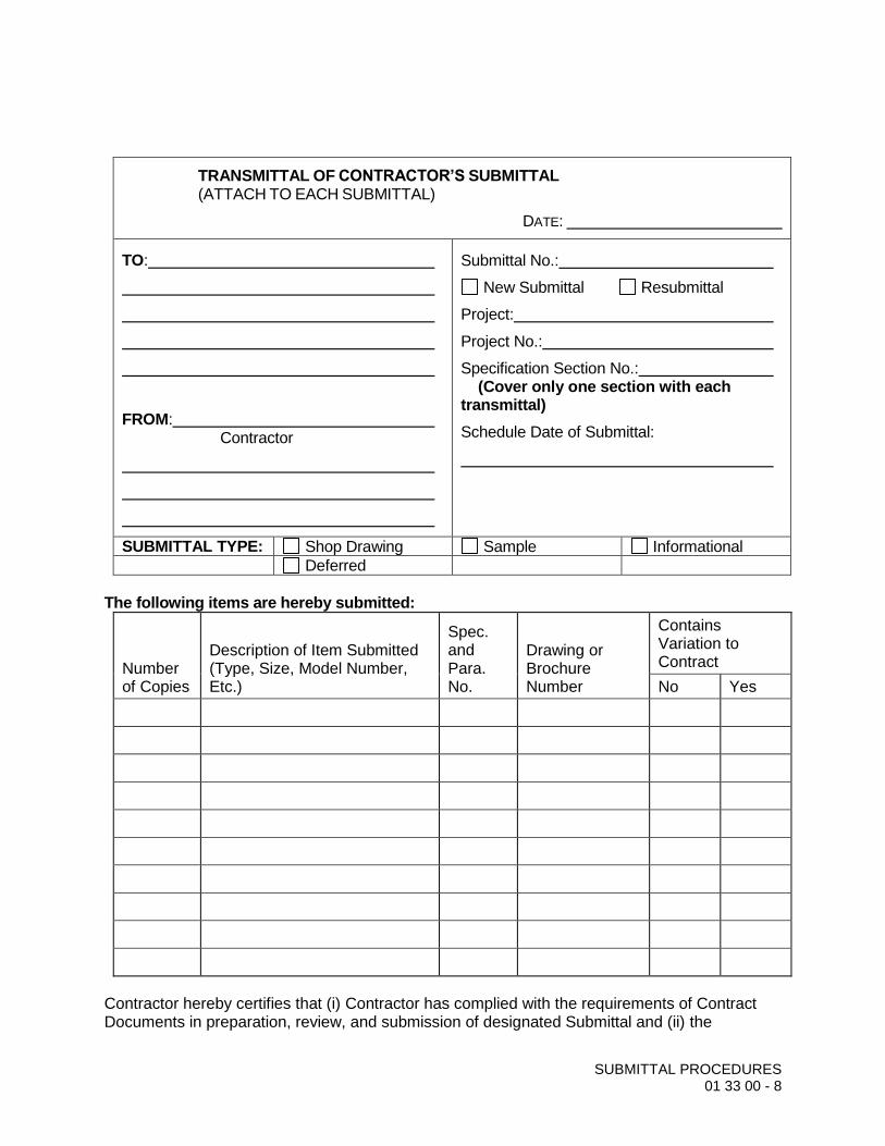
SUBMITTAL PROCEDURES 01 33 00 - 8
TRANSMITTAL OF CONTRACTOR’S SUBMITTAL (ATTACH TO EACH SUBMITTAL)
DATE:
TO:
FROM: Contractor
Submittal No.:
New Submittal Resubmittal
Project:
Project No.:
Specification Section No.: (Cover only one section with each transmittal)
Schedule Date of Submittal:
SUBMITTAL TYPE: Shop Drawing Sample Informational
Deferred
The following items are hereby submitted:
Number of Copies
Description of Item Submitted (Type, Size, Model Number, Etc.)
Spec. and Para. No.
Drawing or Brochure Number
Contains Variation to Contract
No Yes
Contractor hereby certifies that (i) Contractor has complied with the requirements of Contract Documents in preparation, review, and submission of designated Submittal and (ii) the

SUBMITTAL PROCEDURES 01 33 00 - 9
Submittal is complete and in accordance with the Contract Documents and requirements of laws and regulations and governing agencies.
By:___________________________________ Contractor (Authorized Signature)

CONTRACTOR QUALITY CONTROL 01 45 16.13 - 1
SECTION 01 45 16.13 CONTRACTOR QUALITY CONTROL
PART 1 GENERAL
REFERENCES
A. The following is a list of standards which may be referenced in this Section:
DEFINITIONS
A. Design-Builder Quality Control (CQC): The means by which the Design-Builder ensures that the construction, to include that performed by Subcontractors and Suppliers, complies with the requirements of the Contract.
B. Preliminary Work: The work carried out on the job site before the start of the main construction activities but not actually part of the construction work.
C. Definable Feature of Work (DFOW):
D. The DFOWs consist of individual tasks that together comprise each distinct component. The grouping of individual tasks associated with each DFOW is established to create the QC requirements for implementation of the three-phase inspection process. For the purposes of this contract, the DFOWs are the payment items as listed in the Proposal Form,
SUBMITTALS
A. Informational Submittals:
CQC Plan: Submit, not later than 14 days after receipt of Notice to Proceed.
CQC Report: Submit, weekly, an original and one copy in report form.
ENGINEER’S QUALITY ASSURANCE
A. All Work is subject to Engineer’s quality assurance inspection and testing at all locations and at all reasonable times before acceptance to ensure strict compliance with the terms of the Contract Documents.
B. Engineer’s quality assurance inspections and tests are for the sole benefit of City and do not:
Relieve the Design-Builder of responsibility for providing adequate quality control measures;
Relieve the Design-Builder of responsibility for damage to or loss of the material before acceptance;
Constitute or imply acceptance; or
Affect the continuing rights of City after acceptance of the completed Work.

CONTRACTOR QUALITY CONTROL 01 45 16.13 - 2
C. The presence or absence of a quality assurance inspector does not relieve the Design-Builder from any Contract requirement.
D. Promptly furnish all facilities, labor, and material reasonably needed for performing such safe and convenient inspections and tests as may be required by Engineer.
E. City may charge the Design-Builder for any additional cost of inspection or test when Work is not ready at the time specified by the Design-Builder for inspection or test, or when prior rejection makes re-inspection or retest necessary. Quality assurance inspections and tests will be performed in a manner that will not unnecessarily delay the Work.
PART 2 PART 2 PRODUCTS (NOT USED)
PART 3 PART 3 EXECUTION
GENERAL
A. Maintain an adequate inspection system and perform such inspections as will ensure that the Work conforms to the Contract Documents.
B. Maintain complete inspection records and make them available at all times to the City.
C. The quality control system shall consist of plans, procedures, and organization necessary to produce an end product that complies with the Contract Documents. The system shall cover all dredging related activities, including transportation and disposal of sediments and debris.
COORDINATION MEETING
A. After the Preconstruction Conference, but before start of construction and prior to acceptance of the CQC Plan, schedule a meeting with the City to discuss the quality control system.
B. Develop a mutual understanding of the system details, including the forms for recording the CQC operations, control activities, testing, administration of the system for both onsite and offsite Work, and the interrelationship of the Design-Builder’s management and control with the City’s quality assurance requirements.
C. There may be occasions when subsequent conferences may be called by either party to reconfirm mutual understandings and/or address deficiencies in the CQC system or procedures that may require corrective action by the Design-Builder.
QUALITY CONTROL ORGANIZATION
A. CQC System Manager:

CONTRACTOR QUALITY CONTROL 01 45 16.13 - 3
Designate an individual within the Design-Builder’s organization who shall be responsible for overall management of CQC and have the authority to act in CQC matters for the Design-Builder.
CQC System Manager may perform other duties on the Project.
CQC System Manager shall be an experienced construction person, with a minimum of 3 years construction experience on similar type Work.
CQC System Manager shall report to the Design-Builder’s project manager or someone higher in the organization. Project manager in this context shall mean the individual with responsibility for the overall quality and production management of the Project.
CQC System Manager shall be onsite during all phases of dredging activities.
Identify an alternate for CQC System Manager to serve with full authority during the System Manager’s absence. The requirements for the alternate shall be the same as for designated CQC System Manager.
B. CQC Staff:
Designate a CQC staff, available at the Site at all times during progress, with complete authority to take any action necessary to ensure compliance with the Contract. CQC staff members shall be subject to acceptance by Engineer.
CQC staff shall take direction from CQC System Manager in matters pertaining to QC.
CQC staff must be of sufficient size to ensure adequate QC coverage of Work phases, work shifts, and work crews involved in the construction. These personnel may perform other duties, but must be fully qualified by experience and technical training to perform their assigned QC responsibilities and must be allowed sufficient time to carry out these responsibilities.
The actual strength of the CQC staff may vary during any specific Work period to cover the needs of the Project. Add additional staff when necessary for a proper CQC organization.
C. Organizational Changes: Obtain City’s acceptance before replacing any member of the CQC staff. Requests for changes shall include name, qualifications, duties, and responsibilities of the proposed replacement.
QUALITY CONTROL PHASING
A. CQC shall include at least three phases of control to be conducted by CQC System Manager for all definable features of Work, as follows:
Preparatory Phase:

CONTRACTOR QUALITY CONTROL 01 45 16.13 - 4
a. Notify City at least 48 hours in advance of beginning any of the required action of the preparatory phase.
b. This phase shall include a meeting conducted by the CQC System Manager and attended by the superintendent, other CQC personnel (as applicable), and the foreman responsible for the definable feature. The CQC System Manager shall instruct applicable CQC staff as to the acceptable level of workmanship required in order to meet Contract requirements.
c. Document the results of the preparatory phase meeting by separate minutes prepared by the CQC System Manager and attached to the QC report.
d. Perform prior to beginning Work on each definable feature of Work:
Review applicable Contract Specifications.
Review applicable Contract drawings.
Verify that all materials and/or equipment have been tested, submitted, and approved.
Verify that provisions have been made to provide required control inspection and testing.
Examine the Work area to verify that all required preliminary Work has been completed and is in compliance with the Contract.
Perform a physical examination of required materials, equipment, and sample Work to verify that they are on hand, conform to approved Shop Drawing or submitted data, and are properly stored.
Review the appropriate activity hazard analysis to verify safety requirements are met.
Review procedures for constructing the Work, including repetitive deficiencies.
Document construction tolerances and workmanship standards for that phase of the Work.
Check to verify that the plan for the Work to be performed, if so required, has been accepted by Engineer.
Initial Phase:
a. Accomplish at the beginning of a definable feature of Work:
Notify City at least 48 hours in advance of beginning the initial phase.

CONTRACTOR QUALITY CONTROL 01 45 16.13 - 5
Perform prior to beginning Work on each definable feature of Work:
Review minutes of the preparatory meeting.
a) Check preliminary Work to verify compliance with Contract requirements.
b) Verify required control inspection and testing.
c) Establish level of workmanship and verify that it meets minimum acceptable workmanship standards. Comparison with sample panels is appropriate.
d) Resolve all differences.
e) Check safety to include compliance with and upgrading of the safety plan and activity hazard analysis. Review the activity analysis with each worker.
Separate minutes of this phase shall be prepared by the CQC System Manager and attached to the QC report. Exact location of initial phase shall be indicated for future reference and comparison with follow-up phases.
The initial phase should be repeated for each new crew to work onsite, or any time acceptable specified quality standards are not being met.
Follow-up Phase:
a. Perform daily checks to verify continuing compliance with Contract requirements, including control testing, until completion of the particular feature of Work.
b. Daily checks shall be made a matter of record in the CQC documentation and shall document specific results of inspections for all features of Work for the day or shift.
c. Conduct final follow-up checks and correct all deficiencies prior to the start of additional features of Work that will be affected by the deficient Work. Constructing upon or concealing nonconforming Work will not be allowed.
Additional Preparatory and Initial Phases: Additional preparatory and initial phases may be conducted on the same definable features of Work as determined by City if the quality of ongoing Work is unacceptable; or if there are changes in the applicable QC staff or in the onsite production supervision or work crew; or if work on a definable feature is resumed after a substantial period of inactivity, or if other problems develop.

CONTRACTOR QUALITY CONTROL 01 45 16.13 - 6
CONTRACTOR QUALITY CONTROL PLAN
A. General:
Plan shall identify personnel, procedures, control, instructions, test, records, and forms to be used.
Construction will be permitted to begin only after acceptance of the CQC Plan.
B. Content:
Plan shall cover the intended CQC organization for the entire Contract and shall include the following, as a minimum:
a. Organization: Description of the quality control organization, including a chart showing lines of authority and acknowledgment that the CQC staff shall implement the three-phase control system
b. CQC Staff: The name, qualifications (in resume format), duties, responsibilities, and authorities of each person assigned a QC function.
CONTRACTOR QUALITY CONTROL 01 45 16.13 - 7
c. Letters of Authority: A copy of a letter to the CQC System Manager signed by an authorized official of the firm, describing the responsibilities and delegating sufficient authorities to adequately perform the functions of the CQC System Manager, including authority to stop Work which is not in compliance with the Contract. The CQC System Manager shall issue letters of direction to all other various quality control representatives outlining duties, authorities and responsibilities. Copies of these letters shall also be furnished to the Owner.
d. Submittals: Procedures for scheduling, reviewing, certifying, and managing submittals, including those of subcontractors, suppliers, and purchasing agents.
e. Testing: Control, verification and acceptance testing procedures for each specific test to include the test name, frequency, specification paragraph containing the test requirements, the personnel and laboratory responsible for each type of test, and an estimate of the number of tests required.
f. Procedures for tracking preparatory, initial, and follow-up control phases and control, verification, and acceptance tests, including documentation.
g. Procedures for tracking deficiencies from identification through acceptable corrective action. These procedures will establish verification that identified deficiencies that have been corrected.
h. Reporting procedures, including proposed reporting formats; include a copy of the CQC report form.
C. Acceptance of Plans: Acceptance of the Design-Builder’s basic and addendum CQC plans is required prior to the start of construction. Acceptance is conditional and will be predicated on satisfactory performance during the construction. The Owner reserves the right to require the Design-Builder to make changes in the CQC plan and operations including removal of personnel, as necessary, to obtain the quality specified.
D. Notification of Changes: After acceptance of the CQC plan, the Design-Builder shall notify Engineer, in writing, a minimum of 7 calendar days prior to any proposed change. Proposed changes are subject to acceptance by City.
CONTRACTOR QUALITY CONTROL REPORT
A. As a minimum, prepare a CQC report for every 7 calendar days. Account for all days throughout the life of the Contract. Reports shall be signed and dated by CQC System Manager. Include copies of test reports and copies of reports prepared by QC staff.
B. Maintain current records of quality control operations, activities, and tests performed, including the Work of subcontractors and suppliers.

CONTRACTOR QUALITY CONTROL 01 45 16.13 - 8
C. Records shall be on an acceptable form and shall be a complete description of inspections, the results of inspections, daily activities, tests, surveys, and other items, including but not limited to the following:
Design-Builder/subcontractor and their areas of responsibility.
Operating/equipment with hours worked, idle, or down for repair.
Work performed today, giving location, description, and by whom. When a network schedule is used, identify each phase of Work performed each day by activity number.
Test and/or control activities performed with results and references to specifications/plan requirements. The control phase should be identified (Preparatory, Initial and Follow-up). List deficiencies noted along with corrective action.
Material received with statement as to its acceptability and storage.
Identify submittals reviewed, with Contract reference, by whom, and action taken.
Offsite surveillance activities, including actions taken.
All transportation and disposal documents
Job safety evaluations stating what was checked, results, and instructions or corrective actions.
List instructions given/received and conflicts in the drawings and/or Specifications.
The Design-Builder’s verification statement.
Indicate a description of trades working on the Project; the number of personnel working; weather conditions encountered; and any delays encountered.
These records shall cover both conforming and deficient features and shall include a statement that equipment and materials incorporated in file work and workmanship comply with the Contract.
CONTRACTOR QUALITY CONTROL 01 45 16.13 - 9
SUBMITTAL QUALITY CONTROL
A. Submittals shall be as specified in Section 01 33 00, Submittal Procedures. The CQC organization shall be responsible for certifying that all submittals are in compliance with the Contract requirements. Engineer will furnish copies of test report forms upon request by the Design-Builder. The Design-Builder may use other forms as approved.
TESTING/SURVEY QUALITY CONTROL
A. Testing Procedure:
Perform tests/survey specified or required to verify that control measures are adequate to provide a product which conforms to Contract requirements. Perform the following activities and record the following data:
a. Verify testing/surveying procedures comply with contract requirements.
b. Verify facilities and testing/survey equipment are available and comply with testing standards.
c. Check test/survey instrument calibration data against certified standards.
d. Verify recording forms and test/survey identification control number system, including all of the test/survey documentation requirements, have been prepared.
e. Documentation:
Record results of all tests taken, both passing and failing, on the CQC report for the date taken.
Include specification paragraph reference, location where tests were taken, and the sequential control number identifying the test.
Actual test reports may be submitted later, if approved by Engineer, with a reference to the test number and date taken.
Provide directly to Engineer an information copy of tests performed by an offsite or commercial test facility. Test results shall be signed by an engineer registered in the state where the tests are performed.
Failure to submit timely test reports, as stated, may result in nonpayment for related Work performed and disapproval of the test facility for this Contract.
B. Testing Laboratories:
Analytical laboratory facilities shall be Environmental Laboratory Accreditation Program (ELAP) certified.

CONTRACTOR QUALITY CONTROL 01 45 16.13 - 10
COMPLETION INSPECTION
A. CQC System Manager shall conduct an inspection of the Work at the completion of all Operational Sections or any milestone established by a completion time stated in the Contract.
B. Completion inspections need to be performed before equipment or subcontractors required for any element of the Work are demobilized from each OS.
C. Punchlist:
CQC System Manager shall develop a punchlist of items which do not conform to the Contract requirements.
Include punchlist in the CQC report, indicating the estimated date by which the deficiencies will be corrected.
CQC System Manager or staff shall make a second inspection to ascertain that all deficiencies have been corrected and so notify the City.
These inspections and any deficiency corrections required will be accomplished within the time stated for completion of the entire Work or any particular increment thereof if the Project is divided into increments by separate completion dates.
END OF SECTION

TEMPORARY FACILITIES AND CONTROLS 01 50 00 - 1
SECTION 01 50 00 TEMPORARY FACILITIES AND CONTROLS
PART 1 GENERAL
REFERENCES
A. The following is a list of standards which may be referenced in this section:
American Nursery and Landscape Association (ANLA): American Standards for Nursery Stock.
National Fire Prevention Association (NFPA): 241, Standard for Safeguarding Construction, Alteration, and Demolition Operations.
U.S. Department of Agriculture (USDA): Urban Hydrology for Small Watersheds.
U.S. Weather Bureau: Rainfall-Frequency Atlas of the U.S. for Durations from 30 Minutes to 24 Hours and Return Periods from 1 to 100 Years.
SUBMITTALS
A. Informational Submittals:
Copies of the Design-Builder-obtained permits and approvals for construction as required by Laws and Regulations and governing agencies.
Temporary Construction Submittals:
a. Parking area plans.
pp. The Design-Builder field offices, storage yard, and storage building plans.
qq. Fencing and protective barrier locations and details.
rr. Sediment Processing Area location plan. At each access location
ss. Marine traffic schedules and routing plans.
tt. Traffic and Routing Plans (MOT’s): As specified below.
uu. Temporary Control Submittals:
vv. Noise control plan.
ww. Dust control plan.
xx. Plan for disposal of waste materials (sediments and debris) and intended haul routes.

TEMPORARY FACILITIES AND CONTROLS 01 50 00 - 2
MOBILIZATION
A. Mobilization shall include, but not be limited to, these principal items:
Obtaining required permits.
Installing temporary construction power, wiring, and lighting facilities. If required and included in access agreements
Providing onsite communication facilities, including telephones.
Providing onsite sanitary facilities and potable water facilities as specified and as required by Laws and Regulations, and governing agencies.
Posting OSHA required notices and establishing safety programs and procedures.
Having the Design-Builder’s staff at the Site full time.
PROTECTION OF WORK AND PROPERTY
A. Keep City informed of serious onsite accidents and related claims.
B. Use of Explosives: No blasting or use of explosives will be allowed onsite.
C. Dock facilities - none provided by the City.
VEHICULAR TRAFFIC
A. Traffic Routing Plan: Show sequence of construction affecting use of roadways, time required for each phase of the Work, phasing of operations to provide necessary access, and plans for signing, barricading, and striping to provide passages for pedestrians and vehicles.
B. Traffic Control Plan: Adhere to traffic control plan reviewed and accepted by the City or its designee. Changes to this plan shall be made only by written approval of the City or its designee. Secure approvals for necessary changes so as not to delay progress of the Work.
PROJECT SIGN
A. Provide and maintain one, 8-ft-wide by 4-ft-high sign constructed of 3/4-inch exterior high density overlaid plywood. Sign shall bear name of the Design-Builder and Project Address. Lettering shall be blue applied on white background by an experienced sign painter. Paint shall be exterior type enamel. Information to be included will be provided by Engineer. An example project sign is presented below:

TEMPORARY FACILITIES AND CONTROLS 01 50 00 - 3
PART 2 PART 2 PRODUCTS (NOT USED)
PART 3 EXECUTION
3.01 CONTRACTOR’S FIELD OFFICE (if provided by Design-Builder)
A. Located [SPECIFY]; verify and adjust level, block, tie down, skirt, provide stairways, and relocate when necessary and approved. Construct on proper foundations, and provide proper surface drainage and connections for utility services.
B. Raise grade under field office, as necessary, to elevation adequate to avoid flooding.
C. Provide sanitary facilities in compliance with state and local health authorities.
D. Provide janitorial service on a weekly basis.
E. Exterior Door Keys: Furnish two sets of keys.

TEMPORARY FACILITIES AND CONTROLS 01 50 00 - 4
F. Telephone:
Provide number of incoming lines equal to that specified for telephone type.
Provide separate analog fax line.
Provide appropriate jacks; locate as directed by Engineer.
Provide wiring necessary for complete telephone system.
G. Telecommunications:
Provide broad band internet connection with minimum of five live portable computer (PC) ports.
Provide appropriate jacks, CAT-5 patch cords, wiring, and equipment required for a complete telecommunications system.
Arrange and provide for telecommunication service for use during construction. Pay costs of installation, maintenance, and monthly service of internet connection.
H. Maintain in good repair and appearance, and provide weekly cleaning service and replenishment, as required, of paper towels, paper cups, hand soap, toilet paper, first-aid kit supplies, and bottled water.
I. Replenish, as needed, facsimile paper, duplicator paper and toner, computer paper, and printer toner.
J. Set up and provide monthly electric, telephone and internet service to trailer for the duration of the contract period. Telephone service shall include local and long distance.
3.02 TEMPORARY UTILITIES
A. Power: If required, cost of electric power shall be borne by the Design-Builder.
B. Water:
No construction or potable water is available at Site. Make arrangements for and bear costs of providing water required for construction purposes and for drinking by personnel during construction.
Hydrant Water:
a. No construction or potable water is available at Site. Make arrangements for and bear costs of providing water required for construction purposes and for drinking by construction personnel during construction.

TEMPORARY FACILITIES AND CONTROLS 01 50 00 - 5
b. If any hydrants are available nearby for use - secure written permission for connection and use from water department and meet requirements for use. Notify fire department before obtaining water from fire hydrants.
c. Use only special hydrant-operating wrenches to open hydrants. Make certain hydrant valve is open full, since cracking valve causes damage to hydrant. Repair damaged hydrants and notify appropriate agency as quickly as possible. Hydrants shall be completely accessible to fire department at all times.
d. Include costs to connect and transport water to construction areas in Contract Price.
C. Sanitary and Personnel Facilities:
Provide and maintain facilities for the Design-Builder’s employees, Subcontractors, and other onsite employers’ employees. Service, clean, and maintain facilities and enclosures.
Provide in accordance with State and Local Health Authorities: Sanitary facilities to include a portable hand-wash station.
D. Electric, Telephone and High Speed Internet Service: The Design-Builder shall arrange and provide onsite telephone and high speed internet service as needed during construction. The Design-Builder to pay costs of monthly bills until Contract closeout.
E. Fire Protection: Furnish and maintain on Site adequate firefighting equipment capable of extinguishing incipient fires. Comply with applicable parts of NFPA 241.
3.03 PROTECTION OF WORK AND PROPERTY
A. General:
Perform Work within right-of-way and easements in a systematic manner that minimizes inconvenience to property owners and the public.
Maintain in continuous service existing pipelines, underground power, telephone or communication cable, water mains, irrigation lines, sewers, poles and overhead power, and other utilities encountered in Work area, unless other arrangements satisfactory to owners of said utilities have been made.
Where completion of the Work requires temporary or permanent removal or relocation of existing utility, coordinate activities with owner of said utility and perform work to their satisfaction.
Protect and maintain underground pipes, conduits, drains, and other underground utility construction uncovered or otherwise affected by construction operations.

TEMPORARY FACILITIES AND CONTROLS 01 50 00 - 6
Keep fire hydrants and water control valves free from obstruction and available for use at all times.
In areas where the Design-Builder’s operations are adjacent to or near a utility, such as gas, telephone, television, electric power, water, sewer, or irrigation system, and such operations may cause damage or inconvenience, suspend operations until arrangements necessary for protection have been made by the Design-Builder.
Notify property owners and utility offices that may be affected by construction operation at least 2 days in advance: Before exposing a utility, obtain utility owner’s permission. Should service of utility be interrupted due to the Design-Builder’s operation, notify proper authority immediately. Cooperate with said authority in restoring service as promptly as possible and bear costs incurred.
Do not impair operation of existing sewer system. Prevent construction material, pavement, concrete, earth, volatile and corrosive wastes, and other debris from entering sewers, pump stations, or other sewer structures.
Maintain original Site drainage wherever possible.
B. Site Security:
Erect a temporary security enclosure as needed at the active project work areas.
Site security personnel shall patrol active project work areas.
C. Barricades and Lights:
Provide as necessary to prevent unauthorized entry to construction areas and affected roads, streets, and alleyways, inside and outside of fenced area, and as required to ensure public safety and the safety of the Design-Builder’s employees, other employer’s employees, and others who may be affected by the Work.
Provide to protect existing facilities and adjacent properties from potential damage.
Protect streets, roads, highways, and other public thoroughfares that are closed to traffic by effective barricades with acceptable warning signs.
Locate barricades at the nearest intersecting public thoroughfare on each side of blocked section. In accordance with approved MOT’s.
Illuminate barricades and obstructions with warning lights from sunset to sunrise.in accordance with approved MOT’s.
D. Signs and Equipment:
TEMPORARY FACILITIES AND CONTROLS 01 50 00 - 7
Conform to requirements of manual published by the Department of Transportation.
Traffic Cones: Provide to delineate traffic lanes to guide and separate traffic movements.
High-Level Warning Flag Units in accordance with approved MOT’s. Provide in advance of traffic approaching the Work, each displaying three flags mounted at a height of 9 feet.
Navigational aid and warning buoys should be deployed at appropriate locations.
Lights shall be provided for installed equipment being used to perform Work even when not in use.
E. Existing Structures:
Where the Design-Builder contemplates removal of small structures such as mailboxes, signposts, and culverts that interfere with the Design-Builder’s operations, obtain approval of property owner and City. Property owner’s approval shall be documented in the executed access agreement.
Replace items removed in their original location and a condition equal to or better than original.
F. Archaeological Finds:
General: Should finds of an archaeological or paleontological nature be made within Site limits, immediately notify the Owner and Engineer and proceed in accordance with General Conditions. Continue the Work in other areas without interruption.
Archaeological Finds: Evidence of human occupation or use of an area within contract limits.
Paleontological Finds: Evidence of prehistoric plant or animal life, such as skeletons, bones, fossils, or casts and other indications such as pictographs.
The Owner or Engineer may order the Work stopped in other areas if, in the Owner’s or Engineer’s opinion, find is more extensive than may appear from uncovered material.
Protection of Finds:
a. Cover, fence, or otherwise protect finds until notice to resume the Work is given.
b. Cover finds with plastic film held in place by earth, rocks, or other weights placed outside the find. Should additional backfilling be

TEMPORARY FACILITIES AND CONTROLS 01 50 00 - 8
necessary for safety or to prevent caving, place backfill material loosely over plastic film.
c. Sheet or shore as necessary to protect excavations underway. Place temporary fence to prevent unauthorized access.
d. Dewater finds made below water table as necessary to protect construction Work underway. Divert groundwater or surface runoff away from find by ditching or other acceptable means.
Removal of Finds:
a. Finds are property of the Owner. Do not remove or disturb finds without the Owner’s written authorization.
b. Should the Owner elect to have a find removed, provide equipment, labor, and material to permit safe removal of find without damage. Provide transportation for delivery to individuals, institutions, or other places as the Owner may find desirable, expedient, or required by law.

TEMPORARY FACILITIES AND CONTROLS 01 50 00 - 9
3.04 TEMPORARY CONTROLS
A. Air Pollution Control (Refer to Site Plans):
Minimize air pollution from construction operations as presented in the Air Monitoring Plan (AMP).
Burning of waste materials, rubbish, or other debris shall not be permitted.
Conduct operations of dredging and loading sediment and debris dumping rock and of carrying rock away in trucks to cause a minimum of dust. Give unpaved streets, roads, detours, or haul roads used in construction area a dust-preventive treatment or periodically water to prevent dust. Strictly adhere to applicable environmental regulations for dust prevention.
Provide and maintain temporary dust-tight partitions, bulkheads, or other protective devices during construction. Construct partitions of plywood, insulating board, plastic sheets, or similar material.
Minimize dust from any site operations.
Comply with local dust control ordinances.
Implement mitigation methods and equipment outlined in Dust Control Plan.
B. Noise Control:
Comply with applicable portions of the City of Miami Code, including by not limited to:
Chapter 66, Article III – Noise: Minimize noise from construction operations.
Comply with local noise control ordinances.
Implement mitigation methods and equipment outlined in Noise Control Plan.
C. Water Pollution Control:
Prior to commencing dredging activities, obtain City’s agreement with detailed plans showing procedures intended to handle and dispose of water and stormwater.
Comply with 01 57 13, Temporary Erosion and Sedimentation Control, for stormwater flow and surface runoff.
Do not dispose of any materials in storm or sanitary drains. Disposal of materials into streams or waterways is prohibited. Provide acceptable containers for collection and disposal of waste materials, debris, and rubbish.
Water pollution control methods shall be in compliance with applicable permits.
TEMPORARY FACILITIES AND CONTROLS 01 50 00 - 10
Discharge of surface water that was in contact with contaminated soil, sediment or debris into the Wagner Creek/Seybold Canal waterways will not be allowed without approval by the City.
D. Erosion, Sediment, and Flood Control: Provide, maintain, and operate temporary facilities as specified in Section 01 57 13, Temporary Erosion and Sedimentation Control, to control erosion and sediment releases, and to protect the Work and existing facilities from flooding during construction period.
3.05 STORAGE YARDS AND BUILDINGS
A. Off-Site Temporary Storage Yards: Identify the location.
B. Off-Site Temporary Storage Buildings: Identify the location.
C. On-Site Temporary Storage Yards: Construct temporary storage yards for storage of products that are not subject to damage by weather conditions.
D. On-Site Temporary Storage Buildings:
Provide environmental control systems that meet recommendations of manufacturers of equipment and materials stored.
Arrange or partition to provide security of contents and ready access for inspection and inventory.
Store combustible materials (paints, solvents, fuels) in a well-ventilated and remote building meeting safety standards.
3.06 ACCESS ROADS
A. Construct access roads within easements, rights-of-way, as detailed in the executed access agreements. Utilize existing roads where shown.
B. Maintain drainage ways – Install and maintain materials to ensure existing drainage patterns function properly. Install and maintain culverts to allow water to flow beneath access roads. Provide corrosion-resistant culvert pipe of adequate strength to resist construction loads
C. Provide gravel, crushed rock, or other stabilization material to permit access by all motor vehicles/equipment at all times.
D. Maintain road grade and crown to eliminate potholes, rutting, and other irregularities that restrict access.
E. Coordinate with the City and detours and other operations affecting traffic and access. All changes to traffic patterns must be approve d prior to the work and be noted on the approved MOT plans.
F. Upon completion of construction, restore ground surface disturbed by site access activities original line and grade.

TEMPORARY FACILITIES AND CONTROLS 01 50 00 - 11
3.07 PARKING AREAS
A. Control vehicular parking to preclude interference with public traffic or parking, access by emergency vehicles, or construction operations.
B. Provide parking facilities for personnel working on the Project.to be included in any access agreements
3.08 MARINE TRAFFIC
A. In accordance with General Terms and Conditions and Marine Requirements, as discussed in Section 35 20 25.23, Mechanical Environmental Dredging.
3.09 VEHICULAR TRAFFIC
A. Comply with Laws and Regulations regarding closing or restricting use of public streets or highways. No public or private road shall be closed, except by written permission of proper authority. Ensure the least possible obstruction to traffic and normal commercial pursuits.
B. Conduct the Work to interfere as little as possible with public travel, whether vehicular or pedestrian.
C. Whenever it is necessary to cross, close, or obstruct roads, driveways, and walks, whether public or private, secure proper approval and document in approved MOT plans and access agreements.
D. Maintenance of traffic is not required if the Design-Builder obtains written permission from the Owner and tenant of private property, or from authority having jurisdiction over public property involved, to obstruct traffic at designated point.
E. When flaggers and guards are required by regulation or when deemed necessary for safety, furnish them with approved orange wearing apparel and other regulation traffic control devices.
F. Notify fire department and police department before closing any street or portion thereof. Notify said departments when streets are again passable for emergency vehicles. Do not block off emergency vehicle access to consecutive arterial crossings or dead-end streets, without written permission from fire department. Conduct operations with the least interference to fire equipment access, and at no time prevent such access. Furnish the Design-Builder’s night emergency telephone numbers to police department.
3.10 CLEANING DURING CONSTRUCTION
A. In accordance with General Conditions, as may be specified in other Specification sections, and as required herein.
B. Wet down exterior surfaces prior to sweeping to prevent blowing of dust and debris. Pick up and dispose of debris daily –at the completion of site activities.

TEMPORARY FACILITIES AND CONTROLS 01 50 00 - 12
C. Provide approved containers for collection and disposal of waste materials, debris, and rubbish. Dispose of such waste materials, debris, and rubbish offsite.
D. Daily brush, sweep entry drive, roadways, and other streets and walkways affected by the Work and where adjacent to the Work.
3.11 FUEL HANDLING
A. At no time shall overtopping fuel tank or spillage to ground surface be allowed.
3.12 PROTECTION OF THE ENVIRONMENT
A. Minimize air pollution by use of properly operating combustion emission control devices on construction vehicles and equipment. Encourage shutdown of motorized equipment not in use.
B. All waste materials other than contaminated sediment and debris encountered during sediment removal shall be hauled to a licensed solid waste landfill, or otherwise disposed of in an environmentally sound manner and in compliance with all applicable local, state and federal rules.
C. Hazardous waste, if any, shall be stored, handled, and disposed of in compliance with all applicable local, state and federal rules.
D. Other measures shall be taken, as necessary, to maintain work site in an environmentally sound matter.
E. All spills or leaks of fuels, oil, or other reportable liquids resulting from handling or equipment malfunctions shall be reported immediately to the City, who shall report the spill. Affected soils shall be properly removed from limits of construction. Fuel spills in public waterways, or releases of NAPL during sediment excavation, shall be properly contained with containment booms and removed with appropriate absorbent materials, as necessary to minimize offsite discharge. All affected soils and other affected materials/debris shall be disposed in accordance with applicable local, state and federal rules as well, as the sole expense of the Design-Builder and as agreed by the City. A copy of the manifests, if necessary, shall be provided to City within five working days of disposal. City reserves right to order leaking equipment removed from site.
END OF SECTION

TEMPORARY EROSION AND SEDIMENT CONTROL 01 57 13 - 1
SECTION 01 57 13 TEMPORARY EROSION AND SEDIMENT CONTROL
PART 1 GENERAL
WORK OF THIS SECTION
A. This section covers work necessary for stabilization of soil to prevent erosion during and after construction, dredging and land disturbing activities. The work shall include the furnishing of all labor, materials, tools, and equipment to perform the work and services necessary as herein specified and as indicated on the drawings. This shall include installation, maintenance, and final removal of all temporary soil erosion and sediment control measures.
B. The minimum areas requiring soil erosion and sediment control measures are to be indicated on the plans for each access location. The right is reserved to modify the use, location, and quantities of soil erosion and sediment control measures based on activities of the Design-Builder and as the City considers to be in the best interest of the property owner and the City, and in compliance with Miami-Dade and City regulations.
C. The work consists of implementing the stormwater pollution prevention measures to prevent sediment from entering streams or water bodies as specified in this Section, and the requirements of the National Pollution Discharge Elimination System (NPDES).
GENERAL
A. See Conditions of the Contract and Division 1, General Requirements, which contain information and requirements that apply to the Work specified herein and are mandatory for this project.
B. All activities shall conform to the Standards and Specifications for Erosion and Sediment Control, the specifications, and the Drawings. In the event of a conflict, the more stringent requirement shall apply.
C. Soil erosion stabilization and sedimentation control consist of the following elements:
Construction of temporary erosion control facilities such as silt fences, check dams, etc.
Placement and maintenance of temporary seeding/sodding on all areas disturbed by construction.
D. The Design-Builder shall be responsible for phasing Work in areas allocated for his exclusive use during this Project. This will include installation of any temporary erosion control devices, ditches, or other facilities.

TEMPORARY EROSION AND SEDIMENT CONTROL 01 57 13 - 2
E. The areas set aside, in accordance with the Design-Builder’s executed access agreements, use may be temporarily developed to provide satisfactory working, staging areas, for his use. Preparation of these areas shall be in accordance with other requirements contained within these Specifications and shall be done in a manner to control and restrict sediment transport away from the area.
F. The Design-Builder shall maintain and clean construction entrance at all points of construction ingress and egress, in accordance to approved plans
G. Sediment transport and erosion from work areas shall be controlled and restricted from moving beyond the immediate work area by construction of temporary toe-of-slope ditches and accompanying silt fences, as necessary. The Design-Builder shall keep these temporary facilities in operational condition by regular cleaning, regrading and maintenance.
H. The Design-Builder shall maintain all elements of the Soil Erosion Stabilization and Sedimentation Control systems and facilities to be constructed during this Project for the duration of his activities at each access location. Formal inspections made jointly by the Design-Builder and the City shall be conducted daily to evaluate the Design-Builder’s conformance to the requirements of both these Specifications and all required permits.
I. All sediment traps, if used, shall be cleaned of collected sediment after every rainfall or as determined from the daily inspections. Cleaning shall be done in a manner that will not direct the sediment into any storm drain piping system or into the waterway. Removed sediment shall be disposed of, off-site site, in accordance with the Design-Builder’s Transportation and Disposal Plan.
J. Replacement or repair of failed or overloaded silt fences, check dams, or other temporary erosion control devices shall be accomplished by the Design-Builder within 24 hours after receiving written notice from the City.
K. If the Design-Builder has not complied with any of the above maintenance efforts to the satisfaction of the City within 2 working days after receiving written notification, the City shall have the prerogative of engaging others to perform any needed maintenance or cleanup, including removal of accumulated sediment at constructed erosion control facilities, and deduct from the Design-Builder’s monthly partial payment the costs for such efforts plus a $1,500 administration fee.
L. Stabilization Practices:
The stabilization practices to be implemented include geotextiles, erosion control mats, protection of trees, preservation of mature vegetation, etc. in accordance with the current Standards and Specifications for Erosion and Sediment Control. On the Daily Report, record the dates when the major grading activities occur, (e.g., clearing and grubbing, and grading); when construction activities temporarily or permanently cease on a portion of the site; and when stabilization practices are initiated. Except as provided in below in subparagraph Unsuitable Conditions, and subparagraph No Activity for Less Than 21 Days, initiate stabilization practices as soon as practicable,

TEMPORARY EROSION AND SEDIMENT CONTROL 01 57 13 - 3
but no more than 14 days, in any portion of the site where construction activities have temporarily or permanently ceased.
Unsuitable Conditions: Where the initiation of stabilization measures by the 14th day after construction activity temporarily or permanently ceases or is precluded by unsuitable conditions caused by the weather, initiate stabilization practices as soon as practicable after conditions become suitable.
No Activity for Less Than 21 Days: When the total time period in which construction activity is temporarily ceased on a portion of the site is 21 days minimum, stabilization practices do not have to be initiated on that portion of the site until 14 days have elapsed after construction activity temporarily ceased.
Burn-off of the ground cover is not permitted.
Protection of Erodible Soils: Immediately finish the earthwork to a final grade, as indicated or specified, and protect the side slopes and back slopes upon completion of rough grading. Plan and conduct earthwork to minimize the duration of exposure of unprotected soils.
M. Erosion, Sediment and Stormwater Control:
Submit Stormwater Inspection Reports for General Permit to the City within 1 business day of performing inspections in accordance with Section IV.C of the SPDES General Permit for Stormwater Discharges from Construction Activity.
Note: Inspection Criteria varies with the area of disturbance and status of work,
The Design-Builder shall prepare a Stormwater Pollution Prevention Plan (SWPPP) for the Project. The SWPPP shall meet the requirements of the SPDES General Permit for Stormwater Discharges from Construction Activity, Permit No. GP-O-IO-00 I. The Design-Builder shall submit the SWPPP along with any required Notice of Intents, Notice of Termination, and appropriate permit fees, to the appropriate State agency for approval, a minimum of 14 calendar days prior to the start of any land disturbing activities.
Maintain an approved copy of the SWPPP at the onsite construction onsite locations, and continually update as regulations require, reflecting current site conditions. Include within the SWPPP:
Identify potential sources of pollution which may be reasonably expected to affect the quality of stormwater discharge from the site.
Describe and ensure implementation of practices which shall be used to reduce the pollutants in stormwater discharge from the site.
Ensure compliance with terms of the State of Florida general permit for stormwater discharge.

TEMPORARY EROSION AND SEDIMENT CONTROL 01 57 13 - 4
Install, inspect, and maintain best management practices (BMPs) as required by the general permit. Prepare and submit to the City, BMP Inspection Reports as required by the general permit.
Once construction is complete and the site has been stabilized with a final, sustainable cover, submit the Notice of Termination to the appropriate state Agency within 30 days after all land disturbing activities end.
N. Stormwater Drainage: Discharge of hazardous substances or stormwater that has been in contact with dredged materials shall not be permitted under any circumstances. Construction site runoff shall be prevented from entering any storm drain or waterway directly by the use of straw bales, retention berms or other method approved by the City. Provide erosion protection of the surrounding soils.
O. Structural Practices: Implement structural practices to divert flows from exposed soils, or otherwise limit runoff and the discharge of pollutants from exposed areas of the site. Implement structural practices in a timely manner, during the construction process, to minimize erosion and sediment runoff. Include the following devices:
Silt Fences: Provide silt fences as a temporary structural practice to minimize erosion and sediment runoff. Properly install silt fences to effectively retain sediment immediately after completing each phase of work where erosion would occur in the form of sheet and rill erosion (e.g. clearing and grubbing, excavation, embankment, and grading).
Straw Bales: Provide bales of straw as a temporary structural practice to minimize erosion and sediment runoff. If bales are used, properly place the bales to effectively retain sediment immediately after completing each phase of work. Show on the Drawings areas where straw bales are to be used.
TEMPORARY EROSION AND SEDIMENT CONTROL 01 57 13 - 5
Maintain Construction Entrance: Install a construction entrance to each access locations to reduce or eliminate the tracking of sediment onto public rights-of-way or streets. A stabilized construction entrance shall be used at all points of construction ingress and egress.
Any materials tracked onto roads shall be immediately contained and cleaned up by the Design-Builder to the satisfaction of the City.
Sediment Trap: Construct sediment traps as necessary to intercept sediment laden runoff and retain the sediment. Sediment shall be removed and the trap restored to the original dimensions when the sediment has accumulated to half of the design depth of the trap.
P. Vegetation and Mulch: Provide temporary protection on sides and back slopes as soon as rough grading is completed or sufficient soil is exposed to require erosion protection. Protect slopes by accelerated growth of permanent vegetation, temporary vegetation, mulching, or netting. Stabilize slopes by hydroseeding, anchoring mulch in place, covering with anchored netting, sodding, or such combination of these and other methods necessary for effective erosion control.
REFERENCES
A. The following is a list of standards which may be referenced in this section:
American Society for Testing Materials (ASTM) D4873, 2002(2009), Standard Guide for Identification, Storage, and Handling of Geosynthetic Rolls and Samples.
SUBMITTALS
A. Submittals shall be made in accordance with Section 01 33 00, Submittal Procedures.
B. Informational Submittals:
Stormwater Inspection Reports for General Permit.
Stormwater Notice of Termination.
Product information for erosion and sediment controls.
C. In addition, the Design-Builder shall provide the following specific information: Certificates of inspection of seed by state or federal authorities and copies of delivery invoices or other proof of quantities of fertilizer.
PART 2 PART 2 PRODUCTS
2.01 TEMPORARY SEED/SOD
A. Seed mixture shall match existing grass type.

TEMPORARY EROSION AND SEDIMENT CONTROL 01 57 13 - 6
B. Sod shall match existing grass type.
2.02 STRAW MULCH
A. Threshed straw of oats, wheat, barley, or rye, air dried and free from seed of noxious weeds.
B. Mulch shall be in accordance with Standard and Specification for Temporary Critical Area Plantings
2.03 WATER
A. Water shall contain no toxic elements that could be harmful to plant growth.
PART 3 PART 3 EXECUTION
3.01 GENERAL
A. The Design-Builder shall install erosion and sediment control measures and maintain in accordance with approved plans. The sequence of construction shown on the plans is made a part of these Contract Documents.
B. The Design-Builder shall provide and maintain temporary seeding at all times.
3.02 OS CONSTRUCTION/DREDGING ENTRANCES
A. The entrance shall be maintained in a condition which will prevent tracking of sediment and/or dirt onto public rights-of-way or streets. This may require periodic top dressing with additional aggregate.
3.03 SILT FENCES
A. Silt fences shall be in accordance with Section 4.4.1 (page 45) of the Florida Stormwater Erosion and Sedimentation Control Inspector’s Manual (Florida Department of Environmental Protection, Nonpoint Source Management Section, July 2008).
B. Mill Certificate or Affidavit: Provide a mill certificate or affidavit attesting that the fabric and factory seams meet chemical, physical, and manufacturing requirements specified above. Specify in the mill certificate or affidavit the actual Minimum Average Roll Values and identify the fabric supplied by roll identification numbers. Submit a mill certificate or affidavit signed by a legally authorized official from the company manufacturing the filter fabric.
3.04 STRAW BALES
A. Straw bales shall be installed, inspected and maintained in accordance with Standard and Specifications for Straw Bale Dike.
3.05 SEEDING AND SODDING
A. General:

TEMPORARY EROSION AND SEDIMENT CONTROL 01 57 13 - 7
The Design-Builder shall give at least 3 days' notice to the City prior to seeding or sodding to allow the City to inspect the prepared areas. The Design-Builder shall rework any areas not approved for seeding to the City’s satisfaction.
The Design-Builder shall keep the City advised of schedule of operations.
Seed shall match the existing grass type, be in accordance with any access agreements be clean, delivered in original unopened packages and bearing an analysis of the contents, guaranteed 95 percent pure with minimum germination rate of 85 percent. Sod shall match existing grass type and be in accordance with any access agreements.
B. Soil Stabilization and Temporary Seeding:
Soil stabilization seeding shall consist of the application of the following materials in quantities as further described herein for disturbed areas left inactive for more than 14 days.
a. Seed.
b. Mulch.
c. Maintenance.
C. Hydroseeding, if consistent with any access agreements, will be permitted as a method of applying seed and associated soil conditioning agents described above. Should the Design-Builder elect to apply soil stabilization seeding by hydroseeding methods, he shall submit his operational plan and methods to the City. Temporary Seeding is to be placed and maintained over all disturbed areas prior to Permanent Seeding. Maintain Temporary Seeding until such time as areas are approved for Permanent Seeding.
3.06 FIELD QUALITY CONTROL
A. Maintain the temporary and permanent vegetation, erosion and sediment control measures, and other protective measures in good and effective operating condition by performing routine inspections to determine condition and effectiveness, by restoration of destroyed vegetative cover, and by repair of erosion and sediment control measures and other protective measures. Use the following procedures to maintain the protective measures.
B. Silt Fence Maintenance: Inspect the silt fences in accordance with the SWPPP and SPDES requirements. Any required repairs shall be made promptly (within 24 hours). Pay close attention to the repair of damaged silt fence resulting from end runs and undercutting. Should the fabric on a silt fence decompose or become ineffective, and the barrier is still necessary, replace the fabric promptly. Remove sediment deposits when deposits reach one-third of the height of the barrier. Remove a silt fence when it is no longer required. The immediate area occupied by the fence and any sediment deposits shall be shaped to an

TEMPORARY EROSION AND SEDIMENT CONTROL 01 57 13 - 8
acceptable grade. The areas disturbed by this shaping shall receive erosion control.
C. Straw Bale Maintenance: Inspect straw bale barriers in accordance with the SWPPP and SPDES requirements. Pay close attention to the repair of damaged bales, end runs and undercutting beneath bales. Accomplish necessary repairs to barriers or replacement of bales in a prompt (within 24 hours) manner. Remove sediment deposits when deposits reach one-half of the height of the barrier. At the each end of each row turn bales uphill when used to retain sediment. Remove a straw bale barrier when it is no longer required. The immediate area occupied by the bales and any sediment deposits shall be shaped to an acceptable grade.
3.07 INSPECTIONS
A. General: Inspect disturbed areas of the construction site, areas that have not been finally stabilized used during dredging activities, areas exposed to precipitation, stabilization practices, structural practices, other controls, and area where vehicles exit the site at least daily and within 24 hours of the end of any storm that produces 0.5 inches or more rainfall at the site. Conduct inspections at least once every month where sites have been finally stabilized.
B. Inspections Details: Inspect disturbed areas that are exposed to precipitation for evidence of, or the potential for, pollutants entering the drainage system. Observe erosion and sediment control measures identified in the Stormwater Pollution Prevention Plan to ensure that they are operating correctly. Inspect discharge locations or points to ascertain whether erosion control measures are effective in preventing significant impacts to receiving waters. Inspect locations where vehicles exit the site for evidence of offsite sediment tracking.
C. REPAIR – need to agree on a term of maintenance before the Design-Builder is released (i.e., guarantee period).
D. Inspection Reports: For each inspection conducted, prepare a report summarizing the scope of the inspection, name(s) and qualifications of personnel making the inspection, the date(s) of the inspection, major observations relating to the implementation of the Stormwater Pollution Prevention Plan, maintenance performed, and actions taken. Furnish the report to the City within 24 hours of the inspection as a part of the Design-Builder's Daily Report. A copy of the inspection report shall be maintained on the jobsite.
END OF SECTION

DECONTAMINATION OF PERSONNEL AND EQUIPMENT 01 72 00B - 1
SECTION 01 72 00 DECONTAMINATION OF PERSONNEL AND EQUIPMENT
PART 1 GENERAL
GENERAL
A. Onsite decontamination stations, large enough to accommodate the largest piece of construction equipment to be used at the site that comes into contact with dredged material or contact water, shall be provided by the Design-Builder in conformance with this section and the Design-Builder’s Site Health and Safety Plan. The Design-Builder shall be responsible for providing the appropriate decontamination tools, equipment, solutions, liquids, containers, and supplies.
B. All water generated during decontamination activities shall be collected, contained, and transported for treatment or disposal.
C. All personnel shall be decontaminated before leaving the site, as specified in the Design-Builder’s Site Health and Safety Plan. “Leaving the site” is defined as leaving the exclusion area and entering the contamination reduction area. Decontamination shall be required prior to breaks, when picking up tools, equipment, or materials in the support zone, or any other activities where the potential exists for contaminant transfer.
D. Equipment shall be cleaned and decontaminated prior to use onsite, and prior to leaving the site.
E. All equipment shall be washed and cleaned under Level D requirements or as specified by the Site Safety Officer prior to initiation of work at the site.
F. All decontamination operations shall be conducted by the Design-Builder’s personnel wearing Level D protective equipment and a face shield or additional protection as specified by the Site Safety Officer.
SUBMITTALS
A. Submittals: The Design-Builder shall prepare and submit a decontamination station design for approval by the City.
PART 2 PART 2 PRODUCTS
2.02 GENERAL
A. The Design-Builder shall furnish all equipment and supplies necessary for the decontamination process such as clean water supply and detergent as required by the Design-Builder’s Site H&S Plan.
B. The Design-Builder shall furnish suitable containers for temporary storage/transportation of all decontamination water. The Design-Builder should

DECONTAMINATION OF PERSONNEL AND EQUIPMENT 01 72 00B - 2
make every effort to combine decontamination water with free water collected from the dredging containers.
C. Tanks or drums shall be temporarily stored at any access location or barge in a lined containment area or on a containment pad.
D. The Design-Builder shall also supply labeling materials.
PART 3 PART 3 EXECUTION
3.01 GENERAL
A. The Design-Builder shall follow the general decontamination plans, as specified in the Design-Builder’s Site Health and Safety Plan. Prior to mobilization, the Design-Builder shall finalize all personnel decontamination needs, equipment, and procedures with the City. A decontamination station, meeting specifications and equipped with a means of catching all water, shall be constructed by the Design-Builder at all proposed decon locations.
3.02 EQUIPMENT DECONTAMINATION
A. General Decontamination:
The Design-Builder shall decontaminate the equipment used in the dredging process or any equipment that may come into contact with the dredged material or contact water.
a. Scrape and remove all earthen materials from the equipment.
b. Hose down equipment with a portable high-pressure, hot-water washer (steam cleaner).
c. Collect rinsate and scrapings. Place rinsate in approved tanks or drums, if needed, and transport for treatment or disposal.
d. Scrapings shall be disposed of at an approved offsite disposal facility.
e. The Design-Builder is responsible for management and treatment of all decontamination water in accordance with the SPDES permit.
f. The Design-Builder is responsible for management of all scrapings and disposal at an approved offsite disposal facility.
B. Following equipment decontamination, the dewatering pads shall be washed off and removed from each decon location.
C. On the completion of the Work the Design-Builder shall remove the temporary access roadways and the dewatering pads and perform site restoration activities as required material above and including the liner.
D. Other potentially reusable materials such as the temporary site access roadways, and sub-layers for the decontamination pad shall be sampled by the Design-

DECONTAMINATION OF PERSONNEL AND EQUIPMENT 01 72 00B - 3
Builder to verify the pad(s) not been contaminated during dredging or material transportation activities.
E. Contact City for inspection and approval of intermediate and final clean-ups of equipment and transfer and disposal sites.
3.03 PERSONNEL DECONTAMINATION
A. Personnel decontamination procedures to be used shall be performed prior to leaving the excavation location. The Design-Builder shall provide all protective clothing and the equipment necessary for its own personnel to comply with the decontamination procedures as specified in the Design-Builder’s Site Health and Safety Plan.
END OF SECTION

CLOSEOUT PROCEDURES 01 77 00 - 1
SECTION 01 77 00 CLOSEOUT PROCEDURES
PART 1 GENERAL
SUBMITTALS
A. Informational Submittals:
1. Submit prior to application for final payment. a. Record Documents: As required in General Conditions. b. Approved Shop Drawings and Samples: As required in the General
Conditions. c. Special bonds, Special Guarantees, and Service Agreements. d. Consent of Surety to Final Payment: As required in General
Conditions. e. Releases or Waivers of Liens and Claims: As required in General
Conditions. f. Releases from Agreements. g. Final Application for Payment: Submit in accordance with procedures
and requirements stated in Section 01 29 00, Payment Procedures. h. Extra Materials: As required by individual Specification sections.
RECORD DOCUMENTS
A. Quality Assurance:
1. Provide qualified and experienced person, whose duty and responsibility shall be to maintain record documents.
2. Accuracy of Records: a. Coordinate changes within record documents, making legible and
accurate entries on each sheet of drawings and other documents where such entry is required to show change.
b. Purpose of Project record documents is to document factual information regarding aspects of the Work, both concealed and visible, to enable future modification of the Work to proceed without lengthy and expensive Site measurement, investigation, and examination.
3. Make entries within 24 hours after receipt of information that a change in the Work has occurred.

CLOSEOUT PROCEDURES 01 77 00 - 2
4. Prior to submitting each request for progress payment, request Engineer’s review and approval of current status of record documents. Failure to properly maintain, update, and submit record documents may result in a deferral by Owner to recommend whole or any part of Contractor’s Application for Payment, either partial or final.
RELEASES FROM AGREEMENTS
A. Provide Engineer written releases from property owners or public agencies where side agreements or special easements have been made, or where Contractor’s operations have not been kept within the Owner’s construction right-of-way.
B. In the event Contractor is unable to secure written releases:
1. Inform Engineer of the reasons. 2. Engineer will examine the Site, and Engineer will direct Contractor to
complete the Work that may be necessary to satisfy terms of the side agreement or special easement.
3. Should Contractor refuse to perform this Work, Owner reserves right to have it done by separate contract and deduct cost of same from Contract Price, or require Contractor to furnish a satisfactory bond in a sum to cover legal Claims for damages.
4. When Engineer is satisfied that the Work has been completed in agreement with Contract Documents and terms of side agreement or special easement, right is reserved to waive requirement for written release if: (i) Contractor’s failure to obtain such statement is due to grantor’s refusal to sign, and this refusal is not based upon any legitimate Claims that Contractor has failed to fulfill terms of side agreement or special easement, or (ii) Contractor is unable to contact or has had undue hardship in contacting grantor.
PART 2 PRODUCTS (NOT USED)
PART 3 EXECUTION
MAINTENANCE OF RECORD DOCUMENTS
A. General:
1. Promptly following commencement of Contract Times, secure from Engineer at no cost to Contractor, one complete set of Contract Documents.
2. Label or stamp each record document with title, “RECORD DOCUMENTS,” in neat large printed letters.
3. Record information concurrently with construction progress and within 24 hours after receipt of information that change has occurred. Do not cover or conceal Work until required information is recorded.
B. Preservation:

CLOSEOUT PROCEDURES 01 77 00 - 3
1. Maintain documents in a clean, dry, legible condition and in good order. Do not use record documents for construction purposes.
2. Make documents and Samples available at all times for observation by Engineer.
C. Making Entries on the Drawings:
1. Using an erasable colored pencil (not ink or indelible pencil), clearly describe change by graphic line and note as required. a. Color Coding:
1) Green when showing information deleted from Drawings. 2) Red when showing information added to the Drawings. 3) Blue and circled in blue to show notes.
2. Date entries. 3. Call attention to entry by “cloud” drawn around area or areas affected. 4. Legibly mark to record actual changes made during construction, including,
but not limited to: a. Depths of various elements of foundation in relation to finished first
floor data if not shown or where depth differs from that shown. b. Horizontal and vertical locations of existing and new Underground
Facilities and appurtenances, and other underground structures, equipment, or Work. Reference to at least two measurements to permanent surface improvements.
c. Location of internal utilities and appurtenances concealed in the construction referenced to visible and accessible features of the structure.
d. Locate existing facilities, piping, equipment, and items critical to the interface between existing physical conditions or construction and new construction.
e. Changes made by Addenda and Field Orders, Work Change Directive, Change Order, and Engineer’s written interpretation and clarification using consistent symbols for each and showing appropriate document tracking number.
5. Dimensions on Schematic Layouts: Show on record drawings, by dimension, the centerline of each run of items such as are described in previous subparagraph above. a. Clearly identify the item by accurate note such as “cast iron drain,”
“galv. water,” and the like. b. Show, by symbol or note, vertical location of item (“under slab,” “in
ceiling plenum,” “exposed,” and the like). c. Make identification so descriptive that it may be related reliably to
Specifications.
FINAL CLEANING
A. At completion of the Work or of a part thereof and immediately prior to Contractor’s request for certificate of Substantial Completion; or if no certificate is issued, immediately prior to Contractor’s notice of completion, clean entire Site or parts thereof, as applicable.

CLOSEOUT PROCEDURES 01 77 00 - 4
1. Leave the Work and adjacent areas affected in a cleaned condition satisfactory to Owner and Engineer.
2. Remove grease, dirt, dust, paint or plaster splatter, stains, labels, fingerprints, and other foreign materials from exposed surfaces.
3. Repair, patch, and touch up marred surfaces to specified finish and match adjacent surfaces.
4. Broom clean exterior paved driveways and parking areas. 5. Hose clean sidewalks, loading areas, and others contiguous with principal
structures. 6. Rake clean all other surfaces. 7. Remove snow and ice from access to buildings. 8. Leave water courses, gutters, and ditches open and clean. 9. Leave no traces of sediment on the tracks, haul roads and public access
roads.
B. Use only cleaning materials recommended by manufacturer of surfaces to be cleaned.
FINAL TOPOGRAPHICAL SURVEY
A. The Contractor shall be responsible for providing all personnel and equipment necessary to complete the following:
1. Research, recover, and confirm the existing horizontal and vertical control as found on the design drawings and provide a report that includes definition of the documentation to be used as a basis of survey.
2. A final topographical survey of Wagner Creek and Seybold Canal from which the sediment removal activities were completed.
3. Provide additional deliverables as described in Exhibit 1.
SUPPLEMENTS
A. The supplements listed below are part of this Specification.
1. Exhibit 1 - Topographic Survey Specification.
END OF SECTION

MATERIAL STABILIZATION-DISPOSAL PREPARATION 02 31 32 - 1
SECTION 02 31 32 MATERIAL STABILIZATION-DISPOSAL PREPARATION
PART 1 GENERAL
1.01 DESCRIPTION
A. Work covered under this Section includes providing materials, equipment, labor and performing operations necessary to:
Furnish materials (absorbents) that will comply with the requirements of the CAP 2 that all materials pass the Paint Filter Test.
Furnish all labor, materials and equipment to prepare the dredged sediments/debris in order to meet the requirements of the receiving Disposal Facility.
B. Related Work:
Dredging per Section 35 20 25.23, Mechanical Environmental Dredging.
Dredged material transport and disposal per section 02 61 00, Transportation and Disposal of Sediment.
1.02 SUBMITTALS
A. Approval: Design-Builder shall provide to the City the proposed absorbent(s) to be used. Supporting data shall include bench scale evaluations of each proposed absorbent to determine the effectiveness on the sediment, the potential for dust dispersion during mixing and the estimated weight impact per cubic yard of the dredged sediments. The proposed absorbents shall also be analyzed to ensure that they would not contribute different or additional contamination to the sediments.
B. Informational:
Design-Builder shall provide location(s) of proposed Load Relay Areas were sediment stabilization activities will occur. These areas include both Water-side Load Relay Areas and Land-side Load Relay Areas.
Design-Builder shall provide results of Elutriate testing from sediment samples to evaluate the potential quality of the free dredge water and for its plan to for handling and disposal. Handling and disposal shall meet the requirements of the CAP2.
1.03 MANAGEMENT OF STABILIZATION ACTIVITIES
A. Load Relay Areas for Stabilization shall be constructed with secondary containment controls as identified in the CAP2.
MATERIAL STABILIZATION-DISPOSAL PREPARATION 02 31 32 - 2
B. Dust controls measurements will be provided to minimize/eliminate dust migration from the immediate mixing areas.
C. Addition of any absorbents shall occur after free dredge water is removed from the dredged sediments in the Water Tight Containers.
D. All sediments, at the minimum shall pass the Paint Filter Test and all disposal acceptance criteria prior to shipment to the Disposal Facility.
E Stabilized sediments shall pass the paint filter test at the Disposal Facility. If free water is collecting during transport the Design-Builder shall adjust stabilization agents as well as mix ratios to insure that no free water is contained in transport vehicles upon arrival at the disposal site.
F. After stabilization is complete, each container will be prepare for transportation (cleaning of exterior surfaces, tarping, manifest preparation, etc.).
G. Free dredged water will be removed from the water tight containers and temporarily stored and transported daily for disposal.
H. Air monitoring activities will be conducted by the Design-Builder at each Load Relay/Staging Area where stabilization will occur. Air monitoring for odor and particulate matter will be performed during stabilization activities.
I. Design-Builder shall have engineering controls on-site and ready to implement if odor or dust emissions occur.
1.4 PRODUCTS
A. Potential Absorbents may include:
Super- Absorbent Polymer (SAP).
Combinations of SAP/Bentonite and Portland Cement.
Sawdust.
Cement Kiln Dust.
Portland Cement.
Coal Derived Fly Ash ( if derived from Class C coal).

MATERIAL STABILIZATION-DISPOSAL PREPARATION 02 31 32 - 3
PART 2 PRODUCTS (NOT USED)
PART 3 EXECUTION (NOT USED)
END OF SECTION

SEDIMENT RESUSPENSION CONTROL 02 40 00 - 1
SECTION 02 40 00 SEDIMENT RESUSPENSION CONTROL
PART 1 GENERAL
DESCRIPTION
A. Work covered under this Section includes providing materials, equipment, labor, and performing operations necessary to:
1. Furnish, install, and maintain sediment resuspension controls to comply with permit requirements and the resuspension performance standards for the dredge area.
2. Furnish, install, and maintain other sediment resuspension controls to comply with permit requirements at the water-side Load Relay Areas at the Wagner Creek and Seybold Canal project areas.
B. Related Work:
1. Dredging per Section 35 20 25.23, Mechanical Environmental Dredging.
2. Dredged material transport and disposal per Section 02 61 00, Transportation and Disposal of Sediment.
REFERENCES
A. USACE, 2005 Silt Curtains as a Dredging Project Management Practice. ERDC TN DOER E21, September 2005.
SUBMITTALS
A. Informational:
The Design-Builder shall provide to the Owner the operational water quality data generated by the Design-Builder during performance of the work.
The Owner shall provide to the Design-Builder operational water quality data generated by Engineer during performance of the work.
RESUSPENSION PERFORMANCE MONITORING STANDARDS
A. Turbidity, as an indicator of total suspended solids (TSS), will be the parameter of interest for resuspension performance monitoring. In Wagner Creek, action limit for dredging operations in low-TEQ areas outside the compliance turbidity barrier is 29 Nephelometric Turbidity Units (NTUs) above background at the compliance point stipulated by the final permits.
B. In Wagner Creek, action limit for dredging operations in elevated-TEQ areas outside the compliance turbidity barrier is 0 NTUs above background at the compliance point stipulated by the final permits.

SEDIMENT RESUSPENSION CONTROL 02 40 00 - 2
C. In Seybold Canal, action limit for dredging operations outside the compliance turbidity barrier is 0 NTUs above background at the compliance point stipulated by the final permits.
PERFORMANCE MONITORING STATIONS
A. During the dredging of Wagner Creek and Seybold Canal, the Design-Builder shall monitor the turbidity during sediment removal operations and surface water samples shall be collected in accordance with the DERM Class 1 and Environmental Resources Permit requirements to confirm that dredging operations are not affecting water quality. The monitoring stations shall record turbidity within the creek and shall be operated and maintained by the Design-Builder.
B. In Wagner Creek, turbidity monitoring shall be performed every 4 hours (or more frequently if necessary to meet permit conditions) behind a primary, secondary, and compliance barrier. All monitoring results shall be logged and available onsite for review.
C. In Seybold Canal, turbidity monitoring shall be performed every 4 hours (or more frequently if necessary) behind both a primary and compliance barrier. All monitoring results shall be logged and will be available onsite for review.
SEDIMENT RESUSPENSION CONTROL
A. Approved sediment re-suspension control measures shall be implemented to meet re-suspension performance monitoring standards. Best Management Practices (BMPs) should be implemented to minimize re-suspension during dredging operations. Use of turbidity barriers has been designated a BMP by the USACE, other federal agencies, and state regulatory authorities. Section 35 20 25.23, Mechanical Environmental Dredging presents the BMPs during dredging activities
B. At Wagner Creek and Seybold Canal, the Design-Builder shall install and maintain multiple turbidity barriers both upstream and downstream of the active dredging area. Turbidity barriers shall be designed to contain or deflect suspended sediments in the water column within a limited area and to provide sufficient residence time to allow the resuspended particles to settle and reduce solids movement to other areas where negative impacts could occur.
C. If turbidity becomes non-compliant with the permit requirements, the Design-Builder shall use pumps and filtering system to capture turbid water, filter it, and return it to the active dredging area.
D. Turbidity barriers for Wagner Creek shall be of solid construction and will be designed to minimize the potential for manatee entanglement. Turbidity barriers will be designed to extend side to side and to the surface of underlying material.
E. The downstream barrier shall be at least 25 feet wide by 4 feet deep and the upstream barrier shall be at least 25 feet wide by 8 feet deep. Turbidity barrier configurations will be different for loading water tight roll-off containers (WRCs)
SEDIMENT RESUSPENSION CONTROL 02 40 00 - 3
land-side vs. water-side. If water-side dredging is utilized, upstream barriers shall be attached to the floating dredge equipment. If land-side loading is utilized, upstream turbidity barriers may be anchored to the shoreline or attached to floating dredge equipment.
F. A Manatee Watch shall be stationed at least 100 feet downstream of the last downstream turbidity barrier. When manatees are within 50 feet of a barrier, the Design-Builder shall cease all dredging activities and barriers shall be removed.
G. The primary water quality controls to be implemented during Seybold Canal dredging shall be turbidity barriers, bubble curtains, and monitoring. Turbidity barriers utilized in Seybold Canal shall be designed to extend partially across the canal and shall be staggered.
H. Due to cross-currents that exist at the confluence of Seybold Canal with the Miami River, the Design-Builder shall utilize a “bubble curtain” or equivalent turbidity control at the mouth of Seybold Canal is required.
I. A Manatee Watch shall be stationed at approximately 50 feet downstream and upstream of the turbidity barrier.
J. The type and configuration of resuspension control measures used during dredging and offloading operations shall be defined in the Design-Builder’s Dredging and Operations Plan and should be able to meet the standards.
PART 2 PART 2 PRODUCTS
2.01 RESUSPENSION CONTROL MEASURES IN DREDGE AREA
A. Per Part 1.06, resuspension control measures of sufficient size and quantity, suitable for use in the Dredging Project Area and Load Relay Areas at the Wagner Creek and Seybold Canal shall be available as a contingency in the event sediment resuspension controls fail to meet performance standards.
B. If turbidity becomes a problem at the compliance point, the Design-Builder shall use pumps and filtering system to capture turbid water, filter it, and return it to the active dredging area.

SEDIMENT RESUSPENSION CONTROL 02 40 00 - 4
2.02 OIL BOOMS
A. Per Part 1.06, oil booms of sufficient size and quantity, suitable for use in the Dredging Project Area and load relay areas shall be available as a contingency measure for maintaining environmental quality. The booms shall be stored in such a manner that they may be deployed on a moment’s notice.
PART 3 PART 3 EXECUTION
3.01 MONITORING
A. The Design-Builder shall monitor the water quality data at the monitoring stations at or near the dredge area that will be used to assess the effectiveness of the Design-Builder’s sediment resuspension controls.
B. Data from the upstream and downstream monitoring stations shall be used to evaluate the water quality with respect to the performance monitoring standard.
C. The Design-Builder shall notify the Owner if water quality criteria have been exceeded.
D. All Design-Builder water quality monitoring data shall be logged and available onsite for review.
3.02 EVALUATION OF EXCEEDANCE
A. If turbidity readings from the performance monitoring location downstream of the project area indicate an increase of 29 NTU increase above background in low TEQ areas in Wagner Creek and a 0 NTU increase above background in high TEQ areas in Wagner Creek and Seybold Canal for stop work condition above the upstream performance monitoring location, additional monitoring will be performed to assess the BMPs.
B. Additional monitoring shall include adequate turbidity measurement grab samples between the dredge area and the downstream monitoring location to determine the cause of the increase in turbidity.
C. If the increase was caused from non-dredging activities, the dredging will continue.
D. If the turbidity was elevated due to the dredging activities, the Design-Builder shall re-assess the effectiveness of the BMPs and take corrective measures to mitigate the exceedance of resuspension performance standards.
E. If the Owner determines that dredging and/or construction activities are responsible for the exceedance of the resuspension standards during dredging, work shall stop until the Design-Builder can demonstrate that corrective measures have been taken and turbidity levels are below the resuspension performance standards.

SEDIMENT RESUSPENSION CONTROL 02 40 00 - 5
3.03 CORRECTIVE MEASURES
A. Corrective measures proposed by the Design-Builder shall be reviewed by the Owner prior to implementation.
3.04 OPERATION
A. Sediment resuspension controls and contingency measures shall be in place per Part 1.06.
B. Sediment resuspension controls and contingency measures shall not alter the regular flow through the river channel that could result in erosion of sea walls/embankments, scour of river bed, scour of bridge abutments, or other deteriorating effect on structures or facilities in the vicinity of the Dredging Project Area or the load relay areas.
3.05 TURBIDITY BARRIERS
A. Turbidity barriers shall be used around dredge areas with upstream and downstream monitoring.
B. During dredging activities, if the water quality exceeds permit requirements, the Design-Builder may be required to revise operations to include turbidity barriers.
C. During dredging of the elevated TEQ sediments, dredge areas shall be enclosed by the Design-Builder with a turbidity barrier/boom system in order to minimize turbidity.
D. Turbidity barrier design shall account for turbidity control while generally allowing access for manatee movement and shall be monitored for failures.
E. The Design-Builder shall maintain the turbidity barriers/boom systems and associated markings/lighting in good and effective operating condition by performing daily inspections to determine condition and effectiveness, by repairing resuspension control materials, and by other protective measures.
3.06 AIR BUBBLE CURTAIN
A. Air bubble curtains, or equivalent shall be utilized to control turbidity at the mouth of Seybold Canal.
B. During dredging activities, if the water quality exceedances are a pervasive problem, the Design-Builder may be required to revise operations to include turbidity barriers or other measures to meet water quality requirements.

SEDIMENT RESUSPENSION CONTROL 02 40 00 - 6
C. The Design-Builder shall maintain the air bubble systems and associated markings/lighting in good and effective operating condition by performing daily inspections to determine condition and effectiveness, by repairing resuspension control materials, and by other protective measures.
END OF SECTION

TRANSPORTATION AND DISPOSAL OF SEDIMENT 02 61 00 - 1
SECTION 02 61 00 TRANSPORTATION AND DISPOSAL OF SEDIMENT
PART 1 GENERAL
SUMMARY
A. This section describes the Work involved in handling, testing, and disposing of non-hazardous, dioxin/furan-contaminated soil/sediment and debris generated during performance of the Work.
REFERENCES
A. The following is a list of standards which may be referenced in this section:
U.S. CFR:
a. Title 29, Labor, Chapter XVII OSHA, Part 1910, Occupational Safety and Health Standards: Part 1910.120, Hazardous Waste Operations and Emergency Response (HAZWOPER).
b. Title 40, Protection of Environment, Parts 261 through 265 and 268.
c. Title 49, Transportation, Parts 171 through 178.
Florida Administrative Code (FAC):Including but not limited to 62-730.
Miami-Dade County Environmental Resources Management: Regulatory and Economic Resources applicable regulations.
DEFINITIONS
A. City: City of Miami.
B. Excavated/Dredged Waste: sediment/soil, refuse, demolition waste, construction waste. Excavated/Dredged Waste does not include demolition debris, solid waste, refuse, construction waste, or non-hazardous waste created by the Design-Builder incidental to the Work.
C. Hazardous Soil/Sediment and Debris: Waste which qualifies as a hazardous or toxic waste as defined by 40 CFR Part 261 Subpart C.
D. Non-hazardous Soil/Sediment and Debris: Waste which does not qualify as a hazardous or toxic waste as defined by 40 CFR Part 261 Subpart C.
TRANSPORTATION AND DISPOSAL OF SEDIMENT 02 61 00 - 2
E. Wastewater: Water produced by the Design-Builder’s operation, including groundwater removed, stormwater entering excavation pits despite controls, wash down water, used decontamination water, and other water that requires handling by the Design-Builder to accomplish the Work. Wastewater may be hazardous or non-hazardous and shall require handling and analysis.
F. Sediment: Solid fragmented material, such as silt, sand, gravel, and chemical precipitates, which is transported and deposited by water that forms layers on the bottom of the waterways.
SUBMITTALS
A. Informational Submittals:
Prior to commencement of the Work, the transportation and disposal subcontractor shall submit the following:
a. Permits and certifications for waste transporters.
b. Permits, certification, and acceptance requirements for proposed disposal or treatment facilities.
c. Documentation identifying full-time onsite waste coordinator or project manager
d. Qualifications:
The Design-Builder and Subcontractor documentation of past experience.
The Design-Builder’s Onsite Personnel: Documentation indicating that personnel proposed for Work with contaminated materials have been 40-hour trained in accordance with 29 CFR 1910.120.
Waste Transporter: Valid Department of Transportation (DOT) number and documentation of licensing and equipment capabilities.
Offsite Disposal and Treatment Facilities: Documentation of permit, waste acceptance requirements.
e. Site-specific Health and Safety Plan and Activity Hazard Analysis (AHA) for onsite personnel:
In accordance with 29 CFR 1910.120.
Include the Design-Builder-proposed personnel protective gear, worker training and certifications.
f. Waste Management Plan: Plan shall include, but not be limited to, the following:

TRANSPORTATION AND DISPOSAL OF SEDIMENT 02 61 00 - 3
Onsite waste management including waste streams expected to be generated, temporary storage, secondary containment as necessary, waste profiling, labeling, marking, storage area security and spill response, shipping documentation, DOT requirements (shipping names, packaging, and placarding), disposal of each waste stream, and recordkeeping.
g. Sampling and Analysis Plan. Plan shall include, but not be limited to the following:
Sample locations, collection procedures, frequency, analytical parameters required for disposal acceptance, documentation, quality control sampling and analysis, and chain-of-custody procedures.
h. Emergency Spill Response Plan: Details how the Design-Builder will handle an emergency during execution of the Work (for example, spill or vehicle accident on public highway; response to fire or injured personnel).
During transportation and disposal activities submit the following:
a. Daily job progress log detailing information on review of progress with respect to previously established milestones and schedules, major problems, corrective actions, injury/spill reports, equipment breakdown, and per load weight summary.
b. Copies of waste manifests and waste disposal or treatment facility receipts, including weight or volume tickets for waste materials, solid or liquid, removed from Site and transported to disposal facilities.
c. Daily Reports, including daily progress, weights of previous day’s load, and other items requested by Engineer.
d. Inspection reports, including photographs, and other items requested by Engineer.
Bidders must include in their bid any additional basis and/or metric needed for determining if solidified material is DOT shippable.
QUALITY ASSURANCE
A. Qualifications:
Design-Builder/Subcontractor:
a. Proven history of successfully executing similar projects for a minimum of 3 years.
b. Certifications, permits, and/or licenses as required by state or local authorities.
c. Proper equipment and personnel experienced in similar work.

TRANSPORTATION AND DISPOSAL OF SEDIMENT 02 61 00 - 4
Personnel shall be formally trained in procedures for contaminated soil and water transportation and disposal (for example, HAZWOPER training).
Onsite Waste Coordinator: experience with similar high-volume waste transportation projects; ability to communicate with the drivers.
Waste Transporter: Licensed waste haulers with trucks equipped with containment and cover systems to transport solid and liquid waste materials on public streets and roads without spillage.
Offsite Disposal and Treatment Facilities: Proposed facilities shall be permitted to accept the various waste types and quantities to be generated during the Work.
B. Codes and Regulations:
1. Comply with federal, state, and local regulations in handling, transporting, and disposing of materials and in performing the Work.
2. The Subcontractor shall adhere to and be in compliance with regulatory requirements under 40 CFR for onsite management and offsite disposal of waste.
3. The Subcontractor shall adhere to and be in compliance with regulatory requirements under 49 CFR for both highway and rail transportation.
4. Bid costs for transportation should include both truck and rail if delivery by rail is available at the disposal facility. The Design-Builder shall provide and complete all transportation and disposal documentation, labels, markings, and placards required for transport via any and all transportation modes and final disposal.
PART 2 PART 2 PRODUCTS
2.01 MATERIALS
A. Truck/Rail car liners/liner bags:
Nylon-reinforced polyethylene sheeting, opaque/frosted, or black/gray.
Thickness: Minimum 10 mils.
B. Scaffolding or stairs for tarping of trucks (climbing on trucks to secure liners or tarps will not be permitted).
C. Containers which can be covered or contained in a manner that prevents contents from leaving the container during transport.

TRANSPORTATION AND DISPOSAL OF SEDIMENT 02 61 00 - 5
PART 3 PART 3 EXECUTION
3.01 GENERAL
A. The Design-Builder shall be responsible for the following:
Providing means, methods, and equipment necessary for transportation and disposal of non-hazardous sediment/soil, debris, and excavated waste generated as part of the Work.
Selecting, providing, and coordinating with qualified transporters, disposal facilities for transporting, disposing, and documenting non-hazardous waste transportation and disposal in accordance with this specification.
Complying with federal, state, and local requirements for transporting waste from Site through applicable jurisdictions, and being responsible for associated fines, penalties, and other costs for noncompliance.
Obtaining and submitting acceptance letters and receipts for wastes disposed at each facility.
Completion of disposal packages to include a completed waste profile, associated analytical data, example manifest, land disposal restriction (LDR) form as required, and other documents as required for acceptance into disposal facility. These will show the City as the generator. These shall be provided at least 1 week prior to shipment for review by the City and for the City to obtain signature as the generator.
Obtaining and submitting acceptance letters and/or approved profiles and receipts for wastes disposed at each facility.
Providing pre-printed waste manifests for transport of wastes.
B. Provide qualified onsite professional to oversee and supervise transportation operations at Site and to coordinate with proposed disposal and treatment facilities.
C. Demurrage will not be paid by the City unless the demurrage is directly the cause of the City. Off-loading demurrage shall be the responsibility of the Design-Builder.
D. The Subcontractor will be required to abide by the Contactor’s health and safety requirements. At a minimum, each driver will be REQUIRED to wear a hard hat (at all times while on premises of the facility while the driver is out of the truck), long pants, appropriate work shirts, steel-toe safety shoes, and safety glasses. The City reserves the right to turn away any driver who does not meet these minimum health and safety requirements. The City will not be responsible for any demurrage or other costs as a result of turning away a driver who does not meet the Contactor’s health and safety requirements.

TRANSPORTATION AND DISPOSAL OF SEDIMENT 02 61 00 - 6
E. Every load of waste will be sent offsite using appropriate waste manifests and signed by the City’s representative.
F. Design-Builder/Subcontractor shall protect all existing structures from damage resulting from the Design-Builder/Subcontractor activities. If the Design-Builder/Subcontractor damages any structures or property during the work, they shall be restored, at the Design-Builder/Subcontractor expense, to their original condition and to the satisfaction of the property owner.
G. Sufficient quantity of containers to allow loading of a solidified dredged material to meet expected production rates. Loads will depend on conditions at the site.
H. Preparation of loaded containers for offsite transport, including closing of any liners and tarping. It is expected that the containers/trucks will arrive lined and the drivers will handle all tarping of trucks after loading.
I. If truck transportation is utilized, dispatched trucks and containers in good condition (clean, no leaks) to the dredge material processing facility appropriate for transportation of waste. Trucks and water-tight containers shall have a liner, operating backup alarm and automatic tarps which shall also be in good condition (i.e., no tears/holes). The Design-Build Firm’s price shall include all costs related to transport via highway.
J. If rail transportation is utilized, water-tight containers at all times will also be required. Transport of waste from the dredge material processing facility to the rail site, delivery/rental of any containers, loading of waste onto rail, providing and installation of liners, transportation to the disposal facility, and transport from the rail site to the disposal facility (as necessary). Design-Build Firm’s price shall include all costs related to front-end and back-end drayage, container delivery, rental, tariffs/taxes, fees and demurrage. The Design-Builder shall be responsible for any cleanup at the loading site each day.
K. Inspection of delivered equipment and containers with oversight by the City. Any dispatched containers or equipment that are not in good condition or contain contamination residue shall not be loaded and will be turned away with the costs borne by Subcontractor, at the sole discretion of the City. Subcontractor shall be responsible for costs associated with any delays caused by delivery of inadequate trucks, containers, or equipment.
3.02 WASTE CHARACTERIZATION SAMPLING AND ANALYSIS
A. Prior to commencing waste transportation and disposal from Site, perform onsite sampling and laboratory analysis to screen Site for potential hazardous waste and to conform to acceptance criteria of proposed disposal or treatment facilities. Sampling and analyses shall be completed in accordance with approved Sampling and Analysis Plan. Contaminated sediments shall be removed daily and other wastes shall be removed from the site as soon as possible.
B. Allow ample time in schedule for sampling, analytical work, and review by disposal facility and Engineer.

TRANSPORTATION AND DISPOSAL OF SEDIMENT 02 61 00 - 7
C. Analyze waste samples in accordance with 40 CFR Part 261 Subpart C and 62-730 FAC, dioxin/furans and any other parameters required by the disposal facility.
3.03 WASTE EXCAVATION
A. Contaminated material(s) shall be removed, handled and disposed of in accordance with all pertinent local, State, and Federal regulations. After review of the existing waste characterization analysis, including Toxicity Characteristic Leaching Procedure (TCLP) and totals analysis for metals, volatile organic compounds (VOCs), semi-volatile organic compounds (SVOCs), herbicides, pesticides, and polycyclic aromatic hydrocarbons (PAHs), it was concluded that all sediments in Wagner Creek and Seybold Canal are classified as non-hazardous waste per 40 CFR Part 261 Subpart C. Based on historical information provided on the site and the surrounding area, the sediment is not contaminated with a listed waste as defined in 40 CFR Part 261 Subpart D. The Design-Builder shall discuss waste contaminants and concentrations with potential disposal facilities to ensure acceptance.
B. Sediments shall be solidified in accordance with Section 02 31 32, Material Stabilization-Disposal Preparation. No waste with free liquids shall be loaded. Waste shall be solidified such that free liquids do not “shake out” during transport. Waste shall arrive at disposal facility without free liquids.
C. Perform waste excavation in accordance with requirements of Section 35 20 25.23, Mechanical Environmental Dredging.
D. Conduct Work in excavated area in accordance with the Design-Builder’s Site-specific safety plan.
3.04 WASTE HANDLING, TRANSPORTATION AND DISPOSAL
A. To the extent possible, schedule and coordinate Work such that excavated waste can be loaded and removed from Site with minimal handling or storage requirements. The sediments shall be dredged, containerized, and solidified in a manner to minimize the potential for exposure of the public. Wastes should be characterized and classified and shall be sent to an appropriate disposal facility permitted for and capable of accepting waste. The City will review all waste characterization data and approve waste classification and disposal facility.
B. Where temporary storage is necessary, provide and maintain adequate containment and environmental controls, including but not limited to containers, dikes, linings, covers, erosion and sediment controls, and other measures of sufficient capacity to store materials without unauthorized release of contaminants into ground, air, or surface water.
C. No waste stockpile or storage areas are available at Site. Schedule operations in a manner such that excavated materials and wastewater shall be removed daily from Site to approved disposal facility.

TRANSPORTATION AND DISPOSAL OF SEDIMENT 02 61 00 - 8
D. Provide labor, equipment, and materials to stabilize or process waste materials as necessary to meet requirements for offsite transport and disposal.
E. Transportation:
1. Provide water-tight vehicles and other measures necessary to prevent spillage or tracking of waste materials, mud, or other debris on local streets, roads, etc.
2. Inspect and document vehicles and containers upon arrival for proper operation, lining, and covering.
3. Prior to leaving the site, inspect vehicles and containers for proper markings, manifests, and other requirements for waste shipment.
4. Perform and document decontamination procedures prior to leaving Site and again before leaving disposal or treatment facility.
5. Provide a daily summary of load weights as received at the disposal facility by 9 A.M. the following day.
6. Obtain and submit receipts of confirmation from disposal facilities that solid wastes were accepted for disposal or treatment, including facility signed waste manifests, weight tickets, or other confirmation of quantities received. Final documentation will NOT be attached to the invoices.
3.05 EQUIPMENT DECONTAMINATION
A. Decontaminate equipment that has come into contact with soil or debris, solid waste, or impacted water by methods approved by Engineer.
B. Wastewater and sediment generated by decontamination activities shall be contained and treated or disposed of in accordance with provisions stated in this section.
END OF SECTION

SITE MANAGEMENT AND CONSTRUCTION SEQUENCING 31 01 00-1
SECTION 31 01 00 SITE MANAGEMENT AND CONSTRUCTION SEQUENCING
PART 1 GENERAL
SUMMARY
A. This section describes the work involved in the site management and sequencing of construction at the site.
DEFINITIONS
A. Project Limits: Areas, as shown or specified, within which Work is to be performed.
B. Contaminated Solids: All sediment and debris from the Wagner Creek/Seybold Canal should be treated as contaminated.
C. Stormwater: Water produced from precipitation events that does not come in contact with contaminated solids.
D. Contaminated Stormwater: Water produced from precipitation events that has come in contact with contaminated solids at the load relay areas.
E. Project Limits: Areas, as shown or specified, within which Work is to be performed.
SUBMITTALS
A. Construction Sequencing Plan. Develop a construction sequencing plan that reflects the following:
Site Preparation
a. Office Trailer Area, if used
b. Load Relay Areas
c. Equipment Launching
Sediment Dredging and Excavation
a. Survey
b. Equipment
Sequence
Transfer, offload and transportation of stabilized sediments in WRCs
Disposal of wastewater collected

SITE MANAGEMENT AND CONSTRUCTION SEQUENCING 31 01 00-2
Restoration
Demobilization
B. Develop a Site Management Plan to include, but not be limited to:
Temporary controls for preventing and minimizing air pollution.
Waste Management and Disposal (Low TEQ and Elevated TEQ solids).
Compliance with DERM Class 1, FDEP ERP, and USACE permits.
Compliance with State of Florida Stormwater Erosion and Sedimentation controls.
Compliance with the procedures outlined in the emergency action requirements in the project’s Site Management Plan.
Stormwater Pollution Prevention Plan.
Dredged Sediments and Wastewater - Transportation and Disposal to Approved Facilities.
REGULATIONS
A. Comply with all applicable federal, state, and local site-specific permit requirements.
B. The Design-Builder shall have copies of the applicable federal, state, and local site-specific permits onsite.
C. If conditions outside the scope of these specifications are encountered, all pertinent federal, state, and local requirements shall apply. Notify the Owner and the Engineer immediately if conditions outside the scope of these specifications are encountered.
PART 2 PART 2 PRODUCTS (NOT USED)
PART 3 PART 3 EXECUTION
3.01 MOBILIZATION
A. Mobilization shall include, but not be limited to, these principal items:
1. Mobilization of equipment and personnel.
Construction of sediment offloading and load relay areas.
Assembling of material barges and tow boats.
Documentation of Pre-construction conditions.
Surveys

SITE MANAGEMENT AND CONSTRUCTION SEQUENCING 31 01 00-3
3.02 STORAGE YARDS AND BUILDINGS
A. Temporary Storage Yards: Construct temporary storage yards for storage of products that are not subject to damage by weather conditions.
B. Temporary Storage Buildings:
Provide environmental control systems that meet recommendations of manufacturers of equipment and materials stored.
Arrange or partition to provide security of contents and ready access for inspection and inventory.
Store combustible materials (paints, solvents, fuels) in a well-ventilated and remote building meeting safety standards.
C. Offsite Temporary Storage Yards: Identify location
D. Offsite Temporary Storage Buildings: Identify location
3.03 FLAMMABLE AND COMBUSTIBLE LIQUIDS
A. Storage of all flammable and combustible liquids shall meet all applicable Laws and Regulations, including 29 CFR 1926.152.
B. The use of burning at the Site for the disposal of refuse and debris shall not be permitted.
3.04 WELDING, CUTTING, AND BRAZING
A. Any welding, cutting, and brazing work and storage of equipment shall meet all applicable Laws and Regulations, including 29 CFR 1910 Subpart Q.
3.05 HANDLING AND DISPOSAL OF WASTE (SOLIDS)
A. Excavated Sediment:
Wastes shall be disposed of in accordance with applicable regulations and as specified in the Design-Builder’s Site Management Plan.
Dispose of material upon approval from the Owner.
3.06 HANDLING AND DISPOSAL OF CONTAMINATED WATER
A. Contaminated water including that captured from decontamination and dredging activities shall be handled via collection and transport to a facility permitted to treat and discharge the water.
3.07 RESTORATION
A. Wagner Creek/Seybold Canal:

SITE MANAGEMENT AND CONSTRUCTION SEQUENCING 31 01 00-4
Access to the Wagner Creek dredging areas will require entry into some of the adjacent landowners’ properties. In these cases, temporary property modifications may be made to allow equipment/vehicle access to sediment removal areas; these areas shall be restored to pre-dredging conditions by the Design-Builder immediately after work is complete. The Design-Builder is responsible to negotiate access agreements with land owners that stipulate the modifications necessary and the restoration required
Planned restoration activities may include, but are not limited to, fence repairs/ replacement, replacement of ground cover, and re-installation of any land-based physical structures or utilities and repair of parking areas and curbs. The appropriate level of planning and record-keeping shall be used during construction to minimize the need for restoration activities.
To avoid disturbance of in-water structures due to dredging, the proposed dredge cut lines and grades shown on the drawings shall be field-verified by the Design-Builder, in order to remove the maximum extent of sediment possible without compromising structures located adjacent to or within the designated dredging area.
END OF SECTION

MECHANICAL ENVIRONMENTAL DREDGING 35 20 25.23 - 1
SECTION 35 20 25.23 MECHANICAL ENVIRONMENTAL DREDGING
PART 1 GENERAL
SECTION INCLUDES
A. Provide labor, materials, equipment, transportation, and supervision necessary to perform mechanical dredging of contaminated sediments and to convey material from dredge to sealed containers (WRCs), and to exercise control and abatement of pollution resulting or likely to result from dredging and conveyance of dredged materials.
B. Work consists of the following, but not limited to:
Mobilization, demobilization, and Site setup.
Construction, operation, restoration, and demobilization of temporary load relay areas.
Installation and monitoring of turbidity barriers.
Installing and operating turbidity control and water quality monitoring equipment in the work area.
Pre-dredge, post-dredge, and interim period bathymetric surveys.
Handling and management of Debris (if any).
Mechanical dredging of approximately 46,500 CY of sediment consisting of 2,500 CY of sediment exceeding the dioxin TEQ levels and 44,000 CY of sediment below the dioxin TEQ criteria.
Placement of the mechanically dredged sediments into WRCs staged at appropriate load relay areas.
DEFINITIONS
A. Critical Structures: Consideration of offsets or modified operating plans for shorelines, docks, boat slips, overhead supports, bulkheads, all utilities, and bridges.
B. Debris: Large rocks and boulders, logs, lumber, anchors, chains, rope, cinderblocks, slag, scrap material, and other man-made or naturally deposited material located within the dredging area that is not sediment.
C. Downtime: Lost time associated with the Design-Builder’s operational delays (including weather), mechanical delays, or delays imposed on the Design-Builder by the Owner.

MECHANICAL ENVIRONMENTAL DREDGING 35 20 25.23 - 2
D. Dredged Material: All material removed from below existing bottom and within tolerances noted, regardless of type, nature, or condition encountered, including small rock (less than 12 inches). Dredged material is everything except for debris.
E. In Situ: Undisturbed physical and chemical condition of dredge material prior to start of dredging.
F. Owner: The City of Miami.
G. Engineer: The City of Miami Representative.
H. Design-Builder: The Design-Builder performing the Work described herein.
I. Non-Critical Structures: Engineered bulkheads and other structures in the work area located adjacent to the project dredge areas not identified as critical structures.
J. Overdredge Tolerance: Maximum vertical thickness below target dredging limit or cutline allowed for acceptance and/or payment.
K. Oversized Debris: Debris that prevents the dredging mechanism from closing completely during dredging
L. Underdredge Tolerance: Maximum vertical thickness above target dredging limit or cutline allowed for acceptance and/or payment.
M. Residuals: Residual contamination left over after dredging as a result of missed material, sloughing, resettled contamination, or newly detected contamination above the cutline.
N. Rocks and Boulders: All rocks and boulders that are present in the canal which exceed 12 inches in any direction. This also includes large concrete blocks, riprap, and bedrock.
O. Running Time: Amount of time dredge is operational.
P. Shoreline Vegetation: Includes branches, limbs, trees, and vegetation that would otherwise prevent the dredge from accessing the Site.
REFERENCES
A. The following is a list of standards that may be referenced in this section:
CFR, Title 33 – Navigation and Navigable Waters.
USACE EM 1110-2-1003 Engineering and Design – Hydrographic Surveying.
CFR, Title 40 – Protection of Environment.

MECHANICAL ENVIRONMENTAL DREDGING 35 20 25.23 - 3
PERMITS
A. Comply with all permit conditions and requirements related to this Work. Permit conditions and regulations related to this Work include, but are not limited to:
DERM Class 1 and Environmental Resources
FDEP ERP
USACE Permits
Federal Endangered Species Act, Section 7 Consultation
Federal Section 106 Cultural Resources Consultation
Federal Local Notice to the Mariners
Local property access agreements
SITE CONDITIONS
A. Access to Wagner Creek is severely limited by roads, critical/non-critical structures, and other man-made structures. For this reason, the Design-Builder shall be well equipped as several different equipment configurations to access the dredging areas.
B. Launch Site: The Design-Builder shall make arrangements for launch sites.
C. Temporary load relay areas: The Design-Builder shall make arrangements for temporary water side and land side load relay areas.
D. Provide temporary fencing, security, and lighting throughout the project area, including the temporary load relay areas. Electrical power shall be supplied by the Design-Builder and prior arrangements and testing shall be done before mobilizing the equipment to check the compatibility. Supply materials, equipment, and labor to make electrical connections associated with the setup area. Provide the facilities that include the Design-Builder work trailers, break areas, crew and equipment parking, potable water, first aid supplies, and toilets. The dredge support area shall be illuminated during the operational hours. Fencing shall be installed to prevent public access into the work area.
E. The fuel tanks and any flammable products stored in the setup area and the temporary load relay areas shall be fenced and secured properly and shall comply with the federal and state regulations.
HEALTH AND SAFETY
A. Provide competent personnel to perform Work. Personnel shall be trained, including HAZWOPER training, and have prior experience using all equipment, meeting environmental requirements, and achieving dredging tolerance limits.
MECHANICAL ENVIRONMENTAL DREDGING 35 20 25.23 - 4
B. Provide a full-time, onsite Health and Safety Manager for entire time the Design-Builder is onsite.
C. The Design-Builder shall assign a full-time onsite Site-Safety Officer (SSO) to the project. The SSO shall have at least 5 years of experience implementing a health and safety program on construction sites similar to this project. No field work will be performed unless this person is onsite or an approved alternate is available. The SSO shall ensure compliance with the approved health and safety plan and its addendums. The Design-Builder shall be responsible for providing all required PPE for its workers and lower tier subcontractors in accordance with the Design-Builder’s plans.
SUBMITTALS
A. Submittals:
Survey Plan: Within 7 days after Notice of Award, submit a Survey Plan for approval that includes, but is not limited to:
a. Describe approach for bathymetric survey, debris reconnaissance survey, and utility survey.
b. Method to be used (multi-beam–preferable for bathymetric survey).
c. Surveyor’s relevant qualifications and experience.
d. Approximate number of survey points within a given area.
e. Precision of equipment.
f. Accuracy of survey.
Survey Results Report: Within two (2) days after completion of survey, submit a Survey Results Reports for approval that includes, but is not limited to:
a. Results of bathymetric survey, debris reconnaissance survey, utility survey, load transfer areas and other disturbed areas.
b. Deviations from approved Survey Plan.
c. Supply data to determine dredge cut prism in electronic and hard copy format including northing and easting points with top of sediment and required depth of sediment to be removed coordinates. These x, y, z1, and z2 coordinates shall be supplied as an ASCII file.
Dredging/Excavation and Operations Plan: Within 21 days after Notice of Award, submit a Dredging Plan for approval that includes, but is not limited to:
a. Description and list of operations that shall be performed in connection with removal and transportation of sediments by dredging.

MECHANICAL ENVIRONMENTAL DREDGING 35 20 25.23 - 5
b. Description of plant and equipment that shall be used in removal and transport of sediment with pertinent details for each piece of equipment (dimensions, horsepower, bucket size, type, crew).
c. Sequence of areas to be dredged.
d. Schedule indicating start and completion dates for each dredging area.
e. Dredging methods for areas with low dioxin TEQ levels and dredging methods for areas with elevated TEQ levels (OS1-2 and OS1-4).
f. Proposed equipment staging areas.
g. Proposed land side load relay areas and water side load relay areas.
h. Dredging methods to be used in each area including average cycle times and hours of operations.
i. Dredge movement procedure and frequency.
j. Proposed methods for dredging near shallow waters, non-engineered structures, above ground and below ground utilities, bridge revetments/abutments, culverts, headwalls, subsurface supports, canal docks, boat slips, bridges, seawalls (shoreline stability structures), and critical structures.
k. Proposed methods for dredging near and protection of underwater utilities.
l. Proposed route of transportation for the dredged sediments from the temporary load relay areas to the designated landfills.
m. Methods for achieving dredging depth consistent with the tolerances specified in the Surveying Specification and tolerance quality control. Method(s) for conveying dredged and excavated material to offloading site.
n. Transfer and clean-up plans showing methods and procedures for material off-loading and safety program for containing all materials and water.
o. Waterway markers, maintenance of boat traffic during dredging activities, and protection of commercial and recreational watercraft during dredging.
p. Method of cleaning equipment and decontamination at Project completion.
q. Means to control and accurately document positioning of dredge barge.
r. Means to maintain and inspect turbidity curtains.
s. Management plan for debris removal and disposal.
MECHANICAL ENVIRONMENTAL DREDGING 35 20 25.23 - 6
t. Fueling source, methods, equipment, and location.
u. Description of communication plan and chain-of-command for normal and emergency activities.
v. Designated Subtitle C and Subtitle D landfills for disposal of sediments.
w. A detailed schedule of Work
Turbidity and Resuspension Management Plan: Within 21 days after Notice of Award, submit a Turbidity and Resuspension Management Plan for approval. Turbidity and Resuspension Management Plan shall address control of migration of suspended solids to meet water quality requirements in Part 3. This submittal shall be consistent with Water Quality Management and Monitoring Plan:
a. Methods and Best Management Practices (BMPs) of turbidity control to meet permitting requirements as specified in the Nationwide 33 Permit including material, equipment, design and placement, and response to noncompliance.
b. Final design of turbidity curtains (bubble curtains), including anchoring systems.
c. Final design of any floating debris and oil booms.
d. Description of materials used.
e. Methods for installing, inspecting, and maintaining turbidity control (pump and filtration system to reduce turbidity at compliance points)
f. Performance monitoring plan.
g. Contingency measures to control turbidity from dredging operations.
h. Schedule for submittal of turbidity sampling results.
i. The Design-Builder shall provide all data recorded, whether listed or not.
Environmental and Spill Response Plan: Within 21 days after Notice of Award, submit an Environmental and Spill Response Plan including procedures and contingency actions associated with the following:
a. Waste oil, bilge water, hazardous waste, garbage, and sewage management and disposal.
b. Liability.
c. Onboard spill notification procedures.
d. Incident notification procedures.

MECHANICAL ENVIRONMENTAL DREDGING 35 20 25.23 - 7
e. Transfer mitigation procedures.
f. Explosion or fire.
g. Fines and penalties.
h. Spill control and remediation of land.
i. Casualty investigation review.
j. The Design-Builder (primary), and the Owner and Engineer (secondary) shall be responsible for reporting all spills in accordance with the Nationwide 33 Permit.
Contingency Plan: Within 21 days after Notice of Award, submit a Contingency Plan including procedures and contingency actions associated with the following:
a. Non-compliance of applicable turbidity criteria during dredging operations.
b. Floods, heavy rainfall, and storm surge events.
c. Failure of sediment controls.
The Design-Builder’s Health and Safety Emergency Response Plan.
The Design-Builder’s Quality Control Plan: As specified in Section 01 45 16.13, Design-Builder Quality Control
Permits and Notices:
a. Copies of permits necessary to complete the Work.
b. Copies of notices necessary to complete the Work.
Shop Drawings:
a. Plans: Equipment staging area plans depicting the dimensions, location, and purpose of each area, including air monitoring locations as specified in the Air Monitoring Plan.
b. Equipment: Dredge equipment and platform/structure drawings, as applicable.
c. Operational Data: Soundings and sweepings taken before, during, and after dredging operations, both plan view bathymetry maps and cross sections.
Design Data: Electronic Tracking System Data: Required discs, CD-ROM, and charts to the Owner’s Representative.
MECHANICAL ENVIRONMENTAL DREDGING 35 20 25.23 - 8
Environmental Management Plan: As specified in Section 02 40 00, Sediment Resuspension Controls.
Turbidity Curtain/Barrier Shop Drawings: As specified in Section 02 40 00, Sediment Resuspension Controls.
B. Information Submittals:
Daily Dredging Reports:
a. Submit daily reports, addressing progress of Work, beginning with mobilization to Site and ending with demobilization. Submit no later than noon of next calendar day following reported day.
b. Daily Work Report of Dredging Activity:
Day and date.
Project name and number
Weather conditions
Location of dredging station-to-station or coordinates
Hours worked
Hours of downtime. Log of downtime hours shall be maintained by both the Design-Builder and the Owner with explanation for all downtime periods greater than 15 minutes. Log shall be signed off at end of each shift by both the Design-Builder and the Owner
Health and safety incidents
Approximate volume and character of materials dredged
Soundings taken
Wildlife sightings/encounters
Accidents, spills, mishaps, and actions taken to contain and correct incident
Name of individual making report
Results of turbidity monitoring
Results of air quality monitoring
Results of noise monitoring
Bucket positioning data

MECHANICAL ENVIRONMENTAL DREDGING 35 20 25.23 - 9
c. Water Quality Report:
Date and time of day Sample(s) were taken
Project name and number
Map indicating sampling and dredging locations
Methods used in collection, handling, storage, and quality control for sample analyses
Water temperature
Depth of water body/water elevation
Sample depth and coordinates
Weather conditions (wind direction and velocity)
Name of individual making report
Manatee Protection Report
Manatee observation report
Weekly Dredging Reports:
a. Submit weekly reports with daily report for every week of dredging or portion thereof.
b. Weekly Work Report of Dredging Activity: Map showing areas dredged, estimated volume dredged, results of turbidity/water quality monitoring, and depths dredged.
c. Report survey in weekly progress report. If dredge depths are satisfactory, survey will be deemed as post-dredge bathymetric survey.
Equipment and Performance Data: Proof of electronic positioning equipment calibration to the Owner’s Representative.
At the conclusion of the dredging portion of the project:
a. Debris removed.
b. Locations of hard till or other obstructions encountered during dredging.

MECHANICAL ENVIRONMENTAL DREDGING 35 20 25.23 - 10
QUANTITY OF MATERIAL
A. The total estimated amount of material to be removed from the Work area is 46,401 CY of sediment consisting of 2,455 CY of sediment exceeding the TEQ levels (OS1-2 and OS1-4) and 43,586 CY of sediments below the TEQ levels (OS1-1, OS1-3, OS-2, OS-3, OS-4, OS-5 and OS-6). The quantities listed are estimates only. The CAP indicates the volume breakdown along with the estimated length of the channel.
REQUIREMENT TO MEET DESIGN ELEVATIONS
A. The Design-Builder shall remove sediments up to design dredge depth cuts as provided in the CAP and as shown in the design drawings.
B. The Design-Builder shall conduct dredging operations until a post-dredge bathymetric survey indicates target dredge elevations have been achieved over the entire dredge footprint and no elevation is +/- 6 inches from the target elevation.
ALLOWABLE AND PAYABLE OVERDREDGING TOLERANCES
A. The Design-Builder will be compensated for dredging of material down to elevations 6 inches above and below target elevations shown on the Drawings.
B. The Design-Builder will not be compensated for dredging of material beyond the target dredge area limits as shown on the Drawings.
C. The Design-Builder will not be compensated for material dredged beneath or beyond these extents unless the Design-Builder receives direction in writing from the Owner to do so. In addition, the Design-Builder is responsible for and will not be compensated for stabilization and transportation and disposal of this material.
MARINE REQUIREMENTS
A. Make arrangements for all marine equipment and facilities including staging areas, dock facilities, and transportation of equipment, material, and personnel to and from Work Site.
B. Provide all necessary equipment and personnel, and otherwise ensure that all of its marine equipment complies with all regulatory and safety requirements.
C. Conduct operation so that marine and recreation traffic is maintained. Notify United States Coast Guard (USCG), USACE, and other agencies when offshore work is to begin, and furnish a copy of notification to the Owner. Abide by all applicable marine rules and requirements. Conform to requirements of permits and certifications obtained by the Owner.
D. All floating operations shall be in accordance with all applicable laws, rules, and customs. All floating equipment shall be coordinated with USCG as necessary.

MECHANICAL ENVIRONMENTAL DREDGING 35 20 25.23 - 11
E. Display signal lights and conduct operations in accordance with general regulations of USCG governing lights, day signals, and markers.
F. Use great care to prevent spills of fuel or other contaminants. The Design-Builder shall be equipped with supplies and equipment that are readily accessible to capture and remove any spills and conform to pertinent regulations for maintaining water quality. Use special fuel barges, as approved by agencies for fueling on-water equipment and tugboats.
PRE-DREDGE, PROGRESS, AND POST-DREDGE HYDROGRAPHIC SURVEYS
A. Engage a registered Surveyor licensed in the State of Florida and experienced in hydrographic surveys to perform:
Pre-dredge hydrographic survey before dredging operations commence
Progress (or interim) hydrographic surveys
Post-dredging hydrographic surveys to document conditions at completion for dredging
The survey area includes the Dredging Project Area (OS-1 through OS-6) and the vicinity of the temporary load relay areas.
B. Hydrographic survey methods and means for verifying dredged elevations shall be by electronic means and calibrated to Project datum prior to beginning of Work.
C. Pre-dredge Hydrographic Survey: Survey data shall be recorded and confirmed against Project dredge volumes and areas on Design Drawings. Communicate any differences to the Owner.
D. Progress Hydrographic Surveys: Perform progress hydrographic surveys on a daily/weekly basis during dredging work window.
E. Post-dredge Hydrographic Survey.
F. Hydrographic survey accuracy shall meet the following requirements:
Horizontal positioning for depth measurements shall use electronic positioning modes or systems, or hybrid combinations of instrumental and electronic data measurement and recording systems to measure, adjust, correlate, print, plot, and record horizontal and vertical observations.
USACE hydrographic surveying requirements per EM 1110-2-1003 Engineering and Design – Hydrographic Surveying, shall be followed.
G. The Owner and the Design-Builder will be permitted to have an observer present on boat with Subcontractor during all survey events (and taking of soundings), if desired.

MECHANICAL ENVIRONMENTAL DREDGING 35 20 25.23 - 12
DEBRIS RECONNAISSANCE SURVEY
A. At the Design-Builder’s option, conduct a debris reconnaissance survey throughout dredging areas to assess and evaluate quantity and type of debris.
UTILITY SURVEY
A. Locate all utilities, including but not limited to, underwater and overhead utilities throughout dredging areas.
PART 2 PART 2 PRODUCTS
2.01 SEDIMENT REMOVAL, LOAD RELAY AREAS AND ASSOCIATED EQUIPMENT
A. Performance Requirements: Provide dredge platforms to complete the dredging and achieve the desired maximum production rate in CY per day as proposed by the Design-Build Contractor.
B. Production Rate: The dredge production/unloading rate for removal and disposal of the dredge material shall be capable of meeting the overall schedule of Project completion. The total combined production goal with operating dredging platforms shall be 100 to 200 CY/day unless a reduced production rate is required due to:
Dredging in an area in which the average cut depth is shallow and will require more time to dredge; or
Dredging in an area which requires the use of turbidity curtains, which may lower average production rates due to additional downtime as curtains are rearranged.
Dredging in areas with large debris, which will require more time to move or remove the debris before dredging.
C. Excavator or Conventional Mechanical Dredge Bucket: Provide an excavator (such as Spyder Walking) or conventional mechanical dredge bucket to perform dredging of sediments, moving/removing debris in areas expected to contain significant amounts of debris and rocks. The excavator or conventional bucket may be needed along the narrow reaches of Wagner Creek and shall have the following capabilities and characteristics:
Capable of dredging up to a depth of 30 feet beneath the water surface
Long reach limb with swinging angles less than 60 degrees.
Scoops the sediments and debris, without losing more than 10% of its contents at the time of scoop.
A “thumb” or other cover mechanism on the bucket such that resuspension of sediment or entrapped water is prevented as much as possible.
Fitted with teeth and grapple – abrasion-resistant and durable.

MECHANICAL ENVIRONMENTAL DREDGING 35 20 25.23 - 13
Operator controlled using a global positioning system (GPS) and integrated software.
Incorporate the characteristics of the environmental clamshell bucket listed above to the extent approved by the City.
D. Environmental Clamshell Bucket: Provide an environmental clamshell bucket to perform dredging of sediments in the six sediment deposit areas (OS-1 through OS-6) and other portions of dredge area, where no major debris will be encountered. The environmental clamshell bucket shall have the following capabilities and characteristics:
Provides a level cut during the closing cycle.
Completely encloses the dredged sediment and water captured.
Fitted with escape valves or vents that close when the bucket is withdrawn from the water.
Smooth cut surface with no teeth.
Operator controlled using a GPS and integrated software.
Has hardware that allows the operator to position the bucket using positioning and machine control software to meet the specified horizontal and vertical accuracy requirements.
E. Temporary Load Relay Areas:
The Design-Builder shall construct load relay areas that are approximately 20 feet by 40 feet constructed with timber berms overlain with 30-mil low-density polyethylene (LDPE) liner.
Load relay areas must be portable because the operation will move many times as the project is traversed.
For sediments requiring absorbent, mixing shall take place on the water side load relay areas, such as within the barge sections. In cases where absorbent addition cannot be feasibly performed on the water side, temporary load relay areas shall be set up land side, where an onshore excavator shall blend the absorbent with the sediments.
F. Positioning System: Use software capable of monitoring the x, y, and z position of the bucket in real time. The software shall be required to provide the following:
A real time view of the barge and clamshell bucket position.
A display indicating the surface derived from existing hydrographic survey data.
A display that provides real time feedback showing current depth, final project depth, target depth, and current bucket depth.

MECHANICAL ENVIRONMENTAL DREDGING 35 20 25.23 - 14
Bucket positioning data.
G. Horizontal and Vertical Tolerances: Bucket positioning shall meet the following tolerances:
Horizontal position accuracy shall be plus or minus 0.5 foot.
Vertical tolerance shall be plus zero, minus 0.1 foot.
H. The software shall be capable of recording sensor information so that playback/review of past dredge activities is possible. The Design-Builder must verify its error budget (such as, quality control check of sensors one time per day) and include it in the daily QA/QC report.
I. Anchoring: Use of spud anchors is acceptable for the dredge or barge equipment as long as their use does not result in noncompliance with the water quality criteria or damage utilities or capped areas. The Design-Builder shall avoid driving contamination deeper into the underlying sediments by using spuds.
J. If requested by the Owner or Engineer, submit proposal for alternative means of mechanical dredging if conditions dictate.
K. Debris Removal: Provide equipment, as determined by the Design-Builder, such as a conventional backhoe bucket with teeth or grapple for removal of large debris. Cutoff of large debris at or below target dredge elevation is an acceptable alternative to complete removal.
2.02 TOW BOATS AND SELF-PROPELLED BARGES
A. Specify number and size of tow boats and self-propelled barges to be used in Dredging and Operations Plan. Tow boats and self-propelled barges utilized by the Design-Builder for this purpose shall be of a size adequate for pushing the anticipated load and shall have necessary reserve power for maneuvering with material barges under emergency conditions as well as for control of material barges at the offloading or disposal point. The Design-Builder shall strive to maneuver equipment in such a way as to minimize impact to existing sediments or to create turbidity, except in emergency situations.
2.03 MATERIAL BARGES
A. Provide material barges capable of transporting dredged material to the temporary load relay areas for unloading the sediments for disposal.
B. Provide material barges that can stage and transport WRCs.
C. Provide and maintain markings on material barges clearly indicating the draft of the barge. Each barge shall be used with an ullage table (such as displacement table) to provide required information regarding tonnage located in/on the barge.
D. Load WRCs staged on the barge evenly to maintain the stability of the barge. During loading operations, measure and record on the daily progress report the

MECHANICAL ENVIRONMENTAL DREDGING 35 20 25.23 - 15
tonnage of each barge (WRCs) upon departure from the dredge area and upon arrival at the load relay area.
E. During the entire period of Work, provide and maintain sufficient spot or floodlights to permit the reading of the draft on the sides of material barges at bow and stern from the tow boat at night and when visibility is impaired. Ensure that adequate time is allowed by the tow boat captain for these readings to be obtained. These tonnage report logs shall be part of the Daily Report of Operations.
F. Anchor material barges to existing structures only with written permission of owner of structures.
2.04 TURBIDITY CURTAINS/TURBIDITY BARRIERS
A. Provide and install turbidity curtains/barriers for dredging areas within the Wagner Creek and Seybold Canal as specified in Section 02 40 00, Sediment Resuspension Controls.
B. Portions of the Dredging Project Area in which dredging, or other sediment-disturbing activities, are occurring shall be enclosed by the Design-Builder with a turbidity curtain/barrier system in order to contain turbidity and control spills.
C. The Design-Builder shall use pumps and filtration units to reduce turbidity at the compliance points as specified in Section 02 40 00, Sediment Resuspension Controls.
D. The Design-Builder shall maintain the turbidity control systems and associated markings/lighting in good and effective operating condition by performing daily inspections to determine condition and effectiveness, by repairing resuspension control materials, and by other protective measures.
2.05 LIGHTS
A. All operations performed during non-daylight hours shall be properly illuminated to allow for the safe operation, completion of performance, and inspection of the Work.
B. Lighting shall consist of providing, installing, operating, maintaining, moving, and removing portable light towers and equipment-mounted lighting fixtures for nighttime construction operations for the duration of nighttime work.
C. Each Work night, 30 minutes before sunset and 30 minutes after sunrise and during periods of restricted visibility, provide lights for floating plants, ranges, and markers. Also, provide lights for buoys that could endanger or obstruct navigation.
D. Lights shall be provided for installed equipment being used to perform Work even when not in use.
MECHANICAL ENVIRONMENTAL DREDGING 35 20 25.23 - 16
2.06 COMMUNICATION
A. The Design-Builder shall provide a system of continuous communication between the dredge crew and personnel performing sampling or monitoring.
B. The Design-Builder shall provide a system of continuous communication between the dredge crew and the crew at the temporary load relay areas.
C. Radio telephone equipment shall be capable of transmitting and receiving on VHF channels.
D. The Design-Builder shall provide the Owner with three hand-held VHF radios capable of communicating with the Design-Builder's marine plant for the duration of the work. Should a unit provided to the Owner cease to function, the Design-Builder shall repair or replace it within 72 hours.
PART 3 PART 3 EXECUTION
3.01 GENERAL
A. Protect adjacent structures and utilities from damage resulting from operations including, but not limited to, settlement, consolidation, displacement, cracking, vibration, undermining, washout, and uplift caused by dredging or other operation.
3.02 HEALTH AND SAFETY
A. The Design-Builder shall be responsible for implementing the Design-Builder’s plans.
3.03 INSPECTION
A. Inspect the work, keep records of work performed, and ensure that gauges, targets, ranges, and other markers are in place and usable for the intended purpose. Furnish, at the request of the Owner, boats, boatmen, laborers, and materials necessary for inspecting, supervising, and surveying the work. When required, provide transportation for the Owner and inspectors to and from the load relay areas and between the dredging plant and adjacent points on shore.
3.04 NON-CRITICAL STRUCTURES
A. When the dredging occurs next to the non-critical structures, the Design-Builder shall avoid disturbing or creating the potential to undermine the existing structure.
B. The Design-Builder shall maintain a maximum offset of 5 feet from structures to limit the potential to impact them with the dredging equipment.
3.05 CRITICAL STRUCTURES
A. Discussions and access agreements have been signed (or are in progress) with owners of critical structures adjacent to dredging areas regarding the dredging

MECHANICAL ENVIRONMENTAL DREDGING 35 20 25.23 - 17
activities. The Design-Builder shall perform complete dredging as shown on the Drawings.
B. Section 3.2 of the CAP 2 provides information about critical structures, adjacent properties, and property access.
3.06 DECONTAMINATION OF EQUIPMENT
A. As specified in Section 01 72 00, Decontamination of Equipment and Personnel.
3.07 SHORELINE VEGETATION
A. Shoreline vegetation, where present, shall be removed from the Project Area only as necessary to access sediment along the shoreline of the creek designated for removal. Shoreline vegetation shall be trimmed such that the ground is not disturbed.
B. The Design-Builder shall conduct operations in such a manner that material or debris is not pushed outside of dredging limits or otherwise deposited in existing side channels or other areas.
3.08 INTERFERENCE BETWEEN NAVIGATION AND WORK PROGRESS
A. Minimize interference with the use of main navigational channels. The Design-Builder shall be responsible for working with private parties in the Seybold Canal and arranging the schedule of Work to minimize interference both with third party vessel movements and the progress of the Work.
B. The Design-Builder shall be responsible for coordinating the schedule of Work with operators of marinas to minimize disruption to both the marina operations and the progress of the Work.
C. No additional compensation, including payment of standby time, shall be due to the Design-Builder for impedance of Work from vessel traffic or marinas operating in the Wagner Creek, including loading and unloading operations.
3.09 DEBRIS REMOVAL
A. Debris shall be removed prior to dredging or surveyed prior to dredging; or an option to proceed without surveying or removal may be exercised at the Design-Builder’s risk.
B. Debris encountered when dredging shall be left in place, to the extent possible, unless it interferes with dredging. Debris must be removed if it is above the cutline within the dredge area. Debris removed shall be handled according to approved Dredging Plan.
C. Each day during dredging operations, the Design-Builder shall use a boat to collect and remove floating debris resulting from project activities. Floating debris shall also be removed from within barges, if applicable. Debris removed during dredging operations shall also be collected and removed from the site. Where

MECHANICAL ENVIRONMENTAL DREDGING 35 20 25.23 - 18
debris is found to interfere with environmental bucket closure, a conventional clamshell bucket or backhoe may be used to extract the debris.
D. Smaller debris shall be offloaded onto the WRCs along with the sediments for disposal. Larger debris shall be left in place.
3.10 PRE-DREDGE
A. Contact utility owner to confirm location of all utilities before dredging. Maintain adequate distance from utilities to prevent damage. The Owner-approved operational plan required in advance of working around utilities.
B. Confirm prescribed offsets from critical and non-critical structures. The Owner-approved operational plan required in advance of working around critical structures.
3.11 DREDGING
A. Dredging shall include removal of material in designated areas to dredge limits, depth, lines, and grade as shown on Drawings and as provided in dredge prism.
B. Dredging shall also be performed from the land side using a long-reach excavator as specified in Section 35 20 25.23, Mechanical Environmental Dredging.
C. The Design-Builder shall design the dredge equipment and methods to minimize the release of resuspended sediments during dredging and entrainment of surface water in dredged material.
Each pass shall be complete. There shall be no stockpiling in the water. High spots shall be removed by dredging only.
The Design-Builder’s equipment shall be permitted to ground or bottom out in areas that have not been dredged to grade as long as contract or permit requirements are not violated.
Pre- and post-dredge elevations shall be surveyed by the Design-Builder. These measurements shall form the basis for decisions regarding completion of dredging and quantity calculations by the Owner or Engineer; some corrections for sloughing and sediment movement occurring subsequent to the Design-Builder’s interim surveys may be allowed.
The Design-Builder shall implement BMPs for environmental dredging to minimize resuspension during dredging operations. Recommended resuspension control BMPs include, but are not limited to:
a. Barges shall be water-tight and inspected to confirm water-tightness prior to dredging operations and dredged material transport.
b. Up- and down-gradient turbidity curtains/barriers shall be deployed during dredging operations.
MECHANICAL ENVIRONMENTAL DREDGING 35 20 25.23 - 19
c. Turbidity barriers shall be installed at the compliance points.
d. Smoothing with the dredging bucket to contour the dredge cut shall not be permitted.
e. Work on slopes shall proceed from top of slope to toe of slope.
f. The Design-Builder shall utilize positioning devices (such as GPS) to make the operator aware of the location of the dredge bucket in relation to the top of sediment.
g. The Design-Builder shall use an experienced environmental dredging operator who is capable of implementing BMPs to limit resuspension.
h. Operator shall minimize the overfilling of dredge bucket.
i. Operator shall reduce the rate of bucket descent and retrieval as necessary.
j. Operator shall perform single bites with the bucket; each bucket shall be brought to the surface and emptied between bites.
k. Operator shall release excess water at surface slowly.
l. Operator shall not overfill WRCs with dredged material, comply with environmental control requirements when loading barges including such items as required freeboard and no overflowing of free water.
m. Oil booms should be available for emergency use.
n. If using absorbents (chemically inert) at the in-water load relay areas, care must be taken such that the absorbent is not spilled into the water.
o. Absorbent addition and mixing shall occur directly in the WRCs using a small excavator before the crane places the box onto the transport vehicle.
D. Unauthorized Placement of Dredged Material: Excavated material that is deposited other than in places designated or approved shall not be paid for and the Design-Builder shall be required to remove the misplaced excavated material and deposit it appropriately at the Design-Builder’s cost.
E. Sloughing of Material: In areas where no side slope is indicated, make a vertical cut at the boundary and dredge any material that sloughs in prior to the completion of the dredge area.
F. For areas to be dredged, remove material to within 6 inches above or 6 inches below target dredge elevation.
Side slopes shall not be steeper than slopes as shown on the Drawings.

MECHANICAL ENVIRONMENTAL DREDGING 35 20 25.23 - 20
Remove sediment to specified elevations for at least 90 percent of dredged area and to within +/-0.5 feet of 100 percent of dredged area.
Do not remove any virgin glacial till material.
Remove all sediment that has not met these tolerance requirements.
G. A horizontal tolerance of 1 foot around the dredge area limits can be accepted.
H. Use dredging techniques that employ BMPs to minimize turbidity and recontamination of dredged areas.
I. The Design-Builder is responsible for all regulatory permit-related damages as a result of over-depth dredging or dredging outside given limits for dredging. Dredging flotation for access to docks or for access to load relay areas shall be allowed, subject to the Owner/Engineer’s approval.
J. Do not discharge, or permit discharge of any oils, fuels, bitumens, garbage, trash, sewage, or other materials into receiving waters which may be harmful to fish, wildlife, or vegetation.
K. The Design-Builder may utilize horizontal directional drill (HDD) excavation techniques or jetting and vacuuming (using divers) for sediment removal under roadway bridges and in culverts where conventional removal is not possible.
L. Dredging shall be performed up to 10 hours per day (8:00am to 6:00pm), 6 days per week (Mondays to Saturdays). Any work outside of these hours or during federal holidays requires a Noise Waiver from the City.
3.12 MANATEE PROTECTION AND WATCH
A. Manatee protection shall be a daily concern during dredging activities in Wagner Creek and Seybold Canal.
B. The Design-Builder shall follow and implement controls as listed in the Manatee Protection Plan. Some of the controls that shall be implemented by the Design-Builder shall include, but are not limited to the following:
A manatee watch shall be required to minimize the possibility of manatee contact with the dredge.
Manatee barriers shall be installed as shown on the plans. Additional barriers can be installed with approval of the Owner.
A Manatee Watch shall be required to monitor upstream and downstream of the turbidity barriers.
The Design-Builder shall utilize solid turbidity barriers and no netted barriers. The turbidity barriers for Wagner Creek dredging shall be small and shall be removed when manatees are present within 50 feet of the downstream barrier.

MECHANICAL ENVIRONMENTAL DREDGING 35 20 25.23 - 21
The Design-Builder shall be equipped to install a manatee barrier to limit manatee movement during the low tide.
In Seybold Canal, turbidity barriers for Seybold Canal shall be staggered and oriented to allow for manatee movement through the work areas. The Design-Builder shall stop the work when one or more manatees are sighted within 50 feet of the upstream or downstream barriers.
3.13 WATER QUALITY REQUIREMENTS
A. Continuously monitor turbidity with real time monitoring equipment and report results with Daily Dredging Report.
B. Turbidity shall not exceed a total suspended solids (TSS) concentration listed in the as measured at monitoring point as shown on Drawings and at one-half water column depth.
C. Turbidity monitoring shall be performed every 4 hours (or more frequently if needed) behind the primary, secondary, and compliance barriers.
D. For dredging in low-TEQ areas within Wagner Creek, dredging operations shall be shut down if the turbidity outside the compliance turbidity barriers exceeds 29 NTUs above background at the compliance point.
E. For dredging in elevated-TEQ areas within Wagner Creek, dredging operations shall be shut down if the turbidity outside the compliance turbidity barriers exceeds 0 NTUs above background at the compliance point.
F. For dredging in areas within Seybold Canal, dredging operations shall be shut down if the turbidity outside the compliance turbidity barriers exceeds 0 NTUs above background at the compliance points.
G. Operate mechanical dredge bucket to minimize material agitated by bucket. No leveling of dredging prisms with the bucket shall be allowed.
H. Provide floating absorbent oil containment to contain debris and contaminants. Replace as necessary to prevent breakthrough.
I. Install, operate, maintain, and remove turbidity control to prevent movement of TSS released to surrounding areas.
J. Dredging operations shall be stopped if water quality criteria exceed established criteria at compliance monitoring location. A revised Turbidity and Resuspension Management Plan shall be submitted to address turbidity problems. No dredging shall occur until revised plan has been reviewed and approved.
3.13 DREDGING EQUIPMENT
A. Production Rate: The dredge production/unloading rate for removal and disposal of the dredge material shall be capable of meeting the overall project schedule.
MECHANICAL ENVIRONMENTAL DREDGING 35 20 25.23 - 22
B. BMPs, including but not limited to the following, shall be followed during dredging operations and periodically reviewed by the Design-Builder with dredging crews:
Use biodegradable vegetable oil in lieu of hydraulic oil to operate dredge hydraulics.
Rate of lowering and raising of the dredging bucket shall be minimized to minimize sediment resuspension and to minimize settling out of re-suspended solids in areas previously dredged.
C. Overlap dredge cuts to avoid leaving ridges or windrows of contaminated sediment between adjacent cuts.
D. Use hospital-grade mufflers to limit engine noise of dredge equipment, if used.
E. Misplaced Materials: Subcontractor shall not discharge or cause any dredged materials to be placed into any area other than designated disposal areas. The Design-Builder shall be responsible for removal of any misplaced material and shall promptly recover same at their own expense.
F. Dredge and bucket to be equipped with positioning system consisting of an integrated GPS that continuously measures vertical and horizontal position of dredge, bucket, and real-time dredge prism. System shall provide a permanent record of positions referenced to Project coordinate system.
Site Control Points:
a. Site Control Points are control points that shall not be used for establishing further control but are required to support collection of data for dredge and bucket positioning.
b. All site control marks are to be named in a systematic fashion and fully described.
c. Site control point positions are to be determined by GPS using static observations or by kinematic techniques to within the following tolerances:
Horizontal Accuracy: +/-0.05 ft.
Vertical Accuracy: +/-0.05 ft.
d. All site control points should be clear of obstacles that may cause GPS multi-path problems or radio signal interference such as fences, buildings, and radio masts.
e. Accuracy and Tolerances: Location of bucket shall be measured and recorded to the following tolerances:
Horizontal Accuracy: +/- 1.0 ft.

MECHANICAL ENVIRONMENTAL DREDGING 35 20 25.23 - 23
Vertical Accuracy: + /- 0.5 ft.
f. Required Equipment:
Horizontal and vertical sensors for bucket positioning accurate at a minimum to +/-0.1 ft.
Electronic water gauge for measuring water levels in dredge area.
Real-time tide measurement and positional information through Real Time Kinematic (RTK) GPS.
Dredge must have two RTK-GPS receivers to provide heading information. Antennae for these sensors must be located at least 20 feet apart.
Onboard or remote computer equipment capable of recording all positional data as well as providing accurate, real-time data to dredge operator.
Computer interface program (such as Dredge Pack) with ability to record all dredge and bucket position data and to suspend recording and denote suspension of and/or suspend production operations when GPS quality drops below standards detailed under GPS Quality Control.
g. Dredging operations shall be suspended in the event of positioning equipment failure. All such incidents are to be logged by equipment operator and documented on Daily Work Report.
3.14 MANAGEMENT OF DREDGE MATERIAL
A. Mechanically dredged sediment and accompanying water shall be managed to facilitate dewatering of the sediment, and stabilization of sediment as necessary for loading into WRCs and disposal into a suitable landfill.
B. After draining most of the free water contained in the dredge bucket back to the creek water surface, the sediment shall be transferred to the WRC. The remaining free water from the WRC shall be collected and transported via vacuum truck to an approved disposal facility. The Design-Builder shall acquire a suitable pump for this operation.
C. After free water is pumped out, the Design-Builder shall assess the need to add a reagent (absorbent) to stabilize the sediment to meet disposal facility requirements. If the absorbent addition is necessary, the Design-Builder shall mix a chemically inert absorbent in with the sediment before transportation of the sediment to the approved landfill. Absorbent shall continue to be mixed in until the sediment meets disposal facility requirements. The Design-Builder shall perform as necessary to evaluate appropriate reagent percentages.
MECHANICAL ENVIRONMENTAL DREDGING 35 20 25.23 - 24
D. All dredged material going to a landfill shall pass a paint filter test and all other facility acceptance requirements.
E. A chemically inert absorbent, if different from the Super Absorbent Polymer specified in the CAP 2, selected by the Design-Builder and approved by the City, shall be used to stabilize the sediment
F. The selected absorbent shall be added to the containerized dredged sediment either from land side or water side depending on the conditions. The absorbent shall be mixed using an excavator/backhoe within the WRC and may be allowed to sit until the sediment passes the paint filter test.
G. Sediments dredged from low TEQ areas shall be disposed at a designated Subtitle D landfill and sediments from elevated TEQ areas shall be disposed at a designated Subtitle C landfill.
H. The WRCs shall be tarpaulin-covered and shifted to the transport vehicle using a hydraulic crane
I. The Design-Builder shall be responsible for removing spillage after offloading is completed including any sediment that falls from offloading bucket and during the load relay.
J. Stabilized sediment in the WRCs shall be directly loaded into the truck trailer that is staged on the load relay area. Once the trailer is loaded, the bed shall be covered with a retractable tarp, and the exterior of the trailer shall be washed with a pressure washer to remove visible sediment and soil.
K. Once decontamination is completed, the truck shall depart the site and transport the sediment to an offsite Subtitle D or Subtitle C landfill for disposal.
3.15 DREDGED MATERIAL TRANSPORT AND DISPOSAL
A. The dredged material shall be transported and disposed as specified in Section 02 61 00, Transportation and Disposal of Sediment .
3.16 UNAUTHORIZED PLACEMENT OF DREDGED MATERIALS
A. Excavated material that is deposited other than in places designated or approved shall not be paid for and the Design-Builder shall be required to remove the misplaced excavated material and deposit it where directed at the Design-Builder’s cost.
3.17 WASTEWATER TREATMENT AND DISPOSAL
A. Wastewater shall be generated from very limited sources, such as free water from dredged sediments and decontamination of the waste disposal trucks.
B. Decontamination water, precipitation, and the free water pumped out from the WRCs shall be collected in the load relay areas and transferred directly into vacuum trucks for transportation.

MECHANICAL ENVIRONMENTAL DREDGING 35 20 25.23 - 25
C. The water collected from the above processes shall be handled and transported to a facility permitted to treat and discharge the water.
D. Elutriate test results indicated that pretreatment at the approved disposal facility may include flocculation, clarification, and physical and activated carbon filtration before discharge.
E. Solids collected at the water disposal facility shall be dewatered and transported for disposal in compliance with the regulations.
F. The Design-Builder shall perform water treatment operations as necessary to meet the Project Schedule.
3.18 AIR MONITORING
A. Air monitoring activities shall be conducted by the Design-Builder at the staging areas.
B. Air monitoring for odor and particulate matter shall be performed during sediment stabilization because of the possibility of dust being released during sediment handling and stabilization and also during the movement of trucks on temporary haul roads.
C. Real-time monitors that measure particulate matter finer than 10 micrometers in diameter and smaller (PM10) shall be used for monitoring locations.
D. Every morning, the data from the previous day shall be used to determine if the PM10 primary National Ambient Air Quality Standard of 1 milligram per cubic meter over a 24-hour period is being exceeded. If the PM10 standard is being exceeded, and sediment remedial activities are suspected as the source of the PM10 emissions, Engineer and the Design-Builder shall evaluate operations and the Design-Builder shall modify them to reduce fugitive dust emissions.
E. The Design-Builder shall have engineering controls onsite and ready to implement if odor or dust emissions cannot be eliminated through other methods.
3.19 COMMUNICATION
A. The Design-Builder shall provide a system of communication between the dredge crew and the crew at the load relay area.
B. Radio telephone equipment shall be capable of transmitting and receiving on VHF channels.
C. The Design-Builder shall provide the Engineer with two rechargeable handheld marine VHF radios capable of communicating with the Design-Builder during each work window.

MECHANICAL ENVIRONMENTAL DREDGING 35 20 25.23 - 26
3.20 DAY MARKERS AND VESSEL LIGHTS
A. Provide proper lights at night between sunset and sunrise and day markers between sunrise and sunset on any floating pipeline connected with Work; upon all ranges and other markers, when necessary; and upon all buoys or structures of such size and in such locations that would endanger or obstruct navigation.
When Work at night is in progress, maintain from sunset to sunrise, such lights on or about Project Site as may be necessary for proper observation and control of dredging operations.
B. Equipment that is floating or supported on trestles shall display appropriate lights at night and in periods of restricted visibility in accordance with USCG regulations and 33 CFR 88.1.5.
3.21 TURBIDITY CURTAINS/BARRIERS
A. Turbidity curtains/barriers shall be used as described in Section 02 40 00, Sediment Resuspension Control.
3.22 CLEANUP
A. After the dredging activities have been completed, and wastewater has been discharged, decontamination activities shall be performed in accordance with Section 01 72 00B, Decontamination of Personnel and Equipment.
3.23 DEMOBILIZATION
A. Demobilization shall include the removal of the Design-Builder's materials and equipment either for disposal or reuse.
B. Failure to promptly remove plant, equipment, and materials upon completion of the dredging shall be considered a delay in the completion of the demobilization work. In such a case, the Owner may exercise its right to remove plant, equipment, and materials at the Design-Builder's expense.
END OF SECTION
