attitude indicator model number 4005ab part number 141400
TRANSCRIPT
TM 55-6610-293-40
D E P A R T M E N T O F T H E A R M Y T E C H N I C A L M A N U A L
GS MAINTENANCE MANUAL
ATTITUDE INDICATORMODEL NUMBER 4005AB
PART NUMBER 141400-01-01
HEADQUARTERS, DEPARTMENT OF THE ARMY
SEPTEMBER 1967

W A R N I N G
PRECAUTIONARY DATAPersonnel performing instructions involving operations, procedures, and practices whichare included or implied in this manual shall observe the following instructions. Disre-gardof these warnings and precautionary information can cause serious injury, death,or an aborted mission.
CONNECTION OF POWER TO TEST SETUPS.To prevent electrical shock when connecting the test setups to power sources, be certain power is shut off.
USE OF METHYL-ETHYL-KETONE AND FREONWhen using methyl-ethyl-ketone and Freon PCA, wear rubber gloves to preventMethyl-ethyl-ketone is flammable. Avoid using near flame or other igniting source.
PCA.prolonged contact with skin.

TM 55-6610-293-40C 2
CHANGE HEADQUARTERSDEPARCTMENT OF THE ARMY
WASHINGTON, D. C., 8 March 1971No. 2
GS Maintenance ManualIncluding Repair Parts and Special Tools List
ATTITUDE INDICATOR
MODEL NUMBER 4005AB
PART NUMBER 141400-01-01
TM 55-6610-293-40, 7 September 1967, is changed as follows:
Page 23, paragraph 18d(2). Change second sentence to read, “Indicatorshall indicate 8 degrees to 20 degrees left roll.”
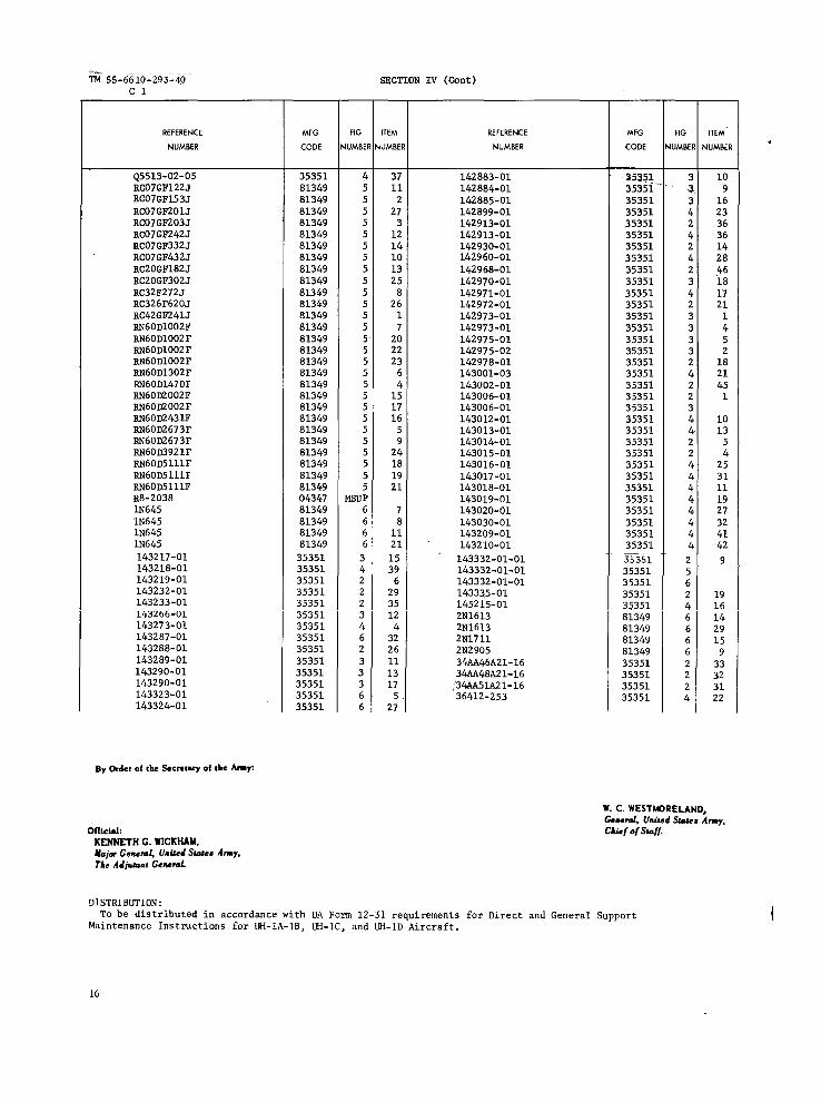
By Order of the Secretary of the Army:
Official:
W. C. WESTMORELAND,General, UnitedStates Army,Chief of Staff.
KENNETH G. WICKHAM,Major General, UnitedStates Army,The Adjutant General.
DISTRIBUTION:To be distributed in accordance with DA Form 12-31 (qty rqr blocks no.
337, 344, 35, and 354, cumulative for all blocks) requirements for Directand General Support Maintenance Instructions for UH-1A, UH-1B, UH-1C, UH-1Dand 1H Aircraft.
1


11


TECHNICAL MANUAL
TM 55-6610-293-40
TM 55-6610-293-40
HEADQUARTERSDEPARTMENT OF THE ARMY
W A S H I N G T O N, D. C., 7 September 1967
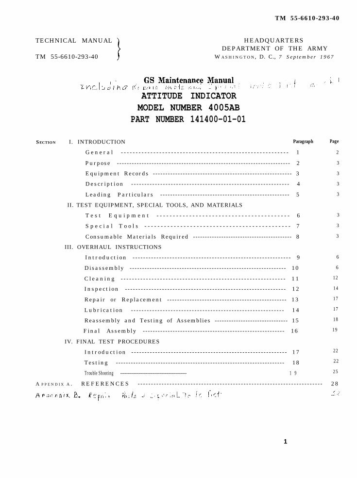
ATTITUDE INDICATORMODEL NUMBER 4005AB
PART NUMBER 141400-01-01
SECTION I. INTRODUCTION Paragraph
G e n e r a l - - - - - - - - - - - - - - - - - - - - - - - - - - - - - - - - - - - - - - - - - - - - - - - - - - - - - - - - - 1
Purpose ---------------------------------------------------------------------- 2
Equipment Records ---- - - - - - - - - - - - - - - - - - - - - - - - - - - - - - - - - - - - - - - - - - - - - - - - - - - - - 3
Descr ipt ion - - - - - - - - - - - - - - - - - - - - - - - - - - - - - - - - - - - - - - - - - - - - - - - - - - - - - - - - - - - - 4
Leading Particulars --- - - - - - - - - - - - - - - - - - - - - - - - - - - - - - - - - - - - - - - - - - - - - - - - - - 5
II. TEST EQUIPMENT, SPECIAL TOOLS, AND MATERIALS
T e s t E q u i p m e n t - - - - - - - - - - - - - - - - - - - - - - - - - - - - - - - - - - - - - - - - - 6
S p e c i a l T o o l s - - - - - - - - - - - - - - - - - - - - - - - - - - - - - - - - - - - - - - - - - - - - - 7
Consumable Materials Required ------------------------------------------ 8
III. OVERHAUL INSTRUCTIONS
Introduct ion - - - - - - - - - - - - - - - - - - - - - - - - - - - - - - - - - - - - - - - - - - - - - - - - - - - - - - - - - - - - 9
Disassembly ---- - - - - - - - - - - - - - - - - - - - - - - - - - - - - - - - - - - - - - - - - - - - - - - - - - - - - - - - - - - - 10
C l e a n i n g - - - - - - - - - - - - - - - - - - - - - - - - - - - - - - - - - - - - - - - - - - - - - - - - - - - - - - - - - - - 1 1
Inspect ion - - - - - - - - - - - - - - - - - - - - - - - - - - - - - - - - - - - - - - - - - - - - - - - - - - - - - - - - - - - - - 12
Repair or Replacement -- - - - - - - - - - - - - - - - - - - - - - - - - - - - - - - - - - - - - - - - - - - - - - - 13
Lubr i cat ion - - - - - - - - - - - - - - - - - - - - - - - - - - - - - - - - - - - - - - - - - - - - - - - - - - - - - - - - - - 14
Reassembly and Testing of Assemblies ------------------------------- 15
Final Assembly --- - - - - - - - - - - - - - - - - - - - - - - - - - - - - - - - - - - - - - - - - - - - - - - - - - - - - - - 16
IV. FINAL TEST PROCEDURES
Introduct ion - - - - - - - - - - - - - - - - - - - - - - - - - - - - - - - - - - - - - - - - - - - - - - - - - - - - - - - - - - - 17
Testing -------------------------------------------------------------------- 18
Trouble Shooting ------------------------------------------------------ 1 9
Page
2
3
3
3
3
3
3
3
6
6
12
14
17
17
18
19
22
22
25
A P P E N D I X A . REFERENCES - - - - - - - - - - - - - - - - - - - - - - - - - - - - - - - - - - - - - - - - - - - - - - - - - - - - - - - - - - - - - - - - - - - - - - 28
1

TM 55-6610-293-40
SECTION I
INTRODUCTION
1. General. b. Reporting of Improvements. Direct re-a. This technical manual comprises overhaul porting of errors, omissions, and recommenda-
instructions for Attitude Indicator, Model Num- tions for improving this manual by theber 4005AB, Part Number 141400-01-01 (see individual user is authorized and encouraged.figure 1), manufactured by Lear Siegler/Inc, DA Form 2028 will be used for reporting theseFederal Code Number 35351, Grand Rapids, improvements. DA Form 2028 will be completedMichigan. Sections I through IV of this by the individual using this manual and for-technical manual contain instructions for this warded directly to: Commanding General,model. Overhaul instructions for additional U. S. Army Aviation Materiel Command,models will be provided in Section V by the use ATTN: AMSAV-M, P. O. Box 209, St. Louis,of difference data sheets. Missouri, 63166.
Figure 1. Attitude Indicator, Part Number 141400-01-01
2
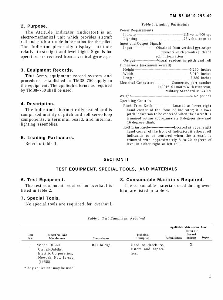
2. Purpose.The Attitude Indicator (Indicator) is an
electro-mechanical unit which provides aircraftroll and pitch attitude information for the pilot.The Indicator pictorially displays attituderelative to straight and level flight. Signals foroperation are received from a vertical gyroscope.
3. Equipment Records.The Army equipment record system and
procedures established in TM38–750 apply tothe equipment. The applicable forms as requiredby TM38–750 shall be used.
4. Description.The Indicator is hermetically sealed and is
comprised mainly of pitch and roll servo loopcomponents, a terminal board, and internallighting assemblies.
5. Leading Particulars.Refer to table 1.
T M 5 5 - 6 6 1 0 - 2 9 3 - 4 0
Table 1. Leading Particulars
Power RequirementsIndicator-------------------------------------------115 volts, 400 cpsLighting ---------------------------------------28 volts, ac or dc
Input and Output SignalsInput--------------------Obtained from vertical gyroscope
reference which provides pitch and roll information
Output------------------Visual readout in pitch and rollDimensions (maximum overall)
Height-----------------------------------------------5.260 inchesWidth ----------------------------------------------5.010 inchesLength------------------------------------------------7.386 inches
Electrical Connectors---------------Connector, part number142916–01 mates with connector,
Military Standard MS24009Weight---------------------------------------------------5-1/2 poundsOperating Controls
Pitch Trim Knob-----------------Located at lower righthand corner of the front of Indicator; it allowspitch indication to be centered when the aircraft istrimmed within approximately 8 degrees dive and16 degrees climb.
Roll Trim Knob---------------------Located at upper righthand corner of the front of Indicator; it allows rollindication to be centered when the aircraft istrimmed with approximately 8 to 20 degrees oflevel in either right or left roll.
SECTION II
TEST EQUIPMENT, SPECIAL TOOLS, AND MATERIALS
6. Test Equipment. 8. Consumable Materials Required.The test equipment required for overhaul is The consumable materials used during over-
listed in table 2.
7. Special Tools.No special tools are required
haul are listed in table 3.
for overhaul.
Table 2. Test Equipment Required
Applicable Maintenance LevelDirect Or
Item Model No. And Technical GeneralNo. Manufacturer Nomenclature Description Organization Support Depot
1 *Model BF-60 R/C bridge Used to check re- XCornell-Dubilier sisters and capaci-Electric Corporation, tors.Newark, New Jersey(14655)
* Any equivalent may be used.
3
TM 55-6610-293-40
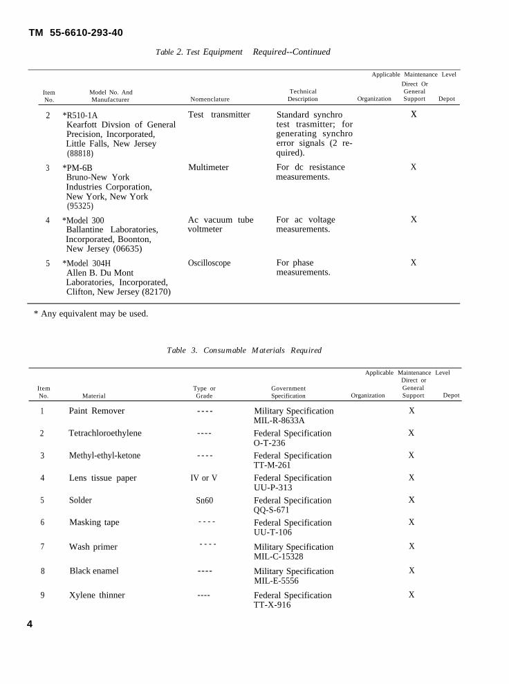
Table 2. Test Equipment Required--Continued
Applicable Maintenance Level
Direct OrItem Model No. And TechnicalNo.
GeneralManufacturer Nomenclature Description Organization Support Depot
2 *R510-1A Test transmitter Standard synchro xKearfott Divsion of General test trasmitter; forPrecision, Incorporated, generating synchroLittle Falls, New Jersey error signals (2 re-(88818) quired).
3 *PM-6B Multimeter For dc resistance XBruno-New York measurements.Industries Corporation,New York, New York(95325)
4 *Model 300 Ac vacuum tube For ac voltage XBallantine Laboratories, voltmeter measurements.Incorporated, Boonton,New Jersey (06635)
5 *Model 304H Oscilloscope For phase XAllen B. Du Mont measurements.Laboratories, Incorporated,Clifton, New Jersey (82170)
* Any equivalent may be used.
Table 3. Consumable Materials Required
Applicable Maintenance Level
ItemDirect or
Type or GovernmentNo.
GeneralMaterial Grade Specification Organization Support Depot
1
2
3
4
5
6
7
8
9
Paint Remover
Tetrachloroethylene
Methyl-ethyl-ketone
Lens tissue paper
Solder
Masking tape
Wash primer
Black enamel
Xylene thinner
- - - -
----
- - - -
IV or V
Sn60
- - - -
- - - -
----
----
Military Specification XMIL-R-8633A
Federal Specification XO-T-236Federal Specification XTT-M-261
Federal Specification XUU-P-313
Federal Specification XQQ-S-671
Federal Specification XUU-T-106
Military Specification XMIL-C-15328
Military Specification XMIL-E-5556
Federal Specification XTT-X-916
4

TM 55-6610-293-40
Table 3. Consumable Materials Required--Continued
Applicable Maintenance LevelDirect or
Item Type or Government GeneralNo. Material Grade Specification Organization Support Depot
10 Lubricating oil - - - - Military Specification XMIL-L-6085A
- - - - Military Specification XMIL-G-G23827
H Military Specification XMIL-S-22473
- - - - - - - - X
11
12
13
Grease
Adhesive
Hysol R8-2038 Base Resin,manufactured by HysolCorporation, Orlean, NewYork (04347), or equivalent
14 H2-3475 Hardener, manu-factured by HysolCorporation, Orlean, NewYork (04347), or equivalent
- - - -
- - - -
X
X
----
15 Cab-O-Sil Filler, manu-factured by Godfrey L.Cabot, Incorporated, Boston,Massachusetts (80798), orequivalent
M-5
16 XFreon PCA, manufacturedby E. I. du Pent, deNemours and Company,Incorporated, Chicago,Illinois (18873), orequivalent
----
X
X
17 Stur-D-Lace HL Soft FinishLacing Tape, manufacturedby Gudebrod Brothers SilkCompany, Incorporated, NewYork, New York (01670) orequivalent
--------
18 Wornow Ink Series “M”White Epoxy Coding Ink,manufactured by WornowProcess Paint Company,Los Angeles, California(79439) or equivalent
----
x
x
19 Tetrafluoroethylene Ad-hesive Tape, manufacturedby Chicago Gasket Company,Chicago, Illinois (06644),or equivalent
--------
20 Epon Adhesive VII PlusCuring Agent A, manufac-tured by Shell ChemicalCorporation, New York, NewYork (86961), orequivalent
---- ----
5

TM 55-6610-293-40
Table 3. Consumable Materials Required-Continued
Applicable Maintenance LevelDirect or
Item Type or GovernmentNo.
GeneralMaterial Grade Specification Organization Support Depot
21 EC847 Adhesive, manu- ---- - - - - Xfactured by MinnesotaMining and ManufacturingCompany, Detroit, Michigan(88525) or equivalent
SECTION III
OVERHAUL INSTRUCTIONS
9. Introduction. (2)
The following procedures outline step by stepoverhaul instructions for the Indicator. Theextent of overhaul will seldom require that eachstep be performed, thus only those steps re-quired to effect the necessary repair need beperformed.
10. Disassembly.(3)
a. Attitude Indicator, Part Number 141400-01-01. (4)
(1) If it is required that identificationplate (22, figure 2) be replaced, pro-ceed as follows: Record the infor-mation contained on plate, as it will berequired during reassembly. Insert aknife or sharp-edged tool under onecorner of plate and peel off.
1.2.3.4.5.
S tud
6 .7 .8 .9 .10.11.12.13.14.15.16.17.
Bezel Assembly
Yoke and Sphere AssemblyGear ClusterGear ClusterPlate Assembly
StudIndicator Subassembly (TB2)Washer
18.19.20.
ScrewScrew
S c r e wScrew
27.28.
ScrewWasherBrush Assembly (E1)StudWasher
21.22.23.24.25.26.
29. Clamp
42.43.44.45.46.47.48.49.50.
( B 2 B )
32.
30.31.
33.Screw 34.
Legend for figure 2
BearingTransformer (T1)Sealing StripCoverIdentification PlateConnector (J1)VentLatch and BracketPrinted Wiring
Terminal (E2)
RingShim, 0.025 inchesShim, 0.010 inchesShim, 0.005 inchesShim, 0.0015 inches
Remove paint as follows: mask offbezel assembly (1) and connector (23).Remove paint from Indicator usingpaint remover, Military SpecificationMIL-R-8633A. If complete paint re-moval is not required remove paintaround sealing strip (20) using paintremover.
Snip off end of evacuating vent (24).
Use a heavy duty soldering iron (250watts ) to remove excess solder aroundsealing strip (20 ). Grip sealing stripwith long nose pliers and carefullypull off. Discard sealing strip.
Note. At this time Indicator should beremoved to clean room conforming to Fed-eral Standard No. 209, class 100,000.
35.36.
37.38.39.40.
Assembly 41.
BracketMotor-Tachometer Generator
(MG2)ScrewClamp
ScrewWasherStudScrewClampHousing and Stator Assembly
BearingShim, 0.002 inchesShim, 0.010 inchesRing
6

Figure 2.
TM 55-6610-293-40
7

Figure 3.
T M 5 5 - 6 6 1 0 - 2 9 3 - 4 0
8

TM 55-6610-293-40
(5)
(6)(7)
(8)
(9)
(10)
(11)
(12)
1.2.3.4.5.6.7.8.9.
10.11.
KnobScale DialScrewKnobScale DialResistor, 4k ± 10%, 1w (R14)Bezel AssemblyResistor, 4k ± 10%, 1W (R17)Light ShieldLight WedgeRubber Pad
12.13.14.15.16.17.18.
19.20.
Figure 3. Bezel Assembly—Continued
Light Assembly (DS1)Rubber PadScrewMiniature AirplaneScale DialRubber PadPower-Off Warning Indicator(M1)ScrewClamp
Slide cover (21) off Indicator.
Caution: Printed wiring is attachedbetween internal assembly and con-nector in cover. Care must be observedso printed wiring is not damaged.
Do not remove printed wiring (26).Remove screws (11, 39, and 40) andwashers (10 and 41).Remove screws (27) and terminal(28). Remove transformer (19) andclamps (29 ).
Note. Cut lacing cord as necessary to gainaccess to or to remove components. Do notremove wiring unless necessary to replace acomponent.
Remove screws (17) and washers (16).Slide bracket (35) and brush assembly(14) away from ring assembly (23,figure 4) being careful not to bendbrushes.Carefully remove indicator subassem-bly (9, figure 2),Remove screws (37) and clamps (38).Remove motor-tachometer generator(36).Remove screws (7). Slide yoke andsphere assembly (3) and plate assem-bly (6) away from bezel assembly(1). Remove studs (2) from bezelassembly (1).
Caution: Do not break wires leadingto bezel assembly. Detail parts ofbezel assembly are loose. Use care notto damage parts.
(13)
(14)
(15)
Remove ring (30), shims (31, 32, 33,and 34), and bearing (18). Slide yokeand sphere assembly (3) away fromplate assembly (6). Note number ofshims (31, 32, 33, and 34) to aid, inreassembly.Remove bearing (46) from plate as-sembly (6). Remove screws (43),clamps (44), and housing and statorassembly (45) from plate assembly(6).Remove rings (49), shims (47 and 48),and gear clusters (4 and 5) from plateassembly (6).
b. Bezel Assembly.(1)(2)
(3)
(4)
(5)
(6)
(7)
Remove scale dial (16, figure 3).Remove screws (14), and miniatureairplane (15).Remove screws (19) and clamps (20).Slide power-off warning indicator(18) away from scale dial (16).Remove light assembly (12 ) and rub-ber pad (11 ) from bezel assembly.Remove light wedge (10) and lightshield (9) from bezel assembly.Do not remove knobs (1 and 4) unlessknobs or scale dials (2 and 5) are to bereplaced.Do not attempt to remove resistors (6and 8).
c. Yoke and Sphere Assembly.(1) Remove bank pointer (42, figure 4) by
breaking attaching epoxy seal andsliding bank pointer from mechanismmask (41 ).
9

Figure 4.
10
TM 55-6610-293-40
TM 55-6610-293-40
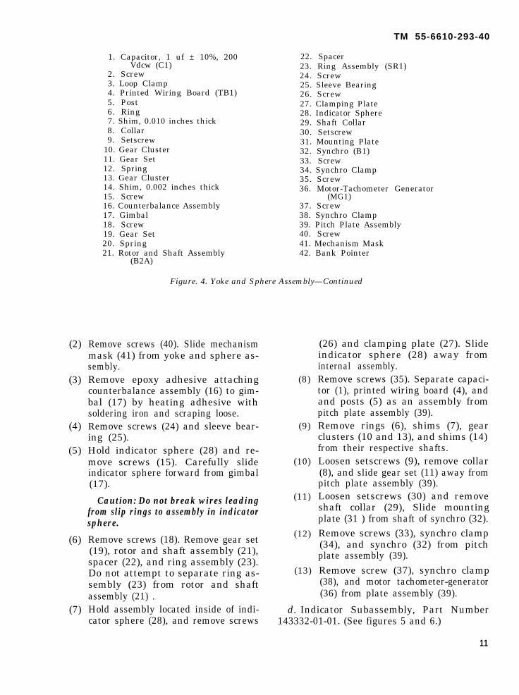
(2)
(3)
(4)
(5)
(6)
(7)
1. Capacitor, 1 uf ± 10%, 200Vdcw (C1)
2. Screw3. Loop Clamp4. Printed Wiring Board (TB1)5. Post6. Ring7. Shim, 0.010 inches thick8. Collar9. Setscrew
10. Gear Cluster11. Gear Set12. Spring13. Gear Cluster14. Shim, 0.002 inches thick15. Screw16. Counterbalance Assembly17. Gimbal18. Screw19. Gear Set20. Spring21. Rotor and Shaft Assembly
(B2A)
22. Spacer23. Ring Assembly (SR1)24. Screw25. Sleeve Bearing26. Screw27. Clamping Plate28. Indicator Sphere29. Shaft Collar30. Setscrew31. Mounting Plate32. Synchro (B1)33. Screw34. Synchro Clamp35. Screw36. Motor-Tachometer Generator
(MG1)37. Screw38. Synchro Clamp39. Pitch Plate Assembly40. Screw41. Mechanism Mask42. Bank Pointer
Figure. 4. Yoke and Sphere Assembly—Continued
Remove screws (40). Slide mechanismmask (41) from yoke and sphere as-sembly.Remove epoxy adhesive attachingcounterbalance assembly (16) to gim-bal (17) by heating adhesive withsoldering iron and scraping loose.Remove screws (24) and sleeve bear-ing (25).Hold indicator sphere (28) and re-move screws (15). Carefully slideindicator sphere forward from gimbal(17).
Caution: Do not break wires leadingfrom slip rings to assembly in indicatorsphere.
Remove screws (18). Remove gear set(19), rotor and shaft assembly (21),spacer (22), and ring assembly (23).Do not attempt to separate ring as-sembly (23) from rotor and shaftassembly (21) .Hold assembly located inside of indi-cator sphere (28), and remove screws
(8)
(9)
(10)
(11)
(12)
(13)
(26) and clamping plate (27). Slideindicator sphere (28) away frominternal assembly.Remove screws (35). Separate capaci-tor (1), printed wiring board (4), andand posts (5) as an assembly frompitch plate assembly (39).Remove rings (6), shims (7), gearclusters (10 and 13), and shims (14)from their respective shafts.Loosen setscrews (9), remove collar(8), and slide gear set (11) away frompitch plate assembly (39).Loosen setscrews (30) and removeshaft collar (29), Slide mountingplate (31 ) from shaft of synchro (32).Remove screws (33), synchro clamp(34), and synchro (32) from pitchplate assembly (39).Remove screw (37), synchro clamp(38), and motor tachometer-generator(36) from plate assembly (39).
d. Indicator Subassembly, Part Number143332-01-01. (See figures 5 and 6.)
11

TM 55-6610-293-40
1. Resistor, 240 ohms ± 5%, 2W(R6) -
2. Resistor, 15k ± 5%, 0.25w(R3)
3. Resistor, 20k ± 5%, 0.25 w(R28)
Resistor,, :.
4. Resistor, 147 ohms ± 1%,0.25 w (R29)
5. Resistor 267k ± 1%, 0.25w
Resistor,
6. Resistor, 13k ± 1%, 0.25w(R22)
7. Resistor 10k ± 1%, 0.25w
8. Resistor, 2.7k ± 5%, 1W (R16)Resistor
9. Resistor; 267k ± 1%, 0.25w(R8)
10.
11.
12.
13.
14.
15.
16.
17.
18.
Resistor,(R27)
Resistor,(R21)
(R18)
(R26)Resistor,
(R20)Resistor,
(R25)Resistor,
( R 5 )
(R10)Resistor,
(R11)
4.3k ± 5%, 0.25w
1.2k ± 5%, 0.25w
2.5k ± 5%, 0.25w
1.8k ± 5%, 0.5w
3.3k ± 5%, 0.25w
20k ± 1% 0.25w
2.43 ± 1%, 0.25w
20k ± 1%, 0.25w
5.11k ± 1%, 0.25w
19.
20.
21.
22.
23.
24.
25.26.
27.
Resistor, 5.11k ± 1%, 0.25w
Resistor, 10k ± 1%, 0.25w(R2)
Resistor, 5.11k ± 1%, 0.25w(R1)
Resistor, 10k ± 1%, 0.25w
Resistor, 10k ± 1%, 0.25w
Resistor, 3.9k ± 1%, 0.25w(R4)
Resistor, 3k ± 5%, 0.5w (R23)Resistor 62 ohms ± 5%, 1W
Resistor, 200 ohms ± 5 %,0.25w (R13)
Figure 5. Restitor Arrangement for Indicator Subassembly, Part Number 143332-01-01
(1) No disassembly is required. If replace- (2)ment of a part is necessary, refer toparagraph 13d.
11. Cleaning.a. Attitude Indicator, Part Number 141400-
01-01.
Note. All cleaned parts should be protected in cleanplastic boxes and bags until reassembled and shouldbe handled in such a way that contamination fromhandling is minimized, (3)
(1)
12
Clean bearings (18 and 46, figure 2)gears (4 and 5), and their attachingparts by washing in tetrachloro-ethylene, Federal Specification O–T- (4)236.
Residue from cement-spot locking ofattaching parts should be removed bycareful scraping and then by washingin or wiping with methyl-ethyl-ketone,Federal Specification TT-M-261 de-pending on whether the part is free orstill is attached near electrical parts.Repeat the method using tetrachloro-ethylene and dry with a vacuum source.
Clean transformer (19), motor-tachometer generator (36), printedwiring (26) and cover (21 ) using asoft brush and a vacuum source.
Clean plate assembly (6), housing andstator assembfly (45), and bracket

TM 55-6610-293-40
1.
2.
3.
4.
5.6.
7.
8.
9.
10.
11.
Capacitor, 47 uf ± 20%, 15Vdcw (C15)
Transistor Semiconductor De-vice (Q5)
Capacitor, 47 uf ± 20% 6Vdcw (C5)
Transistor SemiconductorDevice (Q6)
Heat SinkCapacitor, 47 uf ± 20%, 50
Vdcw (C9)Diode, Semiconductor Device
(CR6)Diode Semiconductor Device
(CR7)Transistor Semiconductor
Device (A4)Capacitor, 15 uf ± 2%, 20
Vdcw (C2)Diode Semiconductor Device
(CR1)
12.
13.
14.
15.
16.
17.
18.
19.
20.
21.
Diode Semiconductor Device(CR8)
Capacitor, 15 uf ± 20%, 20Vdcw (C6)
Transistor SemiconductorDevice (Q7)
Transistor SemiconductorDevice (Q1)
Capacitor, 0.047 uf ± 1070, 50Vdcw (C8)
Capacitor, 0.022 uf ± 10%, 50Vdcw (C4)
Capacitor, 22 uf ± 20%, 50Vdcw (C13)
Capacitor, 22 uf ± 20%, 50Vdcw (C14)
Capacitor, 25 uf –5 +30%,125 Vdcw (C11)
Diode Semiconductor Device(CR5)
22.
23.
24.
25.
26.
27.28.
29.
30.
31.
32.
Diode Semiconductor Devic(CR4)
Diode Semiconductor Device(CR3)
Capacitor, 47 uf ± 20%,Vdcw (C3)
Capacitor, 0.01 uf ± 20%, 2Vdcw (C7)
Transistor SemiconductorDevice (Q3)
Heat SinkDiode Semiconductor Devic
(CR2)Transistor Semiconductor
Device (Q2)Capacitor, 0.0022 uf ± 20%,
Capacitor, 1.5 uf ± 20%, 2Vdcw (C10)
Printed Wiring Board (C12
Figure 6. Capacitor and semiconductor~ Arrangement for Indicator Subassembly, PartNumber 14332-01-01-01
13

TM 55-6610-293-40
(35) using a clean, lint-free clothdampened with tetrachloroethylene.
(5) Clean brush assembly (14) by allow-ing a small amount of Freon PCA toflow over brushes. A suction sourceshould be used to suck Freon PCAthrough brushes.
b. Bezel Assembly.(1)
(2)
(3)
Residue from cement-spot locking ofattaching parts should be removed bycareful scraping and then by washingin or wiping with methyl-ethyl-ketone,depending on whether the part is freeor still is attached and near electricalparts. Repeat the method usingtetrachloroethylene and dry with avacuum source.
Clean glass in bezel assembly (7, figure3) and light wedge (10) with FreonPCA and lens tissue paper, FederalSpecification UU-P-313, type IV or V.
Clean face of scale dial (16) usingsticky side of pressure-sensitive papermasking tape, Federal SpecificationUU-T-106 to “dab-off” any dirt ordust. Avoid rubbing face of scale dial(16), as rubbing may produce shinyspots on paint.
c. Yoke and Sphere Assembly.(1)
(2)
Clean gear clusters (10 and 13, figure4) gear sets (11 and 19) and theirattaching parts by washing in tetra-chloroethylene.
Clean ring assembly (23 ) by usinglens tissue paper dampened in FreonPCA.
(3)
(4)
(5)
Clean indicator sphere (28) and faceof mechanism mask by using pressure-sensitive masking tape to “dabot-off”any dirt or dust. ‘Avoid rubbingindicator sphere and face of mech-nism mask to prevent shiny spots fromappearing on paint.Clean remaining metallic parts andshafts of synchro (32) and motor-tachometer generator (36) with alint-free cloth dampened with tetra-chloroethylene.Residue from cement-spot locking ofattaching parts should be removed bycareful scraping and then by washingin or wiping with methyl-ethyl-ketone,depending on whether the part is freeor still attached and near electricalparts. Repeat the method using tetra-chloroethylene and dry with a vacuumsource.
d. Indicator Subassembly, Part Number143332-01-01.
(1) Clean solder connections on printedwiring board (32, figure 6) with abristle brush moistened in tetrachloro-
(2)ethylene. Dry with a vacuum source.Remove any residue of cement-spotlocking by scraping and washing, firstwith methyl-ethyl-ketone, then withtetrachloroethylene. Dry with a vacu-um source.
12. Inspection.a. Attitude Indicator, Part Number 141400-
01-01.(1) Perform a visual and electrical inspec-
tion of Attitude Indicator as outlinedin tables 4 and 5.
Table 4. Visual Inspection Data For Attitude Indicator
Figure 2Index No. Nomenclature Inspect For
4 , 5 Gear cluster Chipped teeth, burrs, and excessive wear.23 Connector Bent or broken pins.26 Printed wiring Breaks, cracks, and poor connections.36 Motor-tachometer generator Defective teeth on shaft.
14

TM 55-6610-293-40
Table 5. Electrical Inspection Data For Attitude Indicator
Figure 2 ProcedureIndex No. Nomenclature Required Result
19 Transformer With multimeter, check dc re-sistance between windings:
1 and 3 15 ohms maximum2 and 3 4 ohms maximum4 and 5 4 ohms maximum6 and 8 3 ohms maximum7 and 8 1.3 ohms maximum8 and 9 1.3 ohms maximum
36 Motor-tachometergenerator
With multimeter, check dc re-sistance between leads:
blue and orange 43 to 63 ohmsred and black 64 to 96 ohmswhite and yellow 160 to 255 ohmsgreen and brown 254 to 384 ohms
45 Housing and stator Measure dc resistance between 370 ± 55.5 ohmsassembly leads with multimeter,
b. Bezel Assembly.(1) Perform a visual and electrical inspec-
tion of bezel assembly as outlined intables 6 and 7.
Table 6. Visual Inspection Data For Bezel Assembly
Figure 3Index No. Nomenclature Inspect For
7 Bezel assembly Scratches and nicks on glass.
10 Light wedge Scratches and nicks on glass.
Parts visible from front windows. Scratches or shiny spots on paint.
Table 7. Electrical Inspection Data For Bezel Assembly
Figure 3Index No. Nomenclature Procedure Required Result
6 and 8 Variable resistor With multimeter measure re- 4k ± 10%sistance between yellow andgreen leads.
12 Light assembly Check continuity of each lamp Continuity indication.with multimeter.
1 5

TM 55-6610-293-40
c. Yoke and Sphere Assembly.(1) Perform a visual and electrical inspec-
tion of yoke and sphere assembly asoutlined in tables 8 and 9.
Table 8. Visual Inspection Data For Yoke And Sphere Assembly
Figure 4Index No. Nomenclature Inspect For
28 Indicator sphere Cracks, defective paint, and shiny spots in paint.
10,11, Gears Chipped teeth, burrs, and excessive wear.13,19
- - Screws or nuts Defective threads.
Table 9. Electrical Inspection Data For Yoke And Sphere Assembly
Figure 4Index No. Nomenclature Procedure Required Result
21 Rotor and shaft Use multimeter to measureassembly resistance between leads:
blue and blackblue and yellowyellow and black
dc
109 ohms ± 1570109 ohms ± 15%109 ohms ± 15%(above values shall be within2 ohms of each other)
32 Synchro Use multimeter to check dc re- 60 ohms ± 2 %
sistance between all combina-tions of blue, yellow, and blackleads.
36 Motor-tachometer Use multimeter to measure dcgenerator resistance between leads:
red and black 64 to 96 ohmswhite and yellow 160 to 255 ohmsgreen and brown 254 to 384 ohms
d. Indicator Subassembly, Part Number143332-01-01.
(1) Perform a visual inspection of Indica-tor Subassembly as outlined in table10.
Table 10. Visual Inspection Data For Indicator Subassembly
Figure &Index No. Nomenclature Inspect For
All connections - - - - Breaks, cracks, and weak connections.
All connections - - - - Burned condition.
32, Figure 6 Printed wiring board Breaks in wiring.
16

0(2) Perform an electrical check of resistorsand capacitors suspected of beingdefective using R/C bridge.
13. Repair And Replacement.a. Attitude Indicator, Part Number 141400-
01-01.(1)
(2)
(3)
Solder a new vent (24, figure 2) intocover (21 ) each time the Indicator isunsealed. Unsolder old vent and dis-card. Solder new vent, making surethe solder joint is gas-tight. Usesolder, Federal Specification QQ-S–571, comp Sn60.To replace a part connected to printedwiring (26 ), use a 37.5-watt solderingiron and a vacuum source to removesolder connection on printed wiring.Slide a flat tool under printed wiringand pry printed wiring away fromcomponent.
Caution: Do not hold soldering ironon printed wiring connections anylonger than necessary to make solderflow.
If replacement of connector (23) orlatch and bracket assembly (25) isnecessary, replace connector, latch andbracket assembly, and cover (21 ) asan assembly.
b. Bezel Assembly.(1) If replacement of variable resistor (6
or 8, figure 3) is necessary, replaceresistors (6 and 8) and bezel assembly(7) as an assembly.
c. Yoke and Sphere Assembly.(1)
(2)
If replacement of ring assembly (23,figure 4) is necessary, heat epoxyadhesive as necessary to work ringassembly free. Replace with a newring assembly.To replace a defective bank pointer(42), remove bank pointer by slightlyheating attaching epoxy adhesive witha soldering iron. Remove all traces ofepoxy adhesive by scraping. Cleansurface with tetrachloroethylene, Fed-eral Specification O-T-236. Place new
TM 55-6610-293-40
bank pointer in position, apply epoxyresin, and allow to cure.
Note. Epoxy resin consists of 80 parts ofbase resin (Hysol R8-2038), 20 partshardener (HZ-3475), and 3 to 7 partsfiller (Cab-O-Sil, Grade M-5). Mix thorough-ly, apply to surfaces, and allow the cure24-48 hours at room temperature.
(3) To replace a defective capacitor (1unsolder and break loose capacityfrom printed wiring board (4). (Ifadhesive seal will not break loose, usea small amount of methyl-ethyl-ketoneto soften adhesive. ) Scrape adhesivefrom printed wiring board. Applyadhesive (EC847) between matingsurfaces of new capacitor and printedwiring board. Allow to dry for 1minutes. Solder leads of capacitor inplace. Use solder, Federal SpecificationQQ-S-571, composition Sn60.
d. Indicator Subassembly, Part Number143332-01-01.
(1) To replace any detail part, unsolderand break loose the part from printedwiring board (32, figure 6). Scrapeall old adhesive from printed wiringboard. Apply adhesive (Epon Adhesive VII plus Curing Agent A) to mating surfaces of detail part and printedwiring board. Allow to cure for 90minutes at 200°F (94°C). Solderleads as necessary. Use solder, FederalSpecification QQ-S-571, compositionSn60.
e. Replace all other parts found to be defective during inspection procedures.
14. Lubrication.a. Attitude Indicator, Part Number 141400
01-01.(1)
(2)
Lubricate bearings (18 and 46, figure2) with lubricating oil, Military Specification MIL-L-6085A.Apply a film of grease, Military Specification MIL-G-23827 to teeth andbores of gears (4 and 5) and to teethof shaft of motor-tachometer generator (36).
17
TM 55-6610-293-40
b. Bezel Assembly.(1) No lubrication is required.
c. Yoke and Sphere Assembly.(1)
(2)
Lubricate teeth and bores of gears (10,11, 13, figure 4) with grease, MilitarySpecification MIL-G-23837.Lubricate shaft of motor-tachometergenerator (36) and teeth of gear set(19) with grease, Military Specifica-tion MIL-G-23827.
d. Indicator Subassembly, Part Number143332-01-01,
(1) No lubrication is required.
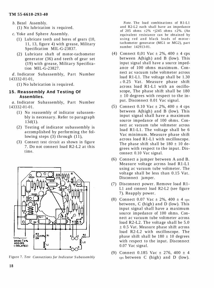
15. Reassembly And Testing OfAssemblies.
a. Indicator Subassembly, Part Number143332-01-01.
(1)
(2)
(3)
No reassembly of indicator subassem-bly is necessary. Refer to paragraph13d(1).Testing of indicator subassembly isaccomplished by performing the fol-lowing steps (3) through (11),Connect test circuit as shown in figure7. Do not connect load R2-L2 at thistime.
Figure 7. Test
18
Connections for Indicator Subassembly
(4)
(5)
(6)
(7)
(8)
(9)
Note. The load combinations of R1-L1and R2-L2 each shall have an impedanceof 205 ohms ±2% +j245 ohms ±2%. (Anequivalent resistance can be obtained byusing red and black leads of motor-tachometer generator (MG1 or MG2), partnumber 142913-01.
Connect 0,01 Vac ± 2%, 400 ± 4 cpsbetween A(high) and B (low). Thisinput signal shall have a source imped-ance of 100 ohms maximum. Con-nect ac vacuum tube voltmeter acrossload R1-L1. The voltage shall be 1.30± 0.25 Vat. Measure phase shiftacross load R1-L1 with an oscillo-scope, The phase shift shall be 180± 10 degrees with respect to the in-put. Disconnect 0.01 Vac signal.Connect 0.10 Vac ± 2%, 400 ± 4 cpsbetween A(high) and B (low). Thisinput signal shall have a maximumsource impedance of 100 ohms. Con-nect ac vacuum tube voltmeter acrossload R1-L1. The voltage shall be 6Vac minimum. Measure phase shiftacross load R1-L1 with oscilloscope.The phase shift shall be 180 ± 10 de-grees with respect to the input. Dis-connect 0.10 Vac signal.Connect a jumper between A and B.Measure voltage across load R1-L1using ac vacuum tube voltmeter. Thevoltage shall be less than 0.15 Vat.Disconnect jumper.Disconnect power. Remove load R1-L1 and connect load R2-L2 (see figure7). Reapply power.Connect 0.07 Vac ± 2%, 400 ± 4 cpsbetween, C (high) and D (low). Thisinput signal shall have a maximumsource impedance of 100 ohms. Con-nect ac vacuum tube voltmeter acrossload R2-L2. The voltage shall be 5.0± 0.5 Vat. Measure phase shift acrossload R2-L2 with oscilloscope. Thephase shift shall be 180 ± 10 degreeswith respect to the input. Disconnect0.07 Vac signal.
Connect 0.185 Vac ± 276, 400 ± 4cps between C (high) and D (low).

(10)
(11)
This input signal shall have a maxi-mum source impedance of 100 ohms.Connect ac vacuum tube voltmeteracross load R2-L2. The voltage shallbe a minimum of 12 Vat. Measurephase shift across load R2-L2 with anoscilloscope. The phase shift shall be180 ± 10 degrees with respect to theinput. Disconnect 0.185 Vac signal.Connect jumper between C and D.Measure voltage across load R2-L2using ac vacuum tube voltmeter. Thevoltage shall be less than 0.15 Vat.Remove power and all test connections.
b. Yoke and Sphere Assembly.(1)
(2)
(3)
(4)
(5)
(6)
(7)
Place motor-tachometer generator (36,figure 4) onto pitch plate assembly(39) and attach with synchro clamps(38) and screws (37).Place synchro (32) onto pitch plateassembly (39 ) and attach with syn-chro clamps (34) and screws (33).Slide mounting plate (31 ) onto syn-chro (32) shaft and attach with collar(29) and setscrews (30).
Note. Tighten setscrews (30) only enoughto keep mounting plate (31) from sliding,
Slide gear set (11 and 12) into placeon pitch plate assembly and attachwith setscrews and collar (8 and 9).Slide shims (14), gears (10 and 13),and shims (7) onto pitch plate assem-bly (39) and attach with rings (6).Check end play of gears (10 and 13).The end play shall be 0.008 to 0.003inches. Adjust rings (6) to obtainproper end play.
Note. It may be necessary to adjust posi-tion of gearset (11 and 12) to allow properalignment to gear (10).
Connect capacitor (1), printed wiringboard (4), and post (5) to pitch plateassembly (39) using screws (35).
Slide pitch plate assembly (39) intoindicator sphere (28) and attach intoplace with screws (26) and clampingplate (27).
(8)
(9)
(10)
(11)
(12)
(13)
TM 55-6610-293-40
Slide rotor and shaft assembly (21 )into gear set (19 and 20) and attachto gimbal (17) using screws (18).
Cement-lock screws (2, 15, 18, 33, 35,and 37) using adhesive, MilitarySpecification MIL-S-22473, Grade H.
Slide indicator sphere (28) into gimbal(17), place counterbalance assemblyin position and start screws (15) (donot tighten screws ). Loosen setscrews(30), tighten screws (15), and thenretighten setscrews (30).
Slide mechanism mask (41 ) into placeand attach with screws (40 ).
Cement-lock screws (15) and (40)using adhesive, Military SpecificationMIL-S-22473, Grade H.
No. testing of yoke and sphere assem-bly is required.
c. Bezel Assembly.
(1)
(2)
(3)
(4)
(5)
(6)
(7)
(8)
Reassemble scale dials (2 and 5, figure3) and attach with screws (3).
Position knobs (1 and 4) and tightensetscrews in knobs.
Slide light shield (9) and light wedge(10) into bezel assembly (7).
Position rubber pad (11 ) and lightassembly (12).
Slide power-off warning indicator (18)into scale dial (16) and attach withscrews (19 ).
Attach miniature airplane (15) toscale dial (16 ) with screws (14).
Place scale dial (5) into bezel assem-bly.
No testing ofquired.
16. Final Assembly.a. Attitude Indicator,
01-01.
bezel assembly is re-
Part Number 141400-
Note. Refer to wire list, table 11 as necessary duringreassembly.
19

TM 55-661O-293-40
Table 11. Wire List for Attitude Indicator, Part Number141400-01-01
Wire TerminationNo. Color From To
100105110111112115120
**********************************************
20
BrownRedBlackBlackBareOrangeYellowWhiteWhite/BlackGrayVioletGreenYellowOrangeBrownRedBlueBlackWhiteBlueGreenYellowBrownBlackOrangeRedWhiteBlueGreenYellowBrownBlackOrangeRedRedBrownRedBrownGreenYellowRedGreenYellowRedYellowBrownBareBareRed/WhiteBlack/WhiteBlackBlueYellow
T1-1T1-2T1-3T1-3T1-3T1-4T1-5SR1SR1SR1SR1SR1SR1SR1SR1SR1SR1SR1MG2MG2MG2MG2MG2MG2MG2MG2MG1MG1MG1MG1MG1MG1MG1MG1DS1-4DS1-3DS1-2DS1-1R17R17R17R14R14R14M1M1C1C1B1B1B1B1B1
TB2-11TB2-10TB2-13T1-8E2TB2-6TB2-7TB1-7TB1-2TB1-5TB1-8TB1-12TB1-4TB1-1TB1-6TB1-11TB1-9TB1-10TB2-10TB2-14TB2-8TB2-8TB2-5TB2-14TB2-1TB2-3TB1-1TB1-7TB1-7TB1-7TB1-8TB1-7TB1-13TB1-12TB2-15TB2–17TB2-15TB2-17T1-9T1-6TB2-9T1-9T1-7TB2-ATB2-12TB2-16TB1-1TB1-13TB1-6TB1-7TB1-2TB1-5TB1-4
Wire TerminationNo. Color From To
* Yellow B2 TB1-11* Black B2 TB1-10* Blue B2 TB1-9* Black B2 TB2-18* Red B2 TB2-19
● L e a d s a r e p a r t i t e m c o n n e c t e d .
(1)
(2)
(3)
(4)
(5)
(6)
(7)
(8)
Reassemble shims (47, figure 2) gears(4 and 5), and shims (48). Attachwith rings (49) and adjust rings untilthere is 0.003- to 0.008-inch end playon gears (4 and 5).Reassemble housing and stator as-sembly (45) onto plate assembly (6)and attach with clamps (44 ) andscrews (43). Slide bearing (46) intoplate assembly.Slide yoke and sphere assembly (3)into plate assembly (6). Using shims(31, 32, 33, and 34), shim yoke andsphere assembly (3) for end play of0.029 to 0.031 inch, Assemble ring(30).Reassemble studs (2) onto bezelassembly (1). Assemble screws (7)through plate assembly (6) and intostuds (2) .Position motor-tachometer generator(36) onto plate assembly (6). Attachwith clamps (38) and screws (37).Assemble indicator subassembly (9)to plate assembly (6) using screws(11, 39, and 40) and washers (10 and41).Carefully work brush assembly (14)and bracket (35) onto slip ring, At-tach bracket (35) to plate assembly(6) using washers (16) and screws(17). Use a small pointed instrumentto align brushes on slip ring. Theouter-most brushes should contact theouter-most ring.Assemble transformer (19 ) and ter-minal (28) using screws (27), clamps(29), and studs (15).
b. Alignment and Testing.(1) Refer to Section IV and calibrate two
standard test transmitters as outlined

(2)
(3)
(4)
(5)
(6)
(7)
in paragraph 18a. Connect power andstandard transmitters to indicator asshown in figure 8.Set standard transmitter dials to 180degrees. If the Indicator does notindicate zero (pitch trim and rolltrim variable resistors should be setto electrical zero) in pitch and roll,align as follows:
Warning: The Indicator will be ener-gized during following steps (3) and(4). Avoid contact with electrical con-nections and do not short out connec-tions with alignment instruments.
Loosen setscrews (30, figure 4) andmanually rotate Indicator to obtain apitch reading of zero degrees. Re-tighten setscrews (30).Loosen screws (43, figure 2). Manu-ally rotate housing and stator assem-bly (45) as necessary to obtain a rollreading of zero degrees. Retightenscrews (43).Perform all tests outlined in SectionIV.Upon completion of tests of SectionIV, cement-lock screws (7, 11, 12, 17,27, 37, 39, 40, and 43) using adhesive,Military Specification MIL-S-22473,Grade H.Secure all wires using Stur-D-LaceHL Soft Finish lacing tape.
c. Canning and Painting(1)
(2)
(3)
Hold cover firmly against bezel andapply tetrafluoroethylene adhesivetape to seam between case and bezel.Press tape firmly against unit withfingers. Tape should be centered overseam.Place new sealing strip (20, figure 2)over tape and center over seam. Holdsealing strip in place with maskingtape, Federal Specification UU-T-106.Move Indicator to a sealing area andtack solder sealing strip about unitusing a heavy-duty soldering iron. Usesolder, Federal Specification QQ-S-571, composition Sn60.
(4)
(5)
(6)
(7)
(8)
(9)
(10)
(11)
(12)
(13)
(14)
TM 55-6610-293-40
Remove masking tape, apply 1/2 psiof filling gas, and flow solder betweensealing strip, case and bezel. Useenough solder to fill void caused byraised edge of sealing strip. Soldershould form a continuous fillet whensoldering is completed. Clean solderedarea with a cloth moistened withtetrachloroethylene, Federal Specifi-cation O–T–236.
Note. The filling gas shall be composed ofan uncontaminated mixture of 5 ± 1 percentcarbon dioxide and the remainder helium.The dew point of the mixed gas shall be nohigher than —75°F.
The carbon dioxide and helium fillinggases used shall be of 99.99 percentminimum purity. Oxygen c o n t e n tshall not be greater than 0.002 percentfor helium. This gas shall be used forthe remainder of tests requiring gas.Apply 15 psi pressure of filling gasthrough vent, immerse in tetrachloro-ethylene, and examine for leaks. Ifunit leaks, rework seal.Bake Indicator in oven for one hourat 170° to 180°F with no vacuumapplied.Vacuum-bake Indicator at minimumof 27 inches of mercury for 2 hours.Remove Indicator from oven, attachto a dry gas source at a pressure of1 to 2 psi, and allow to cool.Cycle unit 3 to 5 times at 5 inchesof mercury vacuum and 5 psi pres-sure of filling gas.Cut vent (24) and allow pressure torelease. Solder seal vent (24).Clean Indicator with tetrachloroethyl-ene.Mask window of bezel assembly (1),connector (23 ), knobs ( 1 and 4, figure3) and dials (2 and 5).Apply one coat of wash primer, Mili-tary Specification MIL-C-15328 toIndicator. Allow 30 minutes to dry.Apply two coats of black enamel,Military Specification MIL-E–5556 toIndicator, allowing 20 minutes of dry-
21

TM 55-6610-293-40
(15)
(16)
(17)
(18)
ing time between coats. Use xylene,Federal Specification TT-X-916 tothin enamel if required.Allow to air dry for 2 hours. Removemasking tape from connector and win-dow.Conduct the test procedures of Sec-tion IV.Transfer information from old iden-tification plate (22, figure 2) onto newidentification plate. Peel off protec-tive backing on plate. Center platelengthwise on top of cover (21). Pressplate into place using firm pressure.Stencil following information on right
FINAL TEST PROCEDURE
17. Introduction.The following test procedures should be per-
formed before and after overhaul and at suchother times as necessary to check the operatingcharacteristics of the Indicator. The test re-sults may be used to provide a basis for local-izing faults that may occur in the unit andtherefore limit the extent of disassembly neces-sary for repairs.
18. Testing.a. Calibration of standard transmitters.
Note. Two transmitters are required.
(1)
(2)
(3)
Designate standard transmitter rotorleads as H and C. Ground C lead.Designate one standard transmitterstator lead as Z and connect it to leadc.Apply 26 Vac 400 cps across leadsH and C. Monitor ac voltage acrosstwo undesignated stator leads with acvoltmeter. Monitor ac voltage acrossone of undesignated stator leads andH. Turn rotor until ac voltage acrossH and one undesignated stator lead isapproximately maximum (about 35volts), at the same time ac voltageacross the two undesignated stator
(19)
(20)
side (as viewed from front) of cover(21), 1-1/2 inches from top and ap-proximately 1-1/2 inches from rearof Indicator. The letters should be3/32 inch high. Use white epoxycoding ink, Wornow Ink Series “M”.
“28 VOLT LIGHTING SYSTEMVOLTAGE NOT TO EXCEED 29.0
VOLTS”Stencil characters “J1” 1/2 inch aboveand centered over connector (23)using ink of step (18). The lettersshould be 1/4 inch high.
Test Indicator in accordance withSection IV.
SECTION IV
(4)
(5)
leads shall be minimum. Lock dial torotor with dial on zero.Monitor ac voltage across two undes-ignated stator leads (each in turn)and stator lead Z. Turn transmitterdial in direction of increasing num-bers. Designate as X stator lead inwhich voltage increases before de-creasing. Designate as Y the statorlead in which voltage decreases beforeincreasing.Disconnect power, external test equip-ment, and lead C from lead Z.
b. Pitch and Roll Sensing,(1)
(2)
(3)
Connect Indicator to standard trans-mitters and power sources as shownin figure 8 and apply power. The OFFindication shall disappear.
Set both standard transmitter dials toa reading of 180 degrees. The Indi-cator shall drive to within 1/2 degreeof zero in pitch and roll (pitch and rolltrim knobs shall be set at zero).
Increase and then decrease dial set-ting on roll standard transmitter. TheIndicator shall indicate a right rolland then a left roll.
22

(4)
(5)
Figure 8. Test Connections
Increase and then decrease dial set-ting on pitch standard transmitter.The Indicator shall indicate a climband then a dive.
Note. If roll indications or pitch indica-tions are reversed, recheck connections andstandard transmitter calibration. All visualobservation shall be made at a distance oftwo feet unless otherwise specified.
Reset both standard transmitters to180 degrees.
c. Pitch Trim(1)
(2)
(3)
Turn pitch trim knob to full clockwiseposition. Indicator shall indicate aminimum of 8 degrees dive.Turn pitch trim knob to full counter-clockwise position. Indicator shallindicate a minimum of 16 degreesclimb.Turn pitch trim knob to zero position.Indicator shall indicate within 1/2horizontal line width of zero. Loosenand reset pitch trim knob as necessary.
d. Roll Trim(1) Turn roll trim knob to full clockwise
(2)
(3)
TM 55-6610-293-40
position. Indicator shall indicate 8degrees to 20 degrees right roll.Turn roll trim knob to full counter-clockwise position. Indicator shall in-dicate 8 degrees to 20 degrees roll.Turn roll trim knob to zero.
e. Zeroing Adjustments.(1)
(2)
(3)
(4)
(5)
(6)
(7)
(8)
(9)
(10)
(11)
(12)
Place pitch standard transmitter to183 degrees, Adjust Indicator to zeropitch position using pitch trim knob.Loosen pitch trim knob from shaftand position knob to zero. Retightenpitch trim knob.Rotate pitch trim knob fully clock-wise. The Indicator shall indicate aminimum of 8 degrees dive.Rotate pitch trim knob fully counter-clockwise. The Indicator shall indicatea minimum of 16 degrees climb.Place pitch standard transmitter to177 degrees. Adjust Indicator to zeropitch position using pitch trim knob.Repeat steps (2), (3), and (4).Place pitch standard transmitter to180 degrees. Adjust pitch trim knobfor zero pitch reading on Indicator.Loosen pitch trim knob and place knobon zero. Retighten pitch trim knob.Place roll standard transmitter to 183degrees. Adjust Indicator to zero rollposition using roll trim knob.Loosen roll trim knob from shaft andposition knob to zero. Retighten rolltrim knob.Rotate roll trim knob fully clockwise.The Indicator shall indicate between8 degrees and 20 degrees right roll.Place roll standard transmitter to 177degrees. Adjust Indicator to zero rollposition using roll trim knob.Loosen roll trim knob from shaft andposition knob to zero. Retighten rolltrim knob.Rotate roll trim knob fully counter-clockwise, The Indicator shall displaybetween 8 degrees and 20 degrees leftroll.
28

TM 55-6610-293-40
(13) Place roll standard transmitter to 180degrees. Adjust roll trim knob forzero roll reading cm Indicator. Loosenroll trim knob and place knob on zero.Retighten roll trim knob.
f. Sensitivity.(1)
(2)
(3)
(4)
Rotate pitch standard transmitter 1/4degree from zero in each direction.The Indicator shall follow with asmooth perceptible movement.Repeat step (1) with pitch trim knobset in each of its extreme positionsand moving the transmitter 1/2 de-gree instead of 1/4 degree.Rotate roll standard transmitter 1/4degree in each direction from zero.The Indicator shall follow with asmooth perceptible movement.Repeat steps (3) with roll trim knobset in each of its extreme positionsand moving transmitter 1/2 degreeinstead of 1/4 degree.
g. Follow-up Rate.(1)
(2)
Rotate roll transmitter at 300 degreesper second minimum. The Indicatorshall follow at 300 degrees per secondminimum.Rotate pitch transmitter at 90 degreesper second minimum. The Indicatorshall follow at a minimum of 90degrees per second.
h. Follow-up Accuracy.(1) Place roll transmitter in each position
listed in table 12. The Indicator read-ings shall be as specified.
Table 12. Roll Follow-Up Accuracy
Indicator RollRoll Transmitter PresentationSetting (degrees) (degrees)
270 90 ± 2 right roll240 60 ± 2 right roll210 30 ± 1 right roll150 30 ± 1 left roll120 60 ± 2 left roll
90 90 ± 2 left roll
(2) Place pitch transmitter in each posi-tion listed in table 13. The Indicatorreadings shall be as specified.
Table 13. Pitch Follow-Up Accuracy
Indicator RollPitch Transmitter PresentationSetting (degrees) (degrees)
270 90 ± 2 climb240 60 ± 2 climb210 30 ± 1 climb150 30 ± 1 dive120 60 ± 2 dive
90 90 ± 2 dive
i. Gimbal Freedom.(1)
(2)
Rotate roll transmitter 360 degrees.Indicator shall follow smoothly with-out noticeable sticking, overshooting,jumping, or hunting. Return rolltransmitter to 180 degrees.Repeat step (1) using pitch transmit-ter. Results shall be same.
j. Hunting and Jumping.(1)
(2)
(3)
(4)
(5)
(6)
(1)
(2)
Set amplitude of signals of both pitchtransmitter and roll transmitter tozero. There shall be no noticeablehunting or jumping of Indicator withtransmitter amplitudes set at zero.Return amplitude of signals of trans-mitters to 26 Vat, 400 cps.Rotate pitch transmitter at a rate be-tween O degrees and 20 degrees persecond. Hunting and jumping shallnot exceed a peak-to-peak amplitudeof 1/8 degree.Repeat step (3) for pitch transmitterrate between 20 degrees and 90 de-grees per second. Peak-to-peak ampli-tude shall not exceed 1/2 degree.Repeat step (3) for pitch rate be-tween 90 degrees and 300 degrees persecond. Peak-to-peak amplitude shallnot exceed 1 degree. Return pitchtransmitter to 180 degrees.Repeat steps (3, 4, and 5) using rolltransmitter. The results shall be thesame.
k. Power Warning Indicator.Remove power from Indicator. Theword OFF shall immediately appear.Reapply power to Indicator. The wordOFF shall immediately disappear.
2 4

1. Interaction,(1) Connect two indicators to same pitch
transmitter.(2) Move pitch trim knob on one Indicator
through its range. There shall be nomore than 1/2 degree change in indi-cation on other Indicator. Removesecond Indicator.
m. Fogging.(1) Place Indicator in a controlled tem-
perature of 159.8°F (71°C) for onehour.
Note. Power to Indicator shall be left onduring this test.
TM 55-6610-293-40
(2) While still at this temperature, ruban ice cube on Indicator glass face fora period of 1 minute ± 5 seconds.
(3) Wipe glass dry. There shall be noevidence of water or oil fog.
n. Lighting.(1) Apply 28 volts ac or dc between Indi-
cater connector pins K and L.(2) Compare lighting to a standard
Lighting shall be comparable.
19. Troubleshooting.Use table 14 in conjunction with schematic
diagram figure 9, to help localize and correcttrouble conditions found during testing.
Table 14. Trouble Shooting Data
Trouble Probable Cause Remedy
POWER FAILURE FLAG DOES NOT Defective power-off warning in- Replace indicator.DISAPPEAR UPON APPLICATION OF dicator M1.POWER Defective resistors R23 and R24. Replace resistors.
Defective capacitor C11, C13, Replace capacitors.and C14.Defective diodes CR2 thru CR5. Replace diodes.Defective transformer T1. Replace transformer.
POWER FAILURE FLAG DOES NOT Defective power-off warning in- Replace indicator.REAPPEAR ON REMOVAL OF POWER dicator M1.
INDICATOR DOES NOT FOLLOW IN Defective synchro B1. Replace synchro.PITCH OR WILL NOT ZERO INPITCH
Defective transistors Q1 thru Replace as applicable.Q3 and associated resistors andcapacitors.Defective motor-tachometer gen- Replace motor-tachometererator MG1. generator.
INDICATOR DOES NOT FOLLOW IN Defective synchro B2. Replace synchro.ROLL OR WILL NOT ZERO IN ROLL Defective transistors Q4 thru Replace as applicable.
Q7 and associated resistors andcapacitors.Defective motor-tachometer gen- Replace motor-tachometererator MG2. generator.
PITCH TRIM KNOB DOES NOT DIS- Defective variable resistor R17. Replace resistor.PLACE INDICATOR TO MINIMUM Refective resistors R4 and R5. Replace resistors.REQUIRED POSITIONS Defective capacitors C4 and C2. Replace capacitors.
ROLL TRIM KNOB DOES NOT DIS- Defective variable resistor R14. Redate resistor.PLACE INDICATOR TO MINIMUM Defective resistor R10. Replace resistor.REQUIRED POSITIONS Defective capacitor C6. Replace capacitor.
INDICATOR HUNTS AND JUMPS Defective gear train or bearings. Replace or lubricate as re-quired.
Detective motor-tachometer Replace motor-tachometergenerator MG1 and MG2. generator.
25

Figure 9.
TM 95-6610-293-40
26

ReferenceDesignation
B1B2AB2BC1DS1E lE2J1MlMG1MG2R14R17SR1T1TB1TB2
Figure No.
44243222342334242
TM 55-6610-293-40
Index No.
322145
112142823183636
68
231949
Figure 9—Continued
2 7

T M 5 5 - 6 6 1 0 - 2 9 3 - 4 0
APPENDIX A
REFERENCES
Manual Number Manual TitleTM 38-750 Army Equipment Records Procedures
By Order of the Secretary of the Army:
HAROLD K. JOHNSON,General, United States Army,
Official: Chief of Staff.KENNETH G. WICKHAM,Major General, United States Army,The Adjutant General.
DISTRIBUTION:
To redistributed in accordance with DA Form 12-31 requirements for Direct and General Sup-port maintenance instructions for UH-1A-1B, UH-1C, UH-1D aircraft.
* U. S. GOVERNMENT PRINTING OFFICE: 1967-304430/49
28


TM 55-6610-293-40,

This fine document...
Was brought to you by me:
Liberated Manuals -- free army and government manuals
Why do I do it? I am tired of sleazy CD-ROM sellers, who take publicly available information, slap “watermarks” and other junk on it, and sell it. Those masters of search engine manipulation make sure that their sites that sell free information, come up first in search engines. They did not create it... They did not even scan it... Why should they get your money? Why are not letting you give those free manuals to your friends?
I am setting this document FREE. This document was made by the US Government and is NOT protected by Copyright. Feel free to share, republish, sell and so on.
I am not asking you for donations, fees or handouts. If you can, please provide a link to liberatedmanuals.com, so that free manuals come up first in search engines:
<A HREF=http://www.liberatedmanuals.com/>Free Military and Government Manuals</A>
– SincerelyIgor Chudovhttp://igor.chudov.com/
– Chicago Machinery Movers